WO2017163769A1 - 車両用視認装置 - Google Patents
車両用視認装置 Download PDFInfo
- Publication number
- WO2017163769A1 WO2017163769A1 PCT/JP2017/007475 JP2017007475W WO2017163769A1 WO 2017163769 A1 WO2017163769 A1 WO 2017163769A1 JP 2017007475 W JP2017007475 W JP 2017007475W WO 2017163769 A1 WO2017163769 A1 WO 2017163769A1
- Authority
- WO
- WIPO (PCT)
- Prior art keywords
- stand
- base
- mirror
- visual recognition
- mirror base
- Prior art date
- Legal status (The legal status is an assumption and is not a legal conclusion. Google has not performed a legal analysis and makes no representation as to the accuracy of the status listed.)
- Ceased
Links
Images



Classifications
-
- B—PERFORMING OPERATIONS; TRANSPORTING
- B60—VEHICLES IN GENERAL
- B60R—VEHICLES, VEHICLE FITTINGS, OR VEHICLE PARTS, NOT OTHERWISE PROVIDED FOR
- B60R1/00—Optical viewing arrangements; Real-time viewing arrangements for drivers or passengers using optical image capturing systems, e.g. cameras or video systems specially adapted for use in or on vehicles
- B60R1/02—Rear-view mirror arrangements
- B60R1/06—Rear-view mirror arrangements mounted on vehicle exterior
- B60R1/062—Rear-view mirror arrangements mounted on vehicle exterior with remote control for adjusting position
- B60R1/07—Rear-view mirror arrangements mounted on vehicle exterior with remote control for adjusting position by electrically powered actuators
- B60R1/074—Rear-view mirror arrangements mounted on vehicle exterior with remote control for adjusting position by electrically powered actuators for retracting the mirror arrangements to a non-use position alongside the vehicle
-
- B—PERFORMING OPERATIONS; TRANSPORTING
- B60—VEHICLES IN GENERAL
- B60R—VEHICLES, VEHICLE FITTINGS, OR VEHICLE PARTS, NOT OTHERWISE PROVIDED FOR
- B60R1/00—Optical viewing arrangements; Real-time viewing arrangements for drivers or passengers using optical image capturing systems, e.g. cameras or video systems specially adapted for use in or on vehicles
- B60R1/02—Rear-view mirror arrangements
- B60R1/06—Rear-view mirror arrangements mounted on vehicle exterior
-
- B—PERFORMING OPERATIONS; TRANSPORTING
- B60—VEHICLES IN GENERAL
- B60R—VEHICLES, VEHICLE FITTINGS, OR VEHICLE PARTS, NOT OTHERWISE PROVIDED FOR
- B60R1/00—Optical viewing arrangements; Real-time viewing arrangements for drivers or passengers using optical image capturing systems, e.g. cameras or video systems specially adapted for use in or on vehicles
- B60R1/02—Rear-view mirror arrangements
- B60R1/06—Rear-view mirror arrangements mounted on vehicle exterior
- B60R1/078—Rear-view mirror arrangements mounted on vehicle exterior easily removable; mounted for bodily outward movement, e.g. when towing
-
- B—PERFORMING OPERATIONS; TRANSPORTING
- B60—VEHICLES IN GENERAL
- B60R—VEHICLES, VEHICLE FITTINGS, OR VEHICLE PARTS, NOT OTHERWISE PROVIDED FOR
- B60R1/00—Optical viewing arrangements; Real-time viewing arrangements for drivers or passengers using optical image capturing systems, e.g. cameras or video systems specially adapted for use in or on vehicles
- B60R1/12—Mirror assemblies combined with other articles, e.g. clocks
- B60R2001/1253—Mirror assemblies combined with other articles, e.g. clocks with cameras, video cameras or video screens
Definitions
- the present invention relates to a vehicle visual recognition device.
- the vehicle outer mirror is a vehicular visual recognition device that enables the rear side of the vehicle to be visually recognized from the driver's seat.
- the vehicle outer mirror includes a mirror base attached to a side portion of the vehicle and a stand (shaft) fixed to the mirror base via a screw.
- the part (insertion hole or screw hole) through which a screw is penetrated or screwed is formed in a mirror base and a shaft. Therefore, it is difficult to reduce the size of the fixing portion between the mirror base and the stand.
- the present invention has been made in consideration of the above facts, and an object of the present invention is to obtain a vehicle visual recognition device that can reduce the size of a fixing portion between a base and a stand.
- a base that is fixed to the vehicle body side and has a base-side engagement portion and a support portion that supports the visual recognition portion that assists the occupant's visual recognition rotate about its axis.
- a rotating shaft portion to be moved; and a stand side engaging portion engaged with the base side engaging portion, wherein the base side engaging portion and the stand side engaging portion are engaged.
- the vehicle visual recognition device is the vehicle visual recognition device according to the first aspect, in which the base-side engagement portion and the stand-side engagement portion are a base-side screw portion and a stand-side screw portion, respectively. It is said that.
- the vehicular visual recognition device is the vehicular visual recognition device according to the second aspect, in which the side of the stand opposite to the rotation shaft portion is in a circumferential direction of the stand-side screw portion. It has an intersecting plane that intersects.
- the vehicle visual recognition device is fixed to the vehicle body side by fixing the base to the vehicle body side. Moreover, a support part can be displaced because the support part which supports a visual recognition part is rotated around the axis line of a rotating shaft part.
- the stand is fixed to the base by engaging the base side engaging portion provided on the base and the stand side engaging portion provided on the stand.
- the stand can be fixed to the base without using a fastening member for fixing the stand to the base. Thereby, it is not necessary to provide a space in which the fastening member is disposed in the fixing portion between the stand and the base, and the fixing portion between the stand and the base can be downsized.
- the stand-side screw portion of the stand and the base-side screw portion of the base can be screwed together by rotating the stand. Thereby, the stand can be easily fixed to the base.
- the vehicular visual recognition device of the third aspect of the present disclosure by engaging the tool with the crossing surface of the stand and rotating the tool, the stand-side screw portion of the stand and the base-side screw portion of the base are moved. Can be screwed together. Thereby, the stand can be easily fixed to the base.
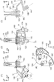
- FIG. 6 is a cross-sectional view showing a cross section of the mirror base and the stand cut along line 3C-3C, and (4) is a bottom view showing the mirror base and the stand.
- a vehicle door mirror device 10 as a vehicle visual device is visually recognized from the driver's seat on the vehicle rear side by being attached to a side door that constitutes a part of the vehicle body. It is possible to do.
- the front side in the vehicle front-rear direction is indicated by an arrow FR
- the outer side in the vehicle width direction is indicated by an arrow OUT
- the upper side in the vehicle vertical direction is indicated by an arrow UP.
- the front-rear direction of the vehicle and the up-down direction of the vehicle are indicated.
- a vehicle door mirror device 10 includes a mirror base 12 fixed to a side door and a stand 18 that rotatably supports a mirror support portion 14 as a support portion that supports a mirror 13 as a visual recognition portion via a storage device 16. And.
- the mirror base 12 is formed using a metal material such as an aluminum alloy.
- This mirror base 12 has a plate-like base wall portion 12A arranged along the side door, and a bolt for fixing the mirror base 12 to the side door while projecting obliquely downward from the base wall portion 12A to the vehicle.
- the mirror base 12 has a mirror base main body 12D that protrudes obliquely upward from the base wall 12A, and extends from the upper end of the mirror base main body 12D to the outside in the vehicle width direction.
- a stand fixing part 12E to which is fixed.
- the stand fixing portion 12E is formed in a cylindrical shape with the vertical direction as the axial direction, and a cylindrical portion 12F into which a part of the stand 18 is inserted. Is provided.
- a mirror base side screw portion 12G is formed with the vertical direction as an axial direction.
- the mirror base side screw portion 12G is a female screw portion.
- the lower end 12H of the inner peripheral portion of the cylindrical portion 12F is gradually enlarged in diameter toward the lower side. Thereby, the lower end portion 12H in the inner peripheral portion of the cylindrical portion 12F is gently curved.
- the mirror base 12 described above is covered with a mirror base cover 20.
- the stand 18 is formed using a metal material such as an aluminum alloy similarly to the mirror base 12, and the stand 18 is formed in a cylindrical shape having the vertical direction as an axial direction. Further, the stand 18 includes a rotating shaft portion 18A to which a storage device 16 (see FIG. 1) attached to the mirror support portion 14 is engaged. Note that the axial direction of the rotating shaft portion 18A (the axial direction of the stand 18) coincides with the vertical direction of the vehicle. A plurality of locking grooves 18B in which a part of the storage device 16 is locked are formed in the rotation shaft portion 18A along the axial direction.
- the lower end of the stand 18 is a tool engagement portion 18C formed in a substantially hexagonal shape having six intersecting surfaces intersecting the circumferential direction of the stand-side screw portion 18D.
- the shape of the outer peripheral surface of the tool engaging portion 18C is such that a socket that is a tool for rotating a hex nut or a bolt can be engaged.
- a stand-side screw portion 18D as a stand-side engagement portion is formed on the outer peripheral portion of a portion of the stand 18 between the rotation shaft portion 18A and the tool engagement portion 18C with the vertical direction as the axial direction.
- the stand side screw portion 18D is a male screw portion.
- a boundary portion 18E between the stand side screw portion 18D and the tool engaging portion 18C in the stand 18 is gradually enlarged in diameter toward the lower side. Thereby, the boundary part 18E of the stand side screw part 18D and the tool engaging part 18C in the stand 18 is gently curved.
- the stand 18 described above is covered with the outer mirror cover 22 together with the storage device 16 and the mirror support portion 14.
- the rotating shaft portion 18A of the stand 18 is inserted into the cylindrical portion 12F of the mirror base 12.
- the stand 18 is rotated through the socket engaged with the tool engaging portion 18 ⁇ / b> C of the stand 18.
- the stand side screw part 18D of the stand 18 and the mirror base side screw part 12G of the mirror base 12 are screwed together.
- a predetermined torque is applied to the stand 18 in a state where the tool engaging portion 18C of the stand 18 is in contact with the cylindrical portion 12F of the mirror base 12.
- the stand 18 is in a state where the lower end 12H of the inner peripheral portion of the cylindrical portion 12F of the mirror base 12 and the boundary 18E between the stand-side screw portion 18D and the tool engaging portion 18C of the stand 18 are in close contact with each other. Is fixed to the mirror base 12.
- the mirror base 12 is fixed to the side door by screwing a bolt (not shown) into the boss portion 12 ⁇ / b> C of the mirror base 12. . Thereby, the vehicle door mirror device 10 is fixed to the side door.
- the mirror support portion 14 that supports the mirror 13 is rotated around the axis of the rotation shaft portion 18 ⁇ / b> A of the stand 18 together with the storage device 16, thereby unfolding the mirror support portion 14. It can be displaced between the position and the storage position.
- the stand 18 is fixed to the mirror base 12 by engaging the mirror base side screw portion 12G of the mirror base 12 with the stand side screw portion 18D of the stand 18.
- the stand 18 can be fixed to the mirror base 12 without using a fastening member for fixing the stand 18 to the mirror base 12.
- the size of the stand side screw portion 18D of the stand 18) can be reduced.
- the stand side screw portion 18D of the stand 18 and the mirror base side screw portion 12G of the mirror base 12 can be screwed together.
- the stand 18 can be easily fixed to the mirror base 12.
- the stand 18 can be easily rotated through the socket by providing the stand 18 with a tool engaging portion 18C that can engage the socket.
- the lower end 12H of the inner peripheral portion of the cylindrical portion 12F of the mirror base 12 and the boundary 18E between the stand side screw portion 18D and the tool engaging portion 18C of the stand 18 are gently curved.
- the stand 18 and the mirror base 12 can be formed separately, so that the stand 18 can be formed without being affected by the direction in which the mold forming the mirror base 12 is pulled out.
- the thickness of the stand 18 can be made uniform.
- a free solidified surface is easily formed at the boundary between the stand 18 and the mirror base 12, but in this embodiment, the stand 18 and the mirror base are formed.
- the stand 18 is fixed to the mirror base 12 by screwing the stand side screw portion 18D of the stand 18 and the mirror base side screw portion 12G of the mirror base 12 .
- the invention is not limited to this.
- the stand 18 is fixed to the mirror base 12 by adopting a configuration in which the portion of the stand 18 where the stand-side screw portion 18D is formed and the portion of the mirror base 12 where the mirror base-side screw portion 12G is formed are press-fitted together. May be.
- the stand 18 and the mirror base 12 are formed using a resin material
- the stand 18 may be fixed to the mirror base 12 by joining them together by welding or the like.
- the present invention is not limited to this.
- the present invention can be applied to a fender mirror, a fender under mirror, or the like as a vehicle visual recognition device attached to a fender of a vehicle body.
- the present invention may be applied to a vehicular visual recognition device including a camera as a visual recognition unit instead of the mirror 13.
Landscapes
- Engineering & Computer Science (AREA)
- Multimedia (AREA)
- Mechanical Engineering (AREA)
- Rear-View Mirror Devices That Are Mounted On The Exterior Of The Vehicle (AREA)
Abstract
車両用ドアミラー装置(10)は、車体側に固定されると共にミラーベース側螺子部(12G)を有するミラーベース(12)を備えている。また、車両用ドアミラー装置(10)は、ミラー(13)を支持するミラー支持部(14)がその軸線回りに回動される回動軸部(18A)と、ミラーベース側螺子部(12G)と係合されるスタンド側螺子部(18D)と、を有するスタンド(18)を備えている。そして、ミラーベース側螺子部(12G)とスタンド側螺子部(18D)とが係合された状態で、スタンド(18)がミラーベース(12)に固定されている。
Description
本発明は、車両用視認装置に関する。
国際公開第2006/038274号には、運転席から車両の後方側を視認することを可能とする車両用視認装置である車両用アウターミラーが開示されている。この、車両用アウターミラーは、車両の側部に取付けられるミラーベースと、ミラーベースに螺子を介して固定されるスタンド(シャフト)と、を含んで構成されている。
ところで、ミラーベースとスタンドとを当該ミラーベース及びスタンドとは別部材の螺子を介して固定する構成では、螺子が挿通又は螺合される部分(挿通孔又は螺子孔)をミラーベース及びシャフトに形成する必要があり、ミラーベースとスタンドとの固定部の小型化を図ることが難しい。
本発明は上記事実を考慮し、ベースとスタンドとの固定部の小型化を図ることができる車両用視認装置を得ることが目的である。
本開示の第1の態様の車両用視認装置は、車体側に固定されると共にベース側係合部を有するベースと、乗員の視認を補助する視認部を支持する支持部がその軸線回りに回動される回動軸部と、前記ベース側係合部と係合されるスタンド側係合部と、を有し、前記ベース側係合部と前記スタンド側係合部とが係合された状態で前記ベースに固定されるスタンドと、を備えている。
本開示の第2の態様の車両用視認装置は、第1の態様の車両用視認装置において、前記ベース側係合部及び前記スタンド側係合部は、それぞれベース側螺子部及びスタンド側螺子部とされている。
本開示の第3の態様の車両用視認装置は、第2の態様の車両用視認装置において、前記スタンドにおける前記回動軸部とは反対側は、前記スタンド側螺子部の周方向に対して交差される交差面を有している。
本開示の第1の態様の車両用視認装置によれば、ベースが車体側に固定されることで、当該車両用視認装置が車体側に固定される。また、視認部を支持する支持部が回動軸部の軸線回りに回動されることで、支持部を変位させることができる。ここで、本開示の第1の態様では、ベースに設けられたベース側係合部とスタンドに設けられたスタンド側係合部とが係合されることで、スタンドがベースに固定される。このように、本開示の第1の態様では、スタンドをベースに固定するための締結部材を用いることなく、スタンドをベースに固定することができる。これにより、スタンドとベースとの固定部に上記締結部材が配置されるスペースを設けることが不要となり、スタンドとベースとの固定部の小型化を図ることができる。
本開示の第2の態様の車両用視認装置によれば、スタンドを回転させることにより、スタンドのスタンド側螺子部とベースのベース側螺子部とを螺合させることができる。これにより、スタンドをベースに容易に固定することができる。
本開示の第3の態様の車両用視認装置によれば、工具をスタンドの交差面に係合させて、工具を回転させることにより、スタンドのスタンド側螺子部とベースのベース側螺子部とを螺合させることができる。これにより、スタンドをベースに容易に固定することができる。
図1に示されるように、本発明の実施形態に係る車両用視認装置としての車両用ドアミラー装置10は、車体の一部を構成するサイドドアに取付けられることにより運転席から車両後方側を視認することを可能とするものである。なお、車両前後方向前方側を矢印FRで示し、車幅方向外側を矢印OUTで示し、車両上下方向上側を矢印UPで示す。また、以下の説明で、単に前後、上下の方向を示す場合は、車両前後方向の前後、車両上下方向の上下を示すものとする。
車両用ドアミラー装置10は、サイドドアに固定されるミラーベース12と、視認部としてのミラー13を支持する支持部としてのミラー支持部14を格納装置16を介して回動可能に支持するスタンド18と、を含んで構成されている。
図2及び図3の(1)~(4)に示されるように、ミラーベース12は、アルミニウム合金等の金属材料を用いて形成されている。このミラーベース12は、サイドドアに沿って配置される板状の基壁部12Aと、基壁部12Aから車両斜め下方側へ向けて突出すると共にミラーベース12をサイドドアに固定するためのボルトが螺合される螺合孔12Bを有する3つのボス部12Cと、を備えている。また、ミラーベース12は、基壁部12Aから車両斜め上方側へ向けて突出するミラーベース本体部12Dと、ミラーベース本体部12Dの上端部から車幅方向外側へ向けて延びると共に後述するスタンド18が固定されるスタンド固定部12Eと、を備えている。
図2及び図3の(3)に示されるように、スタンド固定部12Eには、上下方向を軸方向とする筒状に形成されていると共にスタンド18の一部が挿通される筒状部12Fが設けられている。この筒状部12Fの内周部の下方側には、ミラーベース側係合部としてのミラーベース側螺子部12Gが上下方向を軸方向として形成されている。なお、このミラーベース側螺子部12Gは雌螺子部である。また、筒状部12Fの内周部における下方側の端部12Hは、下方側に向かうにつれて次第に拡径されている。これにより、筒状部12Fの内周部における下方側の端部12Hが緩やかに湾曲されている。なお、以上説明したミラーベース12は、ミラーベースカバー20に覆われている。
スタンド18は、ミラーベース12と同様にアルミニウム合金等の金属材料を用いて形成されており、このスタンド18は、上下方向を軸方向とする筒状に形成されている。また、スタンド18は、ミラー支持部14に取付けられた格納装置16(図1参照)が係合される回動軸部18Aを備えている。なお、この回動軸部18Aの軸方向(スタンド18の軸方向)は、車両の上下方向と一致している。回動軸部18Aには、格納装置16の一部が係止される複数の係止溝18Bがその軸方向に沿って形成されている。また、スタンド18における下方側の端部は、スタンド側螺子部18Dの周方向と交差する6つの交差面を有する略6角形状に形成された工具係合部18Cとされている。この工具係合部18Cの外周面の形状は、六角ナットやボルトを回転させるための工具であるソケットが係合可能な形状とされている。さらに、スタンド18における回動軸部18Aと工具係合部18Cとの間の部位の外周部には、スタンド側係合部としてのスタンド側螺子部18Dが上下方向を軸方向として形成されている。なお、このスタンド側螺子部18Dは雄螺子部である。また、スタンド18におけるスタンド側螺子部18Dと工具係合部18Cとの境界部18Eは、下方側に向かうにつれて次第に拡径されている。これにより、スタンド18におけるスタンド側螺子部18Dと工具係合部18Cとの境界部18Eが緩やかに湾曲されている。以上説明したスタンド18は、格納装置16及びミラー支持部14と共にアウタミラーカバー22に覆われている。
次に、スタンド18をミラーベース12に固定する工程について説明する。
図4の(1)及び(2)に示されるように、先ずスタンド18の回動軸部18Aをミラーベース12の筒状部12Fに挿通させる。ついで、スタンド18を当該スタンド18の工具係合部18Cに係合されたソケットを介して回転させる。これにより、スタンド18のスタンド側螺子部18Dとミラーベース12のミラーベース側螺子部12Gとが螺合される。そして、図4の(3)に示されるように、スタンド18の工具係合部18Cがミラーベース12の筒状部12Fに当接された状態で、スタンド18に所定のトルクが加えられることにより、ミラーベース12の筒状部12Fの内周部における下方側の端部12Hとスタンド18におけるスタンド側螺子部18Dと工具係合部18Cとの境界部18Eとが密着された状態で、スタンド18がミラーベース12に固定される。
なお、スタンド18のスタンド側螺子部18Dとミラーベース12のミラーベース側螺子部12Gとの間に螺子の緩みを抑制する緩止材を介在させてもよい。
(本実施形態の作用並びに効果)
次に、本実施形態の作用並びに効果について説明する。
次に、本実施形態の作用並びに効果について説明する。
図1に示されるように、本実施形態の車両用ドアミラー装置10によれば、ミラーベース12のボス部12Cに図示しないボルトが螺入されることで、ミラーベース12がサイドドアに固定される。これにより、車両用ドアミラー装置10がサイドドアに固定される。
また、格納装置16が作動されて、ミラー13を支持するミラー支持部14が、格納装置16と共にスタンド18の回動軸部18Aの軸線回りに回動されることで、ミラー支持部14を展開位置と格納位置との間で変位させることができる。
ここで、本実施形態では、ミラーベース12のミラーベース側螺子部12Gとスタンド18のスタンド側螺子部18Dとが係合されることで、スタンド18がミラーベース12に固定される。このように、本実施形態では、スタンド18をミラーベース12に固定するための締結部材を用いることなく、スタンド18をミラーベース12に固定することができる。これにより、スタンド18とミラーベース12との固定部に上記締結部材が配置されるスペースを設けることが不要となり、スタンド18とミラーベース12との固定部(ミラーベース12のミラーベース側螺子部12G及びスタンド18のスタンド側螺子部18Dの周縁部)の小型化を図ることができる。
また、本実施形態では、スタンド18を回転させることにより、スタンド18のスタンド側螺子部18Dとミラーベース12のミラーベース側螺子部12Gとを螺合させることができる。これにより、スタンド18をミラーベース12に容易に固定することができるようになっている。これに加えて、本実施形態では、ソケットが係合可能な工具係合部18Cをスタンド18に設けることにより、スタンド18をソケットを介して容易に回転させることができるようになっている。
さらに、本実施形態では、ミラーベース12の筒状部12Fの内周部における下方側の端部12H及びスタンド18におけるスタンド側螺子部18Dと工具係合部18Cとの境界部18Eを緩やかに湾曲させた構成とすることにより、両者の接触部及びその周縁部に生じる応力を緩和することができる。
また、本実施形態では、スタンド18とミラーベース12とを別体構成とすることにより、ミラーベース12を形成する金型の抜き方向の影響を受けることなく、スタンド18を形成することができると共にスタンド18の肉厚の均一化を図ることができる。また、スタンド18とミラーベース12とが鋳造で一体に形成された構成では、スタンド18とミラーベース12との境界部に自由凝固面が形成され易いが、本実施形態では、スタンド18とミラーベース12とを別体構成とすることにより、スタンド18とミラーベース12との境界部に自由凝固面が形成されることを回避又は抑制することができる。
なお、本実施形態では、スタンド18のスタンド側螺子部18Dとミラーベース12のミラーベース側螺子部12Gとを螺合させることにより、スタンド18をミラーベース12に固定した例について説明したが、本発明はこれに限定されない。例えば、スタンド18のスタンド側螺子部18Dが形成された部位とミラーベース12のミラーベース側螺子部12Gが形成された部位とを互いに圧入させる構成とすることにより、スタンド18をミラーベース12に固定してもよい。また、スタンド18及びミラーベース12が樹脂材料を用いて形成されている場合においては、両者を溶着等により接合することにより、スタンド18をミラーベース12に固定してもよい。
また、本実施形態では、サイドドアに固定される車両用ドアミラー装置10に本発明を適用した例について説明したが、本発明はこれに限定されない。例えば、車体のフェンダに取付けられる車両用視認装置としてのフェンダミラーやフェンダアンダミラー等に本発明を適用することもできる。また、ミラー13に代えて視認部としてのカメラを含んで車両用視認装置に本発明を適用してもよい。
以上、本発明の一実施形態について説明したが、本発明は、上記に限定されるものでなく、その主旨を逸脱しない範囲内において上記以外にも種々変形して実施することが可能であることは勿論である。
2016年3月24日に出願された日本国特許出願2016-60444号の開示は、その全体が参照により本明細書に取り込まれる。
Claims (6)
- 車体側に固定されると共にベース側係合部を有するベースと、
乗員の視認を補助する視認部を支持する支持部がその軸線回りに回動される回動軸部と、前記ベース側係合部と係合されるスタンド側係合部と、を有し、前記ベース側係合部と前記スタンド側係合部とが係合された状態で前記ベースに固定されるスタンドと、
を備えた車両用視認装置。 - 前記ベース側係合部及び前記スタンド側係合部は、それぞれベース側螺子部及びスタンド側螺子部とされている請求項1記載の車両用視認装置。
- 前記スタンドにおける前記回動軸部とは反対側は、前記スタンド側螺子部の周方向に対して交差される交差面を有している請求項2記載の車両用視認装置。
- 前記スタンドにおける下方側の端部は、前記スタンド側螺子部の周方向と交差する6つの交差面を有する略6角形状に形成された工具係合部とされている請求項2記載の車両用視認装置。
- 前記スタンドにおける前記回動軸部と前記工具係合部との間の部位の外周部に、前記スタンド側螺子部が上下方向を軸方向として形成されている請求項4記載の車両用視認装置。
- 前記スタンド側螺子部は雄螺子部である請求項5記載の車両用視認装置。
Priority Applications (1)
| Application Number | Priority Date | Filing Date | Title |
|---|---|---|---|
| US16/085,819 US20190047474A1 (en) | 2016-03-24 | 2017-02-27 | Viewing device for vehicle |
Applications Claiming Priority (2)
| Application Number | Priority Date | Filing Date | Title |
|---|---|---|---|
| JP2016060444A JP2017171172A (ja) | 2016-03-24 | 2016-03-24 | 車両用視認装置 |
| JP2016-060444 | 2016-03-24 |
Publications (1)
| Publication Number | Publication Date |
|---|---|
| WO2017163769A1 true WO2017163769A1 (ja) | 2017-09-28 |
Family
ID=59901252
Family Applications (1)
| Application Number | Title | Priority Date | Filing Date |
|---|---|---|---|
| PCT/JP2017/007475 Ceased WO2017163769A1 (ja) | 2016-03-24 | 2017-02-27 | 車両用視認装置 |
Country Status (3)
| Country | Link |
|---|---|
| US (1) | US20190047474A1 (ja) |
| JP (1) | JP2017171172A (ja) |
| WO (1) | WO2017163769A1 (ja) |
Families Citing this family (1)
| Publication number | Priority date | Publication date | Assignee | Title |
|---|---|---|---|---|
| US10981509B2 (en) * | 2017-05-11 | 2021-04-20 | SMR Patents S.à r.l. | Drive mechanism and rear view device |
Citations (5)
| Publication number | Priority date | Publication date | Assignee | Title |
|---|---|---|---|---|
| JPS59146606U (ja) * | 1983-02-07 | 1984-10-01 | 稲垣 芳美 | ボルト |
| JPH0718013U (ja) * | 1992-09-09 | 1995-03-31 | 浩伸 鵜飼 | ボルト及びその締付け工具 |
| JPH08183392A (ja) * | 1994-12-29 | 1996-07-16 | Murakami Kaimeidou:Kk | 可倒規制手段を具えたドアミラー |
| JP3180705U (ja) * | 2011-10-05 | 2013-01-10 | 健生實業股▲分▼有限公司 | 可倒式バックミラー |
| JP2015030300A (ja) * | 2013-07-31 | 2015-02-16 | スズキ株式会社 | ドアミラー取付構造 |
Family Cites Families (2)
| Publication number | Priority date | Publication date | Assignee | Title |
|---|---|---|---|---|
| CA2348323C (en) * | 2001-05-24 | 2006-02-14 | Multimatic Inc. | Automotive door hinge with removable component adapted for structural reassembly |
| KR101775976B1 (ko) * | 2013-06-26 | 2017-09-07 | 메크라 랑 게엠베하 운트 코 카게 | 제 1 및 2 조인트 아암을 피봇식으로 연결하기 위한 조인트 장치, 거울 리테이너 및 이러한 조인트 장치를 포함하는 거울 |
-
2016
- 2016-03-24 JP JP2016060444A patent/JP2017171172A/ja active Pending
-
2017
- 2017-02-27 US US16/085,819 patent/US20190047474A1/en not_active Abandoned
- 2017-02-27 WO PCT/JP2017/007475 patent/WO2017163769A1/ja not_active Ceased
Patent Citations (5)
| Publication number | Priority date | Publication date | Assignee | Title |
|---|---|---|---|---|
| JPS59146606U (ja) * | 1983-02-07 | 1984-10-01 | 稲垣 芳美 | ボルト |
| JPH0718013U (ja) * | 1992-09-09 | 1995-03-31 | 浩伸 鵜飼 | ボルト及びその締付け工具 |
| JPH08183392A (ja) * | 1994-12-29 | 1996-07-16 | Murakami Kaimeidou:Kk | 可倒規制手段を具えたドアミラー |
| JP3180705U (ja) * | 2011-10-05 | 2013-01-10 | 健生實業股▲分▼有限公司 | 可倒式バックミラー |
| JP2015030300A (ja) * | 2013-07-31 | 2015-02-16 | スズキ株式会社 | ドアミラー取付構造 |
Also Published As
| Publication number | Publication date |
|---|---|
| JP2017171172A (ja) | 2017-09-28 |
| US20190047474A1 (en) | 2019-02-14 |
Similar Documents
| Publication | Publication Date | Title |
|---|---|---|
| JP5004281B2 (ja) | 締結具 | |
| JP5799078B2 (ja) | ウインカ装置 | |
| EP2255998A1 (en) | Stay device for interior mirror of vehicle | |
| JP6679783B2 (ja) | ステアリングホイールの芯金の製造方法 | |
| WO2017163769A1 (ja) | 車両用視認装置 | |
| FR3008946A1 (fr) | Console centrale pour vehicule automobile et vehicule ainsi equipe | |
| CN111032481B (zh) | 转向装置 | |
| US10093381B2 (en) | Component mounting structure of vehicle | |
| JP3949123B2 (ja) | 航空機用モジュール取付装置 | |
| US20040254023A1 (en) | Pivot shaft structure for supporting swing arm | |
| EP3038882B1 (fr) | Dispositif de fixation à deux modes d'utilisation et véhicule automobile comprenant un tel dispositif | |
| TWI510400B (zh) | 用於將附屬配件固定於摩托車的裝置 | |
| CN104245438A (zh) | 转向锁装置 | |
| JP2014228773A (ja) | パネル取付具 | |
| KR102477820B1 (ko) | 각도조절 가능한 차량용 전방 카메라 모듈 | |
| WO2016117388A1 (ja) | 車両用ドアミラー | |
| JP6412894B2 (ja) | 車両用取付部品固定構造 | |
| FR2897908A1 (fr) | Agencement de fixation | |
| JP6896566B2 (ja) | 電動ステアリングコラム装置 | |
| JP6654796B2 (ja) | ミラーステー支持構造 | |
| JP6332051B2 (ja) | 乗物用テーブル | |
| JP4709078B2 (ja) | 自動車の予備タイヤ固定装置 | |
| FR2886894A1 (fr) | Systeme de fixation d'une console centrale de vehicule | |
| JP2017036008A (ja) | 車両用ミラー装置 | |
| JP6167843B2 (ja) | 携帯端末 |
Legal Events
| Date | Code | Title | Description |
|---|---|---|---|
| NENP | Non-entry into the national phase |
Ref country code: DE |
|
| 121 | Ep: the epo has been informed by wipo that ep was designated in this application |
Ref document number: 17769814 Country of ref document: EP Kind code of ref document: A1 |
|
| 122 | Ep: pct application non-entry in european phase |
Ref document number: 17769814 Country of ref document: EP Kind code of ref document: A1 |