WO2017163533A1 - バルブ装置 - Google Patents
バルブ装置 Download PDFInfo
- Publication number
- WO2017163533A1 WO2017163533A1 PCT/JP2017/000033 JP2017000033W WO2017163533A1 WO 2017163533 A1 WO2017163533 A1 WO 2017163533A1 JP 2017000033 W JP2017000033 W JP 2017000033W WO 2017163533 A1 WO2017163533 A1 WO 2017163533A1
- Authority
- WO
- WIPO (PCT)
- Prior art keywords
- hole
- valve
- oil
- partition
- space
- Prior art date
- Legal status (The legal status is an assumption and is not a legal conclusion. Google has not performed a legal analysis and makes no representation as to the accuracy of the status listed.)
- Ceased
Links
Images







Classifications
-
- F—MECHANICAL ENGINEERING; LIGHTING; HEATING; WEAPONS; BLASTING
- F01—MACHINES OR ENGINES IN GENERAL; ENGINE PLANTS IN GENERAL; STEAM ENGINES
- F01M—LUBRICATING OF MACHINES OR ENGINES IN GENERAL; LUBRICATING INTERNAL COMBUSTION ENGINES; CRANKCASE VENTILATING
- F01M1/00—Pressure lubrication
- F01M1/08—Lubricating systems characterised by the provision therein of lubricant jetting means
-
- F—MECHANICAL ENGINEERING; LIGHTING; HEATING; WEAPONS; BLASTING
- F01—MACHINES OR ENGINES IN GENERAL; ENGINE PLANTS IN GENERAL; STEAM ENGINES
- F01M—LUBRICATING OF MACHINES OR ENGINES IN GENERAL; LUBRICATING INTERNAL COMBUSTION ENGINES; CRANKCASE VENTILATING
- F01M1/00—Pressure lubrication
- F01M1/16—Controlling lubricant pressure or quantity
-
- F—MECHANICAL ENGINEERING; LIGHTING; HEATING; WEAPONS; BLASTING
- F01—MACHINES OR ENGINES IN GENERAL; ENGINE PLANTS IN GENERAL; STEAM ENGINES
- F01P—COOLING OF MACHINES OR ENGINES IN GENERAL; COOLING OF INTERNAL-COMBUSTION ENGINES
- F01P3/00—Liquid cooling
- F01P3/06—Arrangements for cooling pistons
- F01P3/08—Cooling of piston exterior only, e.g. by jets
-
- F—MECHANICAL ENGINEERING; LIGHTING; HEATING; WEAPONS; BLASTING
- F16—ENGINEERING ELEMENTS AND UNITS; GENERAL MEASURES FOR PRODUCING AND MAINTAINING EFFECTIVE FUNCTIONING OF MACHINES OR INSTALLATIONS; THERMAL INSULATION IN GENERAL
- F16K—VALVES; TAPS; COCKS; ACTUATING-FLOATS; DEVICES FOR VENTING OR AERATING
- F16K31/00—Actuating devices; Operating means; Releasing devices
- F16K31/12—Actuating devices; Operating means; Releasing devices actuated by fluid
- F16K31/36—Actuating devices; Operating means; Releasing devices actuated by fluid in which fluid from the circuit is constantly supplied to the fluid motor
- F16K31/40—Actuating devices; Operating means; Releasing devices actuated by fluid in which fluid from the circuit is constantly supplied to the fluid motor with electrically-actuated member in the discharge of the motor
Definitions
- the present invention relates to the technology of a valve device that can be switched between an open valve state and a closed valve state.
- Patent Document 1 the technology of a valve device that can be switched between an open valve state and a closed valve state is known. For example, it is as described in Patent Document 1.
- the valve device described in Patent Document 1 includes a substantially cylindrical hydraulic valve having an end face, a solenoid that can be switched on and off, and a partition disposed between the hydraulic valve and the solenoid.
- a space (hydraulic control space) for controlling the hydraulic pressure is defined between the end face of the hydraulic valve and the partition wall.
- a valve side communication hole communicating the hydraulic control space with the outside is formed on the end face of the hydraulic valve.
- a partition wall communication hole is formed in the partition wall, which communicates the hydraulic pressure control space and the space on the solenoid side.
- a drain hole for draining oil is formed in the space on the solenoid side.
- the oil in the hydraulic control space is made to flow to the space on the solenoid side and drained from the drain hole by switching the solenoid on and off and opening and closing the partition communication hole.
- the oil flowing into the hydraulic control space from the valve side communication hole is appropriately drained, the hydraulic pressure in the hydraulic control space is controlled to reciprocate the hydraulic valve, and the valve opening state and the closing state are closed. It can be switched to the valve state.
- the present invention has been made in view of the above circumstances, and an object of the present invention is to provide a valve device capable of appropriately switching between an open valve state and a closed valve state.
- the valve device of the present invention is provided with an inflow hole provided on one side in the axial direction to allow oil to flow into the inside, and an outflow hole provided on the other side in the axial direction from the inflow hole to flow out the oil to the outside.
- a first housing separated from the inflow hole and provided on the other side and connected to the outflow hole between the inflow hole and the first housing.
- a compartment having a compartment communication hole capable of communicating with the outside, an opening / closing means capable of opening and closing the compartment communication hole, and the compartment being provided reciprocably in the axial direction in the first space
- a valve having at least two or more valve communication holes capable of communicating the inflow hole with the second space, and the valve directed to one side in the axial direction.
- a biasing means for biasing the valve to open and close the valve The valve device is switchable to the state, and when the valve-closing state is set, the partition communication hole is closed by the opening / closing means, and the oil pressure flowing in from the inflow hole acts on the valve
- the valve is moved to the one side by increasing the total load on the one side acting on the valve by the hydraulic pressure of the biasing means and the second space rather than the load on the other side
- the partition communication hole is opened by the opening / closing means, and the oil pressure flowing in from the inlet hole acts on the other side acting on the valve.
- the valve is moved to the other side by making the load greater than the total load on the one side acting on the valve by the hydraulic pressure of the biasing means and the oil in the second space. It is intended to open the outflow hole Te.
- a numerical value obtained by dividing a length of the valve communication hole in the axial direction by a diameter of the valve communication hole divides the length of the partition communication hole in the axial direction to the section It is larger than the value obtained by dividing by the diameter of the part communicating hole.
- the diameter of the valve communication hole is smaller than the diameter of the partition communication hole.
- the total area of the valve communication holes is smaller than the total area of the partition communication holes.
- the axial length of the valve communication hole is longer than the axial length of the partition communication hole.
- valve device of the present invention switching between the valve opening state and the valve closing state can be appropriately performed.
- valve device 100 according to an embodiment (first embodiment) of the present invention will be described.
- the engine 1 is an in-line four-cylinder type having four cylinders.
- the engine 1 includes an oil pump 11, an oil filter 12, a main gallery 13, a main metal / connect rod metal 14, an oil passage 15, a piston jet 16, a chain jet 17, a chain tensioner 18, a variable valve timing mechanism (VVT) 19, a lash adjuster An (HLA) 20, a cam journal 21, a cam shower 22, and a valve device 100 are provided.
- VVT variable valve timing mechanism
- HLA lash adjuster An
- the oil pump 11 sucks in the oil stored in an oil pan (not shown) and pressure-feeds the oil to the downstream side.
- the oil pump 11 is driven by the engine 1 at a rotational speed corresponding to the rotational speed of the engine 1.
- An oil filter 12 is disposed downstream of the oil pump 11. The oil filter 12 removes foreign matter and impurities from the oil.
- the oil flowing through the main gallery 13 is sent to the main metal and connecting rod metal (main metal / connecting rod metal 14).
- the main metal / connect rod metal 14 supports a crankshaft (not shown).
- the oil having flowed through the oil filter 12 flows through the oil passage 15.
- the oil flowing through the oil passage 15 is sent to the piston jet 16.
- the piston jet 16 injects oil to a piston (not shown).
- a valve device 100 is disposed on the upstream side of the piston jet 16 in the oil passage 15. The valve device 100 controls the amount of oil sent to the piston jet 16.
- the oil having flowed through the oil filter 12 flows through an appropriate oil passage and is sent to the chain jet 17, the chain tensioner 18, the variable valve timing mechanism 19, the lash adjuster 20, the cam journal 21 and the cam shower 22.
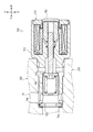
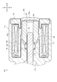
- valve device 100 will be described using FIGS. 2 to 4.
- the valve device 100 controls the amount of oil (the amount of oil) sent to the downstream side (in the present embodiment, the piston jet 16).
- the valve device 100 mainly includes a housing 110, an inflow portion 120, a partition portion 130, a valve 140, a spring 150, a solenoid portion 160, and a plug 170.
- the valve device 100 is configured to be switchable between an open valve state which permits oil to be sent downstream and a closed valve state which regulates that oil is sent downstream.
- an open valve state which permits oil to be sent downstream
- a closed valve state which regulates that oil is sent downstream.
- the housing 110 shown in FIGS. 2 to 4 accommodates various members constituting the valve device 100.
- the housing 110 is formed in a substantially cylindrical shape.
- the housing 110 is disposed with the axial direction directed in the front-rear direction.
- the housing 110 includes a through hole 111, an outlet hole 112 and a drain hole 113.
- the through hole 111 shown in FIGS. 3 and 4 is a hole that penetrates the housing 110 in the axial direction (front-rear direction).
- the through hole 111 is formed such that the axis thereof overlaps with the housing 110.
- the through hole 111 includes a concave portion 114, a step portion 115, a throttle portion 116 and a through hole tapered portion 117.
- the concave portion 114 shown in FIG. 3 is a portion formed in a concave shape in the outer diameter direction from the inner peripheral surface of the through hole 111.
- the recess 114 is formed at the front end of the through hole 111.
- the recess 114 is formed along the circumferential direction of the through hole 111.
- the stepped portion 115 shown in FIG. 3 is a stepped portion (stepped portion).
- the stepped portion 115 is formed slightly ahead of the substantially central portion in the front-rear direction of the through hole 111.
- the stepped portion 115 is formed with its wall face forward.
- the narrowed portion 116 shown in FIG. 4 is a portion formed with a small inner diameter.
- the throttling portion 116 is formed slightly behind the substantially central portion in the front-rear direction of the through hole 111.
- the throttling portion 116 is formed so that the inner diameter is smaller than that of the other portion (the front and rear portion of the throttling portion 116).
- the throttling portion 116 is formed so that the axis line overlaps the through hole 111.
- the through hole tapered portion 117 shown in FIG. 4 is a portion formed in a tapered shape.
- the through hole tapered portion 117 is formed at the rear of the through hole 111 (rearward than the narrowed portion 116).
- the through hole tapered portion 117 is formed in a tapered shape by reducing its diameter as it goes from the rear to the front (as it approaches the narrowed portion 116).
- the through hole tapered portion 117 is formed so that the axis thereof overlaps with the through hole 111.
- the outflow hole 112 shown in FIG. 3 is a hole penetrating the peripheral wall of the housing 110 in the radial direction.
- the outflow hole 112 is formed at the front end (one end in the axial direction) of the housing 110. More specifically, the outflow hole 112 is disposed between the recess 114 and the step 115 in the front-rear direction.
- the outflow hole 112 communicates the inside and the outside of the housing 110.
- the outflow hole 112 is formed in a shape extending in the circumferential direction of the housing 110.
- Two outflow holes 112 are provided in the upper and lower portions of the housing 110.
- the outflow holes 112 allow the oil inside the housing 110 to flow out (more specifically, downstream of the oil passage 15), as described later.
- the two outflow holes 112 are communicated with each other outside the housing 110 via a spiral groove 112 a formed along the circumferential direction on the outer peripheral surface of the housing 110.
- the drain hole 113 shown in FIG. 3 is a hole which penetrates the peripheral wall of the housing 110 in the radial direction.
- the drain hole 113 is disposed at a substantially central portion in the front-rear direction of the housing 110. More specifically, the drain hole 113 is disposed between the stepped portion 115 and the narrowed portion 116 in the front-rear direction.
- the drain hole 113 communicates the inside and the outside of the housing 110.
- Two drain holes 113 are provided in the upper and lower portions of the housing 110.
- the drain hole 113 drains the oil inside the housing 110 to the outside (more specifically, the oil pan), as described later.
- the two drain holes 113 communicate with each other outside the housing 110 via a pot-shaped groove 113 a formed along the circumferential direction on the outer peripheral surface of the housing 110.
- the inflow part 120 shown in FIG.2 and FIG.3 is a plate-shaped member formed in substantially annular shape.
- the outer diameter of the inflow portion 120 is formed to be substantially the same as the outer diameter of the recess 114 of the through hole 111.
- the inflow portion 120 is fitted in the recess 114.
- the inflow portion 120 is attached to the housing 110 with the plate surface directed in the front-rear direction.
- the inflow part 120 is arrange
- the inflow portion 120 includes an inflow hole 121.
- the inflow hole 121 shown in FIG. 3 is a hole which penetrates the inflow part 120 in the front-rear direction.
- the inflow hole 121 is formed substantially at the center of the inflow portion 120 in a side sectional view.
- the inflow holes 121 communicate the inside and the outside of the housing 110.
- the diameter of the inflow hole 121 is formed smaller than the outer diameter of the front wall portion 142 of the valve 140 described later.
- the inflow hole 121 is formed so that the axis line overlaps the through hole 111.
- the inflow holes 121 allow the oil outside the housing 110 to flow into the interior (a space R1 described later), as described later.
- a predetermined space (space R1) partitioned in the front-rear direction by the inflow portion 120 and the partition portion 130 described later is formed at the front of the through hole 111.
- One end (upstream end) of the outflow hole 112 is connected to the space R1.
- a predetermined space (space R2) partitioned in the front-rear direction by the partition 130 and the throttling part 116 is formed in a substantially central portion in the front-rear direction of the through hole 111 adjacent to the rear of the space R1.
- One end (upstream end) of the drain hole 113 is connected to the space R2.
- the partition part 130 shown in FIGS. 2 and 3 is a member that divides the inside of the housing 110. Specifically, the partition 130 divides the inside of the housing 110 into the space R1 and the space R2 adjacent in the front-rear direction as described above.
- the partition 130 is formed in a substantially cylindrical shape.
- the partition portion 130 is disposed with the axial direction directed in the front-rear direction.
- the rear of the partition 130 is formed to have an outer diameter larger than that of the front.
- the outer diameter of the rear portion of the partition 130 is formed to be substantially the same as the inner diameter of the step portion 115 of the through hole 111 immediately in front of it.
- the partition portion 130 is disposed in front of the stepped portion 115, and is fixed to the housing 110 in a state of being in contact with the stepped portion 115 in the front-rear direction.
- the partition 130 includes a partition through hole 131.
- the partition through holes 131 shown in FIG. 3 are holes penetrating the partition 130 in the front-rear direction.
- the partition through hole 131 is formed substantially at the center of the partition 130 in a side cross sectional view.
- the partition wall through holes 131 communicate the front side and the rear side of the partition portion 130 (that is, the space R1 and the space R2).
- the partition through hole 131 includes a partition taper portion 132.
- the detailed description about the structure of the partition through-hole 131 is mentioned later.
- the partition taper portion 132 shown in FIG. 3 is a portion of the partition wall through hole 131 formed in a tapered shape.
- the partition taper portion 132 is formed at the rear of the partition through hole 131.
- the partition taper portion 132 is formed in a tapered shape by reducing its diameter in the forward direction from the rear end.
- the partition taper portion 132 is formed so that the axis line overlaps with the through hole 111.
- the valve 140 shown in FIGS. 2 and 3 is formed to be capable of reciprocating in the front-rear direction.
- the valve 140 includes a tubular portion 141 and a front wall portion 142.
- the cylindrical portion 141 shown in FIG. 3 is a member formed in a substantially cylindrical shape.
- the cylindrical portion 141 is disposed with the axial direction directed in the front-rear direction.
- the outer diameter of the cylindrical portion 141 is formed to be substantially the same as the inner diameter of the through hole 111 (specifically, the portion that divides the space R1).
- the inner diameter of the cylindrical portion 141 is formed to be slightly larger than the inner diameter of the inflow hole 121.
- the length in the front-rear direction of the cylindrical portion 141 is formed to be slightly shorter than the length between the outflow hole 112 and the partition 130 in the front-rear direction.
- the cylindrical portion 141 has an outer peripheral groove 143.
- the outer peripheral groove 143 shown in FIG. 3 is a portion (groove) formed in a concave shape in the inner diameter direction from the outer peripheral surface of the cylindrical portion 141.
- the outer peripheral groove 143 is formed at the front of the cylindrical portion 141.
- the length (width) of the outer circumferential groove 143 in the front-rear direction is slightly longer than the length (diameter) of the outflow hole 112 in the front-rear direction.
- the outer peripheral groove 143 is formed in a substantially annular shape along the circumferential direction of the cylindrical portion 141.
- the front wall portion 142 shown in FIG. 3 is a plate-like member formed in a substantially annular shape.
- the front wall portion 142 is formed to cover the front side of the cylindrical portion 141.
- the front wall portion 142 is disposed with the plate surface facing in the front-rear direction.
- the front wall portion 142 includes a front wall inflow hole 144.
- the front wall inflow hole 144 shown in FIG. 3 is a hole which penetrates the front wall portion 142 in the front-rear direction.
- the front wall inflow hole 144 communicates the front side and the rear side of the valve 140 (more specifically, the front wall portion 142). That is, the front wall inflow hole 144 establishes communication between an oil flow space R1b to be described later in the space R1 and the hydraulic control space R1a. A detailed description of the configuration of the front wall inflow hole 144 will be described later.
- the valve 140 is formed in a bottomed cylindrical shape in which the front side is closed and the rear side is opened by the cylindrical portion 141 and the front wall portion 142.
- the valve 140 is disposed in the space R1 with the axial direction directed in the front-rear direction.
- the valve 140 is formed so that the axis line overlaps with the through hole 111.
- the valve 140 is configured to be reciprocally movable in the front-rear direction with respect to the space R1.
- the valve 140 In the open state, as shown in FIG. 3, the valve 140 is disposed at the most rearward position. When the valve 140 is disposed at the rearmost position (when the valve is in the open state), the valve 140 abuts on the partition 130. Further, the front end portion (front wall portion 142) of the valve 140 is disposed behind the outflow hole 112 in the front-rear direction.
- valve 140 is configured such that the inside of the space R1 is a space behind the front wall 142 (a space inside the valve 140) and a space ahead of the front wall 142 (a space outside the valve 140); Divide into below, the space inside valve
- the oil circulation space R1b is a space connected to the outflow hole 112.
- the hydraulic control space R1a is a space not connected to the outflow hole 112.
- the spring 150 shown in FIGS. 2 and 3 is a metal compression coil spring.
- the spring 150 is disposed inside the valve 140 (inside the hydraulic control space R1a) in a compressed state. More specifically, the spring 150 is disposed between the front wall 142 of the valve 140 and the bulkhead 130. Thus, the spring 150 always biases the valve 140 forward.
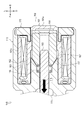
- the solenoid section 160 shown in FIGS. 2 and 4 is for moving the valve 140.
- the solenoid unit 160 is formed at the rear of the housing 110.
- the solenoid unit 160 includes a case 161, a bobbin 162, a coil 163, a plunger 164, a shaft 165, and a spring 166.
- the case 161 shown in FIG. 4 accommodates various members constituting the solenoid unit 160.
- the case 161 includes a first case 161a and a second case 161b.
- the first case 161a is formed in a substantially cylindrical shape whose rear end is closed.
- the second case 161 b is formed in a substantially cylindrical shape outside the first case 161 a.
- the first case 161a and the second case 161b are connected to each other and integrally formed.
- the bobbin 162 shown in FIG. 4 is a member formed in a substantially cylindrical shape.
- the bobbin 162 is housed inside the second case 161 b of the case 161.
- the bobbin 162 has flanges extending radially outward at the front end and the rear end.
- the coil 163 shown in FIG. 4 is formed of a copper wire.
- the coil 163 is fitted on the outer peripheral surface of the bobbin 162.
- the coil 163 is connected to a power supply (not shown).
- the coil 163 can generate a magnetic field by the current from the power supply.
- the plunger 164 shown in FIG. 4 is a member formed in a substantially cylindrical shape.
- the plunger 164 is disposed at the rear of the through hole 111 (more specifically, at a portion rearward of the narrowed portion 116) and inside the coil 163.
- the rear of the plunger 164 is housed inside the first case 161 a of the case 161.
- the plunger 164 is formed so that the axis line overlaps with the through hole 111.
- Plunger 164 is arranged to be able to reciprocate in the front-rear direction. When a magnetic field is generated by the coil 163, the plunger 164 is attracted and slides forward of the rear of the through hole 111.
- the plunger 164 comprises a plunger taper 167.
- the plunger tapered portion 167 shown in FIG. 4 is a portion formed in a tapered shape.
- Plunger taper portion 167 is formed on the outer peripheral surface of the front of plunger 164.
- the plunger tapered portion 167 is formed in a tapered shape by reducing its diameter as it goes from the rear to the front (front end).
- Plunger tapered portion 167 is formed to be an inclined surface extending along substantially the same direction as through hole tapered portion 117 in a side sectional view.
- the plunger 164 In the open state, as shown in FIG. 4, the plunger 164 is disposed at the rearmost position of the rear of the through hole 111.
- the rear end of the plunger 164 is in contact with the rear end of the first case 161a.
- the plunger taper portion 167 of the plunger 164 is separated from the through hole taper portion 117 of the through hole 111.
- the shaft 165 shown in FIGS. 3 and 4 is a substantially cylindrical member.
- the shaft 165 is disposed with the axial direction directed in the front-rear direction.
- a substantially central portion in the front-rear direction of the shaft 165 is disposed inside the narrowed portion 116 of the through hole 111.
- the outer diameter of the shaft 165 is substantially the same as the inner diameter of the narrowed portion 116 of the through hole 111.
- the shaft 165 is slidably supported in the front-rear direction by the narrowed portion 116.
- the rear end of the shaft 165 is disposed at the rear of the through hole 111 and fixed to the plunger 164.
- the shaft 165 is configured to be slidable back and forth with the sliding of the plunger 164.
- the front end portion of the shaft 165 is formed in a curved shape that is convex toward the front.
- the front end of the shaft 165 is always disposed in the space R2 regardless of the sliding of the shaft 165.
- the front end portion of the shaft 165 is formed to face the partition taper portion 132 of the partition portion 130 in the front-rear direction.
- the front end portion of the shaft 165 is disposed in a state (opened state) separated from the partition taper portion 132 of the partition 130 in the front-rear direction.
- the spring 166 shown in FIG. 4 is a metal compression coil spring.
- the spring 166 is disposed between the throttle portion 116 and the plunger 164 in a compressed state.
- the spring 166 always biases the plunger 164 rearward.
- the plunger 164 In the open state, the plunger 164 is disposed at the most rearward position (the rear end of the plunger 164 is in contact with the rear end of the first case 161a) by the biasing force of the spring 166. Be done.
- the plug 170 shown in FIGS. 2 and 4 is a member formed in a substantially annular shape.
- the plug 170 is disposed with the axial direction directed in the front-rear direction.
- the plug 170 is pressed into the housing 110 from the rear, and is caulked and fixed by the housing 110.
- the plug 170 is thereby attached to the housing 110.
- the plug 170 supports the solenoid portion 160 from the rear and closes the through hole 111 from the rear.
- the valve device 100 configured as described above is disposed in the oil passage 15, as shown in FIG. Specifically, in a state where the front portion of the valve device 100 is inserted in the middle of the oil passage 15, the valve device 100 is referred to as a predetermined wall portion provided with the oil passage 15 (hereinafter referred to as "wall portion 200" Attached to). In the following, a portion of the oil passage 15 disposed upstream of the valve device 100 will be referred to as an upstream passage 15 a. Further, a portion of the oil passage 15 disposed downstream of the valve device 100 (on the side of the piston jet 16) is referred to as a downstream passage 15b.
- the downstream (rear) end of the upstream passage 15 a is connected to the front end of the housing 110 of the valve device 100.
- the inflow portion 120 is disposed.
- the inflow holes 121 of the inflow portion 120 communicate the inside (more specifically, the space R1) of the housing 110 with the outside as described above. That is, the upstream side passage 15 a and the space R 1 are in communication via the inflow hole 121 of the inflow portion 120.
- the upstream (lower) end of the downstream passage 15 b is connected to the front upper portion of the housing 110 of the valve device 100.
- one (upper side) outlet holes 112 of the two outlet holes 112 provided in total are disposed.
- the outflow hole 112 communicates the inside (space R1) of the housing 110 with the outside as described above. That is, the downstream side passage 15 b and the space R 1 are in communication via the outflow hole 112.
- the upstream passage 15a (the oil passage 15), the space R1 of the valve device 100, and the downstream passage 15b (the oil passage 15) are in communication with each other.
- the upstream (upper) end of the drain passage 210 formed in the wall portion 200 is connected to the substantially central lower portion of the housing 110 of the valve device 100. Be done.
- one (lower) drain hole 113 of the two drain holes 113 is disposed.
- the drain hole 113 communicates the inside (space R2) of the housing 110 with the outside as described above. That is, the space R2 of the valve device 100 and the drain passage 210 communicate with each other through the drain hole 113.
- the valve device 100 When the valve device 100 is disposed in the oil passage 15, the other (lower) outflow hole 112 of the two provided outflow holes 112 and the other (upper side) of the two provided drain holes 113
- the wall surface of the wall portion 200 is disposed in a portion facing the drain hole 113 of the second embodiment.
- the oil that has flowed out of the lower outlet hole 112 to the outside of the housing 110 is circulated to the one (upper) outlet hole 112 side via the head groove 112a.
- the oil flowing out of the lower outflow hole 112 is circulated to the downstream side passage 15b together with the oil flowing out of the upper outflow hole 112.
- the oil that has flowed out of the upper drain hole 113 to the outside of the housing 110 is circulated to the one (lower) drain hole 113 side via the head groove 113a.
- the oil flowing out of the upper drain hole 113 is circulated to the drain passage 210 together with the oil flowing out of the lower drain hole 113.
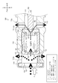
- a space (space R1) adjacent to the inflow portion 120 is a space (a space outside the valve 140) in front of the front wall portion 142. That is, the oil that has flowed into the space R1 through the inflow hole 121 flows into the oil circulation space R1b of the space R1.
- part of the oil flowing into the oil circulation space R1b flows into the inside of the valve 140 (the hydraulic pressure control space R1a) through the front wall inflow hole 144.
- the shaft 165 is disposed in a state of being separated from the partition taper portion 132. That is, the hydraulic control space R1a and the space R2 are in communication with each other through the shaft 165 and the partition taper portion 132. Therefore, the oil that has flowed into the hydraulic control space R1a flows into the space R2.
- the oil flowing into the space R2 is drained to the outside through the drain hole 113.
- the hydraulic pressure (hydraulic pressure P 2 described later) in the hydraulic control space R1a is smaller than the hydraulic pressure (hydraulic pressure P 1 described later) supplied from the upstream passage 15a.
- hydraulic pressure supplied oil pressure supplied
- hydraulic P 1 supplied from the upstream side passage 15a referred to a load that acts on the valve 140 by the hydraulic pressure P 1 and the load F p1.
- the load F p1 acts to press the valve 140 rearward.
- the pressure inside the oil in the hydraulic control space R1a (control space pressure) called hydraulic P 2, referred to the load acting on the valve 140 by the hydraulic pressure P 2 and the load F p2.
- the load F p2 acts to push the valve 140 forward.
- a load acting on the valve 140 by the spring 150 is referred to as a load F sp .
- the load F sp acts to push the valve 140 forward.
- valve 140 When the relationship of Formula 1 is satisfied, the valve 140 is positioned at the rear of the slidable range, and this position is maintained.
- valve device 100 drains some of the supplied oil, while sending the remaining oil to the downstream side (piston jet 16).
- valve 140 in the valve device 100 the flow state of oil, and the load acting on the valve 140 when switching from the open state to the closed state will be described using FIGS. 6 to 8.
- the hydraulic pressure P 2 inside the hydraulic control chamber R1a is likely to rise.
- the hydraulic pressure P 2 inside the hydraulic control space R1a consists hydraulic P 1 supplied from the upstream side passage 15a and substantially the same.
- the interior of the hydraulic P 2 of the hydraulic control space R1a is becomes substantially equal to the pressure P 1 supplied from the upstream side passage 15a, the oil pressure P 1 and the load F p1 acting on the valve 140
- the load F p2 acting on the valve 140 by the hydraulic pressure P 2 and the load F sp acting on the valve 140 by the spring 150 satisfy the relationship of the following formula 2, the valve 140 can slide within a range Start sliding from the rearmost position of the.
- valve 140 slides forward in a state in which the relationship of the equation 2 is satisfied, the valve 140 is at the front of the slidable range (the position where the front wall portion 142 of the valve 140 abuts the inflow portion 120). As well as being located, this position is maintained.
- the space adjacent to the inflow portion 120 has no space forward of the front wall portion 142 (space outside the valve 140), It is a space behind the front wall 142 (a space inside the valve 140). That is, when the valve is closed, the oil flow space R1b disappears in the space R1, and only the hydraulic control space R1a exists.
- the hydraulic pressure control space R1a is a space not connected to the outflow hole 112. That is, the oil flowing through the upstream passage 15a does not flow out to the downstream passage 15b.
- valve device 100 when the valve opening state is switched to the valve closing state (in the valve closing state), the valve device 100 does not drain the supplied oil and also sends it to the downstream side (piston jet 16). Absent.
- valve 140 in the valve device 100, the flow state of oil, and the load acting on the valve 140 when switching from the closed state to the open state will be described.
- the hydraulic pressure P 2 inside the oil in the hydraulic control space R1a becomes smaller than the hydraulic pressure P 1 supplied from the upstream side passage 15a, and the load F p1 acting on the valve 140 by the hydraulic P 1, the pressure P 2
- the load F p2 acting on the valve 140 and the load F sp acting on the valve 140 by the spring 150 satisfy the relationship of Formula 1 as described above.
- valve 140 is positioned at the rear of the slidable range after being slid rearward, and this position is maintained.
- a space (an oil circulation space R1b) in front of the front wall 142 is formed as a space adjacent to the inflow portion 120 along with the movement of the valve 140 to the rear. That is, with the movement of the valve 140 to the rear, the inflow hole 121 is in communication with the outflow hole 112 via the oil circulation space R1b. Thus, part of the oil flowing into the oil circulation space R1b (oil other than the oil flowing into the hydraulic pressure control space R1a) flows out to the downstream passage 15b via the outflow hole 112.
- valve device 100 drains some of the supplied oil while the remaining oil is Send to the piston jet 16).
- a predetermined temperature for example, 50 degrees
- the internal pressure P 2 of the hydraulic control chamber R1a is hardly lowered, made by the oil pressure P 2 less likely to reduce the load F p2 acting on the valve 140. That is, the load F p1 acting on the valve 140 by the hydraulic pressure P 1, the load F p2 acting on the valve 140 by the hydraulic pressure P 2, and the load F sp acting on the valve 140 by the spring 150 are It becomes difficult to satisfy the relationship of Specifically, since the pressure (valve back pressure) inside the hydraulic control space R1a is maintained high, a high pressure (oil pressure P 1 ) is required as a pressure (opening pressure) required to slide the valve 140 backward. ) Will be required.
- the predetermined configuration includes the configuration of the partition through hole 131 of the partition 130 and the front wall inlet 144 of the valve 140.
- FIG.3 and FIG.9 (a) the structure of the partition through-hole 131 of the partition part 130 is demonstrated in detail using FIG.3 and FIG.9 (a).
- the partition through holes 131 are holes penetrating the partition 130 in the front-rear direction as described above.
- the partition through hole 131 is formed so that the axis thereof overlaps with the through hole 111.
- the partition through holes 131 are formed in a substantially circular shape in a front view.
- the partition through hole 131 is formed substantially at the center of the partition 130 in a front view.
- the hole length (distance in the front-rear direction), the hole diameter (diameter) and the area of the partition wall through hole 131 are appropriately set in consideration of the operation of the valve 140.
- the partition through holes 131 are set as the hole length L2, the hole diameter D2, and the area A2.
- the hole length L2 is the length of a part of the partition wall through hole 131 excluding the part having a large opening (i.e., the partition taper part 132).
- the front wall inflow hole 144 is a hole which penetrates the front wall portion 142 in the front-rear direction as described above.
- the front wall inflow hole 144 is formed in a substantially circular shape in a front view.
- the front wall inflow hole 144 is formed smaller in area than the partition through hole 131.
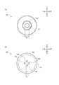
- Four front wall inflow holes 144 are provided as shown in FIG. Thus, the number (four) of the front wall inflow holes 144 is larger than the number (one) of the partition through holes 131.
- the four front wall inlets 144 are formed in the same size and shape as one another.
- the four front wall inflow holes 144 are formed in the vicinity of the approximate center of the front wall portion 142 in a front view.
- the four front wall inflow holes 144 are formed at positions corresponding to the apexes of the square in a front view.
- the four front wall inflow holes 144 are formed such that the axes thereof are parallel to the through holes 111, respectively.
- the hole length (distance in the front-rear direction), the hole diameter (diameter) and the total area (total area of the four front opening areas) of the four front wall inflow holes 144 are the valve 140 It is set appropriately in consideration of the operation of In the present embodiment, the front wall inflow hole 144 is set as the hole length L1 and the hole diameter D1. Further, the four front wall inflow holes 144 are set as the total area A1.
- Equation 3 (Number 3) Hole diameter D1 of front wall inflow hole 144 ⁇ hole diameter D2 of partition wall through hole 131
- the relationship between the hole diameter D1 of the front wall inlet hole 144 and the hole diameter D2 of the partition through hole 131 is such that the hole diameter D1 of the front wall inlet hole 144 is smaller than the hole diameter D2 of the partition through hole 131 It is set. Such a setting makes it possible to increase the oil passage resistance to the oil flowing through the front wall inflow hole 144 more than the oil passage resistance to the oil flowing through the partition through hole 131.
- Equation 4 (Number 4) Total area A1 of four partition wall through holes 131 ⁇ area A2 of front wall inflow holes 144
- the mutual area of the total area A1 of the four front wall inflow holes 144 and the area A2 of the partition through holes 131 is the same as the total area A1 of the four front wall inflow holes 144 is the area A2 of the partition through holes 131 It is set to be smaller than that. Such a setting makes it possible to increase the oil passage resistance to the oil flowing through the four front wall inflow holes 144 more than the oil passage resistance to the oil flowing through the partition through holes 131.
- the total area A1 of the four front wall inflow holes 144 is a plurality of partition through holes 131 Is set to be smaller than the total area (total area) of the area A2.
- a plurality of (four) front wall inflow holes 144 are provided. Further, the relationship between the hole diameter D1 of the front wall inflow hole 144 and the hole diameter D2 of the partition through hole 131 is defined by Equation 3 as described above. Further, the relationship between the total area A1 of the four front wall inflow holes 144 and the area A2 of the partition through holes 131 is defined by Equation 4 as described above.
- the oil passage resistance to the oil flowing through the four front wall inflow holes 144 can be increased more than the oil passage resistance to the oil flowing through the partition through holes 131.
- the amount of oil flowing into the hydraulic control space R1a is reduced. Then, if the amount of oil flowing into the hydraulic pressure control space R1a decreases, the oil in the hydraulic pressure control space R1a does not easily drain (even if the drained amount decreases), the hydraulic pressure hydraulic P 2 inside the control space R1a is easily lowered.
- the hydraulic pressure P 2 inside the hydraulic control space R1a is lowered, the load F p1 or the like that acts on the valve 140 by the hydraulic P 1 would meet the relationship such as described above formula 1. That is, even when the viscosity of the oil is high, when the shaft 165 is separated from the partition taper portion 132, the valve 140 can be appropriately slid rearward. That is, even when the viscosity of the oil is high, switching from the valve closing state to the valve opening state can be appropriately performed.
- the oil flowing through the four front wall inflow holes 144 becomes less susceptible to the influence of the oil passage resistance. That is, when the viscosity of the oil is low, even if the number of the front wall inflow holes 144 is defined by the equation 3 or the like (the area of the front wall inflow holes 144 is reduced compared to the prior art) Even if it has the configuration), it is difficult to reduce the amount of oil flowing into the hydraulic control space R1a. Therefore, when the viscosity of the oil is low, it does not decrease the amount of oil flowing into the hydraulic control space R1a, whereby it is possible to pressure P 2 of the inside of the hydraulic control space R1a is prevented from being lowered.
- the valve device 100 is: An inflow hole 121 provided on the front side (one side in the axial direction) to allow oil to flow into the inside, and provided on the rear side (the other side in the axial direction) further than the inflow hole 121 to allow oil to flow out A cylindrical housing 110 having an outlet hole 112; A space R1 (first space) separated from the inflow hole 121 and provided on the rear side (the other side) and connected to the outflow hole 112 between the inflow hole 121 and the space R1 is also provided.
- a partition 130 having a partition through hole 131 (partition communication hole) capable of communicating the (first space) with the outside;
- a solenoid section 160 (opening / closing means) capable of opening / closing the partition through hole 131 (section communication hole);
- a hydraulic control space R1a (second space) is defined between the space R1 (first space) and the partition 130 while being reciprocably provided in the back and forth direction (the axial direction) in the space R1 (first space)
- a valve 140 having four (at least two or more) front wall inflow holes 144 (valve communication holes) capable of communicating the inflow hole 121 with the hydraulic pressure control space R1a (second space);
- a spring 150 biasing means for biasing the valve 140 toward the front side (one side in the axial direction); Equipped with A valve device 100 that can switch between an open state and a closed state, In the case of the valve closing state, The partition wall through hole 131 (partition portion communicating hole) is closed by the solenoid portion 160 (opening and closing means), The spring 150
- the hole diameter D1 of the front wall inflow hole 144 (valve communication hole) is smaller than the hole diameter D2 of the partition through hole 131 (division part communication hole).
- the total area A1 of the front wall inflow holes 144 (valve communication holes) is smaller than the (total) area A2 of the partition through holes 131 (partition portion communication holes).
- the oil path resistance to the oil flowing through the four front wall inflow holes 144 can be increased, and accordingly, the switching between the valve opening state and the valve closing state can be appropriately performed. Can.
- Space R1 is an embodiment of the first space.
- the hydraulic control space R1a is an embodiment of the second space.
- the partition part 130 is one form of embodiment of a division part.
- the partition wall through hole 131 is an embodiment of the partition communication hole.
- the front wall inflow hole 144 is an embodiment of the valve communication hole.
- the spring 150 is an embodiment of the biasing means.
- the solenoid unit 160 is an embodiment of the opening and closing means.
- valve device 100 is provided in the passage (oil passage 15) for supplying the oil to the piston jet 16, the other lubrication unit (oiling with oil) (for example, it may be provided in a passage for supplying oil to a cam or the like.
- valve apparatus 100 which concerns on this embodiment shall control supply of the oil of the engine 1, it is not limited to this.
- the type of fluid controlled by the valve device 100 may be a liquid such as water other than oil or a gas such as steam.
- valve device 100 closes the valve when the current is supplied to the coil 163 (during energization) and opens when the current is not supplied to the coil 163 (during non-energization).
- valve state is to be switched to, it is not limited to this.
- the valve device 100 opens the valve when the current is supplied to the coil 163 (when energized), and switches the valve closing state when the current is not supplied to the coil 163 (when not energized). It may be
- the spring 150 is a metal compression coil spring, it is not limited to this.
- the spring 150 (biasing means) may be, for example, an elastic body such as rubber as long as it biases the valve 140.
- valve apparatus 100 (opening / closing means) which concerns on this embodiment shall open / close the partition through-hole 131 by the solenoid part 160, it is not limited to this.
- a plurality (four) of the front wall inflow holes 144 of the valve 140 are provided, and the hole diameter D1 of the front wall inflow hole 144 and the hole diameter D2 of the partition through hole 131
- Equation 3 the relationship between the total area A1 of the four front wall inflow holes 144 and the area A2 of the partition through holes 131 is defined by Equation 4, these three It is not necessary to have all three configurations.
- a plurality of (four) front wall inflow holes 144 of the valve 140 are provided, and the relationship between the hole diameter D1 of the front wall inflow hole 144 and the hole diameter D2 of the partition through hole 131 Even if the relationship between the total area A1 of the four front wall inlet holes 144 and the area A2 of the partition through holes 131 is not defined by the equation 4, the four front walls are not defined by the equation 3.
- the oil passage resistance to the oil flowing through the inflow hole 144 can be increased.
- the front wall inflow holes 144 of the valve 140 are provided with a plurality (four) in number, and the relationship between the hole diameter D1 of the front wall inflow hole 144 and the hole diameter D2 of the partition through hole 131 Is defined by Equation 3, and even if the relationship between the total area A1 of the four front wall inflow holes 144 and the area A2 of the partition through holes 131 is not defined by the equation 4, four front wall inflows.
- the oil path resistance to the oil flowing through the holes 144 can be increased.
- the front wall inflow holes 144 of the valve 140 are provided with a plurality (four) in number, and the relationship between the hole diameter D1 of the front wall inflow hole 144 and the hole diameter D2 of the partition through hole 131 Even if the relationship between the total area A1 of the four front wall inflow holes 144 and the area A2 of the partition through holes 131 is not defined by the equation 3, the four front The oil passage resistance to the oil flowing through the wall inflow hole 144 can be increased.
- the configuration of the front wall inflow hole 144 of the valve 140 is not limited to that according to the present embodiment (the first embodiment). This will be described in detail below with reference to FIG.
- FIG. 10A is a front view showing a valve 140a according to the second embodiment.
- the number of front wall inflow holes 144a of the valve 140a may be nine instead of four as in the first embodiment. That is, the number of front wall inflow holes 144a may be two or more. Further, the arrangement of the front wall inflow holes 144a of the valve 140a may not be the positions corresponding to the apexes of the square in front view as in the first embodiment. That is, the arrangement of the front wall inflow holes 144a of the valve 140a can be set arbitrarily. Even with such a configuration, the oil passage resistance to the oil flowing through the front wall inflow hole 144a can be increased.
- Fig. 10 (b) is a front view showing a valve 140b according to the third embodiment.
- the shape of the front wall inflow hole 144b of the valve 140b may not be a circular shape in a front view as in the first embodiment, but may be a square shape in a front view. Even with such a configuration, the oil passage resistance to the oil flowing through the front wall inflow hole 144b can be increased.
- FIG. 10C is a front view showing a valve 140c according to the fourth embodiment.
- the shape of the front wall inflow hole 144c of the valve 140c may be a slit shape instead of a circular shape or a square shape in a front view as in the first embodiment or the third embodiment. Good. Even with such a configuration, the oil passage resistance to the oil flowing through the front wall inflow hole 144c can be increased.
- valve device 100 according to the second embodiment will be described.
- valve device 100 In the valve device 100 according to the second embodiment, the description of the same configuration as the valve device 100 according to the first embodiment will be omitted.
- the front wall portion 142 includes a front wall inflow hole 144 and a front wall cylindrical portion 145.
- the front wall inflow hole 144 shown in FIG. 11 is a hole which penetrates the front wall cylindrical part 145 mentioned later in the front-back direction.
- the front wall inlet hole 144 communicates the front side and the rear side of the valve 140 (more specifically, the front wall cylindrical portion 145 of the front wall portion 142). That is, the front wall inflow hole 144 establishes communication between an oil flow space R1b to be described later in the space R1 and the hydraulic control space R1a.
- a detailed description of the configuration of the front wall inflow hole 144 will be described later.
- the front wall cylindrical portion 145 shown in FIG. 11 is a member for forming the front wall inflow hole 144.
- a front wall inflow hole 144 is formed in the front wall cylindrical portion 145 inside.
- the front wall cylindrical portion 145 is disposed with the axial direction directed in the front-rear direction. A detailed description of the configuration of the front wall cylindrical portion 145 will be described later.
- the predetermined configuration for avoiding the occurrence of the problem as described above includes the partition wall through hole 131 of the partition portion 130 and the front wall inlet hole 144 of the valve 140 and the front.
- the configuration of the wall cylindrical portion 145 is included.
- FIG.11 and FIG.12 (a) the structure of the partition through-hole 131 of the partition part 130 is demonstrated in detail using FIG.11 and FIG.12 (a).
- the partition through holes 131 are holes penetrating the partition 130 in the front-rear direction as described above.
- the partition through hole 131 is formed so that the axis thereof overlaps with the through hole 111.
- the partition through holes 131 are formed in a substantially circular shape in a front view.
- the partition through hole 131 is formed substantially at the center of the partition 130 in a front view.
- the hole length (distance in the front-rear direction) and the hole diameter (diameter) of the partition wall through hole 131 are appropriately set in consideration of the operation of the valve 140.
- the partition through holes 131 are set as the hole length L2 and the hole diameter D2.
- the hole length L2 is the length of a part of the partition wall through hole 131 excluding the part having a large opening (i.e., the partition taper part 132).
- the front wall inflow hole 144 is a hole which penetrates the front wall cylindrical portion 145 in the front-rear direction as described above.
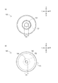
- the front wall inflow hole 144 is formed in a substantially circular shape in a front view.
- the front wall inflow hole 144 is formed smaller in area than the partition wall through hole 131.
- the front wall inlet hole 144 is formed substantially at the center of the front wall portion 142 in a front view.
- the front wall inlet 144 is formed to extend rearward from the front wall 142 of the valve 140.
- the front wall inflow hole 144 is formed so that the axis line overlaps with the through hole 111.
- the front wall cylindrical portion 145 is a member for forming the front wall inflow hole 144 as described above.
- the front wall cylindrical portion 145 is formed in a substantially cylindrical shape.
- the front wall cylindrical portion 145 is formed to extend rearward from the front wall portion 142 of the valve 140.
- the rear end portion of the front wall cylindrical portion 145 is disposed forward of the substantially central portion in the front-rear direction of the valve 140.
- the outer diameter of the front wall cylindrical portion 145 is smaller than the inner diameter of the cylindrical portion 141.
- a predetermined space for disposing the spring 150 is defined between the front wall cylindrical portion 145 and the cylindrical portion 141.
- the hole length (distance in the front-rear direction) and the hole diameter (diameter) of the front wall inflow hole 144 It is set appropriately in consideration of the operation of 140.
- the front wall inflow hole 144 is set as the hole length L1 and the hole diameter D1.
- Equation 3 (Number 3) Hole diameter D1 of front wall inflow hole 144 ⁇ hole diameter D2 of partition wall through hole 131
- the relationship between the hole diameter D1 of the front wall inlet hole 144 and the hole diameter D2 of the partition through hole 131 is such that the hole diameter D1 of the front wall inlet hole 144 is smaller than the hole diameter D2 of the partition through hole 131 It is set. Such a setting makes it possible to increase the oil passage resistance to the oil flowing through the front wall inflow hole 144 more than the oil passage resistance to the oil flowing through the partition through hole 131.
- Equation 4 the relationship between the hole length L1 and the hole diameter D1 of the front wall inflow hole 144 and the hole length L2 and the hole diameter D2 of the partition through hole 131 is defined by Equation 4 below. (Number 4) Hole length L1 / hole diameter D1 of front wall inflow hole 144> hole length L2 / hole diameter D2 of partition wall through hole 131
- the numerical value obtained by dividing the hole length L1 of the front wall inflow hole 144 by the hole diameter D1 of the front wall inflow hole 144 corresponds to the hole length L2 of the partition through hole 131 as the hole diameter D2 of the partition through hole 131 It is set to be larger than the value obtained by dividing by.
- the ratio of the hole length to the hole diameter of the front wall inflow hole 144 is set to be larger than that of the partition through hole 131.
- the oil passage resistance to the oil flowing through the front wall inflow hole 144 can be increased more than the oil passage resistance to the oil flowing through the partition through hole 131.
- Equation 5 (Number 5) Hole length L1 of front wall inflow hole 144> hole length L2 of partition wall through hole 131
- the hole length L1 of the front wall inflow hole 144 is the hole length of the partition through hole 131 It is set to be larger than L2.
- the oil path resistance to oil flowing through the front wall inflow hole 144 The oil passage resistance to oil flowing through the partition wall through hole 131 can be increased.
- the relationship between the hole diameter D1 of the front wall inlet hole 144 and the hole diameter D2 of the partition through hole 131 is defined by Equation 3 as described above. Further, the relationship between the hole length L1 and the hole diameter D1 of the front wall inflow hole 144 and the hole length L2 and the hole diameter D2 of the partition through hole 131 is defined by Equation 4 as described above. Further, the relationship between the hole length L1 of the front wall inflow hole 144 and the hole length L2 of the partition through hole 131 is defined by Equation 5 as described above.
- the oil passage resistance to the oil flowing through the front wall inflow hole 144 can be increased more than the oil passage resistance to the oil flowing through the partition through hole 131.
- the amount of oil flowing into the hydraulic control space R1a is reduced. Then, if the amount of oil flowing into the hydraulic pressure control space R1a decreases, the oil in the hydraulic pressure control space R1a does not easily drain (even if the drained amount decreases), the hydraulic pressure hydraulic P 2 inside the control space R1a is easily lowered.
- the hydraulic pressure P 2 inside the hydraulic control space R1a is lowered, the load F p1 or the like that acts on the valve 140 by the hydraulic P 1 would meet the relationship such as described above formula 1. That is, even when the viscosity of the oil is high, when the shaft 165 is separated from the partition taper portion 132, the valve 140 can be appropriately slid rearward. That is, even when the viscosity of the oil is high, switching from the valve closing state to the valve opening state can be appropriately performed.
- the oil flowing through the front wall inflow hole 144 becomes less susceptible to the influence of the oil path resistance. That is, when the viscosity of the oil is low, even if the number of the front wall inflow holes 144 is defined by the equation 3 or the like (the area of the front wall inflow holes 144 is reduced compared to the prior art) Even if it has the configuration), it is difficult to reduce the amount of oil flowing into the hydraulic control space R1a. Therefore, when the viscosity of the oil is low, it does not decrease the amount of oil flowing into the hydraulic control space R1a, whereby it is possible to pressure P 2 of the inside of the hydraulic control space R1a is prevented from being lowered.
- the valve device 100 As described above, the valve device 100 according to the second embodiment (in accordance with the second embodiment) An inflow hole 121 provided on the front side (one side in the axial direction) to allow oil to flow into the inside, and provided on the rear side (the other side in the axial direction) further than the inflow hole 121 to allow oil to flow out A cylindrical housing 110 having an outlet hole 112; A space R1 (first space) separated from the inflow hole 121 and provided on the rear side (the other side) and connected to the outflow hole 112 between the inflow hole 121 and the space R1 is also provided.
- a space R1 first space
- a partition 130 having a partition through hole 131 (partition communication hole) capable of communicating the (first space) with the outside;
- a solenoid section 160 (opening / closing means) capable of opening / closing the partition through hole 131 (section communication hole);
- a hydraulic control space R1a (second space) is defined between the space R1 (first space) and the partition 130 while being reciprocably provided in the back and forth direction (the axial direction) in the space R1 (first space)
- a valve 140 having a front wall inflow hole 144 (valve communication hole) capable of communicating the inflow hole 121 with the hydraulic pressure control space R1a (second space);
- a spring 150 biasing means for biasing the valve 140 toward the front side (one side in the axial direction); Equipped with A valve device 100 that can switch between an open state and a closed state, In the case of the valve closing state, The partition wall through hole 131 (partition portion communicating hole) is closed by the solenoid portion 160 (opening and closing means), The spring 150 (biasing means)
- the hole diameter D1 of the front wall inflow hole 144 (valve communication hole) is smaller than the hole diameter D2 of the partition through hole 131 (division part communication hole).
- the hole length L1 (length in the axial direction) of the front wall inflow hole 144 (valve communication hole) is the hole length L2 (length in the axial direction) of the partition through hole 131 (partition communication hole) It is longer than that.
- the oil path resistance to the oil flowing through the front wall inflow hole 144 can be increased, and accordingly, the switching between the valve opening state and the valve closing state can be appropriately performed.
- Space R1 is an embodiment of the first space.
- the hydraulic control space R1a is an embodiment of the second space.
- the partition part 130 is one form of embodiment of a division part.
- the partition wall through hole 131 is an embodiment of the partition communication hole.
- the front wall inflow hole 144 is an embodiment of the valve communication hole.
- the spring 150 is an embodiment of the biasing means.
- the solenoid unit 160 is an embodiment of the opening and closing means.
- valve device 100 is provided in the passage (oil passage 15) for supplying the oil to the piston jet 16, the other lubrication unit (oiling with oil) (for example, it may be provided in a passage for supplying oil to a cam or the like.
- valve apparatus 100 which concerns on this embodiment shall control supply of the oil of the engine 1, it is not limited to this.
- the type of fluid controlled by the valve device 100 may be a liquid such as water other than oil or a gas such as steam.
- valve device 100 closes the valve when the current is supplied to the coil 163 (during energization) and opens when the current is not supplied to the coil 163 (during non-energization).
- valve state is to be switched to, it is not limited to this.
- the valve device 100 opens the valve when the current is supplied to the coil 163 (when energized), and switches the valve closing state when the current is not supplied to the coil 163 (when not energized). It may be
- the spring 150 is a metal compression coil spring, it is not limited to this.
- the spring 150 (biasing means) may be, for example, an elastic body such as rubber as long as it biases the valve 140.
- valve apparatus 100 (opening / closing means) which concerns on this embodiment shall open / close the partition through-hole 131 by the solenoid part 160, it is not limited to this.
- the relationship between the hole diameter D1 of the front wall inflow hole 144 and the hole diameter D2 of the partition through hole 131 is defined by Equation 3, and the hole length L1 and the hole diameter D1 of the front wall inflow hole 144
- the relationship between the hole length L2 and the hole diameter D2 of the partition wall through hole 131 is defined by the equation 4, and the hole length L1 of the front wall inlet hole 144 and the hole length L2 of the partition wall through hole 131
- the relationship of is the configuration defined by Equation 5, it is not necessary to have all these three configurations.
- the relationship between the hole diameter D1 of the front wall inflow hole 144 and the hole diameter D2 of the partition through hole 131 is defined by Equation 3, and the hole length L1 and the hole diameter D1 of the front wall inlet hole 144 and the partition through hole 131
- the relationship between the hole length L2 and the hole diameter D2 of each other is defined by Equation 4, and the relationship between the hole length L1 of the front wall inflow hole 144 and the hole length L2 of the partition wall through hole 131 is Even if the configuration is not defined by the above, the oil passage resistance to the oil flowing through the front wall inflow hole 144 can be increased.
- the relationship between the hole diameter D1 of the front wall inflow hole 144 and the hole diameter D2 of the partition wall through hole 131 is defined by Equation 3, and the hole length L1 and the hole diameter D1 of the front wall inlet hole 144 and the partition wall through hole 131
- the relationship between the hole length L2 and the hole diameter D2 is not defined by Equation 4, and the relationship between the hole length L1 of the front wall inflow hole 144 and the hole length L2 of the partition wall through hole 131 is Even in the configuration defined by 5, it is possible to increase the oil passage resistance to the oil flowing through the front wall inflow hole 144.
- the relationship between the hole diameter D1 of the front wall inflow hole 144 and the hole diameter D2 of the partition wall through hole 131 is not defined by Formula 3, and the hole length L1 and the hole diameter D1 of the front wall inlet hole 144 and the partition wall through hole
- the mutual relationship between the hole length L2 and the hole diameter D2 of 131 is defined by the equation 4, and the mutual relationship between the hole length L1 of the front wall inflow hole 144 and the hole length L2 of the partition through hole 131 is Even in the configuration defined by 5, it is possible to increase the oil passage resistance to the oil flowing through the front wall inflow hole 144.
- the configuration of the front wall inflow hole 144 of the valve 140 is not limited to that according to the present embodiment (the first embodiment of the valve device 100 according to the second embodiment). This will be described in detail below with reference to FIG.
- FIG. 13 (a) is a front view showing a valve 140a according to the second embodiment.
- the number of front wall inflow holes 144a of the valve 140a may be more than one as in the first embodiment, but may be more than one. Also, in that case, the arrangement of the front wall inflow holes 144a of the valve 140a can be set arbitrarily. Even when such a configuration is combined with the configuration as described above (the configuration defined by Equations 3 to 5), the oil passage resistance to the oil flowing through the front wall inflow hole 144a can be increased.
- Fig. 13 (b) is a front view showing a valve 140b according to the third embodiment.
- the shape of the front wall inflow hole 144b of the valve 140b may not be a circular shape in a front view as in the first embodiment, but may be a square shape in a front view. Even in such a configuration, even when combined with the above-described configuration (configuration defined by Equations 3 to 5), the oil path resistance to oil flowing through the front wall inflow hole 144b is increased. Can.
- FIG. 13C is a front view showing a valve 140c according to the fourth embodiment.
- the shape of the front wall inflow hole 144c of the valve 140c may be a slit shape, not a circular shape or a square shape in a front view as in the first embodiment or the third embodiment. Good. Even with such a configuration, the oil passage resistance to the oil flowing through the front wall inflow hole 144c can be increased.
- the present invention can be applied to a valve device that can be switched between an open valve state and a closed valve state.
Landscapes
- Engineering & Computer Science (AREA)
- General Engineering & Computer Science (AREA)
- Mechanical Engineering (AREA)
- Chemical & Material Sciences (AREA)
- Combustion & Propulsion (AREA)
- Magnetically Actuated Valves (AREA)
Abstract
開弁状態と閉弁状態との切り替えを適切に行うことができるバルブ装置を提供する。 閉弁状態とする場合、ソレノイド部160により隔壁貫通孔131を閉鎖状態とし、流入孔121から流入するオイルの油圧によりバルブ140に作用する後側への荷重よりも、スプリング及び油圧制御空間R1a内のオイルの油圧によりバルブ140に作用する前側への合計荷重を大きくすることにより、バルブ140を前側へ移動させて流出孔112を閉鎖し、開弁状態とする場合、ソレノイド部160により隔壁貫通孔131を開放状態とし、流入孔121から流入するオイルの油圧によりバルブに作用する後側への荷重を、スプリング及び油圧制御空間R1a内のオイルの油圧によりバルブ140に作用する前側への合計荷重よりも大きくすることにより、バルブ140を後側へ移動させて流出孔112を開放し、前壁流入孔144は、4つ設けられる。
Description
本発明は、開弁状態と閉弁状態とに切り替え可能なバルブ装置の技術に関する。
従来、開弁状態と閉弁状態とに切り替え可能なバルブ装置の技術は公知となっている。例えば、特許文献1に記載の如くである。
特許文献1に記載のバルブ装置は、端面を有する略円筒状の油圧バルブと、オンとオフとを切り替え可能なソレノイドと、油圧バルブとソレノイドとの間に配置される隔壁と、を具備する。油圧バルブの端面と隔壁との間には、油圧を制御するための空間(油圧制御空間)が区画される。油圧バルブの端面には、油圧制御空間と外部とを連通するバルブ側連通孔が形成される。また、隔壁には、油圧制御空間とソレノイド側の空間とを連通する隔壁連通孔が形成される。また、ソレノイド側の空間には、オイルをドレインするためのドレイン孔が形成される。
特許文献1に記載のバルブ装置においては、ソレノイドをオンとオフとに切り替え、隔壁連通孔を開閉することにより、油圧制御空間内のオイルを、ソレノイド側の空間に流通させ、ドレイン孔からドレインさせる。こうして、バルブ装置においては、バルブ側連通孔から油圧制御空間内に流入するオイルを適宜にドレインし、当該油圧制御空間内の油圧を制御することによって油圧バルブを往復動させ、開弁状態と閉弁状態とに切り替えることができる。
しかしながら、特許文献1に記載の技術において、例えばオイルの温度が低い場合、オイルの粘度が高くなるため、隔壁連通孔を開放しても油圧制御空間内のオイルが適切にドレインしない場合がある。このような場合、油圧制御空間内の油圧を適切に制御できなくなり、ひいては開弁状態と閉弁状態との適切な切り替えが困難となる点で不利である。
本発明は以上の如き状況を鑑みてなされたものであり、その解決しようとする課題は、開弁状態と閉弁状態との切り替えを適切に行うことができるバルブ装置を提供することである。
本発明の解決しようとする課題は以上の如くであり、次にこの課題を解決するための手段を説明する。
本発明のバルブ装置は、軸線方向の一側に設けられてオイルを内部へ流入させる流入孔と、前記流入孔よりも前記軸線方向の他側に設けられてオイルを外部へと流出させる流出孔と、を有する筒状のハウジングと、前記流入孔に離間して前記他側に設けられ、前記流入孔との間に前記流出孔と接続される第一空間を区画すると共に、前記第一空間と外部とを連通可能な区画部連通孔を有する区画部と、前記区画部連通孔を開閉可能な開閉手段と、前記第一空間内に前記軸線方向へ往復動自在に設けられると共に前記区画部との間に第二空間を区画し、前記流入孔と前記第二空間とを連通可能な少なくとも2つ以上のバルブ連通孔を有するバルブと、前記バルブを前記軸線方向の一側へ向けて付勢する付勢手段と、を具備し、開弁状態と閉弁状態とに切り替え可能なバルブ装置であって、前記閉弁状態とする場合、前記開閉手段により前記区画部連通孔を閉鎖状態とし、前記流入孔から流入するオイルの油圧により前記バルブに作用する前記他側への荷重よりも、前記付勢手段及び前記第二空間内のオイルの油圧により前記バルブに作用する前記一側への合計荷重を大きくすることにより、前記バルブを前記一側へ移動させて前記流出孔を閉鎖し、前記開弁状態とする場合、前記開閉手段により前記区画部連通孔を開放状態とし、前記流入孔から流入するオイルの油圧により前記バルブに作用する前記他側への荷重を、前記付勢手段及び前記第二空間内のオイルの油圧により前記バルブに作用する前記一側への合計荷重よりも大きくすることにより、前記バルブを前記他側へ移動させて前記流出孔を開放するものである。
本発明のバルブ装置において、前記バルブ連通孔の前記軸線方向における長さを前記バルブ連通孔の径で除算して得られた数値は、前記区画部連通孔の前記軸線方向における長さを前記区画部連通孔の径で除算して得られた数値よりも大きいものである。
本発明のバルブ装置において、前記バルブ連通孔の径は、前記区画部連通孔の径よりも小さいものである。
本発明のバルブ装置において、前記バルブ連通孔の総面積は、前記区画部連通孔の総面積よりも小さいものである。
本発明のバルブ装置において、前記バルブ連通孔の前記軸線方向における長さは、前記区画部連通孔の前記軸線方向における長さよりも長いものである。
本発明の効果として、以下に示すような効果を奏する。
本発明のバルブ装置においては、開弁状態と閉弁状態との切り替えを適切に行うことができる。
以下では、図中の矢印U、矢印D、矢印F、矢印B、矢印L及び矢印Rで示した方向を、それぞれ上方向、下方向、前方向、後方向、左方向及び右方向と定義して説明を行う。
以下では、本発明の一実施形態(第一実施形態)に係るバルブ装置100について説明する。
まず、図1を参照してバルブ装置100が設けられるエンジン1の構成及びエンジン1におけるオイルの流れについて簡単に説明する。
エンジン1は、4つの気筒を具備する直列4気筒型である。エンジン1は、オイルポンプ11、オイルフィルタ12、メインギャラリ13、メインメタル/コンロッドメタル14、オイル通路15、ピストンジェット16、チェーンジェット17、チェーンテンショナー18、可変バルブタイミング機構(VVT)19、ラッシュアジャスタ(HLA)20、カムジャーナル21、カムシャワー22及びバルブ装置100を具備する。
オイルポンプ11は、オイルパン(不図示)に貯溜されたオイルを吸入すると共に、当該オイルを下流側へ圧送する。オイルポンプ11は、エンジン1によって当該エンジン1の回転数に応じた回転数で駆動される。オイルポンプ11の下流側には、オイルフィルタ12が配置される。オイルフィルタ12は、オイルから異物や不純物等を取り除く。
オイルフィルタ12を流通したオイルは、メインギャラリ13を流通する。メインギャラリ13を流通したオイルは、メインメタルやコンロッドメタル(メインメタル/コンロッドメタル14)へと送られる。メインメタル/コンロッドメタル14は、クランク軸(不図示)を支持する。
また、オイルフィルタ12を流通したオイルは、オイル通路15を流通する。オイル通路15を流通したオイルは、ピストンジェット16へと送られる。ピストンジェット16は、ピストン(不図示)にオイルを噴射する。また、オイル通路15におけるピストンジェット16の上流側には、バルブ装置100が配置される。バルブ装置100は、ピストンジェット16へと送られる油量を制御する。
また、オイルフィルタ12を流通したオイルは、適宜のオイル通路を流通して、チェーンジェット17、チェーンテンショナー18、可変バルブタイミング機構19、ラッシュアジャスタ20、カムジャーナル21及びカムシャワー22へと送られる。
以下では、図2から図4を用いて、バルブ装置100の構成について説明する。
バルブ装置100は、下流側(本実施形態においては、ピストンジェット16)へと送られるオイルの量(油量)を制御するものである。バルブ装置100は、主としてハウジング110、流入部120、隔壁部130、バルブ140、スプリング150、ソレノイド部160及びプラグ170を具備する。
なお、バルブ装置100は、オイルが下流側へと送られるのを許可する開弁状態と、オイルが下流側へと送られるのを規制する閉弁状態と、を切り替え可能に構成される。以下では、バルブ装置100が開弁状態であるものとして、各部材の配置や構成等の説明を行う。
図2から図4に示すハウジング110は、バルブ装置100を構成する種々の部材を収容するものである。ハウジング110は、略円筒状に形成される。ハウジング110は、軸線方向を前後方向へ向けて配置される。ハウジング110は、貫通孔111、流出孔112及びドレイン孔113を具備する。
図3及び図4に示す貫通孔111は、ハウジング110を軸線方向(前後方向)に貫通する孔である。貫通孔111は、ハウジング110と軸線が重複するように形成される。貫通孔111は、凹部114、段差部115、絞り部116及び貫通孔テーパ部117を具備する。
図3に示す凹部114は、貫通孔111の内周面から外径方向に凹状に形成された部分である。凹部114は、貫通孔111の前端部に形成される。凹部114は、貫通孔111の周方向に沿って形成される。
図3に示す段差部115は、段になっている部分(段差部分)である。段差部115は、貫通孔111の前後方向略中央部よりも若干前方に形成される。段差部115は、その壁面を前方へ向けて形成される。
図4に示す絞り部116は、内径が小さく形成された部分である。絞り部116は、貫通孔111の前後方向略中央部よりも若干後方に形成される。絞り部116は、その他の部分(当該絞り部116よりも前後方の部分)よりも内径が小さくなるように形成される。絞り部116は、貫通孔111と軸線が重複するように形成される。
図4に示す貫通孔テーパ部117は、テーパ状に形成された部分である。貫通孔テーパ部117は、貫通孔111の後部(絞り部116よりも後方)に形成される。貫通孔テーパ部117は、後方から前方に行くに従って(絞り部116に近接するに従って)縮径することにより先細り状に形成される。貫通孔テーパ部117は、貫通孔111と軸線が重複するように形成される。
図3に示す流出孔112は、ハウジング110の周壁を径方向に貫通する孔である。流出孔112は、ハウジング110の前側端部(軸線方向の一側端部)に形成される。より詳細には、流出孔112は、前後方向における凹部114と段差部115との間に配置される。流出孔112は、ハウジング110の内部と外部とを連通する。流出孔112は、ハウジング110の周方向へ延びたような形状に形成される。流出孔112は、ハウジング110の上部と下部とに2つ設けられる。流出孔112は、後述するように、ハウジング110の内部のオイルを外部(より詳細には、オイル通路15の下流側)へと流出させる。なお、2つの流出孔112は、ハウジング110の外周面に周方向に沿って形成された鉢巻溝112aを介して、当該ハウジング110の外部において連通される。
図3に示すドレイン孔113は、ハウジング110の周壁を径方向に貫通する孔である。ドレイン孔113は、ハウジング110の前後方向略中央部に配置される。より詳細には、ドレイン孔113は、前後方向における段差部115と絞り部116との間に配置される。ドレイン孔113は、ハウジング110の内部と外部とを連通する。ドレイン孔113は、ハウジング110の上部と下部とに2つ設けられる。ドレイン孔113は、後述するように、ハウジング110の内部のオイルを外部(より詳細には、前記オイルパン)へと流出(ドレイン)させる。なお、2つのドレイン孔113は、ハウジング110の外周面に周方向に沿って形成された鉢巻溝113aを介して、当該ハウジング110の外部において連通される。
図2及び図3に示す流入部120は、略円環状に形成された板状の部材である。流入部120の外径は、貫通孔111の凹部114の外径と略同一に形成される。流入部120は、凹部114に嵌合される。こうして、流入部120は、板面を前後方向へ向けた状態でハウジング110に取り付けられる。また、流入部120は、貫通孔111(ハウジング110)の前端部に配置される。流入部120は、流入孔121を具備する。
図3に示す流入孔121は、流入部120を前後方向に貫通する孔である。流入孔121は、側面断面視で流入部120の略中央に形成される。流入孔121は、ハウジング110の内部と外部とを連通する。流入孔121の径は、後述するバルブ140の前壁部142の外径よりも小さく形成される。流入孔121は、貫通孔111と軸線が重複するように形成される。流入孔121は、後述するように、ハウジング110の外部のオイルを内部(後述する空間R1)へと流入させる。
こうして、貫通孔111の前部には、流入部120と後述する隔壁部130とにより前後方向に区画された所定の空間(空間R1)が形成される。空間R1には、流出孔112の一端部(上流側端部)が接続されている。また、貫通孔111の前後方向略中央部には、隔壁部130と絞り部116とにより前後方向に区画された所定の空間(空間R2)が、空間R1の後方に隣接するように形成される。空間R2には、ドレイン孔113の一端部(上流側端部)が接続されている。
図2及び図3に示す隔壁部130は、ハウジング110の内部を区画する部材である。具体的には、隔壁部130は、ハウジング110の内部を、上述の如く前後方向に隣接する空間R1と空間R2とに区画する。隔壁部130は、略円筒状に形成される。隔壁部130は、軸線方向を前後方向へ向けて配置される。隔壁部130の後部は、前部よりも外径が大きくなるように形成される。隔壁部130の後部の外径は、貫通孔111の段差部115の直ぐ前方の内径と略同一に形成される。隔壁部130は、段差部115の前方に配置され、当該段差部115と前後方向に当接した状態でハウジング110に固定される。隔壁部130は、隔壁貫通孔131を具備する。
図3に示す隔壁貫通孔131は、隔壁部130を前後方向に貫通する孔である。隔壁貫通孔131は、側面断面視で隔壁部130の略中央に形成される。隔壁貫通孔131は、隔壁部130の前側と後側と(すなわち、空間R1と空間R2と)を連通する。隔壁貫通孔131は、隔壁テーパ部132を具備する。
なお、隔壁貫通孔131の構成についての詳細な説明は後述する。
なお、隔壁貫通孔131の構成についての詳細な説明は後述する。
図3に示す隔壁テーパ部132は、隔壁貫通孔131のうち、テーパ状に形成された部分である。隔壁テーパ部132は、隔壁貫通孔131の後部に形成される。隔壁テーパ部132は、後端部から前方に行くに従って縮径することにより先細り状に形成される。隔壁テーパ部132は、貫通孔111と軸線が重複するように形成される。
図2及び図3に示すバルブ140は、前後方向へ往復動自在に形成されるものである。バルブ140は、筒状部141及び前壁部142を具備する。
図3に示す筒状部141は、略円筒状に形成された部材である。筒状部141は、軸線方向を前後方向へ向けて配置される。筒状部141の外径は、貫通孔111(具体的には、空間R1を区画する部分)の内径と略同一に形成される。筒状部141の内径は、流入孔121の内径よりも若干大きく形成される。筒状部141の前後方向の長さは、前後方向において流出孔112と隔壁部130との間の長さよりも若干短く形成される。筒状部141は、外周溝143を具備する。
図3に示す外周溝143は、筒状部141の外周面から内径方向に凹状に形成された部分(溝)である。外周溝143は、筒状部141の前部に形成される。外周溝143の前後方向の長さ(幅)は、流出孔112の前後方向の長さ(径)よりも若干長く形成される。外周溝143は、筒状部141の周方向に沿って、略円環状に形成される。
図3に示す前壁部142は、略円環状に形成された板状の部材である。前壁部142は、筒状部141の前側を覆うように形成される。前壁部142は、板面を前後方向へ向けて配置される。前壁部142は、前壁流入孔144を具備する。
図3に示す前壁流入孔144は、前壁部142を前後方向に貫通する孔である。前壁流入孔144は、バルブ140(より詳細には、前壁部142)の前側と後側とを連通する。すなわち、前壁流入孔144は、空間R1内における後述するオイル流通空間R1bと油圧制御空間R1aとを連通する。
なお、前壁流入孔144の構成についての詳細な説明は後述する。
なお、前壁流入孔144の構成についての詳細な説明は後述する。
こうして、バルブ140は、筒状部141及び前壁部142により、前側が閉塞されると共に後側が開口された有底筒状に形成される。バルブ140は、軸線方向を前後方向へ向けて、空間R1に配置される。バルブ140は、貫通孔111と軸線が重複するよう形成される。バルブ140は、空間R1に対して前後方向に往復動自在に構成される。
なお、開弁状態である場合、図3に示すように、バルブ140は、最も後方へ移動した位置に配置される。バルブ140が最も後方に配置されると(開弁状態であると)、当該バルブ140は隔壁部130と当接される。また、バルブ140の前端部(前壁部142)は、前後方向において流出孔112の後方に配置される。
また、バルブ140は、空間R1の内部を、前壁部142よりも後方の空間(バルブ140の内部の空間)と、前壁部142よりも前方の空間(バルブ140の外部の空間)と、に区画する。以下では、空間R1のうちバルブ140の内部の空間を、「油圧制御空間R1a」と称する。また、空間R1のうちバルブ140の外部の空間を、「オイル流通空間R1b」と称する。このように、オイル流通空間R1bと油圧制御空間R1aとは、バルブ140の前壁部142を介して前後方向に隣接して形成される。
なお、オイル流通空間R1bは、流出孔112と接続された空間である。また、油圧制御空間R1aは、流出孔112と接続されない空間である。
図2及び図3に示すスプリング150は、金属製の圧縮コイルスプリングである。スプリング150は、圧縮された状態で、バルブ140の内側(油圧制御空間R1aの内部)に配置される。より詳細には、スプリング150は、バルブ140の前壁部142と隔壁部130との間に配置される。こうして、スプリング150は、バルブ140を常に前方へ付勢している。
図2及び図4に示すソレノイド部160は、バルブ140を移動させるためのものである。ソレノイド部160は、ハウジング110の後部に形成される。ソレノイド部160は、ケース161、ボビン162、コイル163、プランジャ164、シャフト165及びスプリング166を具備する。
図4に示すケース161は、ソレノイド部160を構成する種々の部材を収容するものである。ケース161は、第一ケース161a及び第二ケース161bを具備する。第一ケース161aは、後端部が閉塞された略円筒状に形成される。第二ケース161bは、第一ケース161aの外側で、略円筒状に形成される。第一ケース161a及び第二ケース161bは、互いに接続されて一体的に形成される。
図4に示すボビン162は、略円筒状に形成される部材である。ボビン162は、ケース161の第二ケース161bの内部に収容される。ボビン162は、前端部及び後端部に外径方向に延びるフランジを具備する。
図4に示すコイル163は、銅線によって構成される。コイル163は、ボビン162の外周面に嵌装される。コイル163は、図示せぬ電源と接続される。コイル163は、前記電源からの電流によって磁界を発生させることができる。
図4に示すプランジャ164は、略円筒状に形成される部材である。プランジャ164は、貫通孔111の後部(より詳細には、絞り部116よりも後方の部分)であって、コイル163の内側に配置される。プランジャ164の後部は、ケース161の第一ケース161aの内部に収容される。プランジャ164は、貫通孔111と軸線が重複するように形成される。プランジャ164は、前後方向に往復動自在に配置される。プランジャ164は、コイル163によって磁界が発生すると、吸引されて貫通孔111の後部を前方へ摺動する。プランジャ164は、プランジャテーパ部167を具備する。
図4に示すプランジャテーパ部167は、テーパ状に形成された部分である。プランジャテーパ部167は、プランジャ164の前部の外周面に形成される。プランジャテーパ部167は、後方から前方(前端部)に行くに従って縮径することにより先細り状に形成される。プランジャテーパ部167は、側面断面視において貫通孔テーパ部117と略同一の方向に沿って延びる傾斜面となるように形成される。
なお、開弁状態である場合、図4に示すように、プランジャ164は、貫通孔111の後部において、最も後方へ移動した位置に配置される。プランジャ164が最も後方に配置されると(開弁状態であると)、当該プランジャ164の後端部は第一ケース161aの後端部と当接される。なお、この状態においては、プランジャ164のプランジャテーパ部167は、貫通孔111の貫通孔テーパ部117と離間した状態となる。
図3及び図4に示すシャフト165は、略円柱状の部材である。シャフト165は、軸線方向を前後方向へ向けて配置される。シャフト165の前後方向略中央部は、貫通孔111の絞り部116の内側に配置される。シャフト165の外径は、貫通孔111の絞り部116の内径と略同一に形成される。こうして、シャフト165は、絞り部116により前後方向に摺動自在に支持される。シャフト165の後端部は、貫通孔111の後部に配置され、プランジャ164に固定される。こうして、シャフト165は、プランジャ164の摺動と共に前後方向に摺動可能に構成される。
また、シャフト165の前端部は、前方へ向けて凸となる曲面状に形成される。シャフト165の前端部は、当該シャフト165の摺動にかかわらず常に空間R2に配置される。シャフト165の前端部は、隔壁部130の隔壁テーパ部132と前後方向に対向するように形成される。なお、開弁状態である場合、シャフト165の前端部は、隔壁部130の隔壁テーパ部132と前後方向に離間した状態(開放状態)で配置される。
図4に示すスプリング166は、金属製の圧縮コイルスプリングである。スプリング166は、圧縮された状態で、絞り部116とプランジャ164との間に配置される。こうして、スプリング166は、プランジャ164を常に後方へ付勢する。なお、開弁状態である場合、スプリング166の付勢力によって、プランジャ164は最も後方へ移動した位置(プランジャ164の後端部が第一ケース161aの後端部と当接された状態)に配置される。
図2及び図4に示すプラグ170は、略円環状に形成される部材である。プラグ170は、軸線方向を前後方向へ向けて配置される。プラグ170は、ハウジング110に後方から圧入され、当該ハウジング110によってかしめられて固定される。これによって、プラグ170は、ハウジング110に取り付けられる。プラグ170は、ハウジング110に取り付けられると、ソレノイド部160を後方から支持すると共に、貫通孔111を後方から閉塞する。
上述の如く構成されたバルブ装置100は、図2に示すように、オイル通路15に配置される。具体的には、バルブ装置100は、その前部がオイル通路15の中途部に挿入された状態で、当該オイル通路15が設けられている所定の壁部(以下では「壁部200」と称する)に取り付けられる。なお以下では、オイル通路15のうち、バルブ装置100よりも上流側に配置される部分を、上流側通路15aと称する。また、オイル通路15のうち、バルブ装置100よりも下流側(ピストンジェット16側)に配置される部分を、下流側通路15bと称する。
バルブ装置100がオイル通路15に配置されると、上流側通路15aの下流側(後側)端部が当該バルブ装置100のハウジング110の前端部と接続される。なお、ハウジング110の前端部には、流入部120が配置されている。ここで、流入部120の流入孔121は、上述の如くハウジング110の内部(より詳細には、空間R1)と外部とを連通するものである。すなわち、上流側通路15aと空間R1とは、流入部120の流入孔121を介して連通されている。
また、バルブ装置100がオイル通路15に配置されると、下流側通路15bの上流側(下側)端部が当該バルブ装置100のハウジング110の前上部と接続される。なお、ハウジング110の前上部には、合計2つ設けられた流出孔112のうち一方(上側)の流出孔112が配置されている。ここで、流出孔112は、上述の如くハウジング110の内部(空間R1)と外部とを連通するものである。すなわち、下流側通路15bと空間R1とは、流出孔112を介して連通されている。
このように、上流側通路15a(オイル通路15)と、バルブ装置100の空間R1と、下流側通路15b(オイル通路15)とは、互いに連通されている。
また、バルブ装置100がオイル通路15に配置されると、壁部200に形成されたドレイン通路210の上流側(上側)端部が、当該バルブ装置100のハウジング110の前後方向略中央下部と接続される。なお、ハウジング110の前後方向略中央下部には、2つ設けられたドレイン孔113のうち一方(下側)のドレイン孔113が配置されている。ここで、ドレイン孔113は、上述の如くハウジング110の内部(空間R2)と外部とを連通するものである。すなわち、バルブ装置100の空間R2とドレイン通路210とは、ドレイン孔113を介して連通されている。
なお、バルブ装置100がオイル通路15に配置されると、2つ設けられた流出孔112のうち他方(下側)の流出孔112、及び2つ設けられたドレイン孔113のうち他方(上側)のドレイン孔113と対向する部分には、壁部200の壁面が配置される。
こうして、下側の流出孔112からハウジング110の外部へと流出されたオイルは、鉢巻溝112aを介して、一方の(上側)の流出孔112側へと流通される。これによって、下側の流出孔112から流出されたオイルは、上側の流出孔112から流出されたオイルと共に、下流側通路15bへと流通される。また、上側のドレイン孔113からハウジング110の外部へと流出されたオイルは、鉢巻溝113aを介して、一方の(下側)のドレイン孔113側へと流通される。これによって、上側のドレイン孔113から流出されたオイルは、下側のドレイン孔113から流出されたオイルと共に、ドレイン通路210へと流通される。
以下では、図1、図4及び図5を用いて、開弁状態である場合の、バルブ装置100におけるオイルの流通態様、及びバルブ140に作用する荷重について説明する。
開弁状態である場合、上流側通路15aを流通するオイルは、流入部120の流入孔121を介してバルブ装置100の内部(空間R1)に流入する。なお、開弁状態である場合、流入部120と隣接する空間(空間R1)は、前壁部142よりも前方の空間(バルブ140の外部の空間)である。すなわち、流入孔121を介して空間R1に流入したオイルは、当該空間R1のうち、オイル流通空間R1bに流入することとなる。
また、オイル流通空間R1bに流入したオイルの一部は、前壁流入孔144を介してバルブ140の内部(油圧制御空間R1a)に流入する。ここで、開弁状態である場合、シャフト165は、隔壁テーパ部132と離間した状態で配置されている。すなわち、油圧制御空間R1aと空間R2とは、シャフト165と隔壁テーパ部132との間を介して、連通されている。したがって、油圧制御空間R1aに流入したオイルは、空間R2に流入する。空間R2に流入したオイルは、ドレイン孔113を介して外部へドレインされる。
このように、開弁状態である場合、油圧制御空間R1aに流入したオイルはドレインされることになるため、当該油圧制御空間R1aの内部の油圧は上昇し難い。具体的には、開弁状態である場合、油圧制御空間R1aの内部の油圧(後述する油圧P2)は、上流側通路15aから供給される油圧(後述する油圧P1)よりも小さくなる。
なお、以下では、上流側通路15aから供給される油圧(供給油圧)を油圧P1と称し、当該油圧P1によりバルブ140に作用する荷重を荷重Fp1と称する。荷重Fp1は、バルブ140を後方へ押圧するように作用する。また、油圧制御空間R1aの内部のオイルの圧力(制御空間内圧力)を油圧P2と称し、当該油圧P2によりバルブ140に作用する荷重を荷重Fp2と称する。荷重Fp2は、バルブ140を前方へ押圧するように作用する。また、スプリング150によりバルブ140に作用する荷重を荷重Fspと称する。荷重Fspは、バルブ140を前方へ押圧するように作用する。
こうして、開弁状態である場合、油圧P1によりバルブ140に作用する荷重Fp1と、油圧P2によりバルブ140に作用する荷重Fp2と、スプリング150によりバルブ140に作用する荷重Fspとは、以下の数式1の関係を満たすこととなる。
(数1)
荷重Fp1>荷重Fp2+荷重Fsp
(数1)
荷重Fp1>荷重Fp2+荷重Fsp
この数式1の関係を満たした状態において、バルブ140は、摺動可能な範囲の最も後方に位置すると共に、この位置が維持される。
また、開弁状態である場合、流出孔112がオイル流通空間R1bと連通した状態であるため、オイル流通空間R1bに流入したオイルの一部(油圧制御空間R1aに流入するオイル以外のオイル)は、流出孔112を介して下流側通路15bに流出する。
以上のように、開弁状態である場合、バルブ装置100は、供給された一部のオイルをドレインする一方で、残りのオイルを下流側(ピストンジェット16)へと送る。
以下では、図6から図8を用いて、開弁状態から閉弁状態へと切り替える場合の、バルブ装置100におけるバルブ140の動作、オイルの流通態様、及びバルブ140に作用する荷重について説明する。
開弁状態から閉弁状態へと切り替える場合、前記電源からソレノイド部160のコイル163に電流が供給される。コイル163に電流が供給されると、コイル163は磁界を発生させる。図6に示すように、磁界が発生すると、プランジャ164は、前方へ吸引され、スプリング166の付勢力に抗って貫通孔111の後部を前方へ摺動する。なお、プランジャ164の前方への摺動は、後述するように、シャフト165が隔壁部130の隔壁テーパ部132に当接すると終了する。
また、図7に示すように、プランジャ164が前方へ摺動すると、当該プランジャ164に固定されたシャフト165も同様に前方へ摺動する。シャフト165の前方への摺動は、当該シャフト165が隔壁部130の隔壁テーパ部132に当接した状態(閉鎖状態)になると終了する。こうして、シャフト165が隔壁部130の隔壁テーパ部132に当接すると、隔壁貫通孔131がシャフト165によって閉塞される。すなわち、油圧制御空間R1a(空間R1)と空間R2との連通が解消される。
このように、油圧制御空間R1aと空間R2との連通が解消されると、油圧制御空間R1aに流入したオイルはドレインされない。こうして、油圧制御空間R1aの内部の油圧P2は上昇し易くなる。具体的には、油圧制御空間R1aの内部の油圧P2は、上流側通路15aから供給される油圧P1と略同一となる。
こうして、図8に示すように、油圧制御空間R1aの内部の油圧P2が、上流側通路15aから供給される油圧P1と略同一となり、油圧P1によりバルブ140に作用する荷重Fp1と、油圧P2によりバルブ140に作用する荷重Fp2と、スプリング150によりバルブ140に作用する荷重Fspとが、以下の数式2の関係を満たした場合に、バルブ140は、摺動可能な範囲の最も後方の位置から前方へと摺動を開始する。
(数2)
荷重Fp1<荷重Fp2+荷重Fsp
(数2)
荷重Fp1<荷重Fp2+荷重Fsp
この数式2の関係を満たした状態において、バルブ140は、前方へと摺動した後、摺動可能な範囲の最も前方(バルブ140の前壁部142が流入部120と当接した位置)に位置すると共に、この位置が維持される。
このように、開弁状態から閉弁状態へと切り替えると、流入部120と隣接する空間(空間R1)は、前壁部142よりも前方の空間(バルブ140の外部の空間)が無いため、前壁部142よりも後方の空間(バルブ140の内部の空間)となる。すなわち、閉弁状態である場合、空間R1において、オイル流通空間R1bが無くなり、油圧制御空間R1aだけが存在することとなる。ここで、油圧制御空間R1aは、流出孔112と接続されない空間である。すなわち、上流側通路15aを流通するオイルは、下流側通路15bに流出しない。
以上のように、開弁状態から閉弁状態へと切り替えると(閉弁状態である場合)、バルブ装置100は、供給されたオイルをドレインせず、また下流側(ピストンジェット16)へも送らない。
以下では、閉弁状態から開弁状態へと切り替える場合の、バルブ装置100におけるバルブ140の動作、オイルの流通態様、及びバルブ140に作用する荷重について説明する。
閉弁状態から開弁状態へと切り替える場合、前記電源からソレノイド部160のコイル163への電流の供給が停止される。コイル163への電流の供給が停止されると、コイル163から発生されていた磁界が消失する。磁界が消失すると、プランジャ164は、スプリング166の付勢力に応じて貫通孔111の後部を後方へ摺動する。プランジャ164の後方への移動は、プランジャ164の後端部が第一ケース161aの後端部と当接すると終了する(図4参照)。
また、プランジャ164が後方へ摺動すると、当該プランジャ164に固定されたシャフト165も同様に後方へ摺動する。シャフト165が後方へ摺動すると、シャフト165が隔壁部130の隔壁テーパ部132から離間することとなる(図3参照)。こうして、シャフト165が隔壁部130の隔壁テーパ部132から離間すると、油圧制御空間R1a(空間R1)と空間R2とが連通される。したがって、油圧制御空間R1aの内部のオイルは、シャフト165と隔壁テーパ部132との間を介して、空間R2に流入する。空間R2に流入したオイルは、ドレイン孔113を介して外部へドレインされる。
このように、油圧制御空間R1a(空間R1)と空間R2とが連通されると、油圧制御空間R1aに流入したオイルはドレインされる。こうして、油圧制御空間R1aの内部の油圧P2は下降し易くなる。具体的には、油圧制御空間R1aの内部の油圧P2は、上流側通路15aから供給される油圧P1と略同一の状態から、当該油圧P1よりも小さくなる。
こうして、油圧制御空間R1aの内部のオイルの油圧P2が、上流側通路15aから供給される油圧P1よりも小さくなると、油圧P1によりバルブ140に作用する荷重Fp1と、油圧P2によりバルブ140に作用する荷重Fp2と、スプリング150によりバルブ140に作用する荷重Fspとは、上述の如き数式1の関係を満たすこととなる。
すなわち、この数式1の関係を満たした状態において、バルブ140は、後方へと摺動した後、摺動可能な範囲の最も後方に位置すると共に、この位置が維持される。
なお、バルブ140の後方への移動に伴って、流入部120と隣接する空間として、前壁部142よりも前方の空間(オイル流通空間R1b)が形成される。すなわち、バルブ140の後方への移動に伴って、流入孔121がオイル流通空間R1bを介して流出孔112と連通される。こうして、オイル流通空間R1bに流入したオイルの一部(油圧制御空間R1aに流入するオイル以外のオイル)は、流出孔112を介して下流側通路15bに流出する。
以上のように、閉弁状態から開弁状態へと切り替えると(開弁状態である場合)、バルブ装置100は、供給された一部のオイルをドレインする一方で、残りのオイルを下流側(ピストンジェット16)へと送る。
ここで、閉弁状態から開弁状態へと切り替える際、オイルの温度が所定の温度(例えば50度)よりも低い場合(すなわち、オイルの粘度が高い場合)には、所定の問題が生じるおそれがある。
具体的には、オイルの粘度が高い場合、隔壁貫通孔131を流通するオイルに対する油路抵抗が増加することとなる。このように、油路抵抗が増加した場合、シャフト165が隔壁テーパ部132から離間して、油圧制御空間R1a(空間R1)と空間R2とが連通されても、当該油圧制御空間R1aの内部のオイルが空間R2へと流通し難くなる。すなわち、油圧制御空間R1aの内部のオイルをドレインさせ難くなるため(ドレインされるドレイン量が減少するため)、油圧制御空間R1aの内部の油圧P2は下降し難くなる。
こうして、油圧制御空間R1aの内部の油圧P2が下降し難くなると、当該油圧P2によりバルブ140に作用する荷重Fp2を減少させ難くなる。すなわち、当該油圧P1によりバルブ140に作用する荷重Fp1と、油圧P2によりバルブ140に作用する荷重Fp2と、スプリング150によりバルブ140に作用する荷重Fspとが、上述の如き数式1の関係を満たし難くなる。具体的には、油圧制御空間R1aの内部の圧力(バルブ背圧)が高く維持されるため、バルブ140を後方へと摺動させるに必要な圧力(開弁圧)として高い圧力(油圧P1)が求められることとなる。
このように、オイルの粘度が高い場合、油圧P1によりバルブ140に作用する荷重Fp1等が前記数式1の関係を満たし難くなると、シャフト165を隔壁テーパ部132から離間させた場合であっても、バルブ140が後方へと適切に摺動しなくなるおそれがある。このような場合、閉弁状態から開弁状態への切り替えが適切に行われず、問題が生じる。
そこで、本実施形態においては、上述の如き問題が生じるのを回避するための、所定の構成を有している。なお、前記所定の構成(第一の切替構成)には、隔壁部130の隔壁貫通孔131、及びバルブ140の前壁流入孔144の構成が含まれる。
以下では、図3及び図9(a)を用いて、隔壁部130の隔壁貫通孔131の構成について詳細に説明する。
隔壁貫通孔131は、上述の如く隔壁部130を前後方向に貫通する孔である。隔壁貫通孔131は、貫通孔111と軸線が重複するように形成される。隔壁貫通孔131は、正面視で略円形状に形成される。隔壁貫通孔131は、正面視で隔壁部130の略中央に形成される。なお、隔壁貫通孔131の孔長さ(前後方向の距離)、孔径(直径)及び面積は、バルブ140の動作を考慮して適宜設定される。なお、本実施形態においては、隔壁貫通孔131は、孔長さL2、孔径D2及び面積A2として設定されたものとする。また以下では、孔長さL2とは、隔壁貫通孔131のうち、大きく開口された部分(すなわち、隔壁テーパ部132)を除いた部分の長さであるとする。
以下では、図3及び図9(b)を用いて、バルブ140の前壁流入孔144の構成について詳細に説明する。
前壁流入孔144は、上述の如く前壁部142を前後方向に貫通する孔である。前壁流入孔144は、正面視で略円形状に形成される。前壁流入孔144は、面積が隔壁貫通孔131よりも小さく形成される。前壁流入孔144は、図9に示すように、4つ設けられる。このように、前壁流入孔144の数(4つ)は、隔壁貫通孔131の数(1つ)よりも多く形成される。4つの前壁流入孔144は、互いに同一の大きさ及び形状に形成される。4つの前壁流入孔144は、正面視で前壁部142の略中央近傍に形成される。4つの前壁流入孔144は、正面視で正方形の頂点に対応する位置に形成される。4つの前壁流入孔144は、貫通孔111と軸線がそれぞれ平行となるように形成される。
また、4つの前壁流入孔144の孔長さ(前後方向の距離)、孔径(直径)及び総面積(4つの前側の開口面積の合計面積)は、隔壁貫通孔131と同様に、バルブ140の動作を考慮して適宜設定される。なお、本実施形態においては、前壁流入孔144は、孔長さL1及び孔径D1として設定されたものとする。また、4つの前壁流入孔144は、総面積A1として設定されたものとする。
ここで、前壁流入孔144の孔径D1と、隔壁貫通孔131の孔径D2との互いの関係は、以下の数式3によって定義される。
(数3)
前壁流入孔144の孔径D1<隔壁貫通孔131の孔径D2
(数3)
前壁流入孔144の孔径D1<隔壁貫通孔131の孔径D2
このように、前壁流入孔144の孔径D1と、隔壁貫通孔131の孔径D2との互いの関係は、前壁流入孔144の孔径D1が隔壁貫通孔131の孔径D2よりも小さくなるように設定される。このような設定によって、前壁流入孔144を流通するオイルに対する油路抵抗を、隔壁貫通孔131を流通するオイルに対する油路抵抗よりも増加させることができる。
また、4つの前壁流入孔144の総面積A1と、隔壁貫通孔131の面積A2との互いの関係は、以下の数式4によって定義される。
(数4)
4つの隔壁貫通孔131の総面積A1<前壁流入孔144の面積A2
(数4)
4つの隔壁貫通孔131の総面積A1<前壁流入孔144の面積A2
このように、4つの前壁流入孔144の総面積A1と、隔壁貫通孔131の面積A2との互いの関係は、4つの前壁流入孔144の総面積A1が隔壁貫通孔131の面積A2よりも小さくなるように設定される。このような設定によって、4つの前壁流入孔144を流通するオイルに対する油路抵抗を、隔壁貫通孔131を流通するオイルに対する油路抵抗よりも増加させることができる。
なお、本実施形態においては、隔壁貫通孔131は1つ設けられているが、仮に複数設けられている場合には、4つの前壁流入孔144の総面積A1が、複数の隔壁貫通孔131の面積A2の合計面積(総面積)よりも小さくなるように設定される。
このように、本実施形態において、前壁流入孔144の数は、複数(4つ)設けられる。また、前壁流入孔144の孔径D1と、隔壁貫通孔131の孔径D2との互いの関係は、上述の如き数式3によって定義される。また、4つの前壁流入孔144の総面積A1と、隔壁貫通孔131の面積A2との互いの関係は、上述の如き数式4によって定義される。
これによって、4つの前壁流入孔144を流通するオイルに対する油路抵抗を、隔壁貫通孔131を流通するオイルに対する油路抵抗よりも増加させることができる。こうして、オイルの粘度が高い場合、4つの前壁流入孔144をオイルが流通し難くなるため、油圧制御空間R1aへと流入するオイルの量が減少する。そして、油圧制御空間R1aへと流入するオイルの量が減少すると、油圧制御空間R1aの内部のオイルがドレインし難くなった場合(ドレインされるドレイン量が減少した場合)であっても、当該油圧制御空間R1aの内部の油圧P2が下降し易くなる。
こうして、油圧制御空間R1aの内部の油圧P2が下降すると、油圧P1によりバルブ140に作用する荷重Fp1等は、上述の如き数式1の関係を満たすこととなる。すなわち、オイルの粘度が高い場合であっても、シャフト165を隔壁テーパ部132から離間させると、バルブ140を後方へと適切に摺動させることができる。すなわち、オイルの粘度が高い場合であっても、閉弁状態から開弁状態への切り替えを適切に行うことができる。
また、上述の如き構成により、オイルの粘度が高い場合であっても、閉弁状態から開弁状態への切り替えを適切に行うことができるため、例えば隔壁貫通孔131の径を、オイルの粘度が高い場合を想定して必要以上に大きくしなくともよい。このような構成によって、オイルの粘度が低い場合(すなわち、オイルの温度が高い場合)に、バルブ装置100からオイルが過剰にドレインされるのを防止することができる。
なお、例えばオイルの粘度が低くなった場合、4つの前壁流入孔144を流通するオイルは、油路抵抗の影響を受け難くなる。すなわち、オイルの粘度が低い場合、前壁流入孔144の数が前記数式3等で定義される構成を有していたとしても(従来の技術と比べて前壁流入孔144の面積を小さくした構成を有していたとしても)、油圧制御空間R1aへと流入するオイルの量は減少し難い。したがって、オイルの粘度が低い場合に、油圧制御空間R1aへと流入するオイルの量が減少せず、これによって当該油圧制御空間R1aの内部の油圧P2が下降することを抑制することができる。
以上のように、本実施形態(第一実施形態)に係るバルブ装置100は、
前側(軸線方向の一側)に設けられてオイルを内部へ流入させる流入孔121と、前記流入孔121よりも後側(前記軸線方向の他側)に設けられてオイルを外部へと流出させる流出孔112と、を有する筒状のハウジング110と、
前記流入孔121に離間して後側(前記他側)に設けられ、前記流入孔121との間に前記流出孔112と接続される空間R1(第一空間)を区画すると共に、前記空間R1(第一空間)と外部とを連通可能な隔壁貫通孔131(区画部連通孔)を有する隔壁部130(区画部)と、
前記隔壁貫通孔131(区画部連通孔)を開閉可能なソレノイド部160(開閉手段)と、
前記空間R1(第一空間)内に前後方向(前記軸線方向)へ往復動自在に設けられると共に前記隔壁部130(区画部)との間に油圧制御空間R1a(第二空間)を区画し、前記流入孔121と前記油圧制御空間R1a(第二空間)とを連通可能な4つの(少なくとも2つ以上の)前壁流入孔144(バルブ連通孔)を有するバルブ140と、
前記バルブ140を前側(前記軸線方向の一側)へ向けて付勢するスプリング150(付勢手段)と、
を具備し、
開弁状態と閉弁状態とに切り替え可能なバルブ装置100であって、
前記閉弁状態とする場合、
前記ソレノイド部160(開閉手段)により前記隔壁貫通孔131(区画部連通孔)を閉鎖状態とし、
前記流入孔121から流入するオイルの油圧(油圧P1)により前記バルブ140に作用する後側(前記他側)への荷重(荷重Fp1)よりも、前記スプリング150(付勢手段)及び前記油圧制御空間R1a(第二空間)内のオイルの油圧(油圧P2)により前記バルブ140に作用する前側(前記一側)への合計荷重(荷重Fsp+荷重Fp2)を大きくすることにより、前記バルブ140を前側(前記一側)へ移動させて前記流出孔112を閉鎖し、
前記開弁状態とする場合、
前記ソレノイド部160(開閉手段)により前記隔壁貫通孔131(区画部連通孔)を開放状態とし、
前記流入孔121から流入するオイルの油圧(油圧P1)により前記バルブ140に作用する後側(前記他側)への荷重(荷重Fp1)を、前記スプリング150(付勢手段)及び前記油圧制御空間R1a(第二空間)内のオイルの油圧(油圧P2)により前記バルブ140に作用する前側(前記一側)への合計荷重(荷重Fsp+荷重Fp2)よりも大きくすることにより、前記バルブ140を後側(前記他側)へ移動させて前記流出孔112を開放するものである。
前側(軸線方向の一側)に設けられてオイルを内部へ流入させる流入孔121と、前記流入孔121よりも後側(前記軸線方向の他側)に設けられてオイルを外部へと流出させる流出孔112と、を有する筒状のハウジング110と、
前記流入孔121に離間して後側(前記他側)に設けられ、前記流入孔121との間に前記流出孔112と接続される空間R1(第一空間)を区画すると共に、前記空間R1(第一空間)と外部とを連通可能な隔壁貫通孔131(区画部連通孔)を有する隔壁部130(区画部)と、
前記隔壁貫通孔131(区画部連通孔)を開閉可能なソレノイド部160(開閉手段)と、
前記空間R1(第一空間)内に前後方向(前記軸線方向)へ往復動自在に設けられると共に前記隔壁部130(区画部)との間に油圧制御空間R1a(第二空間)を区画し、前記流入孔121と前記油圧制御空間R1a(第二空間)とを連通可能な4つの(少なくとも2つ以上の)前壁流入孔144(バルブ連通孔)を有するバルブ140と、
前記バルブ140を前側(前記軸線方向の一側)へ向けて付勢するスプリング150(付勢手段)と、
を具備し、
開弁状態と閉弁状態とに切り替え可能なバルブ装置100であって、
前記閉弁状態とする場合、
前記ソレノイド部160(開閉手段)により前記隔壁貫通孔131(区画部連通孔)を閉鎖状態とし、
前記流入孔121から流入するオイルの油圧(油圧P1)により前記バルブ140に作用する後側(前記他側)への荷重(荷重Fp1)よりも、前記スプリング150(付勢手段)及び前記油圧制御空間R1a(第二空間)内のオイルの油圧(油圧P2)により前記バルブ140に作用する前側(前記一側)への合計荷重(荷重Fsp+荷重Fp2)を大きくすることにより、前記バルブ140を前側(前記一側)へ移動させて前記流出孔112を閉鎖し、
前記開弁状態とする場合、
前記ソレノイド部160(開閉手段)により前記隔壁貫通孔131(区画部連通孔)を開放状態とし、
前記流入孔121から流入するオイルの油圧(油圧P1)により前記バルブ140に作用する後側(前記他側)への荷重(荷重Fp1)を、前記スプリング150(付勢手段)及び前記油圧制御空間R1a(第二空間)内のオイルの油圧(油圧P2)により前記バルブ140に作用する前側(前記一側)への合計荷重(荷重Fsp+荷重Fp2)よりも大きくすることにより、前記バルブ140を後側(前記他側)へ移動させて前記流出孔112を開放するものである。
また、本実施形態に係るバルブ装置100において、
前記前壁流入孔144(バルブ連通孔)の孔径D1は、前記隔壁貫通孔131(区画部連通孔)の孔径D2よりも小さいものである。
前記前壁流入孔144(バルブ連通孔)の孔径D1は、前記隔壁貫通孔131(区画部連通孔)の孔径D2よりも小さいものである。
また、本実施形態に係るバルブ装置100において、
前記前壁流入孔144(バルブ連通孔)の総面積A1は、前記隔壁貫通孔131(区画部連通孔)の(総)面積A2よりも小さいものである。
前記前壁流入孔144(バルブ連通孔)の総面積A1は、前記隔壁貫通孔131(区画部連通孔)の(総)面積A2よりも小さいものである。
このような構成により、バルブ装置100においては、4つの前壁流入孔144を流通するオイルに対する油路抵抗を増加させることができ、ひいては開弁状態と閉弁状態との切り替えを適切に行うことができる。
なお、空間R1は、第一空間の実施の一形態である。
また、油圧制御空間R1aは、第二空間の実施の一形態である。
また、隔壁部130は、区画部の実施の一形態である。
また、隔壁貫通孔131は、区画部連通孔の実施の一形態である。
また、前壁流入孔144は、バルブ連通孔の実施の一形態である。
また、スプリング150は、付勢手段の実施の一形態である。
また、ソレノイド部160は、開閉手段の実施の一形態である。
また、油圧制御空間R1aは、第二空間の実施の一形態である。
また、隔壁部130は、区画部の実施の一形態である。
また、隔壁貫通孔131は、区画部連通孔の実施の一形態である。
また、前壁流入孔144は、バルブ連通孔の実施の一形態である。
また、スプリング150は、付勢手段の実施の一形態である。
また、ソレノイド部160は、開閉手段の実施の一形態である。
以上、本発明の実施形態を説明したが、本発明は上記構成に限定されるものではなく、特許請求の範囲に記載された発明の範囲内で種々の変更が可能である。
例えば、本実施形態に係るバルブ装置100は、ピストンジェット16にオイルを供給するための通路(オイル通路15)に設けられるものとしたが、オイルによる潤滑を必要とするような他の潤滑部(例えば、カム等)にオイルを供給するための通路に設けられていてもよい。
また、本実施形態に係るバルブ装置100は、エンジン1のオイルの供給を制御するものとしたが、これに限定されない。バルブ装置100が制御する流体の種類は、オイル以外の水等の液体や蒸気等の気体であってもよい。
また、本実施形態に係るバルブ装置100は、コイル163に電流が供給されたとき(通電時)に閉弁状態とすると共に、コイル163に電流が供給されていないとき(非通電時)に開弁状態に切り替えるものとしたが、これに限定されるものでない。例えば、バルブ装置100は、コイル163に電流が供給されたとき(通電時)に開弁状態とすると共に、コイル163に電流が供給されていないとき(非通電時)に閉弁状態に切り替えるものであってもよい。
また、本実施形態に係るスプリング150は、金属製の圧縮コイルスプリングであるとしたが、これに限定されるものでない。スプリング150(付勢手段)は、バルブ140を付勢するものであれば、例えばゴム等の弾性体等であってもよい。
また、本実施形態に係るバルブ装置100(開閉手段)は、ソレノイド部160によって隔壁貫通孔131を開閉するものとしたが、これに限定されるものではない。
また、本実施形態において、バルブ140の前壁流入孔144は、その数が複数(4つ)設けられ、且つ、前壁流入孔144の孔径D1と隔壁貫通孔131の孔径D2との互いの関係が数式3によって定義され、且つ、4つの前壁流入孔144の総面積A1と隔壁貫通孔131の面積A2との互いの関係が数式4によって定義される構成であったが、これらの3つの構成を全て具備する必要はない。
例えば、バルブ140の前壁流入孔144は、その数が複数(4つ)設けられるものであって、且つ、前壁流入孔144の孔径D1と隔壁貫通孔131の孔径D2との互いの関係が数式3によって定義されず、且つ、4つの前壁流入孔144の総面積A1と隔壁貫通孔131の面積A2との互いの関係が数式4によって定義されない構成であっても、4つの前壁流入孔144を流通するオイルに対する油路抵抗を増加させることができる。
また、バルブ140の前壁流入孔144は、その数が複数(4つ)設けられるものであって、且つ、前壁流入孔144の孔径D1と隔壁貫通孔131の孔径D2との互いの関係が数式3によって定義され、且つ、4つの前壁流入孔144の総面積A1と隔壁貫通孔131の面積A2との互いの関係が数式4によって定義されない構成であっても、4つの前壁流入孔144を流通するオイルに対する油路抵抗を増加させることができる。
また、バルブ140の前壁流入孔144は、その数が複数(4つ)設けられるものであって、且つ、前壁流入孔144の孔径D1と隔壁貫通孔131の孔径D2との互いの関係が数式3によって定義されず、且つ、4つの前壁流入孔144の総面積A1と隔壁貫通孔131の面積A2との互いの関係が数式4によって定義される構成であっても、4つの前壁流入孔144を流通するオイルに対する油路抵抗を増加させることができる。
また、バルブ140の前壁流入孔144の構成は、本実施形態(第一実施形態)に係るものに限定されない。以下にて、図10を用いて、詳細に説明する。
図10(a)は、第二実施形態に係るバルブ140aを示す正面図である。
図10(a)に示すように、バルブ140aの前壁流入孔144aの数は、第一実施形態のように4つでなく、9つでもよい。すなわち、前壁流入孔144aの数は、2つ以上であればよい。また、バルブ140aの前壁流入孔144aの配置は、第一実施形態のように、正面視で正方形の頂点に対応する位置でなくてもよい。すなわち、バルブ140aの前壁流入孔144aの配置は、任意に設定することができる。このような構成であっても、前壁流入孔144aを流通するオイルに対する油路抵抗を増加させることができる。
図10(b)は、第三実施形態に係るバルブ140bを示す正面図である。
図10(b)に示すように、バルブ140bの前壁流入孔144bの形状は、第一実施形態のように正面視円形状でなく、正面視四角形状であってもよい。このような構成であっても、前壁流入孔144bを流通するオイルに対する油路抵抗を増加させることができる。
図10(c)は、第四実施形態に係るバルブ140cを示す正面図である。
図10(c)に示すように、バルブ140cの前壁流入孔144cの形状は、第一実施形態や第三実施形態のように正面視円形状や四角形状でなく、スリット形状であってもよい。このような構成であっても、前壁流入孔144cを流通するオイルに対する油路抵抗を増加させることができる。
以下では、第二実施形態に係るバルブ装置100について説明する。
なお、第二実施形態に係るバルブ装置100において、第一実施形態に係るバルブ装置100と同一の構成については、その説明を省略する。
第二実施形態に係るバルブ装置100において、前壁部142は、前壁流入孔144及び前壁筒状部145を具備する。
図11に示す前壁流入孔144は、後述する前壁筒状部145を前後方向に貫通する孔である。前壁流入孔144は、バルブ140(より詳細には、前壁部142の前壁筒状部145)の前側と後側とを連通する。すなわち、前壁流入孔144は、空間R1内における後述するオイル流通空間R1bと油圧制御空間R1aとを連通する。
なお、前壁流入孔144の構成についての詳細な説明は後述する。
なお、前壁流入孔144の構成についての詳細な説明は後述する。
図11に示す前壁筒状部145は、前壁流入孔144を形成するための部材である。前壁筒状部145には、内部に前壁流入孔144が形成される。前壁筒状部145は、軸線方向を前後方向へ向けて配置される。
なお、前壁筒状部145の構成についての詳細な説明は後述する。
なお、前壁筒状部145の構成についての詳細な説明は後述する。
第二実施形態に係るバルブ装置100において、上述の如き問題が生じるのを回避するための前記所定の構成には、隔壁部130の隔壁貫通孔131、及びバルブ140の前壁流入孔144及び前壁筒状部145の構成が含まれる。
以下では、図11及び図12(a)を用いて、隔壁部130の隔壁貫通孔131の構成について詳細に説明する。
隔壁貫通孔131は、上述の如く隔壁部130を前後方向に貫通する孔である。隔壁貫通孔131は、貫通孔111と軸線が重複するように形成される。隔壁貫通孔131は、正面視で略円形状に形成される。隔壁貫通孔131は、正面視で隔壁部130の略中央に形成される。なお、隔壁貫通孔131の孔長さ(前後方向の距離)及び孔径(直径)は、バルブ140の動作を考慮して適宜設定される。なお、本実施形態においては、隔壁貫通孔131は、孔長さL2及び孔径D2として設定されたものとする。また以下では、孔長さL2とは、隔壁貫通孔131のうち、大きく開口された部分(すなわち、隔壁テーパ部132)を除いた部分の長さであるとする。
以下では、図11及び図12(b)を用いて、バルブ140の前壁流入孔144及び前壁筒状部145の構成について詳細に説明する。
前壁流入孔144は、上述の如く前壁筒状部145を前後方向に貫通する孔である。前壁流入孔144は、正面視で略円形状に形成される。前壁流入孔144は、面積が、隔壁貫通孔131よりも小さく形成される。前壁流入孔144は、正面視で前壁部142の略中央に形成される。前壁流入孔144は、バルブ140の前壁部142から後方へ向けて延びるように形成される。前壁流入孔144は、貫通孔111と軸線が重複するように形成される。
前壁筒状部145は、上述の如く前壁流入孔144を形成するための部材である。前壁筒状部145は、略筒状に形成される。前壁筒状部145は、バルブ140の前壁部142から後方へ向けて延びるように形成される。前壁筒状部145の後端部は、バルブ140の前後方向略中央部よりも前方に配置される。前壁筒状部145の外径は、筒状部141の内径よりも小さく形成される。前壁筒状部145と筒状部141との間には、スプリング150を配置するための所定の空間が区画される。
このような前壁流入孔144及び前壁筒状部145の構成において、前壁流入孔144の孔長さ(前後方向の距離)及び孔径(直径)は、隔壁貫通孔131と同様に、バルブ140の動作を考慮して適宜設定される。なお、本実施形態においては、前壁流入孔144は、孔長さL1及び孔径D1として設定されたものとする。
ここで、前壁流入孔144の孔径D1と、隔壁貫通孔131の孔径D2との互いの関係は、以下の数式3によって定義される。
(数3)
前壁流入孔144の孔径D1<隔壁貫通孔131の孔径D2
(数3)
前壁流入孔144の孔径D1<隔壁貫通孔131の孔径D2
このように、前壁流入孔144の孔径D1と、隔壁貫通孔131の孔径D2との互いの関係は、前壁流入孔144の孔径D1が隔壁貫通孔131の孔径D2よりも小さくなるように設定される。このような設定によって、前壁流入孔144を流通するオイルに対する油路抵抗を、隔壁貫通孔131を流通するオイルに対する油路抵抗よりも増加させることができる。
また、前壁流入孔144の孔長さL1及び孔径D1と、隔壁貫通孔131の孔長さL2及び孔径D2との互いの関係は、以下の数式4によって定義される。
(数4)
前壁流入孔144の孔長さL1/孔径D1>隔壁貫通孔131の孔長さL2/孔径D2
(数4)
前壁流入孔144の孔長さL1/孔径D1>隔壁貫通孔131の孔長さL2/孔径D2
このように、前壁流入孔144の孔長さL1を前壁流入孔144の孔径D1で除算して得られた数値は、隔壁貫通孔131の孔長さL2を隔壁貫通孔131の孔径D2で除算して得られた数値よりも大きくなるように設定される。このような設定によって、前壁流入孔144の孔径に対する孔長さの比率が、隔壁貫通孔131より大きくなるように設定される。これによって、前壁流入孔144を流通するオイルに対する油路抵抗を、隔壁貫通孔131を流通するオイルに対する油路抵抗よりも増加させることができる。
また、前壁流入孔144の孔長さL1と、隔壁貫通孔131の孔長さL2との互いの関係は、以下の数式5によって定義される。
(数5)
前壁流入孔144の孔長さL1>隔壁貫通孔131の孔長さL2
(数5)
前壁流入孔144の孔長さL1>隔壁貫通孔131の孔長さL2
このように、前壁流入孔144の孔長さL1と、隔壁貫通孔131の孔長さL2との互いの関係は、前壁流入孔144の孔長さL1が隔壁貫通孔131の孔長さL2よりも大きくなるように設定される。このような設定によって、(例えば、前壁流入孔144の孔径D1と、隔壁貫通孔131の孔径D2とが略同一等である場合に)前壁流入孔144を流通するオイルに対する油路抵抗を、隔壁貫通孔131を流通するオイルに対する油路抵抗よりも増加させることができる。
このように、本実施形態において、前壁流入孔144の孔径D1と、隔壁貫通孔131の孔径D2との互いの関係は、上述の如き数式3によって定義される。また、前壁流入孔144の孔長さL1及び孔径D1と、隔壁貫通孔131の孔長さL2及び孔径D2との互いの関係は、上述の如き数式4によって定義される。また、前壁流入孔144の孔長さL1と、隔壁貫通孔131の孔長さL2との互いの関係は、上述の如き数式5によって定義される。
これによって、前壁流入孔144を流通するオイルに対する油路抵抗を、隔壁貫通孔131を流通するオイルに対する油路抵抗よりも増加させることができる。こうして、オイルの粘度が高い場合、前壁流入孔144をオイルが流通し難くなるため、油圧制御空間R1aへと流入するオイルの量が減少する。そして、油圧制御空間R1aへと流入するオイルの量が減少すると、油圧制御空間R1aの内部のオイルがドレインし難くなった場合(ドレインされるドレイン量が減少した場合)であっても、当該油圧制御空間R1aの内部の油圧P2が下降し易くなる。
こうして、油圧制御空間R1aの内部の油圧P2が下降すると、油圧P1によりバルブ140に作用する荷重Fp1等は、上述の如き数式1の関係を満たすこととなる。すなわち、オイルの粘度が高い場合であっても、シャフト165を隔壁テーパ部132から離間させると、バルブ140を後方へと適切に摺動させることができる。すなわち、オイルの粘度が高い場合であっても、閉弁状態から開弁状態への切り替えを適切に行うことができる。
また、上述の如き構成により、オイルの粘度が高い場合であっても、閉弁状態から開弁状態への切り替えを適切に行うことができるため、例えば隔壁貫通孔131の径を、オイルの粘度が高い場合を想定して必要以上に大きくしなくともよい。このような構成によって、オイルの粘度が低い場合(すなわち、オイルの温度が高い場合)に、バルブ装置100からオイルが過剰にドレインされるのを防止することができる。
なお、例えばオイルの粘度が低くなった場合、前壁流入孔144を流通するオイルは、油路抵抗の影響を受け難くなる。すなわち、オイルの粘度が低い場合、前壁流入孔144の数が前記数式3等で定義される構成を有していたとしても(従来の技術と比べて前壁流入孔144の面積を小さくした構成を有していたとしても)、油圧制御空間R1aへと流入するオイルの量は減少し難い。したがって、オイルの粘度が低い場合に、油圧制御空間R1aへと流入するオイルの量が減少せず、これによって当該油圧制御空間R1aの内部の油圧P2が下降することを抑制することができる。
以上のように、本実施形態に係る(第二実施形態に係る)バルブ装置100は、
前側(軸線方向の一側)に設けられてオイルを内部へ流入させる流入孔121と、前記流入孔121よりも後側(前記軸線方向の他側)に設けられてオイルを外部へと流出させる流出孔112と、を有する筒状のハウジング110と、
前記流入孔121に離間して後側(前記他側)に設けられ、前記流入孔121との間に前記流出孔112と接続される空間R1(第一空間)を区画すると共に、前記空間R1(第一空間)と外部とを連通可能な隔壁貫通孔131(区画部連通孔)を有する隔壁部130(区画部)と、
前記隔壁貫通孔131(区画部連通孔)を開閉可能なソレノイド部160(開閉手段)と、
前記空間R1(第一空間)内に前後方向(前記軸線方向)へ往復動自在に設けられると共に前記隔壁部130(区画部)との間に油圧制御空間R1a(第二空間)を区画し、前記流入孔121と前記油圧制御空間R1a(第二空間)とを連通可能な前壁流入孔144(バルブ連通孔)を有するバルブ140と、
前記バルブ140を前側(前記軸線方向の一側)へ向けて付勢するスプリング150(付勢手段)と、
を具備し、
開弁状態と閉弁状態とに切り替え可能なバルブ装置100であって、
前記閉弁状態とする場合、
前記ソレノイド部160(開閉手段)により前記隔壁貫通孔131(区画部連通孔)を閉鎖状態とし、
前記流入孔121から流入するオイルの油圧(油圧P1)により前記バルブ140に作用する後側(前記他側)への荷重(荷重Fp1)よりも、前記スプリング150(付勢手段)及び前記油圧制御空間R1a(第二空間)内のオイルの油圧(油圧P2)により前記バルブ140に作用する前側(前記一側)への合計荷重(荷重Fsp+荷重Fp2)を大きくすることにより、前記バルブ140を前側(前記一側)へ移動させて前記流出孔112を閉鎖し、
前記開弁状態とする場合、
前記ソレノイド部160(開閉手段)により前記隔壁貫通孔131(区画部連通孔)を開放状態とし、
前記流入孔121から流入するオイルの油圧(油圧P1)により前記バルブ140に作用する後側(前記他側)への荷重(荷重Fp1)を、前記スプリング150(付勢手段)及び前記油圧制御空間R1a(第二空間)内のオイルの油圧(油圧P2)により前記バルブ140に作用する前側(前記一側)への合計荷重(荷重Fsp+荷重Fp2)よりも大きくすることにより、前記バルブ140を後側(前記他側)へ移動させて前記流出孔112を開放し、
前記前壁流入孔144(バルブ連通孔)の孔長さL1(前記軸線方向における長さ)を前記前壁流入孔144(バルブ連通孔)の孔径D1で除算して得られた数値は、前記隔壁貫通孔131(区画部連通孔)の孔長さL2(前記軸線方向における長さ)を前記隔壁貫通孔131(区画部連通孔)の孔径D2で除算して得られた数値よりも大きいものである。
前側(軸線方向の一側)に設けられてオイルを内部へ流入させる流入孔121と、前記流入孔121よりも後側(前記軸線方向の他側)に設けられてオイルを外部へと流出させる流出孔112と、を有する筒状のハウジング110と、
前記流入孔121に離間して後側(前記他側)に設けられ、前記流入孔121との間に前記流出孔112と接続される空間R1(第一空間)を区画すると共に、前記空間R1(第一空間)と外部とを連通可能な隔壁貫通孔131(区画部連通孔)を有する隔壁部130(区画部)と、
前記隔壁貫通孔131(区画部連通孔)を開閉可能なソレノイド部160(開閉手段)と、
前記空間R1(第一空間)内に前後方向(前記軸線方向)へ往復動自在に設けられると共に前記隔壁部130(区画部)との間に油圧制御空間R1a(第二空間)を区画し、前記流入孔121と前記油圧制御空間R1a(第二空間)とを連通可能な前壁流入孔144(バルブ連通孔)を有するバルブ140と、
前記バルブ140を前側(前記軸線方向の一側)へ向けて付勢するスプリング150(付勢手段)と、
を具備し、
開弁状態と閉弁状態とに切り替え可能なバルブ装置100であって、
前記閉弁状態とする場合、
前記ソレノイド部160(開閉手段)により前記隔壁貫通孔131(区画部連通孔)を閉鎖状態とし、
前記流入孔121から流入するオイルの油圧(油圧P1)により前記バルブ140に作用する後側(前記他側)への荷重(荷重Fp1)よりも、前記スプリング150(付勢手段)及び前記油圧制御空間R1a(第二空間)内のオイルの油圧(油圧P2)により前記バルブ140に作用する前側(前記一側)への合計荷重(荷重Fsp+荷重Fp2)を大きくすることにより、前記バルブ140を前側(前記一側)へ移動させて前記流出孔112を閉鎖し、
前記開弁状態とする場合、
前記ソレノイド部160(開閉手段)により前記隔壁貫通孔131(区画部連通孔)を開放状態とし、
前記流入孔121から流入するオイルの油圧(油圧P1)により前記バルブ140に作用する後側(前記他側)への荷重(荷重Fp1)を、前記スプリング150(付勢手段)及び前記油圧制御空間R1a(第二空間)内のオイルの油圧(油圧P2)により前記バルブ140に作用する前側(前記一側)への合計荷重(荷重Fsp+荷重Fp2)よりも大きくすることにより、前記バルブ140を後側(前記他側)へ移動させて前記流出孔112を開放し、
前記前壁流入孔144(バルブ連通孔)の孔長さL1(前記軸線方向における長さ)を前記前壁流入孔144(バルブ連通孔)の孔径D1で除算して得られた数値は、前記隔壁貫通孔131(区画部連通孔)の孔長さL2(前記軸線方向における長さ)を前記隔壁貫通孔131(区画部連通孔)の孔径D2で除算して得られた数値よりも大きいものである。
また、本実施形態に係るバルブ装置100において、
前記前壁流入孔144(バルブ連通孔)の孔径D1は、前記隔壁貫通孔131(区画部連通孔)の孔径D2よりも小さいものである。
前記前壁流入孔144(バルブ連通孔)の孔径D1は、前記隔壁貫通孔131(区画部連通孔)の孔径D2よりも小さいものである。
また、本実施形態に係るバルブ装置100において、
前記前壁流入孔144(バルブ連通孔)の孔長さL1(前記軸線方向における長さ)は、前記隔壁貫通孔131(区画部連通孔)の孔長さL2(前記軸線方向における長さ)よりも長いものである。
前記前壁流入孔144(バルブ連通孔)の孔長さL1(前記軸線方向における長さ)は、前記隔壁貫通孔131(区画部連通孔)の孔長さL2(前記軸線方向における長さ)よりも長いものである。
このような構成により、バルブ装置100においては、前壁流入孔144を流通するオイルに対する油路抵抗を増加させることができ、ひいては開弁状態と閉弁状態との切り替えを適切に行うことができる。
なお、空間R1は、第一空間の実施の一形態である。
また、油圧制御空間R1aは、第二空間の実施の一形態である。
また、隔壁部130は、区画部の実施の一形態である。
また、隔壁貫通孔131は、区画部連通孔の実施の一形態である。
また、前壁流入孔144は、バルブ連通孔の実施の一形態である。
また、スプリング150は、付勢手段の実施の一形態である。
また、ソレノイド部160は、開閉手段の実施の一形態である。
また、油圧制御空間R1aは、第二空間の実施の一形態である。
また、隔壁部130は、区画部の実施の一形態である。
また、隔壁貫通孔131は、区画部連通孔の実施の一形態である。
また、前壁流入孔144は、バルブ連通孔の実施の一形態である。
また、スプリング150は、付勢手段の実施の一形態である。
また、ソレノイド部160は、開閉手段の実施の一形態である。
以上、本発明の実施形態(第二実施形態)を説明したが、本発明は上記構成に限定されるものではなく、特許請求の範囲に記載された発明の範囲内で種々の変更が可能である。
例えば、本実施形態に係るバルブ装置100は、ピストンジェット16にオイルを供給するための通路(オイル通路15)に設けられるものとしたが、オイルによる潤滑を必要とするような他の潤滑部(例えば、カム等)にオイルを供給するための通路に設けられていてもよい。
また、本実施形態に係るバルブ装置100は、エンジン1のオイルの供給を制御するものとしたが、これに限定されない。バルブ装置100が制御する流体の種類は、オイル以外の水等の液体や蒸気等の気体であってもよい。
また、本実施形態に係るバルブ装置100は、コイル163に電流が供給されたとき(通電時)に閉弁状態とすると共に、コイル163に電流が供給されていないとき(非通電時)に開弁状態に切り替えるものとしたが、これに限定されるものでない。例えば、バルブ装置100は、コイル163に電流が供給されたとき(通電時)に開弁状態とすると共に、コイル163に電流が供給されていないとき(非通電時)に閉弁状態に切り替えるものであってもよい。
また、本実施形態に係るスプリング150は、金属製の圧縮コイルスプリングであるとしたが、これに限定されるものでない。スプリング150(付勢手段)は、バルブ140を付勢するものであれば、例えばゴム等の弾性体等であってもよい。
また、本実施形態に係るバルブ装置100(開閉手段)は、ソレノイド部160によって隔壁貫通孔131を開閉するものとしたが、これに限定されるものではない。
また、本実施形態において、前壁流入孔144の孔径D1と隔壁貫通孔131の孔径D2との互いの関係が数式3によって定義され、且つ、前壁流入孔144の孔長さL1及び孔径D1と隔壁貫通孔131の孔長さL2及び孔径D2との互いの関係は数式4によって定義され、且つ、前壁流入孔144の孔長さL1と隔壁貫通孔131の孔長さL2との互いの関係は数式5によって定義される構成であったが、これらの3つの構成を全て具備する必要はない。
例えば、前壁流入孔144の孔径D1と隔壁貫通孔131の孔径D2との互いの関係が数式3によって定義され、且つ、前壁流入孔144の孔長さL1及び孔径D1と隔壁貫通孔131の孔長さL2及び孔径D2との互いの関係は数式4によって定義され、且つ、前壁流入孔144の孔長さL1と隔壁貫通孔131の孔長さL2との互いの関係は数式5によって定義されない構成であっても、前壁流入孔144を流通するオイルに対する油路抵抗を増加させることができる。
また、前壁流入孔144の孔径D1と隔壁貫通孔131の孔径D2との互いの関係が数式3によって定義され、且つ、前壁流入孔144の孔長さL1及び孔径D1と隔壁貫通孔131の孔長さL2及び孔径D2との互いの関係は数式4によって定義されず、且つ、前壁流入孔144の孔長さL1と隔壁貫通孔131の孔長さL2との互いの関係は数式5によって定義される構成であっても、前壁流入孔144を流通するオイルに対する油路抵抗を増加させることができる。
また、前壁流入孔144の孔径D1と隔壁貫通孔131の孔径D2との互いの関係が数式3によって定義されず、且つ、前壁流入孔144の孔長さL1及び孔径D1と隔壁貫通孔131の孔長さL2及び孔径D2との互いの関係は数式4によって定義され、且つ、前壁流入孔144の孔長さL1と隔壁貫通孔131の孔長さL2との互いの関係は数式5によって定義される構成であっても、前壁流入孔144を流通するオイルに対する油路抵抗を増加させることができる。
また、バルブ140の前壁流入孔144の構成は、本実施形態(第二実施形態に係るバルブ装置100における第一実施形態)に係るものに限定されない。以下にて、図13を用いて、詳細に説明する。
図13(a)は、第二実施形態に係るバルブ140aを示す正面図である。
図13(a)に示すように、バルブ140aの前壁流入孔144aの数は、第一実施形態のように1つでなく、複数であってもよい。また、その場合、バルブ140aの前壁流入孔144aの配置は、任意に設定することができる。このような構成を、上述の如き構成(数式3から5によって定義される構成)と組み合わせた場合であっても、前壁流入孔144aを流通するオイルに対する油路抵抗を増加させることができる。
図13(b)は、第三実施形態に係るバルブ140bを示す正面図である。
図13(b)に示すように、バルブ140bの前壁流入孔144bの形状は、第一実施形態のように正面視円形状でなく、正面視四角形状であってもよい。このような構成であっても、上述の如き構成(数式3から5によって定義される構成)と組み合わせた場合であっても、前壁流入孔144bを流通するオイルに対する油路抵抗を増加させることができる。
図13(c)は、第四実施形態に係るバルブ140cを示す正面図である。
図13(c)に示すように、バルブ140cの前壁流入孔144cの形状は、第一実施形態や第三実施形態のように正面視円形状や四角形状でなく、スリット形状であってもよい。このような構成であっても、前壁流入孔144cを流通するオイルに対する油路抵抗を増加させることができる。
本発明は、開弁状態と閉弁状態とに切り替え可能なバルブ装置に適用することができる。
1 エンジン
100 バルブ装置
110 ハウジング
112 流出孔
121 流入孔
130 隔壁部
131 隔壁部貫通孔
140 バルブ
144 前壁部流入孔
160 ソレノイド部
100 バルブ装置
110 ハウジング
112 流出孔
121 流入孔
130 隔壁部
131 隔壁部貫通孔
140 バルブ
144 前壁部流入孔
160 ソレノイド部
Claims (5)
- 軸線方向の一側に設けられてオイルを内部へ流入させる流入孔と、前記流入孔よりも前記軸線方向の他側に設けられてオイルを外部へと流出させる流出孔と、を有する筒状のハウジングと、
前記流入孔に離間して前記他側に設けられ、前記流入孔との間に前記流出孔と接続される第一空間を区画すると共に、前記第一空間と外部とを連通可能な区画部連通孔を有する区画部と、
前記区画部連通孔を開閉可能な開閉手段と、
前記第一空間内に前記軸線方向へ往復動自在に設けられると共に前記区画部との間に第二空間を区画し、前記流入孔と前記第二空間とを連通可能な少なくとも2つ以上のバルブ連通孔を有するバルブと、
前記バルブを前記軸線方向の一側へ向けて付勢する付勢手段と、
を具備し、
開弁状態と閉弁状態とに切り替え可能なバルブ装置であって、
前記閉弁状態とする場合、
前記開閉手段により前記区画部連通孔を閉鎖状態とし、
前記流入孔から流入するオイルの油圧により前記バルブに作用する前記他側への荷重よりも、前記付勢手段及び前記第二空間内のオイルの油圧により前記バルブに作用する前記一側への合計荷重を大きくすることにより、前記バルブを前記一側へ移動させて前記流出孔を閉鎖し、
前記開弁状態とする場合、
前記開閉手段により前記区画部連通孔を開放状態とし、
前記流入孔から流入するオイルの油圧により前記バルブに作用する前記他側への荷重を、前記付勢手段及び前記第二空間内のオイルの油圧により前記バルブに作用する前記一側への合計荷重よりも大きくすることにより、前記バルブを前記他側へ移動させて前記流出孔を開放する、
バルブ装置。 - 前記バルブ連通孔の前記軸線方向における長さを前記バルブ連通孔の径で除算して得られた数値は、前記区画部連通孔の前記軸線方向における長さを前記区画部連通孔の径で除算して得られた数値よりも大きい、
請求項1に記載のバルブ装置。 - 前記バルブ連通孔の径は、前記区画部連通孔の径よりも小さい、
請求項1又は請求項2に記載のバルブ装置。 - 前記バルブ連通孔の総面積は、前記区画部連通孔の総面積よりも小さい、
請求項1から請求項3までのいずれか一項に記載のバルブ装置。 - 前記バルブ連通孔の前記軸線方向における長さは、前記区画部連通孔の前記軸線方向における長さよりも長い、
請求項1から請求項4までのいずれか一項に記載のバルブ装置。
Applications Claiming Priority (6)
| Application Number | Priority Date | Filing Date | Title |
|---|---|---|---|
| JP2016-056960 | 2016-03-22 | ||
| JP2016056960 | 2016-03-22 | ||
| JP2016-056959 | 2016-03-22 | ||
| JP2016056959A JP2017172625A (ja) | 2016-03-22 | 2016-03-22 | バルブ装置 |
| JP2016-148277 | 2016-07-28 | ||
| JP2016148277A JP6680640B2 (ja) | 2016-03-22 | 2016-07-28 | バルブ装置 |
Publications (1)
| Publication Number | Publication Date |
|---|---|
| WO2017163533A1 true WO2017163533A1 (ja) | 2017-09-28 |
Family
ID=59901038
Family Applications (1)
| Application Number | Title | Priority Date | Filing Date |
|---|---|---|---|
| PCT/JP2017/000033 Ceased WO2017163533A1 (ja) | 2016-03-22 | 2017-01-04 | バルブ装置 |
Country Status (1)
| Country | Link |
|---|---|
| WO (1) | WO2017163533A1 (ja) |
Citations (2)
| Publication number | Priority date | Publication date | Assignee | Title |
|---|---|---|---|---|
| US20090302245A1 (en) * | 2008-06-09 | 2009-12-10 | Kristian Lernmark | Fluid control valve and valve body |
| JP2014152789A (ja) * | 2013-02-05 | 2014-08-25 | Taiho Kogyo Co Ltd | 油量調整装置 |
-
2017
- 2017-01-04 WO PCT/JP2017/000033 patent/WO2017163533A1/ja not_active Ceased
Patent Citations (2)
| Publication number | Priority date | Publication date | Assignee | Title |
|---|---|---|---|---|
| US20090302245A1 (en) * | 2008-06-09 | 2009-12-10 | Kristian Lernmark | Fluid control valve and valve body |
| JP2014152789A (ja) * | 2013-02-05 | 2014-08-25 | Taiho Kogyo Co Ltd | 油量調整装置 |
Similar Documents
| Publication | Publication Date | Title |
|---|---|---|
| KR101538198B1 (ko) | 오일 제어 밸브 및 오일 유동 제어 방법 | |
| CN102713170B (zh) | 具有衔铁活塞的流体偏压液力控制阀 | |
| JP6369966B2 (ja) | 揺動形アクチュエータのための中央バルブ | |
| JP6287361B2 (ja) | 内燃機関および内燃機関用油圧制御装置 | |
| US6584885B2 (en) | Variable lift actuator | |
| KR20070054587A (ko) | 가변 흐름과 가변 압력 및 전기 제어부를 구비한 유압 펌프 | |
| CN104968983A (zh) | 油量调整装置 | |
| EP2682574A1 (en) | Control valve | |
| JP6680640B2 (ja) | バルブ装置 | |
| JP6208173B2 (ja) | バルブ装置 | |
| JP6894723B2 (ja) | バルブ装置 | |
| WO2017163533A1 (ja) | バルブ装置 | |
| JP2017172625A (ja) | バルブ装置 | |
| US10473001B2 (en) | Control valve for a camshaft adjuster | |
| JP6718833B2 (ja) | バルブ装置 | |
| JP6926803B2 (ja) | 流量制御弁および流量制御弁を備えた作動油供給装置 | |
| JP2014047702A (ja) | エンジン潤滑制御システム | |
| JP2010236676A (ja) | 可変油圧システム | |
| JP6718829B2 (ja) | バルブ装置 | |
| JP2019052686A (ja) | バルブ装置 | |
| JP6219339B2 (ja) | オイル供給機構 | |
| JP2020051268A (ja) | 内燃機関のオイル供給装置 | |
| JP2019002308A (ja) | 高圧燃料供給ポンプ | |
| JP2010025032A (ja) | 油圧制御装置 | |
| JP6480813B2 (ja) | 油量制御バルブ |
Legal Events
| Date | Code | Title | Description |
|---|---|---|---|
| NENP | Non-entry into the national phase |
Ref country code: DE |
|
| 121 | Ep: the epo has been informed by wipo that ep was designated in this application |
Ref document number: 17769580 Country of ref document: EP Kind code of ref document: A1 |
|
| 122 | Ep: pct application non-entry in european phase |
Ref document number: 17769580 Country of ref document: EP Kind code of ref document: A1 |