WO2017163499A1 - 燃料電池システム及び燃料電池システムの制御方法 - Google Patents
燃料電池システム及び燃料電池システムの制御方法 Download PDFInfo
- Publication number
- WO2017163499A1 WO2017163499A1 PCT/JP2016/086635 JP2016086635W WO2017163499A1 WO 2017163499 A1 WO2017163499 A1 WO 2017163499A1 JP 2016086635 W JP2016086635 W JP 2016086635W WO 2017163499 A1 WO2017163499 A1 WO 2017163499A1
- Authority
- WO
- WIPO (PCT)
- Prior art keywords
- fuel cell
- compressor
- flow rate
- turbine
- power
- Prior art date
Links
- 239000000446 fuel Substances 0.000 title claims abstract description 231
- 238000000034 method Methods 0.000 title claims description 10
- 238000011144 upstream manufacturing Methods 0.000 claims abstract description 11
- 230000008929 regeneration Effects 0.000 claims abstract description 10
- 238000011069 regeneration method Methods 0.000 claims abstract description 10
- 238000001816 cooling Methods 0.000 claims abstract description 9
- 238000002156 mixing Methods 0.000 claims description 3
- 239000007789 gas Substances 0.000 abstract description 113
- 238000004364 calculation method Methods 0.000 description 61
- 238000001514 detection method Methods 0.000 description 49
- 238000011084 recovery Methods 0.000 description 46
- 239000001257 hydrogen Substances 0.000 description 43
- 229910052739 hydrogen Inorganic materials 0.000 description 43
- UFHFLCQGNIYNRP-UHFFFAOYSA-N Hydrogen Chemical compound [H][H] UFHFLCQGNIYNRP-UHFFFAOYSA-N 0.000 description 39
- 238000010248 power generation Methods 0.000 description 38
- 230000003197 catalytic effect Effects 0.000 description 36
- 239000000498 cooling water Substances 0.000 description 32
- 230000007246 mechanism Effects 0.000 description 28
- 238000010586 diagram Methods 0.000 description 19
- 238000010790 dilution Methods 0.000 description 15
- 239000012895 dilution Substances 0.000 description 15
- 238000002485 combustion reaction Methods 0.000 description 13
- XLYOFNOQVPJJNP-UHFFFAOYSA-N water Substances O XLYOFNOQVPJJNP-UHFFFAOYSA-N 0.000 description 11
- 239000000567 combustion gas Substances 0.000 description 10
- 230000006870 function Effects 0.000 description 9
- 230000007423 decrease Effects 0.000 description 8
- 238000009736 wetting Methods 0.000 description 7
- 239000012528 membrane Substances 0.000 description 6
- 230000000875 corresponding effect Effects 0.000 description 5
- 230000001172 regenerating effect Effects 0.000 description 5
- 230000002596 correlated effect Effects 0.000 description 4
- 150000002431 hydrogen Chemical class 0.000 description 4
- 239000003792 electrolyte Substances 0.000 description 3
- 230000006872 improvement Effects 0.000 description 3
- 238000005259 measurement Methods 0.000 description 3
- 230000001105 regulatory effect Effects 0.000 description 3
- 238000013459 approach Methods 0.000 description 2
- QVGXLLKOCUKJST-UHFFFAOYSA-N atomic oxygen Chemical compound [O] QVGXLLKOCUKJST-UHFFFAOYSA-N 0.000 description 2
- 239000003054 catalyst Substances 0.000 description 2
- 238000009792 diffusion process Methods 0.000 description 2
- 230000000694 effects Effects 0.000 description 2
- 239000001301 oxygen Substances 0.000 description 2
- 229910052760 oxygen Inorganic materials 0.000 description 2
- BASFCYQUMIYNBI-UHFFFAOYSA-N platinum Chemical compound [Pt] BASFCYQUMIYNBI-UHFFFAOYSA-N 0.000 description 2
- 230000008569 process Effects 0.000 description 2
- 238000012935 Averaging Methods 0.000 description 1
- 230000008859 change Effects 0.000 description 1
- 230000001276 controlling effect Effects 0.000 description 1
- 238000012937 correction Methods 0.000 description 1
- 238000007865 diluting Methods 0.000 description 1
- 238000003487 electrochemical reaction Methods 0.000 description 1
- 238000003411 electrode reaction Methods 0.000 description 1
- 238000009434 installation Methods 0.000 description 1
- 229910017464 nitrogen compound Inorganic materials 0.000 description 1
- 150000002830 nitrogen compounds Chemical class 0.000 description 1
- 230000002093 peripheral effect Effects 0.000 description 1
- 229910052697 platinum Inorganic materials 0.000 description 1
- 239000005518 polymer electrolyte Substances 0.000 description 1
- 238000012545 processing Methods 0.000 description 1
- 239000007784 solid electrolyte Substances 0.000 description 1
Images


Classifications
-
- H—ELECTRICITY
- H01—ELECTRIC ELEMENTS
- H01M—PROCESSES OR MEANS, e.g. BATTERIES, FOR THE DIRECT CONVERSION OF CHEMICAL ENERGY INTO ELECTRICAL ENERGY
- H01M8/00—Fuel cells; Manufacture thereof
- H01M8/04—Auxiliary arrangements, e.g. for control of pressure or for circulation of fluids
- H01M8/04082—Arrangements for control of reactant parameters, e.g. pressure or concentration
- H01M8/04089—Arrangements for control of reactant parameters, e.g. pressure or concentration of gaseous reactants
- H01M8/04111—Arrangements for control of reactant parameters, e.g. pressure or concentration of gaseous reactants using a compressor turbine assembly
-
- H—ELECTRICITY
- H01—ELECTRIC ELEMENTS
- H01M—PROCESSES OR MEANS, e.g. BATTERIES, FOR THE DIRECT CONVERSION OF CHEMICAL ENERGY INTO ELECTRICAL ENERGY
- H01M8/00—Fuel cells; Manufacture thereof
- H01M8/04—Auxiliary arrangements, e.g. for control of pressure or for circulation of fluids
- H01M8/04082—Arrangements for control of reactant parameters, e.g. pressure or concentration
- H01M8/04089—Arrangements for control of reactant parameters, e.g. pressure or concentration of gaseous reactants
-
- F—MECHANICAL ENGINEERING; LIGHTING; HEATING; WEAPONS; BLASTING
- F01—MACHINES OR ENGINES IN GENERAL; ENGINE PLANTS IN GENERAL; STEAM ENGINES
- F01D—NON-POSITIVE DISPLACEMENT MACHINES OR ENGINES, e.g. STEAM TURBINES
- F01D17/00—Regulating or controlling by varying flow
- F01D17/10—Final actuators
- F01D17/12—Final actuators arranged in stator parts
- F01D17/14—Final actuators arranged in stator parts varying effective cross-sectional area of nozzles or guide conduits
- F01D17/16—Final actuators arranged in stator parts varying effective cross-sectional area of nozzles or guide conduits by means of nozzle vanes
- F01D17/165—Final actuators arranged in stator parts varying effective cross-sectional area of nozzles or guide conduits by means of nozzle vanes for radial flow, i.e. the vanes turning around axes which are essentially parallel to the rotor centre line
-
- F—MECHANICAL ENGINEERING; LIGHTING; HEATING; WEAPONS; BLASTING
- F01—MACHINES OR ENGINES IN GENERAL; ENGINE PLANTS IN GENERAL; STEAM ENGINES
- F01K—STEAM ENGINE PLANTS; STEAM ACCUMULATORS; ENGINE PLANTS NOT OTHERWISE PROVIDED FOR; ENGINES USING SPECIAL WORKING FLUIDS OR CYCLES
- F01K23/00—Plants characterised by more than one engine delivering power external to the plant, the engines being driven by different fluids
- F01K23/02—Plants characterised by more than one engine delivering power external to the plant, the engines being driven by different fluids the engine cycles being thermally coupled
-
- F—MECHANICAL ENGINEERING; LIGHTING; HEATING; WEAPONS; BLASTING
- F01—MACHINES OR ENGINES IN GENERAL; ENGINE PLANTS IN GENERAL; STEAM ENGINES
- F01K—STEAM ENGINE PLANTS; STEAM ACCUMULATORS; ENGINE PLANTS NOT OTHERWISE PROVIDED FOR; ENGINES USING SPECIAL WORKING FLUIDS OR CYCLES
- F01K23/00—Plants characterised by more than one engine delivering power external to the plant, the engines being driven by different fluids
- F01K23/18—Plants characterised by more than one engine delivering power external to the plant, the engines being driven by different fluids characterised by adaptation for specific use
-
- F—MECHANICAL ENGINEERING; LIGHTING; HEATING; WEAPONS; BLASTING
- F02—COMBUSTION ENGINES; HOT-GAS OR COMBUSTION-PRODUCT ENGINE PLANTS
- F02C—GAS-TURBINE PLANTS; AIR INTAKES FOR JET-PROPULSION PLANTS; CONTROLLING FUEL SUPPLY IN AIR-BREATHING JET-PROPULSION PLANTS
- F02C3/00—Gas-turbine plants characterised by the use of combustion products as the working fluid
- F02C3/20—Gas-turbine plants characterised by the use of combustion products as the working fluid using a special fuel, oxidant, or dilution fluid to generate the combustion products
- F02C3/22—Gas-turbine plants characterised by the use of combustion products as the working fluid using a special fuel, oxidant, or dilution fluid to generate the combustion products the fuel or oxidant being gaseous at standard temperature and pressure
-
- F—MECHANICAL ENGINEERING; LIGHTING; HEATING; WEAPONS; BLASTING
- F02—COMBUSTION ENGINES; HOT-GAS OR COMBUSTION-PRODUCT ENGINE PLANTS
- F02C—GAS-TURBINE PLANTS; AIR INTAKES FOR JET-PROPULSION PLANTS; CONTROLLING FUEL SUPPLY IN AIR-BREATHING JET-PROPULSION PLANTS
- F02C6/00—Plural gas-turbine plants; Combinations of gas-turbine plants with other apparatus; Adaptations of gas-turbine plants for special use
- F02C6/04—Gas-turbine plants providing heated or pressurised working fluid for other apparatus, e.g. without mechanical power output
- F02C6/10—Gas-turbine plants providing heated or pressurised working fluid for other apparatus, e.g. without mechanical power output supplying working fluid to a user, e.g. a chemical process, which returns working fluid to a turbine of the plant
-
- F—MECHANICAL ENGINEERING; LIGHTING; HEATING; WEAPONS; BLASTING
- F02—COMBUSTION ENGINES; HOT-GAS OR COMBUSTION-PRODUCT ENGINE PLANTS
- F02C—GAS-TURBINE PLANTS; AIR INTAKES FOR JET-PROPULSION PLANTS; CONTROLLING FUEL SUPPLY IN AIR-BREATHING JET-PROPULSION PLANTS
- F02C7/00—Features, components parts, details or accessories, not provided for in, or of interest apart form groups F02C1/00 - F02C6/00; Air intakes for jet-propulsion plants
- F02C7/22—Fuel supply systems
-
- F—MECHANICAL ENGINEERING; LIGHTING; HEATING; WEAPONS; BLASTING
- F02—COMBUSTION ENGINES; HOT-GAS OR COMBUSTION-PRODUCT ENGINE PLANTS
- F02C—GAS-TURBINE PLANTS; AIR INTAKES FOR JET-PROPULSION PLANTS; CONTROLLING FUEL SUPPLY IN AIR-BREATHING JET-PROPULSION PLANTS
- F02C9/00—Controlling gas-turbine plants; Controlling fuel supply in air- breathing jet-propulsion plants
- F02C9/16—Control of working fluid flow
- F02C9/18—Control of working fluid flow by bleeding, bypassing or acting on variable working fluid interconnections between turbines or compressors or their stages
-
- H—ELECTRICITY
- H01—ELECTRIC ELEMENTS
- H01M—PROCESSES OR MEANS, e.g. BATTERIES, FOR THE DIRECT CONVERSION OF CHEMICAL ENERGY INTO ELECTRICAL ENERGY
- H01M8/00—Fuel cells; Manufacture thereof
- H01M8/04—Auxiliary arrangements, e.g. for control of pressure or for circulation of fluids
- H01M8/04007—Auxiliary arrangements, e.g. for control of pressure or for circulation of fluids related to heat exchange
- H01M8/04014—Heat exchange using gaseous fluids; Heat exchange by combustion of reactants
- H01M8/04022—Heating by combustion
-
- H—ELECTRICITY
- H01—ELECTRIC ELEMENTS
- H01M—PROCESSES OR MEANS, e.g. BATTERIES, FOR THE DIRECT CONVERSION OF CHEMICAL ENERGY INTO ELECTRICAL ENERGY
- H01M8/00—Fuel cells; Manufacture thereof
- H01M8/04—Auxiliary arrangements, e.g. for control of pressure or for circulation of fluids
- H01M8/04082—Arrangements for control of reactant parameters, e.g. pressure or concentration
- H01M8/04201—Reactant storage and supply, e.g. means for feeding, pipes
-
- H—ELECTRICITY
- H01—ELECTRIC ELEMENTS
- H01M—PROCESSES OR MEANS, e.g. BATTERIES, FOR THE DIRECT CONVERSION OF CHEMICAL ENERGY INTO ELECTRICAL ENERGY
- H01M8/00—Fuel cells; Manufacture thereof
- H01M8/04—Auxiliary arrangements, e.g. for control of pressure or for circulation of fluids
- H01M8/04298—Processes for controlling fuel cells or fuel cell systems
- H01M8/04694—Processes for controlling fuel cells or fuel cell systems characterised by variables to be controlled
- H01M8/04746—Pressure; Flow
- H01M8/04753—Pressure; Flow of fuel cell reactants
-
- H—ELECTRICITY
- H01—ELECTRIC ELEMENTS
- H01M—PROCESSES OR MEANS, e.g. BATTERIES, FOR THE DIRECT CONVERSION OF CHEMICAL ENERGY INTO ELECTRICAL ENERGY
- H01M8/00—Fuel cells; Manufacture thereof
- H01M8/04—Auxiliary arrangements, e.g. for control of pressure or for circulation of fluids
- H01M8/04298—Processes for controlling fuel cells or fuel cell systems
- H01M8/04694—Processes for controlling fuel cells or fuel cell systems characterised by variables to be controlled
- H01M8/04746—Pressure; Flow
- H01M8/04776—Pressure; Flow at auxiliary devices, e.g. reformer, compressor, burner
-
- F—MECHANICAL ENGINEERING; LIGHTING; HEATING; WEAPONS; BLASTING
- F01—MACHINES OR ENGINES IN GENERAL; ENGINE PLANTS IN GENERAL; STEAM ENGINES
- F01D—NON-POSITIVE DISPLACEMENT MACHINES OR ENGINES, e.g. STEAM TURBINES
- F01D15/00—Adaptations of machines or engines for special use; Combinations of engines with devices driven thereby
- F01D15/10—Adaptations for driving, or combinations with, electric generators
-
- F—MECHANICAL ENGINEERING; LIGHTING; HEATING; WEAPONS; BLASTING
- F02—COMBUSTION ENGINES; HOT-GAS OR COMBUSTION-PRODUCT ENGINE PLANTS
- F02C—GAS-TURBINE PLANTS; AIR INTAKES FOR JET-PROPULSION PLANTS; CONTROLLING FUEL SUPPLY IN AIR-BREATHING JET-PROPULSION PLANTS
- F02C6/00—Plural gas-turbine plants; Combinations of gas-turbine plants with other apparatus; Adaptations of gas-turbine plants for special use
-
- F—MECHANICAL ENGINEERING; LIGHTING; HEATING; WEAPONS; BLASTING
- F02—COMBUSTION ENGINES; HOT-GAS OR COMBUSTION-PRODUCT ENGINE PLANTS
- F02C—GAS-TURBINE PLANTS; AIR INTAKES FOR JET-PROPULSION PLANTS; CONTROLLING FUEL SUPPLY IN AIR-BREATHING JET-PROPULSION PLANTS
- F02C7/00—Features, components parts, details or accessories, not provided for in, or of interest apart form groups F02C1/00 - F02C6/00; Air intakes for jet-propulsion plants
- F02C7/12—Cooling of plants
- F02C7/14—Cooling of plants of fluids in the plant, e.g. lubricant or fuel
- F02C7/141—Cooling of plants of fluids in the plant, e.g. lubricant or fuel of working fluid
-
- F—MECHANICAL ENGINEERING; LIGHTING; HEATING; WEAPONS; BLASTING
- F05—INDEXING SCHEMES RELATING TO ENGINES OR PUMPS IN VARIOUS SUBCLASSES OF CLASSES F01-F04
- F05D—INDEXING SCHEME FOR ASPECTS RELATING TO NON-POSITIVE-DISPLACEMENT MACHINES OR ENGINES, GAS-TURBINES OR JET-PROPULSION PLANTS
- F05D2210/00—Working fluids
- F05D2210/10—Kind or type
- F05D2210/12—Kind or type gaseous, i.e. compressible
-
- F—MECHANICAL ENGINEERING; LIGHTING; HEATING; WEAPONS; BLASTING
- F05—INDEXING SCHEMES RELATING TO ENGINES OR PUMPS IN VARIOUS SUBCLASSES OF CLASSES F01-F04
- F05D—INDEXING SCHEME FOR ASPECTS RELATING TO NON-POSITIVE-DISPLACEMENT MACHINES OR ENGINES, GAS-TURBINES OR JET-PROPULSION PLANTS
- F05D2270/00—Control
- F05D2270/30—Control parameters, e.g. input parameters
- F05D2270/303—Temperature
- F05D2270/3032—Temperature excessive temperatures, e.g. caused by overheating
-
- H—ELECTRICITY
- H01—ELECTRIC ELEMENTS
- H01M—PROCESSES OR MEANS, e.g. BATTERIES, FOR THE DIRECT CONVERSION OF CHEMICAL ENERGY INTO ELECTRICAL ENERGY
- H01M8/00—Fuel cells; Manufacture thereof
- H01M8/10—Fuel cells with solid electrolytes
- H01M8/12—Fuel cells with solid electrolytes operating at high temperature, e.g. with stabilised ZrO2 electrolyte
- H01M2008/1293—Fuel cells with solid oxide electrolytes
-
- H—ELECTRICITY
- H01—ELECTRIC ELEMENTS
- H01M—PROCESSES OR MEANS, e.g. BATTERIES, FOR THE DIRECT CONVERSION OF CHEMICAL ENERGY INTO ELECTRICAL ENERGY
- H01M2250/00—Fuel cells for particular applications; Specific features of fuel cell system
- H01M2250/10—Fuel cells in stationary systems, e.g. emergency power source in plant
-
- H—ELECTRICITY
- H01—ELECTRIC ELEMENTS
- H01M—PROCESSES OR MEANS, e.g. BATTERIES, FOR THE DIRECT CONVERSION OF CHEMICAL ENERGY INTO ELECTRICAL ENERGY
- H01M2250/00—Fuel cells for particular applications; Specific features of fuel cell system
- H01M2250/20—Fuel cells in motive systems, e.g. vehicle, ship, plane
-
- H—ELECTRICITY
- H01—ELECTRIC ELEMENTS
- H01M—PROCESSES OR MEANS, e.g. BATTERIES, FOR THE DIRECT CONVERSION OF CHEMICAL ENERGY INTO ELECTRICAL ENERGY
- H01M8/00—Fuel cells; Manufacture thereof
- H01M8/04—Auxiliary arrangements, e.g. for control of pressure or for circulation of fluids
- H01M8/04007—Auxiliary arrangements, e.g. for control of pressure or for circulation of fluids related to heat exchange
- H01M8/04067—Heat exchange or temperature measuring elements, thermal insulation, e.g. heat pipes, heat pumps, fins
- H01M8/04074—Heat exchange unit structures specially adapted for fuel cell
-
- H—ELECTRICITY
- H01—ELECTRIC ELEMENTS
- H01M—PROCESSES OR MEANS, e.g. BATTERIES, FOR THE DIRECT CONVERSION OF CHEMICAL ENERGY INTO ELECTRICAL ENERGY
- H01M8/00—Fuel cells; Manufacture thereof
- H01M8/10—Fuel cells with solid electrolytes
-
- Y—GENERAL TAGGING OF NEW TECHNOLOGICAL DEVELOPMENTS; GENERAL TAGGING OF CROSS-SECTIONAL TECHNOLOGIES SPANNING OVER SEVERAL SECTIONS OF THE IPC; TECHNICAL SUBJECTS COVERED BY FORMER USPC CROSS-REFERENCE ART COLLECTIONS [XRACs] AND DIGESTS
- Y02—TECHNOLOGIES OR APPLICATIONS FOR MITIGATION OR ADAPTATION AGAINST CLIMATE CHANGE
- Y02E—REDUCTION OF GREENHOUSE GAS [GHG] EMISSIONS, RELATED TO ENERGY GENERATION, TRANSMISSION OR DISTRIBUTION
- Y02E60/00—Enabling technologies; Technologies with a potential or indirect contribution to GHG emissions mitigation
- Y02E60/30—Hydrogen technology
- Y02E60/50—Fuel cells
Definitions
- the present invention relates to a fuel cell system and a control method for the fuel cell system.
- JP 2004-119239A is a power generation facility that combines a solid electrolyte fuel cell (SOFC), which is a type of fuel cell, and a gas turbine, and includes a compressor for supplying air to the SOFC and a turbine connected to the compressor.
- SOFC solid electrolyte fuel cell
- a gas turbine power generation facility including a recovery mechanism and a combustor that combusts exhaust air and exhaust gas from a fuel cell and discharges combustion gas to a turbine is disclosed.
- the gas turbine power generation facility is a system that assumes a SOFC that operates at a relatively high temperature.
- various conditions such as gas temperature are greatly different from those of a fuel cell that operates at a relatively low temperature such as a polymer electrolyte fuel cell (PEM). Therefore, the power recovery mechanism in the gas turbine power generation facility cannot be applied to a system related to a fuel cell that operates at a relatively low temperature.
- PEM polymer electrolyte fuel cell
- the present invention has been made in view of such problems, and an object of the present invention is to provide a fuel cell system including a power recovery mechanism that can be suitably applied to a low temperature operation type fuel cell, and a control method for the fuel cell system. Is to provide.
- a fuel cell that generates power by receiving supply of anode gas and cathode gas, a compressor that supplies cathode gas to the fuel cell, and a power source that receives supply of cathode exhaust gas discharged from the fuel cell.
- a fuel cell system including a turbine that generates power and a compressor and an electric motor that is connected to the turbine and performs power running and regeneration.
- the fuel cell system further includes a combustor installed between the fuel cell and the turbine for mixing and burning the cathode gas and the anode gas, a cooler for cooling the cathode gas supplied from the compressor to the fuel cell, A bypass passage that bypasses the cooler and the fuel cell from the upstream side of the cooler and supplies cathode gas to the combustor, and a bypass valve provided in the bypass passage are provided.
- FIG. 1 is a schematic configuration diagram of a fuel cell system according to a first embodiment of the present invention.
- FIG. 2A is a diagram illustrating a state where the nozzle vanes are closed.
- FIG. 2B is a diagram illustrating a state where the nozzle vanes are opened.
- FIG. 3 is a block diagram illustrating a functional configuration example of a controller that controls the fuel cell system according to the first embodiment.
- FIG. 4 is a block diagram showing a functional configuration example for calculating a target value of air pressure to be supplied to the fuel cell.
- FIG. 5 is a block diagram showing an example of a functional configuration for calculating a target value of the air flow rate to be supplied to the fuel cell and a target value of the air flow rate to be discharged from the compressor.
- FIG. 6 is a map showing the relationship between the required power to the compressor motor and the stack required compressor flow rate according to the pressure ratio target value.
- FIG. 7 is a block diagram illustrating a functional configuration example for calculating a target value of the turbine inlet temperature.
- FIG. 8 is a diagram showing a map for determining the turbine inlet temperature target value.
- FIG. 9 is a time chart showing changes in the state of the fuel cell system according to the required output.
- FIG. 10 is a diagram showing the relationship between the flow rate and the recovered power by the turbine in accordance with the pressure when the turbine inlet temperature takes the allowable upper limit temperature.
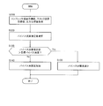
- FIG. 11 is a flowchart illustrating opening and closing of the bypass valve according to the first embodiment.
- FIG. 12 is a block diagram showing an example of a functional configuration for calculating a target value of the air flow rate to be supplied to the fuel cell and a target value of the air flow rate to be discharged from the compressor in the second embodiment.
- FIG. 13 is a map showing the relationship between the compressor required generated power and the stack required compressor flow rate according to the compressor discharge temperature.
- the fuel cell system 100 is a power recovery mechanism having a fuel cell stack 10, a cathode supply / discharge mechanism 12, an anode supply mechanism 14, a heat supply mechanism 15, a compressor 50 and a turbine 52. Compressor power supply mechanism 16, stack cooling mechanism 17, and controller 20.
- the fuel cell stack 10 is a stacked battery in which a plurality of fuel cells are stacked.
- the fuel cell stack 10 receives the supply of the anode gas (hydrogen) from the anode supply mechanism 14 and the supply of the cathode gas (air) from the cathode supply / exhaust mechanism 12 to generate electric power necessary for traveling of the vehicle.
- This generated electric power is used by various auxiliary machines such as the compressor 50 used when operating the fuel cell system 100 and a wheel driving motor (not shown).
- an impedance measuring device 11 Connected to the positive electrode terminal and the negative electrode terminal of the fuel cell stack 10 is an impedance measuring device 11 that measures impedance correlated with the wet state of the electrolyte membrane formed in the fuel cell stack 10.
- the impedance measuring device 11 supplies an alternating current to the positive terminal of the fuel cell stack 10 and detects an alternating current component of the voltage generated at the positive terminal and the negative terminal of the fuel cell stack 10.
- the impedance measuring device 11 calculates the AC resistance of the fuel cell stack 10, that is, HFR (High (frequency Resistance), based on the supplied AC current and the AC component of the detected voltage.
- the impedance measuring device 11 inputs the calculated HFR to the controller 20 as an HFR measurement value.
- the impedance measuring device 11 may measure the output voltage or output current of the fuel cell stack 10.
- the cathode supply / discharge mechanism 12 includes a cathode gas supply passage 22 and a cathode exhaust gas passage 24.
- the cathode gas supply passage 22 is a passage through which air supplied to the fuel cell stack 10 flows. One end of the cathode gas supply passage 22 is connected to the gas filter 23, and the other end is connected to the fuel cell stack 10.
- the cathode gas supply passage 22 is provided with an air flow sensor 26, a compressor discharge temperature sensor 27, an after cooler 28, a stack supply air temperature sensor 29, and an air pressure sensor 30 in this order from the upstream. .
- the air flow sensor 26 is provided at the intake inlet of the compressor 50 of the compressor power supply mechanism 16 in the cathode gas supply passage 22.
- the air flow sensor 26 detects the flow rate of air taken into the compressor 50 (hereinafter also referred to as “compressor flow rate”).
- compressor flow rate detection value the detection value of the air flow sensor 26 is also referred to as “compressor flow rate detection value”.
- the compressor flow rate detection value detected by the air flow sensor 26 is input to the controller 20.
- the compressor discharge temperature sensor 27 detects the air temperature (hereinafter also referred to as “compressor discharge temperature”) discharged from the compressor 50 and upstream from the aftercooler 28.
- a bypass passage 33 having a bypass valve 32 is connected between the air flow sensor 26 and the compressor discharge temperature sensor 27.
- the bypass passage 33 is a passage connecting the cathode gas supply passage 22 and the cathode exhaust gas passage 24. That is, the bypass passage 33 is a passage that bypasses the aftercooler 28 and the fuel cell stack 10 from the upstream side of the aftercooler 28 and supplies cathode gas to a catalytic combustor 36 described later.
- the aftercooler 28 cools the air discharged from the compressor 50 and sent to the fuel cell stack 10.
- the aftercooler 28 is configured as a water-cooled heat exchanger, and is connected to the stack cooling mechanism 17. That is, heat exchange is performed between the cooling water used for cooling the fuel cell stack 10 and the air to be supplied to the fuel cell stack 10 by the aftercooler 28.
- the stack supply air temperature sensor 29 detects the temperature of the cathode gas cooled by the aftercooler 28 and supplied to the fuel cell stack 10 (hereinafter also referred to as “stack supply air temperature”).
- the air pressure sensor 30 detects the pressure in the cathode gas supply passage 22, that is, the pressure of air supplied to the fuel cell stack 10 (hereinafter also referred to as “air pressure”).
- the detected air pressure value detected by the air pressure sensor 30 is input to the controller 20.
- the bypass valve 32 is a pressure regulating valve that adjusts the flow rate of air supplied to the cathode exhaust gas passage 24 by bypassing the fuel cell stack 10 and is controlled to be opened and closed by the controller 20. That is, the bypass valve 32 is a valve that adjusts the flow rate of air supplied from the compressor 50 to the cathode exhaust gas passage 24 by bypassing the fuel cell stack 10 via the bypass passage 33.
- the bypass passage 33 communicates with the upstream of the catalytic combustor 36 in the cathode exhaust gas passage 24 as described above. Accordingly, the oxygen concentration of the cathode exhaust gas supplied to the catalytic combustor 36 can be improved by supplying the air in the cathode gas supply passage 22 to the cathode exhaust gas passage 24 by the bypass passage 33.
- the cathode exhaust gas passage 24 has one end connected to the cathode outlet of the fuel cell stack 10 and the other end connected to the turbine 52.
- the cathode exhaust gas passage 24 is provided with a heat supply mechanism 15.
- the heat supply mechanism 15 has the above-described catalyst combustor 36 and a turbine inlet temperature sensor 38.
- the catalytic combustor 36 and the turbine inlet temperature sensor 38 are provided in the cathode exhaust gas passage 24 in this order from the fuel cell stack 10 to the turbine 52.
- the catalytic combustor 36 catalytically burns a mixed gas obtained by mixing anode gas and cathode gas with a mixer (not shown) by catalytic action of platinum or the like.
- the catalytic combustor 36 is supplied with anode gas from the anode supply mechanism 14 via the combustion anode gas supply passage 64, and from the fuel cell stack 10 via the cathode exhaust gas passage 24 to the cathode exhaust gas and bypass passage 33. Air is supplied from.
- the cathode gas supplied to the catalytic combustor 36 includes air supplied via the bypass passage 33 and cathode exhaust gas discharged from the fuel cell stack 10.
- the use of the catalytic combustor 36 as a combustor causes generation of nitrogen compounds (Nox) as compared with the case of using a diffusion combustion type combustor or a lean premixed combustion type combustor. It is suppressed.
- a combustor other than a catalytic combustor such as a diffusion combustion type combustor or a lean premixed combustion type combustor may be used.
- the turbine inlet temperature sensor 38 is a temperature of the post-combustion gas remaining after combustion by the catalytic combustor 36, that is, a temperature of the post-combustion gas supplied to the turbine 52 of the compressor power supply mechanism 16 (hereinafter referred to as “turbine inlet temperature”). Also described).
- the detected value of the turbine inlet temperature detected by the turbine inlet temperature sensor 38 is input to the controller 20.
- the anode supply mechanism 14 in the present embodiment includes a high-pressure tank 60, a stack anode gas supply passage 62, and a combustion anode gas supply passage 64.
- the high-pressure tank 60 is a gas storage container that stores hydrogen, which is the anode gas supplied to the fuel cell stack 10, while maintaining a high-pressure state.
- the stack anode gas supply passage 62 is a passage for supplying hydrogen discharged from the high-pressure tank 60 to the fuel cell stack 10.
- One end of the stack anode gas supply passage 62 is connected to the high-pressure tank 60, and the other end is connected to the fuel cell stack 10.
- the stack anode gas supply passage 62 is provided with an anode gas supply valve 66 and a hydrogen pressure detection sensor 67.
- the anode gas supply valve 66 is a pressure regulating valve that arbitrarily adjusts the amount of hydrogen supplied to the fuel cell stack 10.
- the hydrogen pressure detection sensor 67 detects the pressure of hydrogen supplied to the fuel cell stack 10 (hereinafter also referred to as “hydrogen pressure”).
- the detected hydrogen pressure value detected by the hydrogen pressure detection sensor 67 is input to the controller 20.
- combustion anode gas supply passage 64 is a passage for supplying a part of hydrogen discharged from the high-pressure tank 60 to the catalytic combustor 36.
- One end of the combustion anode gas supply passage 64 is branched to communicate with the stack anode gas supply passage 62, and the other end is connected to the catalytic combustor 36.
- the combustion anode gas supply passage 64 is provided with a combustor hydrogen supply valve 68 for arbitrarily adjusting the amount of hydrogen supplied to the catalyst combustor 36.
- the combustor hydrogen supply valve 68 is a pressure regulating valve that appropriately adjusts the amount of hydrogen supplied to the catalytic combustor 36 by adjusting its opening degree continuously or stepwise.
- the anode exhaust gas from the fuel cell stack 10 can be processed by, for example, a circulation type or non-circulation type anode exhaust mechanism (not shown).
- the compressor power supply mechanism 16 includes a compressor 50, a turbine 52, and a compressor drive motor 54 as an electric motor.
- the compressor 50 is connected to the compressor drive motor 54 and the turbine 52 via a rotary drive shaft 57.
- the compressor 50 is configured to be rotationally driven to suck outside air and to supply the cathode gas to the fuel cell stack 10 via the cathode gas supply passage 22. Note that the compressor 50 can be driven by either one or both of the power of the compressor drive motor 54 and the turbine 52.
- the turbine 52 is rotationally driven by the post-combustion gas supplied from the catalytic combustor 36.
- the turbine 52 outputs this rotational driving force to the compressor 50 via the rotational driving shaft 57 and the compressor driving motor 54. That is, the compressor 50 can be driven by the recovery power from the turbine 52. Further, the post-combustion gas after being used for driving the turbine 52 is discharged through the turbine exhaust passage 53.
- turbine gas inflow rate the supply flow rate of the post-combustion gas flowing into the turbine 52
- Turbine inlet temperature Temperature
- pressure can be increased to suitably power the compressor 50.
- the power recovered by the turbine 52 may be used not only in the rotational driving force of the compressor 50 but also in any other power request mechanism in the fuel cell system 100.
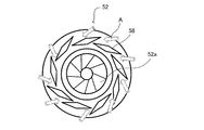
- the turbine 52 is provided with a nozzle vane 58 that adjusts the pressure of the gas after combustion supplied to the turbine 52.
- FIG. 2A and 2B are diagrams showing a schematic structure of the nozzle vane 58 provided in the turbine 52.
- FIG. 2A shows a state where the nozzle vane 58 is opened
- FIG. 2B shows a state where the nozzle vane 58 is closed.
- the flow direction of the inflow after-combustion gas is typically shown by the arrow A.
- the compressor drive motor 54 is connected to the compressor 50 on one side of the rotation drive shaft 57 and is connected to the turbine 52 on the other side of the rotation drive shaft 57.
- the compressor drive motor 54 generates power by being driven by rotation by an external force and a function (power running mode) as an electric motor that rotates by receiving power supplied from a battery (not shown), the fuel cell stack 10, the turbine 52, and the like. It has a function (regeneration mode) as a generator for supplying power to the battery or the fuel cell stack 10.
- the compressor drive motor 54 includes a motor case (not shown), a stator fixed to the inner peripheral surface of the motor case, a rotor disposed rotatably inside the stator, and a rotation drive shaft 57 provided on the rotor. Prepare.
- the compressor drive motor 54 is provided with a torque sensor 55 and a rotation speed sensor 56.
- the torque sensor 55 detects the torque of the compressor drive motor 54.
- the detected torque value of the compressor drive motor 54 detected by the torque sensor 55 is input to the controller 20.
- the rotation speed sensor 56 detects the rotation speed of the compressor drive motor 54.
- the compressor rotation speed detection value detected by the rotation speed sensor 56 is input to the controller 20.
- the stack cooling mechanism 17 includes a cooling water circulation channel 76 and a radiator 77 that heat-exchanges the cooling water flowing through the cooling water circulation channel 76 with outside air and cools the cooling water.
- the cooling water circulation path 76 is configured as an annular circulation path including a cooling water path of the fuel cell stack 10 (not shown).
- the cooling water circulation flow path 76 is provided with a cooling water circulation pump 78, which enables circulation of the cooling water.
- the cooling water circulating through the cooling water circulation passage 76 is supplied into the stack from the cooling water inlet 10 a of the fuel cell stack 10 and flows in the direction discharged from the cooling water outlet 10 b of the fuel cell stack 10.
- a radiator bypass three-way valve 80 is provided in the cooling water circulation passage 76 at a position upstream from the radiator 77.
- the radiator bypass three-way valve 80 adjusts the amount of cooling water supplied to the radiator 77. For example, when the temperature of the cooling water is relatively high, the radiator bypass three-way valve 80 is opened, and the cooling water is circulated to the radiator 77. On the other hand, when the temperature of the cooling water is relatively high, the radiator bypass three-way valve 80 is closed and the cooling water is allowed to flow through the bypass passage 80a so as to bypass the radiator 77.
- an inlet water temperature sensor 81 is provided in the vicinity of the cooling water inlet 10 a of the fuel cell stack 10 and an outlet water temperature sensor 82 is provided in the vicinity of the cooling water outlet 10 b of the fuel cell stack 10. Yes.
- the inlet water temperature sensor 81 detects the temperature of the cooling water flowing into the fuel cell stack 10.
- the outlet water temperature sensor 82 detects the temperature of the cooling water discharged from the fuel cell stack 10.
- the stack inlet water temperature detection value detected by the inlet water temperature sensor 81 and the stack outlet water temperature detection value detected by the outlet water temperature sensor 82 are input to the controller 20.
- the aftercooler 28 is connected to the cooling water circulation passage 76.
- the cooling water in the cooling water circulation passage 76 can be heated by the heat of the high-temperature air discharged from the compressor 50, It can meet the heat demand.
- the aftercooler 28 cools the high-temperature air discharged from the compressor 50, so that the air is supplied to the fuel cell stack 10 at a temperature suitable for the operation of the fuel cell stack 10. The heat exchanged by the aftercooler 28 is carried to the radiator 77 via the cooling water, and is radiated to the outside of the system.
- the fuel cell system 100 configured as described above has a controller 20 that comprehensively controls the system.
- the controller 20 includes a microcomputer having a central processing unit (CPU), a read only memory (ROM), a random access memory (RAM), and an input / output interface (I / O interface).
- CPU central processing unit
- ROM read only memory
- RAM random access memory
- I / O interface input / output interface
- signals from various sensors of the fuel cell system 100 In addition to signals from various sensors of the fuel cell system 100, signals from various sensors that detect the operating state of the fuel cell system 100 such as the atmospheric pressure sensor 111 that detects atmospheric pressure are input to the controller 20.
- the controller 20 receives an output request signal related to output power required for the fuel cell system 100 according to the load by the load device 110 (hereinafter also simply referred to as “request output”).
- the load device 110 is configured by, for example, a wheel driving motor or a secondary battery.
- the detection signal indicating the amount of depression of an accelerator pedal detected by an accelerator pedal sensor (not shown) increases, the required power of the load device 110 increases. Therefore, an output request input to the controller 20 The signal level of the signal is increased.
- the controller 20 performs drive control of the various valves 32, 66, 68, 80 including the compressor drive motor 54, the nozzle vane 58, the cooling water circulation pump 78, and the bypass valve 32 using these input signals and the like. For example, the controller 20 calculates a target value of the compressor flow rate and air pressure and a target value of the hydrogen supply pressure to the fuel cell stack 10 based on the power generation request signal of the load device 110, and according to the calculation result, The torque (power) of the compressor drive motor 54, the opening degree of the nozzle vane 58, and the opening degree of the anode gas supply valve 66 are controlled.
- the controller 20 also acquires information related to the power consumption of the compressor drive motor 54 as part of the request output.
- FIG. 3 illustrates feedback (F / B) control for the opening of the combustor hydrogen supply valve 68, the opening of the nozzle vane 58, the torque of the compressor drive motor 54, and the opening of the bypass valve 32 according to the present embodiment. It is a control block diagram to do.
- the control block shown in FIG. 3 includes a film wetting F / B control block B100, an air pressure target value calculation block B101, an air flow rate target value calculation block B102, a turbine inlet temperature target value calculation block B103, and a combustor hydrogen amount. It has an F / B control block B104, an air system F / B control block B105, and a bypass air amount control block B106.
- the membrane wet F / B control block B100 controls the HFR value correlated with the wet state so that the wet state of the electrolyte membrane formed in the fuel cell stack 10 is appropriately maintained.
- the HFR target value and the HFR measurement value are input to the film wetting F / B control block B100.
- the HFR target value is determined in advance using a map or the like that defines the relationship between the generated power of the fuel cell stack 10 and the HFR target value.
- the measured HFR value is measured using an impedance measuring device 11 provided in the fuel cell stack 10.
- the membrane wetting F / B control block B100 determines the required air pressure (hereinafter referred to as “wet demand air pressure Ph_r”). And a required air flow rate (hereinafter also referred to as “wet required air flow rate Fh_r”). That is, the film wetting F / B control block B100 calculates the required wet air pressure Ph_r and the required wet air flow rate Fh_r based on the HFR target value.
- the film wetting F / B control block B100 outputs the required wet air pressure Ph_r to the air pressure target value calculation block B101, and outputs the required wet air flow rate Fh_r to the target air flow value calculation block B102.
- the air pressure target value calculation block B101 calculates an air pressure target value Pc_t that is a target value of air pressure to be supplied to the fuel cell stack 10 based on the current target value Is_t.
- the current target value Is_t is a target value of the current to be taken out from the fuel cell stack 10 that is determined based on the system required output and the recovered power by the turbine 52.
- the target air current value Is_t, the stack temperature detection value Ts_d, and the required wet air pressure Ph_r calculated by the film wetting F / B control block B100 are input to the air pressure target value calculation block B101.
- the stack temperature detection value Ts_d is, for example, a value obtained by averaging the detection values detected by the inlet water temperature sensor 81 and the outlet water temperature sensor 82. Any one of the detected values may be used.
- the air pressure target value calculation block B101 is an air pressure target that is a target value of air pressure to be supplied to the fuel cell stack 10 based on the above-described current target value Is_t, stack temperature detection value Ts_d, and required wet air pressure Ph_r.
- a value Pc_t is calculated and output to the air flow rate target value calculation block B102 and the turbine inlet temperature target value calculation block B103.
- FIG. 4 is a block diagram showing details of the calculation method of the air pressure target value Pc_t executed by the air pressure target value calculation block B101.
- the block shown in the figure includes a power generation required air pressure calculation block B200 and a max select block B201.
- the current target value Is_t and the stack temperature detection value Ts_d are input to the power generation request air pressure calculation block B200. Then, the power generation request air pressure calculation block B200 generates a power generation request air pressure that is an air pressure required for power generation of the fuel cell stack 10 from the current target value Is_t and the stack temperature detection value Ts_d based on a map stored in advance. Pg_r is calculated. Furthermore, the power generation request air pressure calculation block B200 outputs the power generation request air pressure Pg_r to the max select block B201.
- the power generation required air pressure Pg_r increases as the current target value Is_t increases, and the power generation required air pressure increases as the stack temperature detection value Ts_d increases. Pg_r increases.
- the power generation required air pressure Pg_r calculated in the power generation required air pressure calculation block B200 and the moisture required air pressure Ph_r calculated in the membrane wetting F / B control block B100 are input to the Max Select block B201.
- the maximum select block B201 sets the larger one of the power generation required air pressure Pg_r and the wet required air pressure Ph_r as the air pressure target value Pc_t to the air flow rate target value calculation block B102 and the turbine inlet temperature target value calculation block B103. Output.
- the air pressure required for controlling the power generation state of the fuel cell stack 10 (power generation required air pressure Pg_r) and the air pressure required for operating the wet state of the electrolyte membrane.
- the maximum value is set as the air pressure target value Pc_t.
- the air flow rate target value calculation block B102 calculates the compressor flow rate target value Fco_t and the stack flow rate target value Fs_t.
- the stack flow rate target value Fs_t corresponds to the stack flow rate required for the electrode reaction in the cathode electrode of the fuel cell stack 10 when the fuel cell stack 10 generates target power. That is, the stack flow rate target value Fs_t corresponds to the stack flow rate required for setting the output current to the current target value Is_t when generating the target power.
- the air flow rate target value calculation block B102 includes an air pressure target value Pc_t, a current target value Is_t, a stack temperature detection value Ts_d, a wet required air flow rate Fh_r, hydrogen calculated by the air pressure target value calculation block B101.
- the pressure detection value Pan_d and the atmospheric pressure detection value Pai_d are input.
- the air flow rate target value calculation block B102 is based on these air pressure target value Pc_t, current target value Is_t, stack temperature detection value Ts_d, wet demand air flow rate Fh_r, hydrogen pressure detection value Pan_d, and atmospheric pressure detection value Pai_d.
- a flow rate target value Fco_t and a stack flow rate target value Fs_t are calculated.
- FIG. 5 is a block diagram showing details of a method of calculating the stack flow rate target value Fs_t and the compressor flow rate target value Fco_t executed by the air flow rate target value calculation block B102.
- the blocks shown in this figure are a power generation required air flow rate calculation block B300, a max select block B301, a pressure ratio target value calculation block B302, a stack required compressor flow rate calculation block B303, a dilution required flow rate calculation block B304, and a max select. Block B305.
- the current target value Is_t is input to the power generation required air flow rate calculation block B300.
- the power generation request air flow rate calculation block B300 calculates a power generation request air flow rate Fg_r that is an air flow rate required for power generation in the fuel cell stack 10 from the current target value Is_t based on a map stored in advance.
- the power generation request stack flow rate Fs_gr increases as the current target value Is_t increases. Furthermore, the power generation request air flow rate calculation block B300 outputs the power generation request air flow rate Fg_r to the max select block B301.
- the power generation required air flow rate Fg_r calculated by the power generation required air flow rate calculation block B300 and the moisture required air flow rate Fh_r are input to the Max Select block B301. Then, the Max select block B301 outputs the larger one of the power generation required air flow rate Fg_r and the wet required air flow rate Fh_r as the stack flow rate target value Fs_t. As a result, the stack flow rate target value Fs_t takes into consideration both the air flow rate based on the power generation request and the air flow rate based on the wet request.
- the air pressure target value Pc_t and the atmospheric pressure detection value Pai_d are input to the pressure ratio target value calculation block B302. Then, the pressure ratio target value calculation block B302 obtains the pressure ratio target value Pc_t / Pai_d by dividing the air pressure target value Pc_t by the atmospheric pressure detection value Pai_d, and outputs it to the stack required compressor flow rate calculation block B303.
- the required power Wco to the compressor motor and the pressure ratio target value Pc_t / Pai_d are input to the stack required compressor flow rate calculation block B303.
- the required power Wco to the compressor motor is defined as a value obtained by subtracting the power that can be output from the fuel cell stack 10 (hereinafter also simply referred to as “power that can be output”) from the required output.
- the power that can be output from the fuel cell stack 10 is determined according to the size of the fuel cell stack 10, the traveling state of the vehicle on which the fuel cell stack 10 is mounted, and the like.
- the required power Wco to the compressor motor is a positive value.
- the required power Wco to the compressor motor being a positive value means that the generated power of the fuel cell stack 10 with respect to the required output is insufficient. Therefore, in this embodiment, in this case, the power shortage is compensated by the regenerative power of the compressor drive motor 54 based on the recovered power of the turbine 52.
- the required power Wco to the compressor motor becomes a negative value. This is because the power generated by the fuel cell stack 10 is sufficient for the required output, and the compressor drive motor 54 is intended to operate in the powering mode.
- the pressure ratio target value Pc_t / Pai_d is set larger as the required power Wco to the compressor motor increases. That is, since the increase / decrease in the pressure ratio target value Pc_t / Pai_d is linked to the increase / decrease in the required power Wco to the compressor motor, if the magnitude of the pressure ratio target value Pc_t / Pai_d is seen, the required power Wco to the compressor motor is small or large. Can also be detected.
- the stack required compressor flow rate calculation block B303 calculates the stack required compressor flow rate Fco_sr from a predetermined map based on the input required power Wco to the compressor motor and the pressure ratio target value Pc_t / Pai_d.
- the stack required compressor flow rate Fco_sr is a candidate value for the compressor flow rate determined depending on the magnitude between the required output and the output power, that is, whether or not the generated power of the fuel cell stack 10 is insufficient. .
- FIG. 6 is a map showing the relationship between the required power Wco to the compressor motor according to the pressure ratio target value and the stack required compressor flow rate.
- the required power Wco to the compressor motor when the required power Wco to the compressor motor is a negative value (when the generated power of the fuel cell stack 10 is not insufficient), the required power Wco to the compressor motor becomes the predetermined value Wco1. Until it reaches, the stack required compressor flow rate Fco_sr is increased to a predetermined value Fco_sr1 regardless of the value of the pressure ratio target value Pc_t / Pai_d.
- the predetermined value Fco_sr1 is a value corresponding to the stack flow rate determined according to the required generated power of the fuel cell stack 10.
- the compressor drive motor 54 is operated in the power running mode, so there is no need to set the compressor flow rate exceeding the flow rate based on the required generated power of the fuel cell stack 10. Then, the compressor flow rate corresponding to the stack flow rate determined according to the required generated power of the fuel cell stack 10 is set.
- the stack required compressor flow rate Fco_sr is set according to the pressure ratio target value Pc_t / Pai_d. Is set.
- the stack required compressor flow rate Fco_sr is not increased regardless of the required power Wco to the compressor motor.
- the reason why the stack demand compressor flow rate Fco_sr is not increased beyond the predetermined value Fco_sr1 at low pressure in this way is that the pressure loss of the cathode system is large and the recovery power by the turbine 52 is low at low pressure, so the compressor flow rate is increased. This is because even if the turbine gas inflow rate is increased, a significant improvement in the recovery power by the turbine 52 cannot be expected.
- the stack request compressor The flow rate Fco_sr is increased from a predetermined value Fco_sr1 based on the required generated power of the fuel cell stack 10 to a predetermined value Fco_sr2.
- the reason why the stack required compressor flow rate Fco_sr is increased from the predetermined value Fco_sr1 based on the required power generation power of the fuel cell stack 10 at the intermediate pressure is that This is to increase the turbine gas inflow rate so as to obtain.
- the cathode system pressure loss is still large, and even if the turbine gas inflow rate is increased greatly, it is not possible to increase the recovery power beyond a certain level.
- the stack required compressor flow rate Fco_sr is increased to a predetermined value Fco_sr2.
- the degree of opening of the bypass valve 32 is increased so that the cathode gas exceeding the flow rate required by the fuel cell stack 10 is supplied to the aftercooler. Do not flush to 28. This point will be described later in detail.
- the stack required compressor flow rate Fco_sr is set to the predetermined value Fco_sr1 after the required power Wco to the compressor motor reaches the predetermined value Wco3. Increase from.
- the stack required compressor flow rate Fco_sr is increased from the predetermined value Fco_sr1 based on the required generated power of the fuel cell stack 10 so as to obtain regenerative power from the compressor drive motor 54 even at high pressure.
- the cathode system pressure loss is small, so that the turbine gas inflow rate can be greatly increased to increase the recovery power by the turbine 52 to a certain level or more.
- the opening degree of the bypass valve 32 is increased as the stack required compressor flow rate Fco_sr increases, so that the cathode gas exceeding the flow rate required by the fuel cell stack 10 does not flow to the aftercooler 28.
- the stack demand compressor flow rate calculation block B303 outputs the stack demand compressor flow rate Fco_sr calculated by the stack demand compressor flow rate calculation block B303 to the max select block B305.
- the stack temperature detection value Ts_d and the hydrogen pressure detection value Pan_d detected by the hydrogen pressure detection sensor 67 are input to the dilution request flow rate calculation block B304. Then, the dilution request flow rate calculation block B304 calculates a dilution request compressor flow rate Fco_dr that is an air flow rate required for diluting the anode exhaust gas discharged from the fuel cell stack 10 according to a predetermined map. Output to block B305.
- the dilution request compressor flow rate Fco_dr increases as the hydrogen pressure detection value Pan_d increases.
- the dilution request compressor flow rate Fco_dr decreases as the stack temperature detection value Ts_d increases. This is because when the stack temperature detection value Ts_d is high, the anode exhaust gas temperature is high, and the pressure loss of the anode exhaust gas discharge flow path becomes high and the flow rate decreases, so that it is necessary to perform correction to reduce the amount of air used for dilution. is there.
- the dilution request flow rate calculation block B304 outputs the dilution request compressor flow rate Fco_dr to the max select block B305.
- the Max select block B305 the stack request compressor flow rate Fco_sr output from the stack request compressor flow rate calculation block B303 and the dilution request compressor flow rate Fco_dr calculated in the dilution request flow rate calculation block B304 are input. Then, the Max select block B305 outputs the larger one of the stack required compressor flow rate Fco_sr and the dilution required compressor flow rate Fco_dr as the compressor flow rate target value Fco_t to each of the blocks B103, B105, and B106.
- the compressor flow rate target value Fco_t is determined in consideration of the required generated power of the fuel cell stack 10 and the anode exhaust gas dilution request.
- the compressor flow rate target value Fco_t may be determined in consideration of a surge avoidance request for avoiding a surge of the compressor 50.
- the turbine inlet temperature target value calculation block B103 is based on the flow rate and pressure of the cathode gas supplied to the fuel cell stack 10, and the temperature of the post-combustion gas discharged from the catalytic combustor 36 to the turbine 52, That is, the turbine inlet temperature is controlled.
- the turbine inlet temperature target value calculation block B103 is calculated by the atmospheric pressure detection value Pai_d, the air pressure target value Pc_t calculated by the air pressure target value calculation block B101, and the air flow rate target value calculation block B102.
- the compressed compressor flow rate target value Fco_t is input.
- the turbine inlet temperature target value calculation block B103 is based on the atmospheric pressure detected value Pai_d, the air pressure target value Pc_t, and the compressor flow rate target value Fco_t. Also referred to as “turbine inlet temperature target value Tt_t”).
- FIG. 7 is a block diagram showing details of a method for calculating the turbine inlet temperature target value Tt_t executed by the turbine inlet temperature target value calculation block B103.
- the block shown in this drawing has a pressure ratio target value calculation block B400 and a turbine inlet temperature target value setting block B401.
- the air pressure target value Pc_t and the atmospheric pressure detection value Pai_d are input to the pressure ratio target value calculation block B400. Then, the pressure ratio target value calculation block B400 obtains the pressure ratio target value Pc_t / Pai_d by dividing the air pressure target value Pc_t by the atmospheric pressure detection value Pai_d, and outputs it to the turbine inlet temperature target value setting block B401.
- the compressor inlet flow target value Fco_t and the pressure ratio target value Pc_t / Pai_d calculated by the pressure ratio target value calculation block B400 are input to the turbine inlet temperature target value setting block B401. Then, the turbine inlet temperature target value setting block B401 calculates a turbine inlet temperature target value Tt_t from the compressor flow rate target value Fco_t and the pressure ratio target value Pc_t / Pai_d based on a previously stored map.
- FIG. 8 is a diagram showing a map for determining the turbine inlet temperature target value.
- the turbine inlet temperature target value Tt_t is a pressure between a predetermined lower limit value Tt_tmin of the turbine inlet temperature and an allowable upper limit temperature Tt_tmax of the turbine inlet temperature determined in consideration of the heat resistant temperature of the parts. It fluctuates according to the ratio target value Pc_t / Pai_d and the compressor flow rate target value Fco_t.
- the pressure ratio target value Pc_t / Pai_d when the pressure ratio target value Pc_t / Pai_d is set to the largest value, when the pressure ratio target value Pc_t / Pai_d is set to an intermediate value, the pressure ratio target value Pc_t / Pai_d Is maintained at the lowest value, the turbine inlet temperature target value Tt_t is maintained at the lower limit value Tt_tmin until the compressor flow rate target value Fco_t reaches predetermined values f1, f2, and f3 (f1 ⁇ f2 ⁇ f3), respectively. And then increase.
- the reason why the turbine inlet temperature target value Tt_t starts to increase with a smaller compressor flow rate target value Fco_t as the pressure is higher is that the higher the pressure is, the more demanded the fuel cell stack 10 is for the same compressor flow rate target value Fco_t. This is because the generated power is large, and it is necessary to increase the recovered power from the turbine 52 by increasing the turbine inlet temperature.
- the turbine inlet temperature target value Tt_t is set to the allowable upper limit temperature Tt_tmax. This is because when the compressor flow rate target value Fco_t becomes larger than a certain value, the required output is large and the required power Wco to the compressor motor is large. Therefore, in order to increase the recovered power obtained by the turbine 52, the turbine This is to increase the inlet temperature rapidly. On the other hand, from the viewpoint of the heat-resistant temperature of the parts, the turbine inlet temperature is not increased beyond the allowable upper limit temperature Tt_tmax.
- the turbine inlet temperature detection value Tt_d and the turbine inlet temperature target value Tt_t calculated by the turbine inlet temperature target value calculation block B103 are input to the combustor hydrogen amount F / B control block B104.
- the combustor hydrogen amount F / B control block B104 feedback-controls the opening degree of the combustor hydrogen supply valve 68 so that the turbine inlet temperature detection value Tt_d approaches the turbine inlet temperature target value Tt_t.
- the opening degree of the combustor hydrogen supply valve 68 is increased as the required load on the fuel cell stack 10 and the required power from the turbine 52 increase. Specifically, when at least one of the stack flow rate target value Fs_t and the compressor flow rate target value Fco_t increases, the air supplied to the catalytic combustor 36 increases, so the opening of the combustor hydrogen supply valve 68 is increased. As a result, the amount of hydrogen supplied to the catalytic combustor 36 is increased in order to burn the air.
- Compressor flow rate detection value Fco_d and air pressure detection value Pc_d are input to the air system F / B control block B105 as detection values. Further, an air pressure target value Pc_t, a compressor flow rate target value Fco_t, and a stack flow rate target value Fs_t are input to the air system F / B control block B105 as target values.
- the air system F / B control block B105 feedback-controls the opening degree of the nozzle vane 58 and the torque of the compressor drive motor 54 based on the input detection values and target values. Specifically, the air system F / B control block B105 is used when the required load on the fuel cell stack 10 is high or when the required power of the turbine 52 is high, that is, at least the stack flow rate target value Fs_t and the compressor flow rate target value Fco_t. When either one increases, the opening degree of the nozzle vane 58 is increased.
- the torque (power) of the compressor drive motor 54 is controlled to increase as at least one of the air pressure target value Pc_t, the stack flow rate target value Fs_t, and the compressor flow rate target value Fco_t increases.
- bypass air amount control block B106 In the bypass air amount control block B106, an air pressure target value Pc_t, a compressor flow rate target value Fco_t, and a stack flow rate target value Fs_t are input.
- the bypass air amount control block B106 controls the opening degree of the bypass valve 32 based on these values.
- bypass air amount control block B106 controls the opening degree of the bypass valve 32 so that the air flow rate flowing through the bypass passage 33 becomes a difference between the compressor flow rate target value Fco_t and the stack flow rate target value Fs_t.
- compressor work Wc work used in the compressor 50
- turbine work Wt work that can be recovered from the turbine 52
- Fco is the compressor flow rate
- Cpc is the specific heat of the air supplied by the compressor 50
- Tc is the compressor discharge temperature
- Prc is the pressure ratio
- ⁇ c is the compressor efficiency.
- the specific heat Cpc of the air supplied by the compressor 50 and the compressor efficiency ⁇ c are fixed values determined in advance based on the properties of the compressor 50. Therefore, the compressor work Wc varies mainly according to the compressor flow rate Fco, the compressor discharge temperature Tc, and the pressure ratio Prc. Accordingly, based on the formula (1), the compressor work Wc increases when at least one of the compressor flow rate Fco, the compressor discharge temperature Tc, and the pressure ratio Prc increases.
- Wt Ft ⁇ Cpt ⁇ Tt ⁇ [1- (1 / Prt) ⁇ 0.286 ⁇ ⁇ ⁇ t (2) It is expressed.
- Ft is the flow rate of the burned gas flowing into the turbine 52 (hereinafter also referred to as “turbine flow rate”)
- Cpt is the specific heat of the burned gas flowing into the turbine 52
- Tt is the turbine inlet temperature
- Prt is the turbine
- the expansion ratio, ⁇ t means turbine efficiency.
- the specific heat Cpt of the post-combustion gas flowing into the turbine 52 can be determined in advance by regarding that the component of the post-combustion gas is substantially the same as that of air.
- the turbine efficiency ⁇ t can be determined in advance based on the properties of the turbine 52. Therefore, the turbine work Wt varies mainly according to the turbine inflow rate Ft, the turbine inlet temperature Tt, and the turbine expansion ratio Prt. Thereby, based on Formula (2), the turbine work Wt increases when at least one of the turbine inflow flow rate Ft and the turbine inlet temperature Tt increases.
- ⁇ Ps (k ⁇ Fs ⁇ Prc ⁇ Ts) / T0 (3) It is expressed.
- k is a pressure loss coefficient in the cathode flow path in the fuel cell stack 10
- Fs is a stack flow rate
- Ts is a stack temperature
- T0 is a standard state temperature ( ⁇ 273.15K).
- Prc in the equation (3) is obtained by the following equation using the turbine expansion ratio Prt described above.
- Prt Prc + ( ⁇ Ps / Patm) (4) Therefore, the pressure loss ⁇ Ps of the fuel cell stack 10 mainly increases when at least one of the stack flow rate Fs and the stack temperature Ts increases.
- Ft Fs ⁇ [0.79 + 0.21 ⁇ (1 + SRc) / SRc] + 1/2 ⁇ FH (5)
- SRc means the excess air ratio of the stack
- FH means the flow rate of hydrogen charged into the catalytic combustor 36.
- the hydrogen supply flow rate FH can be obtained from a predetermined map based on, for example, the hydrogen pressure detection value Pan_d by the hydrogen pressure detection sensor 67 and the opening degree of the combustor hydrogen supply valve 68.
- the turbine inlet temperature Tt is basically calculated from the gas flow rate supplied to the catalytic combustor 36, the specific heat, and the heat value determined by the hydrogen supply flow rate FH to the catalytic combustor 36.
- the turbine inlet temperature Tt is further adjusted so as not to exceed the allowable upper limit temperature Tt_tmax considering the heat resistant temperature of the parts.
- drive motor work Wm the work performed by the compressor drive motor 54 (hereinafter also referred to as “drive motor work Wm”) is basically given by the following equation (6).
- Wml Min (Wmlm, Wstmax-Wreq) (7)
- Min (a, b) means the smaller value of a and b (any may be used if they are the same).
- Wstmax is the power that can be output from the fuel cell stack 10.
- Wmlm is a limit value depending on the size of the compressor drive motor 54.
- the outputtable power Wstmax in the equation (7) is determined according to factors such as the running state of the vehicle on which the fuel cell stack 10 is mounted and the stack size. Therefore, for example, when the temperature is limited in a hot area, the outputtable power Wstmax is reduced.
- Wreq is a request output. That is, Wstmax-Wreq in the equation (7) corresponds to the above-described required power Wco for the compressor motor. Therefore, the work Wm of the compressor drive motor 54 is adjusted so as not to exceed the limit value Wml defined by the above equation (7).
- the turbine work Wt can cover the compressor work Wc, so that the power supplied from the fuel cell stack 10 or the battery to the compressor drive motor 54 can be reduced.
- the drive motor work Wm is a negative value, that is, when the compressor drive motor 54 is operated in the regeneration mode and no power is supplied from the compressor drive motor 54 to the compressor 50, the compressor work Wc is secured by the turbine work Wt. can do. Further, if the turbine work Wt is further increased, the power obtained by the regeneration of the compressor drive motor 54 is improved while securing the power of the compressor 50. Therefore, this power is used as the output power of the fuel cell stack 10 with respect to the required output. Can be used for shortages.
- FIG. 9 is a time chart showing changes in the state of the fuel cell system 100 according to the required output. Specifically, FIGS. 9 (a) to 9 (g) show the required stack flow rate, the required air pressure, the power required by the compressor 50 (hereinafter also referred to as “required compressor power”), hydrogen, and the required output, respectively.
- 6 is a time chart showing changes in fuel consumption, turbine inlet temperature Tt, compressor flow rate target value Fco_t, and bypass valve opening.
- the section I in which the requested output is Wreq1 or less, the section II in which the requested outputs are Wreq1 to Wreq2, the section III in which the requested outputs are Wreq2 to Wreq3, the section IV in which the requested outputs are Wreq3 to Wreq4, and the requested output is A change in the system state will be described for the section V that is Wreq4 to Wreq5.
- the section I it is a low load state in which power is not insufficient with respect to the required generated power of the fuel cell stack 10, and as shown in FIGS. 9A and 9B, the required stack flow rate and the required Air pressure value is relatively small. Further, as shown in FIG. 9C, the required compressor power increases as the required output increases, but it still reaches the limit value Wml (indicated by the broken line in the figure) of the output of the compressor drive motor 54. Absent.
- the compressor drive motor 54 can be operated in the power running mode because the compressor power can be supplied by the electric power from the fuel cell stack 10 and the battery without the recovery power from the turbine 52.
- the bypass valve 32 is basically fully closed as shown in FIG. In FIG. 9G, the bypass valve 32 is set to a constant opening in a region where the required output is close to zero. This is because, at an extremely low load, the dilution required compressor flow rate Fco_dr calculated in B304 of FIG. 5 becomes larger than the required stack flow rate, so that excess cathode gas with respect to the stack flow rate is passed through the bypass passage 33 to the cathode exhaust gas passage 24. It is intended to flow through.
- the auxiliary power such as the compressor drive motor 54 is reduced to reduce the fuel. It is necessary to compensate for the shortage of power generated by the battery stack 10. Therefore, the limit value Wml of the compressor drive motor 54 is lowered in order to reduce the power consumption of the compressor drive motor 54 (see FIG. 9C).
- the hydrogen fuel supply amount through the combustion anode gas supply passage 64 is increased in order to increase the recovery power by the turbine 52 in order to compensate for the power decrease of the compressor drive motor 54 accompanying the decrease in the limit value Wml. (See the shaded area in FIG. 9D).
- the turbine outlet temperature does not reach the upper limit temperature, and therefore it is possible to increase the turbine recovery power by increasing the temperature without increasing the bypass amount. Therefore, in this case, as shown in FIG. 9G, the bypass valve 32 is fully closed, and the required stack flow rate and the compressor flow rate target value Fco_t increase with an increase in the required output in a state of being substantially equal to each other (FIG. 9). (See (a) and FIG. 9 (f)).
- section IV is a section in which the requested outputs are Wreq3 to Wreq4. That is, it is a section where the load is higher than the sections I to III.
- the required output exceeds the power that can be output from the fuel cell stack 10 and the limit value Wml of the compressor drive motor 54 is zero, that is, the required output is not satisfied even if the power supply to the compressor drive motor 54 is zero. (Regeneration is required).
- control for increasing the turbine inflow rate Ft is not performed even at the stage of section IV.
- the bypass valve 32 is also fully closed. Therefore, the required stack flow rate and the compressor flow rate target value Fco_t increase with an increase in the required output in a substantially equal state (see FIGS. 9A and 9F).
- section V is a section in which the requested output is Wreq4 to Wreq5.
- the limit value Wml of the compressor drive motor 54 is further lowered. That is, the power generation amount of the fuel cell stack 10 is more insufficient than the required output.
- the turbine inlet temperature Tt reaches the allowable upper limit temperature Tt_tmax determined from the viewpoint of the heat-resistant temperature of the parts. Therefore, it is required to increase the recovery power by the turbine 52 while preventing the turbine inlet temperature Tt from increasing further.
- the compressor flow rate Fco is increased from the required stack flow rate.
- the opening degree of the bypass valve 32 is increased so as to flow excess air to the bypass passage 33 with respect to the required stack flow rate (see FIGS. 9F and 9G).
- bypass valve 32 by increasing the opening degree of the bypass valve 32, it is possible to supply surplus air with respect to the required stack flow rate to the catalytic combustor 36 via the bypass passage 33. This prevents an excessive flow rate from flowing to the aftercooler 28 (see FIG. 1) with respect to the required stack flow rate.
- the compressor flow rate Fco and the opening degree of the bypass valve 32 are increased to supply gas to the turbine 52.
- the recovery power from the turbine 52 can be improved while suppressing an increase in the turbine inlet temperature Tt.
- FIG. 10 is a diagram showing the relationship between the turbine inflow flow rate Ft, the recovered power by the turbine 52, and the compressor power according to the level of air pressure when the turbine inlet temperature Tt is the allowable upper limit temperature Tt_tmax.
- the recovery power by the turbine 52 is indicated by a solid line
- the required compressor power is indicated by a broken line.
- FIG. 10A shows a graph of turbine recovery power at low pressure (when the pressure ratio target value Pc_t / Pai_d is set to be the smallest), and FIG. 10B shows medium pressure (pressure ratio target value Pc_t / FIG. 10C shows a graph of turbine recovery power when Pai_d is set to an intermediate value, and FIG. 10C shows the turbine recovery power at high pressure (when the pressure ratio target value Pc_t / Pai_d is set to the largest value). The graph is shown.
- the pressure loss of the cathode system becomes large. Therefore, even if the compressor flow rate Fco is increased and the turbine inflow rate Ft is increased, it depends on the turbine 52. Recovery power cannot be increased significantly.
- the required compressor power increases as the compressor flow rate Fco increases, and when the compressor flow rate Fco reaches a predetermined value Fco1, the required compressor power starts to exceed the recovered power by the turbine 52. Therefore, at the time of low pressure, the compressor flow rate Fco is set to the same value as the stack flow rate Fs, and the bypass valve 32 is fully closed so that air is not supplied to the catalytic combustor 36 via the bypass passage 33.
- the amount of increase in the recovered power by the turbine 52 with respect to the increase in the turbine inflow flow rate Ft is larger than that at the low pressure. Therefore, even if the compressor flow rate Fco is increased to a certain level, the recovery power by the turbine 52 can be increased, and the state where the recovery power exceeds the required compressor power can be maintained. Therefore, at the intermediate pressure, the compressor flow rate Fco is adjusted to be larger than the stack flow rate Fs.
- the opening degree of the bypass valve 32 is increased and the air discharged from the compressor 50 is directly supplied to the catalytic combustor 36 via the bypass passage 33.
- the compressor flow rate Fco is increased as much as possible in order to increase the recovery power of the turbine 52. Then, excess air in which the compressor flow rate Fco exceeds the stack flow rate Fs is supplied to the catalytic combustor 36 via the bypass passage 33 by increasing the opening degree of the bypass valve 32 as in the case of the intermediate pressure. Thereby, the enlargement of the aftercooler 28 mentioned above, the overdrying of the fuel cell stack 10, etc. can be prevented.
- the upper limit of the amount of increase in the compressor flow rate Fco at high pressure is not particularly limited.
- the flow rate value obtained by subtracting the stack flow rate Fs from the compressor flow rate Fco is a flow rate that can pass through the bypass valve 32. It is preferable to limit the increase amount of the compressor flow rate Fco so as to be equal to or lower than the upper limit value.
- FIG. 11 is a flowchart illustrating opening and closing of the bypass valve 32 in the present embodiment.
- step S110 the controller 20 and various measuring devices obtain the compressor flow rate target value Fco_t, the stack flow rate target value Fs_t, and the air pressure target value Pc_t.
- step S120 the controller 20 calculates a bypass flow rate estimated value Fb_e from the stack flow rate target value Fs_t and the air pressure target value Pc_t using a previously designed map.
- the bypass flow rate estimated value Fb_e is calculated as a larger value as the stack flow rate target value Fs_t is larger and the air pressure target value Pc_t is larger.
- the target bypass flow rate Fb_t is calculated by subtracting the stack flow rate target value Fs_t from the compressor flow rate target value Fco_t.
- step S130 the controller 20 determines whether or not the bypass flow rate estimated value Fb_e is larger than the target bypass flow rate Fb_t. When it is determined that the estimated bypass flow rate Fb_e is equal to or less than the target bypass flow rate Fb_t, the process proceeds to step S140. In step S140, the controller 20 increases the opening degree of the bypass valve 32. On the other hand, if it is determined in step S130 that the bypass flow rate estimated value Fb_e is larger than the target bypass flow rate Fb_t, the process proceeds to step S150. In step S150, the controller 20 decreases the opening degree of the bypass valve 32.
- hydrogen is directly supplied from the high-pressure tank 60 to the catalytic combustor 36.
- the present invention is not limited to this.
- the anode exhaust gas flowing through the anode circulation passage in an anode circulation fuel cell system is used.
- a part may be supplied to the catalytic combustor 36.
- the stack current target value is used as a parameter representative of the load demand of the system, but the present invention is not limited to this. As long as the parameters are correlated, various other parameters such as a power target value and a voltage target value may be used.
- the fuel cell system 100 includes a fuel cell stack 10 that is a fuel cell that generates power by receiving supply of anode gas and cathode gas, a compressor 50 that supplies cathode gas to the fuel cell stack 10, and fuel.
- a turbine 52 that receives power from cathode exhaust gas discharged from the battery stack 10 to generate power
- a compressor 50 and a compressor drive motor 54 that is connected to the turbine 52 and that performs power running and regeneration, and the fuel cell stack 10
- a catalytic combustor 36 that is installed between the turbines 52 and mixes and burns the cathode gas and the anode gas, and an after-cooler that cools the cathode gas supplied from the compressor 50 to the fuel cell stack 10.
- the cooler 28 and the upstream of the aftercooler 28 Comprises a Takura 28 and the fuel cell stack 10 bypassing the catalytic combustor 36 bypass passage 33 for supplying the cathode gas to a bypass valve 32 provided in the bypass passage 33.
- surplus air for the power generation of the fuel cell stack 10 among the air discharged from the compressor 50 can be supplied to the catalytic combustor 36 via the bypass passage 33. Therefore, even if the flow rate of the compressor 50 is increased so as to improve the recovery power of the turbine 52, excess air can be directly supplied to the catalytic combustor 36 via the bypass valve 32.
- the recovered power of the turbine 52 provides power for the compressor 50 and power for regeneration of the compressor drive motor 54, and avoids flowing excess air to the aftercooler 28 for power generation of the fuel cell stack 10. can do.
- the power to the load of the fuel cell stack 10 is supplemented by the recovered power of the turbine 52 to reduce the amount of power that the fuel cell stack 10 should generate, thereby suppressing the maximum output performance of the fuel cell stack 10 and the fuel cell.
- the size of the stack 10 can be reduced.
- both the fuel cell stack 10 and the aftercooler 28 can be downsized, which contributes to downsizing of the fuel cell system 100 as a whole. Even when the system installation space is limited, such as when the vehicle is mounted on a vehicle, it can be handled.
- the fuel cell system 100 in which the compressor power supply mechanism 16 of the present embodiment is mounted can be suitably applied to the fuel cell stack 10 that operates at a relatively low temperature such as PEM.
- the controller 20 functions as a control unit that controls the bypass valve 32 based on a request output that is a load request of the system.
- the controller 20 functions as a control unit that controls the opening degree of the bypass valve 32 based on the pressure ratio target value that is the target value of the pressure ratio Prc of the compressor 50 with respect to the atmospheric pressure. To do.
- the opening degree of the bypass valve 32 is determined based on the pressure ratio target value that is the target value for the pressure ratio Prc correlated with the compressor discharge temperature, without directly detecting the compressor discharge temperature, It is possible to detect a high load state of the system (a state where the required output is relatively high) with high accuracy. Thereby, the opening degree of the bypass valve 32 can be increased more reliably in accordance with the high load state of the system, and as a result, the inflow of surplus air to the aftercooler 28 can be more reliably reduced. .
- the controller 20 requests the compressor flow rate Fco to be the flow rate required by the fuel cell stack 10 after the inlet temperature of the turbine 52 (turbine inlet temperature Tt) reaches the upper limit. It functions as a controller that increases the stack flow rate.
- the recovered power of the turbine 52 increases as the turbine inlet temperature Tt increases, but the turbine inlet temperature Tt cannot be higher than the allowable upper limit temperature Tt_tmax considering the heat resistance and the like of components. Therefore, when the turbine inlet temperature Tt reaches the allowable upper limit temperature Tt_tmax, the compressor flow rate Fco is set higher than the required stack flow rate to increase the turbine inflow rate Ft so that the turbine inlet temperature Tt does not increase.
- the recovery power can be further increased. In this case, by increasing the bypass valve 32, it is possible to accurately prevent this in a situation where surplus air flows into the aftercooler 28.
- the controller 20 can output a system request output (request output) determined based on a load connected to the fuel cell stack 10 and the fuel cell stack 10. It functions as a control unit that controls the compressor flow rate Fco based on the output power.
- the turbine inflow flow rate Ft can be suitably adjusted according to the required output and the output power, and the recovered power of the turbine 52 can be more suitably obtained.
- the heat exchanged by the aftercooler 28 can be transferred to the fuel cell stack 10 via the cooling water.
- the heat of the high-temperature air discharged from the compressor 50 can be supplied to the fuel cell stack 10. This contributes to improvement of the energy efficiency of the system.
- FIG. 12 is a block diagram showing a function for calculating the stack flow rate target value and the compressor flow rate target value Fco_t in the present embodiment.
- the compressor discharge temperature detection value detected by the compressor discharge temperature sensor 27 instead of inputting the pressure ratio target value Pc_t / Pai_d to the stack required compressor flow rate calculation block B303 as in the first embodiment. Enter Tc_d.
- the stack required compressor flow rate calculation block B303 calculates the stack required compressor flow rate Fco_sr according to a predetermined map based on the input required power Wco to the compressor motor and the compressor discharge temperature detection value Tc_d. calculate.
- FIG. 13 is a map showing the relationship between the required power Wco to the compressor motor and the stack required compressor flow rate Fco_sr according to the compressor discharge temperature.
- the required power Wco to the compressor motor when the required power Wco to the compressor motor is a negative value (when the generated power of the fuel cell stack 10 is not insufficient), the required power Wco to the compressor motor becomes the predetermined value Wco1.
- the stack required compressor flow rate Fco_sr is increased to a predetermined value Fco_sr1 regardless of the compressor discharge temperature detection value Tc_d.
- the predetermined value Fco_sr1 is a value corresponding to the stack flow rate determined according to the required generated power of the fuel cell stack 10. That is, in such a situation where the generated power is not insufficient, the compressor drive motor 54 is operated in the power running mode, so there is no need to set the compressor flow rate exceeding the flow rate based on the required generated power of the fuel cell stack 10. It is intended to set the compressor flow rate corresponding to the stack flow rate determined according to the required generated power of the fuel cell stack 10.
- the stack required compressor flow rate Fco_sr is set according to the compressor discharge temperature detection value Tc_d. Is done.
- the stack required compressor flow rate Fco_sr is set to the predetermined value Fco_sr1 without increasing regardless of the required power Wco to the compressor motor. Is done.
- the reason why the stack required compressor flow rate Fco_sr is not increased above the predetermined value Fco_sr1 at low temperatures is that the pressure loss of the cathode system is large at low temperatures and the recovery power by the turbine 52 is low. This is because even if the turbine gas inflow rate is increased, a significant improvement in the recovery power by the turbine 52 cannot be expected.
- the stack required compressor flow rate Fco_sr Is increased from a predetermined value Fco_sr1 based on the required generated power of the fuel cell stack 10 to a predetermined value Fco_sr2.
- the reason why the stack required compressor flow rate Fco_sr is increased from the predetermined value Fco_sr1 based on the required generated power of the fuel cell stack 10 at the middle temperature is to obtain regenerative power from the compressor drive motor 54 in order to eliminate the shortage of generated power.
- the turbine gas inflow rate is increased.
- the compressor flow rate is limited to the extent that the recovery power by the turbine 52 can be increased.
- the degree of opening of the bypass valve 32 is increased so that the cathode gas exceeding the flow rate required by the fuel cell stack 10 is supplied to the aftercooler. Do not flush to 28.
- the stack required compressor flow rate Fco_sr is changed from the predetermined value Fco_sr1 after the required power Wco to the compressor motor reaches the predetermined value Wco3. increase.
- the stack required compressor flow rate Fco_sr is increased from the predetermined value Fco_sr1 based on the required generated power of the fuel cell stack 10 so as to obtain regenerative power from the compressor drive motor 54 even at high temperatures.
- the pressure loss of the cathode system is small, so that the turbine gas inflow rate can be greatly increased, and the recovery power by the turbine 52 can be increased beyond a certain level.
- the opening degree of the bypass valve 32 is increased so that the cathode gas exceeding the flow rate required by the fuel cell stack 10 does not flow to the aftercooler 28. Like that.
- the opening / closing control of the bypass valve 32 in the present embodiment is the same as the opening degree control of the bypass valve 32 in the first embodiment described with reference to FIG.
- the fuel cell system 100 according to the second embodiment of the present invention described above has the following operational effects.
- the controller 20 functions as a control unit that controls the opening degree of the bypass valve 32 based on the compressor discharge temperature that is the temperature of the air discharged from the compressor 50.
- the opening degree of the bypass valve 32 can be controlled in accordance with the compressor discharge temperature that changes according to the load of the fuel cell stack 10, and the turbine inflow rate Ft can be adjusted.
- the increase timing of the opening degree of the bypass valve 32 can be reliably matched to the high load state of the system.
- the inflow of excess air to the aftercooler 28 can be more reliably reduced.
Landscapes
- Engineering & Computer Science (AREA)
- Chemical & Material Sciences (AREA)
- General Chemical & Material Sciences (AREA)
- Chemical Kinetics & Catalysis (AREA)
- Combustion & Propulsion (AREA)
- Sustainable Development (AREA)
- Sustainable Energy (AREA)
- Electrochemistry (AREA)
- Life Sciences & Earth Sciences (AREA)
- Manufacturing & Machinery (AREA)
- Mechanical Engineering (AREA)
- General Engineering & Computer Science (AREA)
- Physics & Mathematics (AREA)
- Fluid Mechanics (AREA)
- Fuel Cell (AREA)
Abstract
Description
(第1実施形態)
本発明の第1実施形態における燃料電池システム100は、燃料電池スタック10と、カソード給排機構12と、アノード供給機構14と、熱供給機構15と、コンプレッサ50及びタービン52を有する動力回収機構としてのコンプレッサ動力供給機構16と、スタック冷却機構17と、コントローラ20と、を有している。
Wc=Fco×Cpc×Tc×[(Prc)^0.286-1}/ηc・・・・(1)
と表される。ただし、Fcoはコンプレッサ流量、Cpcはコンプレッサ50により供給される空気の比熱、Tcはコンプレッサ吐出温度、Prcは圧力比、及びηcはコンプレッサ効率を意味する。本実施形態では、コンプレッサ50により供給される空気の比熱Cpcやコンプレッサ効率ηcは、コンプレッサ50の性質に基づいて予め定めた固定値を用いる。したがって、コンプレッサ仕事Wcは主として、コンプレッサ流量Fco、コンプレッサ吐出温度Tc、及び圧力比Prcに応じて変動することとなる。これにより、式(1)に基づけば、コンプレッサ仕事Wcは、コンプレッサ流量Fco、コンプレッサ吐出温度Tc、及び圧力比Prcの少なくとも何れかが増加すると増加する。
Wt=Ft×Cpt×Tt×[1-(1/Prt)^0.286}×ηt ・・・・(2)
と表される。ただし、Ftはタービン52へ流入する燃焼後ガスの流量(以下では、「タービン流入流量」とも記載する)、Cptはタービン52へ流入する燃焼後ガスの比熱、Ttはタービン入口温度、Prtはタービン膨張比、ηtはタービン効率を意味する。ここで、本実施形態では、タービン52へ流入する燃焼後ガスの比熱Cptについては、燃焼後ガスの成分が空気とほぼ同じであるとみなすことなどにより予め定めることができる。またタービン効率ηtは、タービン52の性質に基づいて予め定めることができる。したがって、タービン仕事Wtは主として、タービン流入流量Ft、タービン入口温度Tt、及びタービン膨張比Prtに応じて変動することとなる。これにより、式(2)に基づけば、タービン仕事Wtは、タービン流入流量Ft、及びタービン入口温度Ttの少なくとも何れかが増加すると増加する。
ΔPs=(k×Fs×Prc×Ts)/T0・・・・(3)
と表される。ただし、kは燃料電池スタック10内のカソード流路における圧力損失係数、Fsはスタック流量、Tsはスタック温度、及びT0は標準状態の温度(≒273.15K)を意味する。また、式(3)中のPrcは、既に述べたタービン膨張比Prtを用いて以下の式により求められる。
したがって、燃料電池スタック10の圧力損失ΔPsは、主に、スタック流量Fs及びスタック温度Tsの少なくとも何れかが増加すると増加することとなる。
ただし、SRcはスタックの空気過剰率、FHは触媒燃焼器36に投入される水素流量を意味する。なお、水素供給流量FHは、例えば水素圧力検出センサ67による水素圧力検出値Pan_dと燃焼器水素供給弁68の開度等に基づいて、所定のマップにより求めることができる。
ただし、駆動モータ仕事Wmについては、コンプレッサ駆動モータ54のサイズによる制限と燃料電池スタック10の要求発電電力による制限を考慮する必要がある。したがって、駆動モータ仕事Wmは、以下の制限値Wmlに制限される。
ここで、Min(a,b)とは、aとbの内の小さい方の値(同一ならば何れでも良い)を意味する。式(7)中、Wstmaxは燃料電池スタック10の出力可能電力である。Wmlmは、コンプレッサ駆動モータ54のサイズによる制限値である。
(第2実施形態)
次に本発明の第2実施形態における燃料電池システムについて説明する。なお、第1実施形態と同様の要素には同一の符号を付し、その説明を省略する。
Claims (8)
- アノードガス及びカソードガスの供給を受けて発電する燃料電池と、
前記燃料電池に前記カソードガスを供給するコンプレッサと、
前記燃料電池から排出されるカソード排ガスの供給を受けて動力を生成するタービンと、
前記コンプレッサ及び前記タービンに連結され力行と回生を行う電動モータと、
前記燃料電池と前記タービンの間に設置され前記カソードガスとアノードガスとを混合して燃焼させる燃焼器と、
前記コンプレッサから前記燃料電池に供給される前記カソードガスを冷却する冷却器と、
前記冷却器の上流から前記冷却器と前記燃料電池をバイパスして前記燃焼器に前記カソードガスを供給するバイパス通路と、
前記バイパス通路に設けられたバイパス弁と、
を備える燃料電池システム。 - 請求項1に記載の燃料電池システムであって、
システムの負荷要求に基づいて前記バイパス弁を制御する制御部を備えた燃料電池システム。 - 請求項2に記載の燃料電池システムであって、
前記制御部は、
前記コンプレッサから吐出される空気の温度に基づいて前記バイパス弁の開度を制御する燃料電池システム。 - 請求項2又は請求項3に記載の燃料電池システムであって、
前記制御部は、
大気圧に対する前記コンプレッサの圧力比の目標値に基づいて前記バイパス弁の開度を制御する燃料電池システム。 - 請求項2~請求項4の何れか1項に記載の燃料電池システムであって、
前記制御部は、
前記タービンの入口温度が許容上限温度に達した後に、前記コンプレッサの流量を前記燃料電池が要求する流量よりも増加させる燃料電池システム。 - 請求項2~請求項4の何れか1項に記載の燃料電池システムであって、
前記制御部は、
前記燃料電池に接続される負荷に基づき定められるシステム要求出力と、前記燃料電池が出力することが可能な出力可能電力と、に基づいて前記コンプレッサの流量を制御する燃料電池システム。 - 請求項1~請求項6の何れか1項に記載の燃料電池システムであって、
前記冷却器は、前記燃料電池と熱交換を行う燃料電池システム。 - アノードガス及びカソードガスの供給を受けて発電する燃料電池と、前記燃料電池に前記カソードガスを供給するコンプレッサと、前記燃料電池から排出されるカソード排ガスの供給を受けて動力を生成するタービンと、前記コンプレッサ及び前記タービンに連結され力行と回生を行う電動モータと、前記燃料電池と前記タービンの間に設置され前記カソードガスとアノードガスとを混合して燃焼させる燃焼器と、前記コンプレッサから前記燃料電池に供給される前記カソードガスを冷却する冷却器と、前記冷却器の上流から前記冷却器と前記燃料電池をバイパスして前記燃焼器に前記カソードガスを供給するバイパス通路と、前記バイパス通路に設けられたバイパス弁と、を備える燃料電池システムで実行される燃料電池システムの制御方法であって、
システムの負荷要求に基づいて前記バイパス弁を制御する燃料電池システムの制御方法。
Priority Applications (7)
| Application Number | Priority Date | Filing Date | Title |
|---|---|---|---|
| KR1020187028824A KR102025503B1 (ko) | 2016-03-22 | 2016-12-08 | 연료 전지 시스템 및 연료 전지 시스템의 제어 방법 |
| JP2018506766A JP6573022B2 (ja) | 2016-03-22 | 2016-12-08 | 燃料電池システム及び燃料電池システムの制御方法 |
| CA3018246A CA3018246C (en) | 2016-03-22 | 2016-12-08 | Fuel cell system and method for controlling fuel cell system |
| CN201680083935.8A CN108886153B (zh) | 2016-03-22 | 2016-12-08 | 燃料电池系统以及燃料电池系统的控制方法 |
| US16/086,867 US10930948B2 (en) | 2016-03-22 | 2016-12-08 | Fuel cell system and method for controlling fuel cell system including power recovery mechanism |
| KR1020197018222A KR102054636B1 (ko) | 2016-03-22 | 2016-12-08 | 연료 전지 시스템 및 연료 전지 시스템의 제어 방법 |
| EP16895522.7A EP3435461B1 (en) | 2016-03-22 | 2016-12-08 | Fuel cell system and method for controlling fuel cell system |
Applications Claiming Priority (2)
| Application Number | Priority Date | Filing Date | Title |
|---|---|---|---|
| JP2016056453 | 2016-03-22 | ||
| JP2016-056453 | 2016-03-22 |
Publications (1)
| Publication Number | Publication Date |
|---|---|
| WO2017163499A1 true WO2017163499A1 (ja) | 2017-09-28 |
Family
ID=59901093
Family Applications (1)
| Application Number | Title | Priority Date | Filing Date |
|---|---|---|---|
| PCT/JP2016/086635 WO2017163499A1 (ja) | 2016-03-22 | 2016-12-08 | 燃料電池システム及び燃料電池システムの制御方法 |
Country Status (7)
| Country | Link |
|---|---|
| US (1) | US10930948B2 (ja) |
| EP (1) | EP3435461B1 (ja) |
| JP (1) | JP6573022B2 (ja) |
| KR (2) | KR102054636B1 (ja) |
| CN (1) | CN108886153B (ja) |
| CA (1) | CA3018246C (ja) |
| WO (1) | WO2017163499A1 (ja) |
Cited By (4)
| Publication number | Priority date | Publication date | Assignee | Title |
|---|---|---|---|---|
| EP3474362A1 (en) * | 2017-10-20 | 2019-04-24 | Toyota Jidosha Kabushiki Kaisha | Fuel cell system and control method of fuel cell system |
| JP2019145488A (ja) * | 2017-11-28 | 2019-08-29 | トヨタ モーター エンジニアリング アンド マニュファクチャリング ノース アメリカ,インコーポレイテッド | 冷却システムdT/dtに基づく制御 |
| JP2021190266A (ja) * | 2020-05-28 | 2021-12-13 | トヨタ自動車株式会社 | 燃料電池システム |
| JP2021190238A (ja) * | 2020-05-27 | 2021-12-13 | トヨタ自動車株式会社 | 燃料電池システム |
Families Citing this family (11)
| Publication number | Priority date | Publication date | Assignee | Title |
|---|---|---|---|---|
| JP6766639B2 (ja) * | 2016-12-26 | 2020-10-14 | 株式会社デンソー | 燃料電池冷却システム |
| US10978723B2 (en) * | 2018-09-05 | 2021-04-13 | Honeywell International Inc. | Fuel cell secondary power and thermal management systems |
| JP7238805B2 (ja) * | 2020-01-16 | 2023-03-14 | トヨタ自動車株式会社 | 燃料電池システム |
| CN112201810B (zh) * | 2020-09-25 | 2024-05-28 | 上海华熵能源科技有限公司 | 一种稳压供气的氢燃料电池装置 |
| CN112421075A (zh) * | 2020-11-17 | 2021-02-26 | 一汽解放汽车有限公司 | 一种燃料电池发动机空气供给系统 |
| CN114754024A (zh) * | 2021-01-12 | 2022-07-15 | 海德韦尔(太仓)能源科技有限公司 | 一种压气机和包括压气机的空气压缩机以及燃料电池装置 |
| JP7213287B2 (ja) * | 2021-03-16 | 2023-01-26 | 本田技研工業株式会社 | 暖機システム |
| US20220367890A1 (en) * | 2021-05-17 | 2022-11-17 | General Electric Company | Control system for a fuel cell and engine combustor assembly |
| KR102536353B1 (ko) * | 2021-10-27 | 2023-05-26 | 두산에너빌리티 주식회사 | 복합 발전 시스템 및 복합 발전 시스템의 운영 방법 |
| WO2023249659A1 (en) * | 2022-06-23 | 2023-12-28 | Zeroavia Ltd | Thrust from hydrogen fuel cell waste |
| CN115295826B (zh) * | 2022-07-25 | 2023-04-18 | 上海杰宁新能源科技发展有限公司 | 一种燃料电池控制方法、系统、存储介质及智能终端 |
Citations (5)
| Publication number | Priority date | Publication date | Assignee | Title |
|---|---|---|---|---|
| JP2002270205A (ja) * | 2001-03-09 | 2002-09-20 | Meidensha Corp | 燃料電池システム、およびこのシステムを利用した動力装置並びに発電設備 |
| JP2004119239A (ja) | 2002-09-27 | 2004-04-15 | Mitsubishi Heavy Ind Ltd | 燃料電池−ガスタービン発電設備及び複合発電設備 |
| JP2007234311A (ja) * | 2006-02-28 | 2007-09-13 | Nissan Motor Co Ltd | 燃料電池システム |
| JP2010020924A (ja) * | 2008-07-08 | 2010-01-28 | Toyota Motor Corp | 燃料電池システム |
| JP2014165072A (ja) * | 2013-02-26 | 2014-09-08 | Mitsubishi Heavy Ind Ltd | 燃料電池発電システム、コンバインド発電システム、運転方法、及び制御装置 |
Family Cites Families (16)
| Publication number | Priority date | Publication date | Assignee | Title |
|---|---|---|---|---|
| US3976506A (en) * | 1975-02-12 | 1976-08-24 | United Technologies Corporation | Pressurized fuel cell power plant with air bypass |
| US4838020A (en) * | 1985-10-24 | 1989-06-13 | Mitsubishi Denki Kabushiki Kaisha | Turbocompressor system and method for controlling the same |
| JP3137147B2 (ja) * | 1992-08-28 | 2001-02-19 | 石川島播磨重工業株式会社 | 燃料電池設備用タービン・コンプレッサ装置の制御方法 |
| JPH11339831A (ja) | 1998-05-31 | 1999-12-10 | Aisin Seiki Co Ltd | 車両搭載用燃料電池システム |
| JP3832802B2 (ja) * | 2000-07-25 | 2006-10-11 | 本田技研工業株式会社 | 燃料電池システムおよびその制御方法 |
| US6896988B2 (en) * | 2003-09-11 | 2005-05-24 | Fuelcell Energy, Inc. | Enhanced high efficiency fuel cell/turbine power plant |
| JP4939362B2 (ja) | 2007-10-15 | 2012-05-23 | 三菱重工業株式会社 | 燃料電池−ガスタービン発電設備及び複合発電設備 |
| DE102008049689A1 (de) * | 2008-09-30 | 2010-04-01 | Daimler Ag | Luftversorgungseinrichtung für einen Brennstoffzellenstapel, Brennstoffzellensystem und Verfahren zum Betreiben einer Luftversorgungseinrichtung |
| JP5389090B2 (ja) * | 2011-03-31 | 2014-01-15 | 本田技研工業株式会社 | 燃料電池システム |
| US8962208B2 (en) * | 2012-10-25 | 2015-02-24 | GM Global Technology Operations LLC | Predictive cathode compressor speed control in a fuel cell power system |
| JP6109529B2 (ja) * | 2012-10-31 | 2017-04-05 | 三菱日立パワーシステムズ株式会社 | 発電システム |
| JP6116871B2 (ja) * | 2012-11-22 | 2017-04-19 | 三菱日立パワーシステムズ株式会社 | 発電システム及び発電システムの運転方法 |
| WO2014103589A1 (ja) * | 2012-12-28 | 2014-07-03 | 日産自動車株式会社 | 燃料電池システム及びその制御方法 |
| CN106575780B (zh) | 2014-07-24 | 2019-12-03 | 日产自动车株式会社 | 燃料电池系统 |
| JP6172115B2 (ja) * | 2014-10-29 | 2017-08-02 | トヨタ自動車株式会社 | 燃料電池システム及び燃料電池システムの制御方法 |
| CN105261771B (zh) * | 2015-10-20 | 2016-08-31 | 华中科技大学 | 一种固体氧化物燃料电池系统 |
-
2016
- 2016-12-08 CN CN201680083935.8A patent/CN108886153B/zh active Active
- 2016-12-08 CA CA3018246A patent/CA3018246C/en active Active
- 2016-12-08 JP JP2018506766A patent/JP6573022B2/ja active Active
- 2016-12-08 KR KR1020197018222A patent/KR102054636B1/ko active IP Right Grant
- 2016-12-08 WO PCT/JP2016/086635 patent/WO2017163499A1/ja active Application Filing
- 2016-12-08 KR KR1020187028824A patent/KR102025503B1/ko active IP Right Grant
- 2016-12-08 US US16/086,867 patent/US10930948B2/en active Active
- 2016-12-08 EP EP16895522.7A patent/EP3435461B1/en active Active
Patent Citations (5)
| Publication number | Priority date | Publication date | Assignee | Title |
|---|---|---|---|---|
| JP2002270205A (ja) * | 2001-03-09 | 2002-09-20 | Meidensha Corp | 燃料電池システム、およびこのシステムを利用した動力装置並びに発電設備 |
| JP2004119239A (ja) | 2002-09-27 | 2004-04-15 | Mitsubishi Heavy Ind Ltd | 燃料電池−ガスタービン発電設備及び複合発電設備 |
| JP2007234311A (ja) * | 2006-02-28 | 2007-09-13 | Nissan Motor Co Ltd | 燃料電池システム |
| JP2010020924A (ja) * | 2008-07-08 | 2010-01-28 | Toyota Motor Corp | 燃料電池システム |
| JP2014165072A (ja) * | 2013-02-26 | 2014-09-08 | Mitsubishi Heavy Ind Ltd | 燃料電池発電システム、コンバインド発電システム、運転方法、及び制御装置 |
Non-Patent Citations (1)
| Title |
|---|
| See also references of EP3435461A4 |
Cited By (13)
| Publication number | Priority date | Publication date | Assignee | Title |
|---|---|---|---|---|
| US10957926B2 (en) | 2017-10-20 | 2021-03-23 | Toyota Jidosha Kabushiki Kaisha | Fuel cell system and control method of fuel cell system |
| KR20190044516A (ko) * | 2017-10-20 | 2019-04-30 | 도요타지도샤가부시키가이샤 | 연료 전지 시스템 및 연료 전지 시스템의 제어 방법 |
| CN109698369A (zh) * | 2017-10-20 | 2019-04-30 | 丰田自动车株式会社 | 燃料电池系统和燃料电池系统的控制方法 |
| JP2019079606A (ja) * | 2017-10-20 | 2019-05-23 | トヨタ自動車株式会社 | 燃料電池システムおよび燃料電池システムの制御方法 |
| KR102139197B1 (ko) * | 2017-10-20 | 2020-07-29 | 도요타지도샤가부시키가이샤 | 연료 전지 시스템 및 연료 전지 시스템의 제어 방법 |
| EP3474362A1 (en) * | 2017-10-20 | 2019-04-24 | Toyota Jidosha Kabushiki Kaisha | Fuel cell system and control method of fuel cell system |
| CN109698369B (zh) * | 2017-10-20 | 2022-03-01 | 丰田自动车株式会社 | 燃料电池系统和燃料电池系统的控制方法 |
| JP2019145488A (ja) * | 2017-11-28 | 2019-08-29 | トヨタ モーター エンジニアリング アンド マニュファクチャリング ノース アメリカ,インコーポレイテッド | 冷却システムdT/dtに基づく制御 |
| JP7296203B2 (ja) | 2017-11-28 | 2023-06-22 | トヨタ モーター エンジニアリング アンド マニュファクチャリング ノース アメリカ,インコーポレイテッド | 冷却システムdT/dtに基づく制御 |
| JP2021190238A (ja) * | 2020-05-27 | 2021-12-13 | トヨタ自動車株式会社 | 燃料電池システム |
| JP7247958B2 (ja) | 2020-05-27 | 2023-03-29 | トヨタ自動車株式会社 | 燃料電池システム |
| JP2021190266A (ja) * | 2020-05-28 | 2021-12-13 | トヨタ自動車株式会社 | 燃料電池システム |
| JP7276251B2 (ja) | 2020-05-28 | 2023-05-18 | トヨタ自動車株式会社 | 燃料電池システム |
Also Published As
| Publication number | Publication date |
|---|---|
| KR102054636B1 (ko) | 2019-12-10 |
| KR20180119166A (ko) | 2018-11-01 |
| CA3018246C (en) | 2019-08-06 |
| US10930948B2 (en) | 2021-02-23 |
| US20190088962A1 (en) | 2019-03-21 |
| EP3435461A4 (en) | 2019-10-02 |
| KR102025503B1 (ko) | 2019-09-26 |
| EP3435461A1 (en) | 2019-01-30 |
| CA3018246A1 (en) | 2017-09-28 |
| KR20190076073A (ko) | 2019-07-01 |
| CN108886153A (zh) | 2018-11-23 |
| JP6573022B2 (ja) | 2019-09-11 |
| JPWO2017163499A1 (ja) | 2019-01-31 |
| EP3435461B1 (en) | 2023-06-28 |
| CN108886153B (zh) | 2019-11-29 |
Similar Documents
| Publication | Publication Date | Title |
|---|---|---|
| JP6573022B2 (ja) | 燃料電池システム及び燃料電池システムの制御方法 | |
| JP6206440B2 (ja) | 燃料電池システム | |
| US8173315B2 (en) | Fuel battery system, method for detecting gas leakage in such system, and mobile object | |
| JP4936126B2 (ja) | 燃料電池システム | |
| JP6187774B2 (ja) | 燃料電池システム及び燃料電池システムの運転制御方法 | |
| US10115989B2 (en) | Operation method of fuel cell system and fuel cell system | |
| EP3392946B1 (en) | Fuel cell system and control method for fuel cell system | |
| WO2017098782A1 (ja) | 燃料電池システム | |
| JP5092335B2 (ja) | 燃料電池システム及び燃料電池システム制御方法 | |
| JP2004265683A (ja) | 燃料電池発電制御システム | |
| JP4375208B2 (ja) | 燃料電池の出力制限装置 | |
| JP2016035870A (ja) | 燃料電池システム | |
| JP2014220156A (ja) | 燃料電池システムの制御装置 | |
| JP6790509B2 (ja) | 燃料電池システム及び燃料電池システムの制御方法 | |
| KR20190063313A (ko) | 오픈 캐소드 타입 연료전지의 팬 제어 장치 | |
| JP3873803B2 (ja) | 燃料電池制御システム | |
| JP5057086B2 (ja) | ポンプ駆動制御装置 | |
| JP2010146750A (ja) | 燃料電池システム | |
| JP6717085B2 (ja) | 燃料電池システム | |
| JP6665510B2 (ja) | 燃料電池システム及び燃料電池システムの制御方法 | |
| JP6790510B2 (ja) | 燃料電池システム及び燃料電池システムの制御方法 | |
| JP6729090B2 (ja) | 燃料電池システムおよびその制御方法 | |
| JP6394875B2 (ja) | 燃料電池システム |
Legal Events
| Date | Code | Title | Description |
|---|---|---|---|
| WWE | Wipo information: entry into national phase |
Ref document number: 2018506766 Country of ref document: JP |
|
| ENP | Entry into the national phase |
Ref document number: 3018246 Country of ref document: CA |
|
| NENP | Non-entry into the national phase |
Ref country code: DE |
|
| ENP | Entry into the national phase |
Ref document number: 20187028824 Country of ref document: KR Kind code of ref document: A |
|
| WWE | Wipo information: entry into national phase |
Ref document number: 2016895522 Country of ref document: EP |
|
| ENP | Entry into the national phase |
Ref document number: 2016895522 Country of ref document: EP Effective date: 20181022 |
|
| 121 | Ep: the epo has been informed by wipo that ep was designated in this application |
Ref document number: 16895522 Country of ref document: EP Kind code of ref document: A1 |