WO2017159819A1 - 薬品払出装置、薬品払出プログラム - Google Patents
薬品払出装置、薬品払出プログラム Download PDFInfo
- Publication number
- WO2017159819A1 WO2017159819A1 PCT/JP2017/010782 JP2017010782W WO2017159819A1 WO 2017159819 A1 WO2017159819 A1 WO 2017159819A1 JP 2017010782 W JP2017010782 W JP 2017010782W WO 2017159819 A1 WO2017159819 A1 WO 2017159819A1
- Authority
- WO
- WIPO (PCT)
- Prior art keywords
- medicine
- cassette
- information
- control unit
- unit
- Prior art date
- Legal status (The legal status is an assumption and is not a legal conclusion. Google has not performed a legal analysis and makes no representation as to the accuracy of the status listed.)
- Ceased
Links
Images







Classifications
-
- A—HUMAN NECESSITIES
- A61—MEDICAL OR VETERINARY SCIENCE; HYGIENE
- A61J—CONTAINERS SPECIALLY ADAPTED FOR MEDICAL OR PHARMACEUTICAL PURPOSES; DEVICES OR METHODS SPECIALLY ADAPTED FOR BRINGING PHARMACEUTICAL PRODUCTS INTO PARTICULAR PHYSICAL OR ADMINISTERING FORMS; DEVICES FOR ADMINISTERING FOOD OR MEDICINES ORALLY; BABY COMFORTERS; DEVICES FOR RECEIVING SPITTLE
- A61J3/00—Devices or methods specially adapted for bringing pharmaceutical products into particular physical or administering forms
-
- A—HUMAN NECESSITIES
- A61—MEDICAL OR VETERINARY SCIENCE; HYGIENE
- A61J—CONTAINERS SPECIALLY ADAPTED FOR MEDICAL OR PHARMACEUTICAL PURPOSES; DEVICES OR METHODS SPECIALLY ADAPTED FOR BRINGING PHARMACEUTICAL PRODUCTS INTO PARTICULAR PHYSICAL OR ADMINISTERING FORMS; DEVICES FOR ADMINISTERING FOOD OR MEDICINES ORALLY; BABY COMFORTERS; DEVICES FOR RECEIVING SPITTLE
- A61J7/00—Devices for administering medicines orally, e.g. spoons; Pill counting devices; Arrangements for time indication or reminder for taking medicine
- A61J7/0076—Medicament distribution means
-
- G—PHYSICS
- G16—INFORMATION AND COMMUNICATION TECHNOLOGY [ICT] SPECIALLY ADAPTED FOR SPECIFIC APPLICATION FIELDS
- G16H—HEALTHCARE INFORMATICS, i.e. INFORMATION AND COMMUNICATION TECHNOLOGY [ICT] SPECIALLY ADAPTED FOR THE HANDLING OR PROCESSING OF MEDICAL OR HEALTHCARE DATA
- G16H70/00—ICT specially adapted for the handling or processing of medical references
- G16H70/40—ICT specially adapted for the handling or processing of medical references relating to drugs, e.g. their side effects or intended usage
Definitions
- the medicine information is information that can identify the type of tablet (medicine), and is, for example, a medicine name, a medicine ID, a medicine code, a JAN code, an RSS code, a QR code (registered trademark), and the like.
- the JAN code and the RSS code are numerical value or character information expressed by a one-dimensional code (barcode, GS1 code), and the QR code (registered trademark) is a numerical value indicated by a two-dimensional code or Character information.
- FIG. 3 is a view in which the cover member that covers the upper portion of the fixed cassette 21 is omitted.
- the height h1 and the width w1 are equal to or greater than the height and width of one tablet of the tablet accommodated in the tablet accommodating portion 222, and more than the height and width of at least two tablets.
- the tablet can be dispensed in units of one tablet. More specifically, in the variable cassette 22, the tablet may remain on the second rotating body 224 when the center of gravity of the tablet exists on the second rotating body 224.
- the regulated width w1 is set to be equal to or larger than the width of one tablet of the tablet and smaller than the width of 1.5 tablets of the tablet.
- the mounting portion 221 includes a driving gear 221C connected to the driving gear 226B and a driving gear 221D connected to the driving gear 227C when the variable cassette 22 is mounted.
- the drive gear 221C is connected to the drive motor 243 of the second drive unit 24, and the drive gear 221D is connected to the drive motor 244 of the second drive unit 24.
- variable cassette 22 and the mounting portion 221 include a drive gear 228 ⁇ / b> A and a drive gear 228 ⁇ / b> B that are connected when the variable cassette 22 is mounted on the mounting portion 221.
- the drive gear 228A is connected to an elevator mechanism (not shown) that moves the first rotating body 223 up and down
- the drive gear 228B is connected to a drive motor (not shown). Accordingly, when the driving motor is driven, a driving force is transmitted from the driving gear 228B to the driving gear 228A, and the first rotating body 223 can be moved up and down by the lifting mechanism.
- the volume in the tablet accommodating part 222 can be changed by raising and lowering the first rotating body 223, and the number of tablets that can be accommodated in the tablet accommodating part 222 Can be arbitrarily adjusted. Therefore, the variable cassette 22 can be used for both applications in which the number of stored tablets is small and applications in which the number of stored tablets is large.
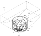
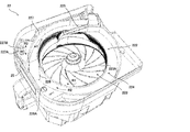
- variable cassette 22 when the first rotating body 223 is rotated in the rotation direction R ⁇ b> 1 (see FIGS. 4 and 5), the tablets in the tablet accommodating part 222 are moved from the first rotating body 223 to the second rotating body 223. It is discharged to the rotating body 224.
- the second rotating body 224 when the second rotating body 224 is rotated in the rotation direction R ⁇ b> 2 (see FIGS. 4 and 5), the tablets on the second rotating body 224 are transported toward the payout opening 225. Is done.
- the tablets stacked in the height direction come into contact with the height regulating member 226 and are returned to the tablet accommodating portion 222.
- the tablets conveyed side by side in the width direction come into contact with the width regulating member 227 and are returned to the tablet container 222.
- the tablet having a size corresponding to the height h ⁇ b> 1 regulated by the height regulating unit 226 and the width w ⁇ b> 1 regulated by the width regulating member 227 is the second rotating body 224.
- the tablets are transported to the payout opening 225 in a state where one tablet is arranged in the circumferential direction. Therefore, in the variable cassette 22, the tablets stored in the tablet storage unit 222 can be discharged in units of one tablet, and the discharge amount of the tablets can be controlled.
- variable cassette 22 the height h1 regulated by the height regulating member 226 and the width w1 regulated by the width regulating member 227 can be changed. It is possible to dispense tablets in units of one tablet.
- each of the variable cassettes 22 incorporates an RFID tag 26 for storing various information.
- the RFID tag 26 is a nonvolatile recording medium in which stored information can be rewritten by the RFID reader / writer 245.
- the RFID tag 26 is assigned to each cassette identification information of the variable cassette 22 and each of the variable cassettes 22. It is used for storing the received drug information and the like.
- the RFID tag 26 is mounted on a control board provided in each of the variable cassettes 22, and the control board displays the display of the display unit 25 of the variable cassette 22 according to a control signal from the prescription control unit 1. It also has a function to change.
- the control board is supplied with power supplied via the connector, power supplied from a power storage unit such as a battery mounted on the control board, or when writing information to the RFID tag 26.
- a power storage unit such as a battery mounted on the control board
- An electric circuit driven by electric power is mounted.
- each of the variable cassettes 22 may have another recording medium such as an EEPROM that allows the prescription control unit 1 to read and write information via the connector instead of the RFID tag 26. Is considered.
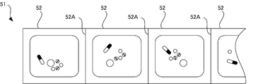
- FIG. 8 is a view showing an example of the medicine package sheet 51 discharged from the packaging unit 5.
- a plurality of wrapping papers 52 in which a plurality of tablets are packaged in the wrapping unit are continuously formed on the medicine wrapping sheet 51, A cut dotted line 52A (perforation) for easily separating each of the wrapping papers 52 is formed.
- the powder supplied from the powder supply unit 3 can be packed in the packing paper 52 in the packaging unit 5.
- the packaging unit 5 is provided with a printing unit (not shown) for printing information on each of the packaging papers 52, and the printing unit (not shown) is provided on the surface of each of the packaging papers 52.
- Can print prescription information such as the patient's name, time of use, prescription drugs, or prescription amount.
- the packaging control unit 6 includes a control unit 61 and a storage unit 62, and includes the tablet supply unit 2, the powder supply unit 3, the handing unit 4, and the packaging unit 5. Is controlled to cause the medicine dispensing apparatus 100 to execute a packaging operation.
- the packaging control unit 6 is built in the medicine dispensing apparatus 100.
- the storage unit 62 is a storage unit such as a hard disk device or an SSD (Solid State Drive) that stores various data. Specifically, the storage unit 62 stores in advance a first medicine dispensing program for causing a computer such as the control unit 61 to execute a below-described packaging control process (see the right side of FIG. 11).
- the first medicine dispensing program is recorded on a computer-readable recording medium such as a CD, a DVD, or a semiconductor memory, and is read from the recording medium by a reading device such as a disk drive (not shown). Installed in the storage unit 12.
- the present invention can be understood as an invention of the computer-readable recording medium in which the first medicine dispensing program is recorded.
- the bar code reader 7 reads a code for identifying a medicine, and is a JAN code or RSS code written on a container (box, bottle, etc.) for tablets provided on a medicine shelf of a pharmacy or a PTP sheet. Or a portable terminal such as a PDA that reads a QR code (registered trademark).
- the bar code reader 7 may be a conventionally known picking auxiliary device used by a pharmacist or the like for picking medicine.
- the picking assist device is used when a pharmacist or the like takes out a medicine from a medicine shelf according to a prescription and manually dispenses the medicine, for example, reads the medicine from a JAN code written in the container, and reads the medicine Check against prescription data.
- the information read by the bar code reader 7 is input from the bar code reader 7 to the prescription control unit 1 by wireless communication. If wireless communication is used in this way, the barcode reader 7 can be freely carried to the medicine dispensing device 100 or the medicine shelf, and the tablet loading operation to the variable cassette 22 is performed at an arbitrary place. It is also possible. Of course, it is also conceivable that the barcode reader 7 is connected to the prescription control unit 1 by wire. When a plurality of the medicine dispensing devices 100 are provided in the pharmacy, the barcode reader 7 associated with each of the medicine dispensing devices 100 is provided individually.
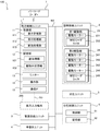
- the prescription control unit 1 is a computer that comprehensively controls the medicine dispensing apparatus 100. As shown in FIGS. 1 and 2, the prescription control unit 1 includes a control unit 11, a storage unit 12, a monitor 13, an operation unit 14, a communication IF 15, and the like.
- the control unit 11 is a control means having a CPU, RAM, ROM, EEPROM and the like.
- the control unit 11 executes various processes according to various programs stored in advance in a storage unit such as the ROM, the EEPROM, or the storage unit 12 by the CPU.
- the CPU is a processor that executes various processes, and the RAM and the EEPROM are used as a temporary storage memory (working area) for various processes executed by the CPU.
- the control unit 11 may be an integrated circuit such as an ASIC or a DSP.
- the storage unit 12 is a storage unit such as a hard disk device or an SSD (Solid State Drive) that stores various data. Specifically, the storage unit 12 stores in advance a second medicine dispensing program for causing a computer such as the control unit 11 to execute a medicine dispensing process (see the left side of FIG. 11) described later.
- a second medicine dispensing program for causing a computer such as the control unit 11 to execute a medicine dispensing process (see the left side of FIG. 11) described later.
- control unit 11 includes a display processing unit 111, a reception processing unit 112, and an allocation processing unit 113.
- the control unit 11 functions as the display processing unit 111, the reception processing unit 112, and the allocation processing unit 113 by executing various processes according to the second medicine dispensing program.
- the display processing unit 111 has a plurality of selection areas for selecting each of the variable cassettes 22 for each of the variable cassettes 22 in the medicine dispensing apparatus 100. It is possible to display a selection screen displayed in the same array as the array.
- the reception processing unit 112 can receive a selection operation of the selection area on the selection screen. In addition, the reception processing unit 112 can receive an input operation of medicine information to be paid out.
- the allocation processing unit 113 can allocate medicine information to be dispensed to the variable cassette 22 corresponding to the selection area received by the reception processing unit 112.
- the second medicine dispensing program is recorded on a computer-readable recording medium such as a CD, a DVD, or a semiconductor memory, and is read from the recording medium by a reading device such as a disk drive (not shown). Installed in the storage unit 12.
- the present invention can be understood as an invention of the computer-readable recording medium in which the second medicine dispensing program is recorded.
- the first medicine dispensing program and the second medicine dispensing program are an example of a medicine dispensing program for causing the medicine dispensing apparatus 100 to execute various processes.
- the medicine dispensing device 100 does not have the packaging control unit 6 and the prescription control unit 1 also functions as the packaging control unit 6.
- a medicine dispensing program in which the first medicine dispensing program and the second medicine dispensing program are integrated is stored in the storage unit 12, and the control unit 11 is described later according to the medicine dispensing program. It is conceivable to execute a medicine dispensing process and a packaging control process.
- the present invention can also be understood as an invention of the computer-readable recording medium in which the medicine dispensing program is recorded.
- the storage unit 12 also stores various databases such as a pharmaceutical master, a patient master, a cassette master, and a pharmacy master.
- the control unit 11 is configured to store the various types of data stored in the storage unit 12 based on data read from a recording medium such as a CD, a DVD, or a semiconductor memory by a reading device such as a disk drive (not shown). It is possible to update the database.
- the control unit 11 can change the contents of the various databases in accordance with a user operation on the operation unit 14.
- the cassette master is information indicating the correspondence between the cassette identification information of each fixed cassette 21 and the medicine information assigned to each fixed cassette 21.
- the cassette master is registered by the control unit 11 according to a user operation of the operation unit 14 in an initial setting of the medicine dispensing apparatus 100, for example.
- the storage unit 12 includes allocation information 121 indicating an allocation state between the variable cassette 22 and the medicine information, and drive correspondence information 122 indicating a correspondence relationship between the medicine information and the driving conditions of the variable cassette 22. It is remembered.
- the allocation information 121 and the drive correspondence information 122 are used in a medicine dispensing process, which will be described later, executed by the control unit 11.
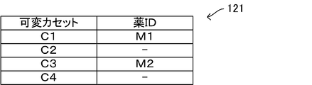
- FIG. 9 is a diagram illustrating an example of the allocation information 121
- FIG. 10 is a diagram illustrating an example of the drive correspondence information 122.
- a medicine ID indicating the type of tablet currently assigned to each variable cassette 22 is stored as medicine information.
- medicine information such as tablet name, medicine code, JAN code (or RSS code) may be stored.
- cassette numbers “C1” to “C4” are preset as the cassette identification information in the four variable cassettes 22 arranged in order from left to right in the tablet supply unit 2. To do.
- the cassette identification information is also stored in the RFID tag 26 of each variable cassette 22.
- the allocation information 121 it is stored that the variable cassette 22 to which no drug information is currently allocated is not allocated. Specifically, in the allocation information 121 shown in FIG.
- the medicine information of medicine ID “M1” is stored in the cassette number “C1” of the variable cassette 22, and the medicine of medicine ID “M2” is stored in the cassette number “C3”. Information is allocated, and the cassette numbers “C2” and “C4” indicate that chemical information is not yet allocated.
- the data structure of the allocation information 121 shown in FIG. 9 is merely an example, and the allocation information 121 may be stored in the storage unit 12 as one item of the medicine master, for example. In this case, the cassette identification information of the variable cassette 22 assigned to the medicine is stored in association with each medicine included in the medicine master.
- the driving correspondence information 122 stores driving conditions set in advance corresponding to each medicine information.
- the driving conditions include pre-driving conditions relating to adjustment of the variable cassette 22 before starting dispensing of tablets from the variable cassette 22, driving conditions relating to drive control during dispensing of tablets from the variable cassette 22, and Three types of conditions, that is, a driving stop condition relating to driving control when stopping the dispensing of tablets from the variable cassette 22 are included.
- the drive condition corresponding to each tablet whose medicine ID is “M1”, “M2”, “M3”, “M4”, Information about each item of height, the width of the payout path, the payout speed, the first slowdown, the second slowdown, and the reverse rotation operation is stored.
- the driving conditions are merely examples.
- the vibration frequency or amplitude of the vibration is determined as the driving conditions. It is possible.
- the height of the payout path and the width of the payout path are examples of the pre-driving conditions, and the tablets are discharged from the payout opening 225 one by one by the second rotating body 224 of the variable cassette 22. Is a value of the height h1 and the width w1 (see FIG. 5) set in advance as possible values.
- the dispensing speed is an example of the driving condition, and is a rotational speed suitable for each medicine information as the rotational speed of the second rotating body 224 when the tablet is dispensed from the variable cassette 22. For example, if the size of the tablet is small, if the rotational speed of the drive motor 242 is high, the tablet is likely to be dispensed excessively until the drive motor 242 stops. On the other hand, if the size of the tablet is large, even if the rotational speed of the drive motor 242 is high, the tablet is not dispensed excessively until the drive motor 242 stops.
- the tablet dispensing speed set as the driving condition that is, the tablet conveyance speed by the second rotating body 224 varies depending on the size of the tablet.
- the dispensing speed when the tablet size is large is set to a faster value than the dispensing speed when the tablet size is small.
- the payout speed is not limited to the [lock / min] format shown in FIG. 10, but may be stored in a format such as the rotational speed of the second rotating body 224 or the rotational speed of the drive motor 242. .
- the first slowdown and the second slowdown are examples of the driving stop condition, and when the tablet dispensing from the variable cassette 22 is stopped, the rotational speed of the second rotating body 224 is gradually increased. It is the information regarding the execution timing of slowdown that decelerates.
- the first slowdown defines a timing at which the rotational speed of the second rotating body 224 is decelerated to a predetermined first rotational speed.
- the second slowdown defines a timing at which the rotational speed of the second rotating body 224 is decelerated from the first rotational speed to a slower second rotational speed. For example, if the shape of the tablet contained in the variable cassette 22 is round and easy to roll, the tablet may roll out and be dispensed after the driving of the second rotating body 224 is stopped.
- the start timing of each of the first slowdown and the second slowdown is set earlier.
- the start timing of the first slowdown and the second slowdown is set by the remaining number of tablets to be dispensed from the variable cassette 22. Thereby, it is possible to prevent extra tablets from being dispensed when the dispensing of the tablets from the variable cassette 22 is stopped.
- the start timing of the first slowdown and the second slowdown is set late for a tablet that is difficult to roll when the driving of the second rotating body 224 is stopped, the unnecessary slowdown is performed. The delay of the payout time due to is suppressed.
- the start timing of the first slowdown and the second slowdown is set as the driving stop condition.
- the rotational speed of the second rotating body 224 is reduced. It is also conceivable that the speed is set as the driving stop condition. For example, for a tablet having a shape such as a sphere that is easy to roll, if the second rotating body 224 is suddenly stopped, there is a risk that it will roll over and be dispensed extra. For this reason, for example, for tablets that are easy to roll, it is conceivable to set the deceleration small.
- the data structure of the drive correspondence information 122 shown in FIG. 10 is merely an example, and the drive condition defined by the drive correspondence information 122 is stored in the storage unit 12 as one item of the medicine master, for example. It may be what was done.
- the medicine dispensing apparatus 100 determines any one or more of the items of the height of the dispensing path, the width of the dispensing path, the dispensing speed, the first slow down, the second slow down, and the reverse rotation operation as the driving condition. It is conceivable as another embodiment.
- one or more of the pre-driving condition, the driving condition, and the driving stop condition are set in advance as the driving condition corresponding to each medicine information. It is possible. In addition, a plurality of conditions such as the pre-driving condition, the driving condition, and the driving stop condition are set in advance as the driving condition corresponding to each medicine information, and are used in the medicine dispensing apparatus 100. A configuration is also conceivable in which any one or a plurality of conditions such as the pre-driving condition, the driving condition, and the driving stop condition can be selected as the driving condition.
- the operation unit 14 is an operation unit such as a keyboard, a mouse, and a touch panel that accepts a user operation, and inputs an operation signal corresponding to the user operation to the control unit 11.
- the operation unit 14 is, for example, a prescription data input operation on the input screen displayed on the monitor 13, a prescription data selection operation on the selection screen, a variable cassette 22 selection operation on the selection screen, and the prescription data It is a touch panel which receives various operation inputs, such as issuing operation of prescription data which requests the start of packaging.
- the communication IF 15 is a communication interface for connecting the medicine dispensing apparatus 100 to a communication network N3 such as a LAN, and is connected to a host system such as a prescription input terminal 200 connected via the communication network N3. Execute data communication.
- the prescription input terminal 200 is, for example, an electronic medical record system disposed in a hospital or a health facility, a dispensing management system disposed in a hospital or an out-of-hospital pharmacy, or the like.
- the communication IF 15 also includes a wireless communication interface such as a wireless communication card for performing wireless data communication with various wireless communication devices such as the barcode reader 7.
- control unit 11 shifts the processing to the step S11.
- the control unit 11 judges that there existed the issuing request
- the control unit 11 receives the prescription data from a higher system such as the prescription input terminal 200, the control unit 11 determines that there has been a request for issuing the prescription data without requiring the issuing operation, and the process is performed in step S2. It is conceivable as another embodiment to shift to the above.
- step S ⁇ b> 2 the control unit 11 determines whether or not there is the fixed cassette 21 corresponding to all medicine information input as medicine information indicating a tablet to be dispensed based on the prescription data. Specifically, the control unit 11 determines, based on the cassette master stored in the storage unit 12, whether or not a tablet not included in each of the fixed cassettes 21 is included in the prescription data as a prescription drug. To do.
- the cassette master is based on chemical information read from an RFID tag (not shown) provided in each fixed cassette 21 by a reading device such as the RFID reader / writer 232 provided in each mounting portion 211. It is updated by the control unit 11.
- the control unit 11 can display an edit screen for editing the cassette master on the monitor 13 and update the cassette master in accordance with a user operation of the operation unit 14 on the edit screen. is there.
- step S7 a request for starting the packaging operation similar to the conventional one is transmitted to the control unit 61 using each of the fixed cassettes 21, and the control unit 61 performs a process for executing the packaging operation. Executed.
- allocation exclusion medicine information preset as medicine information that does not execute assignment to the variable cassette 22 is stored in the storage unit 12. Then, when the control unit 11 does not have the fixed cassette 21 corresponding to the medicine information to be dispensed and the medicine information to be dispensed corresponds to the allotted medicine information, the control unit 11 moves to the variable cassette 22. It is conceivable to display on the monitor 13 that the manual handling unit 4 should be used without executing the assignment. For example, if a tablet with a high possibility of colored powder adhering to the variable cassette 22 is set as the allotment-excluded medicine information, the colored powder adheres to the tablet accommodated in the variable cassette 22 next. Can be prevented.
- the hand-rolling unit 4 should be used for medicines and the like that are not properly dispensed by the variable cassette 22. Whether or not the medicine information to be dispensed corresponds to the allotted medicine information without the control unit 11 determining whether or not the fixed cassette 21 corresponding to the medicine information to be dispensed exists. It can be considered as another embodiment. In this case, when the medicine information to be dispensed corresponds to the allotted medicine information, the control unit 11 indicates that the handing unit 4 should be used without performing the assignment to the variable cassette 22. Displaying on the monitor 13 is also conceivable as another embodiment.
- step S ⁇ b> 3 the control unit 11 assigns medicine information for which the corresponding fixed cassette 21 does not exist among the medicine information to be dispensed input by the prescription data to the unallocated variable cassette 22.
- the said control part 11 performs allocation of the said variable cassette 22 about each of the chemical
- control unit 11 executes a process of specifying the variable cassette 22 that is currently communicable (controllable) among the variable cassettes 22. For example, the control unit 11 determines that the variable cassette 22 of the variable cassette 22 that has been successfully read from the RFID tag 26 by the RFID reader / writer 245 is in a communicable state.
- the said control part 11 judges the presence or absence of the allocation of the present chemical
- medical agent information of the payout target Are assigned to the unallocated variable cassette 22.
- the control unit 11 determines the variable cassette 22 to which the medicine information is allocated, the control unit 11 updates the content of the allocation information 121 according to the allocation result.
- the variable cassette 22 assigned to the medicine information can communicate with the control unit 11, and information can be written on the electronic paper 25 by the control unit 11.
- the control unit 11 may set each variable cassette 22 as a candidate for allocation without determining whether or not each variable cassette 22 can communicate.
- the control unit 11 determines whether or not the medicine information is assigned based on a preset priority order among the variable cassettes 22, and the variable cassette that is initially determined to be unassigned. It is conceivable that the medicine information is assigned to 22. In addition, the control unit 11 determines whether or not the medicine information is allocated in order from the lowest usage count of the variable cassette 22 so that the usage count of each of the variable cassettes 22 becomes equal, and the unallocated first. It is also conceivable to assign the medicine information to the variable cassette 22 determined to be.
- control unit 11 selects the variable cassette 22 in which the medicine information assigned immediately before of each of the variable cassettes 22 is the medicine information that is the same as the medicine information to be assigned this time or the tablet size is close. It is also possible. When there is no unallocated variable cassette 22, the control unit 11 notifies the user by displaying the fact on the monitor 13.
- step S3 the control unit 11 controls the RFID reader / writer 245 to assign the variable cassette 22 to the RFID tag 26 of each of the variable cassettes 22 to which the medicine information is assigned. Record the drug information.
- the control unit 11 based on the prescription data, together with the medicine information, various kinds of information such as a tablet dispensing amount indicated by the medicine information, a patient name, an assigned date, a pharmacist name in charge, and identification information of a prescription. It is also possible to record it.
- the medicine information is not recorded on the RFID tag 26 of the variable cassette 22.
- the cassette identification information is recorded in advance in the RFID tag 26 and the RFID reader / writer 245 is an RFID reader that can only read information. Even in this case, the controller 11 recognizes the medicine information assigned to the variable cassette 22 based on the cassette identification information read from the RFID tag 26 and the assignment information (see FIG. 9). Is possible.
- Step S11 the control unit 11 determines whether or not a request operation for starting manual input of prescription data using the operation unit 14 has been performed. to decide. For example, the control unit 11 determines that the request operation has been performed when a prescription input start key displayed on the display screen of the monitor 13 is operated. If it is determined that the requested operation has been performed (S11: Yes), the process proceeds to step S12. If it is determined that the requested operation has not been performed (S11: No), the process is performed as described above. It returns to step S1.
- step S ⁇ b> 12 the control unit 11 displays an input screen for inputting the prescription data on the monitor 13, and accepts input of the prescription data in response to a user operation on the operation unit 14.
- the reception process is executed by the reception processing unit 112 of the control unit 11.
- the content of the prescription data input here includes information on one medicine to be dispensed, and the dosage and usage of the medicine information. That is, in the steps S12 to S15, processing is executed individually for each medicine information.
- the drug information may be read by the barcode reader 7 from a tablet container or a PTP sheet. And if the said prescription data is input, a process will transfer to step S13.
- step S ⁇ b> 13 the control unit 11 causes the monitor 13 to select a cassette to be used for dispensing medicines to be dispensed corresponding to the medicine information from the plurality of fixed cassettes 21 and variable cassettes 22. P1 is displayed. Such display processing is executed by the display processing unit 111. FIG. 13 shows an example of the selection screen P1.
- the numbers of the specific area A1 and the selection area A2 displayed on the selection screen P1 in FIG. 13 are the maximum display numbers.
- the display of the specific area A1 and the selection area A2 corresponding to the mounting portion 211 and the mounting portion 221 where the fixed cassette 21 or the variable cassette 22 is not mounted may be omitted.
- a specific symbol such as a display frame is displayed instead of the specific area A1 or the selection area A2. That is, the specific area A1 and the selection area A2 may be displayed in the same arrangement as the arrangement of the attachment section 211 and the attachment section 221.
- control unit 11 determines the drug information about the specific region A1 or the selection region A2 corresponding to the mounting unit 211 or the mounting unit 221 to which the fixed cassette 21 or the variable cassette 22 is not mounted. It is conceivable that no selection operation is accepted without displaying.
- control unit 11 displays the surrounding line L1 around the selection area A2 corresponding to the variable cassette 22 on the selection screen P1, so that the selection area A2 corresponding to the variable cassette 22 and the selection area A2
- the specific area A1 corresponding to the fixed cassette 21 is displayed in an identifiable manner.
- the control unit 11 can identify by the difference in not only the said surrounding line L1, but a background color or a size, for example. There may be.
- Information for identifying which of the variable cassette 22 and the fixed cassette 21 is associated may be displayed in association with the selection area A2 and the specific area A1. Further, even if information indicating whether the cassette type is the variable cassette 22 or the fixed cassette 21 is displayed in the individual display area corresponding to each of the variable cassette 22 and the fixed cassette 21 on the selection screen P1. Good.
- the specific area A1 corresponding to the fixed cassette 21 may not be displayed, and only the selection area A2 corresponding to the variable cassette 22 may be displayed. That is, when the prescription data is manually input, the variable cassette 22 may be always selected.
- the control unit 11 displays a first display state in which both the selection area A2 and the specific area A1 are displayed on the selection screen P1, and a second display state in which only the selection area A2 is displayed. It may be switchable according to the operation. Furthermore, the control unit 11 displays both the selection area A2 and the specific area A1 when there is the fixed cassette 21 from which the medicine of the medicine information input in step S12 can be dispensed.
- control unit 11 may omit the steps S13 to S15 when there is the fixed cassette 21 to which the medicine of the medicine information input in the step S12 can be dispensed. That is, when there is the fixed cassette 21 that can dispense medicine corresponding to the medicine information input in step S12, the stationary cassette 21 is automatically selected as a cassette used for dispensing medicine. Also good. In this case, it is also conceivable that the control unit 11 accepts selection of an arbitrary variable cassette 22 by a user operation and assigns the medicine information to the selected variable cassette 22.
- the control unit 11 displays the fixed cassette 21 or the variable cassette on the selection screen P1. It is conceivable that the specific area A1 or the selection area A2 corresponding to the cassette 22 is highlighted. For example, it is conceivable to change the character color or background color of the specific area A1 or the selection area A2 corresponding to the fixed cassette 21 or the variable cassette 22 to a predetermined red color or the like. Thereby, the user can easily grasp whether or not the fixed cassette 21 or the variable cassette 22 capable of dispensing the medicine corresponding to the medicine information exists.
- the highlighted display mode is not limited to the display color difference as long as it can be distinguished from the other fixed cassette 21 or variable cassette 22.
- control unit 11 displays an allocation state indicating the allocation status of medicine information for each of the selection areas A2 in each of the selection areas A2.
- “unassigned” is displayed in the selection area A2 corresponding to the variable cassette 22 to which no drug information is assigned.
- the medicine information is not assigned because the selection area A2 is blank.
- the state of the selected area A2 is displayed such that the assigned area is blue, the unassigned area is red, etc., so that the state can be identified by color.
- the medicine name corresponding to the assigned medicine information is displayed, so that the medicine information has already been assigned. And the type of the assigned medicine are displayed.
- “assigned” may be displayed in the selection area A2 corresponding to the assigned variable cassette 22.
- step S14 the control unit 11 accepts a selection operation of the selection area A2 or the specific area A1 on the selection screen P1.
- the reception process is executed by the reception processing unit 112. Specifically, when the operation unit 14 is a touch panel provided on the monitor 13, the control unit 11 selects the selection region A 2 by touching the selection region A 2 or the specific region A 1 on the monitor 13. Accept as an operation.
- the control unit 11 moves the mouse pointer to the selection area A2 or the specific area A1 on the monitor 13 and performs a click operation on the selection area A2 or the specific area. Accepted as the selection operation of A1.
- the control unit 11 displays the cassette identification information of each of the variable cassettes 22 and the setting contents of the driving conditions corresponding to each of the variable cassettes 22 on the monitor 13 in accordance with a user operation on the operation unit 14.
- Changing the setting contents of the driving condition is also conceivable as another embodiment.
- the change contents of the driving condition are notified from the control unit 11 to the control unit 61.
- the driving condition of the variable cassette 22 when the tablet is dispensed from the variable cassette 22 by an arbitrary operation input by the user.
- the user can check the setting contents of the driving condition corresponding to the medicine information to be dispensed by referring to the monitor 13.
- step S ⁇ b> 22 the control unit 61 drives the variable cassette 22 to which the medicine information is assigned according to the driving condition so that the medicine corresponding to the medicine information can be dispensed from the variable cassette 22.
- the variable cassette 22 corresponding to the cassette identification information received together with the drive condition is driven according to the advance drive condition among the drive conditions, and the height of the payout path and the width of the payout path are set. change.
- the control unit 61 changes the variable according to the pre-driving condition (height and width of the dispensing path).
- the cassette 22 is driven, and thereafter, the tablet is dispensed from the variable cassette 22 (S24).
- the control unit 61 stores flag information indicating whether or not the driving condition received from the control unit 11 is reflected in the variable cassette 22 in the storage unit 62 and updates it as needed. Then, the control unit 61 refers to the flag information at the start of the packaging operation in step S24 described later, and when the driving condition is not reflected on the variable cassette 22 used in the packaging operation. Before executing the packaging operation, the variable cassette 22 is driven according to the pre-driving condition, and the height h1 and the width w1 of the payout path are changed.
- step S ⁇ b> 6 the control unit 11 determines whether or not a filling completion operation indicating that the filling of the tablet into the variable cassette 22 is completed has been performed on the operation unit 14. Specifically, when the medicine information is assigned to the variable cassette 22 in the step S3 or S15 and the medicine information is displayed on the display unit 25 of the variable cassette 22, the user moves the variable cassette 22 to the variable cassette 22. Remove from the tablet supply unit 2. Then, the user puts the necessary number of tablets into the variable cassette 22 while referring to the prescription corresponding to the prescription data or the medicine information displayed on the display unit 25 in the variable cassette 22.
- control part 11 specifies each said variable cassette 22 in which the tablet which each said medicine information shows among the said variable cassettes 22 was accommodated based on the said prescription data based on the said prescription data. Thereafter, the control unit 11 includes, for each of the drug information indicated in the prescription data, cassette identification information of the variable cassette 22 to which the drug information is assigned, and the mounting unit 221 to which the variable cassette 22 is mounted. Information necessary for the packaging operation, such as the identification information and the dispensed amount of the tablet, is transmitted to the control unit 61.
- the rotational speed of the drive motor 242 is further reduced to the second rotational speed.
- the control unit 61 does not need the reverse rotation operation when stopping the dispensing of the tablet from the variable cassette 22. Do not execute.
- the reverse rotation operation may be started when the number of locks counted by the counter reaches a value that is a predetermined number less than the dispensed amount.
- the predetermined number corresponding to each medicine information may be stored in advance in the drive correspondence information 122.
- the reverse rotation operation can be started before the number of tablets counted by the counter reaches the amount to be dispensed, and excessive dispensing of the tablets from the dispensing outlet 225 can be prevented.
- the reverse rotation operation is started each time one tablet is dispensed.
- the medicine dispensing apparatus 100 is provided with a plurality of the variable cassettes 22, different medicine information can be assigned to each of the variable cassettes 22. Therefore, in the medicine dispensing apparatus 100, even when a plurality of tablets that are not in the fixed cassette 21 are included in the prescription data, the packaging operation based on the prescription data is performed using the plurality of variable cassettes 22. Can be executed. In the medicine dispensing apparatus 100, it is also possible to continuously execute a packaging operation based on a plurality of the prescription data using the plurality of variable cassettes 22.
- the tablets may remain in the variable cassette 22, and a user such as a pharmacist collects the tablets and collects the medicine bottles, etc. May be returned to the chemical container.
- a medicine dispensing apparatus 100A capable of easily collecting tablets from the variable cassette 22 will be described.
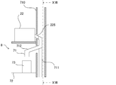
- FIG. 15 to 17 are schematic diagrams for explaining an example of the structure of the recovery unit 8.
- FIG. 15 is a schematic diagram showing a configuration of a main part of a connecting portion between the payout opening 225 of the variable cassette 22 and the recovery unit 8
- FIG. 16 is a schematic diagram showing a side cross section of the recovery unit 8
- FIG. 2 is a schematic diagram when the recovery unit 8 is viewed in the XVII-XVII direction.
- the wall portion 710 (see FIG. 16) provided on the back side of the mounting portion 221 in the tablet supply unit 2 is omitted.
- step S ⁇ b> 32 the control unit 11 transmits an execution request for the collection process to the control unit 61. Thereby, the collection process is executed by the control unit 61. That is, in the medicine dispensing process, the control unit 61 can execute the collection process after the dispensing of the tablets from the variable cassette 22 accompanying the tablet packaging operation by the packaging unit 5 is completed. .
- step S26 the control unit 61 determines whether or not there is an execution request for the recovery process in step S26, and if the execution request for the recovery process is received from the control unit 11 (Yes side of S26), The process proceeds to step S27. On the other hand, when the execution request for the collection process has not been received from the control unit 11 (No in S26), the process returns to step S21.
- step S ⁇ b> 27 the control unit 61 executes a collection process for collecting tablets from the variable cassette 22. Specifically, the control unit 61 controls the path switching unit 713 to switch the discharge destination of the tablet dispensed from the variable cassette 22 from the packaging unit 5 to the collection port 71 and is set in advance. The first rotating body 223 and the second rotating body 224 of the variable cassette 22 are driven for a predetermined time to dispense the tablets from the variable cassette 22.
- recovery process which concerns here is an example of a collection
- the collection unit 8 includes a discharge switching unit 720 that can switch between a state in which the medicine dispensed from the variable cassette 22 to the collection port 71 is stored and a state in which the medicine can be discharged from the collection port 71. It is possible.
- the discharge switching part 720 includes an opening / closing part 714 that can open and close the recovery port 71, and a biasing part 715 such as a spring that biases the opening / closing part 714 in a closing direction.
- a biasing part 715 such as a spring that biases the opening / closing part 714 in a closing direction.
- the opening / closing part 714 is opened by a part of the opening edge of the medicine container 73 coming into contact with the opening / closing part 714 by the sliding movement of the medicine container 73. May be.
- a configuration in which the opening / closing unit 714 can be opened / closed by a driving unit such as a solenoid or a motor, and the control unit 11 can open / close the opening / closing unit 714 in accordance with a user operation is also conceivable as another embodiment.
- the discharge switching unit 720 may not include the biasing unit 715, and the opening / closing unit 714 may be manually opened / closed.
- variable cassette 22 is provided with the display unit 25 such as electronic paper, and the display unit 25 includes a drug name of a tablet as drug information assigned to the variable cassette 22. Etc. are displayed.
- the variable cassette 22 and the recovery port 71 corresponding to the variable cassette 22 are arranged side by side in the vertical direction. Therefore, a user such as a pharmacist can easily confirm that the medicines match by looking at the display unit 25 of the variable cassette 22 and the medicine container 73 set below the variable cassette 22. Yes, erroneous collection of the tablets into the medicine container 73 is suppressed.
- the medicine dispensing apparatus 100A is provided with an image forming apparatus such as a printer or a label printing apparatus, or the image forming apparatus is connected to be communicable.
- the control unit 11 uses the image forming apparatus to provide information such as the number of tablets, drug information, and the collection operation date / time as information on the tablet collection record using the collection port 71. May be printed.
- the medicine container 73 is provided with a storage medium such as an RFID chip, and the recovery unit 8 includes an RFID reader / writer that can read and write information from and to the storage medium of the medicine container 73. Configuration is conceivable. In this case, it may be considered that the control unit 11 stores the information of the collection record in the storage medium of the medicine container 73.
- the display unit 25 displays that fact. Can be considered. This makes it possible to more reliably recognize that the tablet is a powerful drug or poison when collecting the tablet from the variable cassette 22, and perform the recovery operation without knowing that the tablet is a powerful drug or poison. It is possible to reduce the risk of doing it.
- the collection port 71 is individually provided corresponding to each of the mounting portions 221, and the tablets of each of the variable cassettes 22 can be individually collected. Therefore, the operation of sorting the tablets dispensed from the collection port 71 is omitted.
- one collection port 71 is provided corresponding to the mounting portions 221 of at least two or more variable cassettes 22. That is, a configuration in which the tablets supplied from the plurality of mounting portions 221 are paid out from the common collection port 71 via the common second path 712 is also conceivable.
- the control unit 11 can select whether to perform the payout from each of the variable cassettes 22 or to simultaneously execute the payout from the plurality of variable cassettes 22. It is thought that it is. Accordingly, the user can collect the tablets for each of the variable cassettes 22 and can collect the tablets from the plurality of variable cassettes 22, thereby improving convenience.
- the medicine dispensing device 100A since the first path 711 and the second path 712 can be switched for each variable cassette 22, the tablet is dispensed from the variable cassette 22 to the collection port 71. It is also possible to perform the packaging operation using the variable cassette 22 that is not subject to the test payout process while performing the test payout process for testing whether or not the tablet can be discharged from the variable cassette 22. It is.
- an optical sensor or the like for detecting the medicine in the variable cassette 22 is provided in the variable cassette 22, and the controller 11 determines whether or not there is a medicine in the variable cassette 22 based on the detection result by the optical sensor. Can be considered.
- the variable cassette 22 includes an acceleration sensor that can detect the operation of the variable cassette 22, a control unit that controls the acceleration sensor, a secondary battery that drives the acceleration sensor and the control unit, and the like. It is conceivable that a power supply circuit is provided. Note that part or all of the configuration of the control unit, the power supply circuit, and the like may be common to the control board on which the RFID tag 26 provided in the variable cassette 22 is mounted.
- step S31 the control unit 11 can accept an operation input indicating whether or not the recovery process is necessary when there is a remaining medicine in the variable cassette 22, and there is a remaining medicine in the variable cassette 22. If not, a configuration in which an operation input indicating whether the collection process is necessary is not accepted is also conceivable.
- the control unit 11 may display a message on the monitor 13 for inquiring whether the collection process is necessary or not when there is a remaining medicine in the variable cassette 22. Also in this case, the user can easily grasp the presence / absence of the remaining medicine in each of the variable cassettes 22 and determine whether or not the collection processing for the variable cassettes 22 is necessary.
- control unit 11 assigns medicine information included in the prescription data to the variable cassette 22 in the step S3 or S15, a predetermined number of tablets dispensed corresponding to the medicine information is set in advance. When the number of tablets is exceeded, the drug information is assigned to the plurality of variable cassettes 22.
- the said control part 11 preset the product of the volume per tablet of the tablet registered into the said pharmaceutical master etc. corresponding to the said chemical
- control unit 11 includes an abnormal mounting determination function that can determine whether the correspondence relationship between the variable cassette 22 and the mounting unit 221 is appropriate.
- the target to which the drug information is assigned in step S15 is limited to the variable cassette 22 mounted on the mounting unit 221.
- the control unit 11 stores the correspondence information in which the identification information of the variable cassette 22 to which the medicine information is assigned is associated with the identification information of the mounting unit 221 to which the variable cassette 22 is mounted. It is conceivable to store in the unit 12.
- the control unit 11 determines an abnormality in the correspondence between the medicine cassette and the mounting unit based on the correspondence information. Specifically, the control unit 11 determines that an abnormality has occurred when a variable cassette 22 different from the variable cassette 22 associated with the mounting unit 221 is mounted on the mounting unit 221. And when the said abnormality is detected, the said control part 11 performs an error alerting
- control unit 11 deletes the correspondence information about the variable cassette 22 and releases the correspondence corresponding to the mounting unit 221.
- any of the variable cassettes 22 may be mountable with respect to the mounting portion 221 in which the correspondence relationship with the variable cassette 22 is not determined among the mounting portions 221.
- a medicine dispensing device comprising a plurality of medicine cassettes capable of dispensing any kind of medicine, A display processing unit for displaying a selection screen in which a plurality of selection areas for selecting each of the medicine cassettes are displayed in the same arrangement as the arrangement of each of the medicine cassettes in the medicine dispensing device; A reception processing unit that receives a selection operation of the selection area on the selection screen; An allocation processing unit that allocates medicine information to be dispensed to the medicine cassette corresponding to the selection area received by the reception processing unit; A drive processing unit that drives the medicine cassette according to driving conditions set in advance corresponding to the medicine information assigned by the assignment processing part, and puts the medicine cassette into a state in which the medicine corresponding to the medicine information can be dispensed.
- a chemical dispensing device comprising:
- Appendix 6 The medicine dispensing apparatus according to any one of appendices 1 to 5, wherein the acceptance processing unit accepts an input operation of medicine information to be dispensed after the selection operation is accepted.
- Appendix 7 6. The medicine dispensing apparatus according to any one of appendices 1 to 5, wherein the acceptance processing unit accepts an input operation of medicine information to be dispensed before the selection operation is accepted.
- Appendix 10 A packaging unit for packaging the medicine dispensed from the medicine cassette; A collection port for discharging the medicine dispensed from the medicine cassette to the outside; A path switching unit that switches a supply destination of a medicine to be dispensed from the medicine cassette to a first path following the packaging unit and a second path following the collection port;
- the medicine dispensing device according to any one of appendices 1 to 9, comprising:
Landscapes
- Health & Medical Sciences (AREA)
- General Health & Medical Sciences (AREA)
- Public Health (AREA)
- Pharmacology & Pharmacy (AREA)
- Life Sciences & Earth Sciences (AREA)
- Animal Behavior & Ethology (AREA)
- Veterinary Medicine (AREA)
- Chemical & Material Sciences (AREA)
- Medicinal Chemistry (AREA)
- Engineering & Computer Science (AREA)
- Bioinformatics & Cheminformatics (AREA)
- Toxicology (AREA)
- Epidemiology (AREA)
- Medical Informatics (AREA)
- Primary Health Care (AREA)
- Medical Preparation Storing Or Oral Administration Devices (AREA)
Abstract
Description
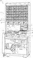
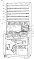
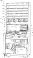
まず、図1及び図2を参照しつつ、本発明の第1実施形態に係る薬品払出装置100の概略構成について説明する。
前記錠剤供給ユニット2は、
予め定められた特定種類の錠剤を1錠(単位量)ごとに払出可能な複数の固定カセット21と、駆動条件の変更により任意の種類の錠剤を1錠(単位量)ごとに払出可能な複数の可変カセット22(薬品カセットの一例)とを備える。
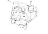
ここで、図3を参照しつつ、前記固定カセット21の一例について説明する。なお、ここで説明する前記固定カセット21の構造は一例に過ぎず、同様の機能を有するものであれば他の構造であってもよい。なお、図3は、前記固定カセット21の上部を覆うカバー部材を省略した図である。
次に、図4~図7を参照しつつ、前記可変カセット22の一例について説明する。なお、ここで説明する前記可変カセット22の構造は一例に過ぎず、任意の錠剤を1錠ずつ払い出すことが可能なものであれば他の構造であってもよい。例えば、特表2010-535683号公報又は特開2010-115493号公報には、前記可変カセット22の他の例が開示されている。
図1に示すように、前記散薬供給ユニット3は、二つの投入部31、32を備えており、前記投入部31、32各々に投入された散薬を、前記処方制御ユニット1により予め設定される服用時期などの分包単位で前記分包ユニット5に供給する。
前記手撒きユニット4は、予め設定された服用時期などの分包単位で錠剤が投入されるマスが複数設けられた手撒き収容部と、前記マス各々に収容された前記錠剤を前記マスごとに前記分包ユニット5に払い出す手撒き払出部とを備える。前記手撒き収容部では、複数の前記マスがマトリクス状に配置されている。前記手撒き払出部は、例えば前記手撒き収容部の前記マスの底面を個別に開閉することにより前記マスに収容された錠剤を払い出すことが可能な構成が考えられる。前記薬品払出装置100において、前記手撒きユニット4は、例えば1錠より小さい半錠などの錠剤を払い出すために用いられるものであり、従来周知であるためここでは説明を省略する。なお、従来、前記手撒きユニット4は、前記固定カセット21に予め収容されていない任意の錠剤を払い出す際にも用いられていたが、前記薬品払出装置100では、任意の錠剤は前記可変カセット22を利用して払い出すことが可能である。もちろん、前記固定カセット21に収容されていない任意の錠剤の払い出しに前記手撒きユニット4を用いることも可能である。
前記分包ユニット5は、前記錠剤供給ユニット2、前記散薬供給ユニット3、及び前記手撒きユニット4から供給された薬品を服用時期などの分包単位で一つの分包紙に収容する。例えば、前記分包ユニット5は、透明又は半透明のロール状の薬包シートにより前記分包単位で薬品を包装して溶着等により封止する。これにより、前記分包単位で薬品が収容された前記薬包シートが前記分包ユニット5から排出される。
前記分包制御ユニット6は、図2に示すように、制御部61及び記憶部62を備え、前記錠剤供給ユニット2、前記散薬供給ユニット3、前記手撒きユニット4、及び前記分包ユニット5などを制御することにより前記薬品払出装置100に分包動作を実行させる。なお、前記分包制御ユニット6は、前記薬品払出装置100に内蔵されている。
前記バーコードリーダー7は、薬品を識別するコードを読み取るものであり、薬局の薬品棚などに設けられた錠剤の収容容器(箱、瓶など)又はPTPシートなどに記載されたJANコード、RSSコード、又はQRコード(登録商標)を読み取る、例えばPDAなどの携帯端末である。なお、前記バーコードリーダー7は、例えば薬剤師などが薬品のピッキングに使用する従来周知のピッキング補助装置などであってもよい。前記ピッキング補助装置は、薬剤師等が処方箋に従って薬品棚から薬品を取り出して手動で調剤する際に用いられ、例えば、前記収容容器に記載されたJANコードから薬品を読み取って、その読み取られた薬品と処方データとの照合を行う。
前記処方制御ユニット1は、前記薬品払出装置100を統括的に制御するコンピュータである。図1及び図2に示すように、前記処方制御ユニット1は、制御部11、記憶部12、モニター13、操作部14、及び通信IF15等を備える。
以下、図11を参照しつつ、前記薬品払出装置100において、前記処方制御ユニット1の前記制御部11により実行される薬品払出処理及び前記分包制御ユニット6の前記制御部61により実行される分包制御処理の手順の一例について説明する。ここに、前記制御部11が実行する処理手順(ステップ)をステップS1、S2、・・・と称し、前記制御部61が実行する処理手順(ステップ)をステップS21、S22、・・・と称する。なお、前記制御部11及び前記制御部61のいずれか一方により前記薬品払出処理及び前記分包制御処理の処理結果と同様の処理結果が得られる一連の処理が実行されることも考えられる。
まず、ステップS1において、前記制御部11は、処方データの発行要求があったか否かを判断する。具体的に、前記制御部11は、予め登録された処方データを発行するための発行操作が前記操作部14に対して行われた場合に前記処方データの発行要求が行われたと判断する。前記処方データは、前記処方入力端末200等の上位システムから取得される。
次に、ステップS2において、前記制御部11は、前記処方データにより払出対象の錠剤を示す薬品情報として入力された全ての薬品情報に対応する前記固定カセット21が存在するか否かを判断する。具体的に、前記制御部11は、前記記憶部12に記憶されている前記カセットマスターに基づいて、前記固定カセット21各々にない錠剤が処方薬として前記処方データに含まれているか否かを判断する。なお、前記カセットマスターは、前記装着部211各々に設けられた前記RFIDリーダライタ232などの読取装置によって、前記固定カセット21各々に設けられたRFIDタグ(不図示)から読み取られる薬品情報に基づいて前記制御部11によって更新される。また、前記制御部11は、前記カセットマスターを編集するための編集画面を前記モニター13に表示させ、前記編集画面における前記操作部14のユーザー操作に応じて前記カセットマスターを更新することも可能である。
ステップS3において、前記制御部11は、前記処方データにより入力された払出対象の薬品情報のうち対応する前記固定カセット21が存在しない薬品情報を未割当の前記可変カセット22に割り当てる。なお、前記制御部11は、対応する前記固定カセット21が存在しない薬品情報が前記処方データに複数含まれている場合には、その薬品情報各々について前記可変カセット22の割り当てを実行する。
一方、前記処方データの発行要求がなされていない場合、続くステップS11において、前記制御部11は、前記操作部14を用いる処方データの手動入力を開始するための要求操作が行われたか否かを判断する。例えば、前記制御部11は、前記モニター13の表示画面に表示されている処方入力開始キーが操作された場合に前記要求操作が行われたと判断する。ここで、前記要求操作が行われたと判断されると(S11:Yes)、処理がステップS12に移行し、前記要求操作が行われていないと判断されると(S11:No)、処理が前記ステップS1に戻される。
ステップS12において、前記制御部11は、前記モニター13に前記処方データを入力するための入力画面を表示させ、前記操作部14に対するユーザー操作に応じて前記処方データの入力を受け付ける。なお、係る受付処理は、前記制御部11の受付処理部112によって実行される。
ステップS13において、前記制御部11は、前記モニター13に、複数の前記固定カセット21及び前記可変カセット22から前記薬品情報に対応する払出対象の薬品の払い出しに使用するカセットを選択するための選択画面P1を表示させる。なお、係る表示処理は前記表示処理部111によって実行される。ここに、図13は、前記選択画面P1の一例を示す図である。
ステップS14において、前記制御部11は、前記選択画面P1における前記選択領域A2又は前記特定領域A1の選択操作を受け付ける。なお、係る受付処理は前記受付処理部112によって実行される。具体的に、前記操作部14が前記モニター13に設けられたタッチパネルである場合、前記制御部11は、前記モニター13における前記選択領域A2又は前記特定領域A1のタッチ操作を前記選択領域A2の選択操作として受け付ける。また、前記操作部14がマウスである場合、前記制御部11は、前記モニター13における前記選択領域A2又は前記特定領域A1へのマウスのポインターの移動及びクリック操作を前記選択領域A2又は前記特定領域A1の選択操作として受け付ける。なお、前記選択画面P1では、現時点で薬品情報が未割当の前記可変カセット22だけではなく、前記薬品情報が既に割り当てられている前記可変カセット22を選択することも可能である。一方、前記薬品情報が未割当の前記可変カセット22のみが選択可能であることも他の実施形態として考えられる。
ステップS15において、前記制御部11は、前記ステップS14で前記可変カセット22が選択された場合には、前記ステップS12で入力された薬品情報を前記ステップS14で選択された前記可変カセット22に割り当て、処理をステップS16に移行させる。ここに、係る割当処理は前記割当処理部113によって実行される。具体的に、前記制御部11は、前記割当情報121の内容を更新し、前記薬品情報と前記可変カセット22とを対応付ける。例えば、前記可変カセット22に既に他の薬品情報が割り当てられている場合には、その薬品情報に代えて前記ステップS12で入力された薬品情報が割り当てられる。なお、前記ステップS14で前記固定カセット21が選択された場合、当該ステップS15は省略される。
ステップS16において、前記制御部11は、前記処方データの手動入力を終了するための要求操作が行われたか否かを判断する。例えば、前記制御部11は、前記モニター13の表示画面に表示されている処方入力終了キーが操作された場合に前記要求操作が行われたと判断する。ここで、前記要求操作が行われたと判断されると(S16:Yes)、処理がステップS4に移行する。一方、前記要求操作が行われず、例えば前記モニター13の表示画面に表示されている処方入力継続キーが操作された場合は(S16:No)、処理が前記ステップS12に戻されて同様の処理が繰り返し実行される。これにより、複数の前記薬品情報について前記処方データを入力すること及び前記可変カセット22を割り当てることが可能である。
ステップS4において、前記制御部11は、前記払出対象の薬品情報に対応する駆動条件を前記駆動対応情報122(図10参照)に基づいて特定し、前記駆動条件と前記薬品情報が割り当てられた前記可変カセット22のカセット識別情報とを前記制御部61に送信する。これにより、前記制御部61は、前記駆動条件に従って前記可変カセット22を駆動させることになる。このように前記ステップS4の処理を実行することにより前記可変カセット22を前記駆動条件に従って駆動させるときの前記制御部11を駆動処理部として捉えてもよい。
一方、前記分包制御ユニット6では、前記制御部61が、ステップS21において、前記制御部11からの前記駆動条件の受信の有無を判断する。ここで、前記制御部61は、前記駆動条件が受信された場合には(S21のYes側)、処理をステップS22に移行させ、前記駆動条件が受信されていない間は(S21のNo側)、処理をステップS23に移行させる。なお、前記制御部61は、前記制御部11から受信した前記駆動条件を、前記薬品情報が割り当てられた前記可変カセット22のカセット識別情報と対応付けて前記記憶部62に記憶する。
ステップS22において、前記制御部61は、前記薬品情報が割り当てられた前記可変カセット22を前記駆動条件に従って駆動させ、前記可変カセット22から前記薬品情報に対応する薬品を払い出し可能な状態にする。具体的に、前記駆動条件と共に受信した前記カセット識別情報に対応する前記可変カセット22を、前記駆動条件のうち前記事前駆動条件に従って駆動させ、前記払出経路の高さ及び前記払出経路の幅を変更する。このように、前記薬品払出装置100では、前記駆動条件に前記事前駆動条件が含まれている場合、前記制御部61が、前記事前駆動条件(払出経路の高さ及び幅)に従って前記可変カセット22を駆動させ、その後に、前記可変カセット22からの錠剤の払い出しを実行することになる(S24)。
次に、ステップS5において、前記制御部11は、前記ステップS3又はS15で薬品情報が割り当てられた前記可変カセット22の前記表示部25に、前記可変カセット22に割り当てられた薬品情報を表示させる。即ち、前記制御部11は、前記可変カセット22各々において当該可変カセット22各々への薬品情報の割当状態を表示する。
その後、ステップS6において、前記制御部11は、前記可変カセット22に対する錠剤の充填が完了した旨を示す充填完了操作が前記操作部14に対して行われたか否かを判断する。具体的に、ユーザーは、前記ステップS3又はS15で前記薬品情報が前記可変カセット22に割り当てられ、前記可変カセット22の前記表示部25に前記薬品情報が表示されると、前記可変カセット22を前記錠剤供給ユニット2から取り外す。そして、ユーザーは、前記可変カセット22に、前記処方データに対応する処方箋、又は前記表示部25に表示された前記薬品情報を参照しながら必要な錠数の錠剤を前記可変カセット22に投入する。その後、ユーザーは、前記可変カセット22を前記錠剤供給ユニット2に装着し、前記操作部14に対して前記充填完了操作を行う。例えば、前記充填完了操作は、前記薬品払出装置100に設けられた充填完了操作ボタンを押下する操作、又は前記可変カセット22を前記装着部221に装着する操作等である。なお、前記ステップS3又はS15で複数の薬品情報が複数の前記可変カセット22に割り当てられた場合、前記ステップS6では、前記薬品情報各々に対応する全ての前記可変カセット22への前記錠剤の充填完了操作が行われたか否かを判断する。
ステップS7において、前記制御部11は、前記処方データに基づく分包動作の開始要求を前記制御部61に送信する。なお、前記ステップS7では、ユーザーによる分包動作の開始要求操作が行われた場合に、前記分包動作の開始要求が前記制御部61に送信されてもよい。なお、前記分包動作の開始要求は払出開始要求の一例である。
一方、前記分包制御ユニット6では、前記制御部61が、ステップS23において、前記制御部11からの前記分包動作の開始要求の有無を判断する。ここで、前記制御部61は、前記分包動作の開始要求が受信された場合には(S23のYes側)、処理をステップS24に移行させ、前記分包動作の開始要求が受信されていない間は(S23のNo側)、処理をステップS24に移行させる。
ステップS24において、前記制御部61は、前記分包動作の開始要求に従って、前記錠剤供給ユニット2、前記散薬供給ユニット3、及び前記手撒きユニット4により必要な薬品を払い出し、前記分包ユニット5により服用時期などの分包単位で分包する分包動作を実行する。ここに、係る処理を実行するときの前記制御部61が払出実行部の一例である。なお、前記散薬供給ユニット3、前記手撒きユニット4、及び前記分包ユニット5の制御については従来と同様であるためここでは説明を省略し、前記錠剤供給ユニット2による錠剤の払い出し動作のみについて説明する。
その後、前記制御部61は、前記ステップS24における前記分包動作が終了すると、続くステップS25において、前記制御部11に分包動作の完了通知を送信する。
これに対し、前記処方制御ユニット1では、前記制御部11が、前記制御部61からの前記分包動作の完了通知を待ち受けている(S8のNo側)。そして、前記分包動作の完了通知を受信すると(S8のYes側)、前記制御部11は処理をステップS9に移行させる。
続くステップS9において、前記制御部11は、払い出しが完了した前記可変カセット22の前記表示部25に払い出しが完了した旨の表示を行う。例えば、前記ステップS9では、前記表示部25に「払出完了」の文字が表示されること、又は前記表示部25の前記薬品情報の表示が消去されること等が考えられる。
以下、本発明の第2実施形態について説明する。なお、本実施形態において、前記第1実施形態に係る薬品払出装置100と同様の構成については同じ符号を用いて説明する。
前記ステップS9の実行後、続くステップS31において、前記制御部11は、前記分包動作で使用した前記可変カセット22から錠剤を回収する回収処理の要否の操作入力を受け付ける。具体的に、前記回収処理の要否の操作入力は、今回使用された前記可変カセット22ごとに、又は今回使用された複数の前記可変カセット22について纏めて行われる。ここで、前記回収処理が必要である旨の操作が行われると(S31:Yes)、処理がステップS32に移行し、前記回収処理が必要でない旨の操作が行われると(S31:No)、当該薬品払出処理を終了する。
ステップS32において、前記制御部11は、前記回収処理の実行要求を前記制御部61に送信する。これにより、前記制御部61によって前記回収処理が実行されることになる。即ち、前記制御部61は、前記薬品払出処理において、前記分包ユニット5による錠剤の分包動作に伴う前記可変カセット22からの錠剤の払い出し完了後に、前記回収処理を実行することが可能である。
ステップS26において、前記制御部61は、ステップS26において、前記回収処理の実行要求の有無を判断しており、前記回収処理の実行要求を前記制御部11から受信した場合(S26のYes側)、処理をステップS27に移行させる。一方、前記回収処理の実行要求を前記制御部11から受信していない場合は(S26のNo側)、処理を前記ステップS21に戻す。
ステップS27において、前記制御部61は、前記可変カセット22から錠剤を回収する回収処理を実行する。具体的に、前記制御部61は、前記経路切替部713を制御して前記可変カセット22から払い出される前記錠剤の排出先を、前記分包ユニット5から前記回収口71に切り替えると共に、予め設定された所定時間だけ前記可変カセット22の前記第1回転体223及び前記第2回転体224を駆動させて前記可変カセット22から前記錠剤を払い出す。ここに、係る回収処理を実行するときの前記制御部61が回収処理部の一例である。
以下、前記薬品払出装置100又は前記薬品払出装置100Aが備える各種の機能について説明する。なお、ここで説明する各種の機能は、前記薬品払出装置100又は前記薬品払出装置100Aが備える機能であればよく、前記制御部11に代えて前記制御部61によって具現される機能、又は前記制御部11と前記制御部61との協働により具現される機能であってもよい。
前記ステップS31では、ユーザー操作に応じて前記回収処理の要否が判断される場合について説明した。一方、前記制御部11が、前記可変カセット22内における残薬の有無を判定する残薬自動判定機能えることが考えられる。
前記薬品払出装置100Aが、前記可変カセット22から払い出される錠剤を撮影可能なカメラを備えることが考えられる。具体的に、前記カメラは、前記可変カセット22の前記錠剤収容部222に収容されている錠剤を撮影可能な位置、又は、前記可変カセット22の前記第2回転体224により前記払出口225まで搬送される払出経路上で錠剤を1錠ごとに撮影可能な位置に配置される。
前記制御部11は、一つの種類の薬品情報を複数の前記可変カセット22に割り当て、前記可変カセット22各々を同時に使用して、一つの種類の錠剤を並行して払い出す並行払出機能を備えることが考えられる。これにより、前記可変カセット22から並行して錠剤を払い出すことが可能となり、当該錠剤の払い出しが効率的に行われ、薬品払出時間が短縮される。
前記制御部11は、前記固定カセット21又は前記可変カセット22に収容されている錠剤の数をカウントする錠剤計数機能を備えることが考えられる。具体的に、前記制御部11は、ユーザー操作により前記固定カセット21又は前記可変カセット22が指定されて錠剤数のカウント処理の実行が要求されると、当該固定カセット21又は当該可変カセット22に収容された錠剤のカウント処理を前記制御部61に実行させる。
前記制御部11は、前記可変カセット22各々への薬品情報の割り当て頻度又は割り当ての累計回数を均等に調整することが可能な分散使用機能を備えることが考えられる。具体的に、前記制御部11は、前記可変カセット22各々に薬品情報を割り当てた場合に、その割当日時、錠剤種別、払出数などの履歴情報を前記記憶部12に記憶させる。そして、前記制御部11は、前記ステップS3において、前記記憶部12に記憶されている前記履歴情報に基づいて、前記可変カセット22のうち予め設定された所定期間における使用頻度が低い可変カセット22を優先的に選択して薬品情報を割り当てる。また、前記制御部11は、前記ステップS3において、前記可変カセット22のうち薬品情報が割り当てられた累計回数が少ない可変カセット22を優先的に選択して薬品情報を割り当ててもよい。さらに、前記制御部11は、前記ステップS3において、前記記憶部12に記憶されている前記履歴情報に基づいて、前記可変カセット22のうち予め設定された所定期間における使用頻度が低く、且つ薬品情報が割り当てられた累計回数が少ない可変カセット22を優先的に選択して薬品情報を割り当ててもよい。
前記制御部11は、前記可変カセット22と前記装着部221との対応関係の適否を判定可能な異常装着判定機能を備えることが考えられる。
任意の種類の薬品を払出可能な複数の薬品カセットを備える薬品払出装置であって、
前記薬品カセット各々を選択するための複数の選択領域が前記薬品払出装置における前記薬品カセット各々の配列と同じ配列で表示される選択画面を表示する表示処理部と、
前記選択画面における前記選択領域の選択操作を受け付ける受付処理部と、
前記受付処理部で受け付けられた前記選択領域に対応する前記薬品カセットに、払出対象の薬品情報を割り当てる割当処理部と、
前記薬品カセットを前記割当処理部により割り当てられた前記薬品情報に対応して予め設定された駆動条件に従って駆動させ、前記薬品カセットを前記薬品情報に対応する薬品が払い出し可能な状態にする駆動処理部と、
を備える薬品払出装置。
前記表示処理部は、前記選択画面又は前記薬品カセットにおいて、前記薬品カセット各々の割当状態を表示する、
付記1に記載の薬品払出装置。
予め定められた特定種類の薬品を払出可能な複数の薬品特定カセットを備え、
前記表示処理部は、前記選択画面において、前記薬品カセット各々に対応する前記選択領域と前記薬品特定カセット各々に対応する特定領域とを前記薬品払出装置における前記薬品カセット及び前記薬品特定カセット各々の配列と同じ配列で表示させる、
付記1又は2に記載の薬品払出装置。
前記表示処理部は、前記選択画面に前記選択領域及び前記特定領域が共に表示される第1表示状態と前記選択領域のみが表示される第2表示状態とをユーザー操作に応じて切換可能である、
付記3に記載の薬品払出装置。
前記表示処理部は、前記選択領域及び前記特定領域を識別可能な態様で表示させる、
付記3又は4に記載の薬品払出装置。
前記受付処理部は、前記選択操作が受け付けられた後に前記払出対象の薬品情報の入力操作を受け付ける付記1~5のいずれかに記載の薬品払出装置。
前記受付処理部は、前記選択操作が受け付けられる前に前記払出対象の薬品情報の入力操作を受け付ける付記1~5のいずれかに記載の薬品払出装置。
予め定められた特定種類の薬品を払出可能な複数の薬品特定カセットを備え、
前記表示処理部は、前記払出対象の薬品情報に対応する薬品が払出可能な前記薬品特定カセットが存在する場合に、前記選択画面において、当該薬品特定カセットを強調して
表示させる、
付記7に記載の薬品払出装置。
前記薬品カセットに割り当てられた前記薬品情報を払出対象に含む払出開始要求に応じて、前記薬品情報に対応する前記薬品カセットを用いて前記薬品情報に対応する薬品を払い出す払出実行部を備える、
付記1~8のいずれかに記載の薬品払出装置。
前記薬品カセットから払い出される薬品を分包する分包ユニットと、
前記薬品カセットから払い出される薬品を外部に排出する回収口と、
前記薬品カセットから払い出される薬品の供給先を前記分包ユニットに続く第1経路と前記回収口に続く第2経路とに切り替える経路切替部と、
を備える付記1~9のいずれかに記載の薬品払出装置。
前記回収口が、前記薬品カセットが装着される装着部の直下に配置されている、
付記10に記載の薬品払出装置。
前記経路切替部により前記薬品の供給先を前記第2経路に切り替えると共に前記薬品カセットを駆動させる回収処理を実行する回収処理部を備える、
付記10又は11に記載の薬品払出装置。
前記回収処理部は、前記分包ユニットによる前記薬品の分包動作に伴う前記薬品カセットからの薬品の払い出し完了後に、前記回収処理を実行可能である、
付記12に記載の薬品払出装置。
前記薬品カセットから前記回収口に払い出される薬品を貯留する状態と前記回収口から排出可能な状態との間で切り替え可能な排出切替部を備える、
付記10~13のいずれかに記載の薬品払出装置。
前記割当処理部が、
前記薬品カセットが装着される複数の装着部のいずれかに装着された前記薬品カセットに前記薬品情報を割り当てるものであって、前記薬品情報が割り当てられた前記薬品カセットの識別情報と当該薬品カセットが装着されている前記装着部の識別情報とを対応付けた対応情報を記憶させ、当該対応情報に基づいて前記薬品カセットと前記装着部との対応関係の適否を判定する、
付記1~14のいずれかに記載の薬品払出装置。
任意の種類の薬品を払出可能な複数の薬品カセットを備える薬品払出装置を制御するプロセッサーに、
前記薬品カセット各々を選択するための複数の選択領域が前記薬品払出装置における前記薬品カセット各々の配列と同じ配列で表示される選択画面を表示する表示ステップと、
前記選択画面における前記選択領域の選択操作を受け付ける受付ステップと、
前記受付ステップで受け付けられた前記選択領域に対応する前記薬品カセットに、払出対象の薬品情報を割り当てる割当ステップと、
前記薬品カセットを前記割当ステップにより割り当てられた前記薬品情報に対応して予め設定された駆動条件に従って駆動させ、前記薬品カセットを前記薬品情報に対応する薬品が払い出し可能な状態にする駆動ステップと、
を実行させるための薬品払出プログラム。
Claims (16)
- 任意の種類の薬品を払出可能な複数の薬品カセットを備える薬品払出装置であって、
前記薬品カセット各々を選択するための複数の選択領域が前記薬品払出装置における前記薬品カセット各々の配列と同じ配列で表示される選択画面を表示する表示処理部と、
前記選択画面における前記選択領域の選択操作を受け付ける受付処理部と、
前記受付処理部で受け付けられた前記選択領域に対応する前記薬品カセットに、払出対象の薬品情報を割り当てる割当処理部と、
前記薬品カセットを前記割当処理部により割り当てられた前記薬品情報に対応して予め設定された駆動条件に従って駆動させ、前記薬品カセットを前記薬品情報に対応する薬品が払い出し可能な状態にする駆動処理部と、
を備える薬品払出装置。 - 前記表示処理部は、前記選択画面又は前記薬品カセットにおいて、前記薬品カセット各々の割当状態を表示する、
請求項1に記載の薬品払出装置。 - 予め定められた特定種類の薬品を払出可能な複数の薬品特定カセットを備え、
前記表示処理部は、前記選択画面において、前記薬品カセット各々に対応する前記選択領域と前記薬品特定カセット各々に対応する特定領域とを前記薬品払出装置における前記薬品カセット及び前記薬品特定カセット各々の配列と同じ配列で表示させる、
請求項1又は2に記載の薬品払出装置。 - 前記表示処理部は、前記選択画面に前記選択領域及び前記特定領域が共に表示される第1表示状態と前記選択領域のみが表示される第2表示状態とをユーザー操作に応じて切換可能である、
請求項3に記載の薬品払出装置。 - 前記表示処理部は、前記選択領域及び前記特定領域を識別可能な態様で表示させる、
請求項3又は4に記載の薬品払出装置。 - 前記受付処理部は、前記選択操作が受け付けられた後に前記払出対象の薬品情報の入力操作を受け付ける請求項1~5のいずれかに記載の薬品払出装置。
- 前記受付処理部は、前記選択操作が受け付けられる前に前記払出対象の薬品情報の入力操作を受け付ける請求項1~5のいずれかに記載の薬品払出装置。
- 予め定められた特定種類の薬品を払出可能な複数の薬品特定カセットを備え、
前記表示処理部は、前記払出対象の薬品情報に対応する薬品が払出可能な前記薬品特定カセットが存在する場合に、前記選択画面において、当該薬品特定カセットを強調して表示させる、
請求項7に記載の薬品払出装置。 - 前記薬品カセットに割り当てられた前記薬品情報を払出対象に含む払出開始要求に応じて、前記薬品情報に対応する前記薬品カセットを用いて前記薬品情報に対応する薬品を払い出す払出実行部を備える、
請求項1~8のいずれかに記載の薬品払出装置。 - 前記薬品カセットから払い出される薬品を分包する分包ユニットと、
前記薬品カセットから払い出される薬品を外部に排出する回収口と、
前記薬品カセットから払い出される薬品の供給先を前記分包ユニットに続く第1経路と前記回収口に続く第2経路とに切り替える経路切替部と、
を備える請求項1~9のいずれかに記載の薬品払出装置。 - 前記回収口が、前記薬品カセットが装着される装着部の直下に配置されている、
請求項10に記載の薬品払出装置。 - 前記経路切替部により前記薬品の供給先を前記第2経路に切り替えると共に前記薬品カセットを駆動させる回収処理を実行する回収処理部を備える、
請求項10又は11に記載の薬品払出装置。 - 前記回収処理部は、前記分包ユニットによる前記薬品の分包動作に伴う前記薬品カセットからの薬品の払い出し完了後に、前記回収処理を実行可能である、
請求項12に記載の薬品払出装置。 - 前記薬品カセットから前記回収口に払い出される薬品を貯留する状態と前記回収口から排出可能な状態との間で切り替え可能な排出切替部を備える、
請求項10~13のいずれかに記載の薬品払出装置。 - 前記割当処理部が、
前記薬品カセットが装着される複数の装着部のいずれかに装着された前記薬品カセットに前記薬品情報を割り当てるものであって、前記薬品情報が割り当てられた前記薬品カセットの識別情報と当該薬品カセットが装着されている前記装着部の識別情報とを対応付けた対応情報を記憶させ、当該対応情報に基づいて前記薬品カセットと前記装着部との対応関係の適否を判定する、
請求項1~14のいずれかに記載の薬品払出装置。 - 任意の種類の薬品を払出可能な複数の薬品カセットを備える薬品払出装置を制御するプロセッサーに、
前記薬品カセット各々を選択するための複数の選択領域が前記薬品払出装置における前記薬品カセット各々の配列と同じ配列で表示される選択画面を表示する表示ステップと、
前記選択画面における前記選択領域の選択操作を受け付ける受付ステップと、
前記受付ステップで受け付けられた前記選択領域に対応する前記薬品カセットに、払出対象の薬品情報を割り当てる割当ステップと、
前記薬品カセットを前記割当ステップにより割り当てられた前記薬品情報に対応して予め設定された駆動条件に従って駆動させ、前記薬品カセットを前記薬品情報に対応する薬品が払い出し可能な状態にする駆動ステップと、
を実行させるための薬品払出プログラム。
Priority Applications (5)
| Application Number | Priority Date | Filing Date | Title |
|---|---|---|---|
| KR1020187024725A KR102489461B1 (ko) | 2016-03-18 | 2017-03-16 | 약품 불출 장치, 약품 불출 프로그램 |
| CN201780014281.8A CN108778226A (zh) | 2016-03-18 | 2017-03-16 | 药品配给装置、药品配给程序 |
| JP2018506022A JP7510639B2 (ja) | 2016-03-18 | 2017-03-16 | 薬品払出装置、薬品払出プログラム |
| JP2023065714A JP7640881B2 (ja) | 2016-03-18 | 2023-04-13 | 薬品払出装置、薬品払出プログラム |
| JP2025024735A JP7846427B2 (ja) | 2016-03-18 | 2025-02-19 | 薬品払出装置、薬品払出プログラム |
Applications Claiming Priority (2)
| Application Number | Priority Date | Filing Date | Title |
|---|---|---|---|
| JP2016056024 | 2016-03-18 | ||
| JP2016-056024 | 2016-03-18 |
Publications (1)
| Publication Number | Publication Date |
|---|---|
| WO2017159819A1 true WO2017159819A1 (ja) | 2017-09-21 |
Family
ID=59852327
Family Applications (1)
| Application Number | Title | Priority Date | Filing Date |
|---|---|---|---|
| PCT/JP2017/010782 Ceased WO2017159819A1 (ja) | 2016-03-18 | 2017-03-16 | 薬品払出装置、薬品払出プログラム |
Country Status (4)
| Country | Link |
|---|---|
| JP (3) | JP7510639B2 (ja) |
| KR (1) | KR102489461B1 (ja) |
| CN (1) | CN108778226A (ja) |
| WO (1) | WO2017159819A1 (ja) |
Cited By (24)
| Publication number | Priority date | Publication date | Assignee | Title |
|---|---|---|---|---|
| JP2019068934A (ja) * | 2017-10-06 | 2019-05-09 | 株式会社湯山製作所 | 薬品払出装置、薬品払出プログラム |
| JP2020044271A (ja) * | 2018-09-21 | 2020-03-26 | 株式会社タカゾノ | 薬剤供給装置 |
| WO2020162022A1 (ja) * | 2019-02-04 | 2020-08-13 | 株式会社タカゾノ | 薬剤分包装置 |
| WO2020209100A1 (ja) * | 2019-04-08 | 2020-10-15 | 株式会社湯山製作所 | 薬品払出システム、薬品払出プログラム |
| JPWO2019172173A1 (ja) * | 2018-03-05 | 2021-01-07 | 株式会社湯山製作所 | 薬品払出装置、制御方法、制御プログラム |
| WO2021210624A1 (ja) | 2020-04-18 | 2021-10-21 | 株式会社湯山製作所 | 錠剤受取容器及び薬剤払出装置 |
| JP2021168792A (ja) * | 2020-04-15 | 2021-10-28 | 株式会社湯山製作所 | 薬剤セットシステム |
| CN113766903A (zh) * | 2019-06-07 | 2021-12-07 | 株式会社汤山制作所 | 药剂检查支援装置、药剂检查支援系统以及药剂检查方法 |
| JP2022027891A (ja) * | 2017-10-06 | 2022-02-14 | 株式会社湯山製作所 | 薬品払出装置、薬品払出プログラム |
| WO2022091560A1 (ja) * | 2020-10-26 | 2022-05-05 | 株式会社タカゾノ | 薬剤供給装置 |
| JP2022070022A (ja) * | 2020-10-26 | 2022-05-12 | 株式会社タカゾノ | 薬剤供給装置 |
| EP3811921A4 (en) * | 2018-06-19 | 2022-06-08 | Yuyama Mfg. Co., Ltd. | MEDICINE SORTING DEVICE |
| WO2022230590A1 (ja) * | 2021-04-27 | 2022-11-03 | 株式会社湯山製作所 | 薬剤フィーダ及び薬剤払出し装置 |
| JP2022169439A (ja) * | 2021-04-27 | 2022-11-09 | 株式会社湯山製作所 | 薬剤フィーダ及び薬剤払出し装置 |
| JP2022171796A (ja) * | 2018-09-21 | 2022-11-11 | 株式会社タカゾノ | 薬剤供給装置 |
| WO2022250024A1 (ja) * | 2021-05-25 | 2022-12-01 | 株式会社トーショー | 薬剤分包機 |
| JP2023004098A (ja) * | 2021-06-25 | 2023-01-17 | 株式会社湯山製作所 | 払出制御装置、薬品払出システム及び薬品払出プログラム |
| JP2023010913A (ja) * | 2021-12-14 | 2023-01-20 | 株式会社湯山製作所 | 薬品払出装置、薬品払出プログラム |
| JP2023063525A (ja) * | 2017-10-13 | 2023-05-09 | アールエックスセーフ エルエルシー | 自動包装機のための汎用フィード機構 |
| JP2023139510A (ja) * | 2022-03-22 | 2023-10-04 | 株式会社タカゾノ | 調剤支援システム |
| JP2024031492A (ja) * | 2022-08-26 | 2024-03-07 | 株式会社湯山製作所 | カウントカセット及び薬剤払出装置 |
| JP2024040510A (ja) * | 2019-02-04 | 2024-03-25 | 株式会社タカゾノ | 薬剤供給装置 |
| JP2024061864A (ja) * | 2020-04-08 | 2024-05-08 | 株式会社湯山製作所 | 薬品払出装置、表示制御装置、薬品払出プログラム |
| JP2025071191A (ja) * | 2016-03-18 | 2025-05-02 | 株式会社湯山製作所 | 薬品払出装置、薬品払出プログラム |
Families Citing this family (1)
| Publication number | Priority date | Publication date | Assignee | Title |
|---|---|---|---|---|
| CN115394416B (zh) * | 2022-10-27 | 2023-02-10 | 山东方格医疗器械有限公司 | 一种发药车数据监测管理系统及方法 |
Citations (3)
| Publication number | Priority date | Publication date | Assignee | Title |
|---|---|---|---|---|
| JP2002224197A (ja) * | 2001-01-31 | 2002-08-13 | Takazono Sangyo Co Ltd | 薬剤分包装置 |
| JP2002282339A (ja) * | 2001-03-27 | 2002-10-02 | Yuyama Manufacturing Co Ltd | 薬剤分包装置 |
| WO2014112221A1 (ja) * | 2013-01-18 | 2014-07-24 | 株式会社湯山製作所 | 薬品払出装置、薬品払出方法、薬品払出プログラム、記録媒体 |
Family Cites Families (14)
| Publication number | Priority date | Publication date | Assignee | Title |
|---|---|---|---|---|
| JPS5812228B2 (ja) | 1980-08-11 | 1983-03-07 | 工業技術院長 | 結晶育成装置と結晶成長方法 |
| JP4360790B2 (ja) | 2001-09-28 | 2009-11-11 | 株式会社湯山製作所 | 薬剤包装装置 |
| US7040077B2 (en) * | 2001-09-28 | 2006-05-09 | Yuyama Mfg. Co. Ltd. | Medicine packing apparatus |
| JP4421920B2 (ja) * | 2003-09-26 | 2010-02-24 | 株式会社湯山製作所 | 薬品払出装置 |
| JP4390140B2 (ja) | 2004-06-01 | 2009-12-24 | 株式会社トーショー | 薬剤フィーダ及び自動調剤装置 |
| TWI485093B (zh) * | 2008-11-21 | 2015-05-21 | Yuyama Mfg Co Ltd | Lozenge delivery device |
| CN201415850Y (zh) * | 2009-01-22 | 2010-03-03 | 李秀敏 | 药品分发管理系统 |
| US8386070B2 (en) * | 2009-03-18 | 2013-02-26 | Intelligent Hospital Systems, Ltd | Automated pharmacy admixture system |
| JP4968314B2 (ja) * | 2009-11-12 | 2012-07-04 | 株式会社湯山製作所 | 薬剤払出し装置 |
| JP5794224B2 (ja) * | 2010-02-18 | 2015-10-14 | 株式会社湯山製作所 | 薬剤払出装置及び装着カセット管理方法 |
| JP4997311B2 (ja) * | 2010-04-06 | 2012-08-08 | 高園産業株式会社 | 薬剤分包装置 |
| JP5146624B2 (ja) * | 2011-01-20 | 2013-02-20 | 株式会社湯山製作所 | 薬剤供給装置および薬剤供給装置を用いた薬剤計数装置 |
| US10007764B2 (en) * | 2012-04-18 | 2018-06-26 | Jvm Co., Ltd. | Medicine dispensing system and control method thereof |
| CN108778226A (zh) | 2016-03-18 | 2018-11-09 | 株式会社汤山制作所 | 药品配给装置、药品配给程序 |
-
2017
- 2017-03-16 CN CN201780014281.8A patent/CN108778226A/zh active Pending
- 2017-03-16 JP JP2018506022A patent/JP7510639B2/ja active Active
- 2017-03-16 WO PCT/JP2017/010782 patent/WO2017159819A1/ja not_active Ceased
- 2017-03-16 KR KR1020187024725A patent/KR102489461B1/ko active Active
-
2023
- 2023-04-13 JP JP2023065714A patent/JP7640881B2/ja active Active
-
2025
- 2025-02-19 JP JP2025024735A patent/JP7846427B2/ja active Active
Patent Citations (3)
| Publication number | Priority date | Publication date | Assignee | Title |
|---|---|---|---|---|
| JP2002224197A (ja) * | 2001-01-31 | 2002-08-13 | Takazono Sangyo Co Ltd | 薬剤分包装置 |
| JP2002282339A (ja) * | 2001-03-27 | 2002-10-02 | Yuyama Manufacturing Co Ltd | 薬剤分包装置 |
| WO2014112221A1 (ja) * | 2013-01-18 | 2014-07-24 | 株式会社湯山製作所 | 薬品払出装置、薬品払出方法、薬品払出プログラム、記録媒体 |
Cited By (58)
| Publication number | Priority date | Publication date | Assignee | Title |
|---|---|---|---|---|
| JP7846427B2 (ja) | 2016-03-18 | 2026-04-15 | 株式会社湯山製作所 | 薬品払出装置、薬品払出プログラム |
| JP2025071191A (ja) * | 2016-03-18 | 2025-05-02 | 株式会社湯山製作所 | 薬品払出装置、薬品払出プログラム |
| JP6996210B2 (ja) | 2017-10-06 | 2022-01-17 | 株式会社湯山製作所 | 薬品払出装置、薬品払出プログラム |
| JP2019068934A (ja) * | 2017-10-06 | 2019-05-09 | 株式会社湯山製作所 | 薬品払出装置、薬品払出プログラム |
| JP7184147B2 (ja) | 2017-10-06 | 2022-12-06 | 株式会社湯山製作所 | 薬品払出装置、薬品払出プログラム |
| JP2022027891A (ja) * | 2017-10-06 | 2022-02-14 | 株式会社湯山製作所 | 薬品払出装置、薬品払出プログラム |
| US12577000B2 (en) | 2017-10-13 | 2026-03-17 | Rxsafe Llc | Universal feed mechanism for automatic packager |
| JP7708458B2 (ja) | 2017-10-13 | 2025-07-15 | アールエックスセーフ エルエルシー | 自動包装機のための汎用フィード機構 |
| JP2024045714A (ja) * | 2017-10-13 | 2024-04-02 | アールエックスセーフ エルエルシー | 自動包装機のための汎用フィード機構 |
| JP7445049B2 (ja) | 2017-10-13 | 2024-03-06 | アールエックスセーフ エルエルシー | 自動包装機のための汎用フィード機構 |
| JP2023063525A (ja) * | 2017-10-13 | 2023-05-09 | アールエックスセーフ エルエルシー | 自動包装機のための汎用フィード機構 |
| JP2023072012A (ja) * | 2018-03-05 | 2023-05-23 | 株式会社湯山製作所 | 薬品払出装置、制御方法、制御プログラム |
| JPWO2019172173A1 (ja) * | 2018-03-05 | 2021-01-07 | 株式会社湯山製作所 | 薬品払出装置、制御方法、制御プログラム |
| JP7578889B2 (ja) | 2018-03-05 | 2024-11-07 | 株式会社湯山製作所 | 薬品払出装置、制御方法、制御プログラム |
| EP3811921A4 (en) * | 2018-06-19 | 2022-06-08 | Yuyama Mfg. Co., Ltd. | MEDICINE SORTING DEVICE |
| US12183442B2 (en) | 2018-06-19 | 2024-12-31 | Yuyama Mfg. Co., Ltd. | Medicine sorting device |
| JP2020044271A (ja) * | 2018-09-21 | 2020-03-26 | 株式会社タカゾノ | 薬剤供給装置 |
| JP2022171796A (ja) * | 2018-09-21 | 2022-11-11 | 株式会社タカゾノ | 薬剤供給装置 |
| JP7311875B2 (ja) | 2019-02-04 | 2023-07-20 | 株式会社タカゾノ | 薬剤分包装置 |
| JP2024174016A (ja) * | 2019-02-04 | 2024-12-13 | 株式会社タカゾノ | 薬剤供給装置 |
| JP2020124329A (ja) * | 2019-02-04 | 2020-08-20 | 株式会社タカゾノ | 薬剤分包装置 |
| JP2024040510A (ja) * | 2019-02-04 | 2024-03-25 | 株式会社タカゾノ | 薬剤供給装置 |
| JP7818299B2 (ja) | 2019-02-04 | 2026-02-20 | 株式会社タカゾノ | 薬剤供給装置 |
| WO2020162022A1 (ja) * | 2019-02-04 | 2020-08-13 | 株式会社タカゾノ | 薬剤分包装置 |
| JP7568337B2 (ja) | 2019-02-04 | 2024-10-16 | 株式会社タカゾノ | 薬剤供給装置 |
| TWI745920B (zh) * | 2019-04-08 | 2021-11-11 | 日商湯山製作所股份有限公司 | 藥品排出系統、藥品排出程式 |
| JP2021104433A (ja) * | 2019-04-08 | 2021-07-26 | 株式会社湯山製作所 | 薬品払出システム、薬品払出プログラム |
| WO2020209100A1 (ja) * | 2019-04-08 | 2020-10-15 | 株式会社湯山製作所 | 薬品払出システム、薬品払出プログラム |
| JP7477776B2 (ja) | 2019-04-08 | 2024-05-02 | 株式会社湯山製作所 | 薬品払出システム、薬品払出プログラム |
| CN113677308B (zh) * | 2019-04-08 | 2023-10-13 | 株式会社汤山制作所 | 药品排出系统、药品排出程序 |
| JPWO2020209100A1 (ja) * | 2019-04-08 | 2021-04-30 | 株式会社湯山製作所 | 薬品払出システム、薬品払出プログラム |
| CN113677308A (zh) * | 2019-04-08 | 2021-11-19 | 株式会社汤山制作所 | 药品排出系统、药品排出程序 |
| CN113766903A (zh) * | 2019-06-07 | 2021-12-07 | 株式会社汤山制作所 | 药剂检查支援装置、药剂检查支援系统以及药剂检查方法 |
| JP7723311B2 (ja) | 2020-04-08 | 2025-08-14 | 株式会社湯山製作所 | 薬品払出装置、表示制御装置、薬品払出プログラム |
| JP2024061864A (ja) * | 2020-04-08 | 2024-05-08 | 株式会社湯山製作所 | 薬品払出装置、表示制御装置、薬品払出プログラム |
| JP2021168792A (ja) * | 2020-04-15 | 2021-10-28 | 株式会社湯山製作所 | 薬剤セットシステム |
| JP7426571B2 (ja) | 2020-04-15 | 2024-02-02 | 株式会社湯山製作所 | 薬剤セットシステム |
| JP7590658B2 (ja) | 2020-04-18 | 2024-11-27 | 株式会社湯山製作所 | 薬剤払出装置 |
| KR20230002349A (ko) | 2020-04-18 | 2023-01-05 | 가부시키가이샤 유야마 세이사쿠쇼 | 정제 수취 용기 및 약제 불출 장치 |
| JP2022067123A (ja) * | 2020-04-18 | 2022-05-02 | 株式会社湯山製作所 | 錠剤受取容器及び薬剤払出装置 |
| WO2021210624A1 (ja) | 2020-04-18 | 2021-10-21 | 株式会社湯山製作所 | 錠剤受取容器及び薬剤払出装置 |
| JP7780108B2 (ja) | 2020-04-18 | 2025-12-04 | 株式会社湯山製作所 | 薬剤払出装置 |
| US12303467B2 (en) | 2020-04-18 | 2025-05-20 | Yuyama Mfg. Co., Ltd. | Tablet receptacle and drug dispensing device |
| JP2025015623A (ja) * | 2020-04-18 | 2025-01-30 | 株式会社湯山製作所 | 錠剤受取容器及び薬剤払出装置 |
| WO2022091560A1 (ja) * | 2020-10-26 | 2022-05-05 | 株式会社タカゾノ | 薬剤供給装置 |
| JP2022070022A (ja) * | 2020-10-26 | 2022-05-12 | 株式会社タカゾノ | 薬剤供給装置 |
| JP7760107B2 (ja) | 2021-04-27 | 2025-10-27 | 株式会社湯山製作所 | 薬剤フィーダ及び薬剤払出し装置 |
| JP2022169438A (ja) * | 2021-04-27 | 2022-11-09 | 株式会社湯山製作所 | 薬剤フィーダ及び薬剤払出し装置 |
| JP2022169439A (ja) * | 2021-04-27 | 2022-11-09 | 株式会社湯山製作所 | 薬剤フィーダ及び薬剤払出し装置 |
| WO2022230590A1 (ja) * | 2021-04-27 | 2022-11-03 | 株式会社湯山製作所 | 薬剤フィーダ及び薬剤払出し装置 |
| JP7345092B2 (ja) | 2021-04-27 | 2023-09-15 | 株式会社湯山製作所 | 薬剤フィーダ及び薬剤払出し装置 |
| WO2022250024A1 (ja) * | 2021-05-25 | 2022-12-01 | 株式会社トーショー | 薬剤分包機 |
| JP2023004098A (ja) * | 2021-06-25 | 2023-01-17 | 株式会社湯山製作所 | 払出制御装置、薬品払出システム及び薬品払出プログラム |
| JP7583283B2 (ja) | 2021-06-25 | 2024-11-14 | 株式会社湯山製作所 | 払出制御装置、薬品払出システム及び薬品払出プログラム |
| JP2023010913A (ja) * | 2021-12-14 | 2023-01-20 | 株式会社湯山製作所 | 薬品払出装置、薬品払出プログラム |
| JP2024083585A (ja) * | 2021-12-14 | 2024-06-21 | 株式会社湯山製作所 | 薬品払出装置、薬品払出プログラム |
| JP2023139510A (ja) * | 2022-03-22 | 2023-10-04 | 株式会社タカゾノ | 調剤支援システム |
| JP2024031492A (ja) * | 2022-08-26 | 2024-03-07 | 株式会社湯山製作所 | カウントカセット及び薬剤払出装置 |
Also Published As
| Publication number | Publication date |
|---|---|
| JP7640881B2 (ja) | 2025-03-06 |
| CN108778226A (zh) | 2018-11-09 |
| JP7846427B2 (ja) | 2026-04-15 |
| JP2025071191A (ja) | 2025-05-02 |
| KR102489461B1 (ko) | 2023-01-18 |
| JPWO2017159819A1 (ja) | 2019-01-24 |
| KR20180123666A (ko) | 2018-11-19 |
| JP7510639B2 (ja) | 2024-07-04 |
| JP2023080279A (ja) | 2023-06-08 |
Similar Documents
| Publication | Publication Date | Title |
|---|---|---|
| JP7640881B2 (ja) | 薬品払出装置、薬品払出プログラム | |
| JP7518432B2 (ja) | 薬品払出装置、薬品払出プログラム | |
| JP6996210B2 (ja) | 薬品払出装置、薬品払出プログラム | |
| WO2019172173A1 (ja) | 薬品払出装置、制御方法、制御プログラム | |
| JP2018042820A (ja) | 薬品払出装置 | |
| JP7184147B2 (ja) | 薬品払出装置、薬品払出プログラム | |
| JP7568947B2 (ja) | 薬品払出装置、表示制御装置、薬品払出プログラム | |
| JP7583283B2 (ja) | 払出制御装置、薬品払出システム及び薬品払出プログラム | |
| JP2023010913A (ja) | 薬品払出装置、薬品払出プログラム | |
| WO2025033273A1 (ja) | 払出制御装置、薬品払出システム及び薬品払出プログラム | |
| JP2023010426A (ja) | 薬品払出システム、薬品払出プログラム |
Legal Events
| Date | Code | Title | Description |
|---|---|---|---|
| ENP | Entry into the national phase |
Ref document number: 2018506022 Country of ref document: JP Kind code of ref document: A |
|
| ENP | Entry into the national phase |
Ref document number: 20187024725 Country of ref document: KR Kind code of ref document: A |
|
| NENP | Non-entry into the national phase |
Ref country code: DE |
|
| 121 | Ep: the epo has been informed by wipo that ep was designated in this application |
Ref document number: 17766814 Country of ref document: EP Kind code of ref document: A1 |
|
| 122 | Ep: pct application non-entry in european phase |
Ref document number: 17766814 Country of ref document: EP Kind code of ref document: A1 |