WO2017159017A1 - 二酸化炭素の回収方法及び回収装置 - Google Patents
二酸化炭素の回収方法及び回収装置 Download PDFInfo
- Publication number
- WO2017159017A1 WO2017159017A1 PCT/JP2017/000945 JP2017000945W WO2017159017A1 WO 2017159017 A1 WO2017159017 A1 WO 2017159017A1 JP 2017000945 W JP2017000945 W JP 2017000945W WO 2017159017 A1 WO2017159017 A1 WO 2017159017A1
- Authority
- WO
- WIPO (PCT)
- Prior art keywords
- gas
- carbon dioxide
- pressure
- separation
- regeneration
- Prior art date
- Legal status (The legal status is an assumption and is not a legal conclusion. Google has not performed a legal analysis and makes no representation as to the accuracy of the status listed.)
- Ceased
Links
Images
Classifications
-
- B—PERFORMING OPERATIONS; TRANSPORTING
- B01—PHYSICAL OR CHEMICAL PROCESSES OR APPARATUS IN GENERAL
- B01D—SEPARATION
- B01D53/00—Separation of gases or vapours; Recovering vapours of volatile solvents from gases; Chemical or biological purification of waste gases, e.g. engine exhaust gases, smoke, fumes, flue gases, aerosols
- B01D53/02—Separation of gases or vapours; Recovering vapours of volatile solvents from gases; Chemical or biological purification of waste gases, e.g. engine exhaust gases, smoke, fumes, flue gases, aerosols by adsorption, e.g. preparative gas chromatography
- B01D53/04—Separation of gases or vapours; Recovering vapours of volatile solvents from gases; Chemical or biological purification of waste gases, e.g. engine exhaust gases, smoke, fumes, flue gases, aerosols by adsorption, e.g. preparative gas chromatography with stationary adsorbents
- B01D53/047—Pressure swing adsorption
-
- B—PERFORMING OPERATIONS; TRANSPORTING
- B01—PHYSICAL OR CHEMICAL PROCESSES OR APPARATUS IN GENERAL
- B01D—SEPARATION
- B01D53/00—Separation of gases or vapours; Recovering vapours of volatile solvents from gases; Chemical or biological purification of waste gases, e.g. engine exhaust gases, smoke, fumes, flue gases, aerosols
- B01D53/26—Drying gases or vapours
-
- B—PERFORMING OPERATIONS; TRANSPORTING
- B01—PHYSICAL OR CHEMICAL PROCESSES OR APPARATUS IN GENERAL
- B01D—SEPARATION
- B01D53/00—Separation of gases or vapours; Recovering vapours of volatile solvents from gases; Chemical or biological purification of waste gases, e.g. engine exhaust gases, smoke, fumes, flue gases, aerosols
- B01D53/26—Drying gases or vapours
- B01D53/261—Drying gases or vapours by adsorption
-
- B—PERFORMING OPERATIONS; TRANSPORTING
- B01—PHYSICAL OR CHEMICAL PROCESSES OR APPARATUS IN GENERAL
- B01D—SEPARATION
- B01D53/00—Separation of gases or vapours; Recovering vapours of volatile solvents from gases; Chemical or biological purification of waste gases, e.g. engine exhaust gases, smoke, fumes, flue gases, aerosols
- B01D53/26—Drying gases or vapours
- B01D53/265—Drying gases or vapours by refrigeration (condensation)
-
- B—PERFORMING OPERATIONS; TRANSPORTING
- B01—PHYSICAL OR CHEMICAL PROCESSES OR APPARATUS IN GENERAL
- B01D—SEPARATION
- B01D53/00—Separation of gases or vapours; Recovering vapours of volatile solvents from gases; Chemical or biological purification of waste gases, e.g. engine exhaust gases, smoke, fumes, flue gases, aerosols
- B01D53/34—Chemical or biological purification of waste gases
- B01D53/46—Removing components of defined structure
- B01D53/54—Nitrogen compounds
- B01D53/56—Nitrogen oxides
-
- B—PERFORMING OPERATIONS; TRANSPORTING
- B01—PHYSICAL OR CHEMICAL PROCESSES OR APPARATUS IN GENERAL
- B01D—SEPARATION
- B01D53/00—Separation of gases or vapours; Recovering vapours of volatile solvents from gases; Chemical or biological purification of waste gases, e.g. engine exhaust gases, smoke, fumes, flue gases, aerosols
- B01D53/34—Chemical or biological purification of waste gases
- B01D53/46—Removing components of defined structure
- B01D53/62—Carbon oxides
-
- B—PERFORMING OPERATIONS; TRANSPORTING
- B01—PHYSICAL OR CHEMICAL PROCESSES OR APPARATUS IN GENERAL
- B01D—SEPARATION
- B01D53/00—Separation of gases or vapours; Recovering vapours of volatile solvents from gases; Chemical or biological purification of waste gases, e.g. engine exhaust gases, smoke, fumes, flue gases, aerosols
- B01D53/34—Chemical or biological purification of waste gases
- B01D53/74—General processes for purification of waste gases; Apparatus or devices specially adapted therefor
- B01D53/77—Liquid phase processes
- B01D53/78—Liquid phase processes with gas-liquid contact
-
- B—PERFORMING OPERATIONS; TRANSPORTING
- B01—PHYSICAL OR CHEMICAL PROCESSES OR APPARATUS IN GENERAL
- B01D—SEPARATION
- B01D53/00—Separation of gases or vapours; Recovering vapours of volatile solvents from gases; Chemical or biological purification of waste gases, e.g. engine exhaust gases, smoke, fumes, flue gases, aerosols
- B01D53/34—Chemical or biological purification of waste gases
- B01D53/74—General processes for purification of waste gases; Apparatus or devices specially adapted therefor
- B01D53/81—Solid phase processes
- B01D53/82—Solid phase processes with stationary reactants
-
- B—PERFORMING OPERATIONS; TRANSPORTING
- B01—PHYSICAL OR CHEMICAL PROCESSES OR APPARATUS IN GENERAL
- B01D—SEPARATION
- B01D53/00—Separation of gases or vapours; Recovering vapours of volatile solvents from gases; Chemical or biological purification of waste gases, e.g. engine exhaust gases, smoke, fumes, flue gases, aerosols
- B01D53/34—Chemical or biological purification of waste gases
- B01D53/96—Regeneration, reactivation or recycling of reactants
-
- B—PERFORMING OPERATIONS; TRANSPORTING
- B01—PHYSICAL OR CHEMICAL PROCESSES OR APPARATUS IN GENERAL
- B01J—CHEMICAL OR PHYSICAL PROCESSES, e.g. CATALYSIS OR COLLOID CHEMISTRY; THEIR RELEVANT APPARATUS
- B01J20/00—Solid sorbent compositions or filter aid compositions; Sorbents for chromatography; Processes for preparing, regenerating or reactivating thereof
- B01J20/02—Solid sorbent compositions or filter aid compositions; Sorbents for chromatography; Processes for preparing, regenerating or reactivating thereof comprising inorganic material
- B01J20/10—Solid sorbent compositions or filter aid compositions; Sorbents for chromatography; Processes for preparing, regenerating or reactivating thereof comprising inorganic material comprising silica or silicate
- B01J20/103—Solid sorbent compositions or filter aid compositions; Sorbents for chromatography; Processes for preparing, regenerating or reactivating thereof comprising inorganic material comprising silica or silicate comprising silica
-
- B—PERFORMING OPERATIONS; TRANSPORTING
- B01—PHYSICAL OR CHEMICAL PROCESSES OR APPARATUS IN GENERAL
- B01J—CHEMICAL OR PHYSICAL PROCESSES, e.g. CATALYSIS OR COLLOID CHEMISTRY; THEIR RELEVANT APPARATUS
- B01J20/00—Solid sorbent compositions or filter aid compositions; Sorbents for chromatography; Processes for preparing, regenerating or reactivating thereof
- B01J20/02—Solid sorbent compositions or filter aid compositions; Sorbents for chromatography; Processes for preparing, regenerating or reactivating thereof comprising inorganic material
- B01J20/10—Solid sorbent compositions or filter aid compositions; Sorbents for chromatography; Processes for preparing, regenerating or reactivating thereof comprising inorganic material comprising silica or silicate
- B01J20/16—Alumino-silicates
- B01J20/165—Natural alumino-silicates, e.g. zeolites
-
- B—PERFORMING OPERATIONS; TRANSPORTING
- B01—PHYSICAL OR CHEMICAL PROCESSES OR APPARATUS IN GENERAL
- B01J—CHEMICAL OR PHYSICAL PROCESSES, e.g. CATALYSIS OR COLLOID CHEMISTRY; THEIR RELEVANT APPARATUS
- B01J20/00—Solid sorbent compositions or filter aid compositions; Sorbents for chromatography; Processes for preparing, regenerating or reactivating thereof
- B01J20/02—Solid sorbent compositions or filter aid compositions; Sorbents for chromatography; Processes for preparing, regenerating or reactivating thereof comprising inorganic material
- B01J20/10—Solid sorbent compositions or filter aid compositions; Sorbents for chromatography; Processes for preparing, regenerating or reactivating thereof comprising inorganic material comprising silica or silicate
- B01J20/16—Alumino-silicates
- B01J20/18—Synthetic zeolitic molecular sieves
-
- B—PERFORMING OPERATIONS; TRANSPORTING
- B01—PHYSICAL OR CHEMICAL PROCESSES OR APPARATUS IN GENERAL
- B01J—CHEMICAL OR PHYSICAL PROCESSES, e.g. CATALYSIS OR COLLOID CHEMISTRY; THEIR RELEVANT APPARATUS
- B01J20/00—Solid sorbent compositions or filter aid compositions; Sorbents for chromatography; Processes for preparing, regenerating or reactivating thereof
- B01J20/02—Solid sorbent compositions or filter aid compositions; Sorbents for chromatography; Processes for preparing, regenerating or reactivating thereof comprising inorganic material
- B01J20/20—Solid sorbent compositions or filter aid compositions; Sorbents for chromatography; Processes for preparing, regenerating or reactivating thereof comprising inorganic material comprising free carbon; comprising carbon obtained by carbonising processes
-
- B—PERFORMING OPERATIONS; TRANSPORTING
- B01—PHYSICAL OR CHEMICAL PROCESSES OR APPARATUS IN GENERAL
- B01J—CHEMICAL OR PHYSICAL PROCESSES, e.g. CATALYSIS OR COLLOID CHEMISTRY; THEIR RELEVANT APPARATUS
- B01J20/00—Solid sorbent compositions or filter aid compositions; Sorbents for chromatography; Processes for preparing, regenerating or reactivating thereof
- B01J20/22—Solid sorbent compositions or filter aid compositions; Sorbents for chromatography; Processes for preparing, regenerating or reactivating thereof comprising organic material
- B01J20/223—Solid sorbent compositions or filter aid compositions; Sorbents for chromatography; Processes for preparing, regenerating or reactivating thereof comprising organic material containing metals, e.g. organo-metallic compounds, coordination complexes
- B01J20/226—Coordination polymers, e.g. metal-organic frameworks [MOF], zeolitic imidazolate frameworks [ZIF]
-
- B—PERFORMING OPERATIONS; TRANSPORTING
- B01—PHYSICAL OR CHEMICAL PROCESSES OR APPARATUS IN GENERAL
- B01J—CHEMICAL OR PHYSICAL PROCESSES, e.g. CATALYSIS OR COLLOID CHEMISTRY; THEIR RELEVANT APPARATUS
- B01J20/00—Solid sorbent compositions or filter aid compositions; Sorbents for chromatography; Processes for preparing, regenerating or reactivating thereof
- B01J20/30—Processes for preparing, regenerating, or reactivating
- B01J20/34—Regenerating or reactivating
- B01J20/3408—Regenerating or reactivating of aluminosilicate molecular sieves
-
- B—PERFORMING OPERATIONS; TRANSPORTING
- B01—PHYSICAL OR CHEMICAL PROCESSES OR APPARATUS IN GENERAL
- B01J—CHEMICAL OR PHYSICAL PROCESSES, e.g. CATALYSIS OR COLLOID CHEMISTRY; THEIR RELEVANT APPARATUS
- B01J20/00—Solid sorbent compositions or filter aid compositions; Sorbents for chromatography; Processes for preparing, regenerating or reactivating thereof
- B01J20/30—Processes for preparing, regenerating, or reactivating
- B01J20/34—Regenerating or reactivating
- B01J20/3416—Regenerating or reactivating of sorbents or filter aids comprising free carbon, e.g. activated carbon
-
- B—PERFORMING OPERATIONS; TRANSPORTING
- B01—PHYSICAL OR CHEMICAL PROCESSES OR APPARATUS IN GENERAL
- B01J—CHEMICAL OR PHYSICAL PROCESSES, e.g. CATALYSIS OR COLLOID CHEMISTRY; THEIR RELEVANT APPARATUS
- B01J20/00—Solid sorbent compositions or filter aid compositions; Sorbents for chromatography; Processes for preparing, regenerating or reactivating thereof
- B01J20/30—Processes for preparing, regenerating, or reactivating
- B01J20/34—Regenerating or reactivating
- B01J20/3433—Regenerating or reactivating of sorbents or filter aids other than those covered by B01J20/3408 - B01J20/3425
-
- B—PERFORMING OPERATIONS; TRANSPORTING
- B01—PHYSICAL OR CHEMICAL PROCESSES OR APPARATUS IN GENERAL
- B01J—CHEMICAL OR PHYSICAL PROCESSES, e.g. CATALYSIS OR COLLOID CHEMISTRY; THEIR RELEVANT APPARATUS
- B01J20/00—Solid sorbent compositions or filter aid compositions; Sorbents for chromatography; Processes for preparing, regenerating or reactivating thereof
- B01J20/30—Processes for preparing, regenerating, or reactivating
- B01J20/34—Regenerating or reactivating
- B01J20/3483—Regenerating or reactivating by thermal treatment not covered by groups B01J20/3441 - B01J20/3475, e.g. by heating or cooling
-
- C—CHEMISTRY; METALLURGY
- C01—INORGANIC CHEMISTRY
- C01B—NON-METALLIC ELEMENTS; COMPOUNDS THEREOF; METALLOIDS OR COMPOUNDS THEREOF NOT COVERED BY SUBCLASS C01C
- C01B32/00—Carbon; Compounds thereof
- C01B32/50—Carbon dioxide
-
- B—PERFORMING OPERATIONS; TRANSPORTING
- B01—PHYSICAL OR CHEMICAL PROCESSES OR APPARATUS IN GENERAL
- B01D—SEPARATION
- B01D2253/00—Adsorbents used in seperation treatment of gases and vapours
- B01D2253/10—Inorganic adsorbents
- B01D2253/106—Silica or silicates
-
- B—PERFORMING OPERATIONS; TRANSPORTING
- B01—PHYSICAL OR CHEMICAL PROCESSES OR APPARATUS IN GENERAL
- B01D—SEPARATION
- B01D2253/00—Adsorbents used in seperation treatment of gases and vapours
- B01D2253/10—Inorganic adsorbents
- B01D2253/106—Silica or silicates
- B01D2253/108—Zeolites
-
- B—PERFORMING OPERATIONS; TRANSPORTING
- B01—PHYSICAL OR CHEMICAL PROCESSES OR APPARATUS IN GENERAL
- B01D—SEPARATION
- B01D2253/00—Adsorbents used in seperation treatment of gases and vapours
- B01D2253/20—Organic adsorbents
- B01D2253/204—Metal organic frameworks (MOF's)
-
- B—PERFORMING OPERATIONS; TRANSPORTING
- B01—PHYSICAL OR CHEMICAL PROCESSES OR APPARATUS IN GENERAL
- B01D—SEPARATION
- B01D2257/00—Components to be removed
- B01D2257/40—Nitrogen compounds
- B01D2257/404—Nitrogen oxides other than dinitrogen oxide
-
- B—PERFORMING OPERATIONS; TRANSPORTING
- B01—PHYSICAL OR CHEMICAL PROCESSES OR APPARATUS IN GENERAL
- B01D—SEPARATION
- B01D2257/00—Components to be removed
- B01D2257/50—Carbon oxides
- B01D2257/504—Carbon dioxide
-
- B—PERFORMING OPERATIONS; TRANSPORTING
- B01—PHYSICAL OR CHEMICAL PROCESSES OR APPARATUS IN GENERAL
- B01D—SEPARATION
- B01D2257/00—Components to be removed
- B01D2257/80—Water
-
- B—PERFORMING OPERATIONS; TRANSPORTING
- B01—PHYSICAL OR CHEMICAL PROCESSES OR APPARATUS IN GENERAL
- B01D—SEPARATION
- B01D2258/00—Sources of waste gases
- B01D2258/02—Other waste gases
- B01D2258/0283—Flue gases
-
- B—PERFORMING OPERATIONS; TRANSPORTING
- B01—PHYSICAL OR CHEMICAL PROCESSES OR APPARATUS IN GENERAL
- B01D—SEPARATION
- B01D2259/00—Type of treatment
- B01D2259/40—Further details for adsorption processes and devices
- B01D2259/40011—Methods relating to the process cycle in pressure or temperature swing adsorption
- B01D2259/40043—Purging
- B01D2259/4005—Nature of purge gas
-
- B—PERFORMING OPERATIONS; TRANSPORTING
- B01—PHYSICAL OR CHEMICAL PROCESSES OR APPARATUS IN GENERAL
- B01D—SEPARATION
- B01D2259/00—Type of treatment
- B01D2259/40—Further details for adsorption processes and devices
- B01D2259/402—Further details for adsorption processes and devices using two beds
-
- B—PERFORMING OPERATIONS; TRANSPORTING
- B01—PHYSICAL OR CHEMICAL PROCESSES OR APPARATUS IN GENERAL
- B01J—CHEMICAL OR PHYSICAL PROCESSES, e.g. CATALYSIS OR COLLOID CHEMISTRY; THEIR RELEVANT APPARATUS
- B01J20/00—Solid sorbent compositions or filter aid compositions; Sorbents for chromatography; Processes for preparing, regenerating or reactivating thereof
- B01J20/22—Solid sorbent compositions or filter aid compositions; Sorbents for chromatography; Processes for preparing, regenerating or reactivating thereof comprising organic material
- B01J20/223—Solid sorbent compositions or filter aid compositions; Sorbents for chromatography; Processes for preparing, regenerating or reactivating thereof comprising organic material containing metals, e.g. organo-metallic compounds, coordination complexes
-
- Y—GENERAL TAGGING OF NEW TECHNOLOGICAL DEVELOPMENTS; GENERAL TAGGING OF CROSS-SECTIONAL TECHNOLOGIES SPANNING OVER SEVERAL SECTIONS OF THE IPC; TECHNICAL SUBJECTS COVERED BY FORMER USPC CROSS-REFERENCE ART COLLECTIONS [XRACs] AND DIGESTS
- Y02—TECHNOLOGIES OR APPLICATIONS FOR MITIGATION OR ADAPTATION AGAINST CLIMATE CHANGE
- Y02C—CAPTURE, STORAGE, SEQUESTRATION OR DISPOSAL OF GREENHOUSE GASES [GHG]
- Y02C20/00—Capture or disposal of greenhouse gases
- Y02C20/40—Capture or disposal of greenhouse gases of CO2
-
- Y—GENERAL TAGGING OF NEW TECHNOLOGICAL DEVELOPMENTS; GENERAL TAGGING OF CROSS-SECTIONAL TECHNOLOGIES SPANNING OVER SEVERAL SECTIONS OF THE IPC; TECHNICAL SUBJECTS COVERED BY FORMER USPC CROSS-REFERENCE ART COLLECTIONS [XRACs] AND DIGESTS
- Y02—TECHNOLOGIES OR APPLICATIONS FOR MITIGATION OR ADAPTATION AGAINST CLIMATE CHANGE
- Y02P—CLIMATE CHANGE MITIGATION TECHNOLOGIES IN THE PRODUCTION OR PROCESSING OF GOODS
- Y02P20/00—Technologies relating to chemical industry
- Y02P20/151—Reduction of greenhouse gas [GHG] emissions, e.g. CO2
Definitions
- the present disclosure relates to a carbon dioxide recovery method and a recovery device that recover carbon dioxide from a gas containing carbon dioxide such as combustion gas according to a pressure swing adsorption method.
- Facilities such as thermal power plants, steelworks, and boilers use large amounts of fuel such as coal, heavy oil, and super heavy oil.
- Sulfur oxides, nitrogen oxides, and carbon dioxide emitted from the combustion of fuel are required to be quantitatively and quantitatively restricted in terms of emission from the viewpoint of preventing air pollution and protecting the global environment.
- carbon dioxide has been seen as a major cause of global warming, and movements to suppress emissions have become active worldwide. For this reason, in order to enable recovery and storage of carbon dioxide from combustion exhaust gases and process exhaust gases without releasing them into the atmosphere, various researches have been vigorously conducted.
- As a method for recovering carbon dioxide for example, pressure swing Adsorption methods, membrane separation and concentration methods, chemical absorption methods utilizing reaction absorption by basic compounds, and the like are known.
- the pressure swing adsorption (PSA) method is a separation method in which a specific component in a gas is adsorbed and separated from a gas by using an adsorbent having selective adsorption property to the specific component.
- the PSA method is widely known as a method for separating a mixed gas containing a plurality of components, and can be used as a method for separating a mixed gas in various fields.
- the specific component on the adsorbent adsorbed is then desorbed and recovered from the adsorbent by reducing the pressure, and adsorption and desorption are repeated.
- the separation efficiency of the PSA method depends on the selectivity of the adsorbent with respect to the specific component.
- Patent Document 1 describes supplying oxygen produced by a PSA apparatus to an oxyfuel combustion facility.
- Patent Document 2 Separation of carbon dioxide using an adsorbent is described in JP 2010-184229 A (Patent Document 2).
- an adsorbent a carrier made of mesoporous silica is used which supports an element selected from Mg, Ca, Sr, Ba, Y, and La, and carbon dioxide adsorbed on the adsorbent is heated. Desorption has been shown.
- Japanese Patent No. 5350376 Patent Document 3 discloses silica gel, zeolite, porous as an adsorbent when water is adsorbed and removed in the presence of sulfur oxide or nitrogen oxide in the purification of gas containing carbon dioxide. The use of quality glass is described.
- exhaust gas subjected to dehumidification treatment is supplied in order to prevent inhibition of selective adsorption ability. Accordingly, the remaining gas after carbon dioxide is separated does not substantially contain moisture. Since the hygroscopic agent used in the dehumidification treatment can be used repeatedly if it is regenerated by heating or supplying dry gas, the hygroscopic agent can be regenerated using the remaining gas after carbon dioxide separation. However, in the actual exhaust gas treatment situation, the amount of residual gas after carbon dioxide separation varies, and this variation has an unexpected impact on the regeneration of the desiccant. Further, when exhaust gas having a high carbon dioxide concentration is treated, the amount of the remaining gas for regenerating the hygroscopic agent is insufficient. In order for the separation and recovery of carbon dioxide to proceed stably, it is also important that the hygroscopic agent is repeatedly regenerated stably.
- the problem of the present disclosure is to solve the above-described problems, prevent fluctuations in processing capacity when recovering carbon dioxide from a carbon dioxide-containing gas using a pressure swing adsorption method, and perform stable and economical processing. It is an object of the present invention to provide a carbon dioxide recovery method and recovery apparatus that can be performed.
- a carbon dioxide recovery device separates carbon dioxide from a gas using adsorption and desorption of carbon dioxide with respect to an adsorbent due to pressure fluctuation, and discharges the remaining gas from which carbon dioxide has been removed.
- a separator having a hygroscopic agent for drying the gas supplied to the separator, and a residual gas discharged from the separator to regenerate the hygroscopic agent of the dryer
- a replenishment system is a replenishment system.
- the replenishment system is electrically connected to a line for supplying nitrogen gas discarded from an oxygen production apparatus as the replenishment gas, a flow meter for measuring the flow rate of the regeneration gas supplied to the drying device, and the flow meter. And a flow rate adjusting valve for adjusting the supply of the replenishing gas.
- the separation device includes a pressurization device that pressurizes a gas supplied to the separation device so that the adsorbent has a pressure capable of adsorbing carbon dioxide, and the replenishment system further includes the pressurization device.
- the heat exchanger configured to exchange heat between the gas pressurized by the gas and the regeneration gas supplied to the drying apparatus is configured, the remaining gas is heated by the heat exchange in the heat exchanger, and the The pressurized gas is cooled and supplied to the drying device and the separation device.
- the regeneration gas with which the heat exchanger exchanges heat is the remaining gas supplied with the supplementary gas.
- the separation device has a pair of columns containing the adsorbent, and an expander as a decompression device that reduces the pressure in the column to a pressure at which carbon dioxide adsorbed on the adsorbent can be desorbed,
- the pressurizing device may be configured such that the expander cooperates with the compressor in a configuration having a compressor for compressing gas.
- the denitration device for removing nitrogen oxides from the gas supplied to the separation device from the viewpoint of maintaining the performance of the separation device
- the denitration device is a gas separation device for separating condensed water condensed from the gas. It can be configured to have a liquid separator, whereby nitrogen oxides contained in the condensed water are removed.
- a method for recovering carbon dioxide is obtained by separating carbon dioxide from a gas using adsorption and desorption of carbon dioxide with respect to an adsorbent due to pressure fluctuation, and removing the carbon dioxide from the gas.
- a separation process for discharging the gas a drying process for drying the gas supplied to the separation process using a hygroscopic agent, and a remaining gas discharged from the separation process as a regeneration gas for regenerating the hygroscopic agent.
- a regeneration process for supplying to the hygroscopic agent used in the above and a replenishment process for supplying a replenishment gas from the outside according to the flow rate of the remaining gas discharged from the separation device so that the flow rate of the regeneration gas becomes a predetermined amount It is summarized as having.
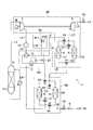
- FIG. 1 is a schematic configuration diagram illustrating a carbon dioxide recovery device according to an embodiment of the present disclosure.
- the pressure swing adsorption (PSA) method is a method that separates and removes specific components in a mixed gas by using adsorption and desorption of specific components to the adsorbent due to pressure fluctuations, and adsorbs substances capable of adsorbing carbon dioxide. It can be used as an agent to recover carbon dioxide from a gas containing carbon dioxide such as combustion exhaust gas.
- adsorption pressure By increasing the pressure of the exhaust gas supplied to the adsorbent to a relatively high pressure (adsorption pressure), carbon dioxide is adsorbed on the adsorbent and when the pressure is reduced to a relatively low pressure (desorption pressure), Carbon is desorbed and released from the adsorbent.
- the exhaust gas subjected to the drying treatment is supplied to the separation apparatus.
- a hygroscopic agent is used in the drying treatment, and the used hygroscopic agent can be regenerated and reused by heating or supplying a dry gas. Since the remaining gas after carbon dioxide is separated in the separator does not substantially contain moisture, the remaining gas can be used to regenerate the hygroscopic agent.
- the amount of residual gas after carbon dioxide separation depends on the amount of carbon dioxide contained in the exhaust gas, and the residual gas amount varies depending on the increase or decrease in the carbon dioxide content of the exhaust gas.
- the remaining gas after carbon dioxide separation is supplied as a regeneration gas for regenerating the moisture absorbent for drying.
- a carbon dioxide recovery method and a recovery apparatus configured to supply a replenishing gas from the outside as necessary to keep the supply flow rate of the regeneration gas constant are proposed.
- a carbon dioxide recovery method and a recovery apparatus that performs the carbon dioxide recovery method according to an embodiment of the present disclosure will be described with reference to the drawings.
- FIG. 1 is a schematic configuration diagram illustrating an embodiment of a carbon dioxide recovery apparatus according to the present disclosure.
- the recovery device 1 is for separating the carbon dioxide from the gas by the PSA method, the drying device DR for drying the gas supplied to the separation device SP, and the regenerating moisture absorbent H of the drying device DR.
- a regeneration system RG that supplies the remaining gas from which carbon dioxide has been removed as regeneration gas to the drying apparatus DR, and supplies replenishment gas to the remaining gas from the outside as necessary so that the flow rate of the regeneration gas becomes a predetermined amount.
- a replenishment system SU a replenishment system SU.
- the separation device SP has at least one pair of columns C1 and C2 in which the adsorbent A is accommodated. Furthermore, the compressor 3 as a pressurizing device for applying a pressure for adsorbing carbon dioxide to the adsorbent A to the gas G, and the pressure in the columns C1 and C2 to a pressure at which carbon dioxide can be desorbed from the adsorbent A. An expander 5 is provided as a decompression device for lowering. By operating the compressor 3 and the expander 5, pressure fluctuations can be generated in the columns C1 and C2, and carbon dioxide is separated from the gas G by using adsorption and desorption of carbon dioxide to the adsorbent A due to pressure fluctuations. can do.
- the carbon dioxide C concentrated to a high concentration and the remaining gas G ′ from which carbon dioxide has been removed are discharged from the separation device SP.
- the adsorption separation of carbon dioxide can be performed by a single column, but in this case, the gas G is intermittently supplied in accordance with the adsorption / desorption switching, resulting in an intermittent treatment.
- the drying device DR has a hygroscopic agent H for drying the gas G supplied to the separation device SP.
- the hygroscopic agent H is accommodated in at least one pair of columns C3 and C4.
- the gas G pressurized by the compressor 3 is dehumidified by the moisture absorbent H of the drying device DR and then supplied to the separation device SP.
- the hygroscopic agent H that has absorbed moisture can be regenerated by heating or supplying a dry gas.
- the remaining gas G ′ after the carbon dioxide is removed in the separation device SP does not substantially contain moisture. Therefore, the remaining gas G ′ can be used as a regeneration gas for regenerating the moisture absorbent H of the drying device DR, and the regeneration system RG can use the separation device SP as a regeneration gas for regenerating the moisture absorbent H of the drying device DR.
- the remaining gas G ′ discharged from the gas is supplied to the drying device DR.
- a means for heating the remaining gas G ' is provided, and the structure is devised to increase the thermal efficiency.
- the remaining gas G ′ discharged from the separation device SP is less than the gas G by the amount of carbon dioxide removed. That is, the discharge amount of the remaining gas G ′ varies according to the carbon dioxide content of the gas G supplied to the recovery device 1.
- the carbon dioxide content of the gas G is high, the flow rate of the remaining gas G ′ is significantly reduced and the regeneration gas becomes insufficient.
- the regeneration gas shortage becomes significant.
- the replenishment gas N is added from the outside to the remaining gas G ′ from the outside as necessary to maintain the amount of the regeneration gas at a predetermined amount.
- a replenishment system SU is provided.
- the replenishing gas N supplied from the outside is a gas having a moisture content that can be used for regeneration of the moisture absorbent H, and a gas that does not substantially affect the performance of the moisture absorbent is used. Therefore, a gas composed of an inert component such as nitrogen is preferably used as the supplement gas N.
- the replenishing gas N need not be a single component gas as long as it can be used for regeneration of the moisture absorbent H, and may be a mixed composition of a plurality of components.
- nitrogen gas discarded from an oxygen production apparatus (ASU) can be used as it is because it has a water content of about 1 to 2 ppm, and is useful as a supplementary gas N.
- air discharged from a facility or the like that has been subjected to air conditioning is also in a dry state and can be used as the supplement gas N.
- the replenishment system SU supplies the replenishment gas N from the outside to the remaining gas G ′ according to the flow rate of the remaining gas G ′ discharged from the separation device SP, and the regenerative gas flow rate supplied to the drying device DR is a constant amount. Maintained. Therefore, the regeneration gas is always supplied stably to the drying device DR, and the influence on the separation device SP due to the regeneration failure of the moisture absorbent H is avoided.
- the recovery apparatus 1 has a cooler 11, and the gas G containing carbon dioxide is first supplied to the cooler 11.
- the cooler 11 is a facility that cools the gas G discharged at a high temperature from a combustion facility or the like so as to have a temperature suitable for processing in a subsequent facility.
- the gas G is about 50 ° C. or less, preferably 40 ° C. It is configured to be cooled to an outlet temperature below the extent.
- the combustion exhaust gas generally has an inlet temperature of about 100 to 200 ° C., and the volume of the gas is reduced by cooling, so that the throughput in the subsequent equipment can be increased.
- the refrigerant may be any of commonly used refrigerants such as water, air, a refrigerant in a refrigeration cycle, and the like.
- the contact with the refrigerant either direct spraying such as spraying or gas-liquid contact using a filler, or cooling by an indirect contact using a condenser or a heat exchanger may be used.
- a scrubber that cools the gas G by bringing the cooling water into direct contact with the gas G is provided as the cooler 11.
- the direct contact method using cooling water has good economic efficiency and cooling efficiency, and also functions as a cleaning means for removing fine solids such as dust and acidic substances such as chlorides and sulfur oxides from the gas G. is there.
- the cooler 11 is connected to the compressor 3 by the flow path L1, and the gas G adjusted to an appropriate temperature by the cooler 11 is supplied to the compressor 3 and compressed to increase the pressure.
- the compressor 3 is operated by a power source M such as a motor, and applies a pressure required for adsorption of carbon dioxide to the gas G in the subsequent separation device SP. Specifically, a pressure is applied to the gas G such that the carbon dioxide partial pressure of the gas G supplied to the separation device SP becomes an adsorption pressure (relatively high pressure). Accordingly, the pressure applied using the compressor 3 is determined based on the carbon dioxide concentration of the gas G and the adsorption pressure.
- the pressure of the gas G depends on the carbon dioxide concentration of the gas G.
- the adsorption pressure applied in the separation device SP is preferably a pressure equal to or higher than the threshold indicated by the adsorption isotherm of the adsorbent, and varies depending on the adsorbent used.
- the adsorption pressure can be generally set to about 0.3 to 0.6 MPa.
- any pressure applying means capable of generating a fluid pressure capable of pressurizing the gas G so that the partial pressure of carbon dioxide becomes an appropriate adsorption pressure can be used.
- a method having a relatively low applied pressure as compared with the conventional method can be used, so that a compressor and a blower can be suitably used, and the compressor is optimal.
- the pressure applied to the gas G by the compressor 3 can be maintained in the separation device SP by providing a pressure control valve downstream from the separation device SP, and the pressure of the gas G is controlled by the control of the pressure control valve. Can be adjusted. In this embodiment, the pressure can be adjusted by a pressure control valve V9 (see later) provided on the regeneration gas discharge side of the drying apparatus DR.
- the temperature of the gas G rises due to pressurization by the compressor 3. For example, when a gas G having a temperature of 40 ° C. and a carbon dioxide concentration of 80% (volume ratio) is pressurized to about 0.5 MPa, the carbon dioxide partial pressure becomes about 0.4 MPa appropriate as an adsorption pressure.
- the temperature of the gas G is about 190 ° C. As described above, when the pressure of the gas G is appropriately adjusted according to the carbon dioxide concentration in the compressor 3, the temperature of the gas G after the pressure increase generally rises to about 180 to 200 ° C.
- a denitration device 13 is provided, and the compressor 3 is connected to the denitration device 13 via a flow path L2.
- the denitration device 13 is appropriately selected from denitration methods generally used for denitration of exhaust gas, such as dry denitration using a solid absorbent, adsorbent or catalyst, or wet denitration using an aqueous liquid containing a basic substance. Can be used.
- a catalyst that decomposes nitrogen oxides into nitrogen by reacting with ammonia is preferably used.
- nitrogen monoxide contained in the nitrogen oxide is extremely low in water solubility, it is difficult to dissolve and remove it with water alone.
- the oxidation of nitric oxide proceeds in the pressurized gas G to be converted into highly water-soluble nitrogen dioxide, and the water vapor in the gas G is condensed by the pressurization.
- Nitrogen oxides dissolve in condensed water as nitrogen dioxide. Accordingly, the denitration treatment of the gas G is possible by separating and removing the condensed water from the pressurized gas G using a gas-liquid separator or the like. In this processing method, a basic substance is unnecessary and the water content of the gas G is reduced, so that the burden on the subsequent drying apparatus DR is reduced.
- the denitration device 13 is connected to the heat exchanger 15 through the flow path L3, and the gas G after denitration is cooled by the remaining gas G ′ discharged from the separation device SP in the heat exchanger 15. As a result, the remaining gas G ′ is heated to a temperature suitable for use as a regeneration gas (details will be described later).
- the above-described denitration device 13 can be disposed at the rear stage of the heat exchanger 15. In that case, the amount of condensed water separated and removed by cooling the pressurized gas G increases, so that the water content of the gas G decreases and the burden of the drying process in the drying device DR is reduced.
- the heat exchanger 15 is connected to the drying device DR through the flow path L4, and the cooled gas G is subjected to a drying process by the drying device DR.
- the drying device DR is a facility that removes moisture from the gas G in order to prevent deterioration in function and damage of the adsorbent A used in the separation device SP, and the cooler 11 and the denitration device 13 in the previous stage are wet-type devices. It is particularly important when configured with.
- the drying apparatus DR has columns C3 and C4 in which a hygroscopic agent H is housed.
- the gas G is dehumidified by bringing the gas G and the hygroscopic agent H into contact with each other, and the low-humidity gas G passes through the flow path L5.
- the hygroscopic agent H may be appropriately selected from generally used hygroscopic agents such as silica gel, alumina gel, molecular sieve, zeolite, activated carbon and the like. Economically, a hygroscopic agent that can be easily regenerated by heating silica gel or the like is advantageous, and a temperature swing hygroscopic tower can be constructed.
- the drying apparatus DR using a pair of or more hygroscopic columns loaded with the hygroscopic agent H, the gas G and the high-temperature regeneration gas are alternately supplied to the hygroscopic column to absorb and absorb the gas G. The regeneration of the agent H can be performed alternately.
- the drying process and the regeneration of the hygroscopic agent H can be repeated repeatedly without stopping the process of the gas G.
- This is implemented by switching control of the switching valves V1, V2, V3, V4.
- the gas G supplied from the flow path L4 is dehumidified in one of the columns C3 and C4 by controlling the switching valves V1 and V2 so that the flow path L4 and the flow path L5 communicate with one of the columns C3 and C4. , Supplied from the flow path L5 to the separation device SP.
- the connection of the switching valves V3 and V4 is controlled so that the regeneration gas supplied to the drying apparatus DR flows through the other column and is discharged from the flow path L6.
- the switching valves V1, V2, V3, V4 may be configured to automatically switch according to the moisture concentration of the gas G discharged from the flow path L5.
- a concentration sensor is provided in the flow path L5 and is electrically connected to the switching valves V1, V2, V3, and V4, and the switching valves V1, V2, V3, and V4 are based on an increase in the moisture concentration detected by the concentration sensor. It can be configured such that the columns communicating with the flow paths L4 and L5 are changed by switching each.
- the main part of the separation device SP is constituted by columns C1 and C2 in which an adsorbent A for separating carbon dioxide from gas according to the PSA method is accommodated.
- the adsorbent A adsorbs carbon dioxide contained in the gas G, and the remaining gas G ′ from which carbon dioxide has been reduced is discharged. That is, the gas G supplied from the drying device DR to the separation device SP through the flow path L5 is carbon dioxide C that has been concentrated or purified in columns C1 and C2, and decarbonized gas from which carbon dioxide has been reduced or removed. It is separated into a residual gas G ′.
- the separation device SP is connected to the expander 5 and the liquefying device (not shown) through the flow path L7, and is connected to the drying device DR through the flow path L8.
- carbon dioxide adsorbed by the adsorbent A is desorbed by the pressure drop by the expander 5 when the column communicates with the flow path L7 by connection switching by the switching valve, and the concentrated or purified carbon dioxide C is flow path L7. , L9 to be supplied to the liquefaction device.
- the expander 5 is connected so as to cooperate with the compressor 3, and the flow pressure at the time of pressure release of the expander 5 is recovered as power and used as part of the driving force of the compressor 3. Therefore, energy consumed by the power source M of the compressor 3 can be reduced.
- a known method such as shaft connection or integral connection may be used as appropriate.
- the form which uses the scroll compressor and scroll expander which are scroll type fluid machines by a coaxial body is mentioned.
- the adsorbent A accommodated in the columns C1 and C2 is an adsorbent capable of selective adsorption of carbon dioxide by the PSA method. Since activated carbon and zeolite conventionally known as substances capable of adsorbing carbon dioxide have a negative desorption pressure, a vacuum pump is required for desorption of carbon dioxide. In contrast, in metal-organic structures that have been studied recently as adsorbents, the adsorption isotherm showing the relationship between the adsorbate pressure and the amount of equilibrium adsorption represents a sigmoid curve, with a sudden rise near a certain pressure.
- metal-organic frameworks capable of selectively adsorbing carbon dioxide are used as the adsorbent A.
- Metal-organic structures are porous materials, also called porous coordination polymers (PCPs).
- PCPs porous coordination polymers
- a metal-organic structure is based on a complex formed by coordination bonding of metal ions and organic ligands to form a porous structure skeleton. Functions as an adsorbent.
- metal-organic structures include [Cu (4,4′-dihydroxybiphenyl-3-carboxyl) 2 (4,4′-bipyridyl)] n , [Cu (PF 6 ⁇ ) 2 (1,2-bis (4-Pyridyl) ethane)] n , [Cu (CF 3 SO 3 ⁇ ) 2 (1,3-bis (4-pyridyl) propane) 2 ] n , ⁇ [Cu (PF 6 ⁇ ) (2,2- Bis (4-pyridyl))] PF 6 ⁇ ⁇ n , [Cu 2 (PF 6 ⁇ ) 2 (4,4′-bipyridyl) propane) 2 ] n , [Cu 2 (PF 6 ⁇ ) 2 (pyridine) 4 ] N , [M 2 (2,5-dioxide-1,4-benzenedicarboxylate)] (wherein M is Mg 2+ , Mn 2+ , Co 2+ , Ni 2+ ,
- a commercially available metal - Using a column with respect to the carbon dioxide from the organic structure may be properly selected to show the adsorptive pairs. In such a case, a different type of metal-organic structure may be used in each pair so that the adsorption performance corresponding to the type can be exhibited.
- -Some organic structures are adsorptive to multiple types of gases, but in such cases as well, generally the threshold pressure in the adsorption isotherm depends on the type of gas and is set to an appropriate pressure. Thus, selective adsorption of carbon dioxide can be suitably performed.
- the adsorption pressure is set to the pressure range (> 0.25 MPa) on the high pressure side with the pressure value (threshold value) at which the equilibrium adsorption amount increases rapidly, and the pressure range ( ⁇ 0.25 MPa) to the low pressure side.
- Each desorption pressure can be set.
- the desorption pressure can be set to atmospheric pressure or positive pressure (above atmospheric pressure) instead of negative pressure
- the adsorption pressure and desorption pressure can be set and adjusted by the pressure control valve without using a vacuum pump. Is possible. Therefore, the energy consumed by the vacuum pump is reduced, and the limitation on the processing capacity of the recovery device due to the performance of the vacuum pump, which is a problem in the conventional PSA method, is also eliminated.
- Separation of carbon dioxide from gas G in each column is repeated by repeating a series of operations of supplying gas G and reducing pressure so that adsorption and desorption of carbon dioxide are alternately performed between the two columns C1 and C2. And recovery are repeated alternately.
- This is implemented by switching control of the switching valves V5, V6, V7, and by controlling the switching valves V5, V6 so that the flow path L5 and the flow path L8 communicate with one of the columns C1, C2, the flow path L5.
- the gas G supplied from is adsorbed and removed by carbon dioxide in one of the columns C1 and C2, and the remaining gas G ′ is discharged from the flow path L8.
- connection of the switching valve V7 is controlled so that the other column communicates with the flow path L7 and the expander 5, the pressure in the column decreases to the desorption pressure, and carbon dioxide is released from the adsorbent A. .
- the adsorption and desorption in the columns C1 and C2 are switched by reversing the connection of the switching valves V5, V6 and V7. Therefore, carbon dioxide C is alternately collected from the pair of columns of the separation apparatus SP through the flow path L9 using the gas G continuously supplied from the compressor 3 via the drying apparatus DR.
- the recovered carbon dioxide C is finally liquefied.
- the desorption pressure in the columns C1 and C2 can be adjusted by the pressure control valve V8 in the flow path L9.
- the remaining gas G ′ from which carbon dioxide has been removed is refluxed to the drying apparatus DR through the flow path L8.
- a carbon dioxide concentration sensor is installed on the downstream side of the flow path L8, that is, the switching valve V6, the carbon dioxide concentration of the remaining gas G ′ can be detected, so that an increase in the carbon dioxide concentration due to the breach of the adsorbent A is detected. Can do. Therefore, when the concentration sensor is electrically connected to the switching valves V5, V6, and V7 and the switching valves V5, V6, and V7 are set to automatically switch based on the detected carbon dioxide concentration, the adsorbent A It is possible to switch the adsorption / desorption at a suitable timing so as to make maximum use of the adsorption capacity.
- the liquefaction of carbon dioxide C can be carried out using a compression device for compressing carbon dioxide C and a cooling device using a heat exchanger, and the liquefaction device can be configured using these.
- the concentrated or purified carbon dioxide C recovered in the separation apparatus SP is liquefied by cooling to a temperature below the boiling line temperature, preferably about ⁇ 20 to ⁇ 50 ° C. and compressing under pressure.
- the liquefied carbon dioxide C is preferably prepared in a supercritical state, and carbon dioxide C liquefied and purified to a purity of about 95 to 99% is obtained.
- the regeneration system RG that uses the remaining gas G ′ discharged from the separation apparatus SP as the regeneration gas includes a flow path L8 and a heating unit that heats the remaining gas G ′ to a high temperature. That is, the aforementioned heat exchanger 15 is arranged so as to exchange heat between the gas G in the flow path L3 and the remaining gas G 'in the flow path L8. Since the temperature of the gas G rises due to the application of pressure in the compressor 3, the remaining gas G ′ released from the separation device SP is heated by heat exchange by indirect contact with the high-temperature gas G in the heat exchanger 15. Therefore, the heat exchanger 15 cools the compressed gas G in the flow path L3, and heats the remaining gas G 'in the flow path L8 by recovering and using the heat of the gas G.
- the remaining gas G ′ acts as a heat medium that carries the heat energy of the pressurized gas G to the drying device DR.
- the hot gas G is cooled to about 50 to 70 ° C. in the heat exchanger 15 and is pumped to the drying device DR and the separation device SP.
- the cooling temperature of the gas G can be lowered to about 30 to 40 ° C. or less depending on the heat exchange rate of the heat exchanger 15.
- the remaining gas G ′ at about 20 to 40 ° C. refluxed from the separation apparatus SP is heated to about 150 to 200 ° C.
- the heat exchanger 15 may be configured using a known air-air heat exchanger.
- Any type such as a counter flow type, a parallel flow type, and a cross flow type may be used, and for example, a static heat exchanger, a rotary regenerative heat exchanger, a periodic heat storage heat exchanger, or the like can be appropriately selected. is there.
- a static heat exchanger By supplying the heated remaining gas G 'to the columns C3 and C4 as a regeneration gas, moisture is released from the used moisture absorbent H.
- the regeneration system RG further includes a heater 17 installed on the downstream side of the heat exchanger 15 and a detector installed on the downstream side of the heater 17 in order to further heat the remaining gas G ′ as necessary. 19 on the flow path L8.
- the detector 19 detects the temperature of the regeneration gas supplied to the drying device DR, and the heater 17 is electrically connected to the detector 19 so that the temperature of the remaining gas G ′ after the heat exchange is the regeneration gas. Control is performed in accordance with the detected temperature of the detector 19 so that heating is performed when the appropriate temperature is not reached.
- the regeneration gas supplied to the drying apparatus DR is a high-temperature drying gas having a temperature of about 150 to 200 ° C. and a dew point of about ⁇ 90 to ⁇ 60 ° C. that hardly contains moisture.
- the regeneration gas (remaining gas G ′) containing moisture due to the regeneration of the moisture absorbent H in the drying apparatus DR is discharged to the outside from the flow path L6 via the pressure control valve V9 and the silencer X, and the regenerated gas (remaining gas G).
- the pressure of ') is released and becomes atmospheric pressure.
- the pressure applied by the compressor 3 is maintained up to the pressure control valve V9 of the flow path L6 through the drying device DR and the separation device SP, and the pressures of the gas G and the remaining gas G 'are adjusted by the pressure control valve V9.
- the flow rate of the remaining gas G ′ discharged from the separation device SP is smaller than the flow rate of the gas G supplied to the recovery device 1 by the amount of recovered carbon dioxide C. That is, if the carbon dioxide content of the gas G is high, the remaining gas G ′, that is, the flow rate of the regeneration gas is reduced. When the flow rate of the regeneration gas decreases, the time required for regeneration of the hygroscopic agent becomes longer, so that it becomes difficult to fully utilize the hygroscopic capacity of the hygroscopic agent H.
- the recovery apparatus 1 has a replenishment system SU for replenishing from the outside the shortage of the remaining gas G ′ as regeneration gas.
- the replenishment system SU has a flow path L10 for supplying a replenishment gas N from the outside, and a flow rate adjusting valve V10 installed in the flow path L10, and the flow path L10 is connected to the flow path L8.
- the flow rate adjusting valve V10 a valve that can be electrically controlled such as an electromagnetic valve is used, and a flow meter 21 installed in the flow path L8 downstream from the connection point between the flow path L10 and the flow path L8; Electrically connected.
- the flow path L10 is a line for replenishing and supplying the external replenishment gas N to the remaining gas G ′ of the flow path L8, and the replenishment gas N has a water content that can be used for regeneration of the moisture absorbent H, preferably water.
- the amount is about 1 ppm or less.
- As the supplement gas N for example, nitrogen gas discharged from an oxygen production apparatus (ASU) is preferably used. Since the remaining gas G 'is pressurized, the supplementary gas N is supplied at a pressure equivalent to that of the remaining gas G'.
- the flow rate adjusting valve V10 is controlled according to the flow rate detected by the flow meter 21, supplies replenishing gas N when the flow rate of the regeneration gas detected by the flow meter 21 does not reach a predetermined flow rate, and is supplied to the drying device DR.
- the flow rate of the replenishing gas N is adjusted so that the flow rate of the regeneration gas is maintained at a predetermined flow rate. Therefore, the replenishing gas N is added to the remaining gas G ′ from the outside according to the flow rate of the remaining gas G ′, and the total flow rate of the remaining gas G ′ and the replenishing gas N is maintained at a constant flow rate.
- the ratio of the supply flow rate of the regeneration gas to the supply flow rate of the gas G to the hygroscopic agent H is preferably about 30% to 70%. Therefore, it is preferable to set a flow rate that satisfies the above ratio as a predetermined amount.
- the supply flow rate of the regeneration gas is maintained at a predetermined amount by adjusting the supply amount of the replenishment gas by the flow rate adjusting valve V10. As a result, the regeneration gas is always stably supplied to the drying apparatus DR, and the influence on the separation apparatus SP due to a decrease in the efficiency of the drying process and the regeneration failure of the moisture absorbent H is avoided.
- the supply adjustment of the regeneration gas may be performed based on the difference (G ⁇ G ′) between the flow rates of the gas G and the remaining gas G ′ at the entrance / exit of the separation apparatus SP.
- a detector that measures the flow rates of the gas G and the remaining gas G ′ at the inlet / outlet of the separation device SP may be provided, and the flow rate adjusting valve V10 may be controlled based on these detected values.
- the cooler 11 When the gas G supplied to the recovery device 1 has already been subjected to a water washing process or a cooling process in another facility and it is not necessary to remove unnecessary objects or cool down, the cooler 11 may be omitted. From the viewpoint of the optimum temperature in the drying apparatus DR and the separation apparatus SP, when it is necessary to enhance the cooling of the gas G, an appropriate value such as on the flow path L4 or the flow path L5 downstream of the heat exchanger 15 is used. It is preferable to add a cooler at the position, and it can be cooled to a temperature of about 20 to 30 ° C. or lower by a water-cooled cooler using a coolant of about 5 to 25 ° C. as a refrigerant.
- the number of columns in which the hygroscopic agent H is accommodated in the drying apparatus DR is appropriately changed so that a suitable drying process can be performed according to the hygroscopic rate, the hygroscopic capacity, the regeneration rate, etc. of the hygroscopic agent H used.
- the purity of the recovered carbon dioxide is increased by increasing the number of column pairs so as to increase the number of adsorption / desorption processes according to the separation selectivity of the adsorbent A. Can be improved.
- the separation performance is improved by two-stage adsorption separation. In this case, the remaining gas separated from carbon dioxide in the second stage column may be refluxed for the adsorption separation process of the first stage column.
- a concentration sensor may be provided in the flow path L9 as a detector for detecting the concentration of carbon dioxide, and this may be configured to recirculate to the flow path L5 when the concentration of recovered carbon dioxide C is low.
- low concentration carbon dioxide is supplied to the columns C1 and C2 together with the gas G, and the concentration of carbon dioxide obtained from a pair of columns can be increased.
- control valve may be automatically controlled based on the detection information while the detection information of the detector and the sensor is managed in the calculation processing device using an arithmetic processing device such as a CPU. .
- an arithmetic processing device such as a CPU.
- the carbon dioxide recovery method implemented in the recovery apparatus 1 configured as described above has a separation process, a drying process, a regeneration process, and a replenishment process as main processes.
- the separation process carbon dioxide is separated from the gas by using adsorption and desorption of carbon dioxide to the adsorbent due to pressure fluctuation, and the remaining gas from which the carbon dioxide has been removed is discharged.
- the drying process the gas supplied to the separation process is dried using a hygroscopic agent.
- the regeneration process the remaining gas discharged from the separation process is supplied to the moisture absorbent used in the drying process as a regeneration gas for regenerating the moisture absorbent.
- replenishment process replenishment gas is supplied from the outside in accordance with the flow rate of the remaining gas discharged from the separation device so that the flow rate of the regeneration gas becomes a predetermined amount. More specifically, the following operations are performed.
- the gas G to be supplied is subjected to a cooling process in a cooler and is reduced to a temperature of about 50 ° C. or lower, preferably about 40 ° C. or lower, and then the pressure at which the carbon dioxide is separated in the compressor 3.
- the pressure at which the carbon dioxide partial pressure of the gas G becomes the adsorption pressure (relatively high pressure) In general, a pressure at which the adsorption pressure is about 0.3 to 0.6 MPa is applied to the pressurization.
- the pressurized gas G rises to about 180 to 200 ° C., and is subjected to denitration treatment in the denitration device 13 and cooling by the heat exchanger 15 before being separated by the adsorbent, and is about 50 ° C.
- the temperature is preferably lowered to about 40 ° C. or lower, more preferably about 30 ° C. or lower. Thereafter, the gas G is subjected to a drying process by the drying apparatus DR, and the water content is reduced to about 1 ppm or less.
- the gas G is separated into the carbon dioxide C and the remaining gas G ′ by performing adsorption of carbon dioxide by the adsorbent A of the separation device SP on the gas G that has undergone the drying treatment (separation treatment). Since the adsorption reaction in which the metal-organic structure adsorbs carbon dioxide is an exothermic reaction, and the desorption reaction is an endothermic reaction, the temperature can fluctuate up to about 20 ° C. by repeated adsorption and desorption. Therefore, it is desirable to maintain the temperature during adsorption at a low temperature in order to adsorb carbon dioxide quickly.
- the gas G supplied to the columns C1 and C2 in the separation process is cooled in advance in the heat exchanger 15 as described above.
- the gas G is supplied as necessary.
- the cooling method of the gas G is not particularly limited as long as it is not humidified, and may be appropriately selected and applied from well-known indirect contact cooling techniques such as a water cooling type and an air cooling type, and can be satisfactorily implemented by water cooling type cooling. is there.
- a gas G having a carbon dioxide concentration of 60%, a temperature of 20 ° C., and 0.6 MPa is supplied to one of the columns C1 and C2
- adsorption of carbon dioxide is started at an adsorption pressure of 0.36 MPa.
- the gas released from this column is discharged through the flow path L8 as the remaining gas G '.
- the carbon dioxide concentration of the remaining gas is extremely low until the amount of carbon dioxide adsorbed approaches the adsorption capacity of the adsorbent A, but when the adsorbent A breaks down (adsorption saturation), the remaining gas G decreases due to a decrease in the adsorption rate. 'The carbon dioxide concentration begins to increase.
- the carbon dioxide concentration of the remaining gas G ′ reaches 60% of the original concentration.
- the carbon dioxide adsorbed by the adsorbent A is released by reducing the desorption pressure.
- the pressure is regulated to a desorption pressure of about 0.2 MPa by the pressure control valve V8, and the concentration of carbon dioxide discharged from the column to the flow path L7 increases from 60% due to the desorption of carbon dioxide from the adsorbent A, and is concentrated.
- the carbon dioxide C thus collected is recovered from the flow path L9.
- the temperature of the adsorbent A is lowered by an endothermic reaction at the time of desorption, the temperature inside the adsorbent A at the time of adsorption becomes higher than that at the time of desorption even if the supplied gas G is cooled to a constant temperature.
- the speed at which the adsorbent A takes in carbon dioxide at the time of adsorption is faster than the speed at which it is released at the time of desorption, and can generally be about 1.2 times. Accordingly, the carbon dioxide emission from the desorption side adsorbent A is substantially continued until the adsorption side adsorbent A is broken.
- the carbon dioxide concentration of the gas released from the adsorbent by desorption increases from the carbon dioxide concentration of the gas G and can reach a purity of 95% (volume ratio) or more.
- the concentration of carbon dioxide in the gas G is about 60% or more, it is possible to recover the carbon dioxide C concentrated or purified to a concentration of 90 to 99%.
- the carbon dioxide C may be collected when the concentration of the desorbed carbon dioxide C becomes a predetermined concentration or more. The recovered carbon dioxide is subjected to liquefaction treatment as necessary.
- the remaining gas G ′ separated and discharged in the separation process is used in the regeneration process as a regeneration gas for the dehumidifying agent used in the drying process.
- a replenishment process for supplying the replenishment gas N from the outside according to the flow rate of the remaining gas G ′ is performed so that the flow rate of the regeneration gas in the regeneration process is maintained at a predetermined amount. Accordingly, a regeneration gas in which the supplement gas N is appropriately added to the remaining gas G ′ is prepared.
- This is heated to a temperature of about 150 to 200 ° C. by heat exchange with the pressurized gas G before the drying process, and becomes a high-temperature dry gas having a dew point of about ⁇ 90 to ⁇ 60 ° C. containing almost no moisture.
- the regeneration process of the moisture absorbent H used in the drying process is performed. Therefore, the amount of heat of the pressurized gas G is recovered and utilized as regeneration heat of the dehumidifying agent, so the configuration of the present disclosure is excellent in terms of energy utilization efficiency.
- the regeneration gas containing moisture by the regeneration process is discharged to the outside.
- the composition of the combustion exhaust gas varies depending on the fuel and combustion type, and the exhaust gas by oxyfuel combustion generally contains about 80% carbon dioxide, about 10% nitrogen and about 10% oxygen (volume ratio). A small amount of water vapor and impurities such as sulfur oxide, nitrogen oxide, chlorine, mercury and the like may be included.
- carbon dioxide concentrated at a high concentration of about 98% or more can be recovered from the separation device SP including the metal-organic structure as an adsorbent. Since the gas G supplied to the separation apparatus SP has the water vapor and nitrogen oxides removed through the denitration apparatus 13 and the drying apparatus DR, the remaining gas G ′ discharged from the separation apparatus SP contains almost no water vapor. It is suitable for use as a regeneration gas in the drying apparatus DR.
- the technology of the present disclosure may be applied to a carbon dioxide-containing gas other than exhaust gas. Moreover, you may utilize for the refinement
- the carbon dioxide concentration of the gas G is low, it can be dealt with by increasing the pressure applied in the compressor 3 so that the carbon dioxide partial pressure of the gas G becomes a suitable adsorption pressure.
- the pressure of the gas G is increased, the partial pressure of other components (nitrogen, oxygen, etc.) contained in the gas G is also increased, so that the adsorption of other components may proceed.
- the pressure of the gas G is set within a range where the equilibrium adsorption amount of the other component in the partial pressure of the other component becomes small.
- the configuration of the separation device SP and the separation process can be changed as appropriate according to the situation. For example, carbon dioxide having a concentration lower than a predetermined concentration released from the desorption side may be temporarily collected in a storage container and separately separated. If the metal-organic structure used has a relatively low selective adsorptivity to carbon dioxide, as described above, the separation process using a pair of columns is configured in multiple stages to concentrate or purify carbon dioxide. The purity can be increased. Further, a plurality of pairs of columns may be arranged in parallel to increase the gas processing capacity.
- the separation device SP can also make a change related to fluctuations in the internal temperature of the adsorbent A due to adsorption and desorption.
- a pipe for indirect heat exchange can be arranged inside the adsorbent A in the column so that the heat medium flows through the pipe, or a heat storage material can be arranged in the adsorbent A.
- the pipe inside the adsorbent A it is also possible to provide a jacket that covers the outer periphery of the adsorption tower and change the heating medium to flow through the jacket and to be heated or cooled from the outside.
- the separation apparatus SP configured as described above can cope with a rapid temperature fluctuation. For example, when applied to the purification of a relatively high concentration of carbon dioxide, the adsorbent A is generated by vigorous heat generation during adsorption. Temperature rise can be suppressed from the inside.
- an adsorbent that exhibits selective adsorptivity to nitrogen in advance for example, a crystalline hydrous aluminosilicate alkaline earth
- the pre-processing which raises the carbon dioxide concentration in gas by the adsorption process using metal salt (zeolite) etc. may be performed.
- the nitrogen adsorbed in the pretreatment it can be used as the replenishing gas N from the outside and used for the regeneration of the moisture absorbent H.
- carbon dioxide contained in a mixed gas such as combustion exhaust gas and process exhaust gas is adsorbed and separated by the PSA method to efficiently produce carbon dioxide concentrated or purified to a high concentration, and the apparatus configuration includes a vacuum pump or the like
- An economically advantageous carbon dioxide recovery technique that does not require means for generating the negative pressure is provided.
- the nitrogen gas discharged from other facilities is used effectively, so it is useful as a comprehensive exhaust gas treatment in thermal power plants, steel plants, boilers and other combustion facilities. It is a new carbon dioxide-containing gas processing technology, and can contribute to the construction of energy supply technology considering energy saving and environmental protection.
Landscapes
- Chemical & Material Sciences (AREA)
- Chemical Kinetics & Catalysis (AREA)
- Analytical Chemistry (AREA)
- Engineering & Computer Science (AREA)
- Organic Chemistry (AREA)
- General Chemical & Material Sciences (AREA)
- Oil, Petroleum & Natural Gas (AREA)
- Inorganic Chemistry (AREA)
- Environmental & Geological Engineering (AREA)
- Health & Medical Sciences (AREA)
- Biomedical Technology (AREA)
- Thermal Sciences (AREA)
- Physics & Mathematics (AREA)
- Materials Engineering (AREA)
- Life Sciences & Earth Sciences (AREA)
- Sustainable Development (AREA)
- Drying Of Gases (AREA)
- Separation Of Gases By Adsorption (AREA)
- Carbon And Carbon Compounds (AREA)
- Treating Waste Gases (AREA)
Abstract
Description
Claims (10)
- 圧力変動による二酸化炭素の吸着剤に対する吸着及び脱着を利用してガスから二酸化炭素を分離し、二酸化炭素が除去された残部ガスを排出する分離装置と、
前記分離装置へ供給されるガスを乾燥するための吸湿剤を有する乾燥装置と、
前記分離装置から排出される残部ガスを、前記乾燥装置の吸湿剤を再生するための再生ガスとして前記乾燥装置に供給する再生システムと、
前記再生ガスの流量が所定量になるように、前記分離装置から排出される前記残部ガスの流量に応じて外部から補充ガスを前記残部ガスに供給する補充システムと
を有する二酸化炭素の回収装置。 - 前記補充システムは、酸素製造装置から廃棄される窒素ガスを前記補充ガスとして供給するラインを有し、前記分離装置の吸着剤は、金属-有機構造体を有する請求項1に記載の二酸化炭素の回収装置。
- 前記補充システムは、
前記乾燥装置に供給される再生ガスの流量を測定する流量計と、
前記流量計と電気的に接続され、前記補充ガスの供給を調整するための流量調整弁と
を有する請求項1又は2に記載の二酸化炭素の回収装置。 - 前記分離装置は、前記吸着剤が二酸化炭素を吸着可能な圧力になるように、前記分離装置へ供給されるガスを加圧する加圧装置を有し、
前記補充システムは、更に、前記加圧装置によって加圧されたガスと前記乾燥装置へ供給される再生ガスとを熱交換する熱交換器を有し、
前記熱交換器における熱交換によって、前記残部ガスが加熱されると共に、前記加圧されたガスが冷却されて前記乾燥装置及び前記分離装置へ供給される請求項1~3の何れか一項に記載の二酸化炭素の回収装置。 - 前記熱交換器が熱交換する再生ガスは、前記補充ガスが供給された前記残部ガスである請求項4に記載の二酸化炭素の回収装置。
- 前記分離装置は、前記吸着剤を収容する対になったカラムと、前記吸着剤に吸着された二酸化炭素が脱着可能な圧力に前記カラム内の圧力を低下させる減圧装置とを有する請求項4又は5に記載の二酸化炭素の回収装置。
- 前記加圧装置は、ガスを圧縮する圧縮機を有し、前記減圧装置は、前記圧縮機と協働するように構成される膨張機を有する請求項6に記載の二酸化炭素の回収装置。
- 更に、前記分離装置へ供給されるガスから窒素酸化物を除去するための脱硝装置を有する請求項1~7の何れか一項に記載の二酸化炭素の回収装置。
- 前記脱硝装置は、ガスから凝縮する凝縮水を分離する気液分離器を有し、これにより前記凝縮水に含まれる窒素酸化物を除去する請求項8に記載の二酸化炭素の回収装置。
- 圧力変動による二酸化炭素の吸着剤に対する吸着及び脱着を利用してガスから二酸化炭素を分離し、二酸化炭素が除去された残部ガスを排出する分離処理と、
前記分離処理へ供給されるガスを、吸湿剤を用いて乾燥する乾燥処理と、
前記分離処理から排出される残部ガスを、吸湿剤を再生する再生ガスとして前記乾燥処理で用いた前記吸湿剤に供給する再生処理と、
前記再生ガスの流量が所定量になるように、前記分離処理から排出される前記残部ガスの流量に応じて外部から補充ガスを供給する補充処理と
を有する二酸化炭素の回収方法。
Priority Applications (3)
| Application Number | Priority Date | Filing Date | Title |
|---|---|---|---|
| AU2017234497A AU2017234497B2 (en) | 2016-03-16 | 2017-01-13 | Carbon dioxide recovery method and recovery device |
| CA3017323A CA3017323C (en) | 2016-03-16 | 2017-01-13 | Carbon dioxide recovery method and recovery device |
| US15/960,745 US10682603B2 (en) | 2016-03-16 | 2018-04-24 | Carbon dioxide recovery method and recovery device |
Applications Claiming Priority (2)
| Application Number | Priority Date | Filing Date | Title |
|---|---|---|---|
| JP2016051910A JP6743433B2 (ja) | 2016-03-16 | 2016-03-16 | 二酸化炭素の回収方法及び回収装置 |
| JP2016-051910 | 2016-03-16 |
Related Child Applications (1)
| Application Number | Title | Priority Date | Filing Date |
|---|---|---|---|
| US15/960,745 Continuation US10682603B2 (en) | 2016-03-16 | 2018-04-24 | Carbon dioxide recovery method and recovery device |
Publications (1)
| Publication Number | Publication Date |
|---|---|
| WO2017159017A1 true WO2017159017A1 (ja) | 2017-09-21 |
Family
ID=59850244
Family Applications (1)
| Application Number | Title | Priority Date | Filing Date |
|---|---|---|---|
| PCT/JP2017/000945 Ceased WO2017159017A1 (ja) | 2016-03-16 | 2017-01-13 | 二酸化炭素の回収方法及び回収装置 |
Country Status (5)
| Country | Link |
|---|---|
| US (1) | US10682603B2 (ja) |
| JP (1) | JP6743433B2 (ja) |
| AU (1) | AU2017234497B2 (ja) |
| CA (1) | CA3017323C (ja) |
| WO (1) | WO2017159017A1 (ja) |
Cited By (1)
| Publication number | Priority date | Publication date | Assignee | Title |
|---|---|---|---|---|
| JP2018115828A (ja) * | 2017-01-20 | 2018-07-26 | 株式会社Ihi | 二酸化炭素の回収方法及び回収装置 |
Families Citing this family (25)
| Publication number | Priority date | Publication date | Assignee | Title |
|---|---|---|---|---|
| JP6790403B2 (ja) * | 2016-03-25 | 2020-11-25 | 株式会社Ihi | 二酸化炭素の回収方法及び回収装置 |
| CN107857270A (zh) * | 2017-12-15 | 2018-03-30 | 中石化南京工程有限公司 | 一种硅粉干燥及氮气回收装置 |
| US10695710B2 (en) * | 2018-08-02 | 2020-06-30 | Messer Industries Usa, Inc. | Methods for producing ozone and oxygen mixtures |
| CN108917244A (zh) * | 2018-09-10 | 2018-11-30 | 天津渤海石化有限公司 | 丙烯回收装置及丙烯回收方法 |
| US11772039B2 (en) | 2018-09-25 | 2023-10-03 | Sekisui Chemical Co., Ltd. | Gas treatment method and gas treatment apparatus |
| JP7644500B2 (ja) * | 2019-04-29 | 2025-03-12 | カーボンクエスト, インコーポレイテッド | 建物排出物処理および/または隔離システムならびに方法 |
| WO2020242863A1 (en) | 2019-05-24 | 2020-12-03 | Entegris, Inc. | Methods and systems for adsorbing organometallic vapor |
| JP7199537B2 (ja) * | 2019-06-19 | 2023-01-05 | 日揮グローバル株式会社 | 天然ガス前処理システム及び天然ガスの前処理方法 |
| IT201900013281A1 (it) * | 2019-07-30 | 2021-01-30 | Leonardo Spa | Procedimento per l’ottenimento di anidride carbonica dai fumi di combustione delle caldaie |
| CN110743313A (zh) * | 2019-10-29 | 2020-02-04 | 中国华能集团有限公司 | 一种烟气低温吸附脱硝方法 |
| JP7443723B2 (ja) * | 2019-11-06 | 2024-03-06 | 株式会社豊田中央研究所 | 二酸化炭素回収装置、炭化水素生成装置、炭素循環システム、および、二酸化炭素回収方法 |
| CL2020001865A1 (es) * | 2020-07-14 | 2020-09-04 | Inst De Transferencia Tecnologica Y Emprendimiento Ltda | Sistema para la captura y purificación de co2 y unidad de purificación de dicho sistema |
| WO2022014652A1 (ja) * | 2020-07-15 | 2022-01-20 | 日東電工株式会社 | 調湿システム、吸脱着装置、調湿装置及び調湿方法 |
| EP4251304A4 (en) * | 2020-11-29 | 2024-11-27 | Terrafixing Inc. | DIRECT AIR CAPTURE AND CONCENTRATION OF CO2 USING ADSORPTION AGENTS |
| GB2603936B (en) * | 2021-02-19 | 2025-05-07 | Highview Entpr Ltd | Method and apparatus for drying a process gas |
| JP7728191B2 (ja) * | 2021-08-26 | 2025-08-22 | 株式会社東芝 | 二酸化炭素吸収放出デバイス |
| CN113750758B (zh) * | 2021-09-30 | 2024-03-08 | 广州市浩立生物科技有限公司 | 一种回收烟气中二氧化碳的方法 |
| GB202206101D0 (en) | 2022-04-27 | 2022-06-08 | Mof Tech Limited | Method and apparatus for carbon dioxide separation |
| GB202316731D0 (en) | 2023-11-01 | 2023-12-13 | Mof Tech Limited | Method and apparatus for carbon dioxide serparation |
| GB2623052A (en) * | 2022-09-15 | 2024-04-10 | Carbon Capture Tech Limited | Carbon removal system |
| JP7577716B2 (ja) * | 2022-09-28 | 2024-11-05 | 本田技研工業株式会社 | 二酸化炭素除去装置、二酸化炭素脱離判定方法、及び二酸化炭素分離方法 |
| JP7749195B2 (ja) * | 2023-04-14 | 2025-10-06 | 岩谷産業株式会社 | 二酸化炭素回収システムおよび二酸化炭素の回収方法 |
| US20250032973A1 (en) * | 2023-07-26 | 2025-01-30 | Mitsubishi Heavy Industries, Ltd. | Co2 recovery device |
| CN116780783B (zh) * | 2023-08-16 | 2024-01-26 | 势加透博(河南)能源科技有限公司 | 二氧化碳捕集储能系统及控制方法 |
| JP2026006166A (ja) * | 2024-06-28 | 2026-01-16 | 株式会社小松製作所 | 排ガス処理装置及び排ガス処理方法 |
Citations (4)
| Publication number | Priority date | Publication date | Assignee | Title |
|---|---|---|---|---|
| JP2011067792A (ja) * | 2009-09-28 | 2011-04-07 | Energy Products Co Ltd | 分離回収システム |
| JP2011529848A (ja) * | 2008-07-29 | 2011-12-15 | プラクスエア・テクノロジー・インコーポレイテッド | 燃焼排ガスからの二酸化炭素の回収 |
| JP2012110824A (ja) * | 2010-11-24 | 2012-06-14 | Osaka Gas Co Ltd | Psa装置 |
| JP2016040025A (ja) * | 2014-08-12 | 2016-03-24 | 株式会社Ihi | 二酸化炭素の回収方法及び回収装置 |
Family Cites Families (11)
| Publication number | Priority date | Publication date | Assignee | Title |
|---|---|---|---|---|
| US3221477A (en) * | 1961-04-24 | 1965-12-07 | United Aircraft Corp | Space adsorption system and method |
| JPS5350376Y2 (ja) | 1973-03-07 | 1978-12-02 | ||
| US4784672A (en) * | 1987-10-08 | 1988-11-15 | Air Products And Chemicals, Inc. | Regeneration of adsorbents |
| US5846295A (en) * | 1997-03-07 | 1998-12-08 | Air Products And Chemicals, Inc. | Temperature swing adsorption |
| JP2001221429A (ja) | 2000-02-09 | 2001-08-17 | Nippon Sanso Corp | 酸素燃焼設備への酸素供給装置及び供給方法 |
| US7575624B2 (en) * | 2006-12-19 | 2009-08-18 | Uop Pllc | Molecular sieve and membrane system to purify natural gas |
| FR2918579B1 (fr) | 2007-07-13 | 2010-01-01 | Air Liquide | Procede de purification d'un gaz contenant du co2 par integration d'unite de purification par adsorption |
| US8591627B2 (en) * | 2009-04-07 | 2013-11-26 | Innosepra Llc | Carbon dioxide recovery |
| JP2010184229A (ja) | 2009-01-19 | 2010-08-26 | Hitachi Ltd | 二酸化炭素吸着材及びこれを用いた二酸化炭素回収装置 |
| JP6790403B2 (ja) * | 2016-03-25 | 2020-11-25 | 株式会社Ihi | 二酸化炭素の回収方法及び回収装置 |
| JP6834515B2 (ja) * | 2017-01-20 | 2021-02-24 | 株式会社Ihi | 二酸化炭素の回収方法及び回収装置 |
-
2016
- 2016-03-16 JP JP2016051910A patent/JP6743433B2/ja active Active
-
2017
- 2017-01-13 WO PCT/JP2017/000945 patent/WO2017159017A1/ja not_active Ceased
- 2017-01-13 AU AU2017234497A patent/AU2017234497B2/en active Active
- 2017-01-13 CA CA3017323A patent/CA3017323C/en active Active
-
2018
- 2018-04-24 US US15/960,745 patent/US10682603B2/en active Active
Patent Citations (4)
| Publication number | Priority date | Publication date | Assignee | Title |
|---|---|---|---|---|
| JP2011529848A (ja) * | 2008-07-29 | 2011-12-15 | プラクスエア・テクノロジー・インコーポレイテッド | 燃焼排ガスからの二酸化炭素の回収 |
| JP2011067792A (ja) * | 2009-09-28 | 2011-04-07 | Energy Products Co Ltd | 分離回収システム |
| JP2012110824A (ja) * | 2010-11-24 | 2012-06-14 | Osaka Gas Co Ltd | Psa装置 |
| JP2016040025A (ja) * | 2014-08-12 | 2016-03-24 | 株式会社Ihi | 二酸化炭素の回収方法及び回収装置 |
Cited By (2)
| Publication number | Priority date | Publication date | Assignee | Title |
|---|---|---|---|---|
| JP2018115828A (ja) * | 2017-01-20 | 2018-07-26 | 株式会社Ihi | 二酸化炭素の回収方法及び回収装置 |
| WO2018135206A1 (ja) * | 2017-01-20 | 2018-07-26 | 株式会社Ihi | 二酸化炭素の回収方法及び回収装置 |
Also Published As
| Publication number | Publication date |
|---|---|
| JP6743433B2 (ja) | 2020-08-19 |
| US20180236395A1 (en) | 2018-08-23 |
| AU2017234497A1 (en) | 2018-05-17 |
| CA3017323C (en) | 2020-07-28 |
| AU2017234497B2 (en) | 2019-06-27 |
| JP2017164683A (ja) | 2017-09-21 |
| CA3017323A1 (en) | 2017-09-21 |
| US10682603B2 (en) | 2020-06-16 |
Similar Documents
| Publication | Publication Date | Title |
|---|---|---|
| JP6743433B2 (ja) | 二酸化炭素の回収方法及び回収装置 | |
| JP6790403B2 (ja) | 二酸化炭素の回収方法及び回収装置 | |
| JP6575050B2 (ja) | 二酸化炭素の回収方法及び回収装置 | |
| JP6834515B2 (ja) | 二酸化炭素の回収方法及び回収装置 | |
| JP6728875B2 (ja) | 二酸化炭素の回収装置及び天然ガスの燃焼システム | |
| JP6070851B2 (ja) | 排ガスの処理システム及び処理方法 | |
| CA3230475A1 (en) | A temperature vacuum swing adsorption process suited for carbon capture to regenerate sorbents using the co2 product gas as the heat transfer medium | |
| JP2012503543A (ja) | Noxとso2吸着剤/触媒として活性炭を用いる二酸化炭素精製 | |
| JP2012503593A (ja) | 二酸化炭素を精製し硫酸と硝酸を製造する多段方法 | |
| TW201841683A (zh) | 二氧化碳去除裝置、及吸附劑的二氧化碳吸附容量的回復方法 | |
| JPH07108368B2 (ja) | 混合ガス中の水分除去方法 | |
| JP3084248B2 (ja) | 燃焼排ガスから二酸化炭素を回収するための2段式吸着分離設備および2段式二酸化炭素吸着分離方法 | |
| CN101626831A (zh) | 一氧化碳吸附剂、气体纯化方法及气体纯化装置 | |
| JPH03135410A (ja) | 揮発性有機物の圧力スイング式分離回収方法 | |
| JP3544860B2 (ja) | 空気分離装置における前処理装置 | |
| JPH09122432A (ja) | 圧力スイング吸着法によるガス分離装置 | |
| JP2013017930A (ja) | 吸着剤を利用した水分除去、冷熱の回収を行う、低温液化voc回収方法におけるvoc回収率の向上方法 | |
| JP2004209474A (ja) | 空気分離装置における前処理方法およびそれに用いる装置 | |
| JP3515901B2 (ja) | 空気分離装置における前処理装置 | |
| CN121463987A (zh) | 气体处理系统和方法 | |
| NO348786B1 (en) | Method and system for direct air capture of CO2 utilizing a physical adsorbent | |
| JPS60231401A (ja) | Ca−Νa−A,Νa−X−ΝaClを使つたΝ↓2吸着塔による酸素製造方法 |
Legal Events
| Date | Code | Title | Description |
|---|---|---|---|
| ENP | Entry into the national phase |
Ref document number: 2017234497 Country of ref document: AU Date of ref document: 20170113 Kind code of ref document: A |
|
| ENP | Entry into the national phase |
Ref document number: 3017323 Country of ref document: CA |
|
| NENP | Non-entry into the national phase |
Ref country code: DE |
|
| 121 | Ep: the epo has been informed by wipo that ep was designated in this application |
Ref document number: 17766025 Country of ref document: EP Kind code of ref document: A1 |
|
| 122 | Ep: pct application non-entry in european phase |
Ref document number: 17766025 Country of ref document: EP Kind code of ref document: A1 |