WO2017154954A1 - 回路構成体 - Google Patents
回路構成体 Download PDFInfo
- Publication number
- WO2017154954A1 WO2017154954A1 PCT/JP2017/009159 JP2017009159W WO2017154954A1 WO 2017154954 A1 WO2017154954 A1 WO 2017154954A1 JP 2017009159 W JP2017009159 W JP 2017009159W WO 2017154954 A1 WO2017154954 A1 WO 2017154954A1
- Authority
- WO
- WIPO (PCT)
- Prior art keywords
- fixing member
- heat sink
- circuit structure
- thermal expansion
- leg
- Prior art date
- Legal status (The legal status is an assumption and is not a legal conclusion. Google has not performed a legal analysis and makes no representation as to the accuracy of the status listed.)
- Ceased
Links
Images




Classifications
-
- H—ELECTRICITY
- H01—ELECTRIC ELEMENTS
- H01F—MAGNETS; INDUCTANCES; TRANSFORMERS; SELECTION OF MATERIALS FOR THEIR MAGNETIC PROPERTIES
- H01F27/00—Details of transformers or inductances, in general
- H01F27/08—Cooling; Ventilating
- H01F27/22—Cooling by heat conduction through solid or powdered fillings
-
- H—ELECTRICITY
- H01—ELECTRIC ELEMENTS
- H01F—MAGNETS; INDUCTANCES; TRANSFORMERS; SELECTION OF MATERIALS FOR THEIR MAGNETIC PROPERTIES
- H01F27/00—Details of transformers or inductances, in general
- H01F27/08—Cooling; Ventilating
-
- H—ELECTRICITY
- H01—ELECTRIC ELEMENTS
- H01F—MAGNETS; INDUCTANCES; TRANSFORMERS; SELECTION OF MATERIALS FOR THEIR MAGNETIC PROPERTIES
- H01F17/00—Fixed inductances of the signal type
- H01F17/04—Fixed inductances of the signal type with magnetic core
- H01F17/045—Fixed inductances of the signal type with magnetic core with core of cylindric geometry and coil wound along its longitudinal axis, i.e. rod or drum core
-
- H—ELECTRICITY
- H01—ELECTRIC ELEMENTS
- H01F—MAGNETS; INDUCTANCES; TRANSFORMERS; SELECTION OF MATERIALS FOR THEIR MAGNETIC PROPERTIES
- H01F27/00—Details of transformers or inductances, in general
- H01F27/02—Casings
-
- H—ELECTRICITY
- H01—ELECTRIC ELEMENTS
- H01F—MAGNETS; INDUCTANCES; TRANSFORMERS; SELECTION OF MATERIALS FOR THEIR MAGNETIC PROPERTIES
- H01F27/00—Details of transformers or inductances, in general
- H01F27/02—Casings
- H01F27/022—Encapsulation
-
- H—ELECTRICITY
- H01—ELECTRIC ELEMENTS
- H01F—MAGNETS; INDUCTANCES; TRANSFORMERS; SELECTION OF MATERIALS FOR THEIR MAGNETIC PROPERTIES
- H01F27/00—Details of transformers or inductances, in general
- H01F27/06—Mounting, supporting, or suspending transformers, reactors, or choke coils not being of the signal type
-
- H—ELECTRICITY
- H01—ELECTRIC ELEMENTS
- H01F—MAGNETS; INDUCTANCES; TRANSFORMERS; SELECTION OF MATERIALS FOR THEIR MAGNETIC PROPERTIES
- H01F27/00—Details of transformers or inductances, in general
- H01F27/24—Magnetic cores
- H01F27/26—Fastening parts of the core together; Fastening or mounting the core on casing or support
- H01F27/266—Fastening or mounting the core on casing or support
-
- H—ELECTRICITY
- H01—ELECTRIC ELEMENTS
- H01F—MAGNETS; INDUCTANCES; TRANSFORMERS; SELECTION OF MATERIALS FOR THEIR MAGNETIC PROPERTIES
- H01F27/00—Details of transformers or inductances, in general
- H01F27/28—Coils; Windings; Conductive connections
- H01F27/2823—Wires
-
- H—ELECTRICITY
- H01—ELECTRIC ELEMENTS
- H01F—MAGNETS; INDUCTANCES; TRANSFORMERS; SELECTION OF MATERIALS FOR THEIR MAGNETIC PROPERTIES
- H01F27/00—Details of transformers or inductances, in general
- H01F27/28—Coils; Windings; Conductive connections
- H01F27/30—Fastening or clamping coils, windings, or parts thereof together; Fastening or mounting coils or windings on core, casing, or other support
- H01F27/306—Fastening or mounting coils or windings on core, casing or other support
-
- H—ELECTRICITY
- H05—ELECTRIC TECHNIQUES NOT OTHERWISE PROVIDED FOR
- H05K—PRINTED CIRCUITS; CASINGS OR CONSTRUCTIONAL DETAILS OF ELECTRIC APPARATUS; MANUFACTURE OF ASSEMBLAGES OF ELECTRICAL COMPONENTS
- H05K1/00—Printed circuits
- H05K1/02—Details
- H05K1/0201—Thermal arrangements, e.g. for cooling, heating or preventing overheating
- H05K1/0203—Cooling of mounted components
- H05K1/021—Components thermally connected to metal substrates or heat-sinks by insert mounting
-
- H—ELECTRICITY
- H05—ELECTRIC TECHNIQUES NOT OTHERWISE PROVIDED FOR
- H05K—PRINTED CIRCUITS; CASINGS OR CONSTRUCTIONAL DETAILS OF ELECTRIC APPARATUS; MANUFACTURE OF ASSEMBLAGES OF ELECTRICAL COMPONENTS
- H05K3/00—Apparatus or processes for manufacturing printed circuits
- H05K3/30—Assembling printed circuits with electric components, e.g. with resistors
- H05K3/32—Assembling printed circuits with electric components, e.g. with resistors electrically connecting electric components or wires to printed circuits
- H05K3/321—Assembling printed circuits with electric components, e.g. with resistors electrically connecting electric components or wires to printed circuits by conductive adhesives
-
- H—ELECTRICITY
- H01—ELECTRIC ELEMENTS
- H01F—MAGNETS; INDUCTANCES; TRANSFORMERS; SELECTION OF MATERIALS FOR THEIR MAGNETIC PROPERTIES
- H01F17/00—Fixed inductances of the signal type
- H01F17/04—Fixed inductances of the signal type with magnetic core
- H01F17/045—Fixed inductances of the signal type with magnetic core with core of cylindric geometry and coil wound along its longitudinal axis, i.e. rod or drum core
- H01F2017/046—Fixed inductances of the signal type with magnetic core with core of cylindric geometry and coil wound along its longitudinal axis, i.e. rod or drum core helical coil made of flat wire, e.g. with smaller extension of wire cross section in the direction of the longitudinal axis
-
- H—ELECTRICITY
- H05—ELECTRIC TECHNIQUES NOT OTHERWISE PROVIDED FOR
- H05K—PRINTED CIRCUITS; CASINGS OR CONSTRUCTIONAL DETAILS OF ELECTRIC APPARATUS; MANUFACTURE OF ASSEMBLAGES OF ELECTRICAL COMPONENTS
- H05K2201/00—Indexing scheme relating to printed circuits covered by H05K1/00
- H05K2201/10—Details of components or other objects attached to or integrated in a printed circuit board
- H05K2201/10007—Types of components
- H05K2201/1003—Non-printed inductor
Definitions
- the technique disclosed in this specification relates to a circuit structure.
- a structure described in Japanese Patent Application Laid-Open No. 2004-253508 is known as a structure for fixing an inductor to a fixing member.
- a fixing hole is formed in a circuit board as a fixing member, and a fixing hole is also formed in the inductor.
- Bolts are formed in the fixing member hole and the inductor hole.
- the inductor directly bond the inductor to the fixing member via an adhesive.
- the coefficient of thermal expansion of the component that constitutes the inductor is different from the coefficient of thermal expansion of the material that constitutes the fixing member, the inductor and the fixing member , Stress based on the difference in thermal expansion coefficient is applied to either one of them. Then, there is a concern that problems such as deformation of the inductor component or the fixing member may occur.
- the core constituting the inductor has a relatively small coefficient of thermal expansion, which is easily affected by stress due to heating.
- the technology disclosed in this specification has been completed based on the above-described circumstances, and aims to suppress stress applied to the core when the circuit structure is heated.
- the technology disclosed in the present specification is a circuit configuration body including an inductor having a core and a fixing member to which the inductor is fixed, and includes a base portion attached to the core, and the fixing member Is made of a first material having a thermal expansion coefficient larger than the thermal expansion coefficient of the core, and the base portion has a heat larger than the thermal expansion coefficient of the core and smaller than the thermal expansion coefficient of the fixing member. It consists of the 2nd material which has an expansion coefficient, and is distribute
- the difference between the thermal expansion coefficient of the fixing member and the thermal expansion coefficient of the core can be absorbed by the base. Therefore, when a circuit structure is heated, the stress added to a core can be suppressed.
- the inductor is housed in a case, and the bottom wall of the case is the pedestal.
- the number of parts can be reduced as compared with the case where the base portion and the case are formed as separate members.
- the base has a leg protruding toward the fixing member, and the adhesive layer is formed in a gap formed between the base and the fixing member by the leg. Is preferred.
- the dimension of the gap between the base part and the fixing member can be defined by the projecting dimension of the leg part from the base part.
- the leg portion has a plurality of leg portions, and at least one of the plurality of leg portions is a positioning leg portion that is set to have a larger projecting dimension from the bottom surface of the base portion than the other leg portions.
- the fixing member preferably has a positioning hole through which the positioning leg portion is inserted at a position corresponding to the positioning leg portion.
- the inductor can be easily positioned on the fixed member by inserting the positioning leg portion into the positioning hole. Thereby, the manufacturing efficiency of a circuit structure can be improved.
- the adhesive layer may be made of a thermosetting adhesive.
- thermosetting adhesive In order to cure the thermosetting adhesive, it is necessary to heat the circuit structure.
- the technique disclosed in this specification can be suitably used in such a case.
- the fixing member may be a metal heat sink.
- the heat generated in the circuit structure can be efficiently transferred to the heat sink and dissipated to the outside, so that the heat dissipation of the circuit structure can be improved.
- the fixing member to which the inductor is fixed is a metal heat sink
- the metal since the metal has a larger thermal expansion coefficient than the core, the difference between the expansion coefficient of the core due to heating and the expansion coefficient of the heat sink tends to increase. In such a case, the stress applied to the core from the heat sink can be effectively suppressed by applying the technique disclosed in this specification.
- the fixing member may be a glass epoxy substrate.
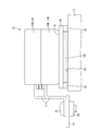
- FIG. 3 is a partially cutaway side view showing the circuit structure according to the first embodiment.
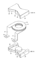
- Perspective view showing coil device An exploded perspective view showing a coil and a core
- a side view showing a circuit composition object concerning modification 1 A side view showing a circuit composition object concerning modification 2.
- Embodiment 1 of the technique disclosed in this specification will be described with reference to FIGS. 1 to 3.
- the circuit configuration body 10 according to the present embodiment is mounted on a vehicle such as an electric vehicle or a hybrid vehicle and used as a DC / DC converter.
- the X direction is right
- the Y direction is front
- the Z direction is upward.
- the circuit structure 10 includes a heat sink 11 (an example of a fixing member) and a coil device 12 (an example of an inductor) fixed to the metal heat sink 11.
- the coil device 12 can be used as, for example, a choke coil for smoothing an output voltage of a DC / DC converter.
- the circuit structure 10 can be configured to be housed in a housing (not shown).
- an arbitrary metal such as aluminum, an aluminum alloy, copper, a copper alloy, and stainless steel can be appropriately selected as necessary.
- aluminum or an aluminum alloy is used.
- the coil device 12 includes a coil 13, a magnetic ferrite core 14 (an example of a core), and a case 15 that covers the coil 13 and the ferrite core 14.
- the coil 13 is a so-called edgewise coil, which is made of, for example, copper or a copper alloy, and has a flat rectangular wire having a flat rectangular cross section, and the short side has an inner diameter surface and an outer diameter surface. It is formed by winding in a spiral so as to be a bare conductor without a coating such as enamel.
- the coil 13 has a plurality of annular turn portions 16 and a pair of terminal portions 17 connected to the outside.
- the plurality of turn portions 16 have the same shape (the same inner diameter and outer diameter), are arranged in the vertical direction, and the turn portions 16 adjacent in the vertical direction are continuous in the circumferential direction. As a whole, the coil 13 is elastically deformable in the vertical direction by the plurality of turn portions 16.
- the pair of terminal portions 17 are connected to each of the plurality of turn portions 16 and extend forward from the turn portions 16.
- the terminal portion 17 extends in the tangential direction of the inner periphery and outer periphery of the turn portion 16 and then bends downward in a crank shape.
- a circular connection hole 19 through which the shaft portion of the bolt 18 can be inserted is formed at the tip end portion of the terminal portion 17.
- the terminal portion 17 is fastened with a nut 20 through a shaft portion of the bolt 18 in a connection hole (not shown) of the counterpart terminal 21, whereby the terminal portion 17 and the counterpart terminal 21 are connected.
- the ferrite core 14 is formed of a magnetic material having high permeability such as ferrite, and is configured by combining a pair of divided members 22A and 22B.
- Each of the divided members 22A and 22B includes a columnar column portion 23, a side wall portion 24 having a curved inner surface, and a plate-like connection support portion 25 that supports the coil 13 by connecting the column portion 23 and the side wall portion 24. These are integrally formed.
- Split members 22 ⁇ / b> A and 22 ⁇ / b> B are assembled to the coil 13 from above and below the coil 13.
- the coil 13, the dividing member 22 ⁇ / b> A, and the dividing member 22 ⁇ / b> B are accommodated in the case 15.
- the case 15 is filled with a potting material 26.
- the coil 13 and the ferrite core 14 (the divided member 22A and the divided member 22B) are fixed to the case 15 by the potting material 26.
- the case 15 is made of a synthetic resin (an example of the second material), and has a box shape with the front surface opened by an opening 27 as shown in FIG. More specifically, the case 15 has an upper wall 28 and a bottom wall 29 along the upper and lower surfaces of the coil 13, a side wall 30 along the left and right side surfaces of the coil 13, and a rear wall 31 along the back surface of the coil 13. is doing.
- the bottom wall 29 of the case 15 is opposed to the upper surface of the heat sink 11.
- a plurality of legs 32 projecting downward toward the heat sink 11 are formed on the bottom wall 29 of the case 15.
- the plurality of leg portions 32 have one positioning leg portion 32 ⁇ / b> A in which a projecting dimension from the bottom wall 29 is set larger than that of the other leg portions 32.
- a positioning hole 33 into which the positioning leg 32A is inserted is drilled in a vertical direction at a position corresponding to the positioning leg 32A.
- the positioning hole 33 may be a bottomed hole or may be a through-hole penetrating the heat sink 11 up and down.
- the heat sink 11 and the case 15 are positioned in the direction along the plate surface of the heat sink 11 when the outer surface of the positioning leg portion 32A inserted into the positioning hole 33 comes into contact with the inner surface of the positioning hole 33. ing.
- any synthetic resin such as polyolefin such as polyethylene and polypropylene, polyester such as polyethylene terephthalate and polybutylene terephthalate, polyamide such as nylon 6,6 and nylon 6 is appropriately used as necessary. You can choose. Further, the synthetic resin may be configured to include an arbitrary filler such as talc or glass fiber.
- the lower end portion of the leg portion 32 different from the positioning leg portion 32 ⁇ / b> A abuts the upper surface of the heat sink 11 from above, so that a gap is formed between the bottom wall 29 of the case 15 and the heat sink 11. 34 is formed. An adhesive layer 35 is formed in the gap 34.
- thermosetting adhesive is used as the adhesive constituting the adhesive layer 35.
- any thermosetting adhesive such as an epoxy resin, an acrylic resin, or a silicone resin can be used as necessary.
- the thermal expansion coefficient of the ferrite core 14 according to the present embodiment is 9 ⁇ 10 ⁇ 6 to 10 ⁇ 10 ⁇ 6 [° C.]. Further, the thermal expansion coefficient of the heat sink 11 according to the present embodiment is 20 ⁇ 10 ⁇ 6 to 25 ⁇ 10 ⁇ 6 [° C.]. The thermal expansion coefficient of the case 15 according to this embodiment is 12 ⁇ 10 ⁇ 6 to 18 ⁇ 10 ⁇ 6 [° C.].
- the thermal expansion coefficient of the case 15 is larger than the thermal expansion coefficient of the ferrite core 14 and smaller than the thermal expansion coefficient of the heat sink 11.
- the circuit structure 10 includes a coil device 12 having a ferrite core 14 and a heat sink made of a material to which the coil device 12 is fixed and a coefficient of thermal expansion larger than that of the ferrite core 14. 11.
- a case 15 made of a material having a thermal expansion coefficient larger than that of the ferrite core 14 and smaller than that of the heat sink 11 is attached to the ferrite core 14.
- An adhesive layer 35 that bonds the case 15 and the heat sink 11 is disposed between the case 15 and the heat sink 11.
- the circuit component 10 when the circuit component 10 is heated, the difference between the thermal expansion of the heat sink 11 and the thermal expansion of the ferrite core 14 can be absorbed by the case 15. Thereby, when the circuit structure 10 is heated, the stress applied to the ferrite core 14 can be suppressed.
- the ferrite core 14 has a relatively low coefficient of thermal expansion.
- aluminum (or aluminum alloy) constituting the heat sink 11 has a higher coefficient of thermal expansion than the ferrite core 14. For this reason, when the circuit structure 10 is heated, stress based on deformation of the heat sink 11 is applied to the ferrite core 14. Furthermore, since the ferrite core 14 is relatively brittle, there is a concern that the ferrite core 14 may be cracked or broken due to stress based on deformation from the heat sink 11. The technique disclosed in this specification can be suitably used when stress is applied to the ferrite core 14.
- the coil device 12 is accommodated in the case 15, and the bottom wall 29 of the case 15 is bonded to the heat sink 11 via the adhesive layer 35.
- the number of parts can be reduced as compared with the case where the member for fixing to the heat sink 11 and the case 15 are formed as separate members.
- the case 15 has the leg portion 32 protruding toward the heat sink 11, and the adhesive layer is formed in the gap 34 formed between the case 15 and the heat sink 11 by the leg portion 32. 35 is formed.
- the dimension of the gap 34 between the case 15 and the heat sink 11 can be defined by the projecting dimension of the leg portion 32 from the bottom wall 29 of the case 15.
- the leg portion 32 has a plurality of leg portions 32, and at least one of the plurality of leg portions 32 has a projecting dimension larger from the bottom surface of the case 15 than the other leg portions 32.
- the positioning leg 32A is set, and the heat sink 11 is formed with a positioning hole 33 through which the positioning leg 32A is inserted at a position corresponding to the positioning leg 32A.
- the coil device 12 can be easily positioned on the heat sink 11 by inserting the positioning leg 32A into the positioning hole 33. Thereby, the manufacturing efficiency of the circuit structure 10 can be improved.
- the adhesive layer 35 is made of a thermosetting adhesive.
- thermosetting adhesive In order to cure the thermosetting adhesive, it is necessary to heat the circuit component 10.
- the technique disclosed in this specification can be suitably used in such a case.
- the coil device 12 is fixed to the metal heat sink 11.
- the heat generated in the circuit structure 10 can be efficiently transferred to the heat sink 11 and dissipated to the outside, so that the heat dissipation of the circuit structure 10 can be improved.
- the fixing member to which the coil device 12 is fixed is a metal heat sink 11
- the metal since the metal has a higher thermal expansion coefficient than the ferrite core 14, the expansion coefficient of the ferrite core 14 due to heating, the expansion coefficient of the heat sink 11, and The difference is likely to increase.
- the stress applied from the heat sink 11 to the ferrite core 14 can be effectively suppressed by applying the technique disclosed in this specification.
- Modification 1 according to Embodiment 1 will be described with reference to FIG.
- the positioning leg 32A is omitted. Since the configuration other than the above is substantially the same as that of the first embodiment, the same members are denoted by the same reference numerals, and redundant description is omitted.
- the gap 34 is formed between the bottom wall 29 of the case 15 and the upper surface of the heat sink 11 by the contact between the plurality of leg portions 32 and the upper surface of the heat sink 11.
- An adhesive layer 35 is formed in the gap 34.
- An adhesive layer 35 is formed between the bottom wall 29 of the case 15 and the upper surface of the heat sink 11, and the case 15 and the heat sink 11 are fixed by the adhesive layer 35.
- Modification 3 according to Embodiment 1 will be described with reference to FIG. In this modification, the case 15 is omitted.
- the lower surfaces of the split members 22A and 22B in the ferrite core 14 are fixed to the upper surface of a plate-like synthetic resin base 40.
- the divided members 22 ⁇ / b> A and 22 ⁇ / b> B and the base 40 are bonded via a sub-adhesive layer 41.
- a plurality of legs 42 projecting downward toward the heat sink 11 are formed on the lower surface of the base 40.
- a gap 43 is formed between the base portion 40 and the heat sink 11 by contacting the lower surface of the leg portion 42 with the upper surface of the heat sink 11.
- the base 40 and the heat sink 11 are fixed to the gap 43 by a main adhesive layer 44 (an example of an adhesive layer).
- the coil device 12 can be downsized as compared with the case 15 provided.
- the inductor is the coil device 12, but the present invention is not limited to this, and the inductor may be a transformer.
- the fixing member is the heat sink 11, but the fixing member is not limited to this, and the fixing member may be a circuit board (an example of a glass epoxy board). Further, the fixing member may be a metal bus bar.
- the adhesive layer 35 is composed of a thermosetting adhesive.
- the present invention is not limited to this, and the adhesive layer 35 is formed of a room temperature curable adhesive. There may be.
- the ferrite core is used as the core.
- the present invention is not limited to this, and the material constituting the core can be appropriately selected from any magnetic material such as metal.
- Circuit component 11 Heat sink (fixing member) 12: Coil device (inductor) 14: Ferrite core (core) 29: Bottom wall of the case (base) 32, 42: Leg part 32A: Positioning leg part 33: Positioning hole 35: Adhesive layer 40: Base part 44: Main adhesive layer (adhesive layer)
Landscapes
- Engineering & Computer Science (AREA)
- Power Engineering (AREA)
- Microelectronics & Electronic Packaging (AREA)
- Manufacturing & Machinery (AREA)
- Coils Or Transformers For Communication (AREA)
- Structures For Mounting Electric Components On Printed Circuit Boards (AREA)
- Transformer Cooling (AREA)
- Housings And Mounting Of Transformers (AREA)
Priority Applications (3)
| Application Number | Priority Date | Filing Date | Title |
|---|---|---|---|
| CN201780009878.3A CN108604492B (zh) | 2016-03-09 | 2017-03-08 | 电路结构体 |
| DE112017001219.8T DE112017001219T5 (de) | 2016-03-09 | 2017-03-08 | Schaltungsanordnung |
| US16/081,753 US11289261B2 (en) | 2016-03-09 | 2017-03-08 | Circuit assembly |
Applications Claiming Priority (2)
| Application Number | Priority Date | Filing Date | Title |
|---|---|---|---|
| JP2016-045283 | 2016-03-09 | ||
| JP2016045283A JP6520765B2 (ja) | 2016-03-09 | 2016-03-09 | 回路構成体 |
Publications (1)
| Publication Number | Publication Date |
|---|---|
| WO2017154954A1 true WO2017154954A1 (ja) | 2017-09-14 |
Family
ID=59790573
Family Applications (1)
| Application Number | Title | Priority Date | Filing Date |
|---|---|---|---|
| PCT/JP2017/009159 Ceased WO2017154954A1 (ja) | 2016-03-09 | 2017-03-08 | 回路構成体 |
Country Status (5)
| Country | Link |
|---|---|
| US (1) | US11289261B2 (enExample) |
| JP (1) | JP6520765B2 (enExample) |
| CN (1) | CN108604492B (enExample) |
| DE (1) | DE112017001219T5 (enExample) |
| WO (1) | WO2017154954A1 (enExample) |
Cited By (1)
| Publication number | Priority date | Publication date | Assignee | Title |
|---|---|---|---|---|
| EP3578880B1 (de) * | 2018-06-07 | 2025-01-01 | Tridonic GmbH & Co KG | Betriebsgerät mit wärmeleitstruktur |
Families Citing this family (1)
| Publication number | Priority date | Publication date | Assignee | Title |
|---|---|---|---|---|
| GB2618373B (en) * | 2022-05-05 | 2024-09-11 | Murata Manufacturing Co | Hybrid construction transformer |
Citations (3)
| Publication number | Priority date | Publication date | Assignee | Title |
|---|---|---|---|---|
| JP2014067787A (ja) * | 2012-09-25 | 2014-04-17 | Otowa Denki Kogyo Kk | パルストランス装置 |
| JP2015201582A (ja) * | 2014-04-09 | 2015-11-12 | 株式会社タムラ製作所 | リアクトル |
| WO2016002326A1 (ja) * | 2014-07-04 | 2016-01-07 | 株式会社オートネットワーク技術研究所 | コイル組立体、コイル組立体の取り付け構造、および、電気接続箱 |
Family Cites Families (12)
| Publication number | Priority date | Publication date | Assignee | Title |
|---|---|---|---|---|
| JP2004253508A (ja) | 2003-02-19 | 2004-09-09 | Fujitsu Ten Ltd | 大型表面実装部品の固定構造及び大型表面実装部品の固定方法 |
| CN101447324B (zh) * | 2008-09-18 | 2012-04-25 | 深圳创维-Rgb电子有限公司 | 变压器结构 |
| CN101728065A (zh) * | 2008-10-29 | 2010-06-09 | 乐金电子(天津)电器有限公司 | 微波炉的变压器结构 |
| CN101807476A (zh) * | 2009-02-18 | 2010-08-18 | 台达电子工业股份有限公司 | 变压器结构 |
| CN201489982U (zh) * | 2009-03-30 | 2010-05-26 | 艾默生网络能源有限公司 | 一种平板变压器 |
| JP5703744B2 (ja) * | 2010-12-24 | 2015-04-22 | 株式会社豊田自動織機 | 誘導機器 |
| CN103314419B (zh) * | 2010-12-27 | 2015-12-09 | 丰田自动车株式会社 | 电抗器装置 |
| JP2013125857A (ja) * | 2011-12-14 | 2013-06-24 | Denso Corp | リアクトル及び電力変換装置 |
| JP5751293B2 (ja) * | 2013-08-13 | 2015-07-22 | Tdk株式会社 | プリント基板及び電源装置 |
| CN204578339U (zh) * | 2015-03-04 | 2015-08-19 | 常州首普电源科技有限公司 | 一种开关电源 |
| CN104795226B (zh) * | 2015-04-30 | 2017-03-01 | 广州金升阳科技有限公司 | 变压器的制造方法 |
| JP6746933B2 (ja) | 2016-02-08 | 2020-08-26 | いすゞ自動車株式会社 | ハイブリッド車両 |
-
2016
- 2016-03-09 JP JP2016045283A patent/JP6520765B2/ja not_active Expired - Fee Related
-
2017
- 2017-03-08 DE DE112017001219.8T patent/DE112017001219T5/de not_active Withdrawn
- 2017-03-08 CN CN201780009878.3A patent/CN108604492B/zh not_active Expired - Fee Related
- 2017-03-08 US US16/081,753 patent/US11289261B2/en not_active Expired - Fee Related
- 2017-03-08 WO PCT/JP2017/009159 patent/WO2017154954A1/ja not_active Ceased
Patent Citations (3)
| Publication number | Priority date | Publication date | Assignee | Title |
|---|---|---|---|---|
| JP2014067787A (ja) * | 2012-09-25 | 2014-04-17 | Otowa Denki Kogyo Kk | パルストランス装置 |
| JP2015201582A (ja) * | 2014-04-09 | 2015-11-12 | 株式会社タムラ製作所 | リアクトル |
| WO2016002326A1 (ja) * | 2014-07-04 | 2016-01-07 | 株式会社オートネットワーク技術研究所 | コイル組立体、コイル組立体の取り付け構造、および、電気接続箱 |
Cited By (1)
| Publication number | Priority date | Publication date | Assignee | Title |
|---|---|---|---|---|
| EP3578880B1 (de) * | 2018-06-07 | 2025-01-01 | Tridonic GmbH & Co KG | Betriebsgerät mit wärmeleitstruktur |
Also Published As
| Publication number | Publication date |
|---|---|
| JP2017162957A (ja) | 2017-09-14 |
| JP6520765B2 (ja) | 2019-05-29 |
| DE112017001219T5 (de) | 2018-12-20 |
| CN108604492A (zh) | 2018-09-28 |
| CN108604492B (zh) | 2021-03-26 |
| US20190206604A1 (en) | 2019-07-04 |
| US11289261B2 (en) | 2022-03-29 |
Similar Documents
| Publication | Publication Date | Title |
|---|---|---|
| JP5641230B2 (ja) | 電子機器 | |
| JP5546512B2 (ja) | 電磁誘導機器 | |
| JP5120245B2 (ja) | 基板保持構造及びスイッチング電源装置 | |
| JPWO2018193589A1 (ja) | 電力変換装置用フィルタモジュール | |
| CN111696760B (zh) | 变压器、电源装置及医疗系统 | |
| CN105793936A (zh) | 线圈部件的安装结构和具有该安装结构的电力转换装置 | |
| WO2019225489A1 (ja) | 回路装置 | |
| US10163563B2 (en) | Reactor | |
| JP6520765B2 (ja) | 回路構成体 | |
| JP7098049B2 (ja) | コイル装置および電力変換装置 | |
| JP5983913B2 (ja) | リアクトル、コンバータ、および電力変換装置 | |
| JP6179701B2 (ja) | リアクトル、コンバータ、および電力変換装置 | |
| JP6541967B2 (ja) | リアクトル | |
| JP6167895B2 (ja) | リアクトル | |
| JP2017123415A (ja) | コイル装置及び電気接続箱 | |
| JP2018148058A (ja) | 回路装置および電力変換装置 | |
| JP7189740B2 (ja) | リアクトル | |
| JP7699442B2 (ja) | リアクトル | |
| JP7849151B2 (ja) | リアクトル | |
| JP2010219280A (ja) | 電子基板 | |
| JP6490392B2 (ja) | リアクトル | |
| JP6578157B2 (ja) | 樹脂モールドコア、リアクトル | |
| JP6660800B2 (ja) | リアクトル | |
| JP5505716B2 (ja) | リアクトル | |
| JP6458241B2 (ja) | 巻線部品およびこれを用いた電源装置 |
Legal Events
| Date | Code | Title | Description |
|---|---|---|---|
| 121 | Ep: the epo has been informed by wipo that ep was designated in this application |
Ref document number: 17763294 Country of ref document: EP Kind code of ref document: A1 |
|
| 122 | Ep: pct application non-entry in european phase |
Ref document number: 17763294 Country of ref document: EP Kind code of ref document: A1 |