WO2017154850A1 - 歯科用ミルブランク及びその製造方法 - Google Patents
歯科用ミルブランク及びその製造方法 Download PDFInfo
- Publication number
- WO2017154850A1 WO2017154850A1 PCT/JP2017/008841 JP2017008841W WO2017154850A1 WO 2017154850 A1 WO2017154850 A1 WO 2017154850A1 JP 2017008841 W JP2017008841 W JP 2017008841W WO 2017154850 A1 WO2017154850 A1 WO 2017154850A1
- Authority
- WO
- WIPO (PCT)
- Prior art keywords
- mill blank
- polymerizable monomer
- inorganic
- particles
- mold
- Prior art date
- Legal status (The legal status is an assumption and is not a legal conclusion. Google has not performed a legal analysis and makes no representation as to the accuracy of the status listed.)
- Ceased
Links
Images






Classifications
-
- A—HUMAN NECESSITIES
- A61—MEDICAL OR VETERINARY SCIENCE; HYGIENE
- A61C—DENTISTRY; APPARATUS OR METHODS FOR ORAL OR DENTAL HYGIENE
- A61C5/00—Filling or capping teeth
- A61C5/70—Tooth crowns; Making thereof
-
- A—HUMAN NECESSITIES
- A61—MEDICAL OR VETERINARY SCIENCE; HYGIENE
- A61C—DENTISTRY; APPARATUS OR METHODS FOR ORAL OR DENTAL HYGIENE
- A61C13/00—Dental prostheses; Making same
-
- A—HUMAN NECESSITIES
- A61—MEDICAL OR VETERINARY SCIENCE; HYGIENE
- A61C—DENTISTRY; APPARATUS OR METHODS FOR ORAL OR DENTAL HYGIENE
- A61C13/00—Dental prostheses; Making same
- A61C13/08—Artificial teeth; Making same
- A61C13/087—Artificial resin teeth
-
- A—HUMAN NECESSITIES
- A61—MEDICAL OR VETERINARY SCIENCE; HYGIENE
- A61K—PREPARATIONS FOR MEDICAL, DENTAL OR TOILETRY PURPOSES
- A61K6/00—Preparations for dentistry
-
- A—HUMAN NECESSITIES
- A61—MEDICAL OR VETERINARY SCIENCE; HYGIENE
- A61K—PREPARATIONS FOR MEDICAL, DENTAL OR TOILETRY PURPOSES
- A61K6/00—Preparations for dentistry
- A61K6/80—Preparations for artificial teeth, for filling teeth or for capping teeth
Definitions
- the present invention relates to a dental mill blank and a manufacturing method thereof. More specifically, for example, inlay, onlay, veneer, crown, bridge, abutment tooth, dental post, denture, denture base, implant member (fixture, abutment) by cutting with a dental CAD / CAM system.
- the present invention relates to a dental mill blank suitably used for producing a dental prosthesis such as the above and a method for producing the same.
- a dental mill blank which is a material to be cut used in a CAD / CAM system, includes a mill blank portion used for cutting and a support portion for protruding from the mill blank portion and fixing the mill blank portion to a milling device. And including.
- a ceramic material As a material for the mill blank part, a ceramic material has generally been used from the viewpoint of aesthetics.
- dental prostheses made from ceramic mill blanks are brittle materials with high hardness, they have problems such as not only damaging the counter teeth but also chipping due to cutting or occlusal impact. It was.
- the mill blank portion made of a composite material containing a polymer and an inorganic filler has been studied.
- the mill blank portion has an appropriate hardness that does not damage the opposing teeth, and is excellent in impact resistance even in the crown shape, so that it is processed into a dental prosthesis and is beginning to be used clinically.
- Patent Documents 1 to 5 disclose a uniform paste-like composition (composite resin) obtained by mixing and kneading an inorganic filler and a polymerizable monomer. ) Is poured into a mold, and polymerization such as heat polymerization and photopolymerization is performed in the mold, thereby obtaining a mill blank portion which is a cured product.
- the composite resin before polymerization needs to have a certain degree of fluidity, and it is difficult to increase the blending ratio of the inorganic filler. Therefore, the dental prosthesis obtained from the mill blank part is not sufficient in mechanical strength, wear resistance and surface smoothness.
- Patent Document 6 discloses that after a molded body of an inorganic filler and a composition containing a polymerizable monomer are brought into contact with each other and the molded body is impregnated with a polymerizable monomer, A method for producing a mill blank part by polymerizing a monomer is disclosed. From the mill blank part obtained by such a method, a dental prosthesis excellent in mechanical strength, wear resistance, surface smoothness, and anti-abrasion wear resistance can be obtained.
- the mill blank obtained by cutting into a prismatic block of a predetermined size with a diamond cutter is particularly used in the corner or the edge portion of the mill blank product.
- chipping or chipping is likely to occur due to an impact during product transport during or after the manufacturing process, resulting in a failure in appearance of the product and a decrease in yield.
- the product may be damaged due to dropping, and may not be used.
- An object of the present invention is to provide a dental mill blank excellent in impact resistance in product production and a simple production method thereof.
- an object is to provide a dental mill blank excellent in impact resistance during barrel polishing and a method for producing the same.
- the present invention A mill blank portion (X), and a coating layer (Y) covering at least all circumferential surfaces (outer circumferential surfaces) of the mill blank portion (X),
- the mill blank part (X) contains an inorganic filler and a cured product of the polymerizable monomer (b),
- a dental mill blank in which the coating layer (Y) is substantially free of inorganic fillers and contains a cured product of the polymerizable monomer (b) and has a prismatic shape.
- the present invention also provides: A step (I) of bringing a molded article (A) of an inorganic filler having a prismatic shape into contact with a polymerizable monomer-containing composition (B) containing a polymerizable monomer (b) in a mold; In the mold, there is a step (II) of polymerizing the polymerizable monomer (b) contained in the composition (B), The mold (A) is formed so that the coating layer (Y), which is a cured product of the polymerizable monomer (b), can cover at least all surfaces in the circumferential direction of the prismatic molded body (A).
- a storage space for storing The accommodation space is a size having a gap between the end face of the accommodated molded body (A) and the inner wall surface of the accommodation space of the mold, at least on all surfaces in the circumferential direction.
- a method for producing the above-described dental mill blank is provided.
- the present invention can provide a dental mill blank that is excellent in impact resistance in product production and a simple production method thereof.
- a dental mill blank excellent in impact resistance during barrel polishing and a method for producing the same it is possible to provide a dental mill blank excellent in impact resistance during barrel polishing and a method for producing the same.
- FIG. It is a perspective view of a dental mill blank concerning one embodiment of the present invention. It is a photograph which shows the observation result of the color 3D laser microscope of the dental mill blank of this invention.
- the dental mill blank of the present invention comprises a mill blank part (X) and a coating layer (Y) that covers at least the circumferential surface of the mill blank part (X),
- the mill blank part (X) contains an inorganic filler and a cured product of the polymerizable monomer (b),
- the coating layer (Y) contains substantially no inorganic filler, contains a cured product of the polymerizable monomer (b), and has a prismatic shape.
- the prismatic shape is not particularly limited, and examples thereof include a rectangular parallelepiped shape, a cubic shape, a regular pentagonal columnar shape, a regular hexagonal columnar shape, and a regular octagonal columnar shape, and a rectangular parallelepiped shape or a cubic shape is preferable.
- the shape when the shape is a rectangular parallelepiped or a cube, the shape may be a substantially rectangular parallelepiped or a substantially cube with rounded corners as long as the effects of the present invention are achieved.
- a well-known inorganic particle can be used and the well-known inorganic particle (a) used as a filler of a composite resin is preferable.
- the inorganic particles (a) include various types of glass (silicon dioxide (quartz, quartz glass, silica gel, etc.) or silicon as a main component and containing boron and / or aluminum together with various heavy metals, alumina, and various ceramics.
- the inorganic filler may include organic-inorganic composite particles (organic-inorganic composite filler) obtained by adding a polymerizable monomer to the inorganic particles (a), polymerizing and curing and then pulverizing. Furthermore, the inorganic filler may include two or more kinds of inorganic particles (a).
- Examples of the dental prosthesis manufactured from the mill blank of the present invention include crown restorations such as inlays, onlays, veneers, crowns and bridges; abutments; dental posts; dentures; denture bases; implant members ( And materials for defect treatment such as fixtures and abutments).
- Examples of the dental CAD / CAM system used for cutting include a CEREC system manufactured by Sirona Dental Systems, and a Katana system manufactured by Kuraray Noritake Dental Co., Ltd.
- Dental prostheses are required to have the same transparency and X-ray contrast as natural teeth.
- the transparency can be adjusted by bringing the refractive index of the inorganic filler close to the refractive index of the polymer of the polymerizable monomer.
- the X-ray contrast property can be obtained when the inorganic filler contains an oxide of a heavy metal element such as zirconium, barium, titanium, lanthanum, or strontium.
- the refractive index of inorganic fillers containing heavy metal elements is usually high and in the range of 1.5 to 1.6.
- the refractive index of the polymer derived from the (meth) acrylate polymerizable monomer is usually in the range of 1.5 to 1.6.
- the difference in refractive index from the inorganic filler containing the heavy metal element is small, so that the resulting mill blank part (X) is , It has excellent transparency as well as X-ray contrast.
- Examples of the inorganic particles (a) contained in the inorganic filler having an X-ray contrast property and a high refractive index include, for example, barium boroaluminosilicate glass (for example, E3000 manufactured by Esstech; 8235 manufactured by Schott, GM27884, GM39923).
- Strontium boroaluminosilicate glass for example, E4000 manufactured by Esstech; G018-093, GM32087 by Schott), lanthanum glass (for example, GM31684 by Schott), fluoroaluminosilicate glass (for example, G018-091, G018-117 by Schott) , Glass containing zirconia (for example, G018-310, G018-159 manufactured by Schott), glass containing strontium (for example, G018-163, G018-093, GM320 manufactured by Schott) 7), glass (e.g., shot Co. G018-161 containing zinc oxide), glass (e.g., shot Co. G018-309), and the like containing calcium.
- E4000 manufactured by Esstech G018-093, GM32087 by Schott
- lanthanum glass for example, GM31684 by Schott
- fluoroaluminosilicate glass for example, G018-09
- the shape of the inorganic particles (a) contained in the inorganic filler is not particularly limited, and may be, for example, a crushed shape, a plate shape, a scale shape, a fiber shape (short fiber, long fiber), a needle shape, a whisker, or a spherical shape. Good.
- the inorganic particles (a) may be agglomerated primary particles of the above shape, or may be a mixture of a plurality of primary particles having different shapes. Further, the inorganic particles (a) may be subjected to some kind of treatment (for example, pulverization) so as to have the shape.
- the particle diameter of the inorganic particles (a) is not particularly limited as long as it can be subjected to press molding.
- the average particle size is 1.0 nm to 20 ⁇ m (preferably particle size range: 0.50 nm to 50 ⁇ m), and 2.0 nm to 10 ⁇ m (preferably particle size range: 0.50 nm to 20 ⁇ m). More preferably, it is 2.0 nm to 5.0 ⁇ m (preferably particle size range: 0.50 nm to 20 ⁇ m), and 5.0 nm to 3.0 ⁇ m (preferably particle size range: 1.0 nm).
- To 10 ⁇ m more preferably 5.0 nm to 1.0 ⁇ m (preferably a particle size range: 1.0 nm to 3.0 ⁇ m).
- the average fiber length is 1.0 to 100 ⁇ m, and the average fiber diameter is 0.10 to 30 ⁇ m.
- the particle size of the inorganic particles means the particle size (average primary particle size) of the primary particles of the inorganic particles, and the particle size range includes 95% or more of the primary particles of the inorganic particles. Means the range of particle diameters. As long as the effect of the present invention is not impaired, inorganic particles not included in the particle size range may be included in the inorganic filler.
- the average particle size of the inorganic particles can be determined by laser diffraction scattering or electron microscope observation. Specifically, for inorganic particles having a particle size of 0.10 ⁇ m or more, the particle size can be easily measured by a laser diffraction scattering method. Moreover, about the inorganic particle (ultrafine particle) which has a particle diameter of less than 0.10 micrometer, a particle diameter can be easily measured by electron microscope observation. 0.10 ⁇ m is a value measured by a laser diffraction scattering method.
- a laser diffraction particle size distribution measuring apparatus SALD-2100, manufactured by Shimadzu Corporation
- SALD-2100 a laser diffraction particle size distribution measuring apparatus
- a 0.2% sodium hexametaphosphate aqueous solution is used as a dispersion medium.
- a transmission electron microscope (Hitachi Ltd., H-800NA type) can be used for the electron microscope observation.
- the particle diameter of particles (200 or more) observed in a unit field of view of a photograph taken with an electron microscope can be determined by image analysis type particle size distribution measurement software (Macview (Mounttech)).
- Macview (Mounttech)
- a particle diameter is calculated
- the average primary particle size is calculated from the number of particles and the particle size of each particle.
- the inorganic particles may be used in combination of two or more kinds of inorganic particles having different materials, particle size distributions, and forms as long as the effects of the present invention are not impaired. Moreover, as long as the effect of the present invention is not impaired, particles other than inorganic particles may be included as impurities.
- the inorganic filler is an inorganic particle (a) having an average particle size of 0.10 ⁇ m or more and less than 1.0 ⁇ m (preferably a particle size range: 0.050 to 5.0 ⁇ m).
- (Micron filler) (a1) may be included.
- the submicron filler (a1) preferably has an average particle size of 0.10 ⁇ m to 0.50 ⁇ m (preferably a particle size range: 0.050 to 5.0 ⁇ m), preferably 0.10 ⁇ m to 0.000. More preferably, it is 30 ⁇ m or less (preferably particle size range: 0.050 to 5.0 ⁇ m).
- the mill blank part (X) manufactured using the inorganic filler containing the submicron filler (a1) is a dental prosthesis having mechanical strength and aesthetics (abrasion resistance, lubricity, etc.). Can be given.
- the content of the submicron filler (a1) in the inorganic filler is preferably 90% by weight or more, more preferably 95% by weight or more, and substantially 100% by weight. Is preferred.
- content of the specific inorganic particle contained in an inorganic filler is the quantity of the inorganic particle contained in a specific layer (for example, enamel color layer), when a mill blank part is a laminated structure. May be meant.
- the submicron filler (a1) is preferably spherical particles.
- the spherical shape includes a substantially spherical shape and is not limited to a perfect sphere.
- the average uniformity is preferably 0.6 or more, more preferably 0.8 or more, and further preferably 0.9 or more.
- the uniformity is the ratio of the particle diameter in the direction perpendicular to the maximum diameter to the maximum diameter of the particles.
- the average uniformity is an average value of the uniformity of any 30 particles observed in the unit field of view of a photograph of the submicron filler (a1) taken using a scanning electron microscope.
- the submicron filler (a1) is composed of silica particles and at least one metal atom selected from the group consisting of Group 2, Group 4, Group 12, and Group 13 of the periodic table, or an oxide thereof. And a composite oxide particle containing silicon atoms and oxygen atoms.
- the composite oxide particles include, for example, amorphous silica, quartz, cristobalite, tridymite; alumina, titanium dioxide, strontium oxide, barium oxide, zinc oxide, zirconium oxide, hafnium oxide; silica zirconia, silica titania, silica titania barium oxide, Examples thereof include silica alumina, silica titania sodium oxide, silica titania potassium oxide, silica zirconia sodium oxide, silica zirconia potassium oxide, siridium oxide, and silica strontium oxide.
- the submicron filler (a1) is spherical, silica particles, a metal atom of Group 4 of the periodic table, a metal oxide of Group 4 of the periodic table, a silicon atom, and an oxygen atom More preferably, the composite oxide particles contain. Furthermore, since a dental mill blank having X-ray contrast properties and excellent wear resistance is obtained, in the embodiment in which the submicron filler (a1) is spherical, one that is silica zirconia is preferable. A method for producing the spherical submicron filler (a1) is described in, for example, Japanese Patent Application Laid-Open No. 58-110414 or WO 2009/133913. Hydroxyapatite can also be used as the spherical submicron filler (a1).
- the specific surface area of the filler is preferably 5 to 25 m 2 / g.
- the specific surface area is a value measured according to a conventional method by a specific surface area BET method.
- the content rate of the submicron filler (a1) in a mill blank part can be 80 weight% or more.
- the content of the inorganic filler in the mill blank part (X) is preferably 80% by weight or more, and 84% by weight or more. It is more preferable that Further, the content is preferably 95% by weight or less, and more preferably 92% by weight or less.
- the content is preferably 80 to 95% by weight, and more preferably 84 to 92% by weight.
- the content rate of the inorganic filler in mill blank part (X) means the weight of the inorganic filler contained in the mill blank part (X) per unit weight.
- the upper limit value and the lower limit value of the numerical ranges can be appropriately combined.
- the inorganic filler is an inorganic ultrafine particle having an average particle size of 1.0 nm or more and less than 0.10 ⁇ m, instead of or in addition to the submicron filler (a1).
- (A2) may be included.
- the specific surface area of the inorganic ultrafine particles (a2) may be 30 to 500 m 2 / g.
- the average particle size of the inorganic ultrafine particles (a2) is preferably 5.0 nm or more, and more preferably 10 nm or more.
- the average particle diameter of the inorganic ultrafine particles (a2) is preferably 50 nm or less, and more preferably 40 nm or less.
- the average particle diameter is preferably 5.0 to 50 nm, and more preferably 10 to 40 nm.
- the specific surface area of the inorganic ultrafine particles (a2) is preferably 40 m 2 / g or more, and more preferably 50 m 2 / g or more.
- the specific surface area of the inorganic ultrafine particles (a2) is preferably 400 m 2 / g or less, and more preferably 200 m 2 / g or less.
- the specific surface area is preferably 40 to 400 m 2 / g, more preferably 50 to 200 m 2 / g.
- a combination of the range of the average particle diameter and the range of the specific surface area can be suitably used.
- the inorganic filler containing the inorganic ultrafine particles (a2) can give a mill blank portion (X) excellent in transparency and polishing lubricity.
- the content of the inorganic ultrafine particles (a2) in the inorganic filler is preferably 90% by weight or more, more preferably 95% by weight or more, and still more preferably 100% by weight.
- the well-known inorganic ultrafine particle used for a dental composite resin is mentioned.
- inorganic oxide particles such as silica, alumina, titania, zirconia, or composite oxide particles mixed with these; calcium phosphate; hydroxyapatite; yttrium fluoride; ytterbium fluoride; barium titanate;
- Inorganic ultrafine particles of silica, alumina, titania, silica / alumina composite oxide, and silica / zirconia composite oxide are more preferable.
- the silica is preferably prepared by flame pyrolysis.
- Examples of commercially available inorganic ultrafine particles (a2) include, for example, Aerosil (registered trademark) OX50, Aerosil 50, Aerosil 130, Aerosil 200, Aerosil 380, Aerosil MOX80, Aerosil R972, Aerosil RY50, Aerocide (registered) manufactured by Nippon Aerosil Co., Ltd. Trademarks) Alu C, Aerocide TiO 2 P25, Aerocide TiO 2 P 25S, VP Zirconium Oxide 3-YSZ, and VP Zirconium Oxide 3-YSZ PH.
- the shape of the inorganic ultrafine particles is not particularly limited.
- the sticky composite resin obtained becomes sticky and the handleability becomes very poor, so the content can be increased. It becomes difficult.
- the inorganic ultrafine particles (a2) are used, the tendency becomes remarkable.
- the content of the inorganic ultrafine particles (a2) in the composite resin is conventionally about 60% by weight at maximum. It was difficult to obtain a content of 65% by weight or more.
- the content of the inorganic ultrafine particles (a2) in the mill blank portion (X) can be easily increased to 65% by weight or more by press-molding the inorganic ultrafine particles (a2).
- the mill blank part (X) in which the content of the inorganic ultrafine particles (a2) is 65% by weight or more can give a dental prosthesis excellent in mechanical strength and aesthetics.
- the content of the inorganic ultrafine particles (a2) in the mill blank portion (X) is not particularly limited, but in the embodiment using the inorganic ultrafine particles (a2) as the inorganic particles (a), the mill blank portion
- the content of the inorganic filler in (X) is preferably 65% by weight or more, more preferably 70% by weight or more, and further preferably 75% by weight or more.
- the content is preferably 95% by weight or less, more preferably 90% by weight or less, and still more preferably 88% by weight or less.
- the content is preferably 65 to 95% by weight, more preferably 70 to 90% by weight, and even more preferably 70 to 88% by weight.
- the inorganic particles (a) may include aggregated particles (a3) formed by agglomerating the inorganic ultrafine particles (a2).
- the average particle diameter of the aggregated particles (a3) is preferably 1.0 to 20 ⁇ m, and more preferably 2.0 to 10 ⁇ m.
- a mill blank portion (X) having excellent mechanical strength can be obtained.
- the content of the aggregated particles (a3) in the inorganic filler is preferably 90% by weight or more, more preferably 95% by weight or more, and still more preferably 100% by weight.
- the average particle size of the agglomerated particles (a3) is a value measured by a laser diffraction particle size distribution analyzer (SALD-2100, manufactured by Shimadzu Corporation) using a 0.2% sodium hexametaphosphate aqueous solution as a dispersion medium. is there.
- inorganic ultrafine particles are sold in the form of aggregates.
- 10 mg of agglomerate is added to 300 mL of water (dispersion medium) to which a surfactant such as 5% by weight or less of sodium hexametaphosphate is added, and dispersed for 30 minutes at an output intensity of 40 W and a frequency of 39 KHz.
- the aggregate can be dispersed to the particle size of the ultrafine particles indicated by the manufacturer.
- the agglomerated particles (a3) contained in the inorganic filler of the present invention are those in which the particles are strongly agglomerated and are hardly dispersed even in the above operation after being produced once.
- Examples of the method for producing the agglomerated particles (a3) include a method in which the commercially available inorganic ultrafine particles (a2) are heated to a temperature just before melting. According to the above method, the inorganic ultrafine particles in contact with each other are slightly fused, so that the cohesive force of the inorganic ultrafine particles (a2) is increased and the aggregated particles (a3) are formed.
- the inorganic ultrafine particles (a2) may be pressurized, for example, in a suitable container before being heated, or may be dried by a method such as spray drying after being dispersed in a solvent. By performing the operation before heating, the shape of the inorganic ultrafine particles (a2) is effectively controlled.
- the aggregated particles (a3) of the ultrafine inorganic particles (a2) are obtained by drying silica sol, alumina sol, titania sol, zirconia sol, etc. prepared by a wet method by a method such as freeze drying or spray drying, and heat treatment as necessary. By doing so, it can be easily obtained.
- Specific examples of the sol include Sea Hoster (registered trademark) manufactured by Nippon Shokubai Co., Ltd., OSCAL (registered trademark) manufactured by JGC Catalysts & Chemicals Co., Ltd., QUEEN TITANIC, Snowtex (registered trademark) manufactured by Nissan Chemical Industries, Ltd. ) And Nano Youth (registered trademark).
- the shape of the inorganic ultrafine particles (a2) constituting the aggregated particles (a3) is not particularly limited.
- the aggregated particles (a3) are a group of amorphous inorganic oxide fine particles in which the surface of the silica-based fine particles is coated with a composite oxide containing at least zirconium atoms, silicon atoms and oxygen atoms, and the average particle size May be an amorphous powder of 1.0 to 20 ⁇ m.
- Silica-based fine particles refer to fine particles containing 80 mol% or more (preferably 90 mol% or more) of SiO 2 in terms of oxide.
- Components other than SiO 2 are not particularly limited as long as they do not impair the effects of the present invention, and examples thereof include TiO 2 , ZrO 2 , Al 2 O 3 , and Na 2 O.
- the amorphous powder those described in JP-A-2008-115136 and WO2009 / 133913 can be used.
- the content of the inorganic filler in the mill blank portion (X) is preferably 65% by weight or more, and 70% by weight or more. Is more preferable, and it is further more preferable that it is 75 weight% or more.
- the content is preferably 95% by weight or less, more preferably 90% by weight or less, and still more preferably 88% by weight or less.
- the content is preferably 65 to 95% by weight, more preferably 70 to 90% by weight, and even more preferably 75 to 88% by weight.
- the inorganic filler includes, as inorganic particles (a), inorganic ultrafine particles (a4) having an average particle diameter of 1.0 nm or more and less than 0.10 ⁇ m, and inorganic particles having an average particle diameter of 0.10 ⁇ m or more and 2.0 ⁇ m or less.
- Hybrid type inorganic particles (a6) containing (a5) may be included. Particles in which inorganic ultrafine particles (a4) and inorganic particles (a5) are blended (mixed) are referred to as hybrid inorganic particles (a6).
- the mill blank portion (X) which is superior in mechanical strength is obtained.
- the content of the hybrid inorganic particles (a6) contained in the inorganic filler is preferably 90% by weight or more, more preferably 95% by weight or more, and substantially 100% by weight. preferable.
- the average particle diameter of the inorganic ultrafine particles (a4) is the same as the average particle diameter of the inorganic ultrafine particles (a2).
- the inorganic ultrafine particles (a4) may contain the inorganic ultrafine particles (a2) or may be inorganic ultrafine particles (a2).
- the average particle size of the inorganic particles (a5) is preferably 0.20 ⁇ m or more, more preferably 0.40 ⁇ m or more, and preferably 2.0 ⁇ m or less, 1.5 ⁇ m or less. It is more preferable that In particular, the average particle size of the inorganic particles (a5) is preferably 0.20 to 2.0 ⁇ m, and more preferably 0.40 to 1.5 ⁇ m.
- the particle size range of the inorganic particles (a5) is more preferably 0.10 ⁇ m or more.
- the particle size range of the inorganic particles (a5) is more preferably 10.0 ⁇ m or less, and further preferably 5.0 ⁇ m or less.
- the particle size range of the inorganic particles (a5) is preferably 0.10 to 10 ⁇ m, and more preferably 0.10 to 5.0 ⁇ m.
- the inorganic particles (a5) may contain the submicron filler (a1) or the submicron filler (a1) as long as they have the average particle diameter and particle size range.
- the weight ratio of the inorganic ultrafine particles (a4) to the inorganic particles (a5) (inorganic ultrafine particles (a4) / inorganic particles (a5)) contained in the hybrid inorganic particles (a6) is 1/1 to 1/20. It is preferable that it is 1/3 to 1/10.
- inorganic ultrafine particles (a4) for example, inorganic oxide fine particles such as silica, alumina, zirconia, and titania, or composite oxide fine particles in which these are mixed is preferable.
- inorganic oxide fine particles such as silica, alumina, zirconia, and titania
- composite oxide fine particles in which these are mixed is preferable.
- highly dispersible silica typified by Nippon Aerosil Co., Ltd.
- highly dispersible alumina, titania and zirconia typified by Nippon Aerosil Co., Ltd. are more preferred.
- the inorganic particles (a5) for example, barium boroaluminosilicate glass, lanthanum glass, strontium boroaluminosilicate glass, feldspar, mullite, quartz, Pyrex (registered trademark) glass, silica glass and the like are preferable.
- the content of the inorganic filler in the mill blank part (X) is preferably 80% by weight or more, and 85% by weight or more. More preferably, it is more preferably 88% by weight or more.
- the content is preferably 96% by weight or less, and more preferably 95% by weight or less. In particular, the content is preferably 80 to 96% by weight, more preferably 85 to 95% by weight, and still more preferably 88 to 95% by weight.
- the mill blank part (X) may be a laminated structure (layered structure).
- the inorganic particles contained in such a laminated structure may be different for each layer or the same.
- mill blank part (X) can change a physical property, transparency, a color tone, etc. for every layer.
- a pigment (colored particles) is mixed with inorganic particles and dispersed.
- the pigment may be a known pigment used in a dental composite resin, and may be either an inorganic pigment or an organic pigment.
- inorganic pigments include chromates such as yellow lead, zinc yellow and barium yellow; ferrocyanides such as bitumen; sulfides such as silver vermilion, cadmium yellow, zinc sulfide and cadmium red; barium sulfate, zinc sulfate and sulfuric acid Sulfates such as strontium; oxides such as antimony white, zinc white, titanium white, bengara, iron black, yellow iron oxide, chromium oxide; hydroxides such as aluminum hydroxide; silicates such as calcium silicate and ultramarine blue Carbons such as carbon black and graphite are listed.
- organic pigments examples include nitroso pigments such as naphthol green B and naphthol green Y; nitro pigments such as naphthol S and resol fast yellow 2G; insoluble azo such as permanent red 4R, brilliant fast scarlet, hansa yellow, and benzidine yellow.
- Pigments include poorly soluble azo pigments such as Resol Red, Lake Red C, Lake Red D; soluble azo pigments such as Brilliant Carmine 6B, Permanent Red F5R, Pigment Scarlet 3B, Bordeaux 10B; Phthalocyanine Blue, Phthalocyanine Green, Sky Blue Phthalocyanine pigments such as rhodamine lake, malachite green lake, methyl violet lake and other basic dye pigments; peacock blue lake, eosin lake, quinori Acid dye-based pigments such as yellow lake and the like.
- Two or more pigments may be used in combination, and are appropriately selected according to the target color tone.
- titanium white, bengara, iron black, and yellow iron oxide are preferably used as pigments because of excellent heat resistance and light resistance.
- As the titanium white a pharmacopeia titanium oxide white is preferable.
- the content of the pigment contained in the layer of the laminated structure is not particularly limited and may be appropriately adjusted depending on the target color tone, but is 0.000001 weight with respect to 100 parts by weight of the inorganic particles contained in the layer. Part or more, preferably 0.00001 part by weight or more, more preferably 5 parts by weight or less, and even more preferably 1 part by weight or less.
- the content of the pigment contained in the layer is preferably 0.000001 to 5 parts by weight, and more preferably 0.00001 to 1 part by weight with respect to 100 parts by weight of the inorganic particles.
- a known method can be used, and either a dry method or a wet method may be used. According to the method in which the inorganic particles and the pigment are dispersed in the presence of the solvent and then the solvent is removed or distilled off, the inorganic particles and the pigment can be mixed and dispersed more uniformly (wet dispersion).
- known devices can be used, and examples thereof include a sand mill, a bead mill, an attritor, a colloid mill, a ball mill, an ultrasonic crusher, a homomixer, a dissolver, and a homogenizer. It is done.
- Conditions such as time, agitator, and rotation speed in the dispersion operation are not particularly limited, and are appropriately selected according to the particle size and amount of the inorganic particles or pigment, the type and addition amount of the solvent, the type of the disperser, and the like. do it.
- a solvent used for wet dispersion water and / or a solvent compatible with water is preferable.
- a solvent compatible with water alcohols (for example, ethanol, methanol, isopropanol), ethers, ketones (for example, acetone, methyl ethyl ketone) and the like can be used.
- Another method for changing the color tone of the inorganic particles includes using inorganic particles colored in advance.
- the colored inorganic particles include commercially available porcelain powder, VMA and VM7 manufactured by VITA, Noritake super porcelain AAA manufactured by Kuraray Noritake Dental Co., Celabian (registered trademark) ZR, and the like.
- the colored inorganic particles may be pulverized as necessary to adjust the particle size.
- Other methods for changing the transparency of inorganic particles include a method of adjusting the refractive index and particle diameter of inorganic particles.
- a resin in which inorganic particles are dispersed has a smaller difference in refractive index between the inorganic particles and the resin, and the smaller the particle diameter of the inorganic particles is from the wavelength of visible light (0.4 to 0.7 ⁇ m), It is known to be excellent in transparency. Therefore, for example, using inorganic particles having a refractive index comparable to that of the polymer obtained by curing the impregnating polymerizable monomer, or having a refractive index equivalent to the refractive index of the inorganic particles.
- a layer having excellent transparency can be formed by preparing a polymerizable monomer that gives a polymer having the same.
- the enamel first layer may include inorganic particles having excellent lubricity
- the dentin second layer may include inorganic particles having excellent mechanical strength.
- the mill blank part which is the said laminated structure can give a very useful dental prosthesis which is clinically excellent in durability in the oral cavity.
- the inorganic particles (a) contained in the enamel color layer include the above-described submicron filler (a1) or inorganic ultrafine particles (a2).
- examples of the inorganic particles (a) contained in the dentin color layer include the above-described submicron filler (a1), aggregated particles (a3), and hybrid inorganic particles (a6).
- the combination of each of these inorganic particles is not particularly limited and can be appropriately combined.
- the mill blank portion has an enamel color layer containing inorganic ultrafine particles (a2) and a dentin color containing submicron filler (a1).
- the content of the inorganic filler in the mill blank part (X) is preferably 60% by weight or more, more preferably 65% by weight or more, More preferably, it is 70% by weight or more.
- the content is preferably 96% by weight or less, more preferably 94% by weight or less, and further preferably 92% by weight or less.
- the content is preferably 60 to 96% by weight, more preferably 65 to 96% by weight, still more preferably 70 to 94% by weight, and 70 to 92% by weight. Is particularly preferred.
- inorganic particles (a) that have been surface-treated in advance may be used as the inorganic filler.
- the mill blank part (X) containing the inorganic particles (a) subjected to the surface treatment is excellent in mechanical strength.
- the surfaces of the inorganic ultrafine particles (a4) and the inorganic particles (a5) may be treated before mixing.
- a known surface treatment agent can be used.
- organometallic compounds such as organosilicon compounds, organotitanium compounds, organozirconium compounds, organoaluminum compounds; phosphate groups, pyrophosphate groups, thiophosphates And an acidic group-containing organic compound having at least one acidic group such as a group, a phosphonic acid group, a sulfonic acid group, and a carboxylic acid group.
- the inorganic particles (a) contained in the mill blank part (X) may be surface-treated with a treatment agent in which two or more kinds of surface treatment agents are mixed.
- the mill blank part (X) which is a laminated structure may be formed from the inorganic particle (a) surface-treated with a different surface treatment agent for each layer.
- the surface treatment method is not particularly limited, and a known method can be used.
- organosilicon compound used as the surface treating agent examples include compounds represented by R 1 n SiX 4-n (wherein R 1 represents a substituted or unsubstituted hydrocarbon group having 1 to 12 carbon atoms or a halogen atom).
- R 1 represents a substituted or unsubstituted hydrocarbon group having 1 to 12 carbon atoms or a halogen atom.
- a hydrocarbon group, a vinyl group, X represents an alkoxy group having 1 to 4 carbon atoms, an acetoxy group, a hydroxy group, a halogen atom or a hydrogen atom, and n is an integer of 0 to 3, provided that R 1 or X may be the same or different when there are a plurality of each).
- organosilicon compound examples include methyltrimethoxysilane, dimethyldimethoxysilane, phenyltrimethoxysilane, diphenyldimethoxysilane, methyltriethoxysilane, dimethyldiethoxysilane, phenyltriethoxysilane, diphenyldiethoxysilane, isobutyltrimethoxysilane, Vinyltrimethoxysilane, vinyltriethoxysilane, vinyltris ( ⁇ -methoxyethoxy) silane, 3,3,3-trifluoropropyltrimethoxysilane, methyl-3,3,3-trifluoropropyldimethoxysilane, ⁇ - (3 , 4-epoxycyclohexyl) ethyltrimethoxysilane, ⁇ -glycidoxypropyltrimethoxysilane, ⁇ -glycidoxypropylmethyldiethoxysilane, ⁇ -glycid
- the organosilicon compound preferably has a functional group that can be copolymerized with the polymerizable monomer (b).
- organosilicon compounds include ⁇ - (meth) acryloyloxyalkyltrimethoxysilane [carbon number between (meth) acryloyloxy group and silicon atom: 3 to 12], ⁇ - (meth) acryloyl.
- Oxyalkyltriethoxysilane carbon number between (meth) acryloyloxy group and silicon atom: 3 to 12]
- vinyltrimethoxysilane, vinyltriethoxysilane, vinyltriacetoxysilane, ⁇ -glycidoxypropyltrimethoxy Silane etc. are mentioned.
- organic titanium compound examples include tetramethyl titanate, tetraisopropyl titanate, tetra n-butyl titanate, butyl titanate dimer, and tetra (2-ethylhexyl) titanate.
- organic zirconium compound examples include zirconium isopropoxide, zirconium n-butoxide, zirconium acetylacetonate, zirconium acetate and the like.
- organic aluminum compound examples include aluminum acetylacetonate and aluminum organic acid salt chelate compound.
- Examples of the acid group-containing organic compound containing a phosphoric acid group include 2-ethylhexyl acid phosphate, stearyl acid phosphate, 2- (meth) acryloyloxyethyl dihydrogen phosphate, 3- (meth) acryloyloxypropyl dihydrogen.
- acidic group-containing organic compounds used as the surface treating agent for example, acidic group-containing organic compounds described in WO2012 / 042911 can be mentioned.
- the surface treatment agent may be used alone or in combination of two or more.
- an acidic group-containing organic compound having a functional group that can be copolymerized with a polymerizable monomer is used, the polymer and the molded body (A) are firmly bonded to each other, and the mill blank is excellent in mechanical strength. Part is obtained.
- the amount of the surface treatment agent used is not particularly limited, and may be, for example, 0.1 to 50 parts by weight with respect to 100 parts by weight of the inorganic filler.
- the smaller the particle size of the inorganic particles the more difficult it is to fill the dental prosthesis with the inorganic particles at a high density, and the mechanical strength and wear resistance of the dental prosthesis tend to decrease.
- the mill blank portion X The dental prosthesis obtained using the above is superior in gloss as compared with conventional ones, and can suppress a decrease in mechanical strength and wear resistance.
- the content of the inorganic filler in the mill blank part (X) varies depending on the average particle size and shape of the inorganic particles used, but even when the average particle size of the inorganic particles is small (for example, less than 100 nm), 60 wt. % Or more.
- the content of the inorganic filler in the mill blank part (X) is preferably 70% by weight or more, more preferably 80% by weight or more, still more preferably 82% by weight or more, and 85% by weight.
- the above is particularly preferable.
- the content is preferably 96% by weight or less, and more preferably 95% by weight or less. In particular, the content is preferably 60 to 96% by weight, more preferably 70 to 96% by weight, still more preferably 80 to 95% by weight, and 85 to 95% by weight. Is particularly preferred.
- the content rate of the inorganic filler in the mill blank part (X) is, for example, that the mill blank part (X) obtained by separating the coating layer (Y) from the mill blank is put in a crucible and heated to 575 ° C. by an electric furnace.
- the organic component of the mill blank part (X) is incinerated by processing for a predetermined time, and can be calculated from the weight of the remaining inorganic particles (ignition residue).
- a surface treating agent is calculated as an incinerated organic component.
- the mill blank part (X) contains a polymer derived from the polymerizable monomer (b) contained in the coating layer (Y) described later.
- the coating layer (Y) covers at least all surfaces in the circumferential direction (surfaces other than the upper surface and the lower surface facing each other) of the mill blank portion (X). Since all the surfaces in the circumferential direction of the mill blank portion (X) need only be covered, the upper surface and the lower surface of the mill blank portion (X) may be further covered with a coating layer (Y).
- the thickness of the coating layer (Y) is from 0.01 to 0.60 mm, preferably from 0.05 to 0.50 mm, from the point of functioning as a cushioning material, and can particularly suppress cracking or chipping during barrel polishing. From the viewpoint, 0.10 to 0.50 mm is more preferable.
- the thickness of the coating layer is smaller than 0.01 mm, the coating layer is too thin and the impact is transmitted to the inside of the mill blank due to the impact, so that the protection function of the mill blank cannot be sufficiently obtained.
- the thickness of the coating layer is larger than 0.60 mm, the appearance of the mill blank itself will be different from the color tone and the appearance will be deteriorated. Furthermore, prosthesis such as crown is processed from the mill blank.
- the coating portion is included.
- the ratio of the length of the mill blank part (X) to the thickness of the coating layer (Y) functions as a sufficient cushioning material, and is excellent in impact resistance during barrel polishing.
- the specific range is preferably the same as the ratio of the width (L 1 ⁇ 2W 1 ) of the formed body (A) to the gap W 1 in the blank manufacturing method.
- the coating layer (Y) contains substantially no inorganic filler and contains a cured product of the polymerizable monomer (b).
- the coating layer (Y) is preferably composed only of a cured product of the polymerizable monomer (b). “Substantially free of inorganic filler” means to allow the presence of a small amount of inorganic filler flowing into the manufacturing process. Specifically, the inorganic filler in the entire coating layer (Y) It means that the content is less than 5% by weight, in particular less than 1% by weight, based on weight.
- the content of the inorganic filler in the entire coating layer (Y) is the same as the content of the inorganic filler in the mill blank part (X) described above, and the coating layer (Y) obtained by separating from the mill blank is put in a crucible.
- the organic component of the coating layer (Y) is incinerated by heating to 575 ° C. with an electric furnace and treating for a predetermined time, and the weight can be calculated from the weight of the remaining inorganic particles (ignition residue).
- the polymerizable monomer (b) may be any known polymerizable monomer used for dental composite resins, and in particular, the polymerizable monomer (b1) (hereinafter referred to as “polymerizable monomer”) that can be polymerized by radical polymerization. It is preferably a radically polymerizable monomer).
- the radical polymerizable monomer (b1) include ⁇ -cyanoacrylic acid ester, (meth) acrylic acid ester, ⁇ -halogenated acrylic acid ester, crotonic acid ester, cinnamic acid ester, sorbic acid ester, and maleic acid.
- Esters such as esters and itaconic acid esters; Amides such as (meth) acrylamide and (meth) acrylamide derivatives; Vinyl esters; Vinyl ethers; Mono-N-vinyl derivatives; Styrene derivatives and the like.
- the radical polymerizable monomer (b1) (meth) acrylic acid esters and (meth) acrylamide derivatives are preferable, and (meth) acrylic acid esters are more preferable.
- the expression “(meth) acryl” is used to include both methacryl and acryl.
- Bifunctional (meth) acrylates Ethylene glycol di (meth) acrylate, triethylene glycol di (meth) acrylate, propylene glycol di (meth) acrylate, neopentyl glycol di (meth) acrylate, 1,6-hexanediol Di (meth) acrylate, 1,10-decanediol di (meth) acrylate, 1,2-bis [3- (meth) acryloyloxy-2-hydroxypropoxy] ethane, pentaerythritol di (meth) acrylate, [2, 2,4-trimethylhexamethylenebis (2-carbamoyloxyethyl)] dimethacrylate (commonly known as UDMA), 2,2,3,3,4,4-hexafluoro-1,5-pentyldi (meth) acrylate, tricyclo Decandimethanol di (meth) aqua Aliphatic bifunctional (meth) acrylate
- Trifunctional or higher (meth) acrylates Trimethylolpropane tri (meth) acrylate, trimethylolethane tri (meth) acrylate, tetramethylolmethane tri (meth) acrylate, pentaerythritol tetra (meth) acrylate, dipentaerythritol Hexa (meth) acrylate, N, N ′-(2,2,4-trimethylhexamethylene) bis [2- (aminocarboxy) propane-1,3-diol] tetramethacrylate, 1,7-diacryloyloxy-2 2,6,6-tetraacryloyloxymethyl-4-oxaheptane, an adduct of 1 mol of trimethylhexamethylene diisocyanate and 2 mol of glycerol dimethacrylate, and the like.
- Examples of the polymerizable monomer (b) include an oxirane compound or an oxetane compound capable of cationic polymerization in addition to the (meth) acrylic acid ester and the (meth) acrylamide derivative.
- the polymerizable monomer (b) may be used alone or in combination of two or more.
- the size of the dental mill blank of the present invention is preferably processed to an appropriate size so that it can be set in a commercially available dental CAD / CAM system.
- desirable sizes include, for example, a rectangular parallelepiped of about 40.0 mm ⁇ 20.0 mm ⁇ 15.0 mm suitable for the production of a single-tooth defect bridge; 17.0 mm ⁇ 10.0 mm ⁇ suitable for the production of inlays and onlays 14.0 mm ⁇ 18.0 mm ⁇ 20.0 mm, 10.0 mm ⁇ 12.0 mm ⁇ 15.0 mm, or 14.5 mm ⁇ 14.5 mm ⁇ 18.
- a rectangular parallelepiped shape of about 0 mm is mentioned, it is not limited to these sizes.
- the coating layer (Y) is more flexible than the mill blank part (X), this functions as a cushioning material, and even at the corner or edge portion of the mill blank, It is possible to suppress the occurrence of chipping or chipping due to an impact during the manufacturing process of the blank product or during product transportation after the manufacturing, thereby improving the yield.
- cracking and chipping of the mill blank can be suppressed during barrel polishing as a manufacturing finishing process of the mill blank product.
- the dental mill blank of the present invention includes, for example, a prismatic inorganic filler molded body (A) and a polymerizable monomer-containing composition (B) containing a polymerizable monomer (b) in a mold.
- the coating layer (Y) which is a product, includes an accommodation space for accommodating the molded body (A) so that at least all surfaces in the circumferential direction of the prismatic molded body (A) can be covered. It can be manufactured by a manufacturing method having a size having a gap between the end surface of the accommodated molded body (A) and the inner wall surface of the mold accommodating space on all surfaces in the circumferential direction.
- the method for producing a dental mill blank of the present invention comprises a step (P-1) of accommodating the molded body (A) in a mold before the contact step (I) of the composition (B), and a mold accommodating container.
- a step (P-2) of disposing inside a bag is not particularly limited.
- the mold is placed inside the mold container before the molded body (A) is stored in the mold.
- the molded body (A) may be accommodated in the placed mold.
- an embossed bag can be used as the mold container.
- a polymerizable monomer (b) permeates also into the clearance gap between the upper and lower surfaces of a molded object (A), and a bag body, and a coating layer (Y) is formed.
- the prismatic molded body (A) is preferably obtained by press molding an inorganic filler.
- the method of press molding is not particularly limited, and a known method can be used.
- a method of filling an inorganic filler in a press die (die) having a desired size and pressurizing with a uniaxial press using an upper punch and a lower punch can be mentioned.
- the pressing pressure may be appropriately set according to the size of the objective molded body (A), the kind of inorganic particles, and the particle diameter, but is usually 10 MPa or more.
- the press pressure is low, the inorganic particles are not densely packed and the gaps between the inorganic particles are large, so the weight (content) of the inorganic particles per unit weight in the mill blank portion is small.
- the press pressure is preferably as high as possible, and the press pressure in the uniaxial press is, for example, preferably 10 MPa or more, more preferably 20 MPa or more, and further preferably 25 MPa or more.
- the press pressure in the uniaxial press is, for example, 200 MPa or less, preferably 180 MPa or less, more preferably 150 MPa or less, More preferably, it is 100 MPa or less, and particularly preferably 80 MPa or less.
- the time for the pressing operation may be appropriately set according to the pressing pressure, but is usually 1 to 120 minutes.
- a cold isostatic pressing (CIP) step may be included.
- CIP cold isostatic pressing
- the pressing pressure in the CIP process is preferably 30 MPa or more, and more preferably 50 MPa or more.
- the press pressure is preferably 500 MPa or less, and more preferably 400 MPa or less.
- a molded object (A) can be obtained also by stacking and press-molding 2 or more types of different inorganic particles.
- a mold for a uniaxial press is filled with first inorganic particles, press-molded, and then filled with second inorganic particles on the press-molded first inorganic particles, and again You may obtain a molded object (A) by press-molding.
- the molded body (A) obtained by the above method has a structure in which a first inorganic particle layer and a second inorganic particle layer are laminated.
- the prismatic shaped product (A) is accommodated in the mold (step (P-1)).
- the shape of the mold is not particularly limited as long as it can be appropriately deformed according to the shape of the molded body (A) and a coating layer (Y) having a predetermined thickness can be provided on the mill blank portion (X).
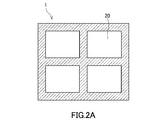
- a mold will be described with reference to FIGS.
- FIG. 1 shows a molded body (A) 100 and a mold 1 that accommodates the molded body (A) 100.
- the mold 1 shown in FIG. 2A can accommodate a molded body (A) 100 of an inorganic filler in a storage space 20 inside thereof.
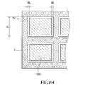
- FIG. 2B shows a cross-sectional view along the horizontal direction of the mold 1 after the molded body (A) 100 is accommodated in the accommodating space 20 in the step (P-1).
- the mold 1 has an accommodation space 20 having a width L 1 sufficient to accommodate the molded body (A) 100. Therefore, the coating layer (Y), which is a cured product of the polymerizable monomer (b), can cover at least all surfaces in the circumferential direction of the prismatic shaped molded body (A).
- the width means the length of one side of a certain surface.
- the mold 1 When the molded body (A) is accommodated in the accommodating space 20, the mold 1 generates a gap W 1 that matches the thickness of the coating layer described above between the molded body (A) and the accommodating space 20. because it is, when contacting a polymerizable monomer-containing composition (B) in the molded body (a), polymerizable monomer-containing composition by surface tension (B) intrudes into the gap W 1, gap A coating layer having a sufficient buffering effect on W 1 can be formed.
- the size of the dental mill blank is appropriately selected according to the application.
- the width (L 1 ⁇ 2W 1 ) of the molded body (A) is 10.0 mm or more and 15.0 mm.
- the width (L 1 -2W 1) be a less than 15.0 mm 20.0 mm, width (L 1 -2W 1) the length of the gap W 1 of the molded article (A) of the molded article (A)
- the ratio of L 1 ⁇ 2W 1 : W 1 2000: 1 to 25: 1 is preferable, 1900: 1 to 30: 1 is more preferable, and cracks during barrel polishing can be reduced. More preferred is 800: 1 to 35: 1.
- the material of the mold is not particularly limited as long as the desired mill blank can be produced.
- Amorphous polyolefins such as: Polyesters such as polyethylene terephthalate and polyethylene-2,6-naphthalate; Polyamides such as nylon 6, nylon 66, nylon 12, copolymer nylon; Polyvinyl alcohol; Partial hydrolysis of ethylene-vinyl acetate copolymer Polyimide; Polyetherimide; Polysulfone; Polyethersulfone; Polyetheretherketone; Polycarbonate; Polyvinyl butyral; Polyarylate; Teflon (registered trademark, PTFE) Resin; acrylate resin; biodegradable resin; stainless steel (SUS304, SUS430, etc.) metals or alloys such like.
- the mold is made of a fluororesin excellent in peelability, or the surface of the above-mentioned material other than the fluororesin is coated with a fluororesin Is particularly preferred.
- the shape of the mold used for manufacturing the mill blank is not particularly limited as long as the target mill blank can be manufactured.
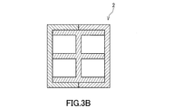
- the mold 2 is composed of three parts as shown in FIGS. 3A and 3B.
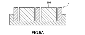
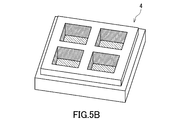
- it may be a mold 3 composed of three parts as shown in FIG. 4 or a mold 4 provided with a bottom as shown in FIGS. 5A and 5B.
- a coating layer (Y) may be provided on the molded body (A) and the bottom surface by using the mold 4 that can cover the bottom shown in FIGS. 5A and 5B.
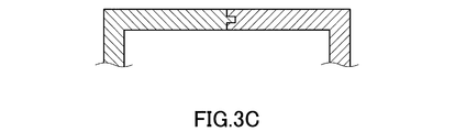
- FIG. 3A or 4 when a mold is composed of two or more parts, the shape of each component part is engaged with each part to accommodate the molded body (A), and a gap of a predetermined size is generated.
- the shape is not particularly limited as long as it is possible, and may be a fitting shape as shown in FIG. 3C or 3D.
- the mold 1 is placed inside the mold container.
- the mold container is not particularly limited as long as it does not elute into the composition (B) and has sealing properties, and a known packaging material can be used.
- the material of the mold container include amorphous polyolefins such as homopolymers or copolymers (eg, polyethylene, polypropylene) such as ethylene, propylene, and butene, and cyclic polyolefins; polyethylene terephthalate, polyethylene-2 Polyester such as nylon 6, nylon 66, nylon 12 and copolymer nylon; polyvinyl alcohol; ethylene-vinyl acetate copolymer partial hydrolyzate (EVOH); polyimide; polyetherimide; polysulfone; Polyethersulfone; Polyetheretherketone; Polycarbonate; Polyvinyl butyral; Polyarylate; Fluororesin such as Teflon (registered trademark, PTFE); Acrylate resin; Biodegradable resin and the like.
- FIG. 6 shows an embodiment of the contact (for example, impregnation) step (I) between the molded body (A) and the composition (B).
- the composition (B) is sealed inside the mold container 120 in which the mold 1 in which the molded body (A) is accommodated in the accommodation space 20 is arranged, and the composition (A) is composed. Impregnate the product (B). More specifically, the composition (B) enclosed in the mold container 120 is brought into contact with the molded body (A) 100 via the bottom surface 101 and the top surface 102 exposed to the outside, whereby the bottom surface 101 and the top surface 102. Thus, the composition (B) 110 is impregnated into the molded body (A) 100.
- composition (B) 110 impregnated in the molded body (A) 100 oozes out from the side surface 103 of the molded body (A) 100 into the gap 201 between the molded body (A) and the mold.
- the gap (201) is filled with the composition (B) 110.
- the gap 201 filled with the composition (B) is substantially composed of only the composition (B). Substantially free of inorganic filler.
- the viscosity of the composition (B) affects the penetration rate into the molded body (A). Usually, the lower the viscosity of the composition (B), the faster the penetration into the molded body (A).
- the viscosity (25 ° C.) of the composition (B) is preferably 10,000 mPa ⁇ s or less, more preferably 5000 mPa ⁇ s or less, and further preferably 2000 mPa ⁇ s or less.
- the composition (B) may be diluted with a solvent so as to have the viscosity. In selecting the composition (B), it is necessary to consider mechanical strength and refractive index in addition to viscosity.
- the composition (B) may be comprised only from the polymerizable monomer (b), and may be comprised from what melt
- the solvent may be distilled off by allowing the composition (B) to penetrate into the molded body (A) and then performing a decompression operation.
- the temperature at the time of making a molded object (A) and a composition (B) contact is 25 degreeC or more, and it is more preferable that it is 30 degreeC or more.
- the temperature at the time of the contact is preferably 70 ° C. or less, and more preferably 60 ° C. or less.
- the time for contacting the molded body (A) and the composition (B) is the kind of inorganic filler contained in the molded body (A), the size of the mold and the molded body (A), the molded body (A) and the composition. What is necessary is just to set suitably according to the method etc. which contact the thing (B), For example, 12 hours-48 hours are preferable, and 16 hours-24 hours are more preferable.
- the pressure may be reduced in order to more efficiently impregnate the molded body (A) with the composition (B).
- the degree of reduced pressure is, for example, preferably 100 hPa (10 kPa) or less, and may be 0.001 to 50 hPa (0.0001 to 5 kPa).
- the polymerizable monomer (b) contained in the composition (B) is polymerized in a state where the mold and the composition (B) are contained in the mold container (step (II)).
- the mold 1 is taken out from the mold container 120, the mold 1 is removed, and an excessive polymer portion is removed as necessary, whereby a dental mill blank as shown in FIG. 7 is obtained.
- the mill blank includes a mill blank portion (X) including an inorganic filler and a polymer (cured product of the polymerizable monomer) having a polymerizable monomer (b) unit, and polymerization.
- a coating layer (Y) containing a polymer having a functional monomer (b) unit containing a polymer having a functional monomer (b) unit. Moreover, since the composition (B) with which it filled in the clearance gap does not contain an inorganic filler substantially as above-mentioned, the coating layer (Y) obtained does not contain an inorganic filler substantially.
- the mill blank portion (X) is obtained by bringing the inorganic filler molded body (A) and the composition (B) containing the polymerizable monomer (b) into contact with each other in the mold (A). It is obtained by polymerizing a polymerizable monomer after impregnating B).
- the content of the polymerizable monomer (b) in the mill blank part (X) can be appropriately adjusted depending on the contact conditions between the molded body (A) and the composition (B).
- the molded body (A) is impregnated between the interior of the particle Polymerizable monomer (b), and a polymerizable monomer which is filled in the gap W 1 of the mold (b) Is produced by polymerizing and curing. Since the mold containing the compact (A) is impregnated with the composition (B) in the mold container and then polymerized in the mold container, the polymerization is preferably batch polymerization.
- the composition (B) may contain a polymerization initiator (c) in order to facilitate polymerization and curing.
- a polymerization initiator (c) will not be specifically limited if it is a well-known polymerization initiator, It is preferable that it is a polymerization initiator used for a dental material.
- the polymerization initiator may be a thermal polymerization initiator (c1), a photopolymerization initiator (c2) and a chemical polymerization initiator (c3), or a combination of two or more polymerization initiators.
- thermal polymerization initiator (c1) examples include organic peroxides and azo compounds.
- Examples of the organic peroxides used as the thermal polymerization initiator (c1) include ketone peroxide, hydroperoxide, diacyl peroxide, dialkyl peroxide, peroxyketal, peroxyester, peroxydicarbonate, and the like. Can be mentioned.
- ketone peroxide examples include methyl ethyl ketone peroxide, methyl isobutyl ketone peroxide, methyl cyclohexanone peroxide, and cyclohexanone peroxide.
- hydroperoxide examples include 2,5-dimethylhexane-2,5-dihydroperoxide, diisopropylbenzene hydroperoxide, cumene hydroperoxide, t-butyl hydroperoxide, and 1,1,3,3. -Tetramethylbutyl hydroperoxide and the like.
- diacyl peroxide examples include acetyl peroxide, isobutyryl peroxide, benzoyl peroxide, decanoyl peroxide, 3,5,5-trimethylhexanoyl peroxide, 2,4-dichlorobenzoyl peroxide, and lauroyl peroxide.
- examples include oxides.
- dialkyl peroxide examples include di-t-butyl peroxide, dicumyl peroxide, t-butylcumyl peroxide, 2,5-dimethyl-2,5-di (t-butylperoxy) hexane, , 3-bis (t-butylperoxyisopropyl) benzene, 2,5-dimethyl-2,5-di (t-butylperoxy) -3-hexyne and the like.
- peroxyketal examples include 1,1-bis (t-butylperoxy) -3,3,5-trimethylcyclohexane, 1,1-bis (t-butylperoxy) cyclohexane, and 2,2-bis. Examples thereof include (t-butylperoxy) butane, 2,2-bis (t-butylperoxy) octane, and 4,4-bis (t-butylperoxy) valeric acid-n-butyl ester.
- peroxyester examples include ⁇ -cumylperoxyneodecanoate, t-butylperoxyneodecanoate, t-butylperoxypivalate, 2,2,4-trimethylpentylperoxy-2- Ethyl hexanoate, t-amyl peroxy-2-ethyl hexanoate, t-butyl peroxy-2-ethyl hexanoate, di-t-butyl peroxy isophthalate, di-t-butyl peroxy hexahydro
- Examples include terephthalate, t-butylperoxy-3,3,5-trimethylhexanoate, t-butylperoxyacetate, t-butylperoxybenzoate, and t-butylperoxymaleic acid.
- peroxydicarbonate examples include di-3-methoxybutyl peroxydicarbonate, di-2-ethylhexyl peroxydicarbonate, bis (4-t-butylcyclohexyl) peroxydicarbonate, and diisopropyl peroxydicarbonate. Di-n-propyl peroxydicarbonate, di-2-ethoxyethyl peroxydicarbonate, diallyl peroxydicarbonate, and the like.
- the organic peroxides are preferably diacyl peroxides and more preferably benzoyl peroxides from the viewpoints of safety, storage stability and radical generating ability.
- azo compounds examples include 2,2′-azobisisobutyronitrile, 2,2′-azobis (2,4-dimethylvaleronitrile), 4,4′-azobis (4-cyanovaleric acid). ), 1,1′-azobis (cyclohexane-1-carbonitrile), dimethyl-2,2′-azobis (isobutyrate), 2,2′-azobis (2-aminopropane) dihydrochloride and the like.
- Examples of the photopolymerization initiator (c2) include (bis) acylphosphine oxides, ⁇ -diketones, and coumarins.
- Examples of the (bis) acylphosphine oxides include 2,4,6-trimethylbenzoyldiphenylphosphine oxide, 2,6-dimethoxybenzoyldiphenylphosphine oxide, 2,6-dichlorobenzoyldiphenylphosphine oxide, 2,4,6 -Trimethylbenzoylmethoxyphenylphosphine oxide, 2,4,6-trimethylbenzoylethoxyphenylphosphine oxide, 2,3,5,6-tetramethylbenzoyldiphenylphosphine oxide, benzoyldi- (2,6-dimethylphenyl) phosphonate, and these Acylphosphine oxides such as bis (2,6-dichlorobenzoyl) phenylphosphine oxide, bis (2,6dichlorobenzoyl) -2,5-dimethyl Ruphenylphosphine oxide, bis (2,6-dichlorobenzoyl) -4-prop
- the acylphosphine oxides are preferably 2,4,6-trimethylbenzoyldiphenylphosphine oxide, 2,4,6-trimethylbenzoylmethoxyphenylphosphine oxide and 2,4,6-trimethylbenzoylphenylphosphine oxide sodium salt.
- the bisacylphosphine oxide is preferably bis (2,4,6-trimethylbenzoyl) phenylphosphine oxide.
- ⁇ -diketone examples include diacetyl, dibenzyl, camphorquinone, 2,3-pentadione, 2,3-octadione, 9,10-phenanthrenequinone, 4,4′-oxybenzyl, acenaphthenequinone and the like. Is mentioned.
- camphorquinone is preferable as the ⁇ -diketone used as the photopolymerization initiator.
- Examples of the coumarins include 3,3′-carbonylbis (7-diethylaminocoumarin), 3- (4-methoxybenzoyl) coumarin, 3-thienoylcoumarin, 3-benzoyl-5,7-dimethoxycoumarin, 3 -Benzoyl-7-methoxycoumarin, 3-benzoyl-6-methoxycoumarin, 3-benzoyl-8-methoxycoumarin, 3-benzoylcoumarin, 7-methoxy-3- (p-nitrobenzoyl) coumarin, 3- (p- Nitrobenzoyl) coumarin, 3,5-carbonylbis (7-methoxycoumarin), 3-benzoyl-6-bromocoumarin, 3,3'-carbonylbiscoumarin, 3-benzoyl-7-dimethylaminocoumarin, 3-benzoylbenzo [F] Coumarin, 3-carboxycoumarin, 3-carboxy-7 Methoxycoumarin, 3-ethoxycarbonyl-6-methoxycoumarin, 3-ethoxy
- 3,3′-carbonylbis (7-diethylaminocoumarin) and 3,3′-carbonylbis (7-dibutylaminocoumarin) are preferable.
- the photopolymerization initiator (c2) it is preferable to use at least one selected from the group consisting of (bis) acylphosphine oxides, ⁇ -diketones, and coumarins widely used in dental composite resins.
- the composition (B) may contain a polymerization accelerator as necessary.
- a polymerization accelerator When the composition (B) contains a polymerization accelerator, photopolymerization can be efficiently performed in a shorter time.
- polymerization accelerator examples include tertiary amines, aldehydes, compounds having a thiol group, sulfinic acid and salts thereof, and the like.
- tertiary amine examples include N, N-dimethylaniline, N, N-dimethyl p-toluidine, N, N-dimethyl-m-toluidine, N, N-diethyl-p-toluidine, N, N— Dimethyl-3,5-dimethylaniline, N, N-dimethyl-3,4-dimethylaniline, N, N-dimethyl-4-ethylaniline, N, N-dimethyl-4-isopropylaniline, N, N-dimethyl- 4-t-butylaniline, N, N-dimethyl-3,5-di-t-butylaniline, N, N-bis (2-hydroxyethyl) -3,5-di-t-butylaniline, N, N-bis (2-hydroxyethyl) -3,5-dimethylaniline, N, N-bis (2 -Hydroxyethyl) -p-toluidine, N, N-
- aldehydes examples include dimethylaminobenzaldehyde and terephthalaldehyde.
- examples of the compound having a thiol group include 2-mercaptobenzoxazole, decanethiol, 3-mercaptopropyltrimethoxysilane, and thiobenzoic acid.
- sulfinic acid and its salts examples include benzenesulfinic acid, sodium benzenesulfinate, potassium benzenesulfinate, lithium benzenesulfinate, calcium benzenesulfinate, p-toluenesulfinate, sodium p-toluenesulfinate, p- Potassium toluenesulfinate, lithium p-toluenesulfinate, calcium p-toluenesulfinate, 2,4,6-trimethylbenzenesulfinic acid, sodium 2,4,6-trimethylbenzenesulfinate, 2,4,6-trimethylbenzene Potassium sulfinate, lithium 2,4,6-trimethylbenzenesulfinate, calcium 2,4,6-trimethylbenzenesulfinate, 2,4,6-triethylbenzenesulfinate, 2,4,6 -Sodium triethylbenzenesulfinate, potassium 2,4,6-tritri
- the chemical polymerization initiator (c3) a redox polymerization initiator in which an organic peroxide and a polymerization accelerator are combined is preferable.
- the organic peroxide used for a chemical polymerization initiator is not specifically limited, A well-known thing can be used. Examples thereof include organic peroxides used as the thermal polymerization initiator (c1).
- organic peroxide used for the chemical polymerization initiator (c3) diacyl peroxide is preferable and benzoyl peroxide is more preferable from the viewpoints of safety, storage stability and radical generating ability.
- the polymerization accelerator constituting the redox polymerization initiator may be a known polymerization accelerator, but is preferably a polymerization accelerator used for dental materials.
- the polymerization accelerator used for the chemical polymerization initiator (c3) may be a mixture of two or more.
- Examples of the polymerization accelerator constituting the redox polymerization initiator include amines, sulfinic acid and salts thereof, copper compounds, tin compounds and the like.
- amines examples include primary aliphatic amines such as n-butylamine, n-hexylamine and n-octylamine; secondary aliphatic amines such as diisopropylamine, dibutylamine and N-methylethanolamine; N-methyldiethanolamine, N-ethyldiethanolamine, Nn-butyldiethanolamine, N-lauryldiethanolamine, 2- (dimethylamino) ethyl methacrylate, N-methyldiethanolamine dimethacrylate, N-ethyldiethanolamine dimethacrylate, triethanolamine monomethacrylate Tertiary fats such as triethanolamine dimethacrylate, triethanolamine trimethacrylate, triethanolamine, trimethylamine, triethylamine, tributylamine N, N-bis (2-hydroxyethyl) -3,5-dimethylaniline, N, N-bis (2-hydroxyethyl)
- the amines used as the polymerization accelerator are preferably tertiary aliphatic amines, more preferably N-methyldiethanolamine and triethanolamine, from the viewpoints of curability and storage stability of the composition.
- the polymerization accelerator is N, N-bis (2-hydroxyethyl) -p-toluidine, ethyl 4- (N, N-dimethylamino) benzoate, It is preferable to include at least one selected from the group consisting of n-butoxyethyl 4- (N, N-dimethylamino) benzoate and 4- (N, N-dimethylamino) benzophenone.
- the sulfinic acid and salts thereof include the same as the polymerization accelerator of the photopolymerization initiator (c2).
- the sulfinic acid used as a polymerization accelerator constituting the redox polymerization initiator and its salt are preferably sodium benzenesulfinate, sodium p-toluenesulfinate, or sodium 2,4,6-triisopropylbenzenesulfinate.
- Examples of the copper compound include acetylacetone copper, cupric acetate, copper oleate, cupric chloride, cupric bromide and the like.
- tin compound examples include di-n-butyltin dimaleate, di-n-octyltin dimaleate, di-n-octyltin dilaurate, di-n-butyltin dilaurate, and di-n-octyltin. Dilaurate and di-n-butyltin dilaurate are preferred.
- polymerization initiator (c) those in which the thermal polymerization initiator (c1) and the photopolymerization initiator (c2) are used in combination are preferable, and in particular, (bis) acylphosphine oxides and diacyl peroxide are used in combination. Are preferred.
- content of the polymerization initiator (c) in a composition (B) is not specifically limited, From viewpoints of sclerosis
- the content of the polymerization initiator (c) is preferably 0.05 parts by weight or more and more preferably 0.1 parts by weight or more with respect to 100 parts by weight of the polymerizable monomer (b).
- the content of the polymerization initiator (c) is 30 parts by weight or less with respect to 100 parts by weight of the polymerizable monomer (b), even if the polymerization performance is low, A dental mill blank having sufficient mechanical strength is obtained, and further, there is no possibility that the polymerization initiator (c) is precipitated from the composition (B).
- the content of the polymerization initiator (c) is more preferably 20 parts by weight or less with respect to 100 parts by weight of the polymerizable monomer (b).
- the composition (B) contains a pH adjuster, an ultraviolet absorber, an antioxidant, a polymerization inhibitor, a colorant, a pigment, an antibacterial agent, an X-ray contrast agent, a thickener, a fluorescent agent, and the like depending on the purpose. You may go out.
- Composition (B) may contain, for example, a polymerizable monomer (b) and a polymerization initiator (c).
- the method for polymerizing the polymerizable monomer (b) is not particularly limited, and known methods such as heat polymerization, photopolymerization, and chemical polymerization can be used.
- the polymerizable monomer (b) is preferably polymerized by heat polymerization after being polymerized by photopolymerization.
- the heating temperature of the heat polymerization is not particularly limited, but is preferably about 40 to 150 ° C.
- the heat polymerization time is not particularly limited, but may be about 1 to 70 hours.
- the light used for photopolymerization may be visible light or UV light.
- the photopolymerization time is not particularly limited, but may be about 1 to 20 minutes.
- the polymerization rate of the polymerizable monomer can be increased by polymerizing the polymerizable monomer (b) under an inert atmosphere such as nitrogen gas or under a reduced pressure environment, and thus obtained.
- the mechanical strength of the dental mill blank is further increased.
- the polymerizable monomer (b) may be subjected to heat polymerization under pressure using an autoclave or the like.
- the heating temperature is not particularly limited, but is preferably 80 to 150 ° C.
- the heating time is not particularly limited, but is preferably 10 minutes to 5 hours.
- the present invention includes embodiments in which the above configurations are combined in various ways within the technical scope of the present invention as long as the effects of the present invention are exhibited.
- a photopolymerization initiator (c2) is added to 50 parts by weight of 2,2-bis [4- [3-methacryloyloxy-2-hydroxypropoxy] phenyl] propane (Bis-GMA) and 50 parts by weight of hexanediol dimethacrylate (HD).
- TMDPO 2,4,6-trimethylbenzoyldiphenylphosphine oxide
- BPO benzoyl peroxide
- inorganic particles (a) for 1 hour, and then the same operation as in Production Example 2 of inorganic particles (a) is performed on 100 g of the aggregated particles using 20 g of ⁇ -methacryloyloxypropyltrimethoxysilane and 10 g of water. Thus, surface-treated inorganic particles (a-5) were obtained.
- the Teflon mold 1 (FIG. 2A) has four accommodating spaces that have substantially the same shape as the molded body (A-1).
- the inner size of one storage space 20 of the mold 1 is 14.92 mm width ⁇ 18.42 mm depth ⁇ 15.00 mm height.
- the compact (A-1) was accommodated in each accommodating space 20 of the mold 1.
- the mold 1 containing the molded body (A-1) in the accommodation space was placed inside a polyethylene bag.
- the solution of the composition (B-1) was introduced into the bag body, and the molded body (A-1) was allowed to stand at room temperature for 1 day under the condition that the pressure inside the bag body was reduced to 0.001 kPa or less.
- the molded body (A-1) was impregnated with the composition (B-1). Thereafter, the gap W 1 of the mold 1, was visually confirmed that the composition (B-1) is satisfied.
- the molded body (A-1) impregnated with the composition (B-1) is placed in a bag body, it is heated at 55 ° C. for 18 hours using a hot air dryer, and further at 110 ° C. for 3 hours. Then, the polymerizable monomer was polymerized to obtain a mill blank (C-1).
- the mill blank (C-1) was provided with a prismatic mill blank portion of 14.90 mm ⁇ 18.40 mm ⁇ 15.00 mm and a coating layer having a thickness of 0.01 mm on four circumferential surfaces. .
- the thickness of the mill blank part and the coating layer was measured using a color 3D laser microscope (VK-9710, manufactured by KEYENCE). The result of observation photograph is shown in FIG.
- Example 2 A molded body (A-1) is formed in each housing space 20 of the same mold 1 as in Example 1 except that the inner dimension of one housing space 20 is 15.50 mm width ⁇ 19.00 mm depth ⁇ 15.00 mm height.
- a mill blank (C-2) was produced in the same manner as in Example 1. The mill blank (C-2) was provided with a prismatic mill blank portion of 14.90 mm ⁇ 18.40 mm ⁇ 15.00 mm and a coating layer having a thickness of 0.30 mm on four circumferential surfaces. .
- Example 3 A molded body (A-1) is placed in each housing space 20 of the same mold 1 as in Example 1 except that the inner dimension of one housing space 20 is 15.90 mm width ⁇ 19.40 mm depth ⁇ 15.00 mm height.
- a mill blank (C-3) was produced in the same manner as in Example 1. The mill blank (C-3) was provided with a prismatic mill blank portion of 14.90 mm ⁇ 18.40 mm ⁇ 15.00 mm and a coating layer having a thickness of 0.50 mm on four circumferential surfaces. .
- Example 4 A molded body (A-1) is formed in each housing space 20 of the same mold 1 as in Example 1 except that the inner dimension of one housing space 20 is 15.50 mm width ⁇ 19.00 mm depth ⁇ 15.00 mm height. Housed. The mold 1 containing the molded body (A-1) in the accommodation space was placed inside a polyethylene bag. Next, the composition (B-2) was introduced into the bag body, and the molded body (A-1) was allowed to stand at room temperature for 1 day under the condition that the inside of the bag body was decompressed to 0.001 kPa or less. The molded body (A-1) was impregnated with the composition (B-2). Thereafter, it was confirmed that the composition (B-2) was filled in the gap W 1 of the mold 1.
- the molded product (A-1) impregnated with the composition (B-2) is placed in a bag, and light is applied for 1 minute with a dental polymerization light irradiator (Pencure 2000, manufactured by Morita). After the irradiation, it was further subjected to a heat treatment at 110 ° C. for 3 hours to polymerize the polymerizable monomer to obtain a mill blank (C-4).
- the mill blank (C-4) was provided with a prismatic mill blank portion of 14.90 mm ⁇ 18.40 mm ⁇ 15.00 mm and a coating layer having a thickness of 0.30 mm on four circumferential surfaces. .
- the thickness of the mill blank portion and the coating layer was measured using a color 3D laser microscope (VK-9710, manufactured by KEYENCE).
- Examples 5 to 12 Mill blanks (C-5) to (C-12) were produced in the same manner as in Example 1. Table 2 below shows the internal dimensions of the molded body (A) used, the accommodation space 20 of the Teflon mold 1 (FIG. 2A), and the thickness of the formed coating layer.
- Table 2 shows the internal dimensions of the molded body (A) used, the accommodation space 20 of the Teflon mold 1 (FIG. 2A), and the thickness of the formed coating layer.
- a polyethylene bag body having an embossed inner surface was used.
- the coating layer was formed on the entire surface of 6 surfaces (4 surfaces in the circumferential direction and the upper and lower surfaces facing each other).
- the press-molded body (A-10) is placed inside a polyethylene bag body, and then the composition (B-1) is introduced into the bag body, and the interior of the bag body is decompressed to 0.001 kPa or less. Under such conditions, the molded product (A-10) was allowed to stand at room temperature for 3 days to impregnate the molded product (A-10) with the composition (B-1). Next, the molded article impregnated with the polymerizable monomer was heated at 55 ° C. for 18 hours using a hot air drier, and then further heated at 110 ° C. for 3 hours to obtain a polymerizable cured product.
- the polymerizable cured product was cut using a diamond cutter (Isomet 1000, manufactured by Buehler) to obtain a prism column-shaped mill blank of 14.80 mm ⁇ 18.40 mm ⁇ 14.70 mm. When confirmed with a laser microscope, no coating layer was seen.
- Test 1 The impact resistance of the obtained mill blank was evaluated by the following method using a Charpy impact tester (manufactured by Navik Corporation; arm length 105 mm, arm weight 300 g). A 3 mm ⁇ SUS chip was attached to a 300 g pendulum bar, and the prepared mill blank was set so that half the area of the 3 mm ⁇ SUS chip was in contact. When the position of the bar was set to 150 ° and the operation of colliding with the mill blank was repeated three times, the mill blank was chipped or damaged when cracks (breaks) of 1 mm or more could be visually confirmed. It was judged. The test results are shown in Table 2 below.
- Test 2 The impact resistance of the obtained mill blank was evaluated by the following method using a centrifugal barrel polishing machine (vertical centrifugal barrel, model: HS-1-4V, manufactured by Chipton Co., Ltd.). In a barrel tank, 1.5 kg of polishing stones, 600 mL of water, and 5 mL of barrel polishing liquid compound (LC-NZ-NP, manufactured by Chipton Co., Ltd.) were placed, and the produced mill blank was placed. After inserting the barrel tank into the barrel case and polishing for 45 minutes, the mill blank was judged to have been damaged when chipped or scratches (breaks) of 1 mm or more could be visually confirmed. The test results are shown in Table 2 below.
- the mill blank of the present invention is useful because it improves the production yield.
- the mill blank of the present invention is excellent in impact resistance during barrel polishing.
- Mold 100 Molded body 101 Bottom surface 102 Top surface 103 Side surface 110 Composition (B) 120 Mold storage container 20 Storage space 201 Clearance 300 Dental mill blank 310 Mill blank part (X) 320 Coating layer (Y)
Landscapes
- Health & Medical Sciences (AREA)
- Oral & Maxillofacial Surgery (AREA)
- Epidemiology (AREA)
- Life Sciences & Earth Sciences (AREA)
- Animal Behavior & Ethology (AREA)
- General Health & Medical Sciences (AREA)
- Public Health (AREA)
- Veterinary Medicine (AREA)
- Dentistry (AREA)
- Plastic & Reconstructive Surgery (AREA)
- Dental Preparations (AREA)
- Dental Prosthetics (AREA)
Abstract
本発明は、ミルブランク部(X)と、前記ミルブランク部(X)の少なくとも周方向のすべての面を被覆するコーティング層(Y)とを備え、前記ミルブランク部(X)が無機充填材と重合性単量体(b)の硬化物とを含有し、前記コーティング層(Y)が無機充填材を実質的に含まず重合性単量体(b)の硬化物を含有し、角柱状である歯科用ミルブランクに関する。
Description
本発明は、歯科用ミルブランク及びその製造方法に関する。さらに詳しくは、例えば、歯科用CAD/CAMシステムでの切削加工による、インレー、オンレー、ベニア、クラウン、ブリッジ、支台歯、歯科用ポスト、義歯、義歯床、インプラント部材(フィクスチャー、アバットメント)等の歯科用補綴物の作製に好適に用いられる歯科用ミルブランク及びその製造方法に関する。
近年、インレー、クラウン等の歯科用補綴物を、コンピューターによって設計し、ミリング装置により切削加工して作製するCAD/CAMシステムが普及している。一般に、CAD/CAMシステムに用いられる被切削材料である歯科用ミルブランクは、切削加工に供されるミルブランク部と、ミルブランク部から突出し、ミルブランク部をミリング装置に固定するための支持部と、を含む。
ミルブランク部の素材としては、審美性の観点から、セラミック材料が一般に用いられてきた。ところが、セラミック製ミルブランクから作製された歯科用補綴物は、硬度が高い脆性材料であるため、対合歯に損傷を与えるだけでなく、切削加工又は咬合の衝撃によって欠けが生じるといった課題があった。
このような課題を解決するために、最近では、ポリマーと無機充填材を含む複合材料からなるミルブランク部の検討が行なわれている。ミルブランク部は、対合歯を傷つけない適度な硬度を有し、クラウン形状においても耐衝撃性に優れることから歯科用補綴物に加工されて臨床で使われ始めている。
前記複合材料からなるミルブランク部の製造方法として、特許文献1~5には、無機充填材と重合性単量体とを混合練和して得られた均一なペースト状の組成物(コンポジットレジン)を鋳型に流し込み、鋳型の中で加熱重合、光重合等の重合を行うことによって、硬化物であるミルブランク部を得る方法が開示されている。コンポジットレジンからミルブランク部を得る方法では、重合前のコンポジットレジンが、ある程度高い流動性を有する必要があり、無機充填材の配合比率を上げることが困難である。そのため、前記ミルブランク部から得られた歯科用補綴物は、機械的強度、耐摩耗性及び表面滑沢性が十分ではない。
これに対して、特許文献6には、無機充填材の成形体と重合性単量体を含む組成物とを接触させて成形体に重合性単量体を含浸させたあとに、重合性単量体を重合させることによって、ミルブランク部を製造する方法が開示されている。このような方法で得られたミルブランク部からは、機械的強度、耐摩耗性、表面滑沢性、及び対合歯の耐摩耗性に優れる歯科用補綴物を得ることができる。
しかしながら、上記特許文献6に記載されている製造方法においても、ダイヤモンドカッターにより所定の大きさの角柱状のブロックに切断されて得られるミルブランクは、特に角、又は縁部分において、ミルブランク製品の製造工程内あるいは製造後の製品運搬時の衝撃によって、チッピングあるいは欠けが生じやすく、製品外観上の不合格となり、歩留まりが低下するという問題があった。また、製品使用前においても、落下により製品が破損し、使用できなくなる場合がある。
本発明は、製品製造上において耐衝撃性に優れる歯科用ミルブランクとその簡便な製造方法を提供することを目的とする。特に、バレル研磨時の耐衝撃性に優れる歯科用ミルブランクとその製造方法を提供することを目的とする。
本発明は、
ミルブランク部(X)と、前記ミルブランク部(X)の少なくとも周方向のすべての面(外周面)を被覆するコーティング層(Y)とを備え、
前記ミルブランク部(X)が無機充填材と重合性単量体(b)の硬化物とを含有し、
前記コーティング層(Y)が無機充填材を実質的に含まず重合性単量体(b)の硬化物を含有し、角柱状である歯科用ミルブランクを提供する。
ミルブランク部(X)と、前記ミルブランク部(X)の少なくとも周方向のすべての面(外周面)を被覆するコーティング層(Y)とを備え、
前記ミルブランク部(X)が無機充填材と重合性単量体(b)の硬化物とを含有し、
前記コーティング層(Y)が無機充填材を実質的に含まず重合性単量体(b)の硬化物を含有し、角柱状である歯科用ミルブランクを提供する。
また、本発明は、
鋳型内において、角柱状である無機充填材の成形体(A)と重合性単量体(b)を含む重合性単量体含有組成物(B)とを接触させる工程(I)、
前記鋳型内において、組成物(B)に含まれる重合性単量体(b)を重合させる工程(II)を有し、
前記鋳型は、重合性単量体(b)の硬化物であるコーティング層(Y)が少なくとも角柱状の成形体(A)の周方向のすべての面を被覆できるように、成形体(A)を収容する収容空間を備え、
前記収容空間は、少なくとも周方向のすべての面において、収容された成形体(A)の端面と鋳型の収容空間の内壁面との間に隙間を有するサイズである、
上記した歯科用ミルブランクの製造方法を提供する。
鋳型内において、角柱状である無機充填材の成形体(A)と重合性単量体(b)を含む重合性単量体含有組成物(B)とを接触させる工程(I)、
前記鋳型内において、組成物(B)に含まれる重合性単量体(b)を重合させる工程(II)を有し、
前記鋳型は、重合性単量体(b)の硬化物であるコーティング層(Y)が少なくとも角柱状の成形体(A)の周方向のすべての面を被覆できるように、成形体(A)を収容する収容空間を備え、
前記収容空間は、少なくとも周方向のすべての面において、収容された成形体(A)の端面と鋳型の収容空間の内壁面との間に隙間を有するサイズである、
上記した歯科用ミルブランクの製造方法を提供する。
本発明は、製品製造上において耐衝撃性に優れる歯科用ミルブランクとその簡便な製造方法を提供することができる。特に、バレル研磨時の耐衝撃性に優れる歯科用ミルブランクとその製造方法を提供することができる。
本発明の歯科用ミルブランクは、ミルブランク部(X)と、前記ミルブランク部(X)の少なくとも周方向のすべての面を被覆するコーティング層(Y)とを備え、
前記ミルブランク部(X)が無機充填材と重合性単量体(b)の硬化物とを含有し、
前記コーティング層(Y)が無機充填材を実質的に含まず重合性単量体(b)の硬化物を含有し、角柱状である。
前記ミルブランク部(X)が無機充填材と重合性単量体(b)の硬化物とを含有し、
前記コーティング層(Y)が無機充填材を実質的に含まず重合性単量体(b)の硬化物を含有し、角柱状である。
角柱状は、特に限定されないが、直方体状、立方体状、正五角柱状、正六角柱状、正八角柱状等の形状が挙げられ、直方体状又は立方体状が好ましい。また、例えば、形状が直方体状又は立方体状である場合、本発明の効果を奏する限り、角が丸い、略直方体状又は略立方体状であってもよい。
ミルブランク部(X)に含有される無機充填材としては、特に限定されず、公知の無機粒子を使用でき、コンポジットレジンの充填材として用いられる公知の無機粒子(a)が好ましい。無機粒子(a)としては、例えば、各種ガラス類(二酸化ケイ素(石英、石英ガラス、シリカゲル等)又はケイ素を主成分とし、各種重金属とともにホウ素及び/又はアルミニウムを含有するもの)、アルミナ、各種セラミック類、珪藻土、カオリン、粘土鉱物(モンモリロナイト等)、活性白土、合成ゼオライト、マイカ、シリカ、フッ化カルシウム、フッ化イッテルビウム、リン酸カルシウム、硫酸バリウム、二酸化ジルコニウム(ジルコニア)、二酸化チタン(チタニア)、ヒドロキシアパタイト等が挙げられる。また、無機充填材は、前記無機粒子(a)に重合性単量体を添加し、重合硬化させた後に粉砕することによって得られる有機無機複合粒子(有機無機複合フィラー)を含んでもよい。さらに、無機充填材は、2種以上の無機粒子(a)を含んでもよい。
本発明の歯科用ミルブランクが切削加工されることによって、機械的物性、耐摩耗性、及び滑沢性に優れた審美的な歯科用補綴物を得ることができる。
本発明のミルブランクから製造される歯科用補綴物としては、例えば、インレー、オンレー、ベニア、クラウン、ブリッジ等の歯冠修復物;支台歯;歯科用ポスト;義歯;義歯床;インプラント部材(フィクスチャー、アバットメント)等の欠損治療用材料が挙げられる。また、切削加工に用いられる歯科用CAD/CAMシステムとしては、例えば、シロナデンタルシステムズ社製のCERECシステム、及び、クラレノリタケデンタル社製のカタナシステムが挙げられる。
歯科用補綴物は、天然歯と同様の透明性及びX線造影性を有することが求められる。透明性は、無機充填材の屈折率を重合性単量体の重合体の屈折率に近づけることによって調整することができる。また、X線造影性は、無機充填材がジルコニウム、バリウム、チタン、ランタン、ストロンチウム等の重金属元素の酸化物を含むことによって得ることができる。重金属元素を含む無機充填材の屈折率は通常高く、1.5~1.6の範囲内にある。また、(メタ)アクリレート系重合性単量体に由来する重合体の屈折率は通常、1.5~1.6の範囲内にある。したがって、重合性単量体として(メタ)アクリレート系重合性単量体を用いた場合には、重金属元素を含む無機充填材との屈折率差が小さいため、得られるミルブランク部(X)は、X線造影性だけでなく優れた透明性を有する。
X線造影性を有し、屈折率が高い無機充填材に含まれる無機粒子(a)としては、例えば、バリウムボロアルミノシリケートガラス(例えば、Esstech社製E3000;ショット社製8235、GM27884、GM39923)、ストロンチウムボロアルミノシリケートガラス(例えばEsstech社製E4000;ショット社製G018-093、GM32087)、ランタンガラス(例えばショット社製GM31684)、フルオロアルミノシリケートガラス(例えばショット社製G018-091、G018-117)、ジルコニアを含有するガラス(例えばショット社製G018-310、G018-159)、ストロンチウムを含有するガラス(例えばショット社製G018-163、G018-093、GM32087)、酸化亜鉛を含有するガラス(例えばショット社製G018-161)、カルシウムを含有するガラス(例えばショット社製G018-309)等が挙げられる。
無機充填材に含まれる無機粒子(a)の形状は特に限定されず、例えば、破砕状、板状、鱗片状、繊維状(短繊維、長繊維)、針状、ウィスカー、球状であってもよい。無機粒子(a)は、前記形状の一次粒子が凝集したものでもよく、異なる形状の一次粒子が複数混合されたものでもよい。また、前記形状となるように、無機粒子(a)は何らかの処理(例えば、粉砕)を施されたものであってもよい。
無機粒子(a)の粒子径は、プレス成形に供することができる限り、特に限定されない。例えば、平均粒子径は、1.0nm~20μm(好適には粒径範囲:0.50nm~50μm)であり、2.0nm~10μm(好適には粒径範囲:0.50nm~20μm)であることが好ましく、2.0nm~5.0μm(好適には粒径範囲:0.50nm~20μm)であることがより好ましく、5.0nm~3.0μm(好適には粒径範囲:1.0nm~10μm)であることがさらに好ましく、5.0nm~1.0μm(好適には粒径範囲:1.0nm~3.0μm)であることが特に好ましい。また、無機粒子(a)が繊維状である場合には、例えば、平均繊維長は、1.0~100μmであり、平均繊維径は、0.10~30μmである。なお、本明細書において、無機粒子の粒子径とは、無機粒子の一次粒子の粒子径(平均一次粒子径)を意味し、粒径範囲とは、無機粒子の一次粒子の95%以上が含まれる粒子径の範囲を意味する。本発明の効果を損なわない範囲内であれば、粒径範囲に含まれない無機粒子が無機充填材に含まれてもよい。
なお、本明細書において、無機粒子の平均粒子径は、レーザー回折散乱法又は電子顕微鏡観察により求めることができる。具体的には、0.10μm以上の粒子径を有する無機粒子については、レーザー回折散乱法によって粒子径を簡便に測定することができる。また、0.10μm未満の粒子径を有する無機粒子(超微粒子)については、電子顕微鏡観察によって粒子径を簡便に測定することができる。0.10μmはレーザー回折散乱法により測定した値である。
レーザー回折散乱法の装置としては、例えば、レーザー回折式粒度分布測定装置(SALD-2100、島津製作所製)を用いることができる。このとき、分散媒としては0.2%ヘキサメタリン酸ナトリウム水溶液が用いられる。
電子顕微鏡観察は、例えば、透過型電子顕微鏡(日立製作所製、H-800NA型)を用いることができる。電子顕微鏡によって撮影された写真の単位視野内に観察される粒子(200個以上)の粒子径は、画像解析式粒度分布測定ソフトウェア(Macview(株式会社マウンテック))によって求めることができる。このとき、粒子径は、同一の面積を有する正円の径として求められる。また、粒子数及び、それぞれの粒子の粒子径から平均一次粒子径が算出される。
無機粒子は、本発明の効果を損なわない範囲で、異なった材質、粒度分布、形態を有する2種以上の無機粒子が併用されてもよい。また、本発明の効果を損なわない範囲であれば、無機粒子以外の粒子が不純物として含まれてもよい。
以下に、本発明における無機充填材の好ましい態様を挙げる。
本発明において、無機充填材は、無機粒子(a)として、平均粒子径が0.10μm以上1.0μm未満(好適には粒径範囲:0.050~5.0μm)である無機粒子(サブミクロンフィラー)(a1)を含んでもよい。特に、サブミクロンフィラー(a1)は、平均粒子径が0.10μm以上0.50μm以下(好適には粒径範囲:0.050~5.0μm)であることが好ましく、0.10μm以上0.30μm以下(好適には粒径範囲:0.050~5.0μm)であることがより好ましい。前記サブミクロンフィラー(a1)を含む無機充填材を用いて製造されたミルブランク部(X)は、機械的強度及び審美性(耐摩耗性、滑沢性等)を備えた歯科用補綴物を与えることができる。ある実施形態において、無機充填材におけるサブミクロンフィラー(a1)の含有率は、90重量%以上であることが好ましく、95重量%以上であることがより好ましく、実質的に100重量%であることが好ましい。また、本明細書において、無機充填材に含まれる特定の無機粒子の含有量は、ミルブランク部が積層構造体の場合、ある特定の層(例えば、エナメル色層)に含まれる無機粒子の量を意味するものであってもよい。
また、前記サブミクロンフィラー(a1)は、球状粒子であることが好ましい。本明細書において、球状とは、略球状を含み、完全真球に限定されない。例えば、平均均斉度は、0.6以上であることが好ましく、0.8以上であることがより好ましく、0.9以上であることがさらに好ましい。ここで、均斉度とは、粒子の最大径に対する最大径に直交する方向の粒子径の比である。また、平均均斉度とは、走査型電子顕微鏡を用いて撮影されたサブミクロンフィラー(a1)の写真の単位視野内に観察される任意の30個の粒子における均斉度の平均値である。
サブミクロンフィラー(a1)は、シリカ粒子と、周期律表第2族、同第4族、同第12族、及び同第13族からなる群より選ばれる少なくとも1種の金属原子又はその酸化物と、ケイ素原子と、酸素原子とを含む複合酸化物粒子であることが好ましい。複合酸化物粒子は、例えば、非晶質シリカ、石英、クリストバライト、トリジマイト;アルミナ、二酸化チタン、酸化ストロンチウム、酸化バリウム、酸化亜鉛、酸化ジルコニウム、酸化ハフニウム;シリカジルコニア、シリカチタニア、シリカチタニア酸化バリウム、シリカアルミナ、シリカチタニアナトリウムオキサイド、シリカチタニアカリウムオキサイド、シリカジルコニアナトリウムオキサイド、シリカジルコニアカリウムオキサイド、シリカバリウムオキサイド、シリカストロンチウムオキサイド等である。特に、サブミクロンフィラー(a1)が球状である実施形態では、シリカ粒子と、周期律表第4族の金属原子と、周期律表第4族の金属酸化物と、ケイ素原子と、酸素原子とを含む複合酸化物粒子であるものがより好ましい。さらに、X線造影性を有し、耐摩耗性に優れた歯科用ミルブランクが得られることから、サブミクロンフィラー(a1)が球状である実施形態では、シリカジルコニアであるものが好ましい。球状のサブミクロンフィラー(a1)の製造方法は、例えば、特開昭58-110414号公報又はWO2009/133913号に記載されている。また、球状のサブミクロンフィラー(a1)として、ヒドロキシアパタイトを用いることもできる。
なお、サブミクロンフィラー(a1)が球状である実施形態において、フィラーの比表面積は、好ましくは5~25m2/gである。本明細書において、比表面積は、比表面積BET法により、常法に従って測定した値である。
本発明者らの検討によれば、球状のサブミクロンフィラー(a1)を用いた場合、通常、歯科用コンポジットレジンにおける無機充填材の含有率が、80重量%を超えることは困難である。しかし、成形体(A)とすることによって、ミルブランク部におけるサブミクロンフィラー(a1)の含有率を、80重量%以上とすることができる。無機粒子(a)として球状のサブミクロンフィラー(a1)を用いる実施形態においては、ミルブランク部(X)における無機充填材の含有率は、80重量%以上であることが好ましく、84重量%以上であることがより好ましい。また、前記含有率は、95重量%以下であることが好ましく、92重量%以下であることがより好ましい。特に、前記含有率は、80~95重量%であることが好ましく、84~92重量%であることがより好ましい。なお、本明細書において、ミルブランク部(X)における無機充填材の含有率とは、単位重量あたりのミルブランク部(X)に含まれる無機充填材の重量のことを意味する。なお、本明細書において、数値範囲(各成分の含有量、各成分から算出される値及び各物性等)の上限値及び下限値は適宜組み合わせ可能である。
また、他の実施形態において、無機充填材は、サブミクロンフィラー(a1)の代わりに又はサブミクロンフィラー(a1)に加えて、平均粒子径が1.0nm以上0.10μm未満である無機超微粒子(a2)を含んでもよい。前記無機超微粒子(a2)の比表面積は、比表面積が30~500m2/gであってもよい。無機超微粒子(a2)の平均粒子径は、5.0nm以上であることが好ましく、10nm以上であることがより好ましい。無機超微粒子(a2)の平均粒子径は、50nm以下であることが好ましく、40nm以下であることがより好ましい。前記平均粒子径は、5.0~50nmであることが好ましく、10~40nmであることがより好ましい。また、無機超微粒子(a2)の比表面積は、40m2/g以上であることが好ましく、50m2/g以上であることがより好ましい。無機超微粒子(a2)の比表面積は、400m2/g以下であることが好ましく、200m2/g以下であることがより好ましい。前記比表面積は、40~400m2/gであることが好ましく、50~200m2/gであることがより好ましい。さらに、無機超微粒子(a2)としては、前記平均粒子径の範囲と前記比表面積の範囲とを組み合わせたものも好適に使用できる。ある実施形態において、無機超微粒子(a2)を含む無機充填材は、透明性及び研磨滑沢性に優れたミルブランク部(X)を与えることができる。無機充填材における無機超微粒子(a2)の含有率は、90重量%以上であることが好ましく、95重量%以上であることがより好ましく、実質的に100重量%であることがさらに好ましい。
前記無機超微粒子(a2)としては、特に限定されないが、歯科用コンポジットレジンに用いられる公知の無機超微粒子が挙げられる。例えば、シリカ、アルミナ、チタニア、ジルコニア等の無機酸化物粒子、又は、これらが混合された複合酸化物粒子;燐酸カルシウム;ハイドロキシアパタイト;フッ化イットリウム;フッ化イッテルビウム;チタン酸バリウム;チタン酸カリウム等の無機超微粒子が好ましく、シリカ、アルミナ、チタニア、シリカ/アルミナ複合酸化物、シリカ/ジルコニア複合酸化物の無機超微粒子がより好ましい。前記シリカは、火炎熱分解法によって作製されるものが好ましい。無機超微粒子(a2)の市販品としては、例えば、日本アエロジル社製、アエロジル(登録商標)OX50、アエロジル50、アエロジル130、アエロジル200、アエロジル380、アエロジルMOX80、アエロジルR972、アエロジルRY50、アエロキサイド(登録商標)Alu C、アエロキサイドTiO2 P25、アエロキサイドTiO2 P 25S、VP Zirconium Oxide 3-YSZ、VP Zirconium Oxide 3-YSZ PHが挙げられる。また、前記無機超微粒子の形状は特に限定されない。
一般に、歯科用コンポジットレジンにおいては、配合する無機粒子の粒子径が小さくなるほど、得られるペースト状のコンポジットレジンがべたついた状態になって、取り扱い性が非常に悪くなるため、含有量を上げることが困難になる。特に、前記無機超微粒子(a2)を用いた場合には、その傾向が顕著となる。重合性単量体と無機超微粒子(a2)とを混合してペースト状のコンポジットレジンを作製した場合、従来、コンポジットレジンにおける無機超微粒子(a2)の含有率は最大で60重量%程度であり、65重量%以上の含有率とすることは困難であった。しかしながら、本発明では、無機超微粒子(a2)をプレス成形することによって、ミルブランク部(X)における無機超微粒子(a2)の含有率を容易に65重量%以上とすることができる。無機超微粒子(a2)の含有率が65重量%以上であるミルブランク部(X)は、機械的強度及び審美性に優れた歯科用補綴物を与えることができる。そのため、本発明において、ミルブランク部(X)における無機超微粒子(a2)の含有率は特に限定されないが、無機粒子(a)として無機超微粒子(a2)を用いる実施形態においては、ミルブランク部(X)における無機充填材の含有率は、65重量%以上であることが好ましく、70重量%以上であることがより好ましく、75重量%以上であることがさらに好ましい。また、前記含有率は、95重量%以下であることが好ましく、90重量%以下であることがより好ましく、88重量%以下であることがさらに好ましい。特に、前記含有率は、65~95重量%であることが好ましく、70~90重量%であることがより好ましく、70~88重量%であることがさらに好ましい。
また、他の実施形態において、無機粒子(a)は、前記無機超微粒子(a2)が凝集して形成された凝集粒子(a3)を含んでいてもよい。凝集粒子(a3)の平均粒子径は、1.0~20μmであることが好ましく、2.0~10μmであることがより好ましい。前記粒子径を有する凝集粒子(a3)を用いることで、機械的強度に優れるミルブランク部(X)が得られる。無機充填材における凝集粒子(a3)の含有率は、90重量%以上であることが好ましく、95重量%以上であることがより好ましく、実質的に100重量%であることがさらに好ましい。なお、凝集粒子(a3)の平均粒子径は、分散媒として0.2%ヘキサメタリン酸ナトリウム水溶液を用いたレーザー回折式粒度分布測定装置(SALD-2100、島津製作所製)によって、測定された値である。
通常、市販の無機超微粒子(a2)は凝集体の形態で販売されている。一般的に、水又は5重量%以下のヘキサメタ燐酸ナトリウム等の界面活性剤を添加した水(分散媒)300mLに凝集体10mgを添加し、30分間、出力40W、周波数39KHzの超音波強度で分散処理することによって、凝集体はメーカー表示の超微粒子の粒子径まで分散させることができる。しかし、本発明の無機充填材に含まれる凝集粒子(a3)は、粒子同士が強固に凝集したものであり、一度製造された後は、前記操作でもほとんど分散されない。
凝集粒子(a3)を製造する方法としては、例えば、市販の無機超微粒子(a2)を融解する直前の温度付近まで加熱する方法が挙げられる。前記方法によれば、接触した無機超微粒子同士がわずかに融着することによって、無機超微粒子(a2)の凝集力が高まり、凝集粒子(a3)が形成される。また、無機超微粒子(a2)は、加熱される前に、例えば、適当な容器内で加圧されてもよく、溶媒に分散された後に噴霧乾燥等の方法によって乾燥されてもよい。加熱前に前記操作を行うことによって、無機超微粒子(a2)の形状が効果的に制御される。
また、無機超微粒子(a2)の凝集粒子(a3)は、湿式法で作製されたシリカゾル、アルミナゾル、チタニアゾル、ジルコニアゾル等を凍結乾燥又は噴霧乾燥等の方法で乾燥し、必要に応じて加熱処理することによっても、容易に得られる。前記ゾルの具体例としては、日本触媒社製シーホスター(登録商標)、日揮触媒化成社製OSCAL(登録商標)、QUEEN TITANIC、日産化学社製スノーテックス(登録商標)、アルミナゾル、セルナックス(登録商標)、ナノユース(登録商標)等が挙げられる。凝集粒子(a3)を構成する無機超微粒子(a2)の形状は特に限定されない。
さらに、凝集粒子(a3)は、シリカ系微粒子の表面が少なくともジルコニウム原子、ケイ素原子及び酸素原子を含有する複合酸化物で被覆された非晶質の無機酸化物微粒子群であって、平均粒子径が1.0~20μmの非晶質粉末であってもよい。シリカ系微粒子とは、酸化物換算でSiO2を80モル%以上(好ましくは90モル%以上)含有する微粒子のことをいう。SiO2以外の成分は、本発明の効果を阻害しない成分であれば特に制限がなく、例えば、TiO2、ZrO2、Al2O3、Na2O等が挙げられる。前記非晶質粉末は、特開2008-115136号及びWO2009/133913号に記載されているものを使用できる。
無機粒子(a)として凝集粒子(a3)を用いた実施形態において、ミルブランク部(X)における無機充填材の含有率は、65重量%以上であることが好ましく、70重量%以上であることがより好ましく、75重量%以上であることがさらに好ましい。また、前記含有率は、95重量%以下であることが好ましく、90重量%以下であることがより好ましく、88重量%以下であることがさらに好ましい。特に、前記含有率は、65~95重量%であることが好ましく、70~90重量%であることがより好ましく、75~88重量%であることがさらに好ましい。
無機充填材は、無機粒子(a)として、平均粒子径が1.0nm以上0.10μm未満である無機超微粒子(a4)と、平均粒子径が0.10μm以上2.0μm以下である無機粒子(a5)(好適には粒径範囲:0.050~10μm)とを含むハイブリッド型無機粒子(a6)を含んでもよい。無機超微粒子(a4)と、無機粒子(a5)とが配合(混合)された粒子は、ハイブリッド型無機粒子(a6)と呼ばれる。ハイブリッド型無機粒子(a6)を含む無機充填材を用いる実施形態において、機械的強度により優れるミルブランク部(X)が得られる。無機充填材に含まれるハイブリッド型無機粒子(a6)の含有率は、90重量%以上であることが好ましく、95重量%以上であることがより好ましく、実質的に100重量%であることがさらに好ましい。
無機超微粒子(a4)の平均粒子径は、前記無機超微粒子(a2)の平均粒子径と同様のものが用いられる。無機超微粒子(a4)は、前記無機超微粒子(a2)を含んでいてもよく、無機超微粒子(a2)であってもよい。一方、無機粒子(a5)の平均粒子径は、0.20μm以上であることが好ましく、0.40μm以上であることがより好ましく、また、2.0μm以下であることが好ましく、1.5μm以下であることがより好ましい。特に、前記無機粒子(a5)の平均粒子径は、0.20~2.0μmであることが好ましく、0.40~1.5μmであることがより好ましい。また、無機粒子(a5)の粒径範囲は、0.10μm以上であることがより好ましい。無機粒子(a5)の粒径範囲は、10.0μm以下であることがより好ましく、5.0μm以下であることがさらに好ましい。特に、前記無機粒子(a5)の粒径範囲は、0.10~10μmであることが好ましく、0.10~5.0μmであることがより好ましい。無機粒子(a5)は、前記平均粒子径及び粒径範囲を有する限りにおいて、前記サブミクロンフィラー(a1)を含んでいてもよく、サブミクロンフィラー(a1)であってもよい。
ハイブリッド型無機粒子(a6)に含まれる、無機超微粒子(a4)と無機粒子(a5)との重量比(無機超微粒子(a4)/無機粒子(a5))は、1/1~1/20であることが好ましく、1/3~1/10であることがより好ましい。
前記無機超微粒子(a4)としては、例えば、シリカ、アルミナ、ジルコニア、チタニア等の無機酸化物微粒子、又はこれらが混合された複合酸化物微粒子が好ましい。特に、日本アエロジル社製アエロジルに代表される高分散性シリカ、又は、日本アエロジル社製アエロキサイドに代表される高分散性のアルミナ、チタニア、ジルコニアがより好ましい。また、無機粒子(a5)としては、例えば、バリウムボロアルミノシリケートガラス、ランタンガラス、ストロンチウムボロアルミノシリケートガラス、長石、ムライト、石英、パイレックス(登録商標)ガラス、シリカガラス等が好ましい。
無機粒子(a)としてハイブリッド型無機粒子(a6)を用いた実施形態において、ミルブランク部(X)における無機充填材の含有率は、80重量%以上であることが好ましく、85重量%以上であることがより好ましく、88重量%以上であることがさらに好ましい。また、前記含有率は、96重量%以下であることが好ましく、95重量%以下であることがより好ましい。特に、前記含有率は、80~96重量%であることが好ましく、85~95重量%であることがより好ましく、88~95重量%であることがさらに好ましい。
ミルブランク部(X)は積層構造体(層状構造体)であってもよい。このような積層構造体に含まれる無機粒子は、層ごとに異なってもよいし、同一であってもよい。積層構造体とすることによって、ミルブランク部(X)を、物性、透明性及び色調等が層ごとに異なるものにすることができる。
無機粒子の透明性及び色調を変化させる方法としては、例えば、顔料(着色粒子)を無機粒子と混合し、分散させることが挙げられる。顔料は、歯科用コンポジットレジンに用いられる公知の顔料であってもよく、無機顔料、有機顔料のいずれでもよい。無機顔料としては、例えば、黄鉛、亜鉛黄、バリウム黄等のクロム酸塩;紺青等のフェロシアン化物;銀朱、カドミウム黄、硫化亜鉛、カドミウムレッド等の硫化物;硫酸バリウム、硫酸亜鉛、硫酸ストロンチウム等の硫酸塩;アンチモン白、亜鉛華、チタン白、ベンガラ、鉄黒、黄酸化鉄、酸化クロム等の酸化物;水酸化アルミニウム等の水酸化物;ケイ酸カルシウム、群青等のケイ酸塩;カーボンブラック、グラファイト等の炭素が挙げられる。有機顔料としては、例えば、ナフトールグリーンB、ナフトールグリーンY等のニトロソ系顔料;ナフトールS、リソールファストイエロー2G等のニトロ系顔料;パーマネントレッド4R、ブリリアントファストスカーレット、ハンザイエロー、ベンジジンイエロー等の不溶性アゾ系顔料;リソールレッド、レーキレッドC、レーキレッドD等の難溶性アゾ系顔料;ブリリアントカーミン6B、パーマネントレッドF5R、ピグメントスカーレット3B、ボルドー10B等の可溶性アゾ系顔料;フタロシアニンブルー、フタロシアニングリーン、スカイブルー等のフタロシアニン系顔料;ローダミンレーキ、マラカイトグリーンレーキ、メチルバイオレットレーキ等の塩基性染料系顔料;ピーコックブルーレーキ、エオシンレーキ、キノリンイエローレーキ等の酸性染料系顔料が挙げられる。前記顔料は2種以上を併用してもよく、目的とする色調に応じて適宜選択される。特に、耐熱性及び耐光性等に優れることから、チタン白、ベンガラ、鉄黒及び黄酸化鉄を顔料として用いることが好ましい。チタン白としては、局方酸化チタン白が好ましい。
積層構造体の層に含まれる顔料の含有量は、特に限定されず、目的とする色調に応じて適宜調製すればよいが、層に含まれる無機粒子100重量部に対して、0.000001重量部以上であることが好ましく、0.00001重量部以上であることがより好ましく、また、5重量部以下であることが好ましく、1重量部以下であることがより好ましい。特に、層に含まれる顔料の含有量は、無機粒子100重量部に対して、0.000001~5重量部であることが好ましく、0.00001~1重量部であることがより好ましい。
無機粒子と顔料とを均一に混合分散させる方法としては、公知の方法を用いることができ、乾式法及び湿式法のいずれであってもよい。溶媒の存在下、無機粒子と顔料とを分散させた後に、溶媒を除去又は留去する方法によれば、より均一に無機粒子と顔料とを混合分散させることができる(湿式分散)。無機粒子と顔料とを分散させる装置としては、公知のものを使用することができ、例えば、サンドミル、ビーズミル、アトライター、コロイドミル、ボールミル、超音波破砕機、ホモミキサー、ディゾルバー、ホモジナイザー等が挙げられる。分散操作における時間、撹拌具及び回転数等の条件は、特に限定されず、無機粒子又は顔料の粒子径及び仕込み量、溶媒の種類及び添加量、並びに、分散機の種類等に応じて適宜選択すればよい。湿式分散に用いる溶媒としては、水及び/又は水と相溶する溶媒が好ましい。水と相溶する溶媒としては、アルコール類(例えば、エタノール、メタノール、イソプロパノール)、エーテル類、ケトン類(例えば、アセトン、メチルエチルケトン)等を用いることができる。
無機粒子の色調を変化させる他の方法としては、あらかじめ着色された無機粒子を用いることが挙げられる。着色された無機粒子としては、例えば、市販のポーセレンパウダー、VITA社製VM、VM7、クラレノリタケデンタル社製ノリタケスーパーポーセレンAAA、セラビアン(登録商標)ZR等が挙げられる。着色された無機粒子は、必要に応じて粉砕され、粒径が調整されてもよい。
無機粒子の透明性を変化させる他の方法としては、無機粒子の屈折率と粒子径とを調節する方法が挙げられる。一般に、無機粒子が分散した樹脂は、無機粒子と樹脂との屈折率の差が小さく、かつ、無機粒子の粒子径が可視光線の波長(0.4~0.7μm)から離れているほど、透明性に優れることが知られている。したがって、例えば、含浸する重合性単量体が硬化することによって得られる重合体の屈折率と同程度の屈折率を有する無機粒子を用いる、又は、無機粒子の屈折率と同程度の屈折率を有する重合体を与える重合性単量体を調製することによって、透明性に優れた層を形成することができる。
また、層ごとに、特性の異なる無機粒子が配合されてもよい。例えば、エナメル色の第1層が滑沢性に優れる無機粒子を含み、デンチン色の第2層が機械的強度に優れる無機粒子を含んでもよい。前記積層構造体であるミルブランク部は、臨床上、口腔内での耐久性に優れる、極めて有用な歯冠補綴物を与えることができる。
前記エナメル色層に含まれる無機粒子(a)としては、上述したサブミクロンフィラー(a1)又は無機超微粒子(a2)が挙げられる。前記デンチン色層に含まれる無機粒子(a)としては、上述したサブミクロンフィラー(a1)、凝集粒子(a3)、又はハイブリッド型無機粒子(a6)が挙げられる。これらの各無機粒子の組み合わせは特に限定されず、適宜組み合わせることができるが、例えば、ミルブランク部は、無機超微粒子(a2)を含むエナメル色層と、サブミクロンフィラー(a1)を含むデンチン色層とを含む積層構造体であってもよいし、サブミクロンフィラー(a1)を含むエナメル色層と、ハイブリッド型無機粒子(a6)を含むデンチン色層とを含む積層構造体であってもよい。
ミルブランク部(X)が積層構造体である場合、ミルブランク部(X)における無機充填材の含有率は、60重量%以上であることが好ましく、65重量%以上であることがより好ましく、70重量%以上であることがさらに好ましい。また、前記含有率は、96重量%以下であることが好ましく、94重量%以下であることがより好ましく、92重量%以下であることがさらに好ましい。特に、前記含有率は、60~96重量%であることが好ましく、65~96重量%であることがより好ましく、70~94重量%であることがさらに好ましく、70~92重量%であることが特に好ましい。
また、無機充填材として、あらかじめ表面処理が施された無機粒子(a)を用いてもよい。表面処理が施された無機粒子(a)を含むミルブランク部(X)は機械的強度に優れる。なお、無機充填材として、ハイブリッド型無機粒子(a6)を用いる実施形態においては、無機超微粒子(a4)と無機粒子(a5)との表面が混合前に処理されてもよい。
表面処理剤としては、公知の表面処理剤を用いることができ、例えば、有機ケイ素化合物、有機チタン化合物、有機ジルコニウム化合物、有機アルミニウム化合物等の有機金属化合物;リン酸基、ピロリン酸基、チオリン酸基、ホスホン酸基、スルホン酸基、カルボン酸基等の酸性基を少なくとも1つ有する酸性基含有有機化合物が挙げられる。ミルブランク部(X)に含まれる無機粒子(a)は、2種以上の表面処理剤が混合された処理剤によって表面処理されてもよい。また、積層構造体であるミルブランク部(X)は、層ごとに異なる表面処理剤によって表面処理された無機粒子(a)から形成されてもよい。また、表面処理の方法は、特に制限されず、公知の方法を用いることができる。
表面処理剤として用いられる有機ケイ素化合物としては、R1
nSiX4-nで表される化合物が挙げられる(式中、R1は炭素数1~12の置換又は無置換の炭化水素基若しくはハロゲン化炭化水素基、ビニル基であり、Xは炭素数1~4のアルコキシ基、アセトキシ基、ヒドロキシ基、ハロゲン原子又は水素原子を示し、nは0~3の整数である。ただし、R1又はXは、それぞれが複数ある場合、同一又は異なっていてもよい)。
有機ケイ素化合物は、例えば、メチルトリメトキシシラン、ジメチルジメトキシシラン、フェニルトリメトキシシラン、ジフェニルジメトキシシラン、メチルトリエトキシシラン、ジメチルジエトキシシラン、フェニルトリエトキシシラン、ジフェニルジエトキシシラン、イソブチルトリメトキシシラン、ビニルトリメトキシシラン、ビニルトリエトキシシラン、ビニルトリス(β-メトキシエトキシ)シラン、3,3,3-トリフルオロプロピルトリメトキシシラン、メチル-3,3,3-トリフルオロプロピルジメトキシシラン、β-(3,4-エポキシシクロヘキシル)エチルトリメトキシシラン、γ-グリシドキシプロピルトリメトキシシラン、γ-グリシドキシプロピルメチルジエトキシシラン、γ-グリシドキシプロピルトリエトキシシラン、γ-メタクリロキシプロピルメチルジメトキシシラン、γ-メタクリロキシプロピルメチルジエトキシシラン、N-β-(アミノエチル)-γ-アミノプロピルメチルジメトキシシラン、N-β-(アミノエチル)-γ-アミノプロピルトリメトキシシラン、N-β-(アミノエチル)-γ-アミノプロピルトリエトキシシラン、γ-アミノプロピルトリメトキシシラン、γ-アミノプロピルトリエトキシシラン、N-フェニル-γ-アミノプロピルトリメトキシシラン、γ-メルカプトプロピルトリメトキシシラン、トリメチルシラノール、メチルトリクロロシラン、メチルジクロロシラン、ジメチルジクロロシラン、トリメチルクロロシラン、フェニルトリクロロシラン、ジフェニルジクロロシラン、ビニルトリクロロシラン、トリメチルブロモシラン、ジエチルシラン、ビニルトリアセトキシシラン、ω-(メタ)アクリロイルオキシアルキルトリメトキシシラン〔(メタ)アクリロイルオキシ基とケイ素原子との間の炭素数:3~12、例えば、γ-メタクリロイルオキシプロピルトリメトキシシラン〕、ω-(メタ)アクリロイルオキシアルキルトリエトキシシラン〔(メタ)アクリロイルオキシ基とケイ素原子との間の炭素数:3~12、例えば、γ-メタクリロイルオキシプロピルトリエトキシシラン〕等が挙げられる。なお、本明細書において「(メタ)アクリロイルオキシ」との表記は、メタクリロイルオキシ基とアクリロイルオキシ基とを包含する意味で用いられる。
有機ケイ素化合物は、重合性単量体(b)と共重合し得る官能基を有することが好ましい。このような有機ケイ素化合物としては、例えば、ω-(メタ)アクリロイルオキシアルキルトリメトキシシラン〔(メタ)アクリロイルオキシ基とケイ素原子との間の炭素数:3~12〕、ω-(メタ)アクリロイルオキシアルキルトリエトキシシラン〔(メタ)アクリロイルオキシ基とケイ素原子との間の炭素数:3~12〕、ビニルトリメトキシシラン、ビニルトリエトキシシラン、ビニルトリアセトキシシラン、γ-グリシドキシプロピルトリメトキシシラン等が挙げられる。
有機チタン化合物としては、例えば、テトラメチルチタネート、テトライソプロピルチタネート、テトラn-ブチルチタネート、ブチルチタネートダイマー、テトラ(2-エチルヘキシル)チタネート等が挙げられる。
有機ジルコニウム化合物としては、例えば、ジルコニウムイソプロポキシド、ジルコニウムn-ブトキシド、ジルコニウムアセチルアセトネート、ジルコニウムアセテート等が挙げられる。
有機アルミニウム化合物としては、例えば、アルミニウムアセチルアセトネート、アルミニウム有機酸塩キレート化合物等が挙げられる。
リン酸基を含有する酸性基含有有機化合物としては、例えば、2-エチルヘキシルアシッドホスフェート、ステアリルアシッドホスフェート、2-(メタ)アクリロイルオキシエチルジハイドロジェンホスフェート、3-(メタ)アクリロイルオキシプロピルジハイドロジェンホスフェート、4-(メタ)アクリロイルオキシブチルジハイドロジェンホスフェート、5-(メタ)アクリロイルオキシペンチルジハイドロジェンホスフェート、6-(メタ)アクリロイルオキシヘキシルジハイドロジェンホスフェート、7-(メタ)アクリロイルオキシヘプチルジハイドロジェンホスフェート、8-(メタ)アクリロイルオキシオクチルジハイドロジェンホスフェート、9-(メタ)アクリロイルオキシノニルジハイドロジェンホスフェート、10-(メタ)アクリロイルオキシデシルジハイドロジェンホスフェート、11-(メタ)アクリロイルオキシウンデシルジハイドロジェンホスフェート、12-(メタ)アクリロイルオキシドデシルジハイドロジェンホスフェート、16-(メタ)アクリロイルオキシヘキサデシルジハイドロジェンホスフェート、20-(メタ)アクリロイルオキシエイコシルジハイドロジェンホスフェート、ビス〔2-(メタ)アクリロイルオキシエチル〕ハイドロジェンホスフェート、ビス〔4-(メタ)アクリロイルオキシブチル〕ハイドロジェンホスフェート、ビス〔6-(メタ)アクリロイルオキシヘキシル〕ハイドロジェンホスフェート、ビス〔8-(メタ)アクリロイルオキシオクチル〕ハイドロジェンホスフェート、ビス〔9-(メタ)アクリロイルオキシノニル〕ハイドロジェンホスフェート、ビス〔10-(メタ)アクリロイルオキシデシル〕ハイドロジェンホスフェート、1,3-ジ(メタ)アクリロイルオキシプロピルジハイドロジェンホスフェート、2-(メタ)アクリロイルオキシエチルフェニルハイドロジェンホスフェート、2-(メタ)アクリロイルオキシエチル-2-ブロモエチルハイドロジェンホスフェート、ビス〔2-(メタ)アクリロイルオキシ-(1-ヒドロキシメチル)エチル〕ハイドロジェンホスフェート、及びこれらの酸塩化物、アルカリ金属塩、アンモニウム塩等が挙げられる。
また、表面処理剤として用いられる他の酸性基含有有機化合物としては、例えば、WO2012/042911号に記載された酸性基含有有機化合物が挙げられる。
前記表面処理剤は、1種単独で用いてもよく、2種以上を併用してもよい。また、重合性単量体と共重合し得る官能基を有する酸性基含有有機化合物を用いた場合には、重合体と成形体(A)とが強固に接着され、機械的強度に優れるミルブランク部が得られる。
表面処理剤の使用量は、特に限定されず、例えば、無機充填材100重量部に対して、0.1~50重量部であってもよい。
一般に、歯科用補綴物は、樹脂中に分散する無機粒子の粒子径が小さいほど、研磨滑沢性に優れ、かつ、口腔内での光沢を長期間維持することができる。一方で、無機粒子の粒子径が小さくなるほど、歯科用補綴物中に無機粒子を高密度に充填することが困難になり、歯科用補綴物の機械的強度及び耐摩耗性が低下する傾向がある。しかし、平均粒子径の小さい無機粒子をプレス成形することによって、該無機粒子を高密度に充填することが可能であるため、平均粒子径の小さい無機粒子を高含有率で含むミルブランク部(X)を使用して得られる歯科用補綴物は、従来に比べて、光沢に優れ、かつ、機械的強度及び耐摩耗性の低下を抑制できる。
ミルブランク部(X)における無機充填材の含有率は、使用する無機粒子の平均粒子径及び形状に応じて変動するが、無機粒子の平均粒子径が小さい場合(例えば、100nm未満)でも60重量%以上となる。ミルブランク部(X)における無機充填材の含有率は、70重量%以上であることが好ましく、80重量%以上であることがより好ましく、82重量%以上であることがさらに好ましく、85重量%以上であることが特に好ましい。また、前記含有率は、96重量%以下であることが好ましく、95重量%以下であることがより好ましい。特に、前記含有率は、60~96重量%であることが好ましく、70~96重量%であることがより好ましく、80~95重量%であることがさらに好ましく、85~95重量%であることが特に好ましい。
ミルブランク部(X)における無機充填材の含有率は、例えば、ミルブランクからコーティング層(Y)を切り離すことによって得られるミルブランク部(X)を坩堝に入れ、電気炉によって575℃に加熱し、所定の時間処理することによって、ミルブランク部(X)の有機成分を焼却し、残った無機粒子(強熱残分)の重量から算出することができる。前記方法では、無機充填材が表面処理された無機粒子を含む場合に、表面処理剤は、焼却された有機成分として算出される。
また、ミルブランク部(X)は、後記するコーティング層(Y)に含まれる重合性単量体(b)に由来する重合体を含む。
コーティング層(Y)は、ミルブランク部(X)の少なくとも周方向のすべての面(互いに対向する上面と下面以外の面)を被覆する。ミルブランク部(X)の周方向のすべての面が被覆されていればよいため、さらにミルブランク部(X)の上面と下面がコーティング層(Y)で被覆されていてもよい。
コーティング層(Y)の厚さは、緩衝材として機能する点から、0.01~0.60mmであり、0.05~0.50mmが好ましく、特にバレル研磨時の割れあるいは欠けをより抑制できる点から、0.10~0.50mmがより好ましい。コーティング層の厚さが0.01mmより小さい場合には、コーティング層が薄すぎるために、衝撃によってミルブランク内部まで衝撃が伝わってしまうため、ミルブランクの保護機能が十分に得られない。一方、コーティング層の厚さが0.60mmより大きい場合には、ミルブランク自体の色調と見た目に差異を生じて外観が悪くなってしまうこと、さらにはミルブランクからクラウン等の補綴物を加工した際に、そのコーティング部分が含まれてしまうこと等の問題が挙げられる。また、ミルブランク部(X)の幅とコーティング層(Y)の厚さとの長さの比は、十分な緩衝材として機能し、バレル研磨時に耐衝撃性に優れる点から、後述する歯科用ミルブランクの製造方法における成形体(A)の幅(L1-2W1)と隙間W1との長さの比と同じ特定の範囲であることが好ましい。
コーティング層(Y)は、無機充填材を実質的に含まず重合性単量体(b)の硬化物を含む。コーティング層(Y)は、重合性単量体(b)の硬化物のみから構成されることが好ましい。「無機充填材を実質的に含まない」とは、製造工程中に流入する微量の無機充填材の存在を許容する趣旨であり、具体的には、コーティング層(Y)全体における無機充填材の含有率が、重量基準で、5重量%未満、特に1重量%未満であることを意味する。コーティング層(Y)全体における無機充填材の含有率は、上述のミルブランク部(X)における無機充填材の含有率と同様に、ミルブランクから切り離して得られるコーティング層(Y)を坩堝に入れ、電気炉によって575℃に加熱し、所定の時間処理することによって、コーティング層(Y)の有機成分を焼却し、残った無機粒子(強熱残分)の重量から算出することができる。
重合性単量体(b)は、歯科用コンポジットレジンに用いられる公知の重合性単量体であればよく、特に、ラジカル重合によって重合することができる重合性単量体(b1)(以下、ラジカル重合性単量体という)であることが好ましい。ラジカル重合性単量体(b1)としては、例えば、α-シアノアクリル酸エステル、(メタ)アクリル酸エステル、α-ハロゲン化アクリル酸エステル、クロトン酸エステル、桂皮酸エステル、ソルビン酸エステル、マレイン酸エステル、イタコン酸エステル等のエステル類;(メタ)アクリルアミド、(メタ)アクリルアミド誘導体等のアミド類;ビニルエステル類;ビニルエーテル類;モノ-N-ビニル誘導体;スチレン誘導体等が挙げられる。特に、ラジカル重合性単量体(b1)としては、(メタ)アクリル酸エステル及び(メタ)アクリルアミド誘導体が好ましく、(メタ)アクリル酸エステルがより好ましい。なお、本明細書において「(メタ)アクリル」との表記は、メタクリルとアクリルの両者を包含する意味で用いられる。
(メタ)アクリル酸エステル及び(メタ)アクリルアミド誘導体の例を以下に示す。
(i)単官能性(メタ)アクリレート及び(メタ)アクリルアミド誘導体
メチル(メタ)アクリレート、イソブチル(メタ)アクリレート、ベンジル(メタ)アクリレート、ラウリル(メタ)アクリレート、2-(N,N-ジメチルアミノ)エチル(メタ)アクリレート、2,3-ジブロモプロピル(メタ)アクリレート、2-ヒドロキシエチル(メタ)アクリレート、6-ヒドロキシヘキシル(メタ)アクリレート、10-ヒドロキシデシル(メタ)アクリレート、プロピレングリコールモノ(メタ)アクリレート、グリセリンモノ(メタ)アクリレート、エリスリトールモノ(メタ)アクリレート、N-メチロール(メタ)アクリルアミド、N-ヒドロキシエチル(メタ)アクリルアミド、N-(ジヒドロキシエチル)(メタ)アクリルアミド、(メタ)アクリロイルオキシドデシルピリジニウムブロマイド、(メタ)アクリロイルオキシドデシルピリジニウムクロライド、(メタ)アクリロイルオキシヘキサデシルピリジニウムクロライド、(メタ)アクリロイルオキシデシルアンモニウムクロライド、10-メルカプトデシル(メタ)アクリレート等が挙げられる。
メチル(メタ)アクリレート、イソブチル(メタ)アクリレート、ベンジル(メタ)アクリレート、ラウリル(メタ)アクリレート、2-(N,N-ジメチルアミノ)エチル(メタ)アクリレート、2,3-ジブロモプロピル(メタ)アクリレート、2-ヒドロキシエチル(メタ)アクリレート、6-ヒドロキシヘキシル(メタ)アクリレート、10-ヒドロキシデシル(メタ)アクリレート、プロピレングリコールモノ(メタ)アクリレート、グリセリンモノ(メタ)アクリレート、エリスリトールモノ(メタ)アクリレート、N-メチロール(メタ)アクリルアミド、N-ヒドロキシエチル(メタ)アクリルアミド、N-(ジヒドロキシエチル)(メタ)アクリルアミド、(メタ)アクリロイルオキシドデシルピリジニウムブロマイド、(メタ)アクリロイルオキシドデシルピリジニウムクロライド、(メタ)アクリロイルオキシヘキサデシルピリジニウムクロライド、(メタ)アクリロイルオキシデシルアンモニウムクロライド、10-メルカプトデシル(メタ)アクリレート等が挙げられる。
(ii)二官能性(メタ)アクリレート
エチレングリコールジ(メタ)アクリレート、トリエチレングリコールジ(メタ)アクリレート、プロピレングリコールジ(メタ)アクリレート、ネオペンチルグリコールジ(メタ)アクリレート、1,6-ヘキサンジオールジ(メタ)アクリレート、1,10-デカンジオールジ(メタ)アクリレート、1,2-ビス〔3-(メタ)アクリロイルオキシ-2-ヒドロキシプロポキシ〕エタン、ペンタエリスリトールジ(メタ)アクリレート、[2,2,4-トリメチルヘキサメチレンビス(2-カルバモイルオキシエチル)]ジメタクリレート(通称UDMA)、2,2,3,3,4,4-ヘキサフルオロ-1,5-ペンチルジ(メタ)アクリレート、トリシクロデカンジメタノールジ(メタ)アクリレート等の脂肪族系二官能性(メタ)アクリレート重合性単量体;ビスフェノールAジグリシジルメタクリレート(2,2-ビス[4-〔3-メタクリロイルオキシ-2-ヒドロキシプロポキシ〕フェニル]プロパン(通称Bis-GMA))、ビスフェノールAジグリシジルアクリレート(2,2-ビス[4-〔3-アクリロイルオキシ-2-ヒドロキシプロポキシ〕フェニル]プロパン)、2,2-ビス〔4-(メタ)アクリロイルオキシエトキシフェニル〕プロパン、2,2-ビス〔4-(メタ)アクリロイルオキシポリエトキシフェニル〕プロパン等の芳香族系二官能性(メタ)アクリレート重合性単量体が挙げられる。
エチレングリコールジ(メタ)アクリレート、トリエチレングリコールジ(メタ)アクリレート、プロピレングリコールジ(メタ)アクリレート、ネオペンチルグリコールジ(メタ)アクリレート、1,6-ヘキサンジオールジ(メタ)アクリレート、1,10-デカンジオールジ(メタ)アクリレート、1,2-ビス〔3-(メタ)アクリロイルオキシ-2-ヒドロキシプロポキシ〕エタン、ペンタエリスリトールジ(メタ)アクリレート、[2,2,4-トリメチルヘキサメチレンビス(2-カルバモイルオキシエチル)]ジメタクリレート(通称UDMA)、2,2,3,3,4,4-ヘキサフルオロ-1,5-ペンチルジ(メタ)アクリレート、トリシクロデカンジメタノールジ(メタ)アクリレート等の脂肪族系二官能性(メタ)アクリレート重合性単量体;ビスフェノールAジグリシジルメタクリレート(2,2-ビス[4-〔3-メタクリロイルオキシ-2-ヒドロキシプロポキシ〕フェニル]プロパン(通称Bis-GMA))、ビスフェノールAジグリシジルアクリレート(2,2-ビス[4-〔3-アクリロイルオキシ-2-ヒドロキシプロポキシ〕フェニル]プロパン)、2,2-ビス〔4-(メタ)アクリロイルオキシエトキシフェニル〕プロパン、2,2-ビス〔4-(メタ)アクリロイルオキシポリエトキシフェニル〕プロパン等の芳香族系二官能性(メタ)アクリレート重合性単量体が挙げられる。
(iii)三官能性以上の(メタ)アクリレート
トリメチロールプロパントリ(メタ)アクリレート、トリメチロールエタントリ(メタ)アクリレート、テトラメチロールメタントリ(メタ)アクリレート、ペンタエリスリトールテトラ(メタ)アクリレート、ジペンタエリスリトールヘキサ(メタ)アクリレート、N,N’-(2,2,4-トリメチルヘキサメチレン)ビス〔2-(アミノカルボキシ)プロパン-1,3-ジオール〕テトラメタクリレート、1,7-ジアクリロイルオキシ-2,2,6,6-テトラアクリロイルオキシメチル-4-オキサヘプタン、トリメチルヘキサメチレンジイソシアネート1モルとグリセリンジメタクリレート2モルとの付加物等が挙げられる。
トリメチロールプロパントリ(メタ)アクリレート、トリメチロールエタントリ(メタ)アクリレート、テトラメチロールメタントリ(メタ)アクリレート、ペンタエリスリトールテトラ(メタ)アクリレート、ジペンタエリスリトールヘキサ(メタ)アクリレート、N,N’-(2,2,4-トリメチルヘキサメチレン)ビス〔2-(アミノカルボキシ)プロパン-1,3-ジオール〕テトラメタクリレート、1,7-ジアクリロイルオキシ-2,2,6,6-テトラアクリロイルオキシメチル-4-オキサヘプタン、トリメチルヘキサメチレンジイソシアネート1モルとグリセリンジメタクリレート2モルとの付加物等が挙げられる。
重合性単量体(b)としては、前記(メタ)アクリル酸エステル及び(メタ)アクリルアミド誘導体のほかに、カチオン重合が可能であるオキシラン化合物又はオキセタン化合物が挙げられる。
重合性単量体(b)は、1種単独で使用してもよく、2種以上を併用してもよい。
本発明の歯科用ミルブランクのサイズは、市販の歯科用CAD/CAMシステムにセットできるような適当な大きさに加工されることが望ましい。望ましいサイズの例としては、例えば、一歯欠損ブリッジの作製に適当な40.0mm×20.0mm×15.0mm程度の直方体状;インレー、オンレーの作製に適当な17.0mm×10.0mm×10.0mm程度の直方体状;フルクラウンの作製に適当な、14.0mm×18.0mm×20.0mm、10.0mm×12.0mm×15.0mm若しくは14.5mm×14.5mm×18.0mm程度の直方体状等が挙げられるが、これらのサイズに限定されるものではない。
本発明の歯科用ミルブランクによれば、コーティング層(Y)がミルブランク部(X)よりも、柔軟性に優れるため、これが緩衝材として機能し、ミルブランクの角又は縁部分においても、ミルブランク製品の製造工程内あるいは製造後の製品運搬時の衝撃による、チッピングあるいは欠けの発生を抑制し、歩留まりを向上させることができる。特に、ミルブランク製品の製造仕上げ工程としてのバレル研磨時にミルブランクの割れ、欠けを抑制することができる。また、製品使用前における、落下による製品破損を抑制することができる。
本発明の歯科用ミルブランクは、例えば、角柱状である無機充填材の成形体(A)と重合性単量体(b)を含む重合性単量体含有組成物(B)とを鋳型内において接触させる工程(I)と、成形体(A)を収容した鋳型内において重合性単量体を重合させる工程(II)とを含み、前記鋳型は、重合性単量体(b)の硬化物であるコーティング層(Y)が少なくとも角柱状の成形体(A)の周方向のすべての面を被覆できるように、成形体(A)を収容する収容空間を備え、前記収容空間は、少なくとも周方向のすべての面において、収容された成形体(A)の端面と鋳型の収容空間の内壁面との間に隙間を有するサイズである製造方法によって製造できる。
本発明の歯科用ミルブランクの製造方法は、組成物(B)の接触工程(I)の前に、成形体(A)を鋳型に収容する工程(P-1)と、鋳型を鋳型収容容器(例えば、袋体)の内部に配置する工程(P-2)とを有することが好ましい。また、工程(P-1)及び工程(P-2)を実施する順番は、特に限定されず、例えば、成形体(A)を鋳型に収容する前に鋳型を鋳型収容容器の内部に配置し、配置された鋳型に成形体(A)を収容してもよい。コーティング層(Y)をミルブランク部(X)の上面と下面に設ける場合、例えば、前記鋳型収容容器として、エンボス加工された袋体を用いることができる。これにより、成形体(A)の上下面と袋体との隙間にも重合性単量体(b)が浸入し、コーティング層(Y)が形成される。
角柱状の成形体(A)は、無機充填材をプレス成形することで得られるものが好ましい。プレス成形の方法は、特に限定されず、公知の方法を用いることができる。例えば、無機充填材を所望の大きさのプレス用金型(ダイ)に充填し、上パンチと下パンチを用いて一軸プレスにより加圧する方法が挙げられる。プレス圧は、目的とする成形体(A)の大きさ、無機粒子の種類及び粒子径に応じて適宜設定すればよいが、通常は、10MPa以上である。プレス圧が低い場合には、無機粒子が緻密に充填されず、無機粒子間の隙間が大きいため、ミルブランク部における単位重量あたりの無機粒子の重量(含有率)は小さくなる。無機粒子の含有率が低いミルブランク部から得られた歯科用補綴物の機械的強度、耐摩耗性及び表面滑沢性は、実用上不十分となることがある。したがって、プレス圧は高いほど好ましく、一軸プレスでのプレス圧は、例えば、10MPa以上であることが好ましく、20MPa以上であることがより好ましく、25MPa以上であることがさらに好ましい。また、成形体(A)の大きさ、又は生産性の観点から、一軸プレスでのプレス圧は、例えば、200MPa以下であり、180MPa以下であることが好ましく、150MPa以下であることがより好ましく、100MPa以下であることがさらに好ましく、80MPa以下であることが特に好ましい。プレス操作の時間は、プレス圧に応じて適宜設定すればよいが、通常、1~120分間である。また、無機充填材をプレス成形する方法としては、冷間等方圧加圧(CIP)工程を含めてもよい。CIP工程は、例えば、神戸製鋼所製のCIP装置を用いることができる。CIP工程でのプレス圧は、例えば、一軸プレスを行う場合は、30MPa以上であることが好ましく、50MPa以上であることがより好ましい。また、プレス圧は、500MPa以下であることが好ましく、400MPa以下であることがより好ましい。また、成形体(A)は、異なる2種以上の無機粒子を積み重ねてプレス成形することによっても得ることができる。例えば、一軸プレス用の金型(ダイ)に、第1の無機粒子を充填し、プレス成形した後に、プレス成形された第1の無機粒子の上に、第2の無機粒子を充填し、再びプレス成形することによって成形体(A)を得てもよい。前記方法によって得られた成形体(A)は、第1の無機粒子の層と、第2の無機粒子の層とが積層した構造を有する。
工程(I)を実施する前に、角柱状の成形体(A)が鋳型内に収容される(工程(P-1))。鋳型の形状は、成形体(A)の形状に合わせて適宜変形でき、ミルブランク部(X)に所定の厚さのコーティング層(Y)を設けることができれば特に限定されない。好適な実施形態として、鋳型について図1~図3を用いて説明する。図1は、成形体(A)100と、成形体(A)100を収容する鋳型1を表す。図2Aに示す鋳型1は、その内部の収容空間20に無機充填材の成形体(A)100を収容することができる。
図2Bは、工程(P-1)において、前記収容空間20に成形体(A)100を収容した後の鋳型1の水平方向に沿った横断面図を示す。鋳型1は、成形体(A)100を収容するのに十分な幅L1を有する収容空間20を有する。そのため、重合性単量体(b)の硬化物であるコーティング層(Y)が少なくとも角柱状の成形体(A)の周方向のすべての面を被覆できる。前記幅は、ある面が有する一辺の長さを意味する。前記収容空間20のサイズ(幅)L1は、成形体(A)の幅に加えて、少なくとも周方向のすべての面において、収容された成形体(A)の端面と鋳型の収容空間20の内壁面との間に隙間W1を含む。成形体(A)が収容空間20に収容された際に、鋳型1が上述したコーティング層の厚さに一致する隙間W1を、成形体(A)と収容空間20との間に生じさせるサイズであるため、重合性単量体含有組成物(B)を成形体(A)に接触させる際に、表面張力によって重合性単量体含有組成物(B)が隙間W1に浸入し、隙間W1に十分な緩衝作用を有するコーティング層を形成させることができる。また、上述のように、歯科用ミルブランクのサイズは、用途に応じて、適宜選択されるが、例えば、成形体(A)の幅(L1-2W1)が10.0mm以上15.0mm未満である場合、成形体(A)の幅(L1-2W1)と隙間W1の長さの比は、L1-2W1:W1=1500:1~20:1が好ましく、1000:1~25:1がより好ましく、バレル研磨時の割れ等をより少なくすることができる点から、700:1~30:1がさらに好ましい。また、成形体(A)の幅(L1-2W1)が15.0mm以上20.0mm未満である場合、成形体(A)の幅(L1-2W1)と隙間W1の長さの比は、L1-2W1:W1=2000:1~25:1が好ましく、1900:1~30:1がより好ましく、バレル研磨時の割れ等をより少なくすることができる点から、800:1~35:1がさらに好ましい。
鋳型の材料としては、目的とするミルブランクを製造できる限り、特に限定されず、例えば、エチレン、プロピレン、ブテン等の単独重合体または共重合体(例えば、ポリエチレン、ポリプロピレン)であるポリオレフィン、環状ポリオレフィン等の非晶質ポリオレフィン;ポリエチレンテレフタレート、ポリエチレン-2,6-ナフタレート等のポリエステル;ナイロン6、ナイロン66、ナイロン12、共重合ナイロン等のポリアミド;ポリビニルアルコール;エチレン-酢酸ビニル共重合体部分加水分解物(EVOH);ポリイミド;ポリエーテルイミド;ポリスルホン;ポリエーテルスルホン;ポリエーテルエーテルケトン;ポリカーボネート;ポリビニルブチラール;ポリアリレート;テフロン(登録商標、PTFE)等のフッ素樹脂;アクリレート樹脂;生分解性樹脂;ステンレス鋼(SUS304、SUS430等)等の金属若しくは合金等が挙げられる。収容物(硬化物)の取り出し時における操作性を考慮に入れると、鋳型としては、剥離性に優れるフッ素樹脂製のもの、もしくはフッ素樹脂以外の前記した材料の表面にフッ素樹脂コーティングを施したものが特に好ましい。
ミルブランクの製造に使用する鋳型の形は、目的とするミルブランクを製造できる限り、特に限定されず、例えば、図3A及び図3Bに示すような3つの部品から構成される鋳型2であってもよく、図4に示されるような3つの部品から構成される鋳型3であってもよく、図5A及び図5Bに示すような底部を設けた鋳型4であってもよい。図5A及び図5Bに示す底部を覆うことができる鋳型4を用いることによって、成形体(A)と底面にコーティング層(Y)を設けてもよい。図3A又は図4のように、2以上の部品から鋳型構成される場合、各構成部品の形状は、各部品が係合して成形体(A)を収容し、所定のサイズの隙間を生じることができる限り特に限定されず、図3C又は図3Dに示されるように、嵌合する形状であってもよい。
工程(P-2)では、鋳型1を鋳型収容容器の内部に配置する。鋳型収容容器としては、組成物(B)に溶出せず、密封性を有するものである限り特に限定されず、公知の包装材料を用いることができる。鋳型収容容器の材料としては、例えば、エチレン、プロピレン、ブテン等の単独重合体または共重合体(例えば、ポリエチレン、ポリプロピレン)であるポリオレフィン、環状ポリオレフィン等の非晶質ポリオレフィン;ポリエチレンテレフタレート、ポリエチレン-2,6-ナフタレート等のポリエステル;ナイロン6、ナイロン66、ナイロン12、共重合ナイロン等のポリアミド;ポリビニルアルコール;エチレン-酢酸ビニル共重合体部分加水分解物(EVOH);ポリイミド;ポリエーテルイミド;ポリスルホン;ポリエーテルスルホン;ポリエーテルエーテルケトン;ポリカーボネート;ポリビニルブチラール;ポリアリレート;テフロン(登録商標、PTFE)等のフッ素樹脂;アクリレート樹脂;生分解性樹脂等が挙げられる。
図6は、成形体(A)と組成物(B)との接触(例えば、含浸)工程(I)の一実施形態を示す。図6に示されるように、成形体(A)を収容空間20に収容した鋳型1を配置した鋳型収容容器120の内部に、組成物(B)を封入させて、成形体(A)に組成物(B)を含浸させる。より詳細には、鋳型収容容器120の内部に封入した組成物(B)は、外部に露出した底面101及び上面102を介して成形体(A)100に接触することによって、底面101及び上面102から、成形体(A)100の内部に組成物(B)110が含浸される。また、成形体(A)100の内部に含浸された組成物(B)110が、成形体(A)100の側面103から成形体(A)と鋳型との間の隙間201に染み出すことによって、前記隙間201に組成物(B)110が充填される。上述のとおり、隙間201は、組成物(B)110が充填されるまで中空であるため、組成物(B)が充填された隙間201は、実質的に組成物(B)のみから構成され、無機充填材を実質的に含まない。
組成物(B)の粘性は、成形体(A)内部への浸透速度に影響を与える。通常は、組成物(B)の粘度が低いほど成形体(A)内部への浸透が早い。組成物(B)の粘度(25℃)は、10000mPa・s以下であることが好ましく、5000mPa・s以下であることがより好ましく、2000mPa・s以下であることがさらに好ましい。組成物(B)は、前記粘度となるように、溶媒によって希釈されてもよい。組成物(B)の選択においては、粘度以外にも、機械的強度及び屈折率を加味する必要がある。また、組成物(B)は、重合性単量体(b)のみから構成されていてもよく、重合性単量体(b)を溶媒に溶解させたものから構成されていてもよい。組成物(B)が溶媒を含む場合、成形体(A)の内部に組成物(B)を浸透させた後に、減圧操作を行うことによって、溶媒を留去してもよい。さらに、成形体(A)と組成物(B)とを接触させる際の温度は、25℃以上であることが好ましく、30℃以上であることがより好ましい。また、前記接触時の温度は、70℃以下であることが好ましく、60℃以下であることがより好ましい。前記温度に加温することによって、組成物(B)の粘度が低下するため、組成物(B)の成形体(A)内部への浸透が早まる。
成形体(A)と組成物(B)とを接触させる時間は、成形体(A)に含まれる無機充填材の種類、鋳型及び成形体(A)の大きさ、成形体(A)と組成物(B)とを接触させる方法等に応じて適宜設定すればよいが、例えば、12時間~48時間が好ましく、16時間~24時間がさらに好ましい。
工程(I)では、成形体(A)に組成物(B)をより効率的に含浸させるために、減圧してもよい。減圧度は、例えば、100hPa(10kPa)以下が好ましく、0.001~50hPa(0.0001~5kPa)であってもよい。
続いて、鋳型収容容器に鋳型と組成物(B)が含まれた状態で、組成物(B)に含まれる重合性単量体(b)を重合させる(工程(II))。重合硬化させた後、鋳型1を鋳型収容容器120から取り出し、鋳型1をはずし、必要に応じて余剰な重合体部分を取り除くことによって、図7に示すような歯科用ミルブランクが得られる。ミルブランクは、図7に示されるように、無機充填材及び重合性単量体(b)単位を有する重合体(重合性単量体の硬化物)を含むミルブランク部(X)と、重合性単量体(b)単位を有する重合体を含むコーティング層(Y)とを備える。また、上述のとおり、隙間に充填された組成物(B)は無機充填材を実質的に含まないため、得られるコーティング層(Y)も、無機充填材を実質的に含まない。
ミルブランク部(X)は、無機充填材の成形体(A)と重合性単量体(b)を含む組成物(B)とを鋳型内において接触させて成形体(A)に組成物(B)を含浸させた後、重合性単量体を重合させることで得られる。
ミルブランク部(X)における重合性単量体(b)の含有率は、成形体(A)と組成物(B)との接触条件によって、適宜調整することができる。
本発明の歯科用ミルブランクは、成形体(A)内部の粒子間に含浸された重合性単量体(b)、及び、鋳型の隙間W1に充填された重合性単量体(b)を重合硬化することによって作製される。成形体(A)を収容した鋳型を、鋳型収容容器内において組成物(B)を含浸させたのちに、鋳型収容容器内で重合するため、重合は、一括重合が好ましい。組成物(B)は、重合硬化を容易にするため、重合開始剤(c)を含んでもよい。重合開始剤(c)は、公知の重合開始剤であれば特に限定されないが、歯科材料に用いられる重合開始剤であることが好ましい。重合開始剤は、熱重合開始剤(c1)、光重合開始剤(c2)及び化学重合開始剤(c3)であってもよく、2種以上の重合開始剤を併用したものでもよい。
熱重合開始剤(c1)としては、有機過酸化物類及びアゾ化合物類等が挙げられる。
熱重合開始剤(c1)として用いられる有機過酸化物類としては、例えば、ケトンパーオキサイド、ハイドロパーオキサイド、ジアシルパーオキサイド、ジアルキルパーオキサイド、パーオキシケタール、パーオキシエステル、パーオキシジカーボネート等が挙げられる。
前記ケトンパーオキサイドとしては、例えば、メチルエチルケトンパーオキサイド、メチルイソブチルケトンパーオキサイド、メチルシクロヘキサノンパーオキサイド及びシクロヘキサノンパーオキサイド等が挙げられる。
前記ハイドロパーオキサイドとしては、例えば、2,5-ジメチルヘキサン-2,5-ジハイドロパーオキサイド、ジイソプロピルベンゼンハイドロパーオキサイド、クメンハイドロパーオキサイド、t-ブチルハイドロパーオキサイド及び1,1,3,3-テトラメチルブチルハイドロパーオキサイド等が挙げられる。
前記ジアシルパーオキサイドとしては、例えば、アセチルパーオキサイド、イソブチリルパーオキサイド、ベンゾイルパーオキサイド、デカノイルパーオキサイド、3,5,5-トリメチルヘキサノイルパーオキサイド、2,4-ジクロロベンゾイルパーオキサイド及びラウロイルパーオキサイド等が挙げられる。
前記ジアルキルパーオキサイドとしては、例えば、ジ-t-ブチルパーオキサイド、ジクミルパーオキサイド、t-ブチルクミルパーオキサイド、2,5-ジメチル-2,5-ジ(t-ブチルパーオキシ)ヘキサン、1,3-ビス(t-ブチルパーオキシイソプロピル)ベンゼン及び2,5-ジメチル-2,5-ジ(t-ブチルパーオキシ)-3-ヘキシン等が挙げられる。
前記パーオキシケタールとしては、例えば、1,1-ビス(t-ブチルパーオキシ)-3,3,5-トリメチルシクロヘキサン、1,1-ビス(t-ブチルパーオキシ)シクロヘキサン、2,2-ビス(t-ブチルパーオキシ)ブタン、2,2-ビス(t-ブチルパーオキシ)オクタン及び4,4-ビス(t-ブチルパーオキシ)バレリックアシッド-n-ブチルエステル等が挙げられる。
前記パーオキシエステルとしては、例えば、α-クミルパーオキシネオデカノエート、t-ブチルパーオキシネオデカノエート、t-ブチルパーオキシピバレート、2,2,4-トリメチルペンチルパーオキシ-2-エチルヘキサノエート、t-アミルパーオキシ-2-エチルヘキサノエート、t-ブチルパーオキシ-2-エチルヘキサノエート、ジ-t-ブチルパーオキシイソフタレート、ジ-t-ブチルパーオキシヘキサヒドロテレフタレート、t-ブチルパーオキシ-3,3,5-トリメチルヘキサノエート、t-ブチルパーオキシアセテート、t-ブチルパーオキシベンゾエート及びt-ブチルパーオキシマレイックアシッド等が挙げられる。
前記パーオキシジカーボネートとしては、例えば、ジ-3-メトキシブチルパーオキシジカーボネート、ジ-2-エチルヘキシルパーオキシジカーボネート、ビス(4-t-ブチルシクロヘキシル)パーオキシジカーボネート、ジイソプロピルパーオキシジカーボネート、ジ-n-プロピルパーオキシジカーボネート、ジ-2-エトキシエチルパーオキシジカーボネート及びジアリルパーオキシジカーボネート等が挙げられる。
前記有機過酸化物類としては、安全性、保存安定性及びラジカル生成能力の観点から、ジアシルパーオキサイドが好ましく、ベンゾイルパーオキサイドがより好ましい。
前記アゾ化合物類としては、例えば、2,2’-アゾビスイソブチロニトリル、2,2’-アゾビス(2,4-ジメチルバレロニトリル)、4,4’-アゾビス(4-シアノバレリック酸)、1,1’-アゾビス(シクロヘキサン-1-カルボニトリル)、ジメチル-2,2’-アゾビス(イソブチラート)、2,2’-アゾビス(2-アミノプロパン)ジヒドロクロライド等が挙げられる。
光重合開始剤(c2)としては、例えば、(ビス)アシルホスフィンオキサイド類、α-ジケトン類、クマリン類等が挙げられる。
前記(ビス)アシルホスフィンオキサイド類としては、例えば、2,4,6-トリメチルベンゾイルジフェニルホスフィンオキサイド、2,6-ジメトキシベンゾイルジフェニルホスフィンオキサイド、2,6-ジクロロベンゾイルジフェニルホスフィンオキサイド、2,4,6-トリメチルベンゾイルメトキシフェニルホスフィンオキサイド、2,4,6-トリメチルベンゾイルエトキシフェニルホスフィンオキサイド、2,3,5,6-テトラメチルベンゾイルジフェニルホスフィンオキサイド、ベンゾイルジ-(2,6-ジメチルフェニル)ホスホネート、及びこれらの塩等のアシルホスフィンオキサイド類;ビス(2,6-ジクロロベンゾイル)フェニルホスフィンオキサイド、ビス(2,6ジクロロベンゾイル)-2,5-ジメチルフェニルホスフィンオキサイド、ビス(2,6-ジクロロベンゾイル)-4-プロピルフェニルホスフィンオキサイド、ビス(2,6-ジクロロベンゾイル)-1-ナフチルホスフィンオキサイド、ビス(2,6-ジメトキシベンゾイル)フェニルホスフィンオキサイド、ビス(2,6-ジメトキシベンゾイル)-2,4,4-トリメチルペンチルホスフィンオキサイド、ビス(2,6-ジメトキシベンゾイル)-2,5-ジメチルフェニルホスフィンオキサイド、ビス(2,4,6-トリメチルベンゾイル)フェニルホスフィンオキサイド、ビス(2,5,6-トリメチルベンゾイル)-2,4,4-トリメチルペンチルホスフィンオキサイド、及びこれらの塩等のビスアシルホスフィンオキサイド類が挙げられる。
前記アシルホスフィンオキサイド類としては、2,4,6-トリメチルベンゾイルジフェニルホスフィンオキサイド、2,4,6-トリメチルベンゾイルメトキシフェニルホスフィンオキサイド及び2,4,6-トリメチルベンゾイルフェニルホスフィンオキサイドナトリウム塩が好ましい。また、前記ビスアシルホスフィンオキサイド類としては、ビス(2,4,6-トリメチルベンゾイル)フェニルホスフィンオキサイドが好ましい。
前記α-ジケトン類としては、例えば、ジアセチル、ジベンジル、カンファーキノン、2,3-ペンタジオン、2,3-オクタジオン、9,10-フェナンスレンキノン、4,4’-オキシベンジル、アセナフテンキノン等が挙げられる。特に、光重合開始剤として用いられるα-ジケトン類としては、カンファーキノンが好ましい。
前記クマリン類としては、例えば、3,3’-カルボニルビス(7-ジエチルアミノクマリン)、3-(4-メトキシベンゾイル)クマリン、3-チエノイルクマリン、3-ベンゾイル-5,7-ジメトキシクマリン、3-ベンゾイル-7-メトキシクマリン、3-ベンゾイル-6-メトキシクマリン、3-ベンゾイル-8-メトキシクマリン、3-ベンゾイルクマリン、7-メトキシ-3-(p-ニトロベンゾイル)クマリン、3-(p-ニトロベンゾイル)クマリン、3,5-カルボニルビス(7-メトキシクマリン)、3-ベンゾイル-6-ブロモクマリン、3,3’-カルボニルビスクマリン、3-ベンゾイル-7-ジメチルアミノクマリン、3-ベンゾイルベンゾ[f]クマリン、3-カルボキシクマリン、3-カルボキシ-7-メトキシクマリン、3-エトキシカルボニル-6-メトキシクマリン、3-エトキシカルボニル-8-メトキシクマリン、3-アセチルベンゾ[f]クマリン、3-ベンゾイル-6-ニトロクマリン、3-ベンゾイル-7-ジエチルアミノクマリン、7-ジメチルアミノ-3-(4-メトキシベンゾイル)クマリン、7-ジエチルアミノ-3-(4-メトキシベンゾイル)クマリン、7-ジエチルアミノ-3-(4-ジエチルアミノ)クマリン、7-メトキシ-3(4-メトキシベンゾイル)クマリン、3-(4-ニトロベンゾイル)ベンゾ[f]クマリン、3-(4-エトキシシンナモイル)-7-メトキシクマリン、3-(4-ジメチルアミノシンナモイル)クマリン、3-(4-ジフェニルアミノシンナモイル)クマリン、3-[(3-ジメチルベンゾチアゾール-2-イリデン)アセチル]クマリン、3-[(1-メチルナフト[1,2-d]チアゾール-2-イリデン)アセチル]クマリン、3,3’-カルボニルビス(6-メトキシクマリン)、3,3’-カルボニルビス(7-アセトキシクマリン)、3,3’-カルボニルビス(7-ジメチルアミノクマリン)、3-(2-ベンゾチアゾイル)-7-(ジエチルアミノ)クマリン、3-(2-ベンゾチアゾイル)-7-(ジブチルアミノ)クマリン、3-(2-ベンゾイミダゾイル)-7-(ジエチルアミノ)クマリン、3-(2-ベンゾチアゾイル)-7-(ジオクチルアミノ)クマリン、3-アセチル-7-(ジメチルアミノ)クマリン、3,3’-カルボニルビス(7-ジブチルアミノクマリン)、3,3’-カルボニル-7-ジエチルアミノクマリン-7’-ビス(ブトキシエチル)アミノクマリン、10-[3-[4-(ジメチルアミノ)フェニル]-1-オキソ-2-プロペニル]-2,3,6,7-テトラヒドロ-1,1,7,7-テトラメチル-1H,5H,11H-[1]ベンゾピラノ[6,7,8-ij]キノリジン-11オン、10-(2-ベンゾチアゾイル)-2,3,6、7-テトラヒドロ-1,1,7,7-テトラメチル-1H,5H,11H-[1]ベンゾピラノ[6,7,8-ij]キノリジン-11-オン等が挙げられる。前記化合物は、特開平9-3109号公報、特開平10-245525号公報に記載されている。
前記クマリン類としては、3,3’-カルボニルビス(7-ジエチルアミノクマリン)及び3,3’-カルボニルビス(7-ジブチルアミノクマリン)が好ましい。
光重合開始剤(c2)としては、歯科用コンポジットレジンに広く用いられる(ビス)アシルホスフィンオキサイド類、α-ジケトン類、及びクマリン類からなる群から選択される少なくとも1種を用いることが好ましい。
また、組成物(B)は、光重合開始剤(c2)のほかに、必要に応じて、重合促進剤を含んでもよい。組成物(B)が重合促進剤を含むことによって、光重合をより短時間で効率的に行うことができる。
重合促進剤としては、例えば、第3級アミン類、アルデヒド類、チオール基を有する化合物、スルフィン酸及びその塩等が挙げられる。
前記第3級アミンとしては、例えば、N,N-ジメチルアニリン、N,N-ジメチルp-トルイジン、N,N-ジメチル-m-トルイジン、N,N-ジエチル-p-トルイジン、N,N-ジメチル-3,5-ジメチルアニリン、N,N-ジメチル-3,4-ジメチルアニリン、N,N-ジメチル-4-エチルアニリン、N,N-ジメチル-4-イソプロピルアニリン、N,N-ジメチル-4-t-ブチルアニリン、N,N-ジメチル-3,5-ジ-t-ブチルアニリン、N,N-ビス(2-ヒドロキシエチル)-3,5-ジメチルアニリン、N,N-ビス(2-ヒドロキシエチル)-p-トルイジン、N,N-ビス(2-ヒドロキシエチル)-3,4-ジメチルアニリン、N,N-ビス(2-ヒドロキシエチル)-4-エチルアニリン、N,N-ビス(2-ヒドロキシエチル)-4-イソプロピルアニリン、N,N-ビス(2-ヒドロキシエチル)-4-t-ブチルアニリン、N,N-ビス(2-ヒドロキシエチル)-3,5-ジイソプロピルアニリン、N,N-ビス(2-ヒドロキシエチル)-3,5-ジブチルアニリン、4-ジメチルアミノ安息香酸n-ブトキシエチル、4-ジメチルアミノ安息香酸(2-メタクリロイルオキシ)エチル、4-(N,N-ジメチルアミノ)安息香酸エチル、4-ジメチルアミノ安息香酸ブチル、N-メチルジエタノールアミン、4-(N,N-ジメチルアミノ)ベンゾフェノン、トリメチルアミン、トリエチルアミン、N-メチルジエタノールアミン、N-エチルジエタノールアミン、N-n-ブチルジエタノールアミン、N-ラウリルジエタノールアミン、トリエタノールアミン、2-(ジメチルアミノ)エチルメタクリレート、N-メチルジエタノールアミンジメタクリレート、N-エチルジエタノールアミンジメタクリレート、トリエタノールアミンモノメタクリレート、トリエタノールアミンジメタクリレート、トリエタノールアミントリメタクリレート等が挙げられる。
前記アルデヒド類としては、例えば、ジメチルアミノベンズアルデヒド、テレフタルアルデヒド等が挙げられる。チオール基を有する化合物としては、例えば、2-メルカプトベンゾオキサゾール、デカンチオール、3-メルカプトプロピルトリメトキシシラン、チオ安息香酸等が挙げられる。
前記スルフィン酸及びその塩としては、例えば、ベンゼンスルフィン酸、ベンゼンスルフィン酸ナトリウム、ベンゼンスルフィン酸カリウム、ベンゼンスルフィン酸リチウム、ベンゼンスルフィン酸カルシウム、p-トルエンスルフィン酸、p-トルエンスルフィン酸ナトリウム、p-トルエンスルフィン酸カリウム、p-トルエンスルフィン酸リチウム、p-トルエンスルフィン酸カルシウム、2,4,6-トリメチルベンゼンスルフィン酸、2,4,6-トリメチルベンゼンスルフィン酸ナトリウム、2,4,6-トリメチルベンゼンスルフィン酸カリウム、2,4,6-トリメチルベンゼンスルフィン酸リチウム、2,4,6-トリメチルベンゼンスルフィン酸カルシウム、2,4,6-トリエチルベンゼンスルフィン酸、2,4,6-トリエチルベンゼンスルフィン酸ナトリウム、2,4,6-トリエチルベンゼンスルフィン酸カリウム、2,4,6-トリエチルベンゼンスルフィン酸リチウム、2,4,6-トリエチルベンゼンスルフィン酸カルシウム、2,4,6-トリイソプロピルベンゼンスルフィン酸、2,4,6-トリイソプロピルベンゼンスルフィン酸ナトリウム、2,4,6-トリイソプロピルベンゼンスルフィン酸カリウム、2,4,6-トリイソプロピルベンゼンスルフィン酸リチウム、2,4,6-トリイソプロピルベンゼンスルフィン酸カルシウム等が挙げられる。
化学重合開始剤(c3)としては、有機過酸化物と重合促進剤とを組み合わせたレドックス重合開始剤が好ましい。化学重合開始剤に用いられる有機過酸化物は、特に限定されず、公知のものを使用することができる。例えば、前記熱重合開始剤(c1)として用いられる有機過酸化物が挙げられる。
化学重合開始剤(c3)に用いられる有機過酸化物としては、安全性、保存安定性及びラジカル生成能力の観点から、ジアシルパーオキサイドが好ましく、ベンゾイルパーオキサイドがより好ましい。
レドックス重合開始剤を構成する重合促進剤は、公知の重合促進剤であればよいが、特に歯科材料に用いられる重合促進剤であることが好ましい。化学重合開始剤(c3)に用いられる重合促進剤は、2種以上が混合されたものでもよい。
レドックス重合開始剤を構成する重合促進剤としては、例えば、アミン類、スルフィン酸及びその塩、銅化合物、スズ化合物等が挙げられる。
前記アミン類としては、例えば、n-ブチルアミン、n-ヘキシルアミン、n-オクチルアミン等の第1級脂肪族アミン;ジイソプロピルアミン、ジブチルアミン、N-メチルエタノールアミン等の第2級脂肪族アミン;N-メチルジエタノールアミン、N-エチルジエタノールアミン、N-n-ブチルジエタノールアミン、N-ラウリルジエタノールアミン、2-(ジメチルアミノ)エチルメタクリレート、N-メチルジエタノールアミンジメタクリレート、N-エチルジエタノールアミンジメタクリレート、トリエタノールアミンモノメタクリレート、トリエタノールアミンジメタクリレート、トリエタノールアミントリメタクリレート、トリエタノールアミン、トリメチルアミン、トリエチルアミン、トリブチルアミン等の第3級脂肪族アミン;N,N-ビス(2-ヒドロキシエチル)-3,5-ジメチルアニリン、N,N-ビス(2-ヒドロキシエチル)-p-トルイジン、N,N-ビス(2-ヒドロキシエチル)-3,4-ジメチルアニリン、N,N-ビス(2-ヒドロキシエチル)-4-エチルアニリン、N,N-ビス(2-ヒドロキシエチル)-4-イソプロピルアニリン、N,N-ビス(2-ヒドロキシエチル)-4-t-ブチルアニリン、N,N-ビス(2-ヒドロキシエチル)-3,5-ジイソプロピルアニリン、N,N-ビス(2-ヒドロキシエチル)-3,5-ジ-t-ブチルアニリン、N,N-ジメチルアニリン、N,N-ジメチル-p-トルイジン、N,N-ジメチル-m-トルイジン、N,N-ジエチル-p-トルイジン、N,N-ジメチル-3,5-ジメチルアニリン、N,N-ジメチル-3,4-ジメチルアニリン、N,N-ジメチル-4-エチルアニリン、N,N-ジメチル-4-イソプロピルアニリン、N,N-ジメチル-4-t-ブチルアニリン、N,N-ジメチル-3,5-ジ-t-ブチルアニリン、4-(N,N-ジメチルアミノ)安息香酸エチル、4-(N,N-ジメチルアミノ)安息香酸メチル、4-(N,N-ジメチルアミノ)安息香酸n-ブトキシエチル、4-(N,N-ジメチルアミノ)安息香酸2-(メタクリロイルオキシ)エチル、4-(N,N-ジメチルアミノ)ベンゾフェノン、4-(N,N-ジメチルアミノ)安息香酸ブチル等の芳香族アミンが挙げられる。重合促進剤として用いられるアミン類としては、組成物の硬化性及び保存安定性の観点から、第3級脂肪族アミンが好ましく、N-メチルジエタノールアミン及びトリエタノールアミンがより好ましい。また、組成物に優れた硬化性を付与できる観点から、重合促進剤は、N,N-ビス(2-ヒドロキシエチル)-p-トルイジン、4-(N,N-ジメチルアミノ)安息香酸エチル、4-(N,N-ジメチルアミノ)安息香酸n-ブトキシエチル及び4-(N,N-ジメチルアミノ)ベンゾフェノンからなる群から選択される少なくとも1種を含むことが好ましい。
前記スルフィン酸及びその塩としては、例えば、上記光重合開始剤(c2)の重合促進剤と同様のものが挙げられる。特に、レドックス重合開始剤を構成する重合促進剤として用いられるスルフィン酸及びその塩としては、ベンゼンスルフィン酸ナトリウム、p-トルエンスルフィン酸ナトリウム、2,4,6-トリイソプロピルベンゼンスルフィン酸ナトリウムが好ましい。
前記銅化合物としては、例えば、アセチルアセトン銅、酢酸第2銅、オレイン酸銅、塩化第2銅、臭化第2銅等が挙げられる。
前記スズ化合物としては、例えば、ジ-n-ブチル錫ジマレート、ジ-n-オクチル錫ジマレート、ジ-n-オクチル錫ジラウレート、ジ-n-ブチル錫ジラウレート等が挙げられ、ジ-n-オクチル錫ジラウレート及びジ-n-ブチル錫ジラウレートが好ましい。
重合開始剤(c)としては、熱重合開始剤(c1)と光重合開始剤(c2)とが併用されたものが好ましく、特に、(ビス)アシルホスフィンオキサイド類とジアシルパーオキサイドとが併用されたものが好ましい。
組成物(B)における重合開始剤(c)の含有量は特に限定されないが、組成物(B)の硬化性等の観点から、重合性単量体(b)100重量部に対して、0.001~30重量部であることが好ましい。重合開始剤(c)の含有量が、重合性単量体(b)100重量部に対して、0.001重量部以上である場合、重合が十分に進行するため、歯科用ミルブランクの機械的強度が低下するおそれがない。重合開始剤(c)の含有量は、重合性単量体(b)100重量部に対して、0.05重量部以上であることが好ましく、0.1重量部以上であることがさらに好ましい。一方、重合開始剤(c)の含有量が、重合性単量体(b)100重量部に対して、30重量部以下である場合には、重合性能が低い重合開始剤であっても、十分な機械的強度を有する歯科用ミルブランクが得られ、さらには組成物(B)から重合開始剤(c)が析出するおそれがない。重合開始剤(c)の含有量は、重合性単量体(b)100重量部に対して、20重量部以下であることがより好ましい。
組成物(B)は、目的に応じて、pH調整剤、紫外線吸収剤、酸化防止剤、重合禁止剤、着色剤、顔料、抗菌剤、X線造影剤、増粘剤、蛍光剤等を含んでいてもよい。
組成物(B)は、例えば、重合性単量体(b)と重合開始剤(c)とを含むものであってもよい。
重合性単量体(b)を重合する方法は、特に限定されず、加熱重合、光重合及び化学重合等の公知の方法を利用することができる。特に、より機械的強度の高いミルブランクを得る観点から、重合性単量体(b)は、光重合によって重合させた後に、加熱重合によって重合させることが好ましい。前記方法によって、重合率の高い重合体を得ることができる。加熱重合の加熱温度は、特に限定されないが、40~150℃程度が好ましい。加熱重合時間は、特に限定されないが、1~70時間程度であってもよい。光重合に用いられる光は、可視光であってもよく、UV光であってもよい。光重合の時間は、特に限定されないが、1~20分間程度であってもよい。また、窒素ガス等の不活性雰囲気下、又は、減圧環境下において重合性単量体(b)を重合させることで、重合性単量体の重合率を高めることができ、これによって、得られる歯科用ミルブランクの機械的強度がより高まる。また、成形体(A)が収容された鋳型を鋳型収容容器に封入し、組成物(B)に浸漬して真空下で重合操作を行うことは、生産性の観点から好ましい。さらに、オートクレーブ等を用いて、加圧下で、重合性単量体(b)を加熱重合してもよい。
さらに、重合性単量体(b)を重合させた後に、鋳型内の歯科用ミルブランクに加熱処理をすることが好ましい。加熱温度は、特に限定されないが、80~150℃が好ましい。加熱時間は、特に限定されないが、10分間~5時間が好ましい。加熱処理を行うことによって、重合体内部に生じた応力及び歪みを緩和することができるため、得られた歯科用ミルブランクが切削加工中又は臨床使用中に破損することを防止できる。
本発明は、本発明の効果を奏する限り、本発明の技術的範囲内において、上記の構成を種々組み合わせた態様を含む。
次に、実施例を挙げて本発明をさらに具体的に説明するが、本発明はこれらの実施例により何ら限定されるものではなく、多くの変形が本発明の技術的思想内で当分野において通常の知識を有する者により可能である。
〔組成物(B)の製造例1〕
[2,2,4-トリメチルヘキサメチレンビス(2-カルバモイルオキシエチル)]ジメタクリレート(UDMA)70重量部及びトリエチレングリコールジメタクリレート(TEGDMA)30重量部に、熱重合開始剤(c1)であるベンゾイルパーオキサイド1重量部を溶解させることによって、組成物(B-1)を調製した。
[2,2,4-トリメチルヘキサメチレンビス(2-カルバモイルオキシエチル)]ジメタクリレート(UDMA)70重量部及びトリエチレングリコールジメタクリレート(TEGDMA)30重量部に、熱重合開始剤(c1)であるベンゾイルパーオキサイド1重量部を溶解させることによって、組成物(B-1)を調製した。
〔組成物(B)の製造例2〕
2,2-ビス[4-〔3-メタクリロイルオキシ-2-ヒドロキシプロポキシ〕フェニル]プロパン(Bis-GMA)50重量部及びヘキサンジオールジメタクリレート(HD)50重量部に、光重合開始剤(c2)である2,4,6-トリメチルベンゾイルジフェニルホスフィンオキサイド(TMDPO)0.5重量部、及び、熱重合開始剤(c1)であるベンゾイルパーオキサイド(BPO)1重量部を溶解させることによって、組成物(B-2)を調製した。
2,2-ビス[4-〔3-メタクリロイルオキシ-2-ヒドロキシプロポキシ〕フェニル]プロパン(Bis-GMA)50重量部及びヘキサンジオールジメタクリレート(HD)50重量部に、光重合開始剤(c2)である2,4,6-トリメチルベンゾイルジフェニルホスフィンオキサイド(TMDPO)0.5重量部、及び、熱重合開始剤(c1)であるベンゾイルパーオキサイド(BPO)1重量部を溶解させることによって、組成物(B-2)を調製した。
〔無機粒子(a)の製造例1〕
市販の無機超微粒子(日本アエロジル社製、アエロジル(登録商標)OX50、平均粒子径:40nm、BET比表面積:50m2/g)100gを水500mLに分散し、γ-メタクリロイルオキシプロピルトリメトキシシラン7gを加えて室温で2時間攪拌した。スプレードライヤー(ビュッヒ社製B290型)を用いて噴霧乾燥後、90℃で3時間乾燥することによって、表面処理された粉末状の無機粒子(a-1)を得た。
市販の無機超微粒子(日本アエロジル社製、アエロジル(登録商標)OX50、平均粒子径:40nm、BET比表面積:50m2/g)100gを水500mLに分散し、γ-メタクリロイルオキシプロピルトリメトキシシラン7gを加えて室温で2時間攪拌した。スプレードライヤー(ビュッヒ社製B290型)を用いて噴霧乾燥後、90℃で3時間乾燥することによって、表面処理された粉末状の無機粒子(a-1)を得た。
〔無機粒子(a)の製造例2〕
市販のバリウムボロアルミノシリケートガラス粉末(ショット社製GM27884、グレード:NF180、平均粒子径:0.18μm)200gをエタノール500mLに分散し、γ-メタクリロイルオキシプロピルトリメトキシシラン8g及び水5gを加えて室温で2時間撹拌した。溶媒を減圧留去し、さらに90℃で3時間乾燥することによって、表面処理された粉末状の無機粒子(a-2)を得た。
市販のバリウムボロアルミノシリケートガラス粉末(ショット社製GM27884、グレード:NF180、平均粒子径:0.18μm)200gをエタノール500mLに分散し、γ-メタクリロイルオキシプロピルトリメトキシシラン8g及び水5gを加えて室温で2時間撹拌した。溶媒を減圧留去し、さらに90℃で3時間乾燥することによって、表面処理された粉末状の無機粒子(a-2)を得た。
〔無機粒子(a)の製造例3〕
市販のシリカジルコニア球状充填材(Sukgyung社製、平均粒子径:0.20μm、粒径範囲:0.05~0.40μm)100gに対して、γ-メタクリロイルオキシプロピルトリメトキシシラン6g及び水3gを用いて、無機粒子(a)の製造例2と同様の操作を行うことによって、表面処理された球状の無機粒子(a-3)を得た。
市販のシリカジルコニア球状充填材(Sukgyung社製、平均粒子径:0.20μm、粒径範囲:0.05~0.40μm)100gに対して、γ-メタクリロイルオキシプロピルトリメトキシシラン6g及び水3gを用いて、無機粒子(a)の製造例2と同様の操作を行うことによって、表面処理された球状の無機粒子(a-3)を得た。
〔無機粒子(a)の製造例4〕
市販のランタンガラス(ショット社製GM31684、平均粒子径:2.0μm)100gおよび11-メタクリロイルオキシウンデシルトリメトキシシラン2g、水5gをエタノール500gに分散させて3時間室温で撹拌させた。溶媒を減圧留去し、さらに90℃で3時間乾燥することによって、表面処理された粉末状の無機粒子(a-4)を得た。
市販のランタンガラス(ショット社製GM31684、平均粒子径:2.0μm)100gおよび11-メタクリロイルオキシウンデシルトリメトキシシラン2g、水5gをエタノール500gに分散させて3時間室温で撹拌させた。溶媒を減圧留去し、さらに90℃で3時間乾燥することによって、表面処理された粉末状の無機粒子(a-4)を得た。
〔無機粒子(a)の製造例5〕
スプレードライヤー(ビュッヒ社製B290型)を用いて、市販のシリカゾル(日産化学社製、平均一次粒子径:10nm、BET比表面積:180m2/g)を噴霧乾燥することによって無機超微粒子が凝集し、粉末状の凝集粒子が得られた。凝集粒子は、平均粒子径が5μmの球状粒子であり、粒径範囲が0.5μm~15μmであった。凝集粒子を800℃で1時間焼成した後、凝集粒子100gに対して、γ-メタクリロイルオキシプロピルトリメトキシシラン20g及び水10gを用いて無機粒子(a)の製造例2と同様の操作を行うことによって、表面処理された無機粒子(a-5)を得た。
スプレードライヤー(ビュッヒ社製B290型)を用いて、市販のシリカゾル(日産化学社製、平均一次粒子径:10nm、BET比表面積:180m2/g)を噴霧乾燥することによって無機超微粒子が凝集し、粉末状の凝集粒子が得られた。凝集粒子は、平均粒子径が5μmの球状粒子であり、粒径範囲が0.5μm~15μmであった。凝集粒子を800℃で1時間焼成した後、凝集粒子100gに対して、γ-メタクリロイルオキシプロピルトリメトキシシラン20g及び水10gを用いて無機粒子(a)の製造例2と同様の操作を行うことによって、表面処理された無機粒子(a-5)を得た。
〔無機粒子(a)の製造例6〕
市販のバリウムボロアルミノシリケートガラス粉末(SCHOTT社製8235、平均粒子径:1.5μm、粒径範囲:0.1~5.0μm)100g、及び、市販の無機超微粒子(日本アエロジル社製アエロジル(登録商標)OX50、平均粒子径:40nm、BET比表面積:50m2/g)20gをトルエン300mLに分散し、γ-メタクリロイルオキシプロピルトリメトキシシラン4gを加えて、2時間加熱還流した。トルエンをエバポレーターで減圧留去し、得られた粉末を解砕することによって、バリウムガラス粉末と無機超微粒子とが均一に混合され、かつ、表面処理されたハイブリッド型無機粒子(a-6)を得た。
市販のバリウムボロアルミノシリケートガラス粉末(SCHOTT社製8235、平均粒子径:1.5μm、粒径範囲:0.1~5.0μm)100g、及び、市販の無機超微粒子(日本アエロジル社製アエロジル(登録商標)OX50、平均粒子径:40nm、BET比表面積:50m2/g)20gをトルエン300mLに分散し、γ-メタクリロイルオキシプロピルトリメトキシシラン4gを加えて、2時間加熱還流した。トルエンをエバポレーターで減圧留去し、得られた粉末を解砕することによって、バリウムガラス粉末と無機超微粒子とが均一に混合され、かつ、表面処理されたハイブリッド型無機粒子(a-6)を得た。
〔無機粒子(a)の製造例7〕
市販の無アルカリガラスを用いたミルドファイバー(セントラルグラスファイバー社製EFH30-31、平均繊維長:30μm、平均繊維径:11μm)200gをエタノール500mLに分散し、γ-メタクリロイルオキシプロピルトリメトキシシラン1g及び水5gを加えて室温で2時間撹拌した。溶媒を減圧留去し、さらに90℃で3時間乾燥することによって、表面処理された短繊維状の無機粒子(a-7)を得た。
市販の無アルカリガラスを用いたミルドファイバー(セントラルグラスファイバー社製EFH30-31、平均繊維長:30μm、平均繊維径:11μm)200gをエタノール500mLに分散し、γ-メタクリロイルオキシプロピルトリメトキシシラン1g及び水5gを加えて室温で2時間撹拌した。溶媒を減圧留去し、さらに90℃で3時間乾燥することによって、表面処理された短繊維状の無機粒子(a-7)を得た。
〔無機粒子(a)の製造例8〕
市販の無機超微粒子(日本アエロジル社製アエロキサイド(登録商標)Alu C、平均粒子径:20nm、BET比表面積:100m2/g)100gに対して、γ-メタクリロイルオキシプロピルトリメトキシシラン15g及び水500gを用いて、無機粒子(a)の製造例2と同様の操作を行うことによって、表面処理された粉末状の無機粒子(a-8)を得た。
市販の無機超微粒子(日本アエロジル社製アエロキサイド(登録商標)Alu C、平均粒子径:20nm、BET比表面積:100m2/g)100gに対して、γ-メタクリロイルオキシプロピルトリメトキシシラン15g及び水500gを用いて、無機粒子(a)の製造例2と同様の操作を行うことによって、表面処理された粉末状の無機粒子(a-8)を得た。
〔無機粒子(a)の製造例9〕
WO2009/133913号の製造例8と同様の方法で、シリカ系微粒子と、ジルコニウム原子、ケイ素原子及び酸素原子を含有し、シリ力系微粒子の表面を被覆する酸化物とを含む非晶質粉末(屈折率:1.549、平均粒子径:6.3μm、粒径範囲:0.2~20μm)を得た。得られた非晶質粉末100重量部に対して、25重量部のγ-メタクリロイルオキシプロピルトリメトキシシランと水500gを用いて、無機粒子(a)の製造例2と同様の操作を行うことによって、表面処理された粉末状の無機粒子(a-9)を得た。
WO2009/133913号の製造例8と同様の方法で、シリカ系微粒子と、ジルコニウム原子、ケイ素原子及び酸素原子を含有し、シリ力系微粒子の表面を被覆する酸化物とを含む非晶質粉末(屈折率:1.549、平均粒子径:6.3μm、粒径範囲:0.2~20μm)を得た。得られた非晶質粉末100重量部に対して、25重量部のγ-メタクリロイルオキシプロピルトリメトキシシランと水500gを用いて、無機粒子(a)の製造例2と同様の操作を行うことによって、表面処理された粉末状の無機粒子(a-9)を得た。
〔成形体(A)の製造例1〕
無機粒子(a-1)4.2gを、14.7×18.2mmの長方形のプレス用金型の下パンチ棒の上に敷いた。タッピングにより無機粒子(a-1)をならした後に、上パンチ棒を所定の位置に設置し、プレス機を用いて一軸プレス(プレス圧60MPa、時間は1分間)を行った。上パンチ及び下パンチを金型から外し、無機粒子(a-1)が凝集した成形体(A-1)を取り出した。成形体(A-1)は、14.90mm×18.40mm×15.00mmの角柱状であった。
無機粒子(a-1)4.2gを、14.7×18.2mmの長方形のプレス用金型の下パンチ棒の上に敷いた。タッピングにより無機粒子(a-1)をならした後に、上パンチ棒を所定の位置に設置し、プレス機を用いて一軸プレス(プレス圧60MPa、時間は1分間)を行った。上パンチ及び下パンチを金型から外し、無機粒子(a-1)が凝集した成形体(A-1)を取り出した。成形体(A-1)は、14.90mm×18.40mm×15.00mmの角柱状であった。
〔成形体(A)の製造例2~9〕
上記の成形体(A-1)の製造例において、無機粒子(a)の使用量と成形体(A)の寸法が異なる以外は、同様の実験方法で成形体(A-2)~(A-9)を製造した。無機粒子(a)の使用量ならびに成形体(A)の寸法を下記表1に示す。
上記の成形体(A-1)の製造例において、無機粒子(a)の使用量と成形体(A)の寸法が異なる以外は、同様の実験方法で成形体(A-2)~(A-9)を製造した。無機粒子(a)の使用量ならびに成形体(A)の寸法を下記表1に示す。
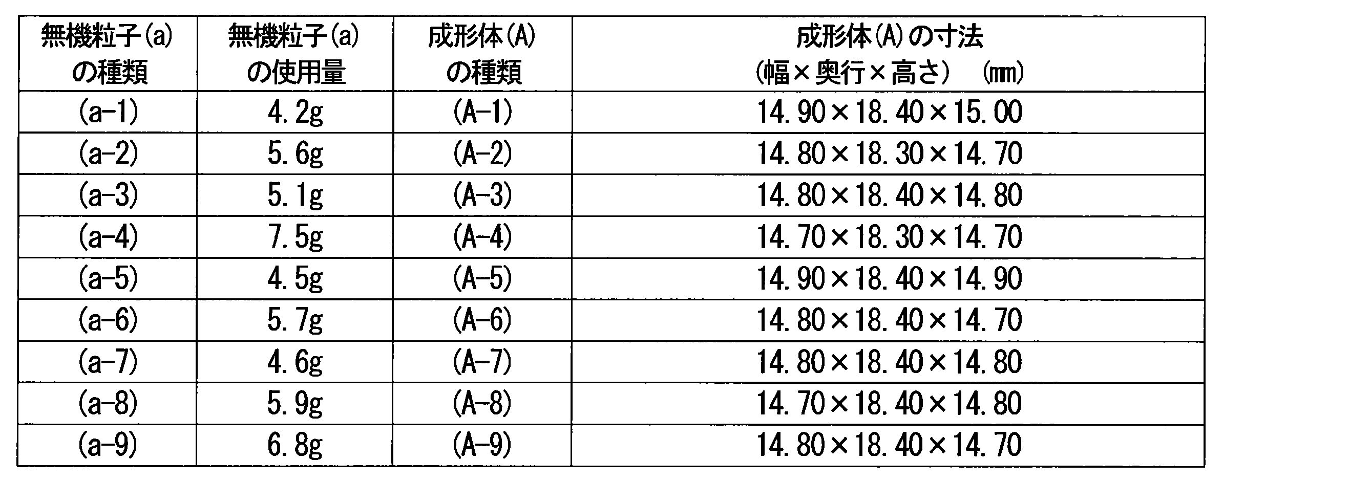
〔実施例1〕
テフロン製鋳型1(図2A)は、成形体(A-1)と略同一形状の収容空間を4つ有する。この鋳型1の1つの収容空間20の内寸は、幅14.92mm×奥行18.42mm×高さ15.00mmである。前記鋳型1の各収容空間20に、それぞれ成形体(A-1)を収容した。収容空間に成形体(A-1)を収容した鋳型1をポリエチレン製の袋体の内部に設置した。次いで、組成物(B-1)の溶液を袋体の内部に導入し、袋体内部を0.001kPa以下に減圧した条件下で、成形体(A-1)を室温で1日間静置して、成形体(A-1)に組成物(B-1)を含浸させた。その後、鋳型1の隙間W1に、組成物(B-1)が満たされていることを目視で確認した。次に、組成物(B-1)を含浸させた成形体(A-1)を、袋体に配置した状態で、熱風乾燥機を用いて、55℃18時間加熱後、さらに110℃3時間の加熱処理に供して、重合性単量体を重合させて、ミルブランク(C-1)を得た。ミルブランク(C-1)は、14.90mm×18.40mm×15.00mmの角柱状のミルブランク部と、周方向の4面に0.01mmの厚さを有するコーティング層とを備えていた。ミルブランク部、及びコーティング層の厚さは、カラー3Dレーザー顕微鏡(VK-9710、KEYENCE社製)を用いて測定した。観察写真の結果を図8に示す。
テフロン製鋳型1(図2A)は、成形体(A-1)と略同一形状の収容空間を4つ有する。この鋳型1の1つの収容空間20の内寸は、幅14.92mm×奥行18.42mm×高さ15.00mmである。前記鋳型1の各収容空間20に、それぞれ成形体(A-1)を収容した。収容空間に成形体(A-1)を収容した鋳型1をポリエチレン製の袋体の内部に設置した。次いで、組成物(B-1)の溶液を袋体の内部に導入し、袋体内部を0.001kPa以下に減圧した条件下で、成形体(A-1)を室温で1日間静置して、成形体(A-1)に組成物(B-1)を含浸させた。その後、鋳型1の隙間W1に、組成物(B-1)が満たされていることを目視で確認した。次に、組成物(B-1)を含浸させた成形体(A-1)を、袋体に配置した状態で、熱風乾燥機を用いて、55℃18時間加熱後、さらに110℃3時間の加熱処理に供して、重合性単量体を重合させて、ミルブランク(C-1)を得た。ミルブランク(C-1)は、14.90mm×18.40mm×15.00mmの角柱状のミルブランク部と、周方向の4面に0.01mmの厚さを有するコーティング層とを備えていた。ミルブランク部、及びコーティング層の厚さは、カラー3Dレーザー顕微鏡(VK-9710、KEYENCE社製)を用いて測定した。観察写真の結果を図8に示す。
〔実施例2〕
1つの収容空間20の内寸が幅15.50mm×奥行19.00mm×高さ15.00mmである以外は実施例1と同一の鋳型1の各収容空間20にそれぞれ成形体(A-1)を収容し、実施例1と同様にしてミルブランク(C-2)を作製した。ミルブランク(C-2)は、14.90mm×18.40mm×15.00mmの角柱状のミルブランク部と、周方向の4面に0.30mmの厚さを有するコーティング層とを備えていた。
1つの収容空間20の内寸が幅15.50mm×奥行19.00mm×高さ15.00mmである以外は実施例1と同一の鋳型1の各収容空間20にそれぞれ成形体(A-1)を収容し、実施例1と同様にしてミルブランク(C-2)を作製した。ミルブランク(C-2)は、14.90mm×18.40mm×15.00mmの角柱状のミルブランク部と、周方向の4面に0.30mmの厚さを有するコーティング層とを備えていた。
〔実施例3〕
1つの収容空間20の内寸が幅15.90mm×奥行19.40mm×高さ15.00mmである以外は実施例1と同一の鋳型1の各収容空間20にそれぞれ成形体(A-1)を収容し、実施例1と同様にしてミルブランク(C-3)を作製した。ミルブランク(C-3)は、14.90mm×18.40mm×15.00mmの角柱状のミルブランク部と、周方向の4面に0.50mmの厚さを有するコーティング層とを備えていた。
1つの収容空間20の内寸が幅15.90mm×奥行19.40mm×高さ15.00mmである以外は実施例1と同一の鋳型1の各収容空間20にそれぞれ成形体(A-1)を収容し、実施例1と同様にしてミルブランク(C-3)を作製した。ミルブランク(C-3)は、14.90mm×18.40mm×15.00mmの角柱状のミルブランク部と、周方向の4面に0.50mmの厚さを有するコーティング層とを備えていた。
〔実施例4〕
1つの収容空間20の内寸が幅15.50mm×奥行19.00mm×高さ15.00mmである以外は実施例1と同一の鋳型1の各収容空間20にそれぞれ成形体(A-1)を収容した。収容空間に成形体(A-1)を収容した鋳型1をポリエチレン製の袋体の内部に設置した。次いで、組成物(B-2)を袋体の内部に導入し、袋体内部を0.001kPa以下に減圧した条件下で、成形体(A-1)を室温で1日間静置して、成形体(A-1)に組成物(B-2)を含浸させた。その後、鋳型1の隙間W1に、組成物(B-2)が満たされていることを確認した。次に、組成物(B-2)を含浸させた成形体(A-1)を、袋体に配置した状態で、歯科重合用光照射器(ペンキュアー2000、モリタ社製)で1分間光照射した後に、さらに110℃3時間の加熱処理に供して、重合性単量体を重合させて、ミルブランク(C-4)を得た。ミルブランク(C-4)は、14.90mm×18.40mm×15.00mmの角柱状のミルブランク部と、周方向の4面に0.30mmの厚さを有するコーティング層とを備えていた。ミルブランク部及びコーティング層の厚さは、カラー3Dレーザー顕微鏡(VK-9710、KEYENCE社製)を用いて測定した。
1つの収容空間20の内寸が幅15.50mm×奥行19.00mm×高さ15.00mmである以外は実施例1と同一の鋳型1の各収容空間20にそれぞれ成形体(A-1)を収容した。収容空間に成形体(A-1)を収容した鋳型1をポリエチレン製の袋体の内部に設置した。次いで、組成物(B-2)を袋体の内部に導入し、袋体内部を0.001kPa以下に減圧した条件下で、成形体(A-1)を室温で1日間静置して、成形体(A-1)に組成物(B-2)を含浸させた。その後、鋳型1の隙間W1に、組成物(B-2)が満たされていることを確認した。次に、組成物(B-2)を含浸させた成形体(A-1)を、袋体に配置した状態で、歯科重合用光照射器(ペンキュアー2000、モリタ社製)で1分間光照射した後に、さらに110℃3時間の加熱処理に供して、重合性単量体を重合させて、ミルブランク(C-4)を得た。ミルブランク(C-4)は、14.90mm×18.40mm×15.00mmの角柱状のミルブランク部と、周方向の4面に0.30mmの厚さを有するコーティング層とを備えていた。ミルブランク部及びコーティング層の厚さは、カラー3Dレーザー顕微鏡(VK-9710、KEYENCE社製)を用いて測定した。
〔実施例5~12〕
実施例1と同様の方法にて、ミルブランク(C-5)~(C-12)を作製した。用いた成形体(A)及びテフロン製鋳型1(図2A)の収容空間20の内寸、形成されたコーティング層の厚さを下記表2に示した。なお、実施例11及び12においては、内表面がエンボス加工されたポリエチレン製の袋体を用いた。(C-11)および(C-12)においては、コーティング層は6面(周方向の4面及び、対向する上面と下面)の全面に形成されていた。
実施例1と同様の方法にて、ミルブランク(C-5)~(C-12)を作製した。用いた成形体(A)及びテフロン製鋳型1(図2A)の収容空間20の内寸、形成されたコーティング層の厚さを下記表2に示した。なお、実施例11及び12においては、内表面がエンボス加工されたポリエチレン製の袋体を用いた。(C-11)および(C-12)においては、コーティング層は6面(周方向の4面及び、対向する上面と下面)の全面に形成されていた。
〔比較例1〕
無機粒子(a-1)の30.0gを、35mm×25mmの長方形の穴を持つプレス用金型の下パンチ棒の上に敷いた。タッピングにより無機粒子(a-1)をならした後に、上パンチ棒を上にセットし、プレス機を用いて一軸プレス(プレス圧68.6MPa(60.0kN)、時間は1分間)を行った。上パンチ棒と下パンチ棒を金型から外して、該粉末が凝集したプレス成形体(A-10)を取り出した。該成形体の大きさは、35.00×25.00×20.00mmの角柱状であった。該プレス成形体(A-10)を、ポリエチレン製の袋体の内部に設置し、その後、組成物(B-1)を袋体の内部に導入し、袋体内部を0.001kPa以下に減圧した条件下で、成形体(A-10)を室温で3日間静置して、成形体(A-10)に組成物(B-1)を含浸させた。次いで、重合性単量体が含浸された該成形体を、熱風乾燥器を用いて55℃18時間加熱した後、さらに110℃3時間加熱処理を行って、重合性硬化物を得た。この重合性硬化物をダイヤモンドカッター(アイソメット1000、Buehler社製)を用いて切断することで、14.80mm×18.40mm×14.70mmの角柱状のミルブランクを得た。レーザー顕微鏡で確認すると、コーティング層は見られなかった。
無機粒子(a-1)の30.0gを、35mm×25mmの長方形の穴を持つプレス用金型の下パンチ棒の上に敷いた。タッピングにより無機粒子(a-1)をならした後に、上パンチ棒を上にセットし、プレス機を用いて一軸プレス(プレス圧68.6MPa(60.0kN)、時間は1分間)を行った。上パンチ棒と下パンチ棒を金型から外して、該粉末が凝集したプレス成形体(A-10)を取り出した。該成形体の大きさは、35.00×25.00×20.00mmの角柱状であった。該プレス成形体(A-10)を、ポリエチレン製の袋体の内部に設置し、その後、組成物(B-1)を袋体の内部に導入し、袋体内部を0.001kPa以下に減圧した条件下で、成形体(A-10)を室温で3日間静置して、成形体(A-10)に組成物(B-1)を含浸させた。次いで、重合性単量体が含浸された該成形体を、熱風乾燥器を用いて55℃18時間加熱した後、さらに110℃3時間加熱処理を行って、重合性硬化物を得た。この重合性硬化物をダイヤモンドカッター(アイソメット1000、Buehler社製)を用いて切断することで、14.80mm×18.40mm×14.70mmの角柱状のミルブランクを得た。レーザー顕微鏡で確認すると、コーティング層は見られなかった。
試験1(シャルピー衝撃試験)
得られたミルブランクの耐衝撃性評価をシャルピー衝撃試験機(株式会社ナビック製;アーム長105mm、アーム重量300g)を用いて、以下の方法により行った。300gの振り子バーに3mmφのSUSチップを取り付け、作製したミルブランクと、3mmφSUSチップの半分の面積が接触するようにセットした。バーの位置を150°にセットし、ミルブランクへ衝突させる動作を続けて3回繰り返した際に、ミルブランクに欠け、又は1mm以上の傷(割れ)が目視で確認できた場合、破損したと判断した。試験結果を下記表2に示す。
得られたミルブランクの耐衝撃性評価をシャルピー衝撃試験機(株式会社ナビック製;アーム長105mm、アーム重量300g)を用いて、以下の方法により行った。300gの振り子バーに3mmφのSUSチップを取り付け、作製したミルブランクと、3mmφSUSチップの半分の面積が接触するようにセットした。バーの位置を150°にセットし、ミルブランクへ衝突させる動作を続けて3回繰り返した際に、ミルブランクに欠け、又は1mm以上の傷(割れ)が目視で確認できた場合、破損したと判断した。試験結果を下記表2に示す。
試験2(バレル研磨)
得られたミルブランクの耐衝撃性評価を遠心バレル研磨機(縦型遠心バレル、型式:HS-1-4V、株式会社チップトン製)を用いて、以下の方法により行った。
バレル槽に、研磨石1.5kg、水600mL、バレル研磨用液体コンパウンド(LC-NZ-NP、株式会社チップトン製)5mLを入れ、作製したミルブランクを入れた。バレル槽をバレルケースに装入し、45分間の研磨を行った後、ミルブランクに欠け、又は1mm以上の傷(割れ)が目視で確認できた場合、破損したと判断した。試験結果を下記表2に示す。
得られたミルブランクの耐衝撃性評価を遠心バレル研磨機(縦型遠心バレル、型式:HS-1-4V、株式会社チップトン製)を用いて、以下の方法により行った。
バレル槽に、研磨石1.5kg、水600mL、バレル研磨用液体コンパウンド(LC-NZ-NP、株式会社チップトン製)5mLを入れ、作製したミルブランクを入れた。バレル槽をバレルケースに装入し、45分間の研磨を行った後、ミルブランクに欠け、又は1mm以上の傷(割れ)が目視で確認できた場合、破損したと判断した。試験結果を下記表2に示す。
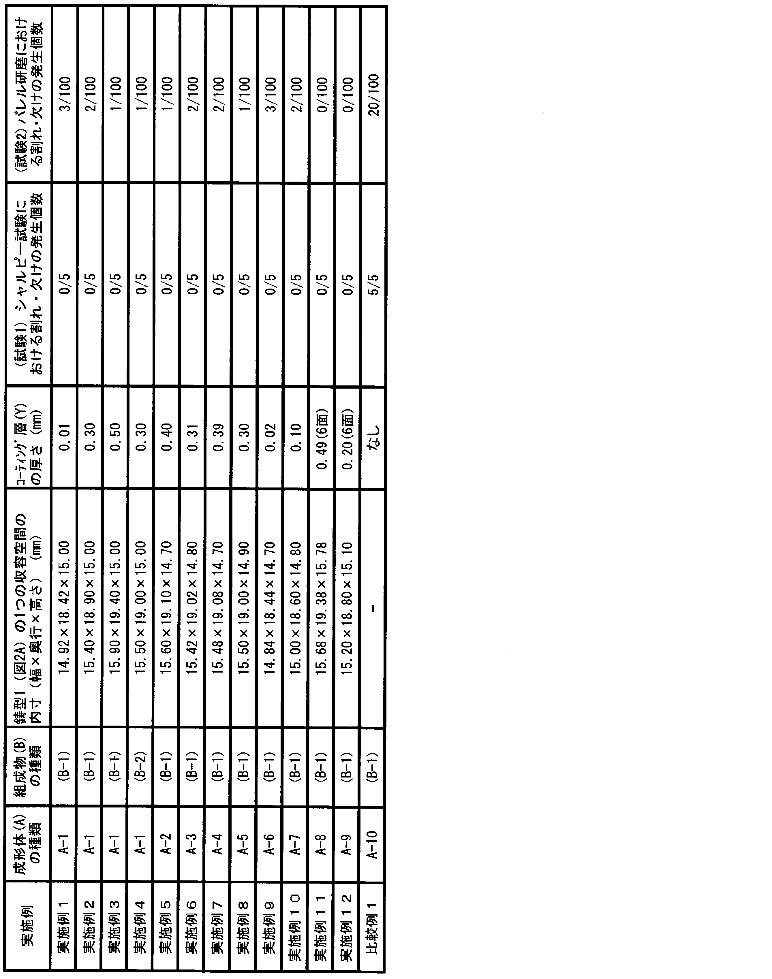
衝撃試験(シャルピー衝撃試験)において、コーティング層を有しないミルブランク(比較例1)では、ひび割れあるいは欠けが生じた(5/5)。これに対して、周方向のすべての面を覆うコーティング層を有するミルブランク(実施例1~12)では生じなかった(0/5)。また、バレル研磨においても、コーティング層を有しないミルブランク(比較例1)と比べ、周方向のすべての面を覆うコーティング層を有するミルブランク(実施例1~12)では割れ、欠けによる不合格数が大幅に減少した。
本発明のミルブランクは、製造における歩留まりを向上させるため、有用である。特に、本発明のミルブランクは、バレル研磨時の耐衝撃性に優れる。
1,2,3,4 鋳型
100 成形体(A)
101 底面
102 上面
103 側面
110 組成物(B)
120 鋳型収容容器
20 収容空間
201 隙間
300 歯科用ミルブランク
310 ミルブランク部(X)
320 コーティング層(Y)
100 成形体(A)
101 底面
102 上面
103 側面
110 組成物(B)
120 鋳型収容容器
20 収容空間
201 隙間
300 歯科用ミルブランク
310 ミルブランク部(X)
320 コーティング層(Y)
Claims (12)
- ミルブランク部(X)と、前記ミルブランク部(X)の少なくとも周方向のすべての面を被覆するコーティング層(Y)とを備え、
前記ミルブランク部(X)が無機充填材と重合性単量体(b)の硬化物とを含有し、
前記コーティング層(Y)が無機充填材を実質的に含まず重合性単量体(b)の硬化物を含有し、
角柱状である歯科用ミルブランク。 - コーティング層(Y)の厚さが、0.01~0.60mmである、請求項1に記載の歯科用ミルブランク。
- 角柱状が、直方体状又は立方体状である、請求項1又は2に記載の歯科用ミルブランク。
- 無機充填材が、平均粒子径が1.0nm~20μmである無機粒子(a)を含む、請求項1~3のいずれか1項に記載の歯科用ミルブランク。
- 無機粒子(a)の平均粒子径が2.0nm~10μmである、請求項1~4のいずれか1項に記載の歯科用ミルブランク。
- 重合性単量体(b)が、二官能性(メタ)アクリレートを含む、請求項1~5のいずれか1項に記載の歯科用ミルブランク。
- コーティング層(Y)の厚さが、0.10~0.50mmである、請求項1~6のいずれか1項に記載の歯科用ミルブランク。
- 鋳型内において、角柱状である無機充填材の成形体(A)と重合性単量体(b)を含む重合性単量体含有組成物(B)とを接触させる工程(I)、
前記鋳型内において、組成物(B)に含まれる重合性単量体(b)を重合させる工程(II)を有し、
前記鋳型は、重合性単量体(b)の硬化物であるコーティング層(Y)が少なくとも角柱状の成形体(A)の周方向のすべての面を被覆できるように、成形体(A)を収容する収容空間を備え、
前記収容空間は、少なくとも周方向のすべての面において、収容された成形体(A)の端面と鋳型の収容空間の内壁面との間に隙間を有するサイズである、
請求項1~7のいずれか1項に記載された歯科用ミルブランクの製造方法。 - 隙間が、0.01~0.60mmである、請求項8に記載の歯科用ミルブランクの製造方法。
- 角柱状である無機充填材の成形体(A)と重合性単量体(b)を含む重合性単量体含有組成物(B)との接触工程(I)を減圧下に行う、請求項8又は9に記載の歯科用ミルブランクの製造方法。
- 減圧下における角柱状である無機充填材の成形体(A)と重合性単量体(b)を含む重合性単量体含有組成物(B)との接触工程(I)が、12~48時間である、請求項10に記載の歯科用ミルブランクの製造方法。
- 重合性単量体(b)を重合させる工程(II)の後に、さらに80~150℃で加熱処理を行う、請求項8~11のいずれか1項に記載の歯科用ミルブランクの製造方法。
Priority Applications (1)
| Application Number | Priority Date | Filing Date | Title |
|---|---|---|---|
| JP2018504481A JPWO2017154850A1 (ja) | 2016-03-07 | 2017-03-06 | 歯科用ミルブランク及びその製造方法 |
Applications Claiming Priority (2)
| Application Number | Priority Date | Filing Date | Title |
|---|---|---|---|
| JP2016043847 | 2016-03-07 | ||
| JP2016-043847 | 2016-03-07 |
Publications (1)
| Publication Number | Publication Date |
|---|---|
| WO2017154850A1 true WO2017154850A1 (ja) | 2017-09-14 |
Family
ID=59789441
Family Applications (1)
| Application Number | Title | Priority Date | Filing Date |
|---|---|---|---|
| PCT/JP2017/008841 Ceased WO2017154850A1 (ja) | 2016-03-07 | 2017-03-06 | 歯科用ミルブランク及びその製造方法 |
Country Status (2)
| Country | Link |
|---|---|
| JP (1) | JPWO2017154850A1 (ja) |
| WO (1) | WO2017154850A1 (ja) |
Cited By (9)
| Publication number | Priority date | Publication date | Assignee | Title |
|---|---|---|---|---|
| JP2018089312A (ja) * | 2016-12-07 | 2018-06-14 | クラレノリタケデンタル株式会社 | 歯科用補綴物 |
| WO2019054507A1 (ja) * | 2017-09-14 | 2019-03-21 | 株式会社トクヤマデンタル | 歯科用硬化性組成物 |
| WO2019065777A1 (ja) * | 2017-09-26 | 2019-04-04 | クラレノリタケデンタル株式会社 | 歯科用ミルブランクおよびその製造方法 |
| JP2019098074A (ja) * | 2017-12-07 | 2019-06-24 | クラレノリタケデンタル株式会社 | 歯科用ミルブランクの製造方法 |
| JP2019098073A (ja) * | 2017-12-07 | 2019-06-24 | クラレノリタケデンタル株式会社 | 歯科用ミルブランクの製造方法 |
| WO2019131756A1 (ja) * | 2017-12-26 | 2019-07-04 | クラレノリタケデンタル株式会社 | 歯科用ミルブランクおよびその製造方法 |
| JP2019116430A (ja) * | 2017-12-26 | 2019-07-18 | クラレノリタケデンタル株式会社 | 歯科用ミルブランク |
| JP2020151235A (ja) * | 2019-03-20 | 2020-09-24 | クラレノリタケデンタル株式会社 | ジルコニアミルブランク及びその製造方法 |
| KR102756773B1 (ko) * | 2024-06-24 | 2025-01-21 | 주식회사 이노메디 | 치과용 수지 블록의 제조방법 및 치과용 수지 블록 |
Citations (3)
| Publication number | Priority date | Publication date | Assignee | Title |
|---|---|---|---|---|
| WO2009154301A1 (ja) * | 2008-06-18 | 2009-12-23 | 株式会社アドバンス | 歯科補綴物加工用ブロック及びその製造方法 |
| JP2012087204A (ja) * | 2010-10-19 | 2012-05-10 | Panasonic Corp | 樹脂硬化物、硬化性組成物、及び樹脂硬化物の製造方法 |
| WO2014021343A1 (ja) * | 2012-07-31 | 2014-02-06 | クラレノリタケデンタル株式会社 | 歯科用ミルブランクの製造方法 |
-
2017
- 2017-03-06 JP JP2018504481A patent/JPWO2017154850A1/ja active Pending
- 2017-03-06 WO PCT/JP2017/008841 patent/WO2017154850A1/ja not_active Ceased
Patent Citations (3)
| Publication number | Priority date | Publication date | Assignee | Title |
|---|---|---|---|---|
| WO2009154301A1 (ja) * | 2008-06-18 | 2009-12-23 | 株式会社アドバンス | 歯科補綴物加工用ブロック及びその製造方法 |
| JP2012087204A (ja) * | 2010-10-19 | 2012-05-10 | Panasonic Corp | 樹脂硬化物、硬化性組成物、及び樹脂硬化物の製造方法 |
| WO2014021343A1 (ja) * | 2012-07-31 | 2014-02-06 | クラレノリタケデンタル株式会社 | 歯科用ミルブランクの製造方法 |
Cited By (26)
| Publication number | Priority date | Publication date | Assignee | Title |
|---|---|---|---|---|
| JP2018089312A (ja) * | 2016-12-07 | 2018-06-14 | クラレノリタケデンタル株式会社 | 歯科用補綴物 |
| US11452675B2 (en) | 2017-09-14 | 2022-09-27 | Tokuyama Dental Corporation | Dental curable composition |
| KR102575314B1 (ko) | 2017-09-14 | 2023-09-06 | 가부시키가이샤 도쿠야마 덴탈 | 치과용 경화성 조성물 |
| WO2019054507A1 (ja) * | 2017-09-14 | 2019-03-21 | 株式会社トクヤマデンタル | 歯科用硬化性組成物 |
| KR20200054187A (ko) * | 2017-09-14 | 2020-05-19 | 가부시키가이샤 도쿠야마 덴탈 | 치과용 경화성 조성물 |
| WO2019065777A1 (ja) * | 2017-09-26 | 2019-04-04 | クラレノリタケデンタル株式会社 | 歯科用ミルブランクおよびその製造方法 |
| CN111093559A (zh) * | 2017-09-26 | 2020-05-01 | 可乐丽则武齿科株式会社 | 牙科用研磨坯料和其制造方法 |
| JP7077329B2 (ja) | 2017-09-26 | 2022-05-30 | クラレノリタケデンタル株式会社 | 歯科用ミルブランクおよびその製造方法 |
| JPWO2019065777A1 (ja) * | 2017-09-26 | 2020-10-22 | クラレノリタケデンタル株式会社 | 歯科用ミルブランクおよびその製造方法 |
| JP2022119841A (ja) * | 2017-09-26 | 2022-08-17 | クラレノリタケデンタル株式会社 | 歯科用ミルブランクおよびその製造方法 |
| CN111093559B (zh) * | 2017-09-26 | 2022-07-12 | 可乐丽则武齿科株式会社 | 牙科用研磨坯料和其制造方法 |
| EP3689291A4 (en) * | 2017-09-26 | 2021-06-02 | Kuraray Noritake Dental Inc. | DENTAL MILLING BLANK AND METHOD FOR ITS MANUFACTURING |
| JP2019098074A (ja) * | 2017-12-07 | 2019-06-24 | クラレノリタケデンタル株式会社 | 歯科用ミルブランクの製造方法 |
| JP2019098073A (ja) * | 2017-12-07 | 2019-06-24 | クラレノリタケデンタル株式会社 | 歯科用ミルブランクの製造方法 |
| JP2019116430A (ja) * | 2017-12-26 | 2019-07-18 | クラレノリタケデンタル株式会社 | 歯科用ミルブランク |
| JP7061826B2 (ja) | 2017-12-26 | 2022-05-02 | クラレノリタケデンタル株式会社 | 歯科用ミルブランク |
| EP3733114A4 (en) * | 2017-12-26 | 2021-08-04 | Kuraray Noritake Dental Inc. | DENTAL MILLING BLANK AND METHOD FOR ITS MANUFACTURING |
| JPWO2019131756A1 (ja) * | 2017-12-26 | 2021-01-14 | クラレノリタケデンタル株式会社 | 歯科用ミルブランクおよびその製造方法 |
| US20200360120A1 (en) * | 2017-12-26 | 2020-11-19 | Kuraray Noritake Dental Inc. | Dental mill blank and method for producing same |
| US11707346B2 (en) | 2017-12-26 | 2023-07-25 | Kuraray Noritake Dental Inc. | Dental mill blank and method for producing same |
| JP7315474B2 (ja) | 2017-12-26 | 2023-07-26 | クラレノリタケデンタル株式会社 | 歯科用ミルブランクおよびその製造方法 |
| WO2019131756A1 (ja) * | 2017-12-26 | 2019-07-04 | クラレノリタケデンタル株式会社 | 歯科用ミルブランクおよびその製造方法 |
| JP2020151235A (ja) * | 2019-03-20 | 2020-09-24 | クラレノリタケデンタル株式会社 | ジルコニアミルブランク及びその製造方法 |
| JP7189817B2 (ja) | 2019-03-20 | 2022-12-14 | クラレノリタケデンタル株式会社 | ジルコニアミルブランク及びその製造方法 |
| KR102756773B1 (ko) * | 2024-06-24 | 2025-01-21 | 주식회사 이노메디 | 치과용 수지 블록의 제조방법 및 치과용 수지 블록 |
| WO2026005256A1 (ko) * | 2024-06-24 | 2026-01-02 | 주식회사 이노메디 | 치과용 수지 블록의 제조방법 및 치과용 수지 블록 |
Also Published As
| Publication number | Publication date |
|---|---|
| JPWO2017154850A1 (ja) | 2019-01-10 |
Similar Documents
| Publication | Publication Date | Title |
|---|---|---|
| JP6170922B2 (ja) | 歯科用ミルブランクの製造方法 | |
| US11707346B2 (en) | Dental mill blank and method for producing same | |
| JP6571511B2 (ja) | 歯科用ミルブランクの製造方法及びその製造方法により得られた歯科用ミルブランク | |
| JPWO2017154850A1 (ja) | 歯科用ミルブランク及びその製造方法 | |
| JP6930993B2 (ja) | 複数色積層歯科用ミルブランク | |
| JP6929014B2 (ja) | 歯科用ミルブランクの製造方法 | |
| JP2022119841A (ja) | 歯科用ミルブランクおよびその製造方法 | |
| JP7061826B2 (ja) | 歯科用ミルブランク | |
| JP6806547B2 (ja) | 歯科用硬化性組成物 | |
| JP7357005B2 (ja) | 色調最適化された歯科用ミルブランク | |
| JP2019098073A (ja) | 歯科用ミルブランクの製造方法 | |
| JP7676322B2 (ja) | 歯科用ミルブランク | |
| JP7503464B2 (ja) | 歯科用ミルブランク製造用の容器、及び歯科用ミルブランクの製造方法 | |
| EP3556814A1 (en) | Method for producing surface-treated colored inorganic particles | |
| JP2019098074A (ja) | 歯科用ミルブランクの製造方法 | |
| JP7125260B2 (ja) | 歯科用ミルブランク製造用の無機充填材複合体 | |
| JP2020068871A (ja) | クラウンコア一体型歯科用ミルブランク |
Legal Events
| Date | Code | Title | Description |
|---|---|---|---|
| WWE | Wipo information: entry into national phase |
Ref document number: 2018504481 Country of ref document: JP |
|
| NENP | Non-entry into the national phase |
Ref country code: DE |
|
| 121 | Ep: the epo has been informed by wipo that ep was designated in this application |
Ref document number: 17763190 Country of ref document: EP Kind code of ref document: A1 |
|
| 122 | Ep: pct application non-entry in european phase |
Ref document number: 17763190 Country of ref document: EP Kind code of ref document: A1 |