WO2017154323A1 - 小型油圧ショベル - Google Patents
小型油圧ショベル Download PDFInfo
- Publication number
- WO2017154323A1 WO2017154323A1 PCT/JP2017/000179 JP2017000179W WO2017154323A1 WO 2017154323 A1 WO2017154323 A1 WO 2017154323A1 JP 2017000179 W JP2017000179 W JP 2017000179W WO 2017154323 A1 WO2017154323 A1 WO 2017154323A1
- Authority
- WO
- WIPO (PCT)
- Prior art keywords
- level gauge
- hydraulic oil
- oil tank
- cab
- revolving
- Prior art date
- Legal status (The legal status is an assumption and is not a legal conclusion. Google has not performed a legal analysis and makes no representation as to the accuracy of the status listed.)
- Ceased
Links
Images


Classifications
-
- E—FIXED CONSTRUCTIONS
- E02—HYDRAULIC ENGINEERING; FOUNDATIONS; SOIL SHIFTING
- E02F—DREDGING; SOIL-SHIFTING
- E02F9/00—Component parts of dredgers or soil-shifting machines, not restricted to one of the kinds covered by groups E02F3/00 - E02F7/00
-
- E—FIXED CONSTRUCTIONS
- E02—HYDRAULIC ENGINEERING; FOUNDATIONS; SOIL SHIFTING
- E02F—DREDGING; SOIL-SHIFTING
- E02F3/00—Dredgers; Soil-shifting machines
- E02F3/04—Dredgers; Soil-shifting machines mechanically-driven
- E02F3/28—Dredgers; Soil-shifting machines mechanically-driven with digging tools mounted on a dipper- or bucket-arm, i.e. there is either one arm or a pair of arms, e.g. dippers, buckets
- E02F3/30—Dredgers; Soil-shifting machines mechanically-driven with digging tools mounted on a dipper- or bucket-arm, i.e. there is either one arm or a pair of arms, e.g. dippers, buckets with a dipper-arm pivoted on a cantilever beam, i.e. boom
- E02F3/32—Dredgers; Soil-shifting machines mechanically-driven with digging tools mounted on a dipper- or bucket-arm, i.e. there is either one arm or a pair of arms, e.g. dippers, buckets with a dipper-arm pivoted on a cantilever beam, i.e. boom working downwardly and towards the machine, e.g. with backhoes
- E02F3/325—Backhoes of the miniature type
-
- E—FIXED CONSTRUCTIONS
- E02—HYDRAULIC ENGINEERING; FOUNDATIONS; SOIL SHIFTING
- E02F—DREDGING; SOIL-SHIFTING
- E02F9/00—Component parts of dredgers or soil-shifting machines, not restricted to one of the kinds covered by groups E02F3/00 - E02F7/00
- E02F9/08—Superstructures; Supports for superstructures
- E02F9/0858—Arrangement of component parts installed on superstructures not otherwise provided for, e.g. electric components, fenders, air-conditioning units
- E02F9/0883—Tanks, e.g. oil tank, urea tank, fuel tank
-
- G—PHYSICS
- G01—MEASURING; TESTING
- G01F—MEASURING VOLUME, VOLUME FLOW, MASS FLOW OR LIQUID LEVEL; METERING BY VOLUME
- G01F23/00—Indicating or measuring liquid level or level of fluent solid material, e.g. indicating in terms of volume or indicating by means of an alarm
- G01F23/02—Indicating or measuring liquid level or level of fluent solid material, e.g. indicating in terms of volume or indicating by means of an alarm by gauge glasses or other apparatus involving a window or transparent tube for directly observing the level to be measured or the level of a liquid column in free communication with the main body of the liquid
Definitions
- the present invention operates at a work site such as a building or a narrow residential area, and has a crawler type traveling device in a vehicle width that can correspond to a narrow road during movement, and is mounted on the traveling body on the traveling body.
- the present invention relates to a small-sized hydraulic excavator in which the arrangement area of various devices and members arranged in the revolving structure is narrow, and particularly restricted by the arrangement of the hydraulic oil tank.
- Patent Document 1 This type of prior art is disclosed in Patent Document 1.
- a traveling body which is operated in a work site such as a building or a narrow residential area and has a crawler type traveling device in a vehicle width which can correspond to a narrow road at the time of movement, and can turn on the traveling body. Since the width of the swivel mounted with the cab is limited, the area of equipment and members arranged in the swivel is narrow, and it is said to be a mini excavator that is particularly restricted by the placement of the hydraulic oil tank A small hydraulic excavator is disclosed.
- This prior art includes a traveling body provided with a pair of left and right crawler type traveling devices, a revolving body disposed on the traveling body so as to be able to swivel, and a front end frame protruding forward from the revolving frame of the revolving body.
- a working device (consisting of a boom, an arm, a bucket, a boom cylinder, an arm cylinder, a bucket linder, etc.) mounted so as to be able to rotate in the vertical direction with respect to the arranged swing post for swinging left and right. I have.
- a cab (operator's cab) is arranged from the front end side of the revolving frame to the rear side beyond the revolving center, and the width in the left-right direction of the cab (the left and right side surfaces of the cab) is The width is the same as or close to the width of the traveling body provided with the pair of left and right crawler type traveling devices.
- tanks such as a hydraulic oil tank and a fuel tank and a switching valve group composed of a plurality of directional switching valves are arranged.
- a heat exchanger including a hydraulic pump, a radiator, an oil cooler, and the like are arranged.
- a counterweight having an arcuate outer peripheral side for balancing with the working device is disposed.
- the swivel frame behind the cab covers from the center of the cab to the counterweight to surround the tanks such as the hydraulic oil tank and fuel tank, and the heat exchanger composed of the engine, hydraulic pump, radiator and oil cooler, etc. A cover is installed.
- This exterior cover is arranged from the right and left sides of the cab to the rear side, and the left and right side surfaces thereof are the same as or similar to the width of the traveling body provided with the pair of left and right crawler type traveling devices like the left and right side surfaces of the cab. It has become a width.
- a partition plate that forms an engine room together with the exterior cover is arranged in a continuous form from the floor located in front of the cab The driver's seat is placed on the partition plate.
- the hydraulic oil tank is located below the partition plate in the cab, is placed on the revolving frame of the revolving body, and is disposed with a predetermined clearance from the exterior cover. The hydraulic fluid supplied to each actuator of the hydraulic drive system to drive is accommodated.
- the hydraulic oil tank In the hydraulic oil tank, the hydraulic oil tank is placed so as to face a confirmation hole formed on one side of the left and right side surfaces of the exterior cover (for example, a position opposite to the entrance door on the one side surface of the cab).
- a level gauge is provided which defines the amount of hydraulic oil to be accommodated and is hollow inside. This level gauge is provided on the side surface of the projecting portion located on the exterior cover side, and a circular projecting portion projecting from the side surface of the hydraulic oil tank in consideration of securing a large capacity of the hydraulic oil tank. And a window formed by a transparent member that enables visual confirmation of the oil level of the hydraulic oil inside the hydraulic oil tank through a confirmation hole formed in the exterior cover.
- Small hydraulic excavators such as the above-mentioned mini excavator are limited in the width of the traveling body and the revolving body so as to be suitable for confined work, thereby being in the cab on the revolving frame constituting the revolving body, It is possible that the level gauge window slightly protrudes from the confirmation hole of the outer cover due to an error during assembly caused by assembling many parts and members in a limited narrow area.
- the small excavator assembled in this way the amount of hydraulic oil in the hydraulic oil tank can be easily confirmed, but when working in adjacent residential areas, etc. There is a concern that an external force is applied to the window of the level gauge by touching and the level gauge is damaged.
- an object of the present invention is to provide a small hydraulic excavator that can suppress an external force generated during work from acting on a level gauge provided in a hydraulic oil tank.
- a small hydraulic excavator includes a traveling body, a revolving body disposed on the traveling body, and a front end frame protruding forward from the revolving frame of the revolving body.
- a working device mounted so as to be able to rotate in the vertical direction with respect to the arranged swing post for swinging left and right, and on the revolving frame of the revolving body, beyond the revolving center from the front end side of the revolving frame
- a cab arranged to the rear side and having a width in the left-right direction along the width of the traveling body, and a swivel frame behind the cab arranged from the vicinity of the center of the cab to the rear end of the revolving body.
- a level gauge that is provided in the oil tank, defines an amount of hydraulic oil that is accommodated in the hydraulic oil tank, and has a hollow inside; and the level gauge projects from a side surface of the hydraulic oil tank; A window that is provided on a side surface of the projecting portion located on the exterior cover side and that allows visual confirmation of the oil level of the hydraulic oil inside the hydraulic oil tank through the confirmation hole formed in the exterior cover.
- a small hydraulic excavator having an attachment member to which the level gauge is attached, the attachment member being fixed to the side surface of the hydraulic oil tank, and the level gauge A shape surrounding the periphery of the protruding portion and smaller than the confirmation hole formed in the exterior cover, and an end surface of the attachment member located on the exterior cover side is the protrusion of the level gauge.
- the mounting member is provided so as to be flush with the side surface of the portion or from the side surface of the protruding portion of the level gauge.
- the mounting member fixed to the side surface of the hydraulic oil tank and to which the level gauge is attached is formed in a shape surrounding the periphery of the protruding portion of the level gauge, and the end surface of the mounting member is
- the mounting member since it is provided so as to be flush with the side surface of the protruding portion of the level gauge or from the side surface of the protruding portion of the level gauge, the external force generated during the operation is received by the mounting member. It can suppress acting on a level gauge.
- the present invention can realize protection with higher accuracy of the level gauge than the conventional one, and can be a highly reliable compact hydraulic excavator.
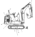
- FIG. 1 is a side view showing an embodiment of a small hydraulic excavator according to the present invention. It is a side view of this embodiment shown except a cab. It is a top view of this embodiment shown except a cab. It is a side view which shows the hydraulic oil tank with which this embodiment was equipped. It is a principal part expansion perspective view which shows the positional relationship of the attachment member and level gauge provided in the hydraulic oil tank shown in FIG. 4, and the confirmation hole of an exterior cover. It is a principal part expanded side view which shows the positional relationship of the attachment member provided in the hydraulic oil tank shown in FIG. 4, and an exterior cover. It is the figure which cut
- a small hydraulic excavator according to this embodiment includes a traveling body 1 having a pair of left and right crawler type traveling devices 1a, and the traveling body.
- the traveling body 1 having a pair of left and right crawler type traveling devices 1a, and the traveling body.
- the swivel body 2 arranged so as to be able to swivel on 1 and the swing post 2c for swinging left and right disposed on the front end frame 2b protruding forward from the swivel frame 2a of the swivel body 2 in the vertical direction.
- a working device 3 including a boom, an arm, a bucket, a boom cylinder, an arm cylinder, a bucket linder, etc. 3 that is attached so as to be able to rotate.
- a cab (operator's cab) 13 is disposed on the revolving frame 2a of the revolving structure 2 from the front end side of the revolving frame 2a to the rear side beyond the revolving center. 13a and the right side surface 13b) have the same width as the width of the traveling body 1 provided with the pair of left and right crawler type traveling devices 1a described above, or a width similar to the width, that is, a width shape along the width of the traveling body 1. ing. As shown in FIG.
- a plurality of tanks such as a hydraulic oil tank 5 and a fuel tank 6 are arranged from the vicinity of the center of the swivel frame 2 a in the cab 13 (near the center joint 6 d) to the rear side (near the engine 14 described later).
- a switching valve group 6a composed of directional switching valves is disposed, and an engine 14, a hydraulic pump 6b, a heat exchanger 6c composed of a radiator, an oil cooler, and the like are disposed on the rear side of each device.
- a counterweight 6e having an arcuate outer peripheral side for balancing with the work device 3 is disposed.
- the swivel frame 2a behind the cab 13 includes a hydraulic oil tank 5, tanks such as a fuel tank 6, an engine 14, a hydraulic pump 6b, a radiator, an oil cooler, and the like from near the center of the cab 13 to a counterweight 6e.
- An exterior cover 4 is attached so as to surround the heat exchanger 6c.
- the exterior cover 4 is disposed from the left and right sides to the rear side of the cab 13, and the left and right side surfaces of the cab 13 are provided with a pair of left and right crawler type traveling devices 1 a like the left side surface 13 a and the right side surface 13 b of the cab 13.
- the width is the same as or close to the width.
- a partition plate (not shown) that forms an engine room together with the exterior cover 4 is located in front of the cab 13 above the heat exchanger 6c including the engine 14, the hydraulic pump 6b, the radiator and the oil cooler in the cab 13. It arrange
- the hydraulic oil tank 5 is placed on the revolving frame 2a of the revolving structure 2 at a position below the partition plate in the cab 13 and along the right side surface side of the external cover 4, and the hydraulic oil tank 5 It is arranged with clearance.
- the hydraulic oil tank 5 stores hydraulic oil supplied to each actuator of a hydraulic drive system that drives the traveling body 1, the revolving body 2, and the work device 3.
- the swivel body 2, the cab 13, and the exterior cover 4 have a width dimension between the outer portions 1 a 1 of the traveling body 1 including a pair of left and right crawler type traveling devices 1 a.
- the engine 14, the hydraulic pump 6 b, and the radiator described above are formed in the engine room formed by the partition plate on which the driver's seat 12 is placed so as to correspond to the limited space for arranging the parts in the cab 13 and the exterior cover 4.
- a heat exchanger 6c made of an oil cooler or the like.
- the small hydraulic excavator has one end portion, that is, a front end when the pair of left and right crawler type traveling devices 1 a constituting the traveling body 1 is viewed from directly above the cab 13.
- the part protrudes from the cab 13 and the swing post 2c and is disposed up to the front position thereof.
- the maximum grounding fulcrum of the pair of left and right crawler type traveling devices 1a for supporting the load applied to the traveling body 1 through the swing post 2c and the revolving frame 2a of the revolving body 2 during work by the working device 3 is from the cab 13 and the swing post 2c. It becomes a front position, and work can be performed stably.
- the other end, that is, the rear end is disposed below the counterweight 6e on the revolving frame 2a.
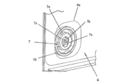
- the hydraulic oil tank 5 provided on the swivel frame 2a is attached to a suction port 5c1 formed so as to protrude upward from the upper surface side thereof, and is opened when the hydraulic oil is accommodated.
- a suction port 5c1 formed so as to protrude upward from the upper surface side thereof, and is opened when the hydraulic oil is accommodated.
- the right side surface 13b opposite to the entrance door (not shown) disposed on the left side surface 13a of the cab 13 is provided.
- a level gauge 7 having a hollow inside is disposed so as to face the formed confirmation hole 4a.
- the level gauge 7 has a circular shape protruding from the side surface 5a of the hydraulic oil tank 5 in consideration of securing a large capacity of the hydraulic oil tank 5 that is easily restricted by the shape and size because the arrangement space is limited.
- the oil level height of the working oil in the working oil tank 5 is provided on the projecting part 7a and a side surface 7e of the projecting part 7a located on the exterior cover 4 side, and is formed in the rectangular confirmation hole 4a formed in the exterior cover 4. It is made of a transparent member so that it can be visually confirmed, and has a round window 7b having a star-shaped portion inside.
- a circular mark 7c that defines the amount of hydraulic oil stored in the hydraulic oil tank 5 is formed.
- this small hydraulic excavator for example, if the actuator is a single rod cylinder, there will be a difference between the supply amount and the return amount).
- the hydraulic oil can be supplied to each actuator and the return oil from each actuator can be accommodated without the occurrence of such a difference.
- the small hydraulic excavator according to the present embodiment is fixed to the side surface 5 a of the hydraulic oil tank 5 and has a cylindrical shape surrounding the protrusion 7 a of the level gauge 7.
- the mounting member 10 is formed in a small shape so as to be included in the opening range of the confirmation hole 4 a formed in the exterior cover 4 and to which the level gauge 7 is attached.
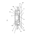
- the mounting member 10 has a double circular end face 10a1 located on the exterior cover 4 side, and is provided with an annular part 10a that contacts the side face 5a of the hydraulic oil tank 5 and surrounds the protruding part 7a of the level gauge 7. .
- the attachment member 10 is connected to the annular portion 10 a and is set to have an outer diameter smaller than the outer diameter of the annular portion 10 a and is inserted into an insertion hole 5 b formed in the hydraulic oil tank 5.
- a holding portion 10b having a through hole 10b1 in which a screw portion 10b2 is formed and holding the level gauge 7 is provided.
- the attachment member 10 is welded to the side surface 5a of the hydraulic oil tank 5 in a state where the holding portion 10b is inserted into the insertion hole 5b of the hydraulic oil tank 5 and the annular portion 10a is in contact with the side surface 5a of the hydraulic oil tank 5. It is fixed via the part.
- the level gauge 7 is inserted into the above-described protruding portion 7a that contacts the holding portion 10b of the mounting member 10 and a through hole 10b1 that is connected to the protruding portion 7a and formed in the holding portion 10b of the mounting member 10. And a cylindrical insertion portion 7d having a screw portion 7d1 screwed with the screw portion 10b2 of the through hole 10b1 of the holding portion 10b on the outer periphery.
- the insertion portion 7d of the level gauge 7 is screwed and attached to the holding portion 10b of the attachment member 10 by rotating.
- the window 7b provided on the protruding portion 7a of the level gauge 7 is as described above. Since a round shape having a star-shaped portion inside is formed, even if the level gauge 7 is attached to the attachment member 10 at any rotation angle, the uncomfortable appearance on the window 7b can be suppressed.
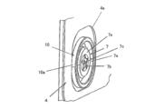
- the position of the mounting surface 11 of the level gauge 7 that forms a contact surface between the holding portion 10 b of the mounting member 10 and the protruding portion 7 a of the level gauge 7 is determined from the side surface 5 a of the hydraulic oil tank 5. Is also set inside the hydraulic oil tank 5.
- the end surface 10a1 located on the exterior cover 4 side of the mounting member 10 is flush with the side surface 7e of the protruding portion 7a of the level gauge 7, or level
- the attachment member 10 can be provided so as to slightly protrude from the side surface 7e of the protruding portion 7a of the gauge 7.
- the assembly error of the hydraulic oil tank 5 is relatively small.
- the level gauge 7 approaches the confirmation hole 4 a of the outer cover 4, but the mounting member 10 and the level gauge 7 are arranged with a gap between the level cover 7 and the outer cover 4. Become.
- the mounting member 10 and the level gauge 7 are arranged without protruding from the confirmation hole 4a of the exterior cover 4, the work is performed in a residential area or the like adjacent to each other. Even if an external force is applied to the insertion portion 7d of the level gauge 7 by contacting a branch of a fence in a residential area, the external force is suppressed by the exterior cover 4.
- the mounting member 10 to which the level gauge 7 is attached is formed in a shape surrounding the periphery of the protruding portion 7a of the level gauge 7, and the end face 10a1 is the level gauge 7's.
- the fences in the neighboring residential areas can be used when working in adjacent residential areas.
- the annular portion 10a of the attachment member 10 receives an external force due to branches or the like, and damage to the portion including the window 7b of the level gauge 7 can be suppressed.
- this embodiment can implement
Landscapes
- Engineering & Computer Science (AREA)
- Mining & Mineral Resources (AREA)
- Civil Engineering (AREA)
- General Engineering & Computer Science (AREA)
- Structural Engineering (AREA)
- Physics & Mathematics (AREA)
- Fluid Mechanics (AREA)
- General Physics & Mathematics (AREA)
- Mechanical Engineering (AREA)
- Component Parts Of Construction Machinery (AREA)
Priority Applications (1)
| Application Number | Priority Date | Filing Date | Title |
|---|---|---|---|
| EP17762670.2A EP3428347B1 (en) | 2016-03-07 | 2017-01-05 | Small hydraulic shovel with level gauge for the hydraulic fluid tank |
Applications Claiming Priority (2)
| Application Number | Priority Date | Filing Date | Title |
|---|---|---|---|
| JP2016043507A JP6567993B2 (ja) | 2016-03-07 | 2016-03-07 | 小型油圧ショベル |
| JP2016-043507 | 2016-03-07 |
Publications (1)
| Publication Number | Publication Date |
|---|---|
| WO2017154323A1 true WO2017154323A1 (ja) | 2017-09-14 |
Family
ID=59789064
Family Applications (1)
| Application Number | Title | Priority Date | Filing Date |
|---|---|---|---|
| PCT/JP2017/000179 Ceased WO2017154323A1 (ja) | 2016-03-07 | 2017-01-05 | 小型油圧ショベル |
Country Status (3)
| Country | Link |
|---|---|
| EP (1) | EP3428347B1 (https=) |
| JP (1) | JP6567993B2 (https=) |
| WO (1) | WO2017154323A1 (https=) |
Cited By (1)
| Publication number | Priority date | Publication date | Assignee | Title |
|---|---|---|---|---|
| CN114161925A (zh) * | 2021-11-30 | 2022-03-11 | 东风商用车有限公司 | 一种可观测液面的结构和油箱 |
Families Citing this family (1)
| Publication number | Priority date | Publication date | Assignee | Title |
|---|---|---|---|---|
| JP7051631B2 (ja) * | 2018-07-20 | 2022-04-11 | 株式会社クボタ | 作業機 |
Citations (4)
| Publication number | Priority date | Publication date | Assignee | Title |
|---|---|---|---|---|
| JPS60140843U (ja) * | 1984-02-28 | 1985-09-18 | 日本フエラス工業株式会社 | 換気装置 |
| JPS60161831U (ja) * | 1984-04-02 | 1985-10-28 | 新キャタピラー三菱株式会社 | ゲ−ジプロテクタ |
| JP2006321294A (ja) * | 2005-05-17 | 2006-11-30 | Sumitomo (Shi) Construction Machinery Manufacturing Co Ltd | 建設機械の燃料タンク |
| JP5566318B2 (ja) * | 2011-02-23 | 2014-08-06 | 日立建機株式会社 | 建設機械の作動油タンク |
Family Cites Families (3)
| Publication number | Priority date | Publication date | Assignee | Title |
|---|---|---|---|---|
| JP2002088805A (ja) * | 2000-09-13 | 2002-03-27 | Hitachi Constr Mach Co Ltd | 油圧ショベル |
| JP2007090953A (ja) * | 2005-09-27 | 2007-04-12 | Ishikawajima Constr Mach Co | 作業機の燃料供給口及びカバー構造 |
| KR20080112765A (ko) * | 2007-06-22 | 2008-12-26 | 볼보 컨스트럭션 이키프먼트 홀딩 스웨덴 에이비 | 화염보호구조물을 구비한 굴삭기의 연료탱크 사이트 게이지 |
-
2016
- 2016-03-07 JP JP2016043507A patent/JP6567993B2/ja active Active
-
2017
- 2017-01-05 WO PCT/JP2017/000179 patent/WO2017154323A1/ja not_active Ceased
- 2017-01-05 EP EP17762670.2A patent/EP3428347B1/en active Active
Patent Citations (4)
| Publication number | Priority date | Publication date | Assignee | Title |
|---|---|---|---|---|
| JPS60140843U (ja) * | 1984-02-28 | 1985-09-18 | 日本フエラス工業株式会社 | 換気装置 |
| JPS60161831U (ja) * | 1984-04-02 | 1985-10-28 | 新キャタピラー三菱株式会社 | ゲ−ジプロテクタ |
| JP2006321294A (ja) * | 2005-05-17 | 2006-11-30 | Sumitomo (Shi) Construction Machinery Manufacturing Co Ltd | 建設機械の燃料タンク |
| JP5566318B2 (ja) * | 2011-02-23 | 2014-08-06 | 日立建機株式会社 | 建設機械の作動油タンク |
Cited By (1)
| Publication number | Priority date | Publication date | Assignee | Title |
|---|---|---|---|---|
| CN114161925A (zh) * | 2021-11-30 | 2022-03-11 | 东风商用车有限公司 | 一种可观测液面的结构和油箱 |
Also Published As
| Publication number | Publication date |
|---|---|
| JP2017160613A (ja) | 2017-09-14 |
| EP3428347B1 (en) | 2021-03-10 |
| JP6567993B2 (ja) | 2019-08-28 |
| EP3428347A4 (en) | 2019-11-20 |
| EP3428347A1 (en) | 2019-01-16 |
Similar Documents
| Publication | Publication Date | Title |
|---|---|---|
| JP4226546B2 (ja) | 旋回作業機 | |
| CN100482901C (zh) | 具有旋转台的旋转作业机 | |
| US20200232184A1 (en) | Small-Sized Construction Machine | |
| JP6567993B2 (ja) | 小型油圧ショベル | |
| WO2003084308A1 (fr) | Dispositif de levage de machine de travail pour tracteur | |
| EP3447197B1 (en) | Compact hydraulic shovel | |
| US7744148B2 (en) | Rotatable cab with toe guard | |
| JP2003020683A (ja) | 旋回作業車のターニングフレーム | |
| KR20160082243A (ko) | 건설 기계 | |
| JP4908392B2 (ja) | 建設機械 | |
| JP7039397B2 (ja) | 旋回作業車 | |
| JP4199173B2 (ja) | 旋回式建設機械 | |
| JP4134013B2 (ja) | 旋回作業機の後上部支持フレーム構造 | |
| JP6982591B2 (ja) | 建設機械 | |
| WO2014065211A1 (ja) | 建設機械 | |
| JP6898268B2 (ja) | 建設機械 | |
| JP4226506B2 (ja) | 旋回作業機の作業操作部構造 | |
| JP6944436B2 (ja) | 建設機械 | |
| JP6691081B2 (ja) | ショートリーチ型油圧ショベル | |
| JP4226505B2 (ja) | 旋回作業機 | |
| JP2016216998A (ja) | 建設機械 | |
| JP4266868B2 (ja) | 旋回作業機の旋回台構造 | |
| WO2014073342A1 (ja) | 建設機械 | |
| JP4291212B2 (ja) | 旋回式建設機械 | |
| JPH0526131Y2 (https=) |
Legal Events
| Date | Code | Title | Description |
|---|---|---|---|
| NENP | Non-entry into the national phase |
Ref country code: DE |
|
| 121 | Ep: the epo has been informed by wipo that ep was designated in this application |
Ref document number: 17762670 Country of ref document: EP Kind code of ref document: A1 |