WO2017150159A1 - 衝突緩和制御装置 - Google Patents
衝突緩和制御装置 Download PDFInfo
- Publication number
- WO2017150159A1 WO2017150159A1 PCT/JP2017/005150 JP2017005150W WO2017150159A1 WO 2017150159 A1 WO2017150159 A1 WO 2017150159A1 JP 2017005150 W JP2017005150 W JP 2017005150W WO 2017150159 A1 WO2017150159 A1 WO 2017150159A1
- Authority
- WO
- WIPO (PCT)
- Prior art keywords
- collision
- vehicle
- condition
- collision mitigation
- determination
- Prior art date
- Legal status (The legal status is an assumption and is not a legal conclusion. Google has not performed a legal analysis and makes no representation as to the accuracy of the status listed.)
- Ceased
Links
Images



Classifications
-
- B—PERFORMING OPERATIONS; TRANSPORTING
- B60—VEHICLES IN GENERAL
- B60W—CONJOINT CONTROL OF VEHICLE SUB-UNITS OF DIFFERENT TYPE OR DIFFERENT FUNCTION; CONTROL SYSTEMS SPECIALLY ADAPTED FOR HYBRID VEHICLES; ROAD VEHICLE DRIVE CONTROL SYSTEMS FOR PURPOSES NOT RELATED TO THE CONTROL OF A PARTICULAR SUB-UNIT
- B60W30/00—Purposes of road vehicle drive control systems not related to the control of a particular sub-unit, e.g. of systems using conjoint control of vehicle sub-units
- B60W30/08—Active safety systems predicting or avoiding probable or impending collision or attempting to minimise its consequences
- B60W30/095—Predicting travel path or likelihood of collision
- B60W30/0956—Predicting travel path or likelihood of collision the prediction being responsive to traffic or environmental parameters
-
- B—PERFORMING OPERATIONS; TRANSPORTING
- B60—VEHICLES IN GENERAL
- B60W—CONJOINT CONTROL OF VEHICLE SUB-UNITS OF DIFFERENT TYPE OR DIFFERENT FUNCTION; CONTROL SYSTEMS SPECIALLY ADAPTED FOR HYBRID VEHICLES; ROAD VEHICLE DRIVE CONTROL SYSTEMS FOR PURPOSES NOT RELATED TO THE CONTROL OF A PARTICULAR SUB-UNIT
- B60W30/00—Purposes of road vehicle drive control systems not related to the control of a particular sub-unit, e.g. of systems using conjoint control of vehicle sub-units
- B60W30/08—Active safety systems predicting or avoiding probable or impending collision or attempting to minimise its consequences
- B60W30/09—Taking automatic action to avoid collision, e.g. braking and steering
-
- B—PERFORMING OPERATIONS; TRANSPORTING
- B60—VEHICLES IN GENERAL
- B60W—CONJOINT CONTROL OF VEHICLE SUB-UNITS OF DIFFERENT TYPE OR DIFFERENT FUNCTION; CONTROL SYSTEMS SPECIALLY ADAPTED FOR HYBRID VEHICLES; ROAD VEHICLE DRIVE CONTROL SYSTEMS FOR PURPOSES NOT RELATED TO THE CONTROL OF A PARTICULAR SUB-UNIT
- B60W30/00—Purposes of road vehicle drive control systems not related to the control of a particular sub-unit, e.g. of systems using conjoint control of vehicle sub-units
- B60W30/08—Active safety systems predicting or avoiding probable or impending collision or attempting to minimise its consequences
- B60W30/095—Predicting travel path or likelihood of collision
-
- B—PERFORMING OPERATIONS; TRANSPORTING
- B60—VEHICLES IN GENERAL
- B60W—CONJOINT CONTROL OF VEHICLE SUB-UNITS OF DIFFERENT TYPE OR DIFFERENT FUNCTION; CONTROL SYSTEMS SPECIALLY ADAPTED FOR HYBRID VEHICLES; ROAD VEHICLE DRIVE CONTROL SYSTEMS FOR PURPOSES NOT RELATED TO THE CONTROL OF A PARTICULAR SUB-UNIT
- B60W50/00—Details of control systems for road vehicle drive control not related to the control of a particular sub-unit, e.g. process diagnostic or vehicle driver interfaces
- B60W50/0097—Predicting future conditions
-
- B—PERFORMING OPERATIONS; TRANSPORTING
- B60—VEHICLES IN GENERAL
- B60W—CONJOINT CONTROL OF VEHICLE SUB-UNITS OF DIFFERENT TYPE OR DIFFERENT FUNCTION; CONTROL SYSTEMS SPECIALLY ADAPTED FOR HYBRID VEHICLES; ROAD VEHICLE DRIVE CONTROL SYSTEMS FOR PURPOSES NOT RELATED TO THE CONTROL OF A PARTICULAR SUB-UNIT
- B60W50/00—Details of control systems for road vehicle drive control not related to the control of a particular sub-unit, e.g. process diagnostic or vehicle driver interfaces
- B60W50/0098—Details of control systems ensuring comfort, safety or stability not otherwise provided for
-
- G—PHYSICS
- G08—SIGNALLING
- G08G—TRAFFIC CONTROL SYSTEMS
- G08G1/00—Traffic control systems for road vehicles
- G08G1/16—Anti-collision systems
-
- B—PERFORMING OPERATIONS; TRANSPORTING
- B60—VEHICLES IN GENERAL
- B60R—VEHICLES, VEHICLE FITTINGS, OR VEHICLE PARTS, NOT OTHERWISE PROVIDED FOR
- B60R21/00—Arrangements or fittings on vehicles for protecting or preventing injuries to occupants or pedestrians in case of accidents or other traffic risks
- B60R21/01—Electrical circuits for triggering passive safety arrangements, e.g. airbags, safety belt tighteners, in case of vehicle accidents or impending vehicle accidents
- B60R21/013—Electrical circuits for triggering passive safety arrangements, e.g. airbags, safety belt tighteners, in case of vehicle accidents or impending vehicle accidents including means for detecting collisions, impending collisions or roll-over
- B60R21/0134—Electrical circuits for triggering passive safety arrangements, e.g. airbags, safety belt tighteners, in case of vehicle accidents or impending vehicle accidents including means for detecting collisions, impending collisions or roll-over responsive to imminent contact with an obstacle, e.g. using radar systems
-
- B—PERFORMING OPERATIONS; TRANSPORTING
- B60—VEHICLES IN GENERAL
- B60W—CONJOINT CONTROL OF VEHICLE SUB-UNITS OF DIFFERENT TYPE OR DIFFERENT FUNCTION; CONTROL SYSTEMS SPECIALLY ADAPTED FOR HYBRID VEHICLES; ROAD VEHICLE DRIVE CONTROL SYSTEMS FOR PURPOSES NOT RELATED TO THE CONTROL OF A PARTICULAR SUB-UNIT
- B60W50/00—Details of control systems for road vehicle drive control not related to the control of a particular sub-unit, e.g. process diagnostic or vehicle driver interfaces
- B60W2050/0062—Adapting control system settings
- B60W2050/0075—Automatic parameter input, automatic initialising or calibrating means
-
- B—PERFORMING OPERATIONS; TRANSPORTING
- B60—VEHICLES IN GENERAL
- B60W—CONJOINT CONTROL OF VEHICLE SUB-UNITS OF DIFFERENT TYPE OR DIFFERENT FUNCTION; CONTROL SYSTEMS SPECIALLY ADAPTED FOR HYBRID VEHICLES; ROAD VEHICLE DRIVE CONTROL SYSTEMS FOR PURPOSES NOT RELATED TO THE CONTROL OF A PARTICULAR SUB-UNIT
- B60W50/00—Details of control systems for road vehicle drive control not related to the control of a particular sub-unit, e.g. process diagnostic or vehicle driver interfaces
- B60W2050/0062—Adapting control system settings
- B60W2050/0075—Automatic parameter input, automatic initialising or calibrating means
- B60W2050/0095—Automatic control mode change
-
- B—PERFORMING OPERATIONS; TRANSPORTING
- B60—VEHICLES IN GENERAL
- B60W—CONJOINT CONTROL OF VEHICLE SUB-UNITS OF DIFFERENT TYPE OR DIFFERENT FUNCTION; CONTROL SYSTEMS SPECIALLY ADAPTED FOR HYBRID VEHICLES; ROAD VEHICLE DRIVE CONTROL SYSTEMS FOR PURPOSES NOT RELATED TO THE CONTROL OF A PARTICULAR SUB-UNIT
- B60W2520/00—Input parameters relating to overall vehicle dynamics
- B60W2520/06—Direction of travel
-
- B—PERFORMING OPERATIONS; TRANSPORTING
- B60—VEHICLES IN GENERAL
- B60W—CONJOINT CONTROL OF VEHICLE SUB-UNITS OF DIFFERENT TYPE OR DIFFERENT FUNCTION; CONTROL SYSTEMS SPECIALLY ADAPTED FOR HYBRID VEHICLES; ROAD VEHICLE DRIVE CONTROL SYSTEMS FOR PURPOSES NOT RELATED TO THE CONTROL OF A PARTICULAR SUB-UNIT
- B60W2520/00—Input parameters relating to overall vehicle dynamics
- B60W2520/10—Longitudinal speed
-
- B—PERFORMING OPERATIONS; TRANSPORTING
- B60—VEHICLES IN GENERAL
- B60W—CONJOINT CONTROL OF VEHICLE SUB-UNITS OF DIFFERENT TYPE OR DIFFERENT FUNCTION; CONTROL SYSTEMS SPECIALLY ADAPTED FOR HYBRID VEHICLES; ROAD VEHICLE DRIVE CONTROL SYSTEMS FOR PURPOSES NOT RELATED TO THE CONTROL OF A PARTICULAR SUB-UNIT
- B60W2554/00—Input parameters relating to objects
-
- B—PERFORMING OPERATIONS; TRANSPORTING
- B60—VEHICLES IN GENERAL
- B60W—CONJOINT CONTROL OF VEHICLE SUB-UNITS OF DIFFERENT TYPE OR DIFFERENT FUNCTION; CONTROL SYSTEMS SPECIALLY ADAPTED FOR HYBRID VEHICLES; ROAD VEHICLE DRIVE CONTROL SYSTEMS FOR PURPOSES NOT RELATED TO THE CONTROL OF A PARTICULAR SUB-UNIT
- B60W2554/00—Input parameters relating to objects
- B60W2554/40—Dynamic objects, e.g. animals, windblown objects
- B60W2554/402—Type
- B60W2554/4026—Cycles
-
- B—PERFORMING OPERATIONS; TRANSPORTING
- B60—VEHICLES IN GENERAL
- B60W—CONJOINT CONTROL OF VEHICLE SUB-UNITS OF DIFFERENT TYPE OR DIFFERENT FUNCTION; CONTROL SYSTEMS SPECIALLY ADAPTED FOR HYBRID VEHICLES; ROAD VEHICLE DRIVE CONTROL SYSTEMS FOR PURPOSES NOT RELATED TO THE CONTROL OF A PARTICULAR SUB-UNIT
- B60W2554/00—Input parameters relating to objects
- B60W2554/40—Dynamic objects, e.g. animals, windblown objects
- B60W2554/402—Type
- B60W2554/4029—Pedestrians
-
- B—PERFORMING OPERATIONS; TRANSPORTING
- B60—VEHICLES IN GENERAL
- B60W—CONJOINT CONTROL OF VEHICLE SUB-UNITS OF DIFFERENT TYPE OR DIFFERENT FUNCTION; CONTROL SYSTEMS SPECIALLY ADAPTED FOR HYBRID VEHICLES; ROAD VEHICLE DRIVE CONTROL SYSTEMS FOR PURPOSES NOT RELATED TO THE CONTROL OF A PARTICULAR SUB-UNIT
- B60W2554/00—Input parameters relating to objects
- B60W2554/40—Dynamic objects, e.g. animals, windblown objects
- B60W2554/404—Characteristics
- B60W2554/4042—Longitudinal speed
-
- B—PERFORMING OPERATIONS; TRANSPORTING
- B60—VEHICLES IN GENERAL
- B60W—CONJOINT CONTROL OF VEHICLE SUB-UNITS OF DIFFERENT TYPE OR DIFFERENT FUNCTION; CONTROL SYSTEMS SPECIALLY ADAPTED FOR HYBRID VEHICLES; ROAD VEHICLE DRIVE CONTROL SYSTEMS FOR PURPOSES NOT RELATED TO THE CONTROL OF A PARTICULAR SUB-UNIT
- B60W2554/00—Input parameters relating to objects
- B60W2554/40—Dynamic objects, e.g. animals, windblown objects
- B60W2554/404—Characteristics
- B60W2554/4049—Relationship among other objects, e.g. converging dynamic objects
-
- B—PERFORMING OPERATIONS; TRANSPORTING
- B60—VEHICLES IN GENERAL
- B60W—CONJOINT CONTROL OF VEHICLE SUB-UNITS OF DIFFERENT TYPE OR DIFFERENT FUNCTION; CONTROL SYSTEMS SPECIALLY ADAPTED FOR HYBRID VEHICLES; ROAD VEHICLE DRIVE CONTROL SYSTEMS FOR PURPOSES NOT RELATED TO THE CONTROL OF A PARTICULAR SUB-UNIT
- B60W2554/00—Input parameters relating to objects
- B60W2554/80—Spatial relation or speed relative to objects
-
- B—PERFORMING OPERATIONS; TRANSPORTING
- B60—VEHICLES IN GENERAL
- B60W—CONJOINT CONTROL OF VEHICLE SUB-UNITS OF DIFFERENT TYPE OR DIFFERENT FUNCTION; CONTROL SYSTEMS SPECIALLY ADAPTED FOR HYBRID VEHICLES; ROAD VEHICLE DRIVE CONTROL SYSTEMS FOR PURPOSES NOT RELATED TO THE CONTROL OF A PARTICULAR SUB-UNIT
- B60W2556/00—Input parameters relating to data
- B60W2556/10—Historical data
-
- G—PHYSICS
- G08—SIGNALLING
- G08G—TRAFFIC CONTROL SYSTEMS
- G08G1/00—Traffic control systems for road vehicles
- G08G1/16—Anti-collision systems
- G08G1/166—Anti-collision systems for active traffic, e.g. moving vehicles, pedestrians, bikes
Definitions
- the present disclosure relates to a control device that controls a collision mitigation operation between a vehicle and an object.
- the present disclosure has been made in view of such circumstances, and a main purpose thereof is collision mitigation control capable of early execution of collision mitigation operation against jumping while suppressing execution of unnecessary collision mitigation operation. To provide an apparatus.
- This disclosure employs the following means in order to solve the above problems.
- the first means is applied to a vehicle including a detection device that detects a position of an object in front of the vehicle, and a collision mitigation device that executes a collision mitigation operation between the vehicle and the object.
- a control device for controlling the collision mitigation operation wherein the possibility of a collision between the vehicle and the object is determined based on a position of the object detected by the detection device and a history of the position of the object.
- a determination unit that determines the collision possibility when the determination unit determines that the possibility of collision is higher than a predetermined value; When it is determined that the object is a pedestrian or a bicycle that has jumped out from behind a stationary object, the determination by the determination unit is based on a history of the position of the object detected by the detection device. , And a condition changing unit that running conditions changing process for changing to determine the collision probability.
- the position of the object in front of the vehicle is detected by the detection device.
- the determination unit determines the possibility of collision between the vehicle and the object based on the position of the object detected by the detection device and the history of the position of the object.
- the collision mitigation device performs a collision mitigation operation between the vehicle and the object.
- the condition change unit determines that the object detected by the detection device is a pedestrian or a bicycle that has jumped out from the shadow of a stationary object
- the determination by the determination unit is detected by the detection device.
- a condition change process is executed to change the determination so as to determine the possibility of collision without being based on the history of the position of the object.
- the collision mitigation device includes a braking device that brakes the vehicle, a steering device that steers the vehicle, an alarm device that issues an alarm, and the like.
- the collision mitigation operation by the braking device is not limited to the operation of actually reducing the vehicle speed, but includes a preliminary operation (so-called prefill operation or the like) for reducing the vehicle speed.
- a 2nd means is applied to a vehicle provided with the detection apparatus which detects the position of the target object ahead of a vehicle, and the collision mitigation device which performs the collision mitigation operation of the vehicle and the target object, and by the collision mitigation apparatus
- a control device for controlling the collision mitigation operation wherein the possibility of a collision between the vehicle and the object is determined based on a position of the object detected by the detection device and a history of the position of the object.
- a determination unit that determines the collision possibility when the determination unit determines that the possibility of collision is higher than a predetermined value; When it is determined that the object is a pedestrian or a bicycle that has jumped out from the shadow of a stationary object, a condition change process is executed to reduce the amount of the history used in the determination by the determination unit. It includes a change unit, the.
- the condition change unit determines that the object detected by the detection device is a pedestrian or a bicycle that has jumped out from the shadow of a stationary object
- the amount of history used in the determination by the determination unit Execute condition change processing to decrease
- the possibility of collision is determined with a position history smaller than that before the condition change, and the time until the determination is completed can be shortened.
- the collision mitigation operation of the vehicle can be performed at an early stage with respect to the pedestrian or bicycle jumping out.
- FIG. 1 is a block diagram showing an outline of a pre-crash safety system.
- FIG. 2 is a flowchart showing the procedure of collision mitigation control
- FIG. 3 is a bird's-eye view showing the lateral position of the collision
- FIG. 4 is a schematic diagram showing a method of calculating the collision probability
- FIG. 5 is a bird's-eye view showing a pedestrian in the shade
- FIG. 6 is a flowchart showing a procedure of correction amount calculation processing based on the collision probability and the collision depth.
- FIG. 7 is a bird's-eye view showing the collision depth
- FIG. 8 is a flowchart showing the procedure of correction amount calculation processing by a pedestrian in the shade.
- PCS pre-crash safety system
- the PCS 100 includes a collision mitigation control device 10, various sensors 30, and a controlled object 40.
- a camera sensor 31 As the various sensors 30, for example, a camera sensor 31, a radar sensor 32, a yaw rate sensor 33, a wheel speed sensor 34, and the like are provided.
- the camera sensor 31 (corresponding to the detection device) is configured as a stereo camera that can detect the distance to the object, for example, and is based on a captured image, such as a pedestrian in the image, an obstacle such as a road obstacle, or another vehicle Recognize the shape and distance to the object.
- the radar sensor 32 (corresponding to a detection device) detects an object and its position (relative position with respect to the host vehicle).
- the yaw rate sensor 33 is a known yaw rate sensor that detects the turning angular velocity of the vehicle.
- the wheel speed sensor 34 detects the rotational speed of the wheel, that is, the speed of the vehicle. The detection results by these various sensors 30 are acquired by the collision mitigation control device 10.
- the camera sensor 31 and the radar sensor 32 detect an object located in the traveling direction of the vehicle every predetermined period (for example, 100 ms).
- the radar sensor 32 also detects the shape and size of the object by emitting a directional electromagnetic wave to the object and receiving the reflected wave.
- the collision mitigation control device 10 is a known microcomputer provided with a CPU 11, a ROM 12, a RAM 13, and the like.
- the collision mitigation control device 10 executes various kinds of control such as collision mitigation control described later by executing a program stored in the ROM 12 based on detection results by the various sensors 30.
- the collision mitigation control device 10 executes such control and operates the controlled object 40 according to the result.
- the controlled object 40 (corresponding to a collision mitigation device) includes, for example, a brake (corresponding to a braking device), a steering (corresponding to a steering device), an actuator (equivalent to an impact suppression device) for driving a seat belt, etc. And an alarm device for issuing an alarm.
- a brake corresponding to a braking device
- a steering corresponding to a steering device
- an actuator equivalent to an impact suppression device for driving a seat belt
- an alarm device for issuing an alarm.
- the deceleration and the deceleration amount are set in advance according to the detection signal from the wheel speed sensor 34.
- the controlled object 40 is operated.
- collision mitigation control which is a process for executing automatic braking, will be described with reference to the flowchart of FIG.
- This series of processing is repeatedly executed by the collision mitigation control device 10 at a predetermined cycle (for example, about 50 ms).
- information on the object is input (S11). Specifically, information on the latest position of the object detected by the camera sensor 31 or the radar sensor 32 is acquired. Then, based on the radar detection position that is the position of the object detected by the radar sensor 32 and the camera detection position that is the position of the object detected by the camera sensor 31, these positions are comprehensively evaluated. FSN position is calculated.
- the object is recognized (S12). Specifically, the type of the object (vehicle, pedestrian, bicycle, motorcycle, etc.) is recognized according to the shape of the object (pattern matching or the like) obtained by the camera sensor 31. Then, the object recorded in the RAM 13 or the like before the previous time is associated with the object recognized this time. It also recognizes the behavior and positional relationship of each object (coordinates of the object relative to the host vehicle) and the relative speed with each object.
- S13 to S19 it is determined whether or not a condition for operating the brake is satisfied. These determinations in S13 to S19 are determinations that are not based on the history of positions detected by the radar sensor 32 or the camera sensor 31.
- the condition of the lateral position of the object is satisfied (S13). Specifically, it is determined whether or not the lateral position of the object with respect to the host vehicle overlaps the range of the width of the host vehicle.
- the determination of the lateral position condition is performed using the radar detection position and the FSN position.
- condition for the FSN existence probability is satisfied (S14: YES)
- condition for the folded object probability is satisfied (S15). Specifically, when the object detected by the radar sensor 32 is detected based on a reflected wave from an object that does not possibly collide, the return object probability is increased. Then, it is determined whether or not the folded object probability is lower than the threshold value.
- condition of the return object probability is satisfied (S15: YES)
- condition of the target type is satisfied (S16). Specifically, it is determined whether or not the type of the target recognized by the camera sensor 31 is a target for collision determination, such as a vehicle, a pedestrian, a bicycle, or a motorcycle.
- the collision lateral position is a distance from the center in the width direction of the host vehicle to a position where the object is expected to collide (collision position) (for example, a positive value on the left side of the center, Also, the right side shows a negative value).
- collision position a position where the object is expected to collide
- a trajectory connecting the relative positions of the objects is extended, and a point where the trajectory overlaps with the vehicle (front surface of the host vehicle) is estimated as a collision position.
- it is determined whether or not the collision lateral position is a position within the range of the width of the host vehicle.
- the determination of the collision lateral position condition is performed using the radar detection position and the FSN position.
- a collision probability representing the probability that the host vehicle and the target object collide is calculated.
- an integration method is used in which points (points) set in advance according to the above-described collision lateral position are integrated every time processing is performed.
- the collision position is divided into a plurality of regions in advance, and points are associated with each division. Specifically, a higher point is associated as the collision position approaches the center in the vehicle width direction (as the absolute value of the collision lateral position becomes smaller).
- the collision position is divided into five regions, 20 points in the region near the center in the vehicle width direction, 10 points in the regions adjacent to the left and right of this region, outside the vehicle width -10 points are associated with the left and right areas respectively.
- 20 points are added, and by multiplying this point by a predetermined coefficient (for example, 1), the collision probability becomes 20%.
- a predetermined coefficient for example, 1
- the collision probability becomes 20%.
- 10 points are added and the collision probability is 30%.
- the collision position is an area corresponding to minus 10 points in the third processing, 10 points are subtracted and the collision probability becomes 20%.
- a collision probability is higher than a threshold value.
- the condition determination of the probability of the collision lateral position is executed using the radar detection position and the FSN position.
- the crossing condition is satisfied (S22). Specifically, it is determined whether or not the lateral velocity of the object calculated based on the FSN position is higher than a threshold value.
- This threshold value is a value with which it can be determined that the object is moving in a direction (lateral direction) perpendicular to the traveling direction of the host vehicle.
- the processing of S28 to S34 is executed. That is, when all of the conditions of S13 to S22 are satisfied (when the possibility of collision is higher than a predetermined value), the collision is mitigated by braking based on the collision time TTC that represents the time until the subject vehicle collides with the object. Create an automatic brake execution command to execute the operation.
- the position history amount condition is satisfied (S23). Specifically, the amount of the detected position history of the object is smaller than the amount (used amount) necessary for the condition determination (S20 to S22) based on the position history, that is, immediately after detecting the object. It is determined whether or not.
- the pedestrian speed condition is satisfied (S24). Specifically, it is determined whether or not the speed of the detected object (pedestrian) in the vehicle traveling direction is lower than a threshold value (predetermined speed), that is, whether the object is moving in the vehicle traveling direction.
- the pedestrian speed condition is satisfied (S24: YES)
- a threshold value is a value that makes it difficult for the driver to avoid a collision when a pedestrian jumps out from behind a stationary vehicle.
- S26 If it is determined that the condition of the host vehicle speed is satisfied (S26: YES), it is determined whether the condition of straight traveling of the host vehicle is satisfied (S27). Specifically, based on the detection value of the yaw rate sensor 33, it is determined whether the host vehicle is traveling straight, that is, is not turning.
- the processing of S28 to S34 is executed. That is, when all the conditions of S13 to S19 and S23 to S27 are satisfied (when the possibility of collision is higher than a predetermined value), the automatic brake execution command is created based on the collision time TTC.
- a correction amount based on the collision probability and the collision depth is calculated (S28).
- the collision depth is compared with a reference depth which is a reference value
- the collision probability is compared with a reference probability which is a reference value (S281, S283).
- the collision depth is the distance from the end of the own vehicle on the side where the pedestrian is present in the width direction to the collision position as seen from the center in the width direction of the own vehicle.
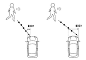
- the collision depth becomes shallower as the collision position becomes the left side (side closer to the pedestrian) (see the left figure), and the collision position becomes the right side (walking).
- the collision depth becomes deeper as it goes farther from the person (see the figure on the right).
- the reference depth to be compared with the collision depth is arbitrarily set, for example, the center of the vehicle.
- the collision probability is set to any value such as about 50% as a reference probability to be compared with the collision probability using the value obtained in the above-described processing.
- the probability depth correction amount is set to a value that increases the execution reference time TTC_th (for example, +0.5 seconds). (S282), and the correction amount calculation process based on the collision probability and the collision depth is terminated.
- the execution reference time TTC_th is a threshold value for determining the timing when the own vehicle executes control for avoiding a collision with an object.
- the execution reference time TTC_th decreases, the start timing of the control for avoiding the collision is delayed, and when the execution reference time TTC_th increases, the start timing of the control for avoiding the collision is advanced.
- the execution reference time TTC_th is reduced to a value (for example, ⁇ 0.5 seconds). Then, the correction amount calculation process based on the collision probability and the collision depth is completed.
- the probability depth is set to 0 (S285), and the correction amount calculation process based on the collision probability and the collision depth is terminated.
- the correction amount by the shadow pedestrian is calculated (S29).
- S291 the presence / absence of a pedestrian in the shade is determined.
- S291: NO the in-vehicle correction amount is set to 0 (S292), and the in-vehicle pedestrian correction amount calculation process is terminated.
- the vehicle shadow correction amount is set to a value (for example, +0.5 seconds) that increases the execution reference time TTC_th (S293). The correction amount calculation process by the pedestrian is terminated.
- the execution reference time TTC_th is calculated (S30). Specifically, the execution reference time TTC_th can be arbitrarily set. For example, when the driver performs an operation to avoid the collision at that time, the execution reference time TTC_th is set to a critical timing as to whether or not the collision can be avoided. Has been.
- the execution reference time TTC_th is corrected by each correction amount (S31).
- the execution reference time TTC_th set in the process of S30 is added with the correction amount based on the collision probability and the collision depth and the correction amount due to the vehicle shadow pedestrian to obtain a new execution reference time TTC_th.
- a collision time TTC representing the time until the host vehicle and the object collide is calculated (S32). Subsequently, it is determined whether or not the collision time TTC is shorter than the execution reference time TTC_th (S33).
- an automatic brake execution command for executing the collision mitigation operation by the brake is created (that is, a flag is set in the RAM 13) (S34).
- the automatic brake execution command is not limited to the operation of actually reducing the vehicle speed by operating the brake, but includes a preliminary operation (so-called prefill operation) for reducing the vehicle speed by the brake.
- execution control processing is executed (S36).
- execution control process an execution command is transmitted to the controlled object 40 (or to each controlled object 40 when there are a plurality of controlled objects 40) based on the created execution command (flag). Thereafter, this series of processing is temporarily terminated (END).
- the processes of S13 to S22 correspond to the process as the determination unit
- the processes of S28 to S36 correspond to the process as the execution unit
- the processes of S23 to S27 correspond to the process as the condition change unit.
- the processes of S20 to S22 correspond to the process as the condition changing unit.
- the collision possibility determination is made into the history of the position of the detected object.
- a condition change process is executed to change so as to determine the possibility of collision without being based (S26 to S27).
- the condition changing process is executed on condition that the vehicle speed is higher than the threshold value (S26). For this reason, when the speed of the vehicle is not higher than the threshold value, the condition changing process is not executed even if a pedestrian jumps out. Therefore, it is possible to suppress unnecessary collision mitigation operations from being performed.
- the condition is that the amount of the position history of the object detected by the radar sensor 32 or the camera sensor 31 is smaller than the amount of history used in the collision possibility determination (S20 to S22) based on the position history.
- a change process is executed (S23). For this reason, if the amount of the history of the position of the object detected by the detection device is equal to or larger than the amount of history used in the determination by the determination unit, the condition changing process is not executed even if a pedestrian jumps out. Normal collision possibility determination (S20 to S22) is executed. Therefore, it is possible to suppress unnecessary collision mitigation operations from being performed.
- the condition changing process is executed on condition that the speed of the detected object in the vehicle traveling direction is lower than the threshold value (S24). For this reason, when the pedestrian is moving in the traveling direction of the vehicle, the condition changing process is not executed. Therefore, it is possible to suppress unnecessary collision mitigation operations from being performed.
- condition changing process is executed on the condition that the detected object is an object that is at least partially hidden by the stationary vehicle or appears from behind the stationary vehicle. (S25). For this reason, when at least a part of the object is not hidden by the stationary vehicle, the condition changing process is not executed. Therefore, it is possible to suppress unnecessary collision mitigation operations from being performed.
- condition change processing When the condition change processing is being executed (S23 to S27), the condition change is performed when the amount of the detected position history of the object is equal to or greater than the amount of history used in the collision possibility determination based on the position history.
- the process ends (S20 to S22). For this reason, even if the condition changing process is being executed, when the normal collision possibility determination can be performed, the routine can proceed to the normal collision possibility determination. Therefore, it is possible to suppress unnecessary collision mitigation operations from being performed.
- the process of the condition changing unit when all the conditions of S23 to S27 are satisfied, the amount of position history necessary for the determination of S20 to S22 (used in the determination) is reduced and the processes of S20 to S22 are executed. Also good. According to such a configuration, the possibility of collision is determined with a smaller amount of position history than before the condition change, and the time until the determination is completed can be shortened. As a result, the vehicle collision mitigation operation can be performed at an early stage against the pedestrian jumping out.
- a part of the processing of S13 to S19 as determination not based on the position history can be omitted. Further, a part of the processing of S20 to S22 as the determination based on the position history can be omitted.
- the pedestrians appearing in the shade of the vehicle are not limited to pedestrians appearing behind the stationary vehicles, but may include pedestrians appearing behind the stationary objects such as buildings and street trees.
- ⁇ Bicycles can be used for judgment instead of pedestrians.
- a monocular camera may be employed as the camera sensor 31. In that case, the distance to the object is calculated based on the processing of the captured image by the monocular camera.
- a configuration including only one of the radar sensor 32 and the camera sensor 31 may be employed. In that case, the determination based on the FSN position may be omitted.
Landscapes
- Engineering & Computer Science (AREA)
- Automation & Control Theory (AREA)
- Transportation (AREA)
- Mechanical Engineering (AREA)
- Human Computer Interaction (AREA)
- Physics & Mathematics (AREA)
- General Physics & Mathematics (AREA)
- Traffic Control Systems (AREA)
- Control Of Driving Devices And Active Controlling Of Vehicle (AREA)
Abstract
車両前方の対象物の位置を検出する検出装置(31、32)と、車両と対象物との衝突緩和動作を実行する衝突緩和装置(40)とを備える車両に適用され、衝突緩和装置による衝突緩和動作を制御する制御装置(10)であって、検出装置により検出された対象物の位置と対象物の位置の履歴とに基づいて、車両と対象物との衝突可能性を判定する判定部と、衝突可能性が所定値よりも高いと判定された場合に、衝突緩和装置により衝突緩和動作を実行させる実行部と、検出された対象物が、静止物の陰から飛び出してきた歩行者又は自転車であると判定した場合に、判定部による判定を、対象物の位置の履歴に基づかず、衝突可能性を判定するように変更する条件変更処理を実行する条件変更部と、を備える。
Description
本出願は、2016年3月4日に出願された日本出願番号2016-041833号に基づくもので、ここにその記載内容を援用する。
本開示は、車両と対象物との衝突緩和動作を制御する制御装置に関する。
従来、この種の衝突緩和制御装置において、車両に対する対象物の過去の位置を接続した軌跡を伸ばして、この軌跡が車両と重なる点を衝突位置として衝突可能性を判定するものがある(特許文献1参照)。
しかしながら、特許文献1に記載のものでは、対象物の軌跡を求めるために対象物の複数の過去位置(位置の履歴)を必要とすることから、衝突可能性の判定終了までに時間を要するおそれがある。特に、静止物の陰から歩行者又は自転車が飛び出してきた場合は、車両と衝突するまでの時間が短くなるため、車両の衝突緩和動作を早期に実行する必要がある。
本開示は、こうした実情に鑑みてなされたものであり、その主たる目的は、不要な衝突緩和動作の実行を抑制しつつ、飛び出しに対して衝突緩和動作を早期に実行することのできる衝突緩和制御装置を提供することにある。
本開示は、上記課題を解決するために、以下の手段を採用した。
第1の手段は、車両前方の対象物の位置を検出する検出装置と、前記車両と前記対象物との衝突緩和動作を実行する衝突緩和装置とを備える車両に適用され、前記衝突緩和装置による前記衝突緩和動作を制御する制御装置であって、前記検出装置により検出された前記対象物の位置と前記対象物の位置の履歴とに基づいて、前記車両と前記対象物との衝突可能性を判定する判定部と、前記判定部により前記衝突可能性が所定値よりも高いと判定された場合に、前記衝突緩和装置により衝突緩和動作を実行させる実行部と、前記検出装置により検出された前記対象物が、静止物の陰から飛び出してきた歩行者又は自転車であると判定した場合に、前記判定部による前記判定を、前記検出装置により検出された前記対象物の位置の履歴に基づかず、前記衝突可能性を判定するように変更する条件変更処理を実行する条件変更部と、を備える。
上記構成によれば、検出装置により車両前方の対象物の位置が検出される。判定部によって、検出装置により検出された対象物の位置と対象物の位置の履歴とに基づいて、車両と対象物との衝突可能性が判定される。そして、判定部により衝突可能性が所定値よりも高いと判定された場合に、衝突緩和装置により車両と対象物との衝突緩和動作が実行される。
ここで、条件変更部は、検出装置により検出された対象物が、静止物の陰から飛び出してきた歩行者又は自転車であると判定した場合に、判定部による判定を、検出装置により検出された対象物の位置の履歴に基づかず、衝突可能性を判定するように変更する条件変更処理を実行する。これにより、そもそも対象物の位置の履歴を用いる必要がなくなるため、車両と対象物との衝突可能性を迅速に判定することができる。その結果、歩行者又は自転車の飛び出しに対して、車両の衝突緩和動作を早期に実行することができる。さらに、通常は対象物の位置と対象物の位置の履歴とに基づいて、車両と対象物との衝突可能性が判定されるため、不要な衝突緩和動作の実行を抑制することができる。
なお、衝突緩和装置は、車両を制動する制動装置や、車両を操舵する操舵装置、警報を発する警報装置等を含む。制動装置による衝突緩和動作は、車両の速度を実際に低下させる動作に限らず、車両の速度を減少させるための予備動作(いわゆるプレフィル動作等)を含む。
第2の手段は、車両前方の対象物の位置を検出する検出装置と、前記車両と前記対象物との衝突緩和動作を実行する衝突緩和装置とを備える車両に適用され、前記衝突緩和装置による前記衝突緩和動作を制御する制御装置であって、前記検出装置により検出された前記対象物の位置と前記対象物の位置の履歴とに基づいて、前記車両と前記対象物との衝突可能性を判定する判定部と、前記判定部により前記衝突可能性が所定値よりも高いと判定された場合に、前記衝突緩和装置により衝突緩和動作を実行させる実行部と、前記検出装置により検出された前記対象物が、静止物の陰から飛び出してきた歩行者又は自転車であると判定した場合に、前記判定部による前記判定において用いる前記履歴の量を減少させる条件変更処理を実行する条件変更部と、を備える。
上記構成によれば、条件変更部は、検出装置により検出された対象物が、静止物の陰から飛び出してきた歩行者又は自転車であると判定した場合に、判定部による判定において用いる履歴の量を減少させる条件変更処理を実行する。このため、条件変更前よりも少ない位置履歴で衝突可能性が判定され、判定が終了するまでの時間を短縮することができる。その結果、歩行者又は自転車の飛び出しに対して、車両の衝突緩和動作を早期に実行することができる。
本開示についての上記目的およびその他の目的、特徴や利点は、添付の図面を参照しながら下記の詳細な記述により、より明確になる。その図面は、
図1は、プリクラッシュセーフティシステムの概要を示すブロック図であり、
図2は、衝突緩和制御の手順を示すフローチャートであり、
図3は、衝突横位置を示す鳥瞰図であり、
図4は、衝突確率の算出方法を示す模式図であり、
図5は、車陰歩行者を示す鳥瞰図であり、
図6は、衝突確率及び衝突深さによる補正量算出処理の手順を示すフローチャートであり、
図7は、衝突深さを示す鳥瞰図であり、
図8は、車陰歩行者による補正量算出処理の手順を示すフローチャートである。
以下、車両に搭載されたプリクラッシュセーフティシステム(以下、「PCS」という)に具現化した一実施形態について、図面を参照しつつ説明する。PCSは、車両が対象物に衝突するおそれがあることを検出し、車両の衝突を抑制したり、車両が衝突する際にその被害を緩和させたりするシステムである。
図1に示すように、PCS100は、衝突緩和制御装置10と、各種センサ30と、被制御対象40とを備えている。
各種センサ30としては、例えば、カメラセンサ31、レーダセンサ32、ヨーレートセンサ33、車輪速センサ34等を備えている。カメラセンサ31(検出装置に相当)は、例えば対象物までの距離を検出可能なステレオカメラとして構成されており、撮影画像に基づいて画像中の歩行者、路上障害物や他車両等の対象物の形状と対象物までの距離とを認識する。
レーダセンサ32(検出装置に相当)は、対象物及びその位置(自車両に対する相対位置)を検出する。ヨーレートセンサ33は、車両の旋回角速度を検出する周知のヨーレートセンサである。
車輪速センサ34は、車輪の回転速度、すなわち車両の速度を検出する。これらの各種センサ30による検出結果は、衝突緩和制御装置10によって取得される。
なお、カメラセンサ31やレーダセンサ32は、予め設定された所定の周期(例えば100ms)毎に、車両の進行方向に位置する対象物を検出する。また、レーダセンサ32は、指向性のある電磁波を対象物に対して発射し、その反射波を受信することによって、対象物の形状や大きさも検出する。
衝突緩和制御装置10は、CPU11,ROM12,RAM13等を備えた周知のマイクロコンピュータである。そして、衝突緩和制御装置10は、各種センサ30による検出結果等に基づいて、ROM12に格納されたプログラムを実行することによって、後述する衝突緩和制御等の各種制御を実行する。
衝突緩和制御装置10は、このような制御を実行し、その結果に応じて被制御対象40を動作させる。なお、被制御対象40(衝突緩和装置に相当)としては、例えば、ブレーキ(制動装置に相当)や、ステアリング(操舵装置に相当)、シートベルト等を駆動するアクチュエータ(衝撃抑制装置に相当)や、警報を発する警報装置等が挙げられる。以下、本実施形態においては、被制御対象40がブレーキであり、衝突を緩和する対象物が歩行者である場合を例にして説明する。
このように、CPU11が自動ブレーキとしての機能を実行させる際には、車輪速センサ34からの検出信号に応じて、予め設定された減速度および減速量(自動ブレーキ作動前後の速度差)となるように、被制御対象40を動作させる。
次に、自動ブレーキを実行する際の処理である衝突緩和制御について、図2のフローチャートを参照して説明する。この一連の処理は、衝突緩和制御装置10により、所定周期(例えば約50ms)で繰り返し実行される。
まず、対象物の情報を入力する(S11)。具体的には、カメラセンサ31やレーダセンサ32によって検出された最新の対象物の位置の情報を取得する。そして、レーダセンサ32により検出された対象物の位置であるレーダ検出位置と、カメラセンサ31により検出された対象物の位置であるカメラ検出位置とに基づいて、それらの位置を総合的に評価したFSN位置を算出する。
続いて、対象物の認識を行う(S12)。具体的には、カメラセンサ31にて得られた対象物の形状等(パターンマッチング等)に応じて、対象物の種別(車両、歩行者、自転車、バイク等)を認識する。そして、前回以前にRAM13等に記録された対象物と今回認識した対象物とを対応付ける。また、各対象物の挙動や位置関係(自車両を基準とした対象物の座標)、各対象物との相対速度も認識する。
続いて、ブレーキを動作させるための条件が成立しているか否か判定する(S13~S19)。これらS13~S19の判定は、レーダセンサ32やカメラセンサ31により検出された位置の履歴に基づかない判定である。
具体的には、対象物の横位置の条件が成立しているか否か判定する(S13)。詳しくは、自車両に対する対象物の横位置が、自車両の幅の範囲に重なっているか否か判定する。この横位置条件の判定は、上記レーダ検出位置とFSN位置とを用いてそれぞれ実行する。
両位置を用いた判定において、対象物の横位置の条件が成立していると判定した場合(S13:YES)、FSN存在確率の条件が成立しているか否か判定する(S14)。詳しくは、レーダセンサ32により対象物が検出されている場合にFSN存在確率が増加され、レーダセンサ32により対象物が検出されていない場合にFSN存在確率が減少される。そして、FSN存在確率が閾値よりも高いか否か判定する。
FSN存在確率の条件が成立していると判定した場合(S14:YES)、折り返し物確率の条件が成立しているか否か判定する(S15)。詳しくは、レーダセンサ32により検出された対象物が、衝突するおそれのない対象物からの反射波に基づき検出されている場合に、折り返し物確率が増加される。そして、折り返し物確率が閾値よりも低いか否か判定する。
折り返し物確率の条件が成立していると判定した場合(S15:YES)、物標種別の条件が成立しているか否か判定する(S16)。詳しくは、カメラセンサ31により認識された物標の種別が、車両、歩行者、自転車、バイク等、衝突判定を行う対象であるか否か判定する。
物標種別の条件が成立していると判定した場合(S16:YES)、FSN状態の条件が成立しているか否か判定する(S17)。詳しくは、レーダセンサ32により検出された対象物と、カメラセンサ31により検出された対象物とが、同一の対象物であると判定しているFSN状態が成立しているか否か判定する。
FSN状態の条件が成立していると判定した場合(S17:YES)、垂直軸ずれの条件が成立しているか否か判定する(S18)。詳しくは、レーダセンサ32の垂直軸方向(上下方向)がずれていないか否か判定する。
垂直軸ずれの条件が成立していると判定した場合(S18:YES)、水平軸ずれの条件が成立しているか否か判定する(S19)。詳しくは、レーダセンサ32の水平軸方向(左右方向)がずれていないか否か判定する。
水平軸ずれの条件が成立していると判定した場合(S19:YES)、レーダセンサ32やカメラセンサ31により検出された位置の履歴に基づいて、ブレーキを動作させるための条件が成立しているか否か判定する(S20~S22)。なお、判定に必要な量の位置の履歴が蓄積されていない場合は、条件が設立していないと判定する。
具体的には、位置履歴に基づく衝突横位置の条件が成立しているか否か判定する(S20)。詳しくは、対象物の衝突横位置を算出する。衝突横位置とは、図3に示すように、自車両の幅方向の中心から対象物が衝突すると予想される位置(衝突位置)までの距離(例えば中心よりも左側が正の値、中心よりも右側が負の値)を示す。対象物の相対的な位置を接続した軌跡(最小二乗法等で近似された軌跡)を伸ばし、この軌跡が車両と重なる点(自車両の前面)を衝突位置として推定する。そして、衝突横位置が自車両の幅の範囲内の位置であるか否か判定する。この衝突横位置条件の判定は、上記レーダ検出位置とFSN位置とを用いてそれぞれ実行する。
両位置を用いた判定において、位置履歴に基づく衝突横位置の条件が成立していると判定した場合(S20:YES)、位置履歴に基づく衝突横位置の確率の条件が成立しているか否か判定する(S21)。詳しくは、自車両と対象物とが衝突する確率を表す衝突確率を算出する。衝突確率は、前述の衝突横位置に応じて予め設定されたポイント(点数)を処理の度に積算する積算方式を採用する。具体的には、図4に示すように、予め衝突位置を複数の領域に区分し、区分毎にポイントを対応付ける。詳しくは、衝突位置が車幅方向の中心に近づくにつれて(衝突横位置の絶対値が小さくなるにつれて)より高いポイントを対応付ける。
図4に示す例では、衝突位置を5つの領域に区分し、車幅方向の中心付近の領域には20ポイント、この領域の左右に隣接する領域にはそれぞれ10ポイント、車両の幅よりも外側の左右の領域にはそれぞれ-10ポイントを対応付けている。例えば、1回目の処理において衝突位置が20ポイントに対応する領域であれば20ポイントが加算され、このポイントに所定の係数(例えば1)を乗じることで、衝突確率が20%となる。次に、2回目の処理において衝突位置が10ポイントに対応する領域であれば、10ポイントが加算され衝突確率が30%となる。3回目の処理において衝突位置がマイナス10ポイントに対応する領域であれば、10ポイントが減算され衝突確率が20%となる。そして、衝突確率が閾値よりも高いか否か判定する。この衝突横位置の確率の条件判定は、上記レーダ検出位置とFSN位置とを用いてそれぞれ実行する。
両位置を用いた判定において、位置履歴に基づく衝突横位置の確率の条件が成立していると判定した場合(S21:YES)、横断条件が成立しているか否か判定する(S22)。詳しくは、FSN位置に基づいて算出される対象物の横速度が閾値よりも高いか否か判定する。この閾値は、対象物が自車両の進行方に対して垂直な方向(横方向)へ移動していることを判定することのできる値である。
横断条件が成立していると判定した場合(S22:YES)、S28~34の処理を実行する。すなわち、S13~S22の条件が全て成立した場合(衝突可能性が所定値よりも高い場合)、自車両と対象物とが衝突するまでの時間を表す衝突時間TTCに基づいて、ブレーキにより衝突緩和動作を実行させる自動ブレーキ実行指令を作成する。
一方、S13~S19の処理のいずれかで条件が設立していないと判定した場合、自動ブレーキ実行指令は作成しない(S35)。
また、S20~S22の処理(位置の履歴に基づく条件判定)のいずれかで条件が成立していないと判定した場合、検出された対象物が静止物の陰から飛び出してきた歩行者であるか否か判定する(S23~25)。
具体的には、位置の履歴量の条件が成立しているか否か判定する(S23)。詳しくは、検出された対象物の位置の履歴の量が、位置の履歴に基づく条件判定(S20~S22)に必要な量(用いられる量)よりも少ない、すなわち対象物を検出した直後であるか否か判定する。
位置の履歴量の条件が成立していると判定した場合(S23:YES)、歩行者の速度の条件を満たしているか否か判定する(S24)。詳しくは、検出された対象物(歩行者)の車両進行方向の速度が閾値(所定速度)よりも低い、すなわち車両進行方向に移動している対象物ではないか否か判定する。
歩行者の速度の条件を満たしていると判定した場合(S24:YES)、車陰歩行者の条件が成立しているか否か判定する(S25)。詳しくは、対象物(歩行者)が車陰歩行者であるか否か判定する。車陰歩行者とは、例えば、図5に示すように、自車両の進行方向に静止車両(静止物に相当)が存在する状況において、身体の少なくとも一部が静止車両で隠れている歩行者、または静止車両の陰から現れた歩行者である。すなわち、車陰歩行者は、静止車両の向こう側にいる歩行者、または静止車両の向こう側から現れる歩行者である。
車陰歩行者の条件が成立していると判定した場合(S25:YES)、自車速の条件が成立しているか否か判定する(S26)。詳しくは、自車両の速度が閾値(所定速度)よりも高いか否か判定する。この閾値は、静止車両の陰からの歩行者の飛び出しに対して、運転者が衝突を回避することが困難となる値である。
自車速の条件が成立していると判定した場合(S26:YES)、自車の直進条件が成立しているか否か判定する(S27)。詳しくは、ヨーレートセンサ33の検出値に基づいて、自車両が直進している、すなわち旋回をしていないか否か判定する。
自車の直進条件が成立していると判定した場合(S27:YES)、S28~34の処理を実行する。すなわち、S13~S19、及びS23~S27の条件が全て成立した場合(衝突可能性が所定値よりも高い場合)も、衝突時間TTCに基づいて自動ブレーキ実行指令を作成する。
一方、S23~S27の処理のいずれかで条件が設立していないと判定した場合、自動ブレーキ実行指令は作成しない(S35)。
S28では、衝突確率及び衝突深さによる補正量を算出する(S28)。この処理では、図6に示すように、まず、衝突深さと基準値である基準深さとを比較するとともに、衝突確率と基準値である基準確率とを比較する(S281、S283)。
ここで、衝突深さとは、例えば図7に示すように、自車両の幅方向の中心から見て、幅方向のうち歩行者が存在する側の自車両の端部から衝突位置までの距離を表す。具体的には、歩行者が自車両の左側から横断する場合、衝突位置が左側(歩行者に近い側)になるにつれて衝突深さが浅くなり(左側の図参照)、衝突位置が右側(歩行者から遠い側)になるにつれて衝突深さが深くなる(右側の図参照)。
また、衝突深さとの比較対象となる基準深さは、例えば車両の中心等、任意に設定される。また、衝突確率は前述の処理で求めた値を利用し、衝突確率との比較対象となる基準確率は例えば50%程度等、任意に設定される。
衝突深さが基準深さ以上であり、かつ衝突確率が基準確率以上であれば(S281:YES)、確率深さ補正量を、実行基準時間TTC_thが大きくなるような値(例えば+0.5秒)に設定し(S282)、衝突確率及び衝突深さによる補正量算出処理を終了する。
ここで、実行基準時間TTC_thは、自車両が対象物との衝突を回避する制御を実行する際のタイミングを決定するための閾値である。実行基準時間TTC_thが小さくなると、衝突を回避する制御の開始タイミングが遅くなり、実行基準時間TTC_thが大きくなると、衝突を回避する制御の開始タイミングが早くなる。
衝突深さが基準深さ未満であり、かつ衝突確率が基準確率未満であれば(S281:NO、S283:YES)、実行基準時間TTC_thが小さくなるような値(例えば-0.5秒)に設定し(S284)、衝突確率及び衝突深さによる補正量算出処理を終了する。
衝突深さが基準深さ以上であり衝突確率が基準確率未満、又は衝突深さが基準深さ未満であり衝突確率が基準確率以上であれば(S281:NO、S283:NO)、確率深さ補正量を0に設定し(S285)、衝突確率及び衝突深さによる補正量演算処理を終了する。
図2に戻り、続いて、車陰歩行者による補正量を算出する(S29)。この処理では、図8に示すように、まず、車陰歩行者の有無を判定する(S291)。車陰歩行者が存在しないと判定した場合(S291:NO)、車陰補正量を0に設定し(S292)、車陰歩行者による補正量算出処理を終了する。また、車陰歩行者が存在すると判定した場合(S291:YES)、車陰補正量を、実行基準時間TTC_thが大きくなるような値(例えば+0.5秒)に設定し(S293)、車陰歩行者による補正量算出処理を終了する。
図2に戻り、続いて、実行基準時間TTC_thを算出する(S30)。具体的には、実行基準時間TTC_thは、任意に設定されうるが、例えば、運転者がその時点で衝突を回避する操作をしたときに、衝突を回避できるか否かの臨界となるタイミングに設定されている。
続いて、実行基準時間TTC_thを各補正量により補正する(S31)。この処理では、S30の処理で設定された実行基準時間TTC_thに対して、衝突確率及び衝突深さによる補正量と車陰歩行者による補正量とを加算し、新たな実行基準時間TTC_thを得る。
そして、自車両と対象物との相対速度に基づいて、自車両と対象物とが衝突するまでの時間を表す衝突時間TTCを演算する(S32)。続いて、衝突時間TTCが実行基準時間TTC_thよりも短いか否か判定する(S33)。
衝突時間TTCが実行基準時間TTC_thよりも短いと判定した場合(S33:YES)、ブレーキにより衝突緩和動作を実行させる自動ブレーキ実行指令を作成(すなわちRAM13においてフラグをセット)する(S34)。自動ブレーキ実行指令は、ブレーキを動作させて車両の速度を実際に低下させる動作に限らず、ブレーキにより車両の速度を低下させるための予備動作(いわゆるプレフィル動作)を含む。
一方、衝突時間TTCが実行基準時間TTC_thよりも短くないと判定した場合(S33:NO)、自動ブレーキ実行指令を作成しない(すなわちRAM13においてフラグをリセットする)(S35)。
そして、実行制御処理を実行する(S36)。実行制御処理では、作成された実行指令(フラグ)に基づいて、被制御対象40に対して(被制御対象40が複数の場合はそれぞれの被制御対象40に対して)実行指令を送信する。その後、この一連の処理を一旦終了する(END)
なお、S13~S22の処理が判定部としての処理に相当し、S28~S36の処理が実行部としての処理に相当し、S23~S27の処理が条件変更部としての処理に相当する。S23~S27の条件が全て成立した場合は、S20~S22の処理は条件変更部としての処理に相当する。
なお、S13~S22の処理が判定部としての処理に相当し、S28~S36の処理が実行部としての処理に相当し、S23~S27の処理が条件変更部としての処理に相当する。S23~S27の条件が全て成立した場合は、S20~S22の処理は条件変更部としての処理に相当する。
以上詳述した本実施形態は、以下の利点を有する。
・検出された対象物が、静止車両の陰から飛び出してきた歩行者であると判定した場合に(図2のS23~S25)、衝突可能性判定を、検出された対象物の位置の履歴に基づかず、衝突可能性を判定するように変更する条件変更処理を実行する(S26~S27)。これにより、そもそも対象物の位置の履歴を用いる必要がなくなるため、車両と対象物との衝突可能性を迅速に判定することができる。その結果、歩行者の飛び出しに対して、車両の衝突緩和動作を早期に実行することができる。さらに、通常は対象物の位置と対象物の位置の履歴とに基づいて、車両と対象物との衝突可能性が判定されるため(S13~S22)、不要な衝突緩和動作の実行を抑制することができる。
・歩行者の飛び出しがあったとしても、車両の速度が低い場合は衝突までに時間的な余裕がある。このような場合に、車両の衝突緩和動作を早期に実行すると、不要な衝突緩和動作の実行になるおそれがある。この点、車両の速度が閾値よりも高いことを条件として、条件変更処理が実行される(S26)。このため、車両の速度が閾値よりも高くない場合は、歩行者の飛び出しがあったとしても、条件変更処理が実行されない。したがって、不要な衝突緩和動作が実行されることを抑制することができる。
・歩行者の飛び出しがあったとしても、車両が旋回している場合は運転者がそれを回避する操作を行っている可能性がある。このような場合に、車両の衝突緩和動作を早期に実行すると、不要な衝突緩和動作の実行になるおそれがある。この点、車両が直進していることを条件として、条件変更処理が実行される(S27)。このため、車両が直進していない場合は、歩行者の飛び出しがあったとしても、条件変更処理が実行されない。したがって、不要な衝突緩和動作が実行されることを抑制することができる。
・レーダセンサ32やカメラセンサ31により検出された対象物の位置の履歴の量が、位置の履歴に基づく衝突可能性判定(S20~S22)において用いる履歴の量よりも少ないことを条件として、条件変更処理が実行される(S23)。このため、検出装置により検出された対象物の位置の履歴の量が、判定部による判定において用いる履歴の量以上の場合は、歩行者の飛び出しがあったとしても、条件変更処理が実行されず、通常の衝突可能性判定(S20~S22)が実行される。したがって、不要な衝突緩和動作が実行されることを抑制することができる。
・歩行者が静止車両の近傍に存在したとしても、車両の進行方向に移動している場合は飛び出しではない可能性がある。このような場合に、車両の衝突緩和動作を早期に実行すると、不要な衝突緩和動作の実行になるおそれがある。この点、検出された対象物の車両進行方向の速度が閾値よりも低いことを条件として、条件変更処理が実行される(S24)。このため、歩行者が車両の進行方向に移動している場合は、条件変更処理が実行されない。したがって、不要な衝突緩和動作が実行されることを抑制することができる。
・静止車両の陰から歩行者が飛び出してくる状況は、歩行者の少なくとも一部が静止車両で隠れている場合に生じ易い。この点、検出された対象物が、その少なくとも一部が静止車両で隠れている対象物である、又は静止車両の陰から現れた対象物であることを条件として、条件変更処理が実行される(S25)。このため、対象物の少なくとも一部が静止車両で隠れている状態でない場合は、条件変更処理が実行されない。したがって、不要な衝突緩和動作が実行されることを抑制することができる。
・条件変更処理の実行中(S23~S27)に、検出された対象物の位置の履歴の量が、位置の履歴に基づく衝突可能性判定において用いる履歴の量以上になった場合に、条件変更処理を終了する(S20~S22)。このため、条件変更処理が実行されていても、通常の衝突可能性判定を行うことができようになった場合は、通常の衝突可能性判定に移行することができる。したがって、不要な衝突緩和動作が実行されることを抑制することができる。
なお、上記実施形態を、以下のように変更して実施することもできる。上記実施形態と同一の部材については、同一の符号を付すことにより説明を省略する。
・条件変更部の処理として、S23~S27の条件が全て成立した場合に、S20~S22の判定に必要な(判定で用いる)位置履歴の量を減少させてS20~S22の処理を実行させてもよい。こうした構成によれば、条件変更前よりも少ない量の位置履歴で衝突可能性が判定され、判定が終了するまでの時間を短縮することができる。その結果、歩行者の飛び出しに対して、車両の衝突緩和動作を早期に実行することができる。
・飛び出し判定としてのS23~S25の処理の一部を省略することもできる。また、S26,S27の処理を省略することもできる。
・位置履歴に基づかない判定としてのS13~S19の処理の一部を省略することもできる。また、位置履歴に基づく判定としてのS20~S22の処理の一部を省略することもできる。
・SS28,S29,S31の処理を省略することもできる。
・車陰歩行者は、静止車両の陰から現れる歩行者に限らず、建物や街路樹等の静止物の陰から現れる歩行者を含めてもよい。
・歩行者に代えて自転車を判定の対象とすることもできる。
・カメラセンサ31として、単眼カメラを採用することもできる。その場合は、単眼カメラによる撮影画像の処理に基づいて、対象物までの距離を算出する。レーダセンサ32及びカメラセンサ31の一方のみを備える構成を採用することもできる。その場合、FSN位置に基づく判定を省略すればよい。
本開示は、実施例に準拠して記述されたが、本開示は当該実施例や構造に限定されるものではないと理解される。本開示は、様々な変形例や均等範囲内の変形をも包含する。加えて、様々な組み合わせや形態、さらには、それらに一要素のみ、それ以上、あるいはそれ以下、を含む他の組み合わせや形態をも、本開示の範疇や思想範囲に入るものである。
Claims (8)
- 車両前方の対象物の位置を検出する検出装置(31、32)と、前記車両と前記対象物との衝突緩和動作を実行する衝突緩和装置(40)とを備える車両に適用され、前記衝突緩和装置による前記衝突緩和動作を制御する制御装置(10)であって、
前記検出装置により検出された前記対象物の位置と前記対象物の位置の履歴とに基づいて、前記車両と前記対象物との衝突可能性を判定する判定部と、
前記判定部により前記衝突可能性が所定値よりも高いと判定された場合に、前記衝突緩和装置により衝突緩和動作を実行させる実行部と、
前記検出装置により検出された前記対象物が、静止物の陰から飛び出してきた歩行者又は自転車であると判定した場合に、前記判定部による前記判定を、前記検出装置により検出された前記対象物の位置の履歴に基づかず、前記衝突可能性を判定するように変更する条件変更処理を実行する条件変更部と、
を備える衝突緩和制御装置。 - 車両前方の対象物の位置を検出する検出装置(31、32)と、前記車両と前記対象物との衝突緩和動作を実行する衝突緩和装置(40)とを備える車両に適用され、前記衝突緩和装置による前記衝突緩和動作を制御する制御装置(10)であって、
前記検出装置により検出された前記対象物の位置と前記対象物の位置の履歴とに基づいて、前記車両と前記対象物との衝突可能性を判定する判定部と、
前記判定部により前記衝突可能性が所定値よりも高いと判定された場合に、前記衝突緩和装置により衝突緩和動作を実行させる実行部と、
前記検出装置により検出された前記対象物が、静止物の陰から飛び出してきた歩行者又は自転車であると判定した場合に、前記判定部による前記判定において用いる前記履歴の量を減少させる条件変更処理を実行する条件変更部と、
を備える衝突緩和制御装置。 - 前記条件変更部は、前記車両の速度が所定速度よりも高いことを条件として、前記条件変更処理を実行する請求項1又は2に記載の衝突緩和制御装置。
- 前記条件変更部は、前記車両が直進していることを条件として、前記条件変更処理を実行する請求項1~3のいずれか1項に記載の衝突緩和制御装置。
- 前記条件変更部は、前記検出装置により検出された前記対象物の位置の履歴の量が、前記判定部による前記判定において用いる前記履歴の量よりも少ないことを条件として、前記条件変更処理を実行する請求項1~4のいずれか1項に記載の衝突緩和制御装置。
- 前記条件変更部は、前記検出装置により検出された前記対象物の車両進行方向の速度が所定速度よりも低いことを条件として、前記条件変更処理を実行する請求項1~5のいずれか1項に記載の衝突緩和制御装置。
- 前記条件変更部は、前記検出装置により検出された前記対象物が、その少なくとも一部が静止物で隠れている対象物である、又は静止物の陰から現れた対象物であることを条件として、前記条件変更処理を実行する請求項1~6のいずれか1項に記載の衝突緩和制御装置。
- 前記条件変更部は、前記条件変更処理の実行中に、前記検出装置により検出された前記対象物の位置の履歴の量が、前記判定部による前記判定において用いる前記対象物の位置の履歴の量以上になった場合に、前記条件変更処理を終了する請求項1~7のいずれか1項に記載の衝突緩和制御装置。
Priority Applications (1)
| Application Number | Priority Date | Filing Date | Title |
|---|---|---|---|
| US16/080,459 US20190061750A1 (en) | 2016-03-04 | 2017-02-13 | Collision mitigation control device |
Applications Claiming Priority (2)
| Application Number | Priority Date | Filing Date | Title |
|---|---|---|---|
| JP2016041833A JP6597408B2 (ja) | 2016-03-04 | 2016-03-04 | 衝突緩和制御装置 |
| JP2016-041833 | 2016-03-04 |
Publications (1)
| Publication Number | Publication Date |
|---|---|
| WO2017150159A1 true WO2017150159A1 (ja) | 2017-09-08 |
Family
ID=59742831
Family Applications (1)
| Application Number | Title | Priority Date | Filing Date |
|---|---|---|---|
| PCT/JP2017/005150 Ceased WO2017150159A1 (ja) | 2016-03-04 | 2017-02-13 | 衝突緩和制御装置 |
Country Status (3)
| Country | Link |
|---|---|
| US (1) | US20190061750A1 (ja) |
| JP (1) | JP6597408B2 (ja) |
| WO (1) | WO2017150159A1 (ja) |
Families Citing this family (15)
| Publication number | Priority date | Publication date | Assignee | Title |
|---|---|---|---|---|
| JP6868699B2 (ja) * | 2017-08-07 | 2021-05-12 | 日立Astemo株式会社 | 路側物検出装置、路側物検出方法及び路側物検出システム |
| US10435035B2 (en) * | 2017-10-17 | 2019-10-08 | Denso International America, Inc. | Screen reduction system for autonomous vehicles |
| JP7245006B2 (ja) * | 2018-07-05 | 2023-03-23 | 株式会社デンソー | 車両の運転支援制御装置、車両の運転支援システムおよび車両の運転支援制御方法 |
| KR102650306B1 (ko) * | 2018-10-16 | 2024-03-22 | 주식회사 에이치엘클레무브 | 차량 제어 시스템, 차량 제어 방법 |
| CN114127821A (zh) * | 2019-07-12 | 2022-03-01 | 日产自动车株式会社 | 信息处理装置、信息处理方法以及程序 |
| KR102749737B1 (ko) * | 2019-09-09 | 2025-01-08 | 주식회사 에이치엘클레무브 | 차량 제어 장치 및 그 제어 방법 |
| CN110949381B (zh) * | 2019-11-12 | 2021-02-12 | 深圳大学 | 一种驾驶行为危险度的监测方法及装置 |
| CN111504328B (zh) * | 2020-05-22 | 2022-07-08 | 梅卡曼德(北京)机器人科技有限公司 | 机器人运动规划方法、路径规划方法、抓取方法及其装置 |
| US11738682B2 (en) * | 2020-10-08 | 2023-08-29 | Motional Ad Llc | Communicating vehicle information to pedestrians |
| KR20220102175A (ko) * | 2021-01-11 | 2022-07-20 | 삼성전자주식회사 | 안전한 보행을 위한 피드백 제공 방법 및 장치 |
| WO2023276919A1 (ja) * | 2021-06-30 | 2023-01-05 | 株式会社アイシン | 自動制動制御装置及び自動制動処理プログラム |
| EP4112411B1 (en) * | 2021-07-01 | 2024-03-27 | Zenseact AB | Estimation of accident intensity for vehicles |
| JP2024048297A (ja) * | 2022-09-27 | 2024-04-08 | 日本電気株式会社 | 運転支援装置、運転支援方法、及びプログラム |
| KR20240123114A (ko) * | 2023-02-06 | 2024-08-13 | 현대자동차주식회사 | 충돌 방지 보조 장치 및 방법 |
| JP2025095725A (ja) | 2023-12-15 | 2025-06-26 | トヨタ自動車株式会社 | 車両制御装置、車両制御方法、及び車両制御プログラム |
Citations (3)
| Publication number | Priority date | Publication date | Assignee | Title |
|---|---|---|---|---|
| JPH06119599A (ja) * | 1992-10-08 | 1994-04-28 | Nissan Motor Co Ltd | 車両走行制御装置 |
| JP2008247111A (ja) * | 2007-03-29 | 2008-10-16 | Fuji Heavy Ind Ltd | 車両の衝突安全制御システム |
| JP2014213777A (ja) * | 2013-04-26 | 2014-11-17 | 株式会社デンソー | 衝突緩和装置 |
Family Cites Families (6)
| Publication number | Priority date | Publication date | Assignee | Title |
|---|---|---|---|---|
| US7881868B2 (en) * | 2007-06-12 | 2011-02-01 | Palo Alto Research Center Incorporated | Dual assessment for early collision warning |
| JP2009196464A (ja) * | 2008-02-20 | 2009-09-03 | Keihin Corp | 歩行者衝突検知装置及び歩行者保護システム |
| JP4605265B2 (ja) * | 2008-07-22 | 2011-01-05 | トヨタ自動車株式会社 | 車両の操舵装置 |
| EP2615596B1 (en) * | 2010-09-08 | 2024-10-30 | Toyota Jidosha Kabushiki Kaisha | Moving-object prediction device, virtual-mobile-object prediction device, program, mobile-object prediction method, and virtual-mobile-object prediction method |
| WO2012172632A1 (ja) * | 2011-06-13 | 2012-12-20 | トヨタ自動車株式会社 | 運転支援装置及び運転支援方法 |
| KR101957117B1 (ko) * | 2015-09-30 | 2019-03-11 | 닛산 지도우샤 가부시키가이샤 | 정보 제시 장치 및 정보 제시 방법 |
-
2016
- 2016-03-04 JP JP2016041833A patent/JP6597408B2/ja active Active
-
2017
- 2017-02-13 US US16/080,459 patent/US20190061750A1/en not_active Abandoned
- 2017-02-13 WO PCT/JP2017/005150 patent/WO2017150159A1/ja not_active Ceased
Patent Citations (3)
| Publication number | Priority date | Publication date | Assignee | Title |
|---|---|---|---|---|
| JPH06119599A (ja) * | 1992-10-08 | 1994-04-28 | Nissan Motor Co Ltd | 車両走行制御装置 |
| JP2008247111A (ja) * | 2007-03-29 | 2008-10-16 | Fuji Heavy Ind Ltd | 車両の衝突安全制御システム |
| JP2014213777A (ja) * | 2013-04-26 | 2014-11-17 | 株式会社デンソー | 衝突緩和装置 |
Also Published As
| Publication number | Publication date |
|---|---|
| US20190061750A1 (en) | 2019-02-28 |
| JP2017154683A (ja) | 2017-09-07 |
| JP6597408B2 (ja) | 2019-10-30 |
Similar Documents
| Publication | Publication Date | Title |
|---|---|---|
| JP6597408B2 (ja) | 衝突緩和制御装置 | |
| JP6561584B2 (ja) | 車両制御装置、及び車両制御方法 | |
| JP5783430B2 (ja) | 衝突緩和装置 | |
| JP7077606B2 (ja) | 衝突判定装置 | |
| CN108602494B (zh) | 车辆控制装置以及车辆控制方法 | |
| US9460627B2 (en) | Collision determination device and collision mitigation device | |
| JP6453695B2 (ja) | 運転支援装置、及び運転支援方法 | |
| US10854081B2 (en) | Driving assistance device and driving assistance method | |
| JP5884771B2 (ja) | 衝突緩和装置 | |
| JP6729282B2 (ja) | 車両制御装置 | |
| CN107615356B (zh) | 车辆控制装置以及车辆控制方法 | |
| WO2016159288A1 (ja) | 物標存在判定方法及び装置 | |
| JP2016192166A (ja) | 車両制御装置、及び車両制御方法 | |
| JP7054327B2 (ja) | 走行支援装置 | |
| JP2017111684A (ja) | 制御装置、制御方法 | |
| JP6432538B2 (ja) | 衝突予測装置 | |
| JP2018122627A (ja) | 車両制御装置 | |
| JP2016191686A (ja) | 車両制御装置、及び車両制御方法 | |
| JP2016192167A (ja) | 車両制御装置、及び車両制御方法 | |
| US9290172B2 (en) | Collision mitigation device |
Legal Events
| Date | Code | Title | Description |
|---|---|---|---|
| NENP | Non-entry into the national phase |
Ref country code: DE |
|
| 121 | Ep: the epo has been informed by wipo that ep was designated in this application |
Ref document number: 17759630 Country of ref document: EP Kind code of ref document: A1 |
|
| 122 | Ep: pct application non-entry in european phase |
Ref document number: 17759630 Country of ref document: EP Kind code of ref document: A1 |