WO2017149955A1 - プレス成形品の製造方法 - Google Patents
プレス成形品の製造方法 Download PDFInfo
- Publication number
- WO2017149955A1 WO2017149955A1 PCT/JP2017/001211 JP2017001211W WO2017149955A1 WO 2017149955 A1 WO2017149955 A1 WO 2017149955A1 JP 2017001211 W JP2017001211 W JP 2017001211W WO 2017149955 A1 WO2017149955 A1 WO 2017149955A1
- Authority
- WO
- WIPO (PCT)
- Prior art keywords
- top plate
- curvature
- press
- plate portion
- radius
- Prior art date
Links
Images


Classifications
-
- B—PERFORMING OPERATIONS; TRANSPORTING
- B21—MECHANICAL METAL-WORKING WITHOUT ESSENTIALLY REMOVING MATERIAL; PUNCHING METAL
- B21D—WORKING OR PROCESSING OF SHEET METAL OR METAL TUBES, RODS OR PROFILES WITHOUT ESSENTIALLY REMOVING MATERIAL; PUNCHING METAL
- B21D22/00—Shaping without cutting, by stamping, spinning, or deep-drawing
- B21D22/20—Deep-drawing
- B21D22/26—Deep-drawing for making peculiarly, e.g. irregularly, shaped articles
-
- B—PERFORMING OPERATIONS; TRANSPORTING
- B21—MECHANICAL METAL-WORKING WITHOUT ESSENTIALLY REMOVING MATERIAL; PUNCHING METAL
- B21D—WORKING OR PROCESSING OF SHEET METAL OR METAL TUBES, RODS OR PROFILES WITHOUT ESSENTIALLY REMOVING MATERIAL; PUNCHING METAL
- B21D53/00—Making other particular articles
- B21D53/88—Making other particular articles other parts for vehicles, e.g. cowlings, mudguards
-
- B—PERFORMING OPERATIONS; TRANSPORTING
- B21—MECHANICAL METAL-WORKING WITHOUT ESSENTIALLY REMOVING MATERIAL; PUNCHING METAL
- B21D—WORKING OR PROCESSING OF SHEET METAL OR METAL TUBES, RODS OR PROFILES WITHOUT ESSENTIALLY REMOVING MATERIAL; PUNCHING METAL
- B21D5/00—Bending sheet metal along straight lines, e.g. to form simple curves
- B21D5/01—Bending sheet metal along straight lines, e.g. to form simple curves between rams and anvils or abutments
Definitions
- the present invention relates to a press-molded product for forming a metal plate on a hat-shaped cross-section component having a top plate portion and a flange portion in which the top plate portion and the flange portion are curved convexly or concavely on the top plate portion side along the longitudinal direction. It relates to a manufacturing method.
- a hat-shaped cross-sectional component having a top plate portion and a flange portion curved with a predetermined curvature radius along the longitudinal direction, such as a B-pillar outer, can be cited.
- Patent Documents 1 to 3 As conventional techniques for solving the above problems, there are press forming methods described in Patent Documents 1 to 3.
- a molded product having a top plate portion curved in the longitudinal direction and two side wall portions extending from both ends along the longitudinal direction of the top plate portion toward the inside of the curve.
- the curvature of the top plate portion in the previous process and the angle formed by the top plate portion and the side surface portion are changed.
- stress generated in the subsequent process is reduced and springback is suppressed.
- a residual tensile stress is generated in the vicinity of a ridge line having a predetermined curvature in a shape after forming in a metal plate press forming step that reaches a final press-formed product shape through a plurality of press forming steps.
- the part is formed with a smaller radius of curvature than the final shape in the previous process, and the part where the residual compressive stress is generated is formed with a larger radius of curvature than the final shape in the previous process.
- the method described in Patent Document 2 cancels the residual stress and reduces the spring back.
- the method described in Patent Document 3 is a method of generating a mold that allows for warpage that occurs during press molding, and reduces the springback by press molding using this expected shape.
- the present invention has been made in view of the above problems, and even when a high-tensile material is used, the material strength of the springback in a side view, that is, the camberback and the camberback, without complicating the mold.
- a method for producing a press-molded product that can greatly reduce sensitivity.
- a method for manufacturing a press-formed product includes a top plate portion and a flange portion that are continuous in a width direction through a side wall portion, and the top plate portion and the flange.
- the sensitivity of the material strength of the springback in a side view, that is, the camberback and the camberback is greatly reduced without complicating the mold. Can do.
- a part with high dimensional accuracy can be obtained, which leads to an improvement in yield.
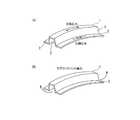
- a hat-shaped cross-sectional component in which both sides in the width direction of the top plate portion 1 are continuous to the flange portion 2 via the side wall portion 3, and the hat is curved so as to protrude toward the top plate portion 1 along the longitudinal direction.
- the product shape by press molding that is the object of the present embodiment is such that the main body portion 4 has the top plate portion 1 and the flange portion 2 continuous in the width direction via the side wall portion 3.
- the top plate portion 1 and the flange portion 2 are curved so as to protrude toward the top plate portion 1 along the longitudinal direction.
- FIG. 2 illustrates a case where the curved portion is formed to be biased to the left side.
- the curvature of the curvature along the longitudinal direction formed in the top plate portion 1 and the flange portion 2 may be the same, but is different in the present embodiment.
- the overhanging portions 5 are continuous with both ends in the longitudinal direction of the top plate portion 1. Since the width of each overhang portion 5 is larger in the width direction than the width of the top plate portion 1, the top plate surface on the end side in the longitudinal direction of the product shape in the top view is L-shaped or T-shaped. It has become.
- FIG. 2 illustrates a T shape.
- the lower end portion of the vertical wall portion 6 is continuous with the longitudinal end portion of the flange portion 2.
- the vertical wall portion 6 rises to the top plate portion 1 side, and its upper end continues to the overhang portion 5.
- the main body 4 having a curved portion extends in the vertical direction with respect to the vertical wall 6. That is, the vertical wall portion 6 rises so as to face the longitudinal direction of the main body portion 4.
- a shape in which the vertical wall portion 6 exists only on one side in the longitudinal direction may be used.
- the method for manufacturing a press-formed product according to the present invention can be applied even to a product shape without the overhanging portion 5 and the vertical wall portion 6. Moreover, even if the top-plate part 1 and the flange part 2 are concave curved shapes at the top-plate part 1 side along a longitudinal direction, it is applicable.
- the method for manufacturing a press-formed product of the present embodiment includes a first step and a second step as a process for forming a flat metal plate into the product shape described above. .
- the trim processing (not shown) which trims the flange outer periphery.
- the trim processing may be performed before the first step, may be performed between the first step and the second step, or may be performed after the second step.
- the intermediate part is a part in a state where trimming of the outer periphery of the flange is performed.
- the top plate portion 1 and the flange portion 2 are flattened into a part shape having a hat-shaped cross section with a second curvature radius smaller than the curvature radius in the product shape, respectively, along the longitudinal direction. It is a process of manufacturing an intermediate part by press-molding a metal plate (blank material). Even a steel plate having a metal plate material strength of 590 MPa or more is applicable.
- the second curvature radius of the top plate portion 1 and the second curvature radius of the flange portion 2 are set to have different sizes.
- the longitudinal lengths of the top plate portion 1 and the flange portion 2 in the intermediate part manufactured in the first step are respectively the longitudinal lengths of the top plate portion 1 and the flange portion 2 in the product shape, respectively. It is preferable to have the same value.
- the same line length can be obtained by adjusting the line length of the vertical wall portion 6 that connects the flange portion 2 and the overhang portion 5, for example.
- each of the second curvature radii of the top plate portion 1 and the flange portion 2 is preferably such that the curvature radius after the spring back generated in the intermediate part after being molded in the first step is equal to or less than the curvature radius in the product shape.
- the curvature radius of the top plate portion 1 along the longitudinal direction of the top plate portion 1 in the product shape is defined as R1o
- the curvature radius R1 ′ along the longitudinal direction of the top plate portion 1 after the spring back in the intermediate part is defined as R1o
- the value of the second radius of curvature at the top plate 1 it is preferable to set the value of the second radius of curvature at the top plate 1 so that the value satisfies the following expression (1). That is, the intermediate part after the spring back is set to have a radius of curvature on the spring go side as compared with the product shape. 0.70 ⁇ (R1 ′ / R1o) ⁇ 1.00 (1)
- the curvature radius R2 ′ along the longitudinal direction of the flange portion 2 after springback in the intermediate part is expressed by the following formula (2) It is preferable to set the value of the second radius of curvature at the flange portion 2 so that the value satisfies the above. That is, the intermediate part after the spring back is set to have a radius of curvature on the spring go side as compared with the product shape. 0.70 ⁇ (R2 ′ / R2o) ⁇ 1.00 (2)
- draw molding or foam molding may be applied to the molding in the first step.
- each radius of curvature after springback generated in each of the above intermediate parts may be obtained by calculation by performing CAE analysis or other simulation analysis by a computer, or may be obtained by actually making a test product and measuring it. good.
- the trim processing of a flange outer periphery is given.
- a known processing method such as shearing or laser cutting may be employed.
- the second step is a step of forming the intermediate part manufactured in the first step into a target product shape. Resto-like processing may be applied to the molding in the second step.
- the curvature radii of the top plate portion 1 and the flange portion 2 are each made smaller than the curvature radius of the product shape.
- the intermediate part obtained in the first step is press-molded so as to have a radius of curvature in the product shape to obtain a part having a target molded shape.
- the curvature radii of the top plate portion 1 and the flange portion 2 of the intermediate part after being released from the mold are used in the first step by springback depending on the value of the second curvature radius.
- the radius of curvature of the mold is slightly larger.
- the curvature radius of the top plate portion 1 and the flange portion 2 after the spring back of the intermediate part formed in the first step is smaller than the curvature radius in the product shape, preferably smaller than the curvature radius in the product shape.
- the metal plate to be pressed is a high-tensile material, but a steel plate or an aluminum plate may be used.
- the curvature radius of the top-plate part 1 in a product shape along a longitudinal direction and the curvature radius of a flange part may differ.
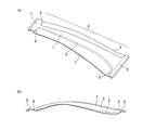
- FIG. 4 the conceptual diagram of each line length of the top-plate part and flange part in the side view shape of the 1st process of a curved component and a 2nd process is shown.
- the first step when the line length of the top plate portion 1 is formed to be shorter than the product shape (L1> L1 ′), there is a possibility that tensile stress is generated in the top plate portion 1 at the time of forming the second step. is there.
- the first process when the line length of the flange portion is formed to be longer than the product shape (L2 ⁇ L2 ′), there is a possibility that compressive stress is generated in the flange portion during the molding of the second step. Therefore, it is desirable that the line lengths of the top plate portion 1 and the flange portion after molding in the first step and after molding in the second step are the same or substantially the same.
- the molding of the first step by molding the respective curvature radii of the top plate portion 1 and the flange portion 2 of the intermediate part after the spring back to be equal to or less than the curvature radii in the product shape, In the restric molding, a small compressive stress is generated in the top plate portion 1 and a small tensile stress is generated in the flange portion 2. As a result, the stress difference is reduced, the amount of springback is reduced, and the sensitivity of the material strength can be reduced when the material strength fluctuates.
- the curvature radius of the top plate portion 1 after the springback is R1 ′
- the top plate portion 1 in the product shape The ratio with the radius of curvature R1o is preferably set in the range of 0.70 ⁇ (R1 ′ / R1o) ⁇ 1.00.
- the ratio of the radius of curvature R2o of the flange portion 2 in the product is 0.70 ⁇ (R2 ′ / R2o) ⁇ 1.00. It is preferable to set within the range.
- (R1 ′ / R1o) and (R2 ′ / R2o) are smaller than 0.7, an excessive compressive stress is applied to the top plate 1 at the bottom dead center of the mold in the second step. Excessive tensile stress is generated in 2 and a large spring go may occur in the press-formed product.
- the method for manufacturing a press-formed product of the present embodiment even when a high-tensile material is used for the metal plate, the spring back in a side view, that is, the camber back and the camber, without complicating the mold.
- the material strength sensitivity of the bag can be greatly reduced.
- the manufacturing method of the press-formed product of this embodiment is excellent in shape freezing property and material strength sensitivity.
- the present embodiment even when the material strength fluctuates, a part with high dimensional accuracy is obtained, which leads to an improvement in yield.
- a hat-shaped cross-sectional part to make a vehicle body structural part, it is possible to easily assemble the part.
- the curvature radii R1 and R2 of the top plate portion 1 and the flange portion 2 before the spring back are 1655 [mm] and 1596 [ mm]
- the curvature radii R1 ′ and R2 ′ of the top plate portion 1 and the flange portion 2 after the spring back were 1875 [mm] and 1793 [mm], respectively.
- the curvature radius magnification of each of the top plate portion 1 and the flange portion 2 in the first step is calculated from the curvature radius before the spring back.
- the size was reduced and press molding analysis was performed.
- the press molding analysis was performed using the mold model in the first process produced above, and the spring back analysis after the release of the press molded product molded to the bottom dead center of the molding was performed. Thereafter, a molding analysis was performed in which the molded product after the spring back was subjected to restric molding in the second step, and a spring back analysis was performed after the release of the press molded product molded to the bottom dead center.
- the curvature radius was changed from (R1 ′ / R1o) and (R2 ′ / R2o) to 0.7, 0.8, and 0.9 on the basis of conditions using a 980 MPa class material. Further, the amount of deviation from the product shape due to the spring back was best fit on the punch bottom seat surface, and was evaluated by the amount of deviation in the Z direction from the product shape at the top of the vehicle. Table 1 summarizes the press conditions and evaluation results.
- the maximum springback amount is 6.5 mm with a 1470 MPa class material. Moreover, when the difference between a 590 MPa class material and a 1470 MPa class material is compared, it turns out that it has reduced to the difference of 7.6 mm.
Priority Applications (4)
| Application Number | Priority Date | Filing Date | Title |
|---|---|---|---|
| KR1020187024623A KR102095143B1 (ko) | 2016-03-01 | 2017-01-16 | 프레스 성형품의 제조 방법 |
| JP2017523938A JP6176430B1 (ja) | 2016-03-01 | 2017-01-16 | プレス成形品の製造方法 |
| CN201780013609.4A CN108698105B (zh) | 2016-03-01 | 2017-01-16 | 冲压成型品的制造方法 |
| MX2018010509A MX369681B (es) | 2016-03-01 | 2017-01-16 | Método para la fabricación de producto moldeado por prensado. |
Applications Claiming Priority (2)
| Application Number | Priority Date | Filing Date | Title |
|---|---|---|---|
| JP2016039383 | 2016-03-01 | ||
| JP2016-039383 | 2016-03-01 |
Publications (1)
| Publication Number | Publication Date |
|---|---|
| WO2017149955A1 true WO2017149955A1 (ja) | 2017-09-08 |
Family
ID=59743734
Family Applications (1)
| Application Number | Title | Priority Date | Filing Date |
|---|---|---|---|
| PCT/JP2017/001211 WO2017149955A1 (ja) | 2016-03-01 | 2017-01-16 | プレス成形品の製造方法 |
Country Status (4)
| Country | Link |
|---|---|
| KR (1) | KR102095143B1 (ko) |
| CN (1) | CN108698105B (ko) |
| MX (1) | MX369681B (ko) |
| WO (1) | WO2017149955A1 (ko) |
Cited By (3)
| Publication number | Priority date | Publication date | Assignee | Title |
|---|---|---|---|---|
| WO2019026732A1 (ja) * | 2017-08-02 | 2019-02-07 | Jfeスチール株式会社 | プレス成形品の製造方法 |
| EP3760331A4 (en) * | 2018-02-28 | 2021-04-14 | JFE Steel Corporation | MANUFACTURING PROCESS FOR PRESSED COMPONENTS, PRESS FORMING DEVICE AND METAL PLATE FOR PRESS FORMING |
| JP2021186833A (ja) * | 2020-05-29 | 2021-12-13 | Jfeスチール株式会社 | プレス成形品の剛性評価方法、形状決定方法およびプレス成形品 |
Families Citing this family (1)
| Publication number | Priority date | Publication date | Assignee | Title |
|---|---|---|---|---|
| WO2020144995A1 (ja) * | 2019-01-11 | 2020-07-16 | Jfeスチール株式会社 | プレス成形方法、板状材料のブランク材、中間成形品、プレス成形品の製造方法およびプレス成形品 |
Citations (5)
| Publication number | Priority date | Publication date | Assignee | Title |
|---|---|---|---|---|
| JP2007118014A (ja) * | 2005-10-26 | 2007-05-17 | Nissan Motor Co Ltd | プレス成形方法およびプレス成形装置 |
| JP2007190588A (ja) * | 2006-01-19 | 2007-08-02 | Nippon Steel Corp | 金属板プレス成形方法 |
| JP2011206789A (ja) * | 2010-03-29 | 2011-10-20 | Kobe Steel Ltd | プレス成形方法 |
| JP2013063462A (ja) * | 2011-08-30 | 2013-04-11 | Jfe Steel Corp | 長手方向に湾曲したハット型部材のプレス成形方法 |
| WO2014106931A1 (ja) * | 2013-01-07 | 2014-07-10 | 新日鐵住金株式会社 | プレス成形品の製造方法 |
Family Cites Families (2)
| Publication number | Priority date | Publication date | Assignee | Title |
|---|---|---|---|---|
| JP2007286841A (ja) | 2006-04-14 | 2007-11-01 | Advanced Simulation Technology Of Mechanics R & D Co Ltd | 金型の見込みモデル生成装置および方法 |
| JP4757820B2 (ja) * | 2007-03-14 | 2011-08-24 | 新日本製鐵株式会社 | 形状凍結性に優れる多段プレス成形方法 |
-
2017
- 2017-01-16 CN CN201780013609.4A patent/CN108698105B/zh active Active
- 2017-01-16 KR KR1020187024623A patent/KR102095143B1/ko active IP Right Grant
- 2017-01-16 WO PCT/JP2017/001211 patent/WO2017149955A1/ja active Application Filing
- 2017-01-16 MX MX2018010509A patent/MX369681B/es active IP Right Grant
Patent Citations (5)
| Publication number | Priority date | Publication date | Assignee | Title |
|---|---|---|---|---|
| JP2007118014A (ja) * | 2005-10-26 | 2007-05-17 | Nissan Motor Co Ltd | プレス成形方法およびプレス成形装置 |
| JP2007190588A (ja) * | 2006-01-19 | 2007-08-02 | Nippon Steel Corp | 金属板プレス成形方法 |
| JP2011206789A (ja) * | 2010-03-29 | 2011-10-20 | Kobe Steel Ltd | プレス成形方法 |
| JP2013063462A (ja) * | 2011-08-30 | 2013-04-11 | Jfe Steel Corp | 長手方向に湾曲したハット型部材のプレス成形方法 |
| WO2014106931A1 (ja) * | 2013-01-07 | 2014-07-10 | 新日鐵住金株式会社 | プレス成形品の製造方法 |
Cited By (8)
| Publication number | Priority date | Publication date | Assignee | Title |
|---|---|---|---|---|
| WO2019026732A1 (ja) * | 2017-08-02 | 2019-02-07 | Jfeスチール株式会社 | プレス成形品の製造方法 |
| JP2019025533A (ja) * | 2017-08-02 | 2019-02-21 | Jfeスチール株式会社 | プレス成形品の製造方法 |
| EP3663012A4 (en) * | 2017-08-02 | 2020-06-17 | JFE Steel Corporation | PRESS MOLDED ARTICLE MANUFACTURING METHOD |
| US11052444B2 (en) | 2017-08-02 | 2021-07-06 | Jfe Steel Corporation | Method for manufacturing press formed product |
| EP3760331A4 (en) * | 2018-02-28 | 2021-04-14 | JFE Steel Corporation | MANUFACTURING PROCESS FOR PRESSED COMPONENTS, PRESS FORMING DEVICE AND METAL PLATE FOR PRESS FORMING |
| US11628486B2 (en) | 2018-02-28 | 2023-04-18 | Jfe Steel Corporation | Production method for pressed components, press forming device, and metal sheet for press forming |
| JP2021186833A (ja) * | 2020-05-29 | 2021-12-13 | Jfeスチール株式会社 | プレス成形品の剛性評価方法、形状決定方法およびプレス成形品 |
| JP7264116B2 (ja) | 2020-05-29 | 2023-04-25 | Jfeスチール株式会社 | プレス成形品の剛性評価方法、形状決定方法およびプレス成形品の製造方法 |
Also Published As
| Publication number | Publication date |
|---|---|
| CN108698105B (zh) | 2020-05-12 |
| CN108698105A (zh) | 2018-10-23 |
| MX2018010509A (es) | 2018-11-09 |
| KR102095143B1 (ko) | 2020-03-30 |
| KR20180105216A (ko) | 2018-09-27 |
| MX369681B (es) | 2019-11-15 |
Similar Documents
| Publication | Publication Date | Title |
|---|---|---|
| JP6512191B2 (ja) | 金型の設計方法およびプレス成形品の製造方法 | |
| JP6515961B2 (ja) | プレス成形品の製造方法 | |
| CN109562427B (zh) | 冲压成型品的制造方法 | |
| JP6504130B2 (ja) | プレス成形品の製造方法 | |
| WO2017149955A1 (ja) | プレス成形品の製造方法 | |
| RU2654403C2 (ru) | Образованное штамповкой изделие, автомобильный конструктивный элемент, включающий в себя изделие, способ изготовления и устройство для изготовления образованного штамповкой изделия | |
| WO2016171229A1 (ja) | プレス成形品の製造方法、プレス成形品及びプレス装置 | |
| KR102083108B1 (ko) | 프레스 성형품의 제조 방법 | |
| JP6094699B2 (ja) | プレス成形品の製造方法、プレス成形品及びプレス装置 | |
| JP6176430B1 (ja) | プレス成形品の製造方法 | |
| US11260443B2 (en) | Method for manufacturing press formed product | |
| JP6176429B1 (ja) | プレス成形品の製造方法 | |
| JP6112226B2 (ja) | プレス成形方法、及びプレス成形部品の製造方法 | |
| JP6493331B2 (ja) | プレス成形品の製造方法 | |
| WO2020090153A1 (ja) | プレス成形部品及びその製造方法 |
Legal Events
| Date | Code | Title | Description |
|---|---|---|---|
| ENP | Entry into the national phase |
Ref document number: 2017523938 Country of ref document: JP Kind code of ref document: A |
|
| ENP | Entry into the national phase |
Ref document number: 20187024623 Country of ref document: KR Kind code of ref document: A |
|
| WWE | Wipo information: entry into national phase |
Ref document number: 1020187024623 Country of ref document: KR |
|
| WWE | Wipo information: entry into national phase |
Ref document number: MX/A/2018/010509 Country of ref document: MX |
|
| NENP | Non-entry into the national phase |
Ref country code: DE |
|
| 121 | Ep: the epo has been informed by wipo that ep was designated in this application |
Ref document number: 17759427 Country of ref document: EP Kind code of ref document: A1 |
|
| 122 | Ep: pct application non-entry in european phase |
Ref document number: 17759427 Country of ref document: EP Kind code of ref document: A1 |