WO2017146090A1 - 交流電動機の制御装置 - Google Patents
交流電動機の制御装置 Download PDFInfo
- Publication number
- WO2017146090A1 WO2017146090A1 PCT/JP2017/006560 JP2017006560W WO2017146090A1 WO 2017146090 A1 WO2017146090 A1 WO 2017146090A1 JP 2017006560 W JP2017006560 W JP 2017006560W WO 2017146090 A1 WO2017146090 A1 WO 2017146090A1
- Authority
- WO
- WIPO (PCT)
- Prior art keywords
- order
- current
- vector
- conversion
- motor
- Prior art date
- Legal status (The legal status is an assumption and is not a legal conclusion. Google has not performed a legal analysis and makes no representation as to the accuracy of the status listed.)
- Ceased
Links
Images


Classifications
-
- H—ELECTRICITY
- H02—GENERATION; CONVERSION OR DISTRIBUTION OF ELECTRIC POWER
- H02P—CONTROL OR REGULATION OF ELECTRIC MOTORS, ELECTRIC GENERATORS OR DYNAMO-ELECTRIC CONVERTERS; CONTROLLING TRANSFORMERS, REACTORS OR CHOKE COILS
- H02P21/00—Arrangements or methods for the control of electric machines by vector control, e.g. by control of field orientation
- H02P21/22—Current control, e.g. using a current control loop
-
- H—ELECTRICITY
- H02—GENERATION; CONVERSION OR DISTRIBUTION OF ELECTRIC POWER
- H02P—CONTROL OR REGULATION OF ELECTRIC MOTORS, ELECTRIC GENERATORS OR DYNAMO-ELECTRIC CONVERTERS; CONTROLLING TRANSFORMERS, REACTORS OR CHOKE COILS
- H02P27/00—Arrangements or methods for the control of AC motors characterised by the kind of supply voltage
- H02P27/04—Arrangements or methods for the control of AC motors characterised by the kind of supply voltage using variable-frequency supply voltage, e.g. inverter or converter supply voltage
- H02P27/06—Arrangements or methods for the control of AC motors characterised by the kind of supply voltage using variable-frequency supply voltage, e.g. inverter or converter supply voltage using DC to AC converters or inverters
- H02P27/08—Arrangements or methods for the control of AC motors characterised by the kind of supply voltage using variable-frequency supply voltage, e.g. inverter or converter supply voltage using DC to AC converters or inverters with pulse width modulation
Definitions
- This disclosure relates to an AC motor control technique for controlling energization of a multiphase AC motor by current feedback control.
- the motor control device disclosed in Patent Document 1 converts a high-order component of an actual current into a direct current by high-order dq conversion, and performs feedback control on a high-order current command value set to zero.
- the higher-order dq-axis current control unit performs feedback control by performing proportional-integral calculation on each of the d-axis and q-axis, as in the fundamental wave current control. Guessed.
- the phase of the voltage vector and the current vector on the dq axis coordinates do not match, and there is a phase difference. When this phase difference increases, motor control may become unstable depending on the structure and characteristics of the AC motor.
- This disclosure aims to provide a control technique for an AC motor that stabilizes control by matching the phases of a high-order voltage vector and a high-order current vector.
- An AC motor control device that is an aspect of the technology of the present disclosure includes an inverter (40) that supplies electric power converted by operations of a plurality of switching elements (41-46) to a multiphase AC motor (80), and an AC A current controller (30) for controlling energization of the electric motor.
- the current controller calculates a drive signal for driving the inverter by “fundamental wave current control” and “higher order current control”.
- the “fundamental wave current control” is a control for making the primary component of the fed back actual current coincide with the fundamental wave current command vector on the dq coordinate.
- “High-order current control” is control in which one or more high-order components of a specific order extracted from the fed back actual current are made to coincide with a high-order current command vector on the high-order dq coordinate.
- the current controller includes a high-order voltage command calculation unit (55, 75) and a high-order vector conversion unit (57, 77).
- the high-order voltage command calculation unit calculates a high-order voltage command vector by feedback control that matches the high-order dq conversion value of the high-order component of a specific order extracted from the actual current with the high-order dq-axis current command value. .
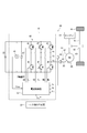
- FIG. 1 illustrates a system including one MG.
- the MG drive system 99 mounted on the hybrid vehicle converts the DC power of the battery 25, which is a chargeable / dischargeable secondary battery, into three-phase AC power by the inverter 40.
- the MG drive system 99 supplies three-phase AC power to the MG 80 and drives the MG 80.
- the MG control device 10 of the MG drive system 99 includes a current controller 30 and an inverter 40. Note that the MG control device 10 according to the present embodiment can also be applied to an MG drive system including two or more MGs.
- the MG80 is, for example, a permanent magnet type synchronous three-phase AC motor.
- the MG 80 is mounted on a hybrid vehicle including the engine 91.
- the MG 80 has both a function as an electric motor and a function as a generator.
- the MG 80 has a function as an electric motor that generates torque for driving the drive wheels 95.
- the MG 80 has a function as a generator that recovers energy by power generation from torque transmitted from the engine 91 and the drive wheels 95.
- the MG 80 is connected to the axle 94 via a gear 93 such as a transmission.
- the torque generated by the MG 80 rotates the axle 94 via the gear 93. Thereby, the driving wheel 95 is driven.
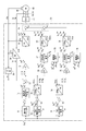
- the configuration and operation of the current controller 30 will be described with reference to FIGS.
- the current controller 30 is constituted by a microcomputer or the like, and includes a CPU, a ROM, an I / O, and a bus line for connecting them.
- the current controller 30 executes control (control by software processing) by the CPU executing a program stored in advance in a ROM or the like, or control by a dedicated electronic circuit (control by hardware processing).
- the current or voltage in the dq axis coordinates may be expressed as “current value or voltage value” or “current vector or voltage vector”.
- value attention is paid to each of a d-axis current value (or voltage value) that is a scalar quantity and a q-axis current value (or voltage value) that is a scalar quantity.
- vector attention is paid to a vector whose amplitude and phase are defined on coordinates.
- vector is used to refer to the phase.
- vector may be used for all dq-axis currents or dq-axis voltages.
- value is used unless the “vector” is clearly appropriate.
- the actual current dq conversion unit 36 Based on the electrical angle ⁇ e detected by the position sensor 85, the actual current dq conversion unit 36 converts the phase currents Iv and Iw of the fixed coordinate system detected by the current sensors 62 and 63 into the dq axis currents Id and Iq of the rotational coordinate system. Convert coordinates. The dq-axis currents Id and Iq are fed back to the fundamental current deviation calculation unit 13 as actual currents that are actually energized in the MG 80.
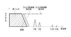
- phase current quintic component and the phase current seventh-order component are superimposed on the phase current primary component.
- (6n ⁇ 1) order components such as 11th order, 13th order, 17th order, 19th order, etc. are superposed in addition to 5th order and 7th order.
- the eleventh-order or higher components are omitted, and only the phase current quintic component and the phase current seventh-order component are referred to.
- the phase current quintic component and the phase current seventh order component are converted into a dq axis current sixth order component by dq conversion.
- a negative order is defined and terms such as “phase current ( ⁇ 5) order” and “dq axis ( ⁇ 6) order” are used.
- the positive and negative orders are not distinguished and are represented by absolute values.
- the fundamental wave current deviation calculation unit 13 is a difference between the fundamental wave current command values Id * and Iq * generated by the fundamental wave current command generation unit 12 and the actual currents Id and Iq fed back from the actual current dq conversion unit 36.
- the fundamental wave current deviations ⁇ Id and ⁇ Iq are calculated.
- the fundamental current deviations ⁇ Id and ⁇ Iq are considered to correspond to the sixth-order component of the dq coordinate system, as will be described later.
- the fundamental wave voltage command calculation unit 15 is configured by a PI controller, for example.
- the fundamental wave voltage command calculation unit 15 calculates fundamental wave dq-axis voltage command values Vd * and Vq * by PI control calculation so that the fundamental current deviations ⁇ Id and ⁇ Iq converge to 0, respectively.
- the three-phase conversion unit 18 converts the fundamental wave dq-axis voltage command values Vd * and Vq * into the three-phase voltage command values Vu * , Vv * , and Vw * based on the electrical angle ⁇ e.
- the three-phase voltage command values “Vu * , Vv * , Vw * ” are expressed as “Vuvw * ”.
- the high-order three-phase voltage command values are similarly expressed as “Vuvw 5 ** , Vuvw 7 ** ”.
- the high-order voltage component superimposing unit 19 adds the fifth-order and seventh-order three-phase voltage command values Vuvw calculated by the control blocks of the fifth-order and seventh-order current control systems to the fundamental three-phase voltage command values Vuvw *. 5 ** and Vuvw 7 ** are superimposed.
- FIG. 2 for convenience of illustration, the fifth-order three-phase voltage command value Vuvw 5 ** and the seventh-order three-phase voltage command value Vuvw 7 ** are added, and then the three-phase voltage command value of the fundamental wave is added.
- An example of adding to Vuvw * is shown. That is, FIG. 2 shows an example in which three-phase voltage command values are added in two stages.
- the addition method is not limited to this. As other addition methods, addition may be performed in one step regardless of the order of addition.
- the control block between the high-order voltage component superimposing unit 19 and the inverter 40 is omitted.
- a voltage duty converter and a PWM signal generator are provided.
- the voltage duty converter converts the fundamental three-phase voltage command value Vuvw * into a command duty. In the calculation of this conversion, information on the inverter input voltage Vinv is used.
- the PWM signal generator calculates PWM signals UU, UL, VU, VL, WU, WL by PWM modulation based on the command duty, and outputs them to inverter 40. Since PWM control is a well-known technique, detailed description is omitted.
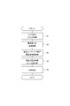
- FIG. 3 illustrates a schematic flow of fundamental wave current control processing executed by the control block of the fundamental wave current control system.
- the symbol “S” in the flowchart means a processing step (step).
- the command value filter 11 performs torque command filter processing (step S1).
- the fundamental wave current command generation unit 12 performs generation processing of the fundamental wave current command values Id * and Iq * in the dq coordinates based on the torque command value Trq * _f after the filtering process (step S2).
- the actual current dq converter 36 and the fundamental wave deviation calculator 13 perform current feedback processing on the fundamental current command values Id * and Iq * .
- the fundamental wave voltage command calculation unit 15 calculates the fundamental wave dq-axis voltage command values Vd * and Vq * (step S3).
- the three-phase conversion unit 18 performs coordinate conversion of the fundamental wave dq-axis voltage command values Vd * and Vq * and performs phase voltage calculation processing (step S4).
- the PWM signal generation unit performs PWM modulation (
- the control block of the fifth current control system includes a fifth current command generator 52, a fifth current deviation calculator 53, a fifth dq converter 54, a fifth voltage command calculator 55, a conversion amount setting unit 56, and a fifth voltage.
- a vector conversion unit 57 and a three-phase conversion unit 58 are included.
- the fifth-order current command generation unit 52 generates fifth-order dq-axis current command values Id 5 * and Iq 5 * by referring to a map (association data) according to the torque command value Trq * and the rotational speed ⁇ of the MG 80 . To do.
- the fifth-order dq converter 54 converts the fundamental wave current deviations ⁇ Id, ⁇ Iq (sixth-order components of the dq coordinate system) into higher-order dq coordinate systems based on “ ⁇ 5 ⁇ e” which is a ( ⁇ 5) multiple of the electrical angle ⁇ e.
- the high-order dq transform is performed to the fifth-order dq coordinate system.
- the fifth-order dq converter 54 extracts the phase current fifth-order component included in the actual current.
- orders such as “5th-order dq conversion” are expressed using absolute values of the orders of the fixed coordinate system. The meaning of the negative sign of “ ⁇ 5 ⁇ e” will be described later.
- the fifth-order current deviation calculation unit 53 includes the fifth-order dq-axis current command values Id 5 * and Iq 5 * generated by the fifth-order current command generation unit 52 and the fifth-order dq converted by the fifth-order dq conversion unit 54.
- the fifth current deviations ⁇ Id 5 and ⁇ Iq 5 which are the differences from the dq conversion value, are calculated.
- the value calculated by subtracting the actual currents Id and Iq is reflected in the output from the fundamental wave current deviation calculation unit 13. Therefore, the input from the fifth-order dq conversion unit 54 to the fifth-order current deviation calculation unit 53 is expressed by plus and minus the minus amount.
- the fifth voltage command calculation unit 55 is constituted by, for example, a PI controller.
- the fifth voltage command calculation unit 55 calculates the fifth voltage command vectors Vd 5 * and Vq 5 * by PI control calculation so that the fifth current deviations ⁇ Id 5 and ⁇ Iq 5 converge to 0, respectively.
- the fifth-order voltage vector conversion unit 57 executes “higher-order vector conversion processing” on the fifth-order dq coordinates for the fifth-order voltage command vectors Vd 5 * and Vq 5 * calculated by the fifth-order voltage command calculation unit 55. .
- the fifth voltage vector conversion unit 57 outputs the converted fifth dq axis voltage command vectors Vd 5 ** and Vq 5 ** .
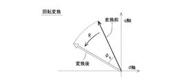
- the high-order vector conversion processing includes at least “rotational conversion” in which the phase of the fifth-order voltage command vectors Vd 5 * and Vq 5 * is rotated according to a predetermined rotation angle ⁇ 5 .
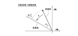
- the high-order vector conversion process may include “amplitude conversion” in which the amplitude of the fifth-order voltage command vectors Vd 5 * and Vq 5 * is multiplied by a gain G 5 other than one. In other words, in the high-order vector conversion process, when the gain G5 is 1 time, only the rotation conversion does not include the amplitude conversion.
- the rotation amount ⁇ 5 of rotation conversion and the gain G 5 of amplitude conversion which are conversion amounts of the high-order vector conversion processing, are set by the conversion amount setting unit 56.
- the conversion amount setting unit 56 sets the rotation angle ⁇ 5 of rotation conversion and the gain G 5 of amplitude conversion in accordance with the fundamental wave current command values Id * and Iq * and the rotation speed ⁇ . The technical significance of the high-order vector conversion process will be described later in detail.
- the three-phase conversion unit 58 calculates the dq-axis voltage command values Vd 5 ** and Vq 5 ** after the high-order vector conversion process based on “ ⁇ 5 ⁇ e” which is a ( ⁇ 5) multiple of the electrical angle ⁇ e. Coordinates are converted to the phase voltage command value Vuvw 5 ** .
- the fifth-order three-phase voltage command value Vuvw 5 ** is superimposed on the fundamental three-phase voltage command value Vuvw * by the higher-order voltage component superimposing unit 19.
- the dq conversion from the fixed coordinate system to the dq coordinate system is expressed by Expression (1).
- “ ⁇ d k ” in Expression (1) indicates a phase with respect to the d axis with respect to the k-th order component vector in the dq coordinate.
- “Ir k ” indicates the amplitude of the current vector of the k-th order component.
- Table 1 shows the correspondence between the orders in the fixed coordinate system and the orders in the dq coordinate system based on the formula (1).
- k 1 ⁇ 6n (n is a natural number) (2.1)
- the absolute value of k is expressed by Expression (2.2).
- 6n ⁇ 1 (n is a natural number) (2.2)
- the (k ⁇ 1) th order of the dq coordinate system corresponds to the kth order of the fixed coordinate system.
- the ( ⁇ 5) order of the fixed coordinate system corresponds to the ( ⁇ 6) order of the dq coordinate system
- the seventh order of the fixed coordinate system corresponds to the sixth order of the dq coordinate system. Therefore, the phase current ( ⁇ 5) order component and the phase current 7th order component contribute to torque sixth order variation in the three-phase AC motor.
- the angle input to the fifth-order dq conversion unit 54 and the three-phase conversion unit 58 in FIG. 2 is “ ⁇ 5 ⁇ e”.
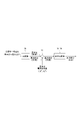
- FIG. 4 illustrates the relationship between the fixed coordinate system and the dq coordinate system for the fundamental wave.
- the phase order of the fundamental wave in the fixed coordinate system is the order of UVW.
- the amplitude of the dq axis current vector and Ir 1 the amplitude of the phase current is represented as ⁇ (2/3) ⁇ Ir 1 .
- the phase ⁇ d 1 of the dq-axis current vector corresponds to, for example, a phase at which the U-phase current becomes maximum when the electrical angle 0 ° in the fixed coordinates is used as a reference.
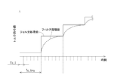
- the calculation cycle Tc_trq of the torque command generator 20 is set longer than the calculation cycle Tc_I of the current controller 30. Therefore, the calculated torque command is input stepwise to the current controller 30 that calculates with a relatively short period. Further, the responsiveness (current control calculation cycle) of the current controller 30 is faster than the torque command calculation cycle. Therefore, when the current controller 30 uses the input from the torque command generator 20 (input torque command) as it is for control, the actual torque is output from the MG 80 stepwise. As a result, for example, when applied to a hybrid vehicle, drivability may be affected.
- Patent Document 1 Japanese Patent No. 3809788 discloses a technique for extracting high-order components using a high-pass filter or a current response model.
- a high-pass filter is used, there remains a problem such as residual fundamental wave components.
- the current response model is used, the calculation load increases by the filter calculation process.
- a high-order component is calculated from the difference between the current command values Id * and Iq * generated from the torque command value Trq * _f after the filter processing by the command value filter 11 and the actual currents Id and Iq. Extract.
- the MG control apparatus 10 according to the present embodiment can avoid problems such as remaining fundamental wave components when a high-pass filter is used.
- the MG control device 10 according to the present embodiment can appropriately extract higher-order components without increasing the calculation load as in the case of using the current response model. As a result, the MG control device 10 according to the present embodiment can shorten the processing time.
- the d-axis voltage command value is calculated from the q-axis current deviation
- the q-axis voltage command value is calculated from the d-axis current deviation.
- the vector is rotated to correct the phase of the higher-order voltage vector such as the fifth order and the seventh order and the phase of the current vector.
- This high-order vector conversion process is executed for the high-order current vector deviation input to the fifth voltage command calculation unit 55 and the seventh voltage command calculation unit 75.
- the high-order vector conversion process is executed on the high-order voltage command vector calculated by feedback control.
- FIG. 8B illustrates a case where only rotation transformation (R) is performed in the high-order vector transformation processing.
- FIG. 8C illustrates a case where rotation conversion (R) and amplitude conversion (G) are simultaneously performed in the high-order vector conversion process.
- the rotation angle ⁇ k generally indicates rotational transformation for a k-th order vector.
- the fifth voltage command vectors Vd 5 * and Vq 5 * calculated by the fifth voltage command calculation unit 55 and the seventh order calculated by the seventh voltage command calculation unit 75 are used.
- the voltage command vectors Vd 7 * and Vq 7 * are rotated.
- the high-order vector conversion processing by the fifth-order voltage vector conversion unit 57 and the seventh-order voltage vector conversion unit 77 is expressed by Expression (4.1) and Expression (4.2) each including a rotation matrix.
- the phase difference ⁇ between the voltage vector and the current vector is caused by the inductance of the MG 80 and the induced voltage of the rotor. Therefore, the phase difference ⁇ depends on the operating state such as the current value and the rotational speed.
- the conversion amount setting units 56 and 76 according to the present embodiment map, for example, the relationship between the fundamental wave current command values Id * and Iq * and the rotation speed ⁇ , the phase difference ⁇ , and the amplitude ratio that are measured in advance. (Association data) is stored in advance.
- the high-order voltage command vectors Vd 5 * , Vq 5 * , Vd 7 * , and Vq 7 * are high-order vectors so that the phases of the high-order voltage vector and the high-order current vector coincide with each other. Perform the conversion process. Thereby, the MG control apparatus 10 according to the present embodiment can stabilize the motor control. The same applies to the case where high-order vector conversion processing is performed on the high-order current vector deviations ⁇ Id 5 , ⁇ Iq 5 , ⁇ Id 7 , ⁇ Iq 7 input to the fifth-order voltage command computation unit 55 and the seventh-order voltage command computation unit 75. It is.
- the rotation angles ⁇ 5 and ⁇ 7 of the rotation conversion and the gains G 5 and G 7 of the amplitude conversion are set according to the operation state such as the current value and the rotation speed.
- a current controller may not include a command value filter.
- a command value filter For example, when the processing capacity of the MG control apparatus has a margin, higher-order components may be extracted using a current response model.
- the torque command value Trq * input to the current controller may not include a high frequency component. In that case, a high-order component can be appropriately extracted from the difference between the current command values Id * and Iq * generated from the torque command value Trq * not including the high-frequency component and the actual currents Id and Iq.
- the AC motor driven in the system to which the technology of the present disclosure is applied may not have a function as a generator, like the MG 80 according to the above embodiment. Further, the AC motor is not limited to a permanent magnet type synchronous motor, and may be an induction motor or other synchronous motor.
- the number of phases of the rotating machine of the multiphase AC motor may be four or more. The specific order of the higher-order component to be extracted from the actual current differs depending on the number of phases.
- the control apparatus for an AC motor in the present disclosure is not limited to an MG drive system for a hybrid vehicle or an electric vehicle, but may be applied to an AC motor drive system for any application, such as for general machines.
- the present disclosure is not limited to the embodiment described above, and can be implemented in various forms without departing from the spirit of the disclosed technology.
- MG control device control device for AC motor
- 40 Inverter, 41-46... Switching element, 55, 75 ... 5th / 7th voltage command calculation unit (higher order voltage command calculation unit), 56, 76 ... conversion amount setting section, 57, 77... 5th / 7th voltage vector converter (higher order vector converter), 80: MG (AC motor).
Landscapes
- Engineering & Computer Science (AREA)
- Power Engineering (AREA)
- Control Of Ac Motors In General (AREA)
Priority Applications (2)
| Application Number | Priority Date | Filing Date | Title |
|---|---|---|---|
| US16/079,727 US10432123B2 (en) | 2016-02-24 | 2017-02-22 | Control apparatus for AC motor |
| CN201780012997.4A CN108702117B (zh) | 2016-02-24 | 2017-02-22 | 交流电动机的控制装置 |
Applications Claiming Priority (2)
| Application Number | Priority Date | Filing Date | Title |
|---|---|---|---|
| JP2016032899A JP6540538B2 (ja) | 2016-02-24 | 2016-02-24 | 交流電動機の制御装置 |
| JP2016-032899 | 2016-02-24 |
Publications (1)
| Publication Number | Publication Date |
|---|---|
| WO2017146090A1 true WO2017146090A1 (ja) | 2017-08-31 |
Family
ID=59685256
Family Applications (1)
| Application Number | Title | Priority Date | Filing Date |
|---|---|---|---|
| PCT/JP2017/006560 Ceased WO2017146090A1 (ja) | 2016-02-24 | 2017-02-22 | 交流電動機の制御装置 |
Country Status (4)
| Country | Link |
|---|---|
| US (1) | US10432123B2 (enExample) |
| JP (1) | JP6540538B2 (enExample) |
| CN (1) | CN108702117B (enExample) |
| WO (1) | WO2017146090A1 (enExample) |
Cited By (2)
| Publication number | Priority date | Publication date | Assignee | Title |
|---|---|---|---|---|
| CN111049439A (zh) * | 2018-10-12 | 2020-04-21 | 通用汽车环球科技运作有限责任公司 | 用于弱磁的车辆的马达控制系统及方法 |
| WO2024105859A1 (ja) * | 2022-11-17 | 2024-05-23 | 三菱電機株式会社 | インバータ制御装置、モータ駆動装置、送風機及び空気調和機 |
Families Citing this family (7)
| Publication number | Priority date | Publication date | Assignee | Title |
|---|---|---|---|---|
| CN107994827B (zh) * | 2017-11-17 | 2020-11-03 | 美的集团股份有限公司 | 电机驱动系统和采样相电流相电压的同步计算方法、装置 |
| JP6638173B2 (ja) * | 2018-03-30 | 2020-01-29 | 本田技研工業株式会社 | 電力変換装置 |
| CN110308326A (zh) * | 2019-07-15 | 2019-10-08 | 国网山西省电力公司电力科学研究院 | 一种可提高开环测相算法抗噪性能的方法 |
| EP4033654B1 (en) * | 2019-11-13 | 2025-01-08 | Guangdong Midea White Home Appliance Technology Innovation Center Co., Ltd. | Commutation error compensation method and apparatus for electric motor, and storage medium |
| KR102819791B1 (ko) * | 2020-05-11 | 2025-06-16 | 현대모비스 주식회사 | 단일 전류 센서를 이용한 위치 센서리스 모터 제어 시스템 |
| GB2595492B (en) | 2020-05-28 | 2022-08-17 | Yasa Ltd | A controller for an axial flux machine and method |
| JP7556341B2 (ja) * | 2021-01-15 | 2024-09-26 | トヨタ自動車株式会社 | 電動車両の制御装置 |
Citations (4)
| Publication number | Priority date | Publication date | Assignee | Title |
|---|---|---|---|---|
| JP2003153575A (ja) * | 2001-11-15 | 2003-05-23 | Nissan Motor Co Ltd | モーター制御装置 |
| JP2010063221A (ja) * | 2008-09-02 | 2010-03-18 | Toyota Industries Corp | モータ制御装置 |
| WO2012133220A1 (ja) * | 2011-03-25 | 2012-10-04 | アイシン・エィ・ダブリュ株式会社 | 制御装置 |
| JP2013066367A (ja) * | 2011-08-31 | 2013-04-11 | Denso Corp | 回転機の制御装置 |
Family Cites Families (10)
| Publication number | Priority date | Publication date | Assignee | Title |
|---|---|---|---|---|
| EP1211798B1 (en) | 2000-11-22 | 2018-01-10 | Nissan Motor Co., Ltd. | Motor control apparatus and motor control method |
| JP4234359B2 (ja) * | 2002-06-27 | 2009-03-04 | オークマ株式会社 | 同期電動機の制御装置 |
| US7230403B2 (en) * | 2003-04-29 | 2007-06-12 | International Rectifier Corporation | System and method for elimination of DC offset feedback in AC drives |
| JP5120586B2 (ja) * | 2005-06-28 | 2013-01-16 | 株式会社デンソー | 界磁巻線型同期機 |
| FR2889370B1 (fr) * | 2005-07-29 | 2007-09-07 | Valeo Equip Electr Moteur | Procede de commande d'un onduleur de tension polyphase |
| JP6000801B2 (ja) * | 2012-10-24 | 2016-10-05 | ジョンソンコントロールズ ヒタチ エア コンディショニング テクノロジー(ホンコン)リミテッド | モータ制御装置、およびそれを用いた空気調和機 |
| KR101304665B1 (ko) * | 2013-05-08 | 2013-09-06 | 영남대학교 산학협력단 | 교류 모터의 제어 방법 |
| US9419553B2 (en) * | 2014-07-25 | 2016-08-16 | Denso Corporation | Apparatus for controlling rotary machine |
| CN104579080A (zh) * | 2015-02-10 | 2015-04-29 | 南车株洲电力机车研究所有限公司 | 一种永磁同步电机转矩脉动抑制方法 |
| JP2017153226A (ja) | 2016-02-24 | 2017-08-31 | 株式会社デンソー | 交流電動機の制御装置 |
-
2016
- 2016-02-24 JP JP2016032899A patent/JP6540538B2/ja active Active
-
2017
- 2017-02-22 WO PCT/JP2017/006560 patent/WO2017146090A1/ja not_active Ceased
- 2017-02-22 CN CN201780012997.4A patent/CN108702117B/zh active Active
- 2017-02-22 US US16/079,727 patent/US10432123B2/en active Active
Patent Citations (4)
| Publication number | Priority date | Publication date | Assignee | Title |
|---|---|---|---|---|
| JP2003153575A (ja) * | 2001-11-15 | 2003-05-23 | Nissan Motor Co Ltd | モーター制御装置 |
| JP2010063221A (ja) * | 2008-09-02 | 2010-03-18 | Toyota Industries Corp | モータ制御装置 |
| WO2012133220A1 (ja) * | 2011-03-25 | 2012-10-04 | アイシン・エィ・ダブリュ株式会社 | 制御装置 |
| JP2013066367A (ja) * | 2011-08-31 | 2013-04-11 | Denso Corp | 回転機の制御装置 |
Cited By (2)
| Publication number | Priority date | Publication date | Assignee | Title |
|---|---|---|---|---|
| CN111049439A (zh) * | 2018-10-12 | 2020-04-21 | 通用汽车环球科技运作有限责任公司 | 用于弱磁的车辆的马达控制系统及方法 |
| WO2024105859A1 (ja) * | 2022-11-17 | 2024-05-23 | 三菱電機株式会社 | インバータ制御装置、モータ駆動装置、送風機及び空気調和機 |
Also Published As
| Publication number | Publication date |
|---|---|
| JP2017153227A (ja) | 2017-08-31 |
| CN108702117B (zh) | 2021-05-28 |
| CN108702117A (zh) | 2018-10-23 |
| US20190052211A1 (en) | 2019-02-14 |
| JP6540538B2 (ja) | 2019-07-10 |
| US10432123B2 (en) | 2019-10-01 |
Similar Documents
| Publication | Publication Date | Title |
|---|---|---|
| JP6540538B2 (ja) | 交流電動機の制御装置 | |
| JP7013342B2 (ja) | 多相電動機駆動装置 | |
| US7034493B2 (en) | Motor control apparatus and motor control method | |
| CN101803172B (zh) | 电动机控制装置和驱动装置 | |
| CN101212196B (zh) | 永久磁铁电动机的无脉动控制装置 | |
| JP5888567B2 (ja) | 交流電動機の制御装置 | |
| US9112436B2 (en) | System for controlling controlled variable of rotary machine | |
| JP6036322B2 (ja) | モータ駆動装置および真空ポンプ | |
| US20170294863A1 (en) | Control apparatus for ac motor | |
| JP2014050150A (ja) | 3相回転機の制御装置 | |
| CN107980202A (zh) | 驱动系统以及逆变器装置 | |
| CN104025449A (zh) | 交流旋转电机的控制装置、以及包括该控制装置的电动助力转向装置 | |
| WO2019102539A1 (ja) | 回転電機制御装置及び電動車両 | |
| JP2004032944A (ja) | 同期電動機の制御装置及び同期電動機 | |
| Singh et al. | Performance investigation of permanent magnet synchronous motor drive using vector controlled technique | |
| JP2004048933A (ja) | Dcブラシレスモータの制御装置 | |
| JP7092257B2 (ja) | 回転電機制御システム | |
| JP2017034760A (ja) | モータの制御装置 | |
| CN111919379B (zh) | 马达控制装置、电动车辆 | |
| WO2017146089A1 (ja) | 交流電動機の制御装置 | |
| JP2008048505A (ja) | 3相回転機の制御装置 | |
| JP2004080975A (ja) | 電動機の制御装置 | |
| JP5444983B2 (ja) | 回転機の制御装置 | |
| JPH09191697A (ja) | 交流電動機のベクトル制御装置 | |
| CN110392976A (zh) | 马达控制方法、马达控制系统以及电动助力转向系统 |
Legal Events
| Date | Code | Title | Description |
|---|---|---|---|
| NENP | Non-entry into the national phase |
Ref country code: DE |
|
| 121 | Ep: the epo has been informed by wipo that ep was designated in this application |
Ref document number: 17756528 Country of ref document: EP Kind code of ref document: A1 |
|
| 122 | Ep: pct application non-entry in european phase |
Ref document number: 17756528 Country of ref document: EP Kind code of ref document: A1 |