WO2017145495A1 - 電子部品搬送装置および電子部品検査装置 - Google Patents
電子部品搬送装置および電子部品検査装置 Download PDFInfo
- Publication number
- WO2017145495A1 WO2017145495A1 PCT/JP2016/086645 JP2016086645W WO2017145495A1 WO 2017145495 A1 WO2017145495 A1 WO 2017145495A1 JP 2016086645 W JP2016086645 W JP 2016086645W WO 2017145495 A1 WO2017145495 A1 WO 2017145495A1
- Authority
- WO
- WIPO (PCT)
- Prior art keywords
- unit
- axis
- electronic component
- output signal
- encoder
- Prior art date
- Legal status (The legal status is an assumption and is not a legal conclusion. Google has not performed a legal analysis and makes no representation as to the accuracy of the status listed.)
- Ceased
Links
Images




Classifications
-
- G—PHYSICS
- G01—MEASURING; TESTING
- G01R—MEASURING ELECTRIC VARIABLES; MEASURING MAGNETIC VARIABLES
- G01R31/00—Arrangements for testing electric properties; Arrangements for locating electric faults; Arrangements for electrical testing characterised by what is being tested not provided for elsewhere
- G01R31/28—Testing of electronic circuits, e.g. by signal tracer
- G01R31/2851—Testing of integrated circuits [IC]
- G01R31/2855—Environmental, reliability or burn-in testing
- G01R31/286—External aspects, e.g. related to chambers, contacting devices or handlers
- G01R31/2865—Holding devices, e.g. chucks; Handlers or transport devices
- G01R31/2867—Handlers or transport devices, e.g. loaders, carriers, trays
-
- H—ELECTRICITY
- H10—SEMICONDUCTOR DEVICES; ELECTRIC SOLID-STATE DEVICES NOT OTHERWISE PROVIDED FOR
- H10P—GENERIC PROCESSES OR APPARATUS FOR THE MANUFACTURE OR TREATMENT OF DEVICES COVERED BY CLASS H10
- H10P72/00—Handling or holding of wafers, substrates or devices during manufacture or treatment thereof
- H10P72/06—Apparatus for monitoring, sorting, marking, testing or measuring
- H10P72/0606—Position monitoring, e.g. misposition detection or presence detection
-
- G—PHYSICS
- G01—MEASURING; TESTING
- G01R—MEASURING ELECTRIC VARIABLES; MEASURING MAGNETIC VARIABLES
- G01R31/00—Arrangements for testing electric properties; Arrangements for locating electric faults; Arrangements for electrical testing characterised by what is being tested not provided for elsewhere
- G01R31/28—Testing of electronic circuits, e.g. by signal tracer
- G01R31/2851—Testing of integrated circuits [IC]
- G01R31/2886—Features relating to contacting the IC under test, e.g. probe heads; chucks
- G01R31/2891—Features relating to contacting the IC under test, e.g. probe heads; chucks related to sensing or controlling of force, position, temperature
-
- H—ELECTRICITY
- H10—SEMICONDUCTOR DEVICES; ELECTRIC SOLID-STATE DEVICES NOT OTHERWISE PROVIDED FOR
- H10P—GENERIC PROCESSES OR APPARATUS FOR THE MANUFACTURE OR TREATMENT OF DEVICES COVERED BY CLASS H10
- H10P72/00—Handling or holding of wafers, substrates or devices during manufacture or treatment thereof
- H10P72/10—Handling or holding of wafers, substrates or devices during manufacture or treatment thereof using carriers specially adapted therefor, e.g. front opening unified pods [FOUP]
- H10P72/16—Trays for chips
-
- H—ELECTRICITY
- H10—SEMICONDUCTOR DEVICES; ELECTRIC SOLID-STATE DEVICES NOT OTHERWISE PROVIDED FOR
- H10P—GENERIC PROCESSES OR APPARATUS FOR THE MANUFACTURE OR TREATMENT OF DEVICES COVERED BY CLASS H10
- H10P72/00—Handling or holding of wafers, substrates or devices during manufacture or treatment thereof
- H10P72/70—Handling or holding of wafers, substrates or devices during manufacture or treatment thereof for supporting or gripping
- H10P72/76—Handling or holding of wafers, substrates or devices during manufacture or treatment thereof for supporting or gripping using mechanical means, e.g. clamps or pinches
- H10P72/7604—Handling or holding of wafers, substrates or devices during manufacture or treatment thereof for supporting or gripping using mechanical means, e.g. clamps or pinches the wafers being placed on a susceptor, stage or support
- H10P72/7618—Handling or holding of wafers, substrates or devices during manufacture or treatment thereof for supporting or gripping using mechanical means, e.g. clamps or pinches the wafers being placed on a susceptor, stage or support characterised by a movable susceptor, stage or support, others than those only rotating on their own vertical axis, e.g. susceptors on a rotating carrousel
-
- H—ELECTRICITY
- H10—SEMICONDUCTOR DEVICES; ELECTRIC SOLID-STATE DEVICES NOT OTHERWISE PROVIDED FOR
- H10P—GENERIC PROCESSES OR APPARATUS FOR THE MANUFACTURE OR TREATMENT OF DEVICES COVERED BY CLASS H10
- H10P72/00—Handling or holding of wafers, substrates or devices during manufacture or treatment thereof
- H10P72/70—Handling or holding of wafers, substrates or devices during manufacture or treatment thereof for supporting or gripping
- H10P72/78—Handling or holding of wafers, substrates or devices during manufacture or treatment thereof for supporting or gripping using vacuum or suction, e.g. Bernoulli chucks
Definitions
- the present invention relates to an electronic component conveying device and an electronic component inspection device.
- a plurality of IC devices are placed on the tray, and the tray is placed in the apparatus, whereby the tray is transported to the inspection section where inspection is performed by the transport section (gripping section).
- the IC device is placed on the tray, conveyed by the conveyance unit together with the tray after the inspection, and discharged outside the apparatus.
- the transport unit incorporates an encoder that detects position information of the transport unit.
- the position information detected by the encoder is transmitted to the control unit.
- the control unit controls the transport unit based on the transmitted position information.
- noise may be superimposed on the output signal of the position information of the conveyance unit output by the encoder due to the influence of electric power applied to members around the encoder, such as a motor and a piezo element. In this case, depending on the degree of noise, it becomes difficult to accurately detect the position information of the transport unit.
- the present invention has been made to solve at least a part of the problems described above, and can be realized as the following forms or application examples.
- An electronic component transport apparatus includes a gripping unit that grips an electronic component, A base portion in which the grip portion is movably disposed; A position detection unit that detects a relative position between the base and the gripping unit; A drive unit for driving the gripping unit; A control unit for controlling the driving of the driving unit; A waveform converting unit provided between the position detecting unit and the control unit and converting a waveform of an output signal output from the position detecting unit;
- control unit is electrically connected to the position detection unit via the waveform conversion unit.
- the waveform converting unit amplifies the voltage of the output signal. Thereby, it is possible to further reduce the influence when noise is superimposed on the output signal.
- the waveform conversion unit amplifies the voltage of the output signal to 2 to 10 times.
- the position detection unit is an encoder. Therefore, the position of the grip portion can be accurately detected.
- the electronic component transport apparatus it is preferable that a plurality of the drive units and the encoders are provided.
- the drive unit rotates an X-axis drive unit that drives the grip unit in the X-axis direction, a Y-axis drive unit that drives the grip unit in the Y-axis direction, and rotates the grip unit around the Z axis.
- the encoder includes an X-axis encoder that detects a position in the X-axis direction of the grip part driven by the X-axis drive part, and a position in the Y-axis direction of the grip part driven by the Y-axis drive part. It is preferable to have a Y-axis encoder for detecting the position and a Z-axis encoder for detecting a position around the Z-axis of the grip portion driven by the Z-axis drive unit.
- the X-axis drive unit and the X-axis encoder are X-axis units
- the Y-axis drive unit and the Y-axis encoder are Y-axis units
- the Z-axis drive unit When the Z-axis encoder is a Z-axis unit, It is preferable that a plurality of the X-axis unit, the Y-axis unit, and the Z-axis unit are provided. Thereby, the position of more grip parts can be detected accurately.
- the waveform converting unit has a function of converting the output signal into a signal capable of detecting an error.
- the waveform converters are electrically connected to each other, and one of the waveform converters is electrically connected to the control unit.
- the driving unit has a piezo actuator as a driving source. Thereby, the fine adjustment of the position of a holding part can be performed correctly.
- the electronic component transport device includes a support substrate that supports the grip portion,
- the waveform converting unit is preferably disposed on the support substrate.
- the waveform converter is installed as close to the encoder as possible. As a result, the position information of the grip portion can be detected more accurately.
- the grip portion is disposed in an inspection area where the electronic component is inspected.
- region can be detected correctly.
- the electronic component inspection apparatus of the present invention includes a gripping unit that grips an electronic component, A base portion in which the grip portion is movably disposed; A position detection unit that detects a relative position between the base and the gripping unit; A drive unit for driving the gripping unit; A control unit for controlling the driving of the driving unit; A waveform converter that is provided between the position detector and the controller and converts a waveform of an output signal output by the position detector; An inspection unit for inspecting the electronic component.
- FIG. 1 is a schematic perspective view of an electronic component inspection apparatus according to an embodiment of the present invention as viewed from the front side.
- FIG. 2 is a schematic plan view showing an operating state of the electronic component inspection apparatus shown in FIG.
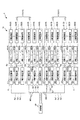
- FIG. 3 is a block diagram of the electronic component inspection apparatus shown in FIG.
- FIG. 4 is a side view of a device transport head provided in the electronic component inspection apparatus shown in FIG.
- FIG. 5 is a block diagram of the electronic component inspection apparatus shown in FIG.
- FIG. 6 is a graph showing the change over time of the output signal output from the relay board included in the electronic component inspection apparatus shown in FIG.
- FIG. 7 is a graph showing a change with time of an output signal output from an encoder provided in a conventional electronic component inspection apparatus.
- FIG. 8 is a perspective view showing a robot which is a modification of the electronic component conveying apparatus and the electronic component inspection apparatus of the present invention.
- FIGS. 1, 2, and 4 As an example of three axes that intersect with each other, three orthogonal axes are referred to as an X axis, a Y axis, and a Z axis. Further, the XY plane including the X axis and the Y axis is horizontal, and the Z axis is vertical.
- a direction parallel to the X axis is also referred to as “X direction”
- a direction parallel to the Y axis is also referred to as “Y direction”
- a direction parallel to the Z axis is also referred to as “Z direction”.
- the direction in which the arrow in each direction is directed is called “positive”, and the opposite direction is called “negative”.
- the term “horizontal” in the specification of the present application is not limited to complete horizontal, and includes a state slightly inclined (for example, less than about 5 °) with respect to the horizontal as long as transportation of electronic components is not hindered.
- the inspection apparatus 1 is an apparatus that, for example, conveys electronic components such as an IC device that is a BGA (Ball ⁇ Grid Array) package, and inspects and tests electrical characteristics (hereinafter simply referred to as “inspection”) during the conveyance process. .
- BGA All ⁇ Grid Array
- the inspection apparatus 1 determines the relative positions of the suction pad 173 as a gripping part for gripping the IC device 90, the support substrate 171 as a base part on which the suction pad 173 is movably disposed, and the support substrate 171 and the suction pad 173.
- the position detection unit 4 to detect, the drive unit 3 to drive the suction pad 173, the control unit 80 to control the drive of the drive unit 3, the inspection unit 16 to inspect the IC device 90, and the position detection unit 4 and control
- the relay board 5 is provided between the unit 80 and the waveform converting unit that converts the waveform of the output signal output from the position detecting unit 4, and the inspection unit 16 that inspects the IC device 90.
- the electronic component conveying apparatus 10 is an apparatus that conveys an electronic component, and includes a suction pad 173 as a grip portion that grips the IC device 90, a support substrate 171 as a base portion on which the suction pad 173 is movably disposed, and a support
- the position detection unit 4 that detects the relative position between the substrate 171 and the suction pad 173, the drive unit 3 that drives the suction pad 173, the control unit 80 that controls the drive of the drive unit 3, and the IC device 90 are inspected.
- the relay board 5 is provided between the inspection unit 16 and the position detection unit 4 and the control unit 80 and serves as a waveform conversion unit that converts the waveform of the output signal output from the position detection unit 4.
- IC device 90 an IC device is used as the electronic component
- the IC device 90 is placed on a placement member that is the tray 200.
- the inspection apparatus 1 includes a tray supply area A1, a device supply area (hereinafter simply referred to as “supply area”) A2, an inspection area A3, a device collection area A4 (hereinafter simply referred to as “collection area”), and a tray removal. It is divided into area A5. Then, the IC device 90 passes through the respective areas in the direction of the arrow ⁇ 90 from the tray supply area A1 to the tray removal area A5, and the inspection is performed in the intermediate inspection area A3. As described above, the inspection apparatus 1 includes the electronic component transport apparatus 10 (handler) that transports the IC device 90 in each region and the inspection unit 16 that performs inspection in the inspection region A3. In addition, the inspection apparatus 1 includes a monitor 300, a signal lamp 400, and an operation panel 700.
- the tray supply area A1 and the tray removal area A5 are arranged, that is, the lower side in FIG. 2 is the front side, and the inspection area A3 is arranged, that is, the upper side in FIG. The side is used as the back side.
- the tray supply area A1 is a material supply unit to which a tray 200 in which a plurality of untested IC devices 90 are arranged is supplied. In the tray supply area A1, a large number of trays 200 can be stacked.
- the supply area A2 is an area where a plurality of IC devices 90 on the tray 200 conveyed from the tray supply area A1 are supplied to the inspection area A3.
- tray transport mechanisms 11A and 11B that transport the tray 200 one by one in the horizontal direction are provided so as to straddle the tray supply area A1 and the supply area A2.
- the tray transport mechanism 11A is a moving unit that can move the tray 200 together with the IC device 90 placed on the tray 200 on the positive side in the Y direction, that is, the arrow ⁇ 11A in FIG. Thereby, the IC device 90 can be stably fed into the supply area A2.
- the tray transport mechanism 11B is a moving unit that can move the empty tray 200 to the negative side in the Y direction, that is, the arrow ⁇ 11B in FIG. Thereby, the empty tray 200 can be moved from the supply area A2 to the tray supply area A1.
- the supply region A2 is provided with a temperature adjustment unit (soak plate (English notation: soak plate, Chinese notation (example): temperature equalizing plate)) 12, a device transfer head 13, and a tray transfer mechanism 15. .
- the temperature adjustment unit 12 can place a plurality of IC devices 90 and collectively heat these IC devices 90, and is called a “soak plate”. With the soak plate, the IC device 90 before being inspected by the inspection unit 16 can be heated in advance and adjusted to a temperature suitable for the inspection (high temperature inspection). In the configuration shown in FIG. 2, two temperature adjusting units 12 are arranged and fixed in the Y direction. Then, the IC device 90 on the tray 200 carried in from the tray supply area A1 by the tray transport mechanism 11A is transported to any one of the temperature adjustment units 12.
- the device transport head 13 is supported so as to be movable in the X and Y directions and further in the Z direction within the supply area A2. As a result, the device transport head 13 transports the IC device 90 between the tray 200 loaded from the tray supply area A1 and the temperature adjustment unit 12, and between the temperature adjustment unit 12 and a device supply unit 14 described later. It is possible to carry the IC device 90.
- the movement of the device transport head 13 in the X direction is indicated by an arrow ⁇ 13X
- the movement of the device transport head 13 in the Y direction is indicated by an arrow ⁇ 13Y .
- Tray transporting mechanism 15 the positive side of the X direction empty tray 200 in a state where all of the IC devices 90 is removed in the feed region A2, i.e., a mechanism for conveying the arrow alpha 15 direction. After this conveyance, the empty tray 200 is returned from the supply area A2 to the tray supply area A1 by the tray conveyance mechanism 11B.
- the inspection area A3 is an area where the IC device 90 is inspected.
- an inspection unit 16 and a device transport head 17 are provided in the inspection area A3.
- a device supply unit 14 that moves so as to straddle the supply region A2 and the inspection region A3 and a device recovery unit 18 that moves so as to straddle the inspection region A3 and the recovery region A4 are also provided.
- the device supply unit 14 is configured as a mounting unit on which the IC device 90 temperature-adjusted by the temperature adjusting unit 12 is mounted and can transport the IC device 90 to the vicinity of the inspection unit 16. "Or simply" feed shuttle ".
- the device supply unit 14 between the supply region A2 and the inspection area A3 X direction i.e., are reciprocally movably supported along an arrow alpha 14 direction.
- two device supply units 14 are arranged in the Y direction, and the IC device 90 on the temperature adjustment unit 12 is transported to one of the device supply units 14.
- the device supply unit 14 is configured to be able to heat the IC device 90 placed on the device supply unit 14, similarly to the temperature adjustment unit 12.
- the IC device 90 whose temperature has been adjusted by the temperature adjustment unit 12 can be transported to the vicinity of the inspection unit 16 in the inspection region A3 while maintaining the temperature adjustment state.
- the device transport head 17 is an operation unit that grips the IC device 90 in which the temperature adjustment state is maintained and transports the IC device 90 in the inspection area A3.
- the device transport head 17 is supported so as to be reciprocally movable in the Y direction and the Z direction in the inspection area A3, and is a part of a mechanism called an “index arm”. Thereby, the device transport head 17 can transport and place the IC device 90 on the device supply unit 14 carried in from the supply area A2 onto the inspection unit 16.
- the reciprocating movement of the device transport head 17 in the Y direction is indicated by an arrow ⁇ 17Y .
- the device transport head 17 is supported so as to be reciprocally movable in the Y direction and the Z direction, but is not limited thereto, and may be supported so as to be reciprocally movable in the X direction.
- the device transport head 17 is configured to be able to heat the gripped IC device 90 in the same manner as the temperature adjustment unit 12. Thereby, the temperature adjustment state in the IC device 90 can be continuously maintained from the device supply unit 14 to the inspection unit 16.
- the inspection unit 16 is configured as a mounting unit that mounts an IC device 90 that is an electronic component and inspects / tests (inspects) the electrical characteristics of the IC device 90.
- the inspection unit 16 is provided with a plurality of probe pins that are electrically connected to the terminal unit of the IC device 90. Then, the IC device 90 can be inspected when the terminal portion of the IC device 90 and the probe pin are electrically connected, that is, contacted.
- the inspection of the IC device 90 is performed based on a program stored in the storage unit 83 (see FIG. 3) of the control unit 80. Note that, similarly to the temperature adjustment unit 12, the inspection unit 16 can also heat the IC device 90 to adjust the IC device 90 to a temperature suitable for the inspection.
- the inspection unit 16, the temperature adjustment unit 12, the device supply unit 14, and the device transport head 17 are each configured to be able to cool the IC device 90 in addition to being able to heat the IC device 90. May be.
- the device collection unit 18 is configured as a placement unit on which the IC device 90 that has been inspected by the inspection unit 16 is placed and can transport the IC device 90 to the collection region A4. Or simply called the “recovery shuttle”.
- two device collection units 18 are arranged in the Y direction, similarly to the device supply unit 14, and the IC device 90 on the inspection unit 16 is one of the device collection units 18. Are transported to and placed. Transport to the device collection unit 18 is performed by the device transport head 17.
- the collection area A4 is an area where a plurality of IC devices 90 that have been inspected are collected.
- a collection tray 19 In the collection area A4, a collection tray 19, a device conveyance head 20, and a tray conveyance mechanism 21 are provided.
- An empty tray 200 is also prepared in the collection area A4.
- the collection tray 19 is configured as a placement unit on which the IC device 90 inspected by the inspection unit 16 is placed, and is fixed so as not to move in the collection region A4. As a result, the inspected IC device 90 can be stably placed on the collection tray 19 even in the collection area A4 where a relatively large number of various movable parts such as the device transport head 20 are arranged. Become. In the configuration shown in FIG. 2, three collection trays 19 are arranged along the X direction.
- This empty tray 200 is also a placement unit on which the IC device 90 inspected by the inspection unit 16 is placed. Then, the IC device 90 on the device recovery unit 18 that has moved to the recovery area A4 is conveyed and placed on either the recovery tray 19 or the empty tray 200. Thereby, the IC device 90 is classified and collected for each inspection result.
- the device transport head 20 is supported so as to be movable in the X and Y directions and further in the Z direction within the collection area A4. Accordingly, the device transport head 20 can transport the IC device 90 from the device recovery unit 18 to the recovery tray 19 or the empty tray 200.
- the movement of the device transport head 20 in the X direction is indicated by an arrow ⁇ 20X
- the movement of the device transport head 20 in the Y direction is indicated by an arrow ⁇ 20Y .
- X-direction empty tray 200 is conveyed from the tray removal area A5 in the collection area A4, i.e., a mechanism for conveying the arrow alpha 21 direction. Then, after this conveyance, the empty tray 200 is arranged at a position where the IC device 90 is collected, that is, it can be one of the three empty trays 200.
- the tray removal area A5 is a material removal unit where the tray 200 on which a plurality of inspected IC devices 90 are arranged is collected and removed. In the tray removal area A5, a large number of trays 200 can be stacked.
- tray transport mechanisms 22A and 22B that transport the tray 200 one by one in the Y direction are provided so as to straddle the collection area A4 and the tray removal area A5.
- the tray transport mechanism 22A is a moving unit that can reciprocate the tray 200 in the Y direction, that is, the arrow ⁇ 22A direction.
- the tray transport mechanism 22B can move the empty tray 200 for collecting the IC device 90 in the Y direction positive side, that is, in the direction of the arrow ⁇ 22B . Thereby, the empty tray 200 can be moved from the tray removal area A5 to the collection area A4.
- the tray supply area A1 and the supply area A2 are separated by a first partition wall 61, and the supply area A2 and the inspection area A3 are separated by a second partition wall 62.
- A3 and the collection area A4 are separated by a third partition wall 63, and a recovery area A4 and a tray removal area A5 are separated by a fourth partition wall 64.
- the supply area A2 and the collection area A4 are also separated by the fifth partition wall 65.
- the inspection apparatus 1 has an outermost cover covered with a cover, and examples of the cover include a front cover 70, a side cover 71, a side cover 72, a rear cover 73, and a top cover 74.
- control unit 80 includes a drive control unit 81, an inspection control unit 82, and a storage unit 83.
- the drive control unit 81 includes, for example, the tray conveyance mechanism 11A, the tray conveyance mechanism 11B, the temperature adjustment unit 12, the device conveyance head 13, the device supply unit 14, the tray conveyance mechanism 15, and the inspection unit illustrated in FIG. 16, the device transport head 17, the device collection unit 18, the device transport head 20, the tray transport mechanism 21, the tray transport mechanism 22 ⁇ / b> A, and the tray transport mechanism 22 ⁇ / b> B are controlled.
- the inspection control unit 82 inspects the electrical characteristics of the IC device 90 arranged in the inspection unit 16 based on the program stored in the storage unit 83.
- the storage unit 83 is a semiconductor memory (IC memory) such as a volatile memory such as a RAM, a nonvolatile memory such as a ROM, a rewritable (erasable and rewritable) nonvolatile memory such as an EPROM, an EEPROM, or a flash memory.
- IC memory semiconductor memory
- a volatile memory such as a RAM
- a nonvolatile memory such as a ROM
- a rewritable (erasable and rewritable) nonvolatile memory such as an EPROM, an EEPROM, or a flash memory.
- control unit 80 is electrically connected to the monitor 300.
- the operator can set or confirm the operating conditions of the inspection apparatus 1 via the monitor 300.
- the monitor 300 includes a display screen 301 configured by, for example, a liquid crystal screen, and is disposed on the front side upper portion of the inspection apparatus 1. As shown in FIG. 1, on the right side of the tray removal area A5 in the figure, there is provided a mouse table 600 on which a mouse used for operating a screen displayed on the monitor 300 is placed.
- an operation panel 700 is arranged on the lower right side of FIG.
- the operation panel 700 commands the inspection apparatus 1 to perform a desired operation separately from the monitor 300.
- control unit 80 is electrically connected to the signal lamp 400.
- the signal lamp 400 can notify the operating state or the like of the inspection apparatus 1 by a combination of colors that emit light.
- the signal lamp 400 is arranged on the upper part of the inspection apparatus 1. Note that the inspection device 1 has a built-in speaker 500, and the operation state of the inspection device 1 can also be notified by the speaker 500.
- the device transport head 17 has a suction unit 17A and a suction unit 17B. Since the suction units 17A and 17B have the same configuration, the suction unit 17A will be representatively described below.
- the suction unit 17A includes a support substrate 171, a plurality of posture changing units 172, a plurality of suction pads 173 as gripping units, and a shaft 174.
- the support substrate 171 is composed of a plate member whose thickness direction is the Z-axis direction.
- the support substrate 171 is configured such that the posture changing unit 172 and the suction pad 173 are movably disposed.
- a shaft 174 is fixed to the upper surface 171 a of the support substrate 171.
- the support substrate 171 is connected to the motor 175 via the shaft 174. By the operation of the motor 175, the support substrate 171 can move in the Z-axis direction together with the posture changing unit 172 and the suction pad 173 via the shaft 174.
- a plurality (two in the illustrated configuration) of posture changing units 172 are fixed to the lower surface 171b of the support substrate 171.
- Each posture changing unit 172 includes an air chamber whose volume can be changed, and can be configured using, for example, an air cylinder, a diaphragm, or the like.
- Each suction pad 173 is arranged below each posture changing unit 172.
- Each suction pad 173 has a suction hole (not shown), and the suction hole is connected to a vacuum generator such as an ejector. Thereby, the IC device 90 can be gripped by suction.
- the suction pad 173 includes a drive unit 3 that drives the suction pad 173 to finely adjust the position of the suction pad 173 and a position detection unit that detects the position of the suction pad 173. 4.
- the drive unit 3 includes an X-axis drive unit 31 that drives the suction pad 173 in the X-axis direction, a Y-axis drive unit 32 that drives the suction pad 173 in the Y-axis direction, and a Z that rotates the suction pad 173 around the Z-axis.
- a shaft drive unit 33 The shaft drive unit 33.
- the drive unit 3 has a piezo actuator as a drive source. That is, the X-axis drive unit 31, the Y-axis drive unit 32, and the Z-axis drive unit 33 are each configured by a piezo actuator. Thereby, the fine adjustment of the position of the suction pad 173 can be performed accurately.
- Such a drive unit 3 can be configured as disclosed in, for example, “JP 2013-148395”, “JP 2013-148396”, “JP 2013-14897”, and the like.
- the position detector 4 is an encoder and detects the relative position of the suction pad 173 with respect to the support substrate 171. That is, the position detection unit 4 detects a relative position between the support substrate 171 and the suction pad 173.
- the position detection unit 4 includes an X-axis encoder 41, a Y-axis encoder 42, and a Z-axis encoder 43.
- the X-axis encoder 41 detects the position of the suction pad 173 driven by the X-axis drive unit 31 in the X-axis direction.
- the Y-axis encoder 42 detects the position of the suction pad 173 driven by the Y-axis drive unit 32 in the Y-axis direction.
- the Z-axis encoder 43 detects the position around the Z-axis of the suction pad 173 driven by the Z-axis drive unit 33. Thereby, the position of the suction pad 173 around the X axis direction, the Y axis direction, and the Z axis can be detected.
- the X-axis encoder 41, the Y-axis encoder 42, and the Z-axis encoder 43 are not particularly limited, and for example, an optical encoder can be used.
- a plurality of drive units 3 and position detection units 4 are provided (in this embodiment, two in the suction unit 17A and two in the suction unit 17B). That is, the X-axis drive unit 31 and the X-axis encoder 41 are X-axis units, the Y-axis drive unit 32 and the Y-axis encoder 42 are Y-axis units, and the Z-axis drive unit 33 and the Z-axis encoder 43 are Z-axis units.
- a plurality (two in this embodiment) of X-axis units, Y-axis units, and Z-axis units are provided in the suction unit 17A and the suction unit 17B. Thereby, the position of more suction pads 173 can be finely adjusted, and the positions of more suction pads 173 can be detected.
- the output signal Sx output from the X-axis encoder 41, the output signal Sy output from the Y-axis encoder 42, and the output signal Sz output from the Z-axis encoder 43 are transmitted to the control unit 80.
- the control unit 80 can grasp the position of the suction pad 173 and adjust the position of the suction pad 173 based on the output signal Sx, the output signal Sy, and the output signal Sz.
- the X-axis drive unit 31, the Y-axis drive unit 32, and the Z-axis drive unit 33 have an applied voltage of about DC 700 (V) and a frequency of about 42.0 k (Hz). It is switched at.
- the motor 175 has an applied voltage of about DC 300 (V) and is switched at a frequency of about 12.5 k (Hz).
- the output voltages of the X-axis encoder 41, the Y-axis encoder 42, and the Z-axis encoder 43 that is, the voltages of the output signal Sx, the output signal Sy, and the output signal Sz are about AC2 (V).
- the voltage applied to the X-axis drive unit 31, the Y-axis drive unit 32, the Z-axis drive unit 33, and the motor 175 with respect to the output voltages of the X-axis encoder 41, the Y-axis encoder 42, and the Z-axis encoder 43. Therefore, noise may be superimposed on the output signal Sx, the output signal Sy, and the output signal Sz.
- FIG. 7 is a graph showing the change over time of the output signal Sx on which the noise N is superimposed among the output signal Sx, the output signal Sy, and the output signal Sz in the conventional inspection apparatus, and the horizontal axis represents time ( t), the vertical axis represents voltage (V).
- the output signal Sx is a signal having an error (NG).
- the SN ratio (the ratio of signal amount and noise amount) is reduced, and the control unit 80 cannot obtain accurate position information of the suction pad 173, resulting in malfunction of the suction pad 173. There is a fear.
- the relay board 5 is provided between the X-axis encoder 41, the Y-axis encoder 42, the Z-axis encoder 43, and the control unit 80. That is, the control unit 80 is electrically connected to the position detection unit 4 via the relay substrate 5.
- each suction pad 173 is connected to the relay substrate 5 via the wiring 800.
- One relay board 5 is provided for each of the suction units 17A and 17B. Since each relay board 5 has the same configuration, only one relay board 5 will be representatively described below.
- the relay board 5 (waveform converter) includes an X-axis relay board 51 that receives the output signal Sx output from the X-axis encoder 41, a Y-axis relay board 52 that receives the output signal Sy output from the Y-axis encoder 42, and And a Z-axis relay board 53 that receives the output signal Sz output from the Z-axis encoder 43.
- These X-axis relay board 51, Y-axis relay board 52, and Z-axis relay board 53 are provided one by one corresponding to the number of suction pads 173.
- the X-axis relay board 51 includes an amplifier that receives the output signal Sx, amplifies the voltage of the output signal Sx, generates the output signal Sx ′, and outputs the output signal Sx ′ to the control unit 80.
- the Y-axis relay board 52 includes an amplifier that receives the output signal Sy, amplifies the voltage of the output signal Sy, generates an output signal Sy ′, and outputs the output signal Sy ′.
- the Z-axis relay board 53 includes an amplifier that receives the output signal Sz, amplifies the voltage of the output signal Sz, generates an output signal Sz ′, and outputs the output signal Sz ′.
- the X-axis relay board 51, the Y-axis relay board 52, and the Z-axis relay board 53 have the output signal Sx output from the X-axis encoder 41, the output signal Sy output from the Y-axis encoder 42, and the Z-axis encoder. It functions as a waveform conversion unit that converts the waveform of the output signal Sz output by 43.
- the relay board 5 (the X-axis relay board 51, the Y-axis relay board 52, and the Z-axis relay board 53) amplifies the voltages of the output signal Sx, the output signal Sy, and the output signal Sz, and outputs the output signal Sx.
- An output signal Sy' and an output signal Sz ' are generated and configured by an amplifier that outputs the output signal to the control unit 80.
- FIG. 6 is a graph representatively showing a change with time of the output signal Sx ′, in which the horizontal axis represents time (t) and the vertical axis represents voltage (V).
- V voltage
- the inspection apparatus 1 uses a predetermined voltage value V 0 ′, which is a reference value of a voltage as to whether it is regarded as a signal, that is, whether it is regarded as “0” or “1” in FIG. It is set to a value larger than a predetermined voltage value V 0 set in the apparatus.
- the output signal Sx ′ is representatively described.
- the SN ratio can be similarly improved with respect to the output signal Sy ′ and the output signal Sz ′.
- the X-axis encoder 41, the Y-axis encoder 42, and the Z-axis encoder 43 are directly connected to the control unit 80 located far away by the wiring 800. Yes. That is, the wiring 800 through which the output signal Sx, the output signal Sy, and the output signal Sz pass is likely to be affected by the noise N for a relatively long time.
- the wiring 800 is shorter than the conventional one and can be less affected by the noise N. .
- the output signal Sx has been described as an example, but the output signal Sy and the output signal Sz can be made less susceptible to the noise N as with the output signal Sx.
- the predetermined voltage value V 0 ′ shown in FIG. 6 is preferably not less than 2 times and not more than 10 times the predetermined voltage value V 0 shown in FIG. 7, and is preferably not less than 4 times and not more than 8 times. More preferred.
- the relay substrate 5 is preferably one that amplifies the voltage of the output signal Sx by 2 times or more and 10 times or less, and more preferably that that amplifies the voltage by 4 times or more and 8 times or less. Thereby, the influence when the noise N is superimposed on the output signal Sx can be reduced more effectively.
- the amplification factor of the voltage of the output signal Sx is too large, the power consumption tends to increase and the circuit of the relay board 5 tends to become complicated.
- the amplification factor of the voltage of the output signal Sx is too small, the effect of the present invention may not be sufficiently obtained.
- the relay substrate 5 is provided on the upper surface 171 a of the support substrate 171.
- the relay substrate 5 is disposed on the support substrate 171.
- the configuration in which the relay substrate 5 is provided on the upper surface 171 a of the support substrate 171 can be said to be a configuration in which the relay substrate 5 is arranged as close as possible to the position detection unit 4.
- the wiring 800 having a relatively large influence when the noise N is superimposed can be shortened as much as possible.
- the wiring 900 having a relatively small influence when the noise N is superimposed can be made as long as possible. As a result, the position information of the suction pad 173 can be detected more accurately.
- the suction pad 173 as a grip portion is disposed in the inspection region A3 (see FIG. 1) where the IC device 90 is inspected. Thereby, the position of the suction pad 173 can be detected accurately. As a result, the IC device 90 can be accurately inspected.
- the X-axis relay board 51, the Y-axis relay board 52, and the Z-axis relay board 53 are electrically connected to each other, and the X-axis relay board 51 and the Y-axis relay board 52 are connected.
- One of the Z-axis relay boards 53 (in this embodiment, the X-axis relay board 51) is electrically connected to the control unit 80. Thereby, the number of wiring between the relay substrate 5 and the control unit 80 can be reduced. Therefore, it is possible to make it difficult for the noise N to be superimposed on the output signal Sx ′, the output signal Sy ′, and the output signal Sz ′.
- Such a connection can be made by using, for example, “RS-485” which is a serial interface.
- the X-axis relay board 51, the Y-axis relay board 52, and the Z-axis relay board 53 output the output signal Sx, the output signal Sy, and the output signal Sz, the output signal Sx ′ that can detect an error, and the output It has a function of converting into signal Sy ′ and output signal Sz ′. That is, the X-axis relay board 51, the Y-axis relay board 52, and the Z-axis relay board 53 detect whether noise N that causes an error in the position information is superimposed on the output signal Sx, the output signal Sy, and the output signal Sz. It has a function of converting into possible output signal Sx ′, output signal Sy ′, and output signal Sz ′.
- the X-axis relay board 51, the Y-axis relay board 52, and the Z-axis relay board 53 have a parity bit Pb (see FIG. 6) that is one redundant bit for the output signal Sx, the output signal Sy, and the output signal Sz. ) Is added to the position information data D (see FIG. 6) to generate an output signal Sx ′, an output signal Sy ′, and an output signal Sz ′, and transmit them to the control unit 80.
- Pb parity bit
- One redundant bit is data obtained by an arbitrary calculation method.
- the control unit 80 determines whether or not there is an error in the position information data D based on the parity bit Pb and the position information data D, that is, whether or not the noise N is superimposed on the position information data D. Can do. Thereby, the further improvement of the S / N ratio of output signal Sx, output signal Sy, and output signal Sz can be aimed at. As a result, the position information of each suction pad 173 can be detected more accurately.
- check method such as a checksum method, a Hamming code method, a CRC method, or the like. Good.
- the control unit 80 When there is an error in the received output signal Sx ′, output signal Sy ′, and output signal Sz ′, the control unit 80 does not use the output signal Sx ′, output signal Sy ′, and output signal Sz ′ for control, Next, the output signal Sx ′, output signal Sy ′, and output signal Sz ′ that have been transmitted may be used for control.
- the control unit 80 has an error among the output signal Sx ′, output signal Sy ′, and output signal Sz ′. You may correct a location and use it for control.
- the electronic component transport apparatus 10 includes the suction pad 173 as a gripping part that grips the IC device 90, the position detection unit 4 (encoder) that detects the position of the suction pad 173, and the suction pad 173.
- the inspection apparatus 1 includes a suction pad 173 as a gripping part that grips the IC device 90, a position detection unit 4 (encoder) that detects the position of the suction pad 173, a drive unit 3 that drives the suction pad 173, A control unit 80 that controls the driving of the driving unit 3, an inspection unit 16 that inspects the IC device 90, and a position detection unit 4 and a control unit 80, and outputs an output signal output by the position detection unit 4.
- a relay substrate 5 as a waveform conversion unit for converting the waveform.
- the suction pad 173 of the device transport head 17 provided in the inspection area A3 is referred to as a “gripping part”, and the “drive part”, the “position detection part”, and the “waveform conversion part” are provided on the suction pad 173.
- a configuration is not limited to the device transport head 13, the device supply unit 14, the tray transport mechanism 15, the device collection unit 18, the device transport head 20, and the tray transport mechanisms 21, 22A, 22B. It can also be applied to.
- FIG. 8 is a perspective view showing a robot which is a modification of the electronic component transport device and the electronic component inspection device of the present invention.
- the base 101 side is referred to as a base end
- the sixth arm 107 side is referred to as a front end.
- the robot 100 includes a base 101, a first arm 102, a second arm 103, a third arm 104, a fourth arm 105, a fifth arm 106, and a sixth arm 107.
- an end effector such as a hand can be detachably attached to the tip of the sixth arm 107.
- the base 101 is a part installed on a ceiling, a wall, a work table, a floor, the ground, and the like, and a control unit 80 is built therein.
- the first arm 102 has a base end portion connected to the base 101 so as to be rotatable about the first rotation axis O1.
- the second arm 103 has a proximal end connected to the distal end of the first arm 102 so as to be rotatable about the second rotation axis O2.
- the base end of the third arm 104 is connected to the tip of the second arm 103 so as to be rotatable about the third rotation axis O 3 .
- the base end of the fourth arm 105 is connected to the tip of the third arm 104 so as to be rotatable about the fourth rotation axis O4.
- the base end of the fifth arm 106 is connected to the tip of the fourth arm 105 so as to be rotatable about the fifth rotation axis O 5 .
- the base end portion of the sixth arm 107 is connected to the distal end portion of the fifth arm 106 so as to be rotatable around the sixth rotation axis O 6 .
- the portion connected to the base 101 of the first arm 102, a drive unit 3 for driving the first arm 102 to the first pivot axis O 1 around the position detection for detecting a position of the drive part 3 The unit 4 and the relay substrate 5 that amplifies the voltage of the output signal output from the position detection unit 4 are incorporated.
- the portion of the second arm 103 connected to the first arm 102 includes a drive unit 3 that drives the second arm 103 about the second rotation axis O 2 , and a position that detects the position of the drive unit 3.
- a detection unit 4 and a relay substrate 5 that amplifies the voltage of the output signal output from the position detection unit 4 are incorporated.
- a detection unit 4 and a relay substrate 5 that amplifies the voltage of the output signal output from the position detection unit 4 are incorporated.
- a detection unit 4 and a relay substrate 5 that amplifies the voltage of the output signal output from the position detection unit 4 are incorporated.
- the portion of the fifth arm 106 connected to the fourth arm 105 includes a drive unit 3 that drives the fifth arm 106 about the fifth rotation axis O 5 , and a position that detects the position of the drive unit 3.
- a detection unit 4 and a relay substrate 5 that amplifies the voltage of the output signal output from the position detection unit 4 are incorporated.
- a detection unit 4 and a relay substrate 5 that amplifies the voltage of the output signal output from the position detection unit 4 are incorporated.
- Each relay board 5 is electrically connected to the control unit 80 via a wiring (not shown), and the output signal amplified by each relay board 5 is transmitted to the control unit 80.
- a robot 100 it is possible to reduce the influence when noise due to, for example, a voltage applied to the drive unit 3 is superimposed on the output signal output from the position detection unit 4. Therefore, it is possible to improve the SN ratio of the output signal output from the position detection unit 4. As a result, the position information of the drive unit 3 can be detected more accurately. Therefore, work performed by the robot 100, for example, assembly and conveyance of precision parts can be performed accurately.
- the present invention can also be applied to the robot 100.
- a so-called “single-arm robot” has been described as an example of the robot 100.
- the present invention is not limited to this, for example, a dual-arm robot or a robot having three or more arms. May be.
- the electronic component transport device and the electronic component inspection device of the present invention may be a combination of any two or more configurations (features) of the above embodiments.
- the amplifier for amplifying the voltage has been described as an example of the conversion of the waveform conversion unit.
- the present invention is not limited to this.
- the waveform of the output signal such as a low-pass filter is converted. Any device having a function of reducing the influence of noise may be used.
- Tray transfer mechanism, 22B ... Tray transfer mechanism, 3 ... Drive unit, 31 ... X-axis drive unit, 32 ... Y-axis drive unit, 33 ... Z-axis drive unit, 4 ... position detection unit, 41 ... X-axis encoder, 42 ... Y-axis encoder, 43 ... Z-axis encoder 5 ... Relay board, 51 ... X-axis relay board, 52 ... Y-axis relay board, 53 ... Z-axis relay board, 61 ... First partition, 62 ... Second partition, 63 ... Third partition, 64 ... Fourth Partition wall 65 ... Fifth partition wall 70 ... Front cover 71 ... Side cover 72 ... Side cover 73 ... Rear cover 74 ...
- Top cover 80 Control unit 81 ... Drive control unit 82 ... Inspection control unit 83 DESCRIPTION OF SYMBOLS ... Memory
Landscapes
- Engineering & Computer Science (AREA)
- Computer Hardware Design (AREA)
- Microelectronics & Electronic Packaging (AREA)
- General Engineering & Computer Science (AREA)
- Physics & Mathematics (AREA)
- General Physics & Mathematics (AREA)
- Environmental & Geological Engineering (AREA)
- Testing Of Individual Semiconductor Devices (AREA)
Abstract
把持部の位置情報を正確に検出する電子部品搬送装置および電子部品検査装置を提供すること。 電子部品を把持する把持部と、前記把持部が移動可能に配置された基部と、前記基部と前記把持部との相対位置を検出する位置検出部と、前記把持部を駆動する駆動部と、前記駆動部の駆動を制御する制御部と、前記位置検出部と前記制御部との間に設けられ、前記位置検出部が出力した出力信号の波形を変換する波形変換部と、を備えることを特徴とする電子部品搬送装置。
Description
本発明は、電子部品搬送装置および電子部品検査装置に関する。
従来から、例えばICデバイス等の電子部品の電気的特性を検査する電子部品検査装置が知られており、この電子部品検査装置には、ICデバイスを搬送するための電子部品搬送装置が組み込まれている(例えば、特許文献1参照)。
また、電子部品検査装置では、複数のICデバイスをトレイに載置し、トレイごと装置内に入れることにより、トレイが、搬送部(把持部)によって検査が行われる検査部まで搬送される。そして、検査が終わると、ICデバイスは、トレイに載置され、搬送部によって検査後トレイごと搬送され、装置外に排出される。
このような電子部品搬送装置では、搬送部には、搬送部の位置情報を検出するエンコーダーが内蔵されている。エンコーダーが検出した位置情報は、制御部に送信される。制御部は、送信された位置情報に基づいて搬送部の制御を行う。
しかしながら、エンコーダーが出力した搬送部の位置情報の出力信号には、モーターやピエゾ素子等、エンコーダーの周辺の部材に印加される電力の影響により、ノイズが重畳されることがある。この場合、ノイズの程度によっては、搬送部の位置情報を正確に検出するのが困難になる。
本発明は、上述の課題の少なくとも一部を解決するためになされたものであり、以下の形態または適用例として実現することが可能である。
本発明の電子部品搬送装置は、電子部品を把持する把持部と、
前記把持部が移動可能に配置された基部と、
前記基部と前記把持部との相対位置を検出する位置検出部と、
前記把持部を駆動する駆動部と、
前記駆動部の駆動を制御する制御部と、
前記位置検出部と前記制御部との間に設けられ、前記位置検出部が出力した出力信号の波形を変換する波形変換部と、を備えることを特徴とする。
前記把持部が移動可能に配置された基部と、
前記基部と前記把持部との相対位置を検出する位置検出部と、
前記把持部を駆動する駆動部と、
前記駆動部の駆動を制御する制御部と、
前記位置検出部と前記制御部との間に設けられ、前記位置検出部が出力した出力信号の波形を変換する波形変換部と、を備えることを特徴とする。
これにより、位置検出部が出力した出力信号に、例えば、駆動部に印加する電圧等に起因するノイズが重畳されたときの影響を軽減することができる。よって、位置検出部が出力した出力信号のSN比の向上を図ることができる。その結果、把持部の位置情報をより正確に検出することができる。
本発明の電子部品搬送装置では、前記制御部は、前記波形変換部を介して、前記位置検出部と電気的に接続されているのが好ましい。
これにより、上記本発明の効果をより確実に発揮することができる。
これにより、上記本発明の効果をより確実に発揮することができる。
本発明の電子部品搬送装置では、前記波形変換部は、前記出力信号の電圧を増幅するのが好ましい。
これにより、出力信号にノイズが重畳されたときの影響をより軽減することができる。
これにより、出力信号にノイズが重畳されたときの影響をより軽減することができる。
本発明の電子部品搬送装置では、前記波形変換部は、前記出力信号の電圧を2倍以上、10倍以下に増幅するのが好ましい。
これにより、出力信号にノイズが重畳されたときの影響をより効果的に軽減することができる。
本発明の電子部品搬送装置では、前記位置検出部は、エンコーダーであるのが好ましい。
これにより、把持部の位置を正確に検出することができる。
これにより、把持部の位置を正確に検出することができる。
本発明の電子部品搬送装置では、前記駆動部および前記エンコーダーは、複数ずつ設けられているのが好ましい。
これにより、より多くの駆動部の位置の微調整を行うことができるとともに、より多くの把持部の位置を検出することができる。
本発明の電子部品搬送装置では、互いに交わる3つの軸をX軸、Y軸およびZ軸としたとき、
前記駆動部は、前記把持部を前記X軸方向に駆動するX軸駆動部と、前記把持部を前記Y軸方向に駆動するY軸駆動部と、前記把持部を前記Z軸回りに回転させるZ軸駆動部と、を有し、
前記エンコーダーは、前記X軸駆動部によって駆動された前記把持部の前記X軸方向の位置を検出するX軸エンコーダーと、前記Y軸駆動部によって駆動された前記把持部の前記Y軸方向の位置を検出するY軸エンコーダーと、前記Z軸駆動部によって駆動された前記把持部の前記Z軸回りの位置を検出するZ軸エンコーダーと、を有しているのが好ましい。
前記駆動部は、前記把持部を前記X軸方向に駆動するX軸駆動部と、前記把持部を前記Y軸方向に駆動するY軸駆動部と、前記把持部を前記Z軸回りに回転させるZ軸駆動部と、を有し、
前記エンコーダーは、前記X軸駆動部によって駆動された前記把持部の前記X軸方向の位置を検出するX軸エンコーダーと、前記Y軸駆動部によって駆動された前記把持部の前記Y軸方向の位置を検出するY軸エンコーダーと、前記Z軸駆動部によって駆動された前記把持部の前記Z軸回りの位置を検出するZ軸エンコーダーと、を有しているのが好ましい。
これにより、把持部の、X軸方向、Y軸方向およびZ軸回りでの位置の微調整を行うことができる。さらに、把持部の、X軸方向、Y軸方向およびZ軸回りでの位置を検出することができる。
本発明の電子部品搬送装置では、前記X軸駆動部と前記X軸エンコーダーとをX軸ユニットとし、前記Y軸駆動部と前記Y軸エンコーダーとをY軸ユニットとし、前記Z軸駆動部と前記Z軸エンコーダーとをZ軸ユニットとしたとき、
前記X軸ユニット、前記Y軸ユニットおよび前記Z軸ユニットは、複数ずつ設けられているのが好ましい。
これにより、より多くの把持部の位置を正確に検出することができる。
前記X軸ユニット、前記Y軸ユニットおよび前記Z軸ユニットは、複数ずつ設けられているのが好ましい。
これにより、より多くの把持部の位置を正確に検出することができる。
本発明の電子部品搬送装置では、前記波形変換部は、前記出力信号を、誤りを検出可能な信号に変換する機能を有するのが好ましい。
これにより、エンコーダーが出力した出力信号のSN比のさらなる向上を図ることができる。その結果、把持部の位置情報をさらに正確に検出することができる。
本発明の電子部品搬送装置では、前記波形変換部は、複数設けられ、
前記各波形変換部は、互いに電気的に接続されており、かつ、前記各波形変換部のうちの1つの波形変換部が前記制御部と電気的に接続されているのが好ましい。
前記各波形変換部は、互いに電気的に接続されており、かつ、前記各波形変換部のうちの1つの波形変換部が前記制御部と電気的に接続されているのが好ましい。
これにより、波形変換部と制御部との間の配線を少なくすることができる。よって、出力信号にノイズが重畳されにくくすることができる。
本発明の電子部品搬送装置では、前記駆動部は、駆動源としてピエゾアクチュエーターを有しているのが好ましい。
これにより、把持部の位置の微調整を正確に行うことができる。
これにより、把持部の位置の微調整を正確に行うことができる。
本発明の電子部品搬送装置では、前記把持部を支持する支持基板を有し、
前記波形変換部は、前記支持基板上に配置されているのが好ましい。
前記波形変換部は、前記支持基板上に配置されているのが好ましい。
これにより、波形変換部は、可及的にエンコーダーの近くに設置されることとなる。その結果、把持部の位置情報をより正確に検出することができる。
本発明の電子部品搬送装置では、前記把持部は、前記電子部品の検査が行われる検査領域に配置されているのが好ましい。
これにより、検査領域に配置されている把持部の位置を正確に検出することができる。
これにより、検査領域に配置されている把持部の位置を正確に検出することができる。
本発明の電子部品検査装置は、電子部品を把持する把持部と、
前記把持部が移動可能に配置された基部と、
前記基部と前記把持部との相対位置を検出する位置検出部と、
前記把持部を駆動する駆動部と、
前記駆動部の駆動を制御する制御部と、
前記位置検出部と前記制御部との間に設けられ、前記位置検出部が出力した出力信号の波形を変換する波形変換部と、
前記電子部品を検査する検査部と、を備えることを特徴とする。
前記把持部が移動可能に配置された基部と、
前記基部と前記把持部との相対位置を検出する位置検出部と、
前記把持部を駆動する駆動部と、
前記駆動部の駆動を制御する制御部と、
前記位置検出部と前記制御部との間に設けられ、前記位置検出部が出力した出力信号の波形を変換する波形変換部と、
前記電子部品を検査する検査部と、を備えることを特徴とする。
これにより、位置検出部が出力した出力信号に、例えば、駆動部に印加する電圧等に起因するノイズが重畳されたときの影響を軽減することができる。よって、エンコーダーが出力した出力信号のSN比の向上を図ることができる。その結果、把持部の位置情報をより正確に検出することができる。
以下、本発明の電子部品搬送装置および電子部品検査装置を添付図面に示す好適な実施形態に基づいて詳細に説明する。
<第1実施形態>
以下、図1~図7を参照して、本発明の電子部品搬送装置および電子部品検査装置の第1実施形態について説明する。なお、以下では、説明の便宜上、図1、図2および図4に示すように、互いに交わる3つの軸の一例として直交する3つの軸をX軸、Y軸およびZ軸とする。また、X軸とY軸を含むXY平面が水平となっており、Z軸が鉛直となっている。また、X軸に平行な方向を「X方向」とも言い、Y軸に平行な方向を「Y方向」とも言い、Z軸に平行な方向を「Z方向」とも言う。また、各方向の矢印が向いた方向を「正」、その反対方向を「負」と言う。また、本願明細書で言う「水平」とは、完全な水平に限定されず、電子部品の搬送が阻害されない限り、水平に対して若干(例えば5°未満程度)傾いた状態も含む。
以下、図1~図7を参照して、本発明の電子部品搬送装置および電子部品検査装置の第1実施形態について説明する。なお、以下では、説明の便宜上、図1、図2および図4に示すように、互いに交わる3つの軸の一例として直交する3つの軸をX軸、Y軸およびZ軸とする。また、X軸とY軸を含むXY平面が水平となっており、Z軸が鉛直となっている。また、X軸に平行な方向を「X方向」とも言い、Y軸に平行な方向を「Y方向」とも言い、Z軸に平行な方向を「Z方向」とも言う。また、各方向の矢印が向いた方向を「正」、その反対方向を「負」と言う。また、本願明細書で言う「水平」とは、完全な水平に限定されず、電子部品の搬送が阻害されない限り、水平に対して若干(例えば5°未満程度)傾いた状態も含む。
図1、図2に示す検査装置1(電子部品検査装置)は、電子部品搬送装置10と、電子部品の検査を行う検査部6とを有している。検査装置1は、例えば、BGA(Ball Grid Array)パッケージであるICデバイス等の電子部品を搬送し、その搬送過程で電気的特性を検査・試験(以下単に「検査」と言う)する装置である。
検査装置1は、ICデバイス90を把持する把持部としての吸着パッド173と、吸着パッド173が移動可能に配置された基部としての支持基板171と、支持基板171と吸着パッド173との相対位置を検出する位置検出部4と、吸着パッド173を駆動する駆動部3と、駆動部3の駆動を制御する制御部80と、ICデバイス90の検査を行う検査部16と、位置検出部4と制御部80との間に設けられ、位置検出部4が出力した出力信号の波形を変換する波形変換部としての中継基板5と、ICデバイス90の検査を行う検査部16と、を備えている。
電子部品搬送装置10は、電子部品を搬送する装置であり、ICデバイス90を把持する把持部としての吸着パッド173と、吸着パッド173が移動可能に配置された基部としての支持基板171と、支持基板171と吸着パッド173との相対位置を検出する位置検出部4と、吸着パッド173を駆動する駆動部3と、駆動部3の駆動を制御する制御部80と、ICデバイス90の検査を行う検査部16と、位置検出部4と制御部80との間に設けられ、位置検出部4が出力した出力信号の波形を変換する波形変換部としての中継基板5と、を備えている。
なお、以下では、説明の便宜上、前記電子部品としてICデバイスを用いる場合について代表して説明し、これを「ICデバイス90」とする。ICデバイス90は、トレイ200である載置部材上に載置される。
検査装置1は、トレイ供給領域A1と、デバイス供給領域(以下単に「供給領域」と言う)A2と、検査領域A3と、デバイス回収領域A4(以下単に「回収領域」と言う)と、トレイ除去領域A5とに分けられている。そして、ICデバイス90は、トレイ供給領域A1からトレイ除去領域A5まで前記各領域を矢印α90方向に順に経由し、途中の検査領域A3で検査が行われる。このように検査装置1は、各領域でICデバイス90を搬送する電子部品搬送装置10(ハンドラー)と、検査領域A3内で検査を行なう検査部16と、を備えたものとなっている。また、その他、検査装置1は、モニター300と、シグナルランプ400と、操作パネル700とを備えている。
なお、検査装置1は、トレイ供給領域A1、トレイ除去領域A5が配された方、すなわち、図2中の下側が正面側となり、検査領域A3が配された方、すなわち、図2中の上側が背面側として使用される。
トレイ供給領域A1は、未検査状態の複数のICデバイス90が配列されたトレイ200が供給される給材部である。トレイ供給領域A1では、多数のトレイ200を積み重ねることができる。
供給領域A2は、トレイ供給領域A1から搬送されたトレイ200上の複数のICデバイス90がそれぞれ検査領域A3まで供給される領域である。なお、トレイ供給領域A1と供給領域A2とを跨ぐように、トレイ200を1枚ずつ水平方向に搬送するトレイ搬送機構11A、11Bが設けられている。トレイ搬送機構11Aは、トレイ200を、当該トレイ200に載置されたICデバイス90ごとY方向の正側、すなわち、図2中の矢印α11Aに移動させることができる移動部である。これにより、ICデバイス90を安定して供給領域A2に送り込むことができる。また、トレイ搬送機構11Bは、空のトレイ200をY方向の負側、すなわち、図2中の矢印α11Bに移動させることができる移動部である。これにより、空のトレイ200を供給領域A2からトレイ供給領域A1に移動させることができる。
供給領域A2には、温度調整部(ソークプレート(英語表記:soak plate、中国語表記(一例):均温板))12と、デバイス搬送ヘッド13と、トレイ搬送機構15とが設けられている。
温度調整部12は、複数のICデバイス90を載置して、これらICデバイス90を一括して加熱することができるものであり、「ソークプレート」と呼ばれる。このソークプレートにより、検査部16で検査される前のICデバイス90を予め加熱して、当該検査(高温検査)に適した温度に調整することができる。図2に示す構成では、温度調整部12は、Y方向に2つ配置、固定されている。そして、トレイ搬送機構11Aによってトレイ供給領域A1から搬入されたトレイ200上のICデバイス90は、いずれかの温度調整部12まで搬送される。
デバイス搬送ヘッド13は、供給領域A2内でX方向およびY方向、さらにZ方向にも移動可能に支持されている。これにより、デバイス搬送ヘッド13は、トレイ供給領域A1から搬入されたトレイ200と温度調整部12との間のICデバイス90の搬送と、温度調整部12と後述するデバイス供給部14との間のICデバイス90の搬送とを担うことができる。なお、図2中では、デバイス搬送ヘッド13のX方向の移動を矢印α13Xで示し、デバイス搬送ヘッド13のY方向の移動を矢印α13Yで示している。
トレイ搬送機構15は、全てのICデバイス90が除去された状態の空のトレイ200を供給領域A2内でX方向の正側、すなわち、矢印α15方向に搬送する機構である。そして、この搬送後、空のトレイ200は、トレイ搬送機構11Bによって供給領域A2からトレイ供給領域A1に戻される。
検査領域A3は、ICデバイス90を検査する領域である。この検査領域A3には、検査部16と、デバイス搬送ヘッド17とが設けられている。また、供給領域A2と検査領域A3とを跨ぐように移動するデバイス供給部14と、検査領域A3と回収領域A4とを跨ぐように移動するデバイス回収部18も設けられている。
デバイス供給部14は、温度調整部12で温度調整されたICデバイス90が載置され、当該ICデバイス90を検査部16近傍まで搬送することができる載置部として構成され、「供給用シャトルプレート」または単に「供給シャトル」と呼ばれる。
また、デバイス供給部14は、供給領域A2と検査領域A3との間をX方向、すなわち、矢印α14方向に沿って往復移動可能に支持されている。図2に示す構成では、デバイス供給部14は、Y方向に2つ配置されており、温度調整部12上のICデバイス90は、いずれかのデバイス供給部14まで搬送される。また、デバイス供給部14は、温度調整部12と同様に、当該デバイス供給部14に載置されたICデバイス90を加熱可能に構成されている。これにより、温度調整部12で温度調整されたICデバイス90に対して、その温度調整状態を維持しつつ、検査領域A3の検査部16近傍まで搬送することができる。
デバイス搬送ヘッド17は、前記温度調整状態が維持されたICデバイス90が把持され、当該ICデバイス90を検査領域A3内で搬送する動作部である。このデバイス搬送ヘッド17は、検査領域A3内でY方向およびZ方向に往復移動可能に支持され、「インデックスアーム」と呼ばれる機構の一部となっている。これにより、デバイス搬送ヘッド17は、供給領域A2から搬入されたデバイス供給部14上のICデバイス90を検査部16上に搬送し、載置することができる。なお、図2中では、デバイス搬送ヘッド17のY方向の往復移動を矢印α17Yで示している。また、デバイス搬送ヘッド17は、Y方向およびZ方向に往復移動可能に支持されているが、これに限定されず、X方向にも往復移動可能に支持されていてもよい。
また、デバイス搬送ヘッド17は、温度調整部12と同様に、把持したICデバイス90を加熱可能に構成されている。これにより、ICデバイス90における温度調整状態を、デバイス供給部14から検査部16まで継続して維持することができる。
検査部16は、電子部品であるICデバイス90を載置して、当該ICデバイス90の電気的特性を検査・試験する(検査する)載置部として構成される。この検査部16には、ICデバイス90の端子部と電気的に接続される複数のプローブピンが設けられている。そして、ICデバイス90の端子部とプローブピンとが電気的に接続される、すなわち、接触することにより、ICデバイス90の検査を行なうことができる。ICデバイス90の検査は、制御部80の記憶部83(図3参照)に記憶されているプログラムに基づいて行われる。なお、検査部16でも、温度調整部12と同様に、ICデバイス90を加熱して、当該ICデバイス90を検査に適した温度に調整することができる。
また、検査部16、温度調整部12、デバイス供給部14、デバイス搬送ヘッド17は、それぞれ、ICデバイス90を加熱することができることの他に、ICデバイス90を冷却することができるよう構成されていてもよい。
デバイス回収部18は、検査部16での検査が終了したICデバイス90が載置され、当該ICデバイス90を回収領域A4まで搬送することができる載置部として構成され、「回収用シャトルプレート」または単に「回収シャトル」と呼ばれる。
また、デバイス回収部18は、検査領域A3と回収領域A4との間をX方向、すなわち、矢印α18方向に沿って往復移動可能に支持されている。また、図2に示す構成では、デバイス回収部18は、デバイス供給部14と同様に、Y方向に2つ配置されており、検査部16上のICデバイス90は、いずれかのデバイス回収部18に搬送され、載置される。このデバイス回収部18までの搬送は、デバイス搬送ヘッド17によって行なわれる。
回収領域A4は、検査が終了した複数のICデバイス90が回収される領域である。この回収領域A4には、回収用トレイ19と、デバイス搬送ヘッド20と、トレイ搬送機構21とが設けられている。また、回収領域A4には、空のトレイ200も用意されている。
回収用トレイ19は、検査部16で検査されたICデバイス90が載置される載置部として構成され、回収領域A4内で移動しないよう固定されている。これにより、デバイス搬送ヘッド20等の各種可動部が比較的多く配置された回収領域A4であっても、回収用トレイ19上では、検査済みのICデバイス90が安定して載置されることとなる。なお、図2に示す構成では、回収用トレイ19は、X方向に沿って3つ配置されている。
また、空のトレイ200も、X方向に沿って3つ配置されている。この空のトレイ200も、検査部16で検査されたICデバイス90が載置される載置部となる。そして、回収領域A4に移動してきたデバイス回収部18上のICデバイス90は、回収用トレイ19および空のトレイ200のうちのいずれかに搬送され、載置される。これにより、ICデバイス90は、検査結果ごとに分類されて、回収されることとなる。
デバイス搬送ヘッド20は、回収領域A4内でX方向およびY方向、さらにZ方向にも移動可能に支持されている。これにより、デバイス搬送ヘッド20は、ICデバイス90をデバイス回収部18から回収用トレイ19や空のトレイ200に搬送することができる。なお、図2中では、デバイス搬送ヘッド20のX方向の移動を矢印α20Xで示し、デバイス搬送ヘッド20のY方向の移動を矢印α20Yで示している。
トレイ搬送機構21は、トレイ除去領域A5から搬入された空のトレイ200を回収領域A4内でX方向、すなわち、矢印α21方向に搬送する機構である。そして、この搬送後、空のトレイ200は、ICデバイス90が回収される位置に配されることとなる、すなわち、前記3つの空のトレイ200のうちのいずれかとなり得る。
トレイ除去領域A5は、検査済み状態の複数のICデバイス90が配列されたトレイ200が回収され、除去される除材部である。トレイ除去領域A5では、多数のトレイ200を積み重ねることができる。
また、回収領域A4とトレイ除去領域A5とを跨ぐように、トレイ200を1枚ずつY方向に搬送するトレイ搬送機構22A、22Bが設けられている。トレイ搬送機構22Aは、トレイ200をY方向、すなわち、矢印α22A方向に往復移動させることができる移動部である。これにより、検査済みのICデバイス90を回収領域A4からトレイ除去領域A5に搬送することができる。また、トレイ搬送機構22Bは、ICデバイス90を回収するための空のトレイ200をY方向正側、すなわち、矢印α22B方向に移動させることができる。これにより、空のトレイ200をトレイ除去領域A5から回収領域A4に移動させることができる。
検査装置1は、トレイ供給領域A1と供給領域A2との間が第1隔壁61によって区切られており、供給領域A2と検査領域A3との間が第2隔壁62によって区切られており、検査領域A3と回収領域A4との間が第3隔壁63によって区切られており、回収領域A4とトレイ除去領域A5との間が第4隔壁64によって区切られている。また、供給領域A2と回収領域A4との間も、第5隔壁65によって区切られている。
検査装置1は、最外装がカバーで覆われており、当該カバーには、例えばフロントカバー70、サイドカバー71、サイドカバー72、リアカバー73、トップカバー74がある。
図3に示すように、制御部80は、駆動制御部81と、検査制御部82と、記憶部83と、を有している。
駆動制御部81は、例えば、図1に示すトレイ搬送機構11Aと、トレイ搬送機構11Bと、温度調整部12と、デバイス搬送ヘッド13と、デバイス供給部14と、トレイ搬送機構15と、検査部16と、デバイス搬送ヘッド17と、デバイス回収部18と、デバイス搬送ヘッド20と、トレイ搬送機構21と、トレイ搬送機構22Aと、トレイ搬送機構22Bの各部の作動を制御する。
検査制御部82は、記憶部83に記憶されたプログラムに基づいて、検査部16に配置されたICデバイス90の電気的特性の検査等を行なう。
記憶部83は、例えば、RAM等の揮発性メモリー、ROM等の不揮発性メモリー、EPROM、EEPROM、フラッシュメモリー等の書き換え可能(消去、書き換え可能)な不揮発性メモリー等、各種半導体メモリー(ICメモリー)等で構成される。
また、制御部80は、モニター300と電気的に接続されている。オペレーターは、モニター300を介して、検査装置1の動作条件等を設定したり、確認したりすることができる。このモニター300は、例えば液晶画面で構成された表示画面301を有し、検査装置1の正面側上部に配置されている。図1に示すように、トレイ除去領域A5の図中の右側には、モニター300に表示された画面を操作する際に用いられるマウスを載置するマウス台600が設けられている。
また、モニター300に対して図1の右下方には、操作パネル700が配置されている。操作パネル700は、モニター300とは別に、検査装置1に所望の動作を命令するものである。
また、制御部80は、シグナルランプ400と電気的に接続されている。シグナルランプ400は、発光する色の組み合わせにより、検査装置1の作動状態等を報知することができる。シグナルランプ400は、検査装置1の上部に配置されている。なお、検査装置1には、スピーカー500が内蔵されており、このスピーカー500によっても検査装置1の作動状態等を報知することもできる。
次に、図4を参照しつつデバイス搬送ヘッド17について説明する。デバイス搬送ヘッド17は、吸着ユニット17Aと、吸着ユニット17Bとを有している。吸着ユニット17A、17Bは、同様の構成であるため、以下、吸着ユニット17Aについて代表的に説明する。
吸着ユニット17Aは、支持基板171と、複数の姿勢変更部172と、複数の把持部としての吸着パッド173と、シャフト174とを有している。
支持基板171は、Z軸方向を厚さ方向とする板部材で構成されている。支持基板171は、姿勢変更部172と、吸着パッド173とが移動可能に配置されたものである。支持基板171の上面171aには、シャフト174が固定されている。また、支持基板171は、シャフト174を介してモーター175と連結されている。モーター175の作動により、支持基板171は、シャフト174を介して、姿勢変更部172および吸着パッド173ごとZ軸方向に移動可能になっている。
支持基板171の下面171bには、複数(図示の構成では2つ)の姿勢変更部172が固定されている。各姿勢変更部172は、容積が変化可能な気室を内部に有するものであり、例えばエアシリンダーや、その他、ダイヤフラム等を用いて構成することができる。これにより、吸着パッド173がICデバイス90を把持する際、当該ICデバイス90に対する緩衝機能、すなわち、クッション性を発揮しつつ、ICデバイス90の姿勢に沿うことができる。よって、ICデバイス90を安全に把持することができる。
各姿勢変更部172の下側には、吸着パッド173がそれぞれ1つずつ配置されている。各吸着パッド173は、図示しない吸引孔を有し、吸引孔がエジェクター等の真空発生装置に接続されている。これにより、ICデバイス90を吸引により把持することができる。
また、図4および図5に示すように、吸着パッド173は、吸着パッド173を駆動して吸着パッド173の位置の微調整を行う駆動部3と、吸着パッド173の位置を検出する位置検出部4と、を有している。
駆動部3は、吸着パッド173をX軸方向に駆動するX軸駆動部31と、吸着パッド173をY軸方向に駆動するY軸駆動部32と、吸着パッド173をZ軸回りに回転させるZ軸駆動部33とを有している。これにより、吸着パッド173の、X軸方向、Y軸方向およびZ軸回りでの位置の微調整を行うことができる。
駆動部3は、駆動源としてピエゾアクチュエーターを有している。すなわち、X軸駆動部31、Y軸駆動部32およびZ軸駆動部33は、それぞれ、ピエゾアクチュエーターで構成されている。これにより、吸着パッド173の位置の微調整を正確に行うことができる。
このような駆動部3は、例えば、「特開2013-148395」、「特開2013-148396」および「特開2013-148397」等に開示されているような構成とすることができる。
位置検出部4は、エンコーダーであり、吸着パッド173の支持基板171に対する相対位置を検出するものである。すなわち、位置検出部4は、支持基板171と吸着パッド173との相対位置を検出するものである。
位置検出部4は、X軸エンコーダー41と、Y軸エンコーダー42と、Z軸エンコーダー43とを有している。X軸エンコーダー41は、X軸駆動部31によって駆動された吸着パッド173のX軸方向の位置を検出するものである。Y軸エンコーダー42は、Y軸駆動部32によって駆動された吸着パッド173のY軸方向の位置を検出するものである。Z軸エンコーダー43は、Z軸駆動部33によって駆動された吸着パッド173のZ軸回りの位置を検出するものである。これにより、吸着パッド173の、X軸方向、Y軸方向およびZ軸回りでの位置を検出することができる。
X軸エンコーダー41、Y軸エンコーダー42およびZ軸エンコーダー43としては、特に限定されず、例えば、光学式エンコーダー等を用いることができる。
このように検査装置1では、駆動部3および位置検出部4は、複数ずつ(本実施形態では、吸着ユニット17Aに2つ、吸着ユニット17Bに2つ)設けられている。すなわち、X軸駆動部31とX軸エンコーダー41とをX軸ユニットとし、Y軸駆動部32とY軸エンコーダー42とをY軸ユニットとし、Z軸駆動部33とZ軸エンコーダー43とをZ軸ユニットとしたとき、X軸ユニット、Y軸ユニットおよびZ軸ユニットは、吸着ユニット17Aおよび吸着ユニット17Bに複数(本実施形態では、2つ)ずつ設けられている。これにより、より多くの吸着パッド173の位置の微調整を行うことができるとともに、より多くの吸着パッド173の位置を検出することができる。
また、X軸エンコーダー41が出力した出力信号Sxと、Y軸エンコーダー42が出力した出力信号Syと、Z軸エンコーダー43が出力した出力信号Szとは、制御部80に送信される。制御部80は、出力信号Sx、出力信号Syおよび出力信号Szに基づいて、吸着パッド173の位置を把握し、吸着パッド173の位置調整を行うことができる。
ここで、検査装置1では、X軸駆動部31、Y軸駆動部32およびZ軸駆動部33は、印加される電圧が、DC700(V)程度であり、42.0k(Hz)程度の周波数でスイッチングされる。また、モーター175は、印加される電圧が、DC300(V)程度であり、12.5k(Hz)程度の周波数でスイッチングされる。
これに対し、X軸エンコーダー41、Y軸エンコーダー42およびZ軸エンコーダー43の出力電圧、すなわち、出力信号Sx、出力信号Syおよび出力信号Szの電圧は、AC2(V)程度である。
このように、X軸エンコーダー41、Y軸エンコーダー42およびZ軸エンコーダー43の出力電圧に対して、X軸駆動部31、Y軸駆動部32、Z軸駆動部33およびモーター175に印加される電圧が大きいため、出力信号Sx、出力信号Syおよび出力信号Szにノイズが重畳される可能性が有る。
図7は、従来の検査装置において、出力信号Sx、出力信号Syおよび出力信号Szのうちの、ノイズNが重畳された出力信号Sxの経時的変化を示すグラフであって、横軸が時間(t)、縦軸が電圧(V)となっている。図7に示すように、ノイズNが重畳された場合、ノイズNの電圧の程度によっては、ノイズNの電圧VNが所定の電圧値V0よりも大きくなる。よって、出力信号Sxは、誤り(NG)がある信号となる。その結果、SN比(信号量(signal)と雑音量(noise)の比)が低下し、制御部80は、吸着パッド173の正確な位置情報を得られず、吸着パッド173の誤作動を招くおそれがある。
検査装置1では、中継基板5が設けられているため、上記問題を防止することができる。以下、このことについて説明する。
図4および図5に示すように、検査装置1では、中継基板5は、X軸エンコーダー41、Y軸エンコーダー42およびZ軸エンコーダー43と、制御部80との間に設けられている。すなわち、制御部80は、中継基板5を介して、位置検出部4と電気的に接続されている。
各吸着パッド173のX軸エンコーダー41、Y軸エンコーダー42およびZ軸エンコーダー43は、配線800を介して中継基板5と接続されている。中継基板5は、吸着ユニット17A、17Bに1つずつ設けられているが、各中継基板5は、同様の構成であるため、以下、1つの中継基板5について代表的に説明する。
中継基板5(波形変換部)は、X軸エンコーダー41が出力した出力信号Sxを受信するX軸中継基板51と、Y軸エンコーダー42が出力した出力信号Syを受信するY軸中継基板52と、Z軸エンコーダー43が出力した出力信号Szを受信するZ軸中継基板53と、を有している。これらX軸中継基板51、Y軸中継基板52およびZ軸中継基板53は、吸着パッド173の数に対応して1つずつ設けられている。
X軸中継基板51は、出力信号Sxを受信し、出力信号Sxの電圧を増幅して出力信号Sx’を生成し、制御部80に出力する増幅器で構成されている。Y軸中継基板52は、出力信号Syを受信し、出力信号Syの電圧を増幅して出力信号Sy’を生成し、制御部80に出力する増幅器で構成されている。Z軸中継基板53は、出力信号Szを受信し、出力信号Szの電圧を増幅して出力信号Sz’を生成し、制御部80に出力する増幅器で構成されている。
このように、X軸中継基板51、Y軸中継基板52およびZ軸中継基板53は、X軸エンコーダー41が出力した出力信号Sxと、Y軸エンコーダー42が出力した出力信号Syと、Z軸エンコーダー43が出力した出力信号Szの波形を変換する波形変換部として機能する。本実施形態では、中継基板5(X軸中継基板51、Y軸中継基板52およびZ軸中継基板53)は、出力信号Sx、出力信号Syおよび出力信号Szの電圧を増幅して、出力信号Sx’、出力信号Sy’および出力信号Sz’を生成し、制御部80に出力する増幅器で構成されている。
図6は、出力信号Sx’の経時的変化を代表的に示すグラフであって、横軸が時間(t)、縦軸が電圧(V)である。図6および図7に示すように、出力信号Sx’では、電圧が増幅されており、出力信号Sxよりも振幅が大きくなっている。さらに、信号とみなすか否か、すなわち、図6中「0」とみなすか「1」とみなすかの電圧の基準値である所定の電圧値V0’は、検査装置1では、従来の検査装置に設定されている所定の電圧値V0よりも大きい値に設定されている。これにより、配線900において発生するノイズNの電圧VNを出力信号Sx’の電圧に対して相対的に小さくすることができる。よって、ノイズNの電圧VNが、所定の電圧値V0’以上になるのを防止することができる。すなわち、出力信号Sx’にノイズNが重畳されたときの影響をより軽減することができる。従って、出力信号Sx’のSN比の向上を図ることができる。その結果、吸着パッド173の位置情報をより正確に検出することができる。
なお、前記では、出力信号Sx’を代表的に説明したが、出力信号Sy’および出力信号Sz’に関しても同様にSN比の向上を図ることができる。
特に、従来の検査装置では、中継基板5が省略されているため、配線800によって、直接、X軸エンコーダー41、Y軸エンコーダー42およびZ軸エンコーダー43が遠方に位置する制御部80と接続されている。すなわち、出力信号Sx、出力信号Syおよび出力信号Szが通過する配線800が比較的長くノイズNの影響を受ける可能性が高い。これに対し、検査装置1では、中継基板5が位置検出部4と制御部80との間に配置されているため、従来よりも配線800が短く、ノイズNの影響を受けにくくすることができる。
また、前記では、出力信号Sxを例に挙げて説明したが、出力信号Syおよび出力信号Szについても出力信号Sxと同様に、ノイズNの影響を受けにくくすることができる。
なお、図6に示す所定の電圧値V0’は、図7に示す所定の電圧値V0の2倍以上、10倍以下であるのが好ましく、4倍以上、8倍以下であるのがより好ましい。
中継基板5は、出力信号Sxの電圧を2倍以上、10倍以下に増幅するものであるのが好ましく、4倍以上、8倍以下に増幅するものであるのがより好ましい。これにより、出力信号SxにノイズNが重畳されたときの影響をより効果的に軽減することができる。出力信号Sxの電圧の増幅倍率が大きすぎると、消費電力が増大する傾向を示すとともに、中継基板5の回路が複雑化する傾向を示す。一方、出力信号Sxの電圧の増幅倍率が小さすぎると、本発明の効果を十分に得られなくなる可能性が生じる。
また、中継基板5は、支持基板171の上面171aに設けられている。中継基板5は、支持基板171上に配置されている。デバイス搬送ヘッド17では、支持基板171の下面171b側には、複数の姿勢変更部172や複数の吸着パッド173が集約された構成となっているため、中継基板5を下面171b側に配置するのは困難を極める。従って、中継基板5が支持基板171の上面171aに設けられている構成は、中継基板5が位置検出部4に可及的に近くに配置された構成と言える。これにより、ノイズNが重畳されたときの影響が比較的大きい配線800を可及的に短くすることができる。さらに、ノイズNが重畳されたときの影響が比較的小さい配線900を可及的に長くすることができる。その結果、吸着パッド173の位置情報をより正確に検出することができる。
また、検査装置1では、把持部としての吸着パッド173は、ICデバイス90の検査が行われる検査領域A3(図1参照)に配置されている。これにより、吸着パッド173の位置を正確に検出することができる。その結果、ICデバイス90の検査を正確に行うことができる。
また、図5に示すように、X軸中継基板51、Y軸中継基板52およびZ軸中継基板53は、互いに電気的に接続されており、かつ、X軸中継基板51、Y軸中継基板52およびZ軸中継基板53のうちの1つ(本実施形態では、X軸中継基板51)が制御部80と電気的に接続されている。これにより、中継基板5と制御部80との間の配線の数を少なくすることができる。よって、出力信号Sx’、出力信号Sy’および出力信号Sz’、にノイズNが重畳されにくくすることができる。なお、このような接続は、例えば、シリアルインターフェースである「RS-485」を用いることにより可能となる。
また、検査装置1では、X軸中継基板51、Y軸中継基板52およびZ軸中継基板53は、出力信号Sx、出力信号Syおよび出力信号Szを、誤りを検出可能な出力信号Sx’、出力信号Sy’および出力信号Sz’に変換する機能を有している。すなわち、X軸中継基板51、Y軸中継基板52およびZ軸中継基板53は、出力信号Sx、出力信号Syおよび出力信号Szに、位置情報に誤りが生じる程度のノイズNが重畳されたかを検出可能な出力信号Sx’、出力信号Sy’および出力信号Sz’に変換する機能を有している。
本実施形態では、X軸中継基板51、Y軸中継基板52およびZ軸中継基板53は、出力信号Sx、出力信号Syおよび出力信号Szに1ビットの冗長ビットであるパリティビットPb(図6参照)を、位置情報のデータD(図6参照)に付加して出力信号Sx’、出力信号Sy’および出力信号Sz’を生成して制御部80に送信する。なお、1ビットの冗長ビットは、任意の計算方法により得られたデータである。
制御部80は、パリティビットPbと、位置情報のデータDとに基づいて位置情報のデータDに誤りがあるか、すなわち、位置情報のデータDにノイズNが重畳されたか否かを判断することができる。これにより、出力信号Sx、出力信号Syおよび出力信号SzのSN比のさらなる向上を図ることができる。その結果、各吸着パッド173の位置情報をさらに正確に検出することができる。
なお、前記では、一例として、いわゆる「パリティチェック方式」により誤りを検出可能な信号に変換する場合について説明したが、チェックサム方式、ハミング符号方式、CRC方式等、公知のチェック方式であってもよい。
また、受信した出力信号Sx’、出力信号Sy’および出力信号Sz’に誤りがあった場合、制御部80は、出力信号Sx’、出力信号Sy’および出力信号Sz’を制御に用いず、次に送信されてきた出力信号Sx’、出力信号Sy’および出力信号Sz’を制御に用いてもよい。または、受信した出力信号Sx’、出力信号Sy’および出力信号Sz’に誤りがあった場合、制御部80は、出力信号Sx’、出力信号Sy’および出力信号Sz’のうち、誤りがある箇所を修正して制御に用いてもよい。
以上、説明したように、電子部品搬送装置10は、ICデバイス90を把持する把持部としての吸着パッド173と、吸着パッド173の位置を検出する位置検出部4(エンコーダー)と、吸着パッド173を駆動する駆動部3と、駆動部3の駆動を制御する制御部80と、位置検出部4と制御部80との間に設けられ、位置検出部4が出力した出力信号の波形を変換する波形変換部としての中継基板5と、を備えている。これにより、位置検出部4が出力した出力信号に、例えば、駆動部3に印加する電圧等に起因するノイズNが重畳されたときの影響を軽減することができる。よって、位置検出部4が出力した出力信号のSN比の向上を図ることができる。その結果、吸着パッド173の位置情報をより正確に検出することができる。
さらに、検査装置1は、ICデバイス90を把持する把持部としての吸着パッド173と、吸着パッド173の位置を検出する位置検出部4(エンコーダー)と、吸着パッド173を駆動する駆動部3と、駆動部3の駆動を制御する制御部80と、ICデバイス90の検査を行う検査部16と、位置検出部4と制御部80との間に設けられ、位置検出部4が出力した出力信号の波形を変換する波形変換部としての中継基板5と、を備えている。これにより、位置検出部4が出力した出力信号に、例えば、駆動部3に印加する電圧等に起因するノイズNが重畳されたときの影響を軽減することができる。よって、位置検出部4が出力した出力信号のSN比の向上を図ることができる。その結果、吸着パッド173の位置情報をより正確に検出することができる。従って、ICデバイス90の検査をより正確に行うことができる。
なお、本実施形態では、検査領域A3に設けられているデバイス搬送ヘッド17の吸着パッド173を「把持部」とし、吸着パッド173に「駆動部」、「位置検出部」および「波形変換部」が設けられている構成について説明したが、このような構成は、デバイス搬送ヘッド13、デバイス供給部14、トレイ搬送機構15、デバイス回収部18、デバイス搬送ヘッド20、トレイ搬送機構21、22A、22Bにも適用することができる。
<変形例>
次に、図8に基づいて、本発明の電子部品搬送装置および電子部品検査装置の変形例であるロボットについて説明する。
次に、図8に基づいて、本発明の電子部品搬送装置および電子部品検査装置の変形例であるロボットについて説明する。
図8は、本発明の電子部品搬送装置および電子部品検査装置の変形例であるロボットを示す斜視図である。以下では、ロボット100全体で見たとき、基台101側を基端と言い、第6アーム107側を先端と言う。
図8に示すように、ロボット100は、基台101と、第1アーム102、第2アーム103、第3アーム104、第4アーム105、第5アーム106および第6アーム107と、を有している。第6アーム107の先端には、例えば、ハンド等のエンドエフェクターを着脱可能に取り付けることが可能になっている。
基台101は、天井、壁、作業台、床、地上等に設置される部分であり、制御部80が内蔵されている。
第1アーム102は、基端部が基台101に、第1回動軸O1回りに回動可能に接続されている。第2アーム103は、基端部が第1アーム102の先端部に、第2回動軸O2回りに回動可能に接続されている。第3アーム104は、基端部が第2アーム103の先端部に、第3回動軸O3回りに回動可能に接続されている。第4アーム105は、基端部が第3アーム104の先端部に、第4回動軸O4回りに回動可能に接続されている。第5アーム106は、基端部が第4アーム105の先端部に、第5回動軸O5回りに回動可能に接続されている。第6アーム107は、基端部が第5アーム106の先端部に、第6回動軸O6回りに回動可能に接続されている。
また、第1アーム102の基台101と接続されている部分には、第1アーム102を第1回動軸O1回りに駆動させる駆動部3と、駆動部3の位置を検出する位置検出部4と、位置検出部4が出力した出力信号の電圧を増幅する中継基板5とが内蔵されている。
また、第2アーム103の第1アーム102と接続されている部分には、第2アーム103を第2回動軸O2回りに駆動させる駆動部3と、駆動部3の位置を検出する位置検出部4と、位置検出部4が出力した出力信号の電圧を増幅する中継基板5とが内蔵されている。
また、第3アーム104の第2アーム103と接続されている部分には、第3アーム104を第3回動軸O3回りに駆動させる駆動部3と、駆動部3の位置を検出する位置検出部4と、位置検出部4が出力した出力信号の電圧を増幅する中継基板5とが内蔵されている。
また、第4アーム105の第3アーム104と接続されている部分には、第4アーム105を第4回動軸O4回りに駆動させる駆動部3と、駆動部3の位置を検出する位置検出部4と、位置検出部4が出力した出力信号の電圧を増幅する中継基板5とが内蔵されている。
また、第5アーム106の第4アーム105と接続されている部分には、第5アーム106を第5回動軸O5回りに駆動させる駆動部3と、駆動部3の位置を検出する位置検出部4と、位置検出部4が出力した出力信号の電圧を増幅する中継基板5とが内蔵されている。
また、第6アーム107の第5アーム106と接続されている部分には、第6アーム107を第6回動軸O6回りに駆動させる駆動部3と、駆動部3の位置を検出する位置検出部4と、位置検出部4が出力した出力信号の電圧を増幅する中継基板5とが内蔵されている。
また、各中継基板5は、図示しない配線を介して制御部80と電気的に接続されており、各中継基板5が増幅した出力信号は、それぞれ制御部80に送信される。
このようなロボット100によれば、位置検出部4が出力した出力信号に、例えば、駆動部3に印加する電圧等に起因するノイズが重畳されたときの影響を軽減することができる。よって、位置検出部4が出力した出力信号のSN比の向上を図ることができる。その結果、駆動部3の位置情報をより正確に検出することができる。従って、ロボット100によって行われる作業、例えば、精密部品の組立てや搬送等を正確に行うことができる。
このように、本発明は、ロボット100にも適用することができる。また、前記では、ロボット100の一例として、いわゆる「単腕型のロボット」について説明したが、本発明はこれに限定されず、例えば、双腕ロボットや、3本以上の腕を有するロボットであってもよい。
以上、本発明の電子部品搬送装置および電子部品検査装置を図示の実施形態について説明したが、本発明は、これに限定されるものではなく、電子部品搬送装置および電子部品検査装置を構成する各部は、同様の機能を発揮し得る任意の構成のものと置換することができる。また、任意の構成物が付加されていてもよい。
また、本発明の電子部品搬送装置および電子部品検査装置は、前記各実施形態のうちの、任意の2以上の構成(特徴)を組み合わせたものであってもよい。
前記実施形態では、波形変換部の変換の一例として、電圧を増幅する増幅器を例に挙げて説明したが、本発明ではこれに限定されず、例えば、ローパスフィルター等、出力信号の波形を変換してノイズの影響を低減する機能を有するものであればよい。
1…検査装置、10…電子部品搬送装置、11A…トレイ搬送機構、11B…トレイ搬送機構、12…温度調整部、13…デバイス搬送ヘッド、14…デバイス供給部、15…トレイ搬送機構、16…検査部、17…デバイス搬送ヘッド、17A…吸着ユニット、17B…吸着ユニット、171…支持基板、171a…上面、171b…下面、172…姿勢変更部、173…吸着パッド、174…シャフト、175…モーター、18…デバイス回収部、19…回収用トレイ、20…デバイス搬送ヘッド、21…トレイ搬送機構、22A…トレイ搬送機構、22B…トレイ搬送機構、3…駆動部、31…X軸駆動部、32…Y軸駆動部、33…Z軸駆動部、4…位置検出部、41…X軸エンコーダー、42…Y軸エンコーダー、43…Z軸エンコーダー、5…中継基板、51…X軸中継基板、52…Y軸中継基板、53…Z軸中継基板、61…第1隔壁、62…第2隔壁、63…第3隔壁、64…第4隔壁、65…第5隔壁、70…フロントカバー、71…サイドカバー、72…サイドカバー、73…リアカバー、74…トップカバー、80…制御部、81…駆動制御部、82…検査制御部、83…記憶部、90…ICデバイス、100…ロボット、101…基台、102…第1アーム、103…第2アーム、104…第3アーム、105…第4アーム、106…第5アーム、107…第6アーム、200…トレイ、300…モニター、301…表示画面、400…シグナルランプ、500…スピーカー、600…マウス台、700…操作パネル、800…配線、900…配線、A1…トレイ供給領域、A2…供給領域、A3…検査領域、A4…回収領域(デバイス回収領域)、A5…トレイ除去領域、D…データ、N…ノイズ、NG…誤り、O1…第1回動軸、O2…第2回動軸、O3…第3回動軸、O4…第4回動軸、O5…第5回動軸、O6…第6回動軸、Pb…パリティビット、Sx…出力信号、Sx'…出力信号、Sy…出力信号、Sy'…出力信号、Sz…出力信号、Sz'…出力信号、t…時間、V…電圧、V0…電圧値、V0'…電圧値、VN…電圧、α11A…矢印、α11B…矢印、α13X…矢印、α13Y…矢印、α14…矢印、α15…矢印、α17Y…矢印、α18…矢印、α20X…矢印、α20Y…矢印、α21…矢印、α22A…矢印、α22B…矢印、α90…矢印。
Claims (14)
- 電子部品を把持する把持部と、
前記把持部が移動可能に配置された基部と、
前記基部と前記把持部との相対位置を検出する位置検出部と、
前記把持部を駆動する駆動部と、
前記駆動部の駆動を制御する制御部と、
前記位置検出部と前記制御部との間に設けられ、前記位置検出部が出力した出力信号の波形を変換する波形変換部と、を備えることを特徴とする電子部品搬送装置。 - 前記制御部は、前記波形変換部を介して、前記位置検出部と電気的に接続されている請求項1に記載の電子部品搬送装置。
- 前記波形変換部は、前記出力信号の電圧を増幅する請求項1または2に記載の電子部品搬送装置。
- 前記波形変換部は、前記出力信号の電圧を2倍以上、10倍以下に増幅する請求項3に記載の電子部品搬送装置。
- 前記位置検出部は、エンコーダーである請求項1ないし4のいずれか1項に記載の電子部品搬送装置。
- 前記駆動部および前記エンコーダーは、複数ずつ設けられている請求項1ないし4のいずれか1項に記載の電子部品搬送装置。
- 互いに交わる3つの軸をX軸、Y軸およびZ軸としたとき、
前記駆動部は、前記把持部を前記X軸方向に駆動するX軸駆動部と、前記把持部を前記Y軸方向に駆動するY軸駆動部と、前記把持部を前記Z軸回りに回転させるZ軸駆動部と、を有し、
前記エンコーダーは、前記X軸駆動部によって駆動された前記把持部の前記X軸方向の位置を検出するX軸エンコーダーと、前記Y軸駆動部によって駆動された前記把持部の前記Y軸方向の位置を検出するY軸エンコーダーと、前記Z軸駆動部によって駆動された前記把持部の前記Z軸回りの位置を検出するZ軸エンコーダーと、を有している請求項6に記載の電子部品搬送装置。 - 前記X軸駆動部と前記X軸エンコーダーとをX軸ユニットとし、前記Y軸駆動部と前記Y軸エンコーダーとをY軸ユニットとし、前記Z軸駆動部と前記Z軸エンコーダーとをZ軸ユニットとしたとき、
前記X軸ユニット、前記Y軸ユニットおよび前記Z軸ユニットは、複数ずつ設けられている請求項7に記載の電子部品搬送装置。 - 前記波形変換部は、前記出力信号を、誤りを検出可能な信号に変換する機能を有する請求項1ないし8のいずれか1項に記載の電子部品搬送装置。
- 前記波形変換部は、複数設けられ、
前記各波形変換部は、互いに電気的に接続されており、かつ、前記各波形変換部のうちの1つの波形変換部が前記制御部と電気的に接続されている請求項1ないし9のいずれか1項に記載の電子部品搬送装置。 - 前記駆動部は、駆動源としてピエゾアクチュエーターを有している請求項1ないし10のいずれか1項に記載の電子部品搬送装置。
- 前記把持部を支持する支持基板を有し、
前記波形変換部は、前記支持基板上に配置されている請求項1ないし11のいずれか1項に記載の電子部品搬送装置。 - 前記把持部は、前記電子部品の検査が行われる検査領域に配置されている請求項1ないし12のいずれか1項に記載の電子部品搬送装置。
- 電子部品を把持する把持部と、
前記把持部が移動可能に配置された基部と、
前記基部と前記把持部との相対位置を検出する位置検出部と、
前記把持部を駆動する駆動部と、
前記駆動部の駆動を制御する制御部と、
前記位置検出部と前記制御部との間に設けられ、前記位置検出部が出力した出力信号の波形を変換する波形変換部と、
前記電子部品を検査する検査部と、を備えることを特徴とする電子部品検査装置。
Priority Applications (2)
| Application Number | Priority Date | Filing Date | Title |
|---|---|---|---|
| CN201680082466.8A CN108738352A (zh) | 2016-02-26 | 2016-12-08 | 电子部件输送装置以及电子部件检查装置 |
| US16/079,594 US20190072605A1 (en) | 2016-02-26 | 2016-12-08 | Electronic component handler and electronic component tester |
Applications Claiming Priority (2)
| Application Number | Priority Date | Filing Date | Title |
|---|---|---|---|
| JP2016-035345 | 2016-02-26 | ||
| JP2016035345A JP2017151011A (ja) | 2016-02-26 | 2016-02-26 | 電子部品搬送装置および電子部品検査装置 |
Publications (1)
| Publication Number | Publication Date |
|---|---|
| WO2017145495A1 true WO2017145495A1 (ja) | 2017-08-31 |
Family
ID=59686170
Family Applications (1)
| Application Number | Title | Priority Date | Filing Date |
|---|---|---|---|
| PCT/JP2016/086645 Ceased WO2017145495A1 (ja) | 2016-02-26 | 2016-12-08 | 電子部品搬送装置および電子部品検査装置 |
Country Status (5)
| Country | Link |
|---|---|
| US (1) | US20190072605A1 (ja) |
| JP (1) | JP2017151011A (ja) |
| CN (1) | CN108738352A (ja) |
| TW (1) | TWI618938B (ja) |
| WO (1) | WO2017145495A1 (ja) |
Cited By (2)
| Publication number | Priority date | Publication date | Assignee | Title |
|---|---|---|---|---|
| WO2020129351A1 (ja) * | 2018-12-21 | 2020-06-25 | 株式会社 Synax | ハンドラ |
| US11353500B2 (en) | 2019-01-15 | 2022-06-07 | Synax Co., Ltd. | Contactor and handler |
Citations (5)
| Publication number | Priority date | Publication date | Assignee | Title |
|---|---|---|---|---|
| JP2001325008A (ja) * | 2000-05-12 | 2001-11-22 | Yaskawa Electric Corp | 通信経路の簡素化・省配線化を実現できる多軸アンプシステムの操作装置 |
| JP2006153483A (ja) * | 2004-11-25 | 2006-06-15 | Apic Yamada Corp | 半導体製造装置 |
| JP2010082784A (ja) * | 2008-10-02 | 2010-04-15 | Olympus Corp | パラレルリンクステージの制御方法およびパラレルリンクステージ |
| JP2010253566A (ja) * | 2009-04-21 | 2010-11-11 | Seiko Epson Corp | ロボット |
| JP2011056591A (ja) * | 2009-09-07 | 2011-03-24 | Seiko Epson Corp | 振動制御装置及び搬送装置 |
Family Cites Families (11)
| Publication number | Priority date | Publication date | Assignee | Title |
|---|---|---|---|---|
| US7235964B2 (en) * | 2003-03-31 | 2007-06-26 | Intest Corporation | Test head positioning system and method |
| DE102007060877A1 (de) * | 2007-12-18 | 2009-06-25 | Robert Bosch Gmbh | Verfahren zum sensorlosen Betreiben einer elektrischen, elektronisch kommutierenden Maschine |
| JP5621313B2 (ja) * | 2010-05-14 | 2014-11-12 | セイコーエプソン株式会社 | 電子部品検査装置及び電子部品搬送方法 |
| KR101634463B1 (ko) * | 2011-06-29 | 2016-06-28 | 미쓰비시덴키 가부시키가이샤 | 부품 공급 장치 |
| JP2013044684A (ja) * | 2011-08-25 | 2013-03-04 | Seiko Epson Corp | ハンドラー、及び部品検査装置 |
| JP5903858B2 (ja) * | 2011-12-06 | 2016-04-13 | セイコーエプソン株式会社 | 電子部品搬送装置及び電子部品検査装置 |
| JP5664543B2 (ja) * | 2011-12-26 | 2015-02-04 | 東京エレクトロン株式会社 | 搬送装置及び搬送方法 |
| JP2014085230A (ja) * | 2012-10-24 | 2014-05-12 | Advantest Corp | 電子部品ハンドリング装置、電子部品試験装置、及び電子部品の試験方法 |
| JP6294130B2 (ja) * | 2014-04-04 | 2018-03-14 | 株式会社荏原製作所 | 検査装置 |
| JP6316082B2 (ja) * | 2014-04-30 | 2018-04-25 | 株式会社Screenホールディングス | 基板処理装置および基板処理方法 |
| KR20160008382A (ko) * | 2014-07-14 | 2016-01-22 | 서울대학교산학협력단 | 반도체 적층 구조, 이를 이용한 질화물 반도체층 분리방법 및 장치 |
-
2016
- 2016-02-26 JP JP2016035345A patent/JP2017151011A/ja active Pending
- 2016-11-08 TW TW105136305A patent/TWI618938B/zh not_active IP Right Cessation
- 2016-12-08 US US16/079,594 patent/US20190072605A1/en not_active Abandoned
- 2016-12-08 CN CN201680082466.8A patent/CN108738352A/zh active Pending
- 2016-12-08 WO PCT/JP2016/086645 patent/WO2017145495A1/ja not_active Ceased
Patent Citations (5)
| Publication number | Priority date | Publication date | Assignee | Title |
|---|---|---|---|---|
| JP2001325008A (ja) * | 2000-05-12 | 2001-11-22 | Yaskawa Electric Corp | 通信経路の簡素化・省配線化を実現できる多軸アンプシステムの操作装置 |
| JP2006153483A (ja) * | 2004-11-25 | 2006-06-15 | Apic Yamada Corp | 半導体製造装置 |
| JP2010082784A (ja) * | 2008-10-02 | 2010-04-15 | Olympus Corp | パラレルリンクステージの制御方法およびパラレルリンクステージ |
| JP2010253566A (ja) * | 2009-04-21 | 2010-11-11 | Seiko Epson Corp | ロボット |
| JP2011056591A (ja) * | 2009-09-07 | 2011-03-24 | Seiko Epson Corp | 振動制御装置及び搬送装置 |
Cited By (3)
| Publication number | Priority date | Publication date | Assignee | Title |
|---|---|---|---|---|
| WO2020129351A1 (ja) * | 2018-12-21 | 2020-06-25 | 株式会社 Synax | ハンドラ |
| JP2020101448A (ja) * | 2018-12-21 | 2020-07-02 | 株式会社 Synax | ハンドラ |
| US11353500B2 (en) | 2019-01-15 | 2022-06-07 | Synax Co., Ltd. | Contactor and handler |
Also Published As
| Publication number | Publication date |
|---|---|
| TW201730574A (zh) | 2017-09-01 |
| JP2017151011A (ja) | 2017-08-31 |
| CN108738352A (zh) | 2018-11-02 |
| US20190072605A1 (en) | 2019-03-07 |
| TWI618938B (zh) | 2018-03-21 |
Similar Documents
| Publication | Publication Date | Title |
|---|---|---|
| JP5052598B2 (ja) | 位置補正機能を有するハンドラーおよび未検デバイスの測定ソケットに対する装填方法 | |
| JP6021550B2 (ja) | 電子部品実装装置 | |
| KR100881894B1 (ko) | 전자 부품 탑재 장치 및 전자 부품 탑재 방법 | |
| JP6131045B2 (ja) | 電子部品実装装置及び電子部品実装方法 | |
| JP2018523825A (ja) | 印刷された回路基板を検査するための並列検査装置用の位置決め装置、及び印刷された回路基板を検査するための並列検査装置 | |
| CN107204302B (zh) | 芯片贴装机以及芯片贴装方法 | |
| KR102171309B1 (ko) | 검사 시스템 | |
| TW201430356A (zh) | 電子元件作業單元、作業方法及其應用之作業設備 | |
| JP6154915B2 (ja) | 部品実装装置 | |
| JPWO2010109678A1 (ja) | 位置補正機能を有するハンドラ | |
| CN107450011B (zh) | 电子部件输送装置及电子部件检查装置 | |
| WO2017145495A1 (ja) | 電子部品搬送装置および電子部品検査装置 | |
| CN101945568A (zh) | 电子部件安装装置 | |
| JP2019045231A (ja) | 電子部品搬送装置および電子部品検査装置 | |
| JP2009010176A5 (ja) | ||
| JP2009010176A (ja) | 部品移載装置 | |
| JP2019045232A (ja) | 電子部品搬送装置および電子部品検査装置 | |
| JP2008153458A (ja) | 電子部品の移載装置及び表面実装機 | |
| WO2016199237A1 (ja) | 検出方法 | |
| JP2018054463A (ja) | 電子部品搬送装置および電子部品検査装置 | |
| JP4768318B2 (ja) | Icハンドラー | |
| JP2017133946A (ja) | 電子部品搬送装置および電子部品検査装置 | |
| JP2019027924A (ja) | 電子部品搬送装置、電子部品検査装置、位置決め装置、部品搬送装置および位置決め方法 | |
| JP2006153680A (ja) | 膜厚抵抗測定装置 | |
| WO2019012576A1 (ja) | 撮像装置、表面実装機及び検査装置 |
Legal Events
| Date | Code | Title | Description |
|---|---|---|---|
| NENP | Non-entry into the national phase |
Ref country code: DE |
|
| 121 | Ep: the epo has been informed by wipo that ep was designated in this application |
Ref document number: 16891651 Country of ref document: EP Kind code of ref document: A1 |
|
| 122 | Ep: pct application non-entry in european phase |
Ref document number: 16891651 Country of ref document: EP Kind code of ref document: A1 |