WO2017145439A1 - Élément fixé à des nanotubes de carbone, son procédé de fabrication, et dispositif de fabrication correspondant - Google Patents
Élément fixé à des nanotubes de carbone, son procédé de fabrication, et dispositif de fabrication correspondant Download PDFInfo
- Publication number
- WO2017145439A1 WO2017145439A1 PCT/JP2016/081204 JP2016081204W WO2017145439A1 WO 2017145439 A1 WO2017145439 A1 WO 2017145439A1 JP 2016081204 W JP2016081204 W JP 2016081204W WO 2017145439 A1 WO2017145439 A1 WO 2017145439A1
- Authority
- WO
- WIPO (PCT)
- Prior art keywords
- cnt
- alignment film
- base material
- carbon
- carbon nanotubes
- Prior art date
Links
Images


Classifications
-
- C—CHEMISTRY; METALLURGY
- C01—INORGANIC CHEMISTRY
- C01B—NON-METALLIC ELEMENTS; COMPOUNDS THEREOF; METALLOIDS OR COMPOUNDS THEREOF NOT COVERED BY SUBCLASS C01C
- C01B32/00—Carbon; Compounds thereof
- C01B32/15—Nano-sized carbon materials
- C01B32/158—Carbon nanotubes
- C01B32/16—Preparation
- C01B32/162—Preparation characterised by catalysts
-
- B—PERFORMING OPERATIONS; TRANSPORTING
- B01—PHYSICAL OR CHEMICAL PROCESSES OR APPARATUS IN GENERAL
- B01J—CHEMICAL OR PHYSICAL PROCESSES, e.g. CATALYSIS OR COLLOID CHEMISTRY; THEIR RELEVANT APPARATUS
- B01J15/00—Chemical processes in general for reacting gaseous media with non-particulate solids, e.g. sheet material; Apparatus specially adapted therefor
- B01J15/005—Chemical processes in general for reacting gaseous media with non-particulate solids, e.g. sheet material; Apparatus specially adapted therefor in the presence of catalytically active bodies, e.g. porous plates
-
- B—PERFORMING OPERATIONS; TRANSPORTING
- B01—PHYSICAL OR CHEMICAL PROCESSES OR APPARATUS IN GENERAL
- B01J—CHEMICAL OR PHYSICAL PROCESSES, e.g. CATALYSIS OR COLLOID CHEMISTRY; THEIR RELEVANT APPARATUS
- B01J21/00—Catalysts comprising the elements, oxides, or hydroxides of magnesium, boron, aluminium, carbon, silicon, titanium, zirconium, or hafnium
- B01J21/02—Boron or aluminium; Oxides or hydroxides thereof
- B01J21/04—Alumina
-
- B—PERFORMING OPERATIONS; TRANSPORTING
- B01—PHYSICAL OR CHEMICAL PROCESSES OR APPARATUS IN GENERAL
- B01J—CHEMICAL OR PHYSICAL PROCESSES, e.g. CATALYSIS OR COLLOID CHEMISTRY; THEIR RELEVANT APPARATUS
- B01J23/00—Catalysts comprising metals or metal oxides or hydroxides, not provided for in group B01J21/00
- B01J23/70—Catalysts comprising metals or metal oxides or hydroxides, not provided for in group B01J21/00 of the iron group metals or copper
- B01J23/74—Iron group metals
- B01J23/745—Iron
-
- B—PERFORMING OPERATIONS; TRANSPORTING
- B01—PHYSICAL OR CHEMICAL PROCESSES OR APPARATUS IN GENERAL
- B01J—CHEMICAL OR PHYSICAL PROCESSES, e.g. CATALYSIS OR COLLOID CHEMISTRY; THEIR RELEVANT APPARATUS
- B01J37/00—Processes, in general, for preparing catalysts; Processes, in general, for activation of catalysts
- B01J37/02—Impregnation, coating or precipitation
- B01J37/0215—Coating
- B01J37/0225—Coating of metal substrates
-
- B—PERFORMING OPERATIONS; TRANSPORTING
- B01—PHYSICAL OR CHEMICAL PROCESSES OR APPARATUS IN GENERAL
- B01J—CHEMICAL OR PHYSICAL PROCESSES, e.g. CATALYSIS OR COLLOID CHEMISTRY; THEIR RELEVANT APPARATUS
- B01J37/00—Processes, in general, for preparing catalysts; Processes, in general, for activation of catalysts
- B01J37/08—Heat treatment
-
- B—PERFORMING OPERATIONS; TRANSPORTING
- B82—NANOTECHNOLOGY
- B82Y—SPECIFIC USES OR APPLICATIONS OF NANOSTRUCTURES; MEASUREMENT OR ANALYSIS OF NANOSTRUCTURES; MANUFACTURE OR TREATMENT OF NANOSTRUCTURES
- B82Y30/00—Nanotechnology for materials or surface science, e.g. nanocomposites
-
- B—PERFORMING OPERATIONS; TRANSPORTING
- B82—NANOTECHNOLOGY
- B82Y—SPECIFIC USES OR APPLICATIONS OF NANOSTRUCTURES; MEASUREMENT OR ANALYSIS OF NANOSTRUCTURES; MANUFACTURE OR TREATMENT OF NANOSTRUCTURES
- B82Y40/00—Manufacture or treatment of nanostructures
-
- C—CHEMISTRY; METALLURGY
- C01—INORGANIC CHEMISTRY
- C01B—NON-METALLIC ELEMENTS; COMPOUNDS THEREOF; METALLOIDS OR COMPOUNDS THEREOF NOT COVERED BY SUBCLASS C01C
- C01B32/00—Carbon; Compounds thereof
- C01B32/15—Nano-sized carbon materials
- C01B32/158—Carbon nanotubes
-
- C—CHEMISTRY; METALLURGY
- C01—INORGANIC CHEMISTRY
- C01B—NON-METALLIC ELEMENTS; COMPOUNDS THEREOF; METALLOIDS OR COMPOUNDS THEREOF NOT COVERED BY SUBCLASS C01C
- C01B32/00—Carbon; Compounds thereof
- C01B32/15—Nano-sized carbon materials
- C01B32/158—Carbon nanotubes
- C01B32/16—Preparation
-
- C—CHEMISTRY; METALLURGY
- C01—INORGANIC CHEMISTRY
- C01B—NON-METALLIC ELEMENTS; COMPOUNDS THEREOF; METALLOIDS OR COMPOUNDS THEREOF NOT COVERED BY SUBCLASS C01C
- C01B32/00—Carbon; Compounds thereof
- C01B32/15—Nano-sized carbon materials
- C01B32/158—Carbon nanotubes
- C01B32/168—After-treatment
-
- C—CHEMISTRY; METALLURGY
- C23—COATING METALLIC MATERIAL; COATING MATERIAL WITH METALLIC MATERIAL; CHEMICAL SURFACE TREATMENT; DIFFUSION TREATMENT OF METALLIC MATERIAL; COATING BY VACUUM EVAPORATION, BY SPUTTERING, BY ION IMPLANTATION OR BY CHEMICAL VAPOUR DEPOSITION, IN GENERAL; INHIBITING CORROSION OF METALLIC MATERIAL OR INCRUSTATION IN GENERAL
- C23C—COATING METALLIC MATERIAL; COATING MATERIAL WITH METALLIC MATERIAL; SURFACE TREATMENT OF METALLIC MATERIAL BY DIFFUSION INTO THE SURFACE, BY CHEMICAL CONVERSION OR SUBSTITUTION; COATING BY VACUUM EVAPORATION, BY SPUTTERING, BY ION IMPLANTATION OR BY CHEMICAL VAPOUR DEPOSITION, IN GENERAL
- C23C16/00—Chemical coating by decomposition of gaseous compounds, without leaving reaction products of surface material in the coating, i.e. chemical vapour deposition [CVD] processes
- C23C16/22—Chemical coating by decomposition of gaseous compounds, without leaving reaction products of surface material in the coating, i.e. chemical vapour deposition [CVD] processes characterised by the deposition of inorganic material, other than metallic material
- C23C16/26—Deposition of carbon only
-
- C—CHEMISTRY; METALLURGY
- C01—INORGANIC CHEMISTRY
- C01B—NON-METALLIC ELEMENTS; COMPOUNDS THEREOF; METALLOIDS OR COMPOUNDS THEREOF NOT COVERED BY SUBCLASS C01C
- C01B2202/00—Structure or properties of carbon nanotubes
- C01B2202/08—Aligned nanotubes
-
- C—CHEMISTRY; METALLURGY
- C01—INORGANIC CHEMISTRY
- C01B—NON-METALLIC ELEMENTS; COMPOUNDS THEREOF; METALLOIDS OR COMPOUNDS THEREOF NOT COVERED BY SUBCLASS C01C
- C01B2202/00—Structure or properties of carbon nanotubes
- C01B2202/20—Nanotubes characterized by their properties
- C01B2202/24—Thermal properties
-
- C—CHEMISTRY; METALLURGY
- C01—INORGANIC CHEMISTRY
- C01B—NON-METALLIC ELEMENTS; COMPOUNDS THEREOF; METALLOIDS OR COMPOUNDS THEREOF NOT COVERED BY SUBCLASS C01C
- C01B2202/00—Structure or properties of carbon nanotubes
- C01B2202/20—Nanotubes characterized by their properties
- C01B2202/34—Length
-
- C—CHEMISTRY; METALLURGY
- C01—INORGANIC CHEMISTRY
- C01B—NON-METALLIC ELEMENTS; COMPOUNDS THEREOF; METALLOIDS OR COMPOUNDS THEREOF NOT COVERED BY SUBCLASS C01C
- C01B2202/00—Structure or properties of carbon nanotubes
- C01B2202/20—Nanotubes characterized by their properties
- C01B2202/36—Diameter
-
- C—CHEMISTRY; METALLURGY
- C01—INORGANIC CHEMISTRY
- C01P—INDEXING SCHEME RELATING TO STRUCTURAL AND PHYSICAL ASPECTS OF SOLID INORGANIC COMPOUNDS
- C01P2004/00—Particle morphology
- C01P2004/01—Particle morphology depicted by an image
- C01P2004/03—Particle morphology depicted by an image obtained by SEM
Definitions
- the disclosure in this specification relates to a carbon nanotube-attached member, a manufacturing method thereof, and a manufacturing apparatus thereof.
- CNT carbon nanotubes
- a method for synthesizing carbon nanotubes that is, a production method, after forming a metal as a catalyst on a substrate and placing it in a heated furnace, a gas containing carbon such as acetylene or ethanol as a raw material is used as a furnace.
- a method of supplying the inside In order to decompose the gas and maintain the catalytic activity, the temperature in the furnace is usually maintained at about 700 ° C. to 800 ° C.
- Patent Document 1 discloses a technique for forming a CNT alignment film in a predetermined range on a substrate. Patent Document 1 makes it possible to form a patterned CNT alignment film by forming a catalyst necessary for CNT synthesis within a required range, that is, by patterning.
- Patent Document 2 proposes a method of synthesizing CNT at a relatively low temperature.
- tip discharge plasma CVD is used in addition to normal thermal decomposition. Thereby, H2 gas and CH4 are activated, and the CNT alignment film is synthesized.
- Patent Document 3 proposes a method of synthesizing CNTs on aluminum or magnesium.
- Patent Document 1 requires a means for forming a patterned catalyst at a required place. For example, since a stencil mask or photolithography is required, the manufacturing process becomes complicated. Moreover, the method of patent document 1 is restricted to the application to a flat board
- One object disclosed is to provide a member with carbon nanotubes in which long CNTs are oriented, a method for producing the member, and a device for producing the member.
- Another object of the disclosure is to provide a carbon nanotube-attached member in which a CNT alignment film is partially formed, a manufacturing method thereof, and a manufacturing apparatus thereof.
- Yet another object disclosed is to provide a carbon nanotube-attached member in which a CNT alignment film formed of long CNTs is formed on the surface of a base material mainly composed of aluminum, a manufacturing method thereof, and a manufacturing apparatus thereof. Is to provide.
- Still another object of the present invention is to provide a carbon nanotube-attached member on which a CNT alignment film capable of brazing a base material mainly composed of aluminum and synthesizing CNTs by a simple apparatus, and a method for producing the same And an apparatus for manufacturing the same.
- the carbon nanotube-attached member disclosed herein has a base material (11) containing aluminum as a main component and a plurality of carbon nanotubes having a length of 200 ⁇ m or more oriented along a predetermined orientation direction. And a CNT alignment film (31, 931) disposed on the surface.
- a CNT alignment film in which a plurality of carbon nanotubes having a length of 200 ⁇ m or more are aligned can be provided on a base material mainly composed of aluminum.
- the method for producing a member with carbon nanotubes disclosed herein includes a step (183, 283) of disposing a catalyst (21, 221) for synthesizing carbon nanotubes on the surface of a base material mainly composed of aluminum, and a catalyst.
- the activity of the catalyst is maintained by carbon dioxide even at a low temperature. Therefore, the carbon nanotube can be synthesized at a low temperature. As a result, the CNT alignment film can be formed on the surface of the base material mainly composed of aluminum.
- the apparatus for producing a member with carbon nanotubes disclosed herein has a brazing material (313) at least in part, accommodates a base material (11) mainly composed of aluminum, and heats the base material.
- a raw material supplier (66) for supplying the carbon nanotube raw material to the heating chamber is provided so that the synthesis on the surface of the material is performed in the heating chamber.
- brazing and carbon nanotube synthesis can be performed in a common heating chamber.
- FIG. 18 is a diagram for explaining the SEM image illustrated in FIG. 17. It is sectional drawing which shows the modification of 4th Embodiment. It is sectional drawing in the intermediate
- a carbon nanotube-attached member (CNT-attached member) and a manufacturing method thereof are disclosed.
- the carbon nanotube alignment film (CNT alignment film) is a film in which a large number of carbon nanotubes (CNT) are aligned.
- the CNT alignment film is disposed on the surface of a metal substrate. In one example, the CNTs are oriented to extend perpendicular to the plane provided by the surface of the substrate.
- the member with CNT is also called a member coated with CNT, a CNT composite material, or a CNT structure. 1, 2 and 3 show the shape of the material at each stage of the manufacturing process of the member with CNT.
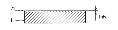
- FIG. 1 shows a cross section of a substrate 11 on which CNTs are formed.
- the substrate 11 is an aluminum metal plate.
- the substrate 11 is made of aluminum or aluminum alloy having a purity exceeding 99%.
- the aluminum alloy can contain at least one or more selected from Si, Zn, Ti, Mn, Cu, Fe, Mg, and Cr as additive metals.
- the substrate 11 has a thickness ThAL.
- the substrate 11 can have any thickness.
- the base material 11 may have a thickness that can be referred to as a foil.
- the base material 11 provides a plane extending in two dimensions.
- the base material 11 is a structure that can maintain the surface shape itself.
- the base material 11 may have a thickness as a structural member that can form a heat transfer product such as a radiator or a heat exchanger.
- FIG. 2 shows the catalyst layer 21 formed on the surface of the substrate 11.
- the catalyst layer 21 is formed of a metal material for synthesizing CNTs.
- the catalyst layer 21 is made of, for example, iron, nickel, cobalt, or the like.
- the catalyst layer 21 is formed so as to cover the entire surface of the substrate 11.
- the catalyst layer 21 has a thickness ThFe.
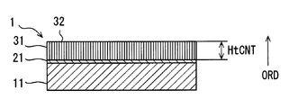
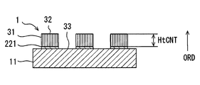
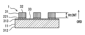
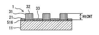
- FIG. 3 shows a cross section of the member 1 with CNT.
- a catalyst layer 21 is disposed on the surface of the substrate 11.
- a CNT alignment film 31 is formed on the catalyst layer 21.
- the CNT alignment film 31 has a large number of CNTs. These many CNTs are oriented toward the orientation direction ORD. In the illustrated example, a large number of CNTs are oriented so that the longitudinal direction of the CNTs extends along a direction perpendicular to the surface of the substrate 11.
- the orientation direction ORD may be inclined with respect to the surface of the substrate 11. Note that the CNTs extend along the alignment direction ORD while meandering slightly.
- the CNT alignment film 31 has a height HtCNT along the alignment direction ORD.
- the CNT alignment film 31 extends over the entire surface of the substrate 11.
- the CNT alignment film 31 protrudes so as to form a convex portion 32 on the substrate 11.
- the height HtCNT roughly corresponds to the length of one CNT.
- One CNT extends in the alignment direction ORD while being bent. Therefore, the length of one CNT is longer than the height HtCNT.
- the height HtCNT is a height at which the high thermal conductivity of the CNT can be effectively used as a heat transfer product such as a radiator or a heat exchanger.
- the CNT alignment film 31 provides a large surface area for the air.
- the CNT provides high thermal conductivity from the substrate 11 along the length direction of the CNT. As a result, the CNT alignment film 31 promotes heat exchange between the air and the substrate 11.
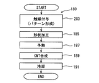
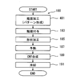
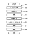
- the manufacturing method 180 of the member 1 with CNT has a plurality of steps for forming the CNT alignment film 31 on the surface of the substrate 11.
- the manufacturing method 180 is performed after arranging the base material 11 in a heating furnace for synthesizing CNTs.
- the order shown is an example and may be changed according to additional requirements.
- the manufacturing method 180 includes a plurality of processes, that is, steps.
- the manufacturing method 180 includes a catalyst application process 183.
- the catalyst layer 21 is formed on the surface of the substrate 11.
- the catalyst layer 21 can be formed by any of various methods such as liquid coating, vapor deposition, sputtering, and addition in a gas phase.
- the manufacturing method 180 can include a shape processing 185.
- the shape processing 185 is prepared as an option.
- the base material 11 is processed into a predetermined shape, for example, a three-dimensional shape.
- mechanical processing such as cutting and bending is applied.
- the manufacturing method 180 includes a preheat treatment 187.
- the preheat treatment 187 preheats the base material 11 and the catalyst layer 21 to a temperature suitable for CNT synthesis.
- the manufacturing method 180 includes a CNT synthesis process 189.
- a CNT raw material is supplied into a heating furnace.
- the raw material is heated and decomposed in a heating furnace.
- CNTs are synthesized on the catalyst that forms the catalyst layer 21.
- CNT grows along the alignment direction ORD.
- the manufacturing method 180 includes a cooling process 191.
- the cooling process 191 cools the CNT-attached member 1 to, for example, room temperature.
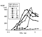
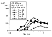
- FIG. 5 is a graph showing the relationship between a plurality of parameters and the CNT height HtCNT ( ⁇ m: micrometer) in the manufacturing method 180.
- the parameters are the volume ratio CO2 / C2H2 (v / v) of the CNT raw material and the thickness ThFe (nm: nanometer) of the catalyst layer 21.
- This graph shows the CNT height HtCNT under the following conditions.
- the catalyst layer 21 is formed on the substrate 11 by sputtering.
- the catalyst layer 21 is formed by depositing iron in the range of 0 nm to 8 nm.
- the base material 11 is made of aluminum having a purity exceeding 99% and is a foil having a thickness of 0.2 mm.
- the shape processing process 185 is not executed.
- the base material 11 and the catalyst layer 21 are heated to 600 ° C. in a mixed gas of argon and hydrogen, and held in an atmosphere at 600 ° C. for 5 minutes.
- a CNT source gas is supplied onto the catalyst layer 21.
- the source gas is a mixture of acetylene (C 2 H 2 ) and carbon dioxide (CO 2 ) in a volume ratio of 1: 0 to 1: 266.
- the atmosphere in the CNT synthesis process that is, the raw material gas is a mixed gas of acetylene, hydrogen, carbon dioxide, and argon. Carbon dioxide is added as a gas for maintaining the activity of the catalyst.
- the CNT synthesis process 189 synthesizes CNTs on the surface of the substrate 11 in an atmosphere in which the volume ratio of acetylene and carbon dioxide as a CNT raw material is 1:10 or more and 1: 300 or less. CNT synthesis can also be referred to as thermal CVD processing.
- the CNT synthesis process 189 is executed for 120 minutes.
- the manufacturing apparatus includes a control device that adjusts the amount of acetylene and the amount of carbon dioxide.
- the growth of the CNT alignment film 31 is promoted in the volume ratio range of 1: 3.3 to 1: 266, or in the volume ratio range of 1:10 to 1: 266.
- the height HtCNT of the CNT alignment film 31 is the highest when the thickness ThFe of the catalyst layer 21 is about 2 nm to 3 nm.
- the CNT alignment film 31 having a height exceeding 400 ⁇ m is obtained at all volume ratios.
- the CNT alignment film 31 having a height exceeding 400 ⁇ m is obtained at a volume ratio of 1: 3.3.
- the volume ratio is 1:10
- the CNT alignment film 31 having a height exceeding 400 ⁇ m is obtained in the catalyst layer 21 having a thickness exceeding 3 nm.
- the highest CNT alignment film 31 is obtained at a volume ratio of 1: 100.
- the CNT alignment film 31 having a height exceeding 500 ⁇ m or 600 ⁇ m is obtained even at a volume ratio of 1: 266.
- the volume ratio is less than 1:10, it was considered that the synthesis of CNT was unstable.
- the high CNT alignment film 31 was synthesized even at a volume ratio of 1: 300. Accordingly, it is considered that the CNT alignment film 31 having a height exceeding 200 ⁇ m, 300 ⁇ m, or 400 ⁇ m, and more desirably 500 ⁇ m can be obtained within the range of the volume ratio of 1:10 or more and 1: 300 or less.
- the volume ratio of acetylene and carbon dioxide in the CNT raw material can be set to 1:10 or more and 1: 300 or less.
- the volume ratio of the CNT raw material may be set to 1:30 or more and 1: 100 or less.
- the thickness ThFe of the catalyst layer 21 can be set around 3 nm when the catalyst is iron.
- the thickness ThFe of the catalyst layer 21 can be set to 2 nm or more.
- the thickness ThFe of the catalyst layer 21 may be set to 3 nm or more. These settings make it possible to stably synthesize the high CNT alignment film 31.
- the thickness ThFe of the catalyst layer 21 can be set to 6 nm or less.
- the thickness ThFe of the catalyst layer 21 may be set to 5 nm or less.
- the thickness ThFe of the catalyst layer 21 may be set to a relatively thick region, for example, 3 nm or more and 5 nm or less.
- the high CNT alignment film 31 is formed on the aluminum base material 11. Specifically, the CNT alignment film 31 having a height of 200 ⁇ m or more or exceeding 200 ⁇ m is obtained. Furthermore, the CNT alignment film 31 having a height of 300 ⁇ m or more is obtained. In a more desirable embodiment, the CNT alignment film 31 having a height of 400 ⁇ m or more is obtained.
- This embodiment is a modified example based on the preceding embodiment.
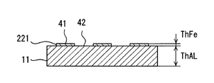
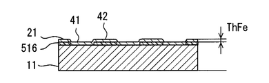
- the CNT alignment film 31 is formed on the entire surface of the substrate 11. Instead, in this embodiment, the CNT alignment film 31 is formed on a part of the surface of the substrate 11.
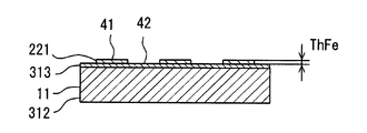
- a partial catalyst layer 221 is formed on the surface of the base material 11 so as to cover only a part of the surface of the base material 11.
- the catalyst layer 221 is formed in the alignment region 41 where the CNT alignment film 31 is intended to be formed.
- the catalyst layer 221 is not formed in the non-formation region 42 where the CNT alignment film 31 is not intended to be formed.
- an alignment region 41 and a non-formation region 42 are formed on the surface of the substrate 11. In the non-formation region 42, the CNT alignment film 31 is not synthesized or does not grow long.
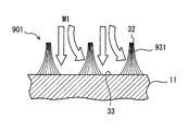
- the member 1 with CNT has a convex part 32 and a concave part 33.
- the convex portion 32 is a bundle of long CNTs formed so as to protrude from the base material 11.
- the convex portion 32 can also be referred to as an island-shaped CNT alignment film 31.
- the concave portion 33 is located between the two convex portions 32. In the concave portion 33, CNT is not synthesized, or the CNT is disorderedly extended from the CNT alignment film 31.
- a catalyst application process 283 is employed.
- the catalyst application treatment 283 is a step of arranging a catalyst.
- the catalyst application process 283 forms a partial catalyst layer 221.
- the catalyst layer 221 can be formed using a stencil mask or photolithography.
- the catalyst application process 283 is also referred to as a pattern formation process for forming the CNT alignment film 31 in a predetermined pattern shape.
- the catalyst application treatment 283 is a step of providing a catalyst in the orientation region 41 where CNTs are formed without providing a catalyst in the non-formation region 42 where CNTs are not formed on the surface of the substrate 11.
- the parameters in the manufacturing process are the same as in the preceding embodiment.
- Subsequent processing 185-191 is the same as the preceding embodiment.
- shape processing 185 for processing the base material 11 into a predetermined shape is executed.
- the long CNT alignment film 31 is formed as in the preceding embodiment. Furthermore, the CNT alignment film 31 can be partially formed on the substrate 11.
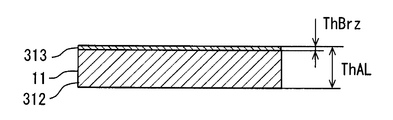
- the base material 11 is a product made from the single material which has aluminum as a main component.
- the substrate 11 has a main layer 312 and a brazing filler metal layer 313.
- the substrate 11 has an aluminum main layer 312 and a brazing filler metal layer 313.
- the brazing material layer 313 is an alloy layer mainly composed of aluminum.
- the brazing material layer 313 has a lower melting point than the main layer 312.
- the brazing filler metal layer 313 has a thickness ThBrz.
- the CNT alignment film 31 is formed on the brazing material layer 313.
- the catalyst layer 221 is formed on the brazing material layer 313.
- the catalyst layer 221 is partially disposed so as to form the alignment region 41 and the non-formation region 42.
- the member 1 with CNT has a CNT alignment film 31 formed on the brazing material layer 313. Also in this embodiment, the CNT alignment film 31 forms the convex portion 32 and the concave portion 33.
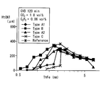
- FIG. 12 and 13 are graphs showing the relationship between the brazing filler metal component and the CNT height HtCNT.
- FIG. 14 shows the components of the brazing filler metal layer as a sample.
- the brazing material named Type A1 is characterized in that it contains aluminum as a main component and 2 to 3.2% of Zn.
- the brazing material named Type B is mainly composed of aluminum, Si is 0.6 to 0.9%, Cu is 0.2 to 0.4%, Mn is 1% to 2%, and Ti is 0.1 to The point which contains 0.2% is characteristic.
- the brazing material named Type A2 is characterized in that it contains less Zn than Type A1.
- the brazing material named Type C is mainly composed of aluminum and contains 9 to 11% of Si. This graph shows the CNT height HtCNT under the following conditions.
- the catalyst layer 21 is formed on the substrate 11 by sputtering.
- the catalyst layer 21 is formed by depositing iron in the range of 0 nm to 7 nm.
- the base material 11 is a foil having a thickness of 0.2 mm.
- the thickness ThBrz of the brazing filler metal layer 313 is about 10% or more of the thickness ThAL.
- the preheat treatment 187 is the same as the preceding embodiment.
- a CNT source gas is supplied onto the catalyst layer 21.
- the source gas is a mixture of acetylene (C 2 H 2 ) and carbon dioxide (CO 2 ) at a volume ratio of 1:30. Carbon dioxide accounts for 1.8 volume percent (vol%). Acetylene accounts for 0.06 volume percent (vol%).
- the volume CNT synthesis process is executed for 120 minutes.
- a reference product (Reference) having no brazing filler metal layer 313 is shown.
- the CNT alignment film 31 having the same height as the reference product is formed.
- the member 1 with CNT which can be utilized for a brazing process is provided.
- the member 1 with CNT is supplied to the brazing process.
- the member 1 with CNT is joined to another member so as to form an article having a predetermined shape in the brazing process.
- This embodiment is a modified example based on the preceding embodiment.
- the shape of the CNT alignment film 31 is controlled by the partial catalyst layer 221.
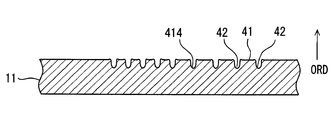
- elements that actively inhibit CNT synthesis and / or oriented growth may be provided on the surface of the substrate 11.
- a rough surface provided on the surface of the base material 11 is used as an inhibiting element.
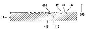
- a rough surface is formed on the surface of the base material 11 by a plurality of grooves 414.
- the groove 414 is an inhibitory element.
- a rough surface is also an obstacle.
- the rough surface corresponds to one groove 414.
- One groove 414 is defined by a U-shaped concave surface.
- the groove 414 is a portion recessed from the original surface (plane) of the substrate 11.
- the U-shaped concave surface provides a surface that intersects the original surface of the substrate 11.
- the U-shaped concave surface is defined by a surface oriented in a direction different from the original surface (plane) of the substrate 11.
- the original surface of the base material 11 is left between the two grooves 414.
- the original surface of the substrate 11 provides an alignment region 41.
- the groove 414 provides a non-oriented region 43. More specifically, the grooves 414 inhibit the oriented growth of CNTs. In the non-alignment region 43, the CNTs are randomly arranged without being aligned along
- rough surface processing 481 is employed.
- the rough surface processing 481 forms a partial rough surface on the surface of the base material 11 by mechanical or chemical surface processing on the base material 11.
- the rough surface forms a rougher surface than other portions on the surface of the substrate 11.
- the rough surface is formed by various surfaces that are inclined with respect to a plane that defines the surface of the substrate 11.
- the rough surface can be formed by scratching the surface of the substrate 11.
- the rough surface may be formed by leaving the surface of the base material 11 before the polishing process.
- the rough surface processing 481 is also referred to as a pattern forming process for forming the CNT alignment film 31 in a predetermined pattern shape.
- the rough surface processing 481 is a process for providing an obstruction element.
- the rough surface processing 481 is a process of providing a rough surface that is more uneven than the surface of the alignment region 41 where the CNTs are formed in the non-alignment region 43 where the CNTs are not formed.
- the rough surface is formed by forming grooves 414 on the surface of the substrate 11.
- the base material 11 is an aluminum plate having a purity exceeding 99%.
- the substrate 11 may be made of an aluminum alloy.
- the groove 414 is formed by a scribe device used in a semiconductor manufacturing process.
- the groove 414 is a groove having a U-shaped cross section with a depth of 20 ⁇ m and a width of 10 ⁇ m.
- the remaining process steps 183-191 are the same as in the previous embodiment.
- a shape processing 185 for processing the base material 11 into a predetermined shape is executed.
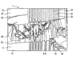
- FIG. 17 is an SEM image of the member 1 with CNT according to an example of this embodiment.
- FIG. 18 is a diagram for explaining each part in the SEM image.
- FIG. 17 and FIG. 18 correspond to perspective views of the fractured surface after a part of the CNT alignment film 31 is peeled off from the CNT-attached member 1 as viewed obliquely from above.
- the upper end surface TP of the CNT alignment film 31 appears in the upper part of the figure.
- the upper end surface TP is formed by the upper ends of many CNTs. Cracks CV generated when a part of the CNT alignment film 31 is peeled off are seen on the upper end surface TP.
- the fracture surface SD of the CNT alignment film 31 appears in the middle of the figure.
- the fracture surface SD is formed by the side surfaces of many CNTs. In the fracture surface SD, a number of vertical lines indicating the CNTs are seen. Further, on the fracture surface SD, random CNT clusters FZ generated when a part of the CNT alignment film 31 is peeled off can be seen. In the lower part of the figure, the surface of the substrate 11 appears. Grooves 414 are seen on the surface of the substrate 11.
- the convex portion 32 formed by the CNT alignment film 31 is located on the alignment region 41.
- a region in which the orientation is randomly disordered is seen on the groove 414. Due to the inclined surface forming the groove 414, the CNT grows in the vertical direction of the slope. Therefore, the CNTs growing from the opposing slopes inhibit the growth, and the growth of the CNT in the vertical direction of the substrate is prevented. The inhibition of the growth is noticeable on the upper end surface TP.
- a narrow recess 33 is formed at a position corresponding to the groove 414.
- the concave portion 33 is formed of CNTs having a reduced density (in other words, voids).
- the CNT alignment film 31 is not formed on the groove 414 due to the rough surface formed by the groove 414. As a result, a recess 33 is formed on the groove 414. It should be noted that the upper end portion of the CNT appears to be slightly inclined and swollen at the corner portion that is the boundary between the convex portion 32 and the concave portion 33.
- a region of the CNT alignment film 31 in which the CNTs are aligned and a region in which the CNTs extend at low density or randomly are formed on the base material 11.
- the shape of the CNT alignment film 31 is defined by the difference in density or alignment state of CNTs, that is, the presence or absence of alignment.
- the plurality of grooves 414 are formed to extend in parallel to each other. Instead, the plurality of grooves 414 may be formed so as to extend in a plurality of directions while intersecting each other. The plurality of grooves 414 may be formed to extend in a random direction in the non-oriented region 43.
- FIG. 19 shows another example of the groove 414.
- the groove 414 has a V-shaped cross section.
- One groove 414 is defined by a pair of inclined surfaces 415 arranged in a V shape. Since the CNT grows perpendicularly to the surface, the slope 415 prevents the CNT from growing in the alignment direction ORD in the groove 414.
- the shape of the groove 414 is not limited to a U-shape or a V-shape.
- the groove 414 can have various shapes such as a semicircular cross section or a rectangular cross section.
- the long CNT alignment film 31 is formed as in the preceding embodiment. Furthermore, the CNT alignment film 31 can be partially formed on the substrate 11.
- the CNT alignment film 31 occupying a long and narrow area is formed.
- a plurality of elongated island-shaped CNT alignment films 31 are formed along the plurality of grooves 414. From another viewpoint, a plurality of linear recesses 33 are formed between the CNT alignment films 31.
- the plurality of island-shaped CNT alignment films 31 increase the heat exchange area with a heat medium such as air on the surface of the substrate 11.
- the elongated island-shaped CNT alignment film 31 is also plate-shaped.
- the plurality of plate-like CNT alignment films 31 have gaps between which a heat medium can be introduced.
- the plurality of plate-like CNT alignment films 31 exhibit a fin-like function when the heat medium flows into the gaps between them.
- the blocking element is provided by the groove 414 and / or the rough surface.
- a material layer that actively inhibits the growth and / or orientation of CNTs may be provided on the surface of the substrate 11.
- an organic material layer containing carbon (C) is used as an inhibiting element.
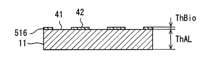
- an organic material layer 516 containing carbon is partially formed on the surface of the substrate 11.
- the organic material layer 516 can be formed using a readily available paint, sign pen, or the like.
- the organic material layer 516 is formed by painting a part of the surface of the substrate 11 with an oil-based sign pen.
- the organic material layer 516 is an inhibitory element.
- the organic material layer 516 is disposed in the non-oriented region 43. In other words, the alignment region 41 and the non-alignment region 43 are formed by the organic material layer 516.
- the catalyst layer 21 is also formed on the organic material layer 516.
- the organic material layer 516 is disposed adjacent to the catalyst layer 21.
- the organic material layer 516 reduces the activity of the catalyst in contact with the organic material layer 516.
- the organic material layer 516 may lose the activity of the catalyst. As a result, CNT does not grow on or be oriented on the organic material layer 516.
- the catalyst layer 21 is formed on the organic material layer 516.
- the organic material layer 516 may be provided on the catalyst layer 21.
- the organic material layer 516 is desirably provided adjacent to the catalyst layer 21. Note that the organic material layer 516 is also referred to as a carbon-containing material layer.
- the member 1 with CNT has a convex portion 32 and a concave portion 33.
- a trace of the organic material layer 516 is left under the recess 33. This trace is a residual layer formed when the organic material layer 516 is altered by a high temperature in the CNT synthesis process. Due to the high temperature in the CNT synthesis process, the organic material layer 516 mixes with the catalyst layer to form a residual layer. Therefore, the residual layer contains the elements constituting the catalyst layer 21 and carbon.
- the residual layer is also called a carbon-containing material layer or a carbon-containing residual layer.
- an organic layer forming process 581 is employed.
- the organic layer forming process 581 is a process of providing an inhibiting element.
- an organic material layer 516 containing carbon is provided in the non-oriented region 43 where CNTs are not formed.
- the organic layer forming process 581 is also referred to as a pattern forming process for forming the CNT alignment film 31 in a predetermined pattern shape.
- the remaining process steps 183-191 are the same as in the previous embodiment.
- a shape processing process 185 for processing the base material 11 into a predetermined shape is executed.
- the organic layer forming process 581 may be performed after the catalyst application process 183, and the catalyst application process 183 may be performed after the shape processing process 185 or the pre-heat treatment 187.
- the long CNT alignment film 31 is formed as in the preceding embodiment. Furthermore, the CNT alignment film 31 can be partially formed on the substrate 11.
- the CNT alignment film 31 can be formed on various shapes of base materials. Further, the CNT alignment film 31 can be formed in various shapes.
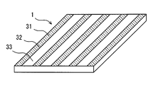
- the member 1 with CNT shown in FIG. 24 has a shape that can be called a plate or a foil.
- the thickness of the member 1 with CNT is set so that its own shape can be maintained.
- the CNT-attached member 1 provides a two-dimensional flat surface.
- the member 1 with CNT is a structure that can maintain the surface shape itself.
- the member 1 with CNT can be called a self-supporting two-dimensional structure.
- the CNT alignment film 31 forms a striped pattern. That is, the CNT alignment film 31 is formed so as to provide the convex portion 32 and the concave portion 33 arranged in a stripe shape.
- the member with CNT 1 illustrated in FIG. 25 has a shape that can be called a pipe.
- the thickness of the member 1 with CNT is set so that its own shape can be maintained.
- the member 1 with CNT provides the curved surface which spreads in three dimensions.
- the member 1 with CNT is a structure that can maintain the surface shape itself.
- the member 1 with CNT can be called a self-supporting three-dimensional structure.
- the CNT alignment film 31 is formed on a surface that spreads smoothly and continuously in three dimensions.
- the CNT alignment film 31 is formed so as to provide a convex portion 32 occupying a part of a three-dimensional surface and a concave portion 33 adjacent thereto.
- the CNT-attached member 1 can adopt various three-dimensional shapes such as blocks and meshes.
- the member 1 with CNT illustrated in FIG. 26 has a three-dimensional shape.
- the thickness of the member 1 with CNT is set so that its own shape can be maintained.
- the member 1 with CNT has a plurality of flat surfaces that spread so as to intersect each other.
- the CNT-attached member 1 is provided with a plurality of planes and a minute curved surface connecting them.
- the member 1 with CNT can be called a self-supporting three-dimensional structure.
- the base material is formed by bending an aluminum plate having a purity of 99% or more into a bracket shape.
- the base material is placed in an electric furnace and heated to 600 ° C. under an argon stream.
- vapor from ferrocene heated to 80 ° C. is included in the argon.
- the substrate is exposed to this atmosphere for 3 minutes.
- a CNT alignment film is synthesized by the same process as in the preceding embodiment.
- an inhibitory element may be provided on the surface of the base material.
- the flat plate may be processed into a three-dimensional shape, and then a CNT alignment film may be synthesized. According to this embodiment, the CNT alignment film is formed on the entire surface of the bracket-shaped substrate.
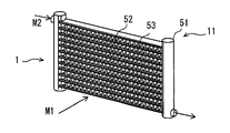
- the member with CNT 1 has a shape of a heat exchanger that provides heat exchange between the two media M1 and M2.
- the member 1 with CNT provides a complicated and various surface.
- the member 1 with CNT includes the base material 11 and the CNT alignment films 31 and 931 formed on the surface of the base material 11.
- a plurality of base materials 11 processed into a shape for forming a heat exchanger are combined to provide the shape of the heat exchanger.
- the base material 11 is aluminum and an aluminum alloy. On the surface of the base material 11, aluminum or aluminum alloy suitable for brazing and brazing is exposed.
- the base material 11 includes a pair of headers 51 and a plurality of tubes 52 that connect between the pair of headers 51. Furthermore, the base material 11 has a plurality of fins 53 for increasing the surface area with respect to the primary medium M1.
- the primary medium M1 flows on the outer surface of the member 1 with CNT.
- the secondary medium M ⁇ b> 2 flows through the pair of headers 51 and the plurality of tubes 52.
- a convex portion 32 and a concave portion 33 are formed by a CNT alignment film 31 on the surface of the member 1 with CNT.
- the primary medium M1 flows in contact with the CNT alignment film 31.
- heat exchange between the primary medium M1 and the CNT alignment film 31 may not be sufficiently obtained.
- FIG. 29 shows the shaped CNT alignment film 931 in this embodiment.
- the shaped CNT alignment film 931 has a trapezoidal shape.
- the shaped CNT alignment film 931 has a base part close to the base material 11 and an end part away from the base material 11. The base is thicker than the end.
- the shaped CNT alignment film 931 is shaped so as to be thicker on the substrate 11 side and become thinner as it is away from the substrate 11.
- the shaped CNT alignment film 931 includes CNTs extending slightly inclined in a bundle of island-like CNTs. However, it can be said that many CNTs included in the bundle of island-like CNTs are still oriented perpendicular to the plane of the surface of the substrate 11.
- the shaped CNT alignment film 931 Even in the shaped CNT alignment film 931, it can be said that the plurality of CNTs are aligned substantially perpendicular to the plane of the surface of the substrate 11.
- the shaped CNT alignment film 931 is easy to introduce the primary medium M1 into the recess 33. As a result, the member 1 with CNT which can exhibit high heat exchange performance as a heat exchanger is manufactured.
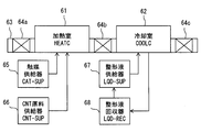
- the manufacturing apparatus of the member 1 with CNT includes a heating chamber (HEATC) 61 and a cooling chamber (COOLC) 62 for performing a cooling process.
- HEATC heating chamber
- COOLC cooling chamber
- the heating chamber 61 has a brazing material at least in part and accommodates a plurality of base materials 11 mainly composed of aluminum.
- the heating chamber melts the brazing material by heating the plurality of base materials 11 and brazes the plurality of base materials 11.
- the heating chamber 61 is a brazing furnace for brazing a plurality of members as a heat exchanger.
- the heating chamber 61 is also a reaction furnace for synthesizing CNTs. CNTs are synthesized simultaneously with brazing or before or after brazing.
- the cooling chamber 62 is a chamber for cooling the member 1 with CNT brazed in the heating chamber 61 and formed with the CNT alignment film 31.
- the cooling chamber 62 is also a shaping chamber for shaping the CNT alignment film 31.
- a preheating chamber for performing preheat treatment may be provided in front of the heating chamber 61.
- the manufacturing apparatus includes a transfer device 63 and gate devices 64a, 64b, and 64c for maintaining the atmosphere in the chambers 61 and 62.
- the gate devices 64a, 64b, 64c can be provided by air curtains or gate valves.
- the manufacturing apparatus includes a catalyst supplier (CAT-SUP) 65 that supplies a catalyst raw material to the heating chamber 61.
- the catalyst supplier 65 supplies the catalyst raw material so that a catalyst for synthesizing CNTs is provided on the surface of the substrate 11. Therefore, the heating chamber 61 is also a furnace for applying a catalyst to the surface of the substrate 11, in other words, a reaction furnace for forming a catalyst layer.
- the catalyst is applied to the substrate 11 simultaneously with brazing, before brazing, or after brazing.
- the catalyst is applied to the substrate 11 before CNT synthesis or simultaneously with CNT synthesis.
- the manufacturing apparatus includes a CNT raw material supplier (CNT-SUP) 66 that supplies the CNT raw material to the heating chamber 61.
- a raw material such as acetylene is supplied into the heating chamber 61 by the CNT raw material supplier 66 to synthesize CNTs.
- the CNT raw material supplier 66 supplies the CNT raw material to the heating chamber 61 so that brazing and synthesis of the CNT alignment film 31 are performed in the heating chamber 61.
- the CNT raw material supplier 66 can include a device for supplying acetylene, a device for supplying carbon dioxide, and a control device for controlling them.
- the control device supplies an appropriate amount of acetylene so that the required CNT is synthesized.
- the control device adjusts the supply amount of acetylene and carbon dioxide so that the volume ratio of acetylene and carbon dioxide is 1:10 or more and 1: 300 or less.
- the manufacturing apparatus has a shaping liquid supplier (LQD-SUP) 67 for supplying the shaping liquid.
- the shaping liquid supplier 67 is configured to supply the shaping liquid to the cooling chamber 62.
- the shaping liquid is, for example, ethanol.
- the shaping liquid is supplied as vapor and may be liquefied in the cooling chamber.
- the manufacturing apparatus has a shaping liquid collector (LQD-REC) 68 for collecting and reusing the shaping liquid.
- the shaping liquid collector 68 is configured to collect the shaping liquid from the cooling chamber 62.
- a pattern forming process 981 and a shaping process 993 are executed.
- the pattern forming process 981 can employ any of the processes disclosed in the preceding embodiments. In this embodiment, a rough surface and / or an organic material layer as an inhibitory element is employed. These methods can partially form the CNT alignment film 31 without depending on the catalyst. Therefore, it can be executed before the shape processing 185.
- the shape processing process 185 is performed before the catalyst application process 183.
- the shape processing 185 is also a process of assembling a plurality of members forming the heat exchanger with a base material including a brazing material layer.
- a pre-heat treatment 187 is performed after the shape processing process 185. Further, after the pre-heat treatment 187, a catalyst application process 183 is performed.
- a catalyst is applied to the preheated base material 11 by supplying a catalyst-containing gas such as ferrocene vapor into the preheated heating chamber 61.
- the catalyst is applied to the surface of the substrate having the shape of a heat exchanger having a plurality of surfaces.
- a process 989 is executed instead of the CNT synthesis process 189 in the preceding embodiment.
- the process 989 is executed after the catalyst application process 183.
- Process 989 is a process in which brazing and CNT synthesis are performed in the common heating chamber 61.
- the shaping process 993 shapes the CNT alignment film 31 into a shape suitable for a heat exchanger.
- the shaping process 993 is also an agglomeration process in which a plurality of CNTs are collected or bundled so as to be thinly contracted at the tip of the bundle of island-like CNTs.
- Liquid can be used to collect multiple CNTs and reduce their spacing.
- the liquid can also be referred to as a shaping liquid.
- An example of the shaping liquid is a volatile liquid.
- the shaping liquid evaporates over time by reducing the shaping liquid vapor concentration in the atmospheric gas, raising the atmospheric temperature, or elapses of time.
- a plurality of CNTs are aggregated and bundled.
- a trapezoid shaped CNT alignment film 931 is obtained.
- the action of the shaping liquid at this time is similar to the action of a hair styling agent for preparing hair.
- An organic solvent can be used as the shaping liquid.
- long CNTs can be formed on the surface of the heat exchanger.
- the CNT alignment film 31 having a predetermined shape can be formed on the surface of the heat exchanger.
- the shape of the CNT alignment film 31 can be shaped into a shape suitable for a heat exchanger.
- FIG. 32 shows another example of the shaped CNT alignment film 931.
- the shape of the CNT alignment film 931 can be adjusted by changing various conditions in the manufacturing method.
- the shape in other words, the fineness of the CNT alignment film 931 can be adjusted by the density of the CNTs in the island-shaped group of CNT alignment films 931, the type of the shaping liquid, the evaporation rate of the shaping liquid, and the like.
- a heat medium such as air is more easily introduced between two adjacent CNT alignment films 931.
- the shaped CNT alignment film 931 increases the direct contact area between the substrate 11 and the heat medium.
- the shaped CNT alignment film 931 provides a fin shape that can be called a microfin.
- a passage shape that can be called a microchannel through which a heat medium can flow is provided.
- the disclosure herein is not limited to the illustrated embodiments.
- the disclosure encompasses the illustrated embodiments and variations by those skilled in the art based thereon.
- the disclosure is not limited to the combinations of parts and / or elements shown in the embodiments.
- the disclosure can be implemented in various combinations.
- the disclosure may have additional parts that can be added to the embodiments.
- the disclosure includes those in which parts and / or elements of the embodiments are omitted.
- the disclosure encompasses the replacement or combination of parts and / or elements between one embodiment and another.
- the technical scope disclosed is not limited to the description of the embodiments. Some technical scope disclosed is shown by the description of the scope of claims, and should be understood to include all modifications within the meaning and scope equivalent to the description of the scope of claims.
- the heat transfer product is exemplified as the use of the member with CNT.
- the member with CNT may be used for various purposes.
- it can be used for a member of an electric device such as a battery and a member for forming a structure.
- the partial CNT alignment film 31, that is, the CNT alignment film 31 formed in a predetermined pattern shape exhibits the effects required for each of various uses.
- the shaped CNT alignment film also exhibits an effect required for each of various uses.
- the base material 11 is made of aluminum or aluminum alloy.
- the base material may be a multilayer material having an aluminum layer or an aluminum alloy layer as a surface layer.
- the groove 414 is formed on the surface of the base material 11 using a scribing device.
- a rough surface or a groove may be formed using various metal processing methods such as cutting, rolling, polishing, and chemical corrosion.
Landscapes
- Chemical & Material Sciences (AREA)
- Engineering & Computer Science (AREA)
- Materials Engineering (AREA)
- Organic Chemistry (AREA)
- Nanotechnology (AREA)
- Chemical Kinetics & Catalysis (AREA)
- Inorganic Chemistry (AREA)
- Physics & Mathematics (AREA)
- Condensed Matter Physics & Semiconductors (AREA)
- General Physics & Mathematics (AREA)
- Crystallography & Structural Chemistry (AREA)
- Thermal Sciences (AREA)
- General Chemical & Material Sciences (AREA)
- Mechanical Engineering (AREA)
- Metallurgy (AREA)
- Manufacturing & Machinery (AREA)
- Composite Materials (AREA)
- Carbon And Carbon Compounds (AREA)
- Catalysts (AREA)
Abstract
La présente invention concerne un élément fixé à des nanotubes de carbone 1, comprenant un substrat à base d'aluminium 11, et un film d'alignement de CNT 31 qui est aligné le long d'une direction d'alignement ORD. Les CNT qui forment le film d'alignement de CNT 31 présentent une longueur de 200 μm ou plus. Les CNT sont synthétisés à partir d'un gaz mixte d'acétylène, d'hydrogène et d'argon. En outre, du dioxyde de carbone est ajouté en vue de maintenir l'activité catalytique. Le rapport de l'acétylène au dioxyde de carbone est ajusté entre 1:10 et 1:300. Le film d'alignement de CNT 31 est formé partiellement. La plage de formation du film d'alignement de CNT 31 est réglée en inhibant la synthèse et/ou la croissance alignée des CNT par une surface rugueuse ou une substance contenant du carbone.
Priority Applications (3)
| Application Number | Priority Date | Filing Date | Title |
|---|---|---|---|
| DE112016006495.0T DE112016006495T5 (de) | 2016-02-26 | 2016-10-21 | Kohlenstoffnanoröhre-Verbundelement, Verfahren zu seiner Herstellung und Vorrichtung zu seiner Herstellung |
| US16/078,809 US20210179431A1 (en) | 2016-02-26 | 2016-10-21 | Carbon nanotube attached member, method for manufacturing the same, and device for manufacturing the same |
| CN201680082654.0A CN108698025B (zh) | 2016-02-26 | 2016-10-21 | 带碳纳米管的部件及其制造方法 |
Applications Claiming Priority (2)
| Application Number | Priority Date | Filing Date | Title |
|---|---|---|---|
| JP2016-035991 | 2016-02-26 | ||
| JP2016035991A JP6515838B2 (ja) | 2016-02-26 | 2016-02-26 | カーボンナノチューブ付部材、その製造方法、およびその製造装置 |
Publications (1)
| Publication Number | Publication Date |
|---|---|
| WO2017145439A1 true WO2017145439A1 (fr) | 2017-08-31 |
Family
ID=59686054
Family Applications (1)
| Application Number | Title | Priority Date | Filing Date |
|---|---|---|---|
| PCT/JP2016/081204 WO2017145439A1 (fr) | 2016-02-26 | 2016-10-21 | Élément fixé à des nanotubes de carbone, son procédé de fabrication, et dispositif de fabrication correspondant |
Country Status (5)
| Country | Link |
|---|---|
| US (1) | US20210179431A1 (fr) |
| JP (1) | JP6515838B2 (fr) |
| CN (1) | CN108698025B (fr) |
| DE (1) | DE112016006495T5 (fr) |
| WO (1) | WO2017145439A1 (fr) |
Families Citing this family (2)
| Publication number | Priority date | Publication date | Assignee | Title |
|---|---|---|---|---|
| CN207235347U (zh) * | 2017-11-22 | 2018-04-13 | 深圳市蓝禾技术有限公司 | 无线充电器 |
| JP7484471B2 (ja) | 2020-06-16 | 2024-05-16 | 富士通株式会社 | カーボンナノチューブシート、電子機器及びカーボンナノチューブシートの製造方法 |
Citations (6)
| Publication number | Priority date | Publication date | Assignee | Title |
|---|---|---|---|---|
| JP2005075711A (ja) * | 2003-09-03 | 2005-03-24 | Toyota Motor Corp | カーボンナノチューブの配向方法及び配向したカーボンナノチューブ |
| JP2006306704A (ja) * | 2005-03-30 | 2006-11-09 | Sonac Kk | 炭素膜の製造方法および炭素膜 |
| JP2008303117A (ja) * | 2007-06-08 | 2008-12-18 | Denso Corp | カーボンナノチューブ製造装置及びカーボンナノチューブの製造方法 |
| JP2010031193A (ja) * | 2008-07-31 | 2010-02-12 | Denso Corp | 接着用シート、及びその製造方法 |
| JP2011057466A (ja) * | 2009-09-07 | 2011-03-24 | Fujitsu Ltd | カーボンナノチューブシート構造体およびその製造方法、半導体装置 |
| JP2015078120A (ja) * | 2008-12-30 | 2015-04-23 | 独立行政法人産業技術総合研究所 | 単層カーボンナノチューブ配向集合体、バルク状単層カーボンナノチューブ配向集合体、粉体状単層カーボンナノチューブ配向集合体 |
Family Cites Families (11)
| Publication number | Priority date | Publication date | Assignee | Title |
|---|---|---|---|---|
| US20040009353A1 (en) * | 1999-06-14 | 2004-01-15 | Knowles Timothy R. | PCM/aligned fiber composite thermal interface |
| AUPQ304199A0 (en) * | 1999-09-23 | 1999-10-21 | Commonwealth Scientific And Industrial Research Organisation | Patterned carbon nanotubes |
| TWI276138B (en) * | 2004-09-24 | 2007-03-11 | Ind Tech Res Inst | Array-like flat lighting source |
| US20070116631A1 (en) * | 2004-10-18 | 2007-05-24 | The Regents Of The University Of California | Arrays of long carbon nanotubes for fiber spinning |
| JP4817296B2 (ja) * | 2006-01-06 | 2011-11-16 | 独立行政法人産業技術総合研究所 | 配向カーボンナノチューブ・バルク集合体ならびにその製造方法および用途 |
| US7868531B2 (en) * | 2006-05-05 | 2011-01-11 | Brother International Corporation | Carbon nanotube arrays for field electron emission |
| US9318295B2 (en) * | 2008-01-18 | 2016-04-19 | The United States Of America As Represented By The Administrator Of The Nasa | Carbon nanotube patterning on a metal substrate |
| JP2009208975A (ja) * | 2008-02-29 | 2009-09-17 | National Institute Of Advanced Industrial & Technology | カーボンナノチューブ構造体及びその製造方法 |
| US20140154416A1 (en) * | 2011-05-31 | 2014-06-05 | National Institute Of Advanced Industrial Science And Technology | Apparatus and method for producing oriented carbon nanotube aggregate |
| US9028791B1 (en) * | 2012-11-27 | 2015-05-12 | Dream Matter, LLC | System and method for manufacturing carbon nanotubes |
| CN103833001B (zh) * | 2014-01-03 | 2015-08-12 | 南京康众光电科技有限公司 | 一种船槽式图案结构生长的碳纳米管生长方法及其发射体 |
-
2016
- 2016-02-26 JP JP2016035991A patent/JP6515838B2/ja active Active
- 2016-10-21 WO PCT/JP2016/081204 patent/WO2017145439A1/fr active Application Filing
- 2016-10-21 DE DE112016006495.0T patent/DE112016006495T5/de not_active Ceased
- 2016-10-21 US US16/078,809 patent/US20210179431A1/en not_active Abandoned
- 2016-10-21 CN CN201680082654.0A patent/CN108698025B/zh active Active
Patent Citations (6)
| Publication number | Priority date | Publication date | Assignee | Title |
|---|---|---|---|---|
| JP2005075711A (ja) * | 2003-09-03 | 2005-03-24 | Toyota Motor Corp | カーボンナノチューブの配向方法及び配向したカーボンナノチューブ |
| JP2006306704A (ja) * | 2005-03-30 | 2006-11-09 | Sonac Kk | 炭素膜の製造方法および炭素膜 |
| JP2008303117A (ja) * | 2007-06-08 | 2008-12-18 | Denso Corp | カーボンナノチューブ製造装置及びカーボンナノチューブの製造方法 |
| JP2010031193A (ja) * | 2008-07-31 | 2010-02-12 | Denso Corp | 接着用シート、及びその製造方法 |
| JP2015078120A (ja) * | 2008-12-30 | 2015-04-23 | 独立行政法人産業技術総合研究所 | 単層カーボンナノチューブ配向集合体、バルク状単層カーボンナノチューブ配向集合体、粉体状単層カーボンナノチューブ配向集合体 |
| JP2011057466A (ja) * | 2009-09-07 | 2011-03-24 | Fujitsu Ltd | カーボンナノチューブシート構造体およびその製造方法、半導体装置 |
Also Published As
| Publication number | Publication date |
|---|---|
| CN108698025B (zh) | 2021-08-17 |
| JP2017149627A (ja) | 2017-08-31 |
| CN108698025A (zh) | 2018-10-23 |
| JP6515838B2 (ja) | 2019-05-22 |
| DE112016006495T5 (de) | 2018-11-15 |
| US20210179431A1 (en) | 2021-06-17 |
Similar Documents
| Publication | Publication Date | Title |
|---|---|---|
| ES2346535T3 (es) | Aplicacion de pulverizacion termica de material de soldadura fuerte para la fabricacion de dispositivos de transferencia de calor. | |
| JP4508894B2 (ja) | 炭素ナノチューブのマトリックス構造及びその製造方法 | |
| WO2017145439A1 (fr) | Élément fixé à des nanotubes de carbone, son procédé de fabrication, et dispositif de fabrication correspondant | |
| US20150368535A1 (en) | Graphene composites and methods of fabrication | |
| MX2012005640A (es) | Procesamiento para la aplicacion de mezclas de carbono/estaño a capas de metal o aleaciones. | |
| NL2026635B1 (en) | Integrated manufacturing of core-shell particles for Li-ion batteries | |
| JP7065779B2 (ja) | 金属ナノ粒子を用いた付加製造プロセス | |
| KR20110055653A (ko) | 탄소 나노튜브, 풀러렌 및/또는 그래핀을 함유하는 코팅을 생성하기 위한 방법 | |
| JP2008120658A (ja) | 多層カーボンナノチューブの集合構造 | |
| WO2017156297A3 (fr) | Matériaux de graphène hybrides et procédés de fabrication | |
| CN105679723B (zh) | 一种热界面材料及其制备方法、导热片和散热系统 | |
| US20110186267A1 (en) | Heat transfer device with anisotropic thermal conducting micro structures | |
| JP2008045202A (ja) | 気相反応法を用いた金属ナノ粉末の製造方法 | |
| Munoz et al. | Synthesis of SiC nanorods from sheets of single-walled carbon nanotubes | |
| JP2007070137A (ja) | カーボンナノチューブの生成方法およびそれに用いる三層構造体 | |
| JP2008201648A (ja) | カーボンナノチューブの製造装置およびカーボンナノチューブの製造方法 | |
| JP7272855B2 (ja) | 多層カーボンナノチューブ、多層カーボンナノチューブ集合体および多層カーボンナノチューブの製造方法 | |
| Zhang et al. | Wetting of AgCuTi alloys on quartz fiber reinforced composite modified by vertically aligned carbon nanotubes | |
| KR101313753B1 (ko) | 탄소나노플레이크의 성장 방법 및 이에 의해 형성된 탄소나노플레이크 구조물 | |
| US6855659B1 (en) | Manufacturing method of carbon nanotubes and laser irradiation target for the manufacture thereof | |
| Benavente et al. | Melamine-assisted synthesis of nitrogen-doped ReS2 nanosheets/carbon composites | |
| JP2017149627A5 (fr) | ||
| JP5598946B2 (ja) | ろう材層付きアルミニウム部材の製造方法及び熱交換器の製造方法 | |
| Pan | Carbon Nanomaterials and 2D Layered Materials Development with Chemical Vapor Deposition | |
| Mäklin et al. | Solder transfer of carbon nanotube microfin coolers to ceramic chips |
Legal Events
| Date | Code | Title | Description |
|---|---|---|---|
| 122 | Ep: pct application non-entry in european phase |
Ref document number: 16891595 Country of ref document: EP Kind code of ref document: A1 |