WO2017145439A1 - カーボンナノチューブ付部材、その製造方法、およびその製造装置 - Google Patents
カーボンナノチューブ付部材、その製造方法、およびその製造装置 Download PDFInfo
- Publication number
- WO2017145439A1 WO2017145439A1 PCT/JP2016/081204 JP2016081204W WO2017145439A1 WO 2017145439 A1 WO2017145439 A1 WO 2017145439A1 JP 2016081204 W JP2016081204 W JP 2016081204W WO 2017145439 A1 WO2017145439 A1 WO 2017145439A1
- Authority
- WO
- WIPO (PCT)
- Prior art keywords
- cnt
- alignment film
- base material
- carbon
- carbon nanotubes
- Prior art date
Links
Images


Classifications
-
- C—CHEMISTRY; METALLURGY
- C01—INORGANIC CHEMISTRY
- C01B—NON-METALLIC ELEMENTS; COMPOUNDS THEREOF; METALLOIDS OR COMPOUNDS THEREOF NOT COVERED BY SUBCLASS C01C
- C01B32/00—Carbon; Compounds thereof
- C01B32/15—Nano-sized carbon materials
- C01B32/158—Carbon nanotubes
- C01B32/16—Preparation
- C01B32/162—Preparation characterised by catalysts
-
- B—PERFORMING OPERATIONS; TRANSPORTING
- B01—PHYSICAL OR CHEMICAL PROCESSES OR APPARATUS IN GENERAL
- B01J—CHEMICAL OR PHYSICAL PROCESSES, e.g. CATALYSIS OR COLLOID CHEMISTRY; THEIR RELEVANT APPARATUS
- B01J15/00—Chemical processes in general for reacting gaseous media with non-particulate solids, e.g. sheet material; Apparatus specially adapted therefor
- B01J15/005—Chemical processes in general for reacting gaseous media with non-particulate solids, e.g. sheet material; Apparatus specially adapted therefor in the presence of catalytically active bodies, e.g. porous plates
-
- B—PERFORMING OPERATIONS; TRANSPORTING
- B01—PHYSICAL OR CHEMICAL PROCESSES OR APPARATUS IN GENERAL
- B01J—CHEMICAL OR PHYSICAL PROCESSES, e.g. CATALYSIS OR COLLOID CHEMISTRY; THEIR RELEVANT APPARATUS
- B01J21/00—Catalysts comprising the elements, oxides, or hydroxides of magnesium, boron, aluminium, carbon, silicon, titanium, zirconium, or hafnium
- B01J21/02—Boron or aluminium; Oxides or hydroxides thereof
- B01J21/04—Alumina
-
- B—PERFORMING OPERATIONS; TRANSPORTING
- B01—PHYSICAL OR CHEMICAL PROCESSES OR APPARATUS IN GENERAL
- B01J—CHEMICAL OR PHYSICAL PROCESSES, e.g. CATALYSIS OR COLLOID CHEMISTRY; THEIR RELEVANT APPARATUS
- B01J23/00—Catalysts comprising metals or metal oxides or hydroxides, not provided for in group B01J21/00
- B01J23/70—Catalysts comprising metals or metal oxides or hydroxides, not provided for in group B01J21/00 of the iron group metals or copper
- B01J23/74—Iron group metals
- B01J23/745—Iron
-
- B—PERFORMING OPERATIONS; TRANSPORTING
- B01—PHYSICAL OR CHEMICAL PROCESSES OR APPARATUS IN GENERAL
- B01J—CHEMICAL OR PHYSICAL PROCESSES, e.g. CATALYSIS OR COLLOID CHEMISTRY; THEIR RELEVANT APPARATUS
- B01J37/00—Processes, in general, for preparing catalysts; Processes, in general, for activation of catalysts
- B01J37/02—Impregnation, coating or precipitation
- B01J37/0215—Coating
- B01J37/0225—Coating of metal substrates
-
- B—PERFORMING OPERATIONS; TRANSPORTING
- B01—PHYSICAL OR CHEMICAL PROCESSES OR APPARATUS IN GENERAL
- B01J—CHEMICAL OR PHYSICAL PROCESSES, e.g. CATALYSIS OR COLLOID CHEMISTRY; THEIR RELEVANT APPARATUS
- B01J37/00—Processes, in general, for preparing catalysts; Processes, in general, for activation of catalysts
- B01J37/08—Heat treatment
-
- B—PERFORMING OPERATIONS; TRANSPORTING
- B82—NANOTECHNOLOGY
- B82Y—SPECIFIC USES OR APPLICATIONS OF NANOSTRUCTURES; MEASUREMENT OR ANALYSIS OF NANOSTRUCTURES; MANUFACTURE OR TREATMENT OF NANOSTRUCTURES
- B82Y30/00—Nanotechnology for materials or surface science, e.g. nanocomposites
-
- B—PERFORMING OPERATIONS; TRANSPORTING
- B82—NANOTECHNOLOGY
- B82Y—SPECIFIC USES OR APPLICATIONS OF NANOSTRUCTURES; MEASUREMENT OR ANALYSIS OF NANOSTRUCTURES; MANUFACTURE OR TREATMENT OF NANOSTRUCTURES
- B82Y40/00—Manufacture or treatment of nanostructures
-
- C—CHEMISTRY; METALLURGY
- C01—INORGANIC CHEMISTRY
- C01B—NON-METALLIC ELEMENTS; COMPOUNDS THEREOF; METALLOIDS OR COMPOUNDS THEREOF NOT COVERED BY SUBCLASS C01C
- C01B32/00—Carbon; Compounds thereof
- C01B32/15—Nano-sized carbon materials
- C01B32/158—Carbon nanotubes
-
- C—CHEMISTRY; METALLURGY
- C01—INORGANIC CHEMISTRY
- C01B—NON-METALLIC ELEMENTS; COMPOUNDS THEREOF; METALLOIDS OR COMPOUNDS THEREOF NOT COVERED BY SUBCLASS C01C
- C01B32/00—Carbon; Compounds thereof
- C01B32/15—Nano-sized carbon materials
- C01B32/158—Carbon nanotubes
- C01B32/16—Preparation
-
- C—CHEMISTRY; METALLURGY
- C01—INORGANIC CHEMISTRY
- C01B—NON-METALLIC ELEMENTS; COMPOUNDS THEREOF; METALLOIDS OR COMPOUNDS THEREOF NOT COVERED BY SUBCLASS C01C
- C01B32/00—Carbon; Compounds thereof
- C01B32/15—Nano-sized carbon materials
- C01B32/158—Carbon nanotubes
- C01B32/168—After-treatment
-
- C—CHEMISTRY; METALLURGY
- C23—COATING METALLIC MATERIAL; COATING MATERIAL WITH METALLIC MATERIAL; CHEMICAL SURFACE TREATMENT; DIFFUSION TREATMENT OF METALLIC MATERIAL; COATING BY VACUUM EVAPORATION, BY SPUTTERING, BY ION IMPLANTATION OR BY CHEMICAL VAPOUR DEPOSITION, IN GENERAL; INHIBITING CORROSION OF METALLIC MATERIAL OR INCRUSTATION IN GENERAL
- C23C—COATING METALLIC MATERIAL; COATING MATERIAL WITH METALLIC MATERIAL; SURFACE TREATMENT OF METALLIC MATERIAL BY DIFFUSION INTO THE SURFACE, BY CHEMICAL CONVERSION OR SUBSTITUTION; COATING BY VACUUM EVAPORATION, BY SPUTTERING, BY ION IMPLANTATION OR BY CHEMICAL VAPOUR DEPOSITION, IN GENERAL
- C23C16/00—Chemical coating by decomposition of gaseous compounds, without leaving reaction products of surface material in the coating, i.e. chemical vapour deposition [CVD] processes
- C23C16/22—Chemical coating by decomposition of gaseous compounds, without leaving reaction products of surface material in the coating, i.e. chemical vapour deposition [CVD] processes characterised by the deposition of inorganic material, other than metallic material
- C23C16/26—Deposition of carbon only
-
- C—CHEMISTRY; METALLURGY
- C01—INORGANIC CHEMISTRY
- C01B—NON-METALLIC ELEMENTS; COMPOUNDS THEREOF; METALLOIDS OR COMPOUNDS THEREOF NOT COVERED BY SUBCLASS C01C
- C01B2202/00—Structure or properties of carbon nanotubes
- C01B2202/08—Aligned nanotubes
-
- C—CHEMISTRY; METALLURGY
- C01—INORGANIC CHEMISTRY
- C01B—NON-METALLIC ELEMENTS; COMPOUNDS THEREOF; METALLOIDS OR COMPOUNDS THEREOF NOT COVERED BY SUBCLASS C01C
- C01B2202/00—Structure or properties of carbon nanotubes
- C01B2202/20—Nanotubes characterized by their properties
- C01B2202/24—Thermal properties
-
- C—CHEMISTRY; METALLURGY
- C01—INORGANIC CHEMISTRY
- C01B—NON-METALLIC ELEMENTS; COMPOUNDS THEREOF; METALLOIDS OR COMPOUNDS THEREOF NOT COVERED BY SUBCLASS C01C
- C01B2202/00—Structure or properties of carbon nanotubes
- C01B2202/20—Nanotubes characterized by their properties
- C01B2202/34—Length
-
- C—CHEMISTRY; METALLURGY
- C01—INORGANIC CHEMISTRY
- C01B—NON-METALLIC ELEMENTS; COMPOUNDS THEREOF; METALLOIDS OR COMPOUNDS THEREOF NOT COVERED BY SUBCLASS C01C
- C01B2202/00—Structure or properties of carbon nanotubes
- C01B2202/20—Nanotubes characterized by their properties
- C01B2202/36—Diameter
-
- C—CHEMISTRY; METALLURGY
- C01—INORGANIC CHEMISTRY
- C01P—INDEXING SCHEME RELATING TO STRUCTURAL AND PHYSICAL ASPECTS OF SOLID INORGANIC COMPOUNDS
- C01P2004/00—Particle morphology
- C01P2004/01—Particle morphology depicted by an image
- C01P2004/03—Particle morphology depicted by an image obtained by SEM
Definitions
- the disclosure in this specification relates to a carbon nanotube-attached member, a manufacturing method thereof, and a manufacturing apparatus thereof.
- CNT carbon nanotubes
- a method for synthesizing carbon nanotubes that is, a production method, after forming a metal as a catalyst on a substrate and placing it in a heated furnace, a gas containing carbon such as acetylene or ethanol as a raw material is used as a furnace.
- a method of supplying the inside In order to decompose the gas and maintain the catalytic activity, the temperature in the furnace is usually maintained at about 700 ° C. to 800 ° C.
- Patent Document 1 discloses a technique for forming a CNT alignment film in a predetermined range on a substrate. Patent Document 1 makes it possible to form a patterned CNT alignment film by forming a catalyst necessary for CNT synthesis within a required range, that is, by patterning.
- Patent Document 2 proposes a method of synthesizing CNT at a relatively low temperature.
- tip discharge plasma CVD is used in addition to normal thermal decomposition. Thereby, H2 gas and CH4 are activated, and the CNT alignment film is synthesized.
- Patent Document 3 proposes a method of synthesizing CNTs on aluminum or magnesium.
- Patent Document 1 requires a means for forming a patterned catalyst at a required place. For example, since a stencil mask or photolithography is required, the manufacturing process becomes complicated. Moreover, the method of patent document 1 is restricted to the application to a flat board
- One object disclosed is to provide a member with carbon nanotubes in which long CNTs are oriented, a method for producing the member, and a device for producing the member.
- Another object of the disclosure is to provide a carbon nanotube-attached member in which a CNT alignment film is partially formed, a manufacturing method thereof, and a manufacturing apparatus thereof.
- Yet another object disclosed is to provide a carbon nanotube-attached member in which a CNT alignment film formed of long CNTs is formed on the surface of a base material mainly composed of aluminum, a manufacturing method thereof, and a manufacturing apparatus thereof. Is to provide.
- Still another object of the present invention is to provide a carbon nanotube-attached member on which a CNT alignment film capable of brazing a base material mainly composed of aluminum and synthesizing CNTs by a simple apparatus, and a method for producing the same And an apparatus for manufacturing the same.
- the carbon nanotube-attached member disclosed herein has a base material (11) containing aluminum as a main component and a plurality of carbon nanotubes having a length of 200 ⁇ m or more oriented along a predetermined orientation direction. And a CNT alignment film (31, 931) disposed on the surface.
- a CNT alignment film in which a plurality of carbon nanotubes having a length of 200 ⁇ m or more are aligned can be provided on a base material mainly composed of aluminum.
- the method for producing a member with carbon nanotubes disclosed herein includes a step (183, 283) of disposing a catalyst (21, 221) for synthesizing carbon nanotubes on the surface of a base material mainly composed of aluminum, and a catalyst.
- the activity of the catalyst is maintained by carbon dioxide even at a low temperature. Therefore, the carbon nanotube can be synthesized at a low temperature. As a result, the CNT alignment film can be formed on the surface of the base material mainly composed of aluminum.
- the apparatus for producing a member with carbon nanotubes disclosed herein has a brazing material (313) at least in part, accommodates a base material (11) mainly composed of aluminum, and heats the base material.
- a raw material supplier (66) for supplying the carbon nanotube raw material to the heating chamber is provided so that the synthesis on the surface of the material is performed in the heating chamber.
- brazing and carbon nanotube synthesis can be performed in a common heating chamber.
- FIG. 18 is a diagram for explaining the SEM image illustrated in FIG. 17. It is sectional drawing which shows the modification of 4th Embodiment. It is sectional drawing in the intermediate
- a carbon nanotube-attached member (CNT-attached member) and a manufacturing method thereof are disclosed.
- the carbon nanotube alignment film (CNT alignment film) is a film in which a large number of carbon nanotubes (CNT) are aligned.
- the CNT alignment film is disposed on the surface of a metal substrate. In one example, the CNTs are oriented to extend perpendicular to the plane provided by the surface of the substrate.
- the member with CNT is also called a member coated with CNT, a CNT composite material, or a CNT structure. 1, 2 and 3 show the shape of the material at each stage of the manufacturing process of the member with CNT.
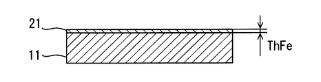
- FIG. 1 shows a cross section of a substrate 11 on which CNTs are formed.
- the substrate 11 is an aluminum metal plate.
- the substrate 11 is made of aluminum or aluminum alloy having a purity exceeding 99%.
- the aluminum alloy can contain at least one or more selected from Si, Zn, Ti, Mn, Cu, Fe, Mg, and Cr as additive metals.
- the substrate 11 has a thickness ThAL.
- the substrate 11 can have any thickness.
- the base material 11 may have a thickness that can be referred to as a foil.
- the base material 11 provides a plane extending in two dimensions.
- the base material 11 is a structure that can maintain the surface shape itself.
- the base material 11 may have a thickness as a structural member that can form a heat transfer product such as a radiator or a heat exchanger.
- FIG. 2 shows the catalyst layer 21 formed on the surface of the substrate 11.
- the catalyst layer 21 is formed of a metal material for synthesizing CNTs.
- the catalyst layer 21 is made of, for example, iron, nickel, cobalt, or the like.
- the catalyst layer 21 is formed so as to cover the entire surface of the substrate 11.
- the catalyst layer 21 has a thickness ThFe.
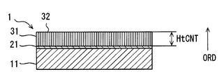
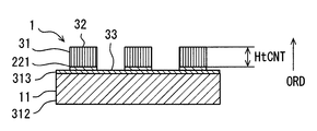
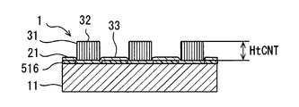
- FIG. 3 shows a cross section of the member 1 with CNT.
- a catalyst layer 21 is disposed on the surface of the substrate 11.
- a CNT alignment film 31 is formed on the catalyst layer 21.
- the CNT alignment film 31 has a large number of CNTs. These many CNTs are oriented toward the orientation direction ORD. In the illustrated example, a large number of CNTs are oriented so that the longitudinal direction of the CNTs extends along a direction perpendicular to the surface of the substrate 11.
- the orientation direction ORD may be inclined with respect to the surface of the substrate 11. Note that the CNTs extend along the alignment direction ORD while meandering slightly.
- the CNT alignment film 31 has a height HtCNT along the alignment direction ORD.
- the CNT alignment film 31 extends over the entire surface of the substrate 11.
- the CNT alignment film 31 protrudes so as to form a convex portion 32 on the substrate 11.
- the height HtCNT roughly corresponds to the length of one CNT.
- One CNT extends in the alignment direction ORD while being bent. Therefore, the length of one CNT is longer than the height HtCNT.
- the height HtCNT is a height at which the high thermal conductivity of the CNT can be effectively used as a heat transfer product such as a radiator or a heat exchanger.
- the CNT alignment film 31 provides a large surface area for the air.
- the CNT provides high thermal conductivity from the substrate 11 along the length direction of the CNT. As a result, the CNT alignment film 31 promotes heat exchange between the air and the substrate 11.
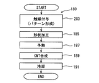
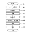
- the manufacturing method 180 of the member 1 with CNT has a plurality of steps for forming the CNT alignment film 31 on the surface of the substrate 11.
- the manufacturing method 180 is performed after arranging the base material 11 in a heating furnace for synthesizing CNTs.
- the order shown is an example and may be changed according to additional requirements.
- the manufacturing method 180 includes a plurality of processes, that is, steps.
- the manufacturing method 180 includes a catalyst application process 183.
- the catalyst layer 21 is formed on the surface of the substrate 11.
- the catalyst layer 21 can be formed by any of various methods such as liquid coating, vapor deposition, sputtering, and addition in a gas phase.
- the manufacturing method 180 can include a shape processing 185.
- the shape processing 185 is prepared as an option.
- the base material 11 is processed into a predetermined shape, for example, a three-dimensional shape.
- mechanical processing such as cutting and bending is applied.
- the manufacturing method 180 includes a preheat treatment 187.
- the preheat treatment 187 preheats the base material 11 and the catalyst layer 21 to a temperature suitable for CNT synthesis.
- the manufacturing method 180 includes a CNT synthesis process 189.
- a CNT raw material is supplied into a heating furnace.
- the raw material is heated and decomposed in a heating furnace.
- CNTs are synthesized on the catalyst that forms the catalyst layer 21.
- CNT grows along the alignment direction ORD.
- the manufacturing method 180 includes a cooling process 191.
- the cooling process 191 cools the CNT-attached member 1 to, for example, room temperature.
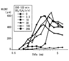
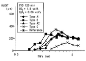
- FIG. 5 is a graph showing the relationship between a plurality of parameters and the CNT height HtCNT ( ⁇ m: micrometer) in the manufacturing method 180.
- the parameters are the volume ratio CO2 / C2H2 (v / v) of the CNT raw material and the thickness ThFe (nm: nanometer) of the catalyst layer 21.
- This graph shows the CNT height HtCNT under the following conditions.
- the catalyst layer 21 is formed on the substrate 11 by sputtering.
- the catalyst layer 21 is formed by depositing iron in the range of 0 nm to 8 nm.
- the base material 11 is made of aluminum having a purity exceeding 99% and is a foil having a thickness of 0.2 mm.
- the shape processing process 185 is not executed.
- the base material 11 and the catalyst layer 21 are heated to 600 ° C. in a mixed gas of argon and hydrogen, and held in an atmosphere at 600 ° C. for 5 minutes.
- a CNT source gas is supplied onto the catalyst layer 21.
- the source gas is a mixture of acetylene (C 2 H 2 ) and carbon dioxide (CO 2 ) in a volume ratio of 1: 0 to 1: 266.
- the atmosphere in the CNT synthesis process that is, the raw material gas is a mixed gas of acetylene, hydrogen, carbon dioxide, and argon. Carbon dioxide is added as a gas for maintaining the activity of the catalyst.
- the CNT synthesis process 189 synthesizes CNTs on the surface of the substrate 11 in an atmosphere in which the volume ratio of acetylene and carbon dioxide as a CNT raw material is 1:10 or more and 1: 300 or less. CNT synthesis can also be referred to as thermal CVD processing.
- the CNT synthesis process 189 is executed for 120 minutes.
- the manufacturing apparatus includes a control device that adjusts the amount of acetylene and the amount of carbon dioxide.
- the growth of the CNT alignment film 31 is promoted in the volume ratio range of 1: 3.3 to 1: 266, or in the volume ratio range of 1:10 to 1: 266.
- the height HtCNT of the CNT alignment film 31 is the highest when the thickness ThFe of the catalyst layer 21 is about 2 nm to 3 nm.
- the CNT alignment film 31 having a height exceeding 400 ⁇ m is obtained at all volume ratios.
- the CNT alignment film 31 having a height exceeding 400 ⁇ m is obtained at a volume ratio of 1: 3.3.
- the volume ratio is 1:10
- the CNT alignment film 31 having a height exceeding 400 ⁇ m is obtained in the catalyst layer 21 having a thickness exceeding 3 nm.
- the highest CNT alignment film 31 is obtained at a volume ratio of 1: 100.
- the CNT alignment film 31 having a height exceeding 500 ⁇ m or 600 ⁇ m is obtained even at a volume ratio of 1: 266.
- the volume ratio is less than 1:10, it was considered that the synthesis of CNT was unstable.
- the high CNT alignment film 31 was synthesized even at a volume ratio of 1: 300. Accordingly, it is considered that the CNT alignment film 31 having a height exceeding 200 ⁇ m, 300 ⁇ m, or 400 ⁇ m, and more desirably 500 ⁇ m can be obtained within the range of the volume ratio of 1:10 or more and 1: 300 or less.
- the volume ratio of acetylene and carbon dioxide in the CNT raw material can be set to 1:10 or more and 1: 300 or less.
- the volume ratio of the CNT raw material may be set to 1:30 or more and 1: 100 or less.
- the thickness ThFe of the catalyst layer 21 can be set around 3 nm when the catalyst is iron.
- the thickness ThFe of the catalyst layer 21 can be set to 2 nm or more.
- the thickness ThFe of the catalyst layer 21 may be set to 3 nm or more. These settings make it possible to stably synthesize the high CNT alignment film 31.
- the thickness ThFe of the catalyst layer 21 can be set to 6 nm or less.
- the thickness ThFe of the catalyst layer 21 may be set to 5 nm or less.
- the thickness ThFe of the catalyst layer 21 may be set to a relatively thick region, for example, 3 nm or more and 5 nm or less.
- the high CNT alignment film 31 is formed on the aluminum base material 11. Specifically, the CNT alignment film 31 having a height of 200 ⁇ m or more or exceeding 200 ⁇ m is obtained. Furthermore, the CNT alignment film 31 having a height of 300 ⁇ m or more is obtained. In a more desirable embodiment, the CNT alignment film 31 having a height of 400 ⁇ m or more is obtained.
- This embodiment is a modified example based on the preceding embodiment.
- the CNT alignment film 31 is formed on the entire surface of the substrate 11. Instead, in this embodiment, the CNT alignment film 31 is formed on a part of the surface of the substrate 11.
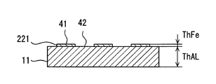
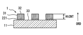
- a partial catalyst layer 221 is formed on the surface of the base material 11 so as to cover only a part of the surface of the base material 11.
- the catalyst layer 221 is formed in the alignment region 41 where the CNT alignment film 31 is intended to be formed.
- the catalyst layer 221 is not formed in the non-formation region 42 where the CNT alignment film 31 is not intended to be formed.
- an alignment region 41 and a non-formation region 42 are formed on the surface of the substrate 11. In the non-formation region 42, the CNT alignment film 31 is not synthesized or does not grow long.
- the member 1 with CNT has a convex part 32 and a concave part 33.
- the convex portion 32 is a bundle of long CNTs formed so as to protrude from the base material 11.
- the convex portion 32 can also be referred to as an island-shaped CNT alignment film 31.
- the concave portion 33 is located between the two convex portions 32. In the concave portion 33, CNT is not synthesized, or the CNT is disorderedly extended from the CNT alignment film 31.
- a catalyst application process 283 is employed.
- the catalyst application treatment 283 is a step of arranging a catalyst.
- the catalyst application process 283 forms a partial catalyst layer 221.
- the catalyst layer 221 can be formed using a stencil mask or photolithography.
- the catalyst application process 283 is also referred to as a pattern formation process for forming the CNT alignment film 31 in a predetermined pattern shape.
- the catalyst application treatment 283 is a step of providing a catalyst in the orientation region 41 where CNTs are formed without providing a catalyst in the non-formation region 42 where CNTs are not formed on the surface of the substrate 11.
- the parameters in the manufacturing process are the same as in the preceding embodiment.
- Subsequent processing 185-191 is the same as the preceding embodiment.
- shape processing 185 for processing the base material 11 into a predetermined shape is executed.
- the long CNT alignment film 31 is formed as in the preceding embodiment. Furthermore, the CNT alignment film 31 can be partially formed on the substrate 11.
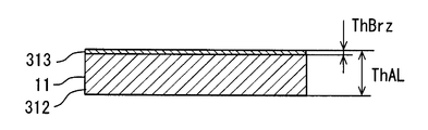
- the base material 11 is a product made from the single material which has aluminum as a main component.
- the substrate 11 has a main layer 312 and a brazing filler metal layer 313.
- the substrate 11 has an aluminum main layer 312 and a brazing filler metal layer 313.
- the brazing material layer 313 is an alloy layer mainly composed of aluminum.
- the brazing material layer 313 has a lower melting point than the main layer 312.
- the brazing filler metal layer 313 has a thickness ThBrz.
- the CNT alignment film 31 is formed on the brazing material layer 313.
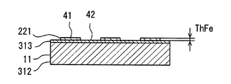
- the catalyst layer 221 is formed on the brazing material layer 313.
- the catalyst layer 221 is partially disposed so as to form the alignment region 41 and the non-formation region 42.
- the member 1 with CNT has a CNT alignment film 31 formed on the brazing material layer 313. Also in this embodiment, the CNT alignment film 31 forms the convex portion 32 and the concave portion 33.
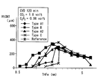
- FIG. 12 and 13 are graphs showing the relationship between the brazing filler metal component and the CNT height HtCNT.
- FIG. 14 shows the components of the brazing filler metal layer as a sample.
- the brazing material named Type A1 is characterized in that it contains aluminum as a main component and 2 to 3.2% of Zn.
- the brazing material named Type B is mainly composed of aluminum, Si is 0.6 to 0.9%, Cu is 0.2 to 0.4%, Mn is 1% to 2%, and Ti is 0.1 to The point which contains 0.2% is characteristic.
- the brazing material named Type A2 is characterized in that it contains less Zn than Type A1.
- the brazing material named Type C is mainly composed of aluminum and contains 9 to 11% of Si. This graph shows the CNT height HtCNT under the following conditions.
- the catalyst layer 21 is formed on the substrate 11 by sputtering.
- the catalyst layer 21 is formed by depositing iron in the range of 0 nm to 7 nm.
- the base material 11 is a foil having a thickness of 0.2 mm.
- the thickness ThBrz of the brazing filler metal layer 313 is about 10% or more of the thickness ThAL.
- the preheat treatment 187 is the same as the preceding embodiment.
- a CNT source gas is supplied onto the catalyst layer 21.
- the source gas is a mixture of acetylene (C 2 H 2 ) and carbon dioxide (CO 2 ) at a volume ratio of 1:30. Carbon dioxide accounts for 1.8 volume percent (vol%). Acetylene accounts for 0.06 volume percent (vol%).
- the volume CNT synthesis process is executed for 120 minutes.
- a reference product (Reference) having no brazing filler metal layer 313 is shown.
- the CNT alignment film 31 having the same height as the reference product is formed.
- the member 1 with CNT which can be utilized for a brazing process is provided.
- the member 1 with CNT is supplied to the brazing process.
- the member 1 with CNT is joined to another member so as to form an article having a predetermined shape in the brazing process.
- This embodiment is a modified example based on the preceding embodiment.
- the shape of the CNT alignment film 31 is controlled by the partial catalyst layer 221.
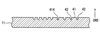
- elements that actively inhibit CNT synthesis and / or oriented growth may be provided on the surface of the substrate 11.
- a rough surface provided on the surface of the base material 11 is used as an inhibiting element.
- a rough surface is formed on the surface of the base material 11 by a plurality of grooves 414.
- the groove 414 is an inhibitory element.
- a rough surface is also an obstacle.
- the rough surface corresponds to one groove 414.
- One groove 414 is defined by a U-shaped concave surface.
- the groove 414 is a portion recessed from the original surface (plane) of the substrate 11.
- the U-shaped concave surface provides a surface that intersects the original surface of the substrate 11.
- the U-shaped concave surface is defined by a surface oriented in a direction different from the original surface (plane) of the substrate 11.
- the original surface of the base material 11 is left between the two grooves 414.
- the original surface of the substrate 11 provides an alignment region 41.
- the groove 414 provides a non-oriented region 43. More specifically, the grooves 414 inhibit the oriented growth of CNTs. In the non-alignment region 43, the CNTs are randomly arranged without being aligned along
- rough surface processing 481 is employed.
- the rough surface processing 481 forms a partial rough surface on the surface of the base material 11 by mechanical or chemical surface processing on the base material 11.
- the rough surface forms a rougher surface than other portions on the surface of the substrate 11.
- the rough surface is formed by various surfaces that are inclined with respect to a plane that defines the surface of the substrate 11.
- the rough surface can be formed by scratching the surface of the substrate 11.
- the rough surface may be formed by leaving the surface of the base material 11 before the polishing process.
- the rough surface processing 481 is also referred to as a pattern forming process for forming the CNT alignment film 31 in a predetermined pattern shape.
- the rough surface processing 481 is a process for providing an obstruction element.
- the rough surface processing 481 is a process of providing a rough surface that is more uneven than the surface of the alignment region 41 where the CNTs are formed in the non-alignment region 43 where the CNTs are not formed.
- the rough surface is formed by forming grooves 414 on the surface of the substrate 11.
- the base material 11 is an aluminum plate having a purity exceeding 99%.
- the substrate 11 may be made of an aluminum alloy.
- the groove 414 is formed by a scribe device used in a semiconductor manufacturing process.
- the groove 414 is a groove having a U-shaped cross section with a depth of 20 ⁇ m and a width of 10 ⁇ m.
- the remaining process steps 183-191 are the same as in the previous embodiment.
- a shape processing 185 for processing the base material 11 into a predetermined shape is executed.
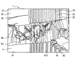
- FIG. 17 is an SEM image of the member 1 with CNT according to an example of this embodiment.
- FIG. 18 is a diagram for explaining each part in the SEM image.
- FIG. 17 and FIG. 18 correspond to perspective views of the fractured surface after a part of the CNT alignment film 31 is peeled off from the CNT-attached member 1 as viewed obliquely from above.
- the upper end surface TP of the CNT alignment film 31 appears in the upper part of the figure.
- the upper end surface TP is formed by the upper ends of many CNTs. Cracks CV generated when a part of the CNT alignment film 31 is peeled off are seen on the upper end surface TP.
- the fracture surface SD of the CNT alignment film 31 appears in the middle of the figure.
- the fracture surface SD is formed by the side surfaces of many CNTs. In the fracture surface SD, a number of vertical lines indicating the CNTs are seen. Further, on the fracture surface SD, random CNT clusters FZ generated when a part of the CNT alignment film 31 is peeled off can be seen. In the lower part of the figure, the surface of the substrate 11 appears. Grooves 414 are seen on the surface of the substrate 11.
- the convex portion 32 formed by the CNT alignment film 31 is located on the alignment region 41.
- a region in which the orientation is randomly disordered is seen on the groove 414. Due to the inclined surface forming the groove 414, the CNT grows in the vertical direction of the slope. Therefore, the CNTs growing from the opposing slopes inhibit the growth, and the growth of the CNT in the vertical direction of the substrate is prevented. The inhibition of the growth is noticeable on the upper end surface TP.
- a narrow recess 33 is formed at a position corresponding to the groove 414.
- the concave portion 33 is formed of CNTs having a reduced density (in other words, voids).
- the CNT alignment film 31 is not formed on the groove 414 due to the rough surface formed by the groove 414. As a result, a recess 33 is formed on the groove 414. It should be noted that the upper end portion of the CNT appears to be slightly inclined and swollen at the corner portion that is the boundary between the convex portion 32 and the concave portion 33.
- a region of the CNT alignment film 31 in which the CNTs are aligned and a region in which the CNTs extend at low density or randomly are formed on the base material 11.
- the shape of the CNT alignment film 31 is defined by the difference in density or alignment state of CNTs, that is, the presence or absence of alignment.
- the plurality of grooves 414 are formed to extend in parallel to each other. Instead, the plurality of grooves 414 may be formed so as to extend in a plurality of directions while intersecting each other. The plurality of grooves 414 may be formed to extend in a random direction in the non-oriented region 43.
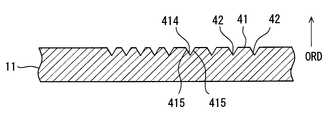
- FIG. 19 shows another example of the groove 414.
- the groove 414 has a V-shaped cross section.
- One groove 414 is defined by a pair of inclined surfaces 415 arranged in a V shape. Since the CNT grows perpendicularly to the surface, the slope 415 prevents the CNT from growing in the alignment direction ORD in the groove 414.
- the shape of the groove 414 is not limited to a U-shape or a V-shape.
- the groove 414 can have various shapes such as a semicircular cross section or a rectangular cross section.
- the long CNT alignment film 31 is formed as in the preceding embodiment. Furthermore, the CNT alignment film 31 can be partially formed on the substrate 11.
- the CNT alignment film 31 occupying a long and narrow area is formed.
- a plurality of elongated island-shaped CNT alignment films 31 are formed along the plurality of grooves 414. From another viewpoint, a plurality of linear recesses 33 are formed between the CNT alignment films 31.
- the plurality of island-shaped CNT alignment films 31 increase the heat exchange area with a heat medium such as air on the surface of the substrate 11.
- the elongated island-shaped CNT alignment film 31 is also plate-shaped.
- the plurality of plate-like CNT alignment films 31 have gaps between which a heat medium can be introduced.
- the plurality of plate-like CNT alignment films 31 exhibit a fin-like function when the heat medium flows into the gaps between them.
- the blocking element is provided by the groove 414 and / or the rough surface.
- a material layer that actively inhibits the growth and / or orientation of CNTs may be provided on the surface of the substrate 11.
- an organic material layer containing carbon (C) is used as an inhibiting element.
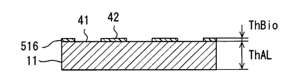
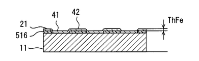
- an organic material layer 516 containing carbon is partially formed on the surface of the substrate 11.
- the organic material layer 516 can be formed using a readily available paint, sign pen, or the like.
- the organic material layer 516 is formed by painting a part of the surface of the substrate 11 with an oil-based sign pen.
- the organic material layer 516 is an inhibitory element.
- the organic material layer 516 is disposed in the non-oriented region 43. In other words, the alignment region 41 and the non-alignment region 43 are formed by the organic material layer 516.
- the catalyst layer 21 is also formed on the organic material layer 516.
- the organic material layer 516 is disposed adjacent to the catalyst layer 21.
- the organic material layer 516 reduces the activity of the catalyst in contact with the organic material layer 516.
- the organic material layer 516 may lose the activity of the catalyst. As a result, CNT does not grow on or be oriented on the organic material layer 516.
- the catalyst layer 21 is formed on the organic material layer 516.
- the organic material layer 516 may be provided on the catalyst layer 21.
- the organic material layer 516 is desirably provided adjacent to the catalyst layer 21. Note that the organic material layer 516 is also referred to as a carbon-containing material layer.
- the member 1 with CNT has a convex portion 32 and a concave portion 33.
- a trace of the organic material layer 516 is left under the recess 33. This trace is a residual layer formed when the organic material layer 516 is altered by a high temperature in the CNT synthesis process. Due to the high temperature in the CNT synthesis process, the organic material layer 516 mixes with the catalyst layer to form a residual layer. Therefore, the residual layer contains the elements constituting the catalyst layer 21 and carbon.
- the residual layer is also called a carbon-containing material layer or a carbon-containing residual layer.
- an organic layer forming process 581 is employed.
- the organic layer forming process 581 is a process of providing an inhibiting element.
- an organic material layer 516 containing carbon is provided in the non-oriented region 43 where CNTs are not formed.
- the organic layer forming process 581 is also referred to as a pattern forming process for forming the CNT alignment film 31 in a predetermined pattern shape.
- the remaining process steps 183-191 are the same as in the previous embodiment.
- a shape processing process 185 for processing the base material 11 into a predetermined shape is executed.
- the organic layer forming process 581 may be performed after the catalyst application process 183, and the catalyst application process 183 may be performed after the shape processing process 185 or the pre-heat treatment 187.
- the long CNT alignment film 31 is formed as in the preceding embodiment. Furthermore, the CNT alignment film 31 can be partially formed on the substrate 11.
- the CNT alignment film 31 can be formed on various shapes of base materials. Further, the CNT alignment film 31 can be formed in various shapes.
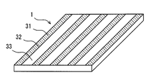
- the member 1 with CNT shown in FIG. 24 has a shape that can be called a plate or a foil.
- the thickness of the member 1 with CNT is set so that its own shape can be maintained.
- the CNT-attached member 1 provides a two-dimensional flat surface.
- the member 1 with CNT is a structure that can maintain the surface shape itself.
- the member 1 with CNT can be called a self-supporting two-dimensional structure.
- the CNT alignment film 31 forms a striped pattern. That is, the CNT alignment film 31 is formed so as to provide the convex portion 32 and the concave portion 33 arranged in a stripe shape.
- the member with CNT 1 illustrated in FIG. 25 has a shape that can be called a pipe.
- the thickness of the member 1 with CNT is set so that its own shape can be maintained.
- the member 1 with CNT provides the curved surface which spreads in three dimensions.
- the member 1 with CNT is a structure that can maintain the surface shape itself.
- the member 1 with CNT can be called a self-supporting three-dimensional structure.
- the CNT alignment film 31 is formed on a surface that spreads smoothly and continuously in three dimensions.
- the CNT alignment film 31 is formed so as to provide a convex portion 32 occupying a part of a three-dimensional surface and a concave portion 33 adjacent thereto.
- the CNT-attached member 1 can adopt various three-dimensional shapes such as blocks and meshes.
- the member 1 with CNT illustrated in FIG. 26 has a three-dimensional shape.
- the thickness of the member 1 with CNT is set so that its own shape can be maintained.
- the member 1 with CNT has a plurality of flat surfaces that spread so as to intersect each other.
- the CNT-attached member 1 is provided with a plurality of planes and a minute curved surface connecting them.
- the member 1 with CNT can be called a self-supporting three-dimensional structure.
- the base material is formed by bending an aluminum plate having a purity of 99% or more into a bracket shape.
- the base material is placed in an electric furnace and heated to 600 ° C. under an argon stream.
- vapor from ferrocene heated to 80 ° C. is included in the argon.
- the substrate is exposed to this atmosphere for 3 minutes.
- a CNT alignment film is synthesized by the same process as in the preceding embodiment.
- an inhibitory element may be provided on the surface of the base material.
- the flat plate may be processed into a three-dimensional shape, and then a CNT alignment film may be synthesized. According to this embodiment, the CNT alignment film is formed on the entire surface of the bracket-shaped substrate.
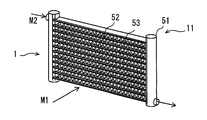
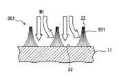
- the member with CNT 1 has a shape of a heat exchanger that provides heat exchange between the two media M1 and M2.
- the member 1 with CNT provides a complicated and various surface.
- the member 1 with CNT includes the base material 11 and the CNT alignment films 31 and 931 formed on the surface of the base material 11.
- a plurality of base materials 11 processed into a shape for forming a heat exchanger are combined to provide the shape of the heat exchanger.
- the base material 11 is aluminum and an aluminum alloy. On the surface of the base material 11, aluminum or aluminum alloy suitable for brazing and brazing is exposed.
- the base material 11 includes a pair of headers 51 and a plurality of tubes 52 that connect between the pair of headers 51. Furthermore, the base material 11 has a plurality of fins 53 for increasing the surface area with respect to the primary medium M1.
- the primary medium M1 flows on the outer surface of the member 1 with CNT.
- the secondary medium M ⁇ b> 2 flows through the pair of headers 51 and the plurality of tubes 52.
- a convex portion 32 and a concave portion 33 are formed by a CNT alignment film 31 on the surface of the member 1 with CNT.
- the primary medium M1 flows in contact with the CNT alignment film 31.
- heat exchange between the primary medium M1 and the CNT alignment film 31 may not be sufficiently obtained.
- FIG. 29 shows the shaped CNT alignment film 931 in this embodiment.
- the shaped CNT alignment film 931 has a trapezoidal shape.
- the shaped CNT alignment film 931 has a base part close to the base material 11 and an end part away from the base material 11. The base is thicker than the end.
- the shaped CNT alignment film 931 is shaped so as to be thicker on the substrate 11 side and become thinner as it is away from the substrate 11.
- the shaped CNT alignment film 931 includes CNTs extending slightly inclined in a bundle of island-like CNTs. However, it can be said that many CNTs included in the bundle of island-like CNTs are still oriented perpendicular to the plane of the surface of the substrate 11.
- the shaped CNT alignment film 931 Even in the shaped CNT alignment film 931, it can be said that the plurality of CNTs are aligned substantially perpendicular to the plane of the surface of the substrate 11.
- the shaped CNT alignment film 931 is easy to introduce the primary medium M1 into the recess 33. As a result, the member 1 with CNT which can exhibit high heat exchange performance as a heat exchanger is manufactured.
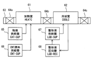
- the manufacturing apparatus of the member 1 with CNT includes a heating chamber (HEATC) 61 and a cooling chamber (COOLC) 62 for performing a cooling process.
- HEATC heating chamber
- COOLC cooling chamber
- the heating chamber 61 has a brazing material at least in part and accommodates a plurality of base materials 11 mainly composed of aluminum.
- the heating chamber melts the brazing material by heating the plurality of base materials 11 and brazes the plurality of base materials 11.
- the heating chamber 61 is a brazing furnace for brazing a plurality of members as a heat exchanger.
- the heating chamber 61 is also a reaction furnace for synthesizing CNTs. CNTs are synthesized simultaneously with brazing or before or after brazing.
- the cooling chamber 62 is a chamber for cooling the member 1 with CNT brazed in the heating chamber 61 and formed with the CNT alignment film 31.
- the cooling chamber 62 is also a shaping chamber for shaping the CNT alignment film 31.
- a preheating chamber for performing preheat treatment may be provided in front of the heating chamber 61.
- the manufacturing apparatus includes a transfer device 63 and gate devices 64a, 64b, and 64c for maintaining the atmosphere in the chambers 61 and 62.
- the gate devices 64a, 64b, 64c can be provided by air curtains or gate valves.
- the manufacturing apparatus includes a catalyst supplier (CAT-SUP) 65 that supplies a catalyst raw material to the heating chamber 61.
- the catalyst supplier 65 supplies the catalyst raw material so that a catalyst for synthesizing CNTs is provided on the surface of the substrate 11. Therefore, the heating chamber 61 is also a furnace for applying a catalyst to the surface of the substrate 11, in other words, a reaction furnace for forming a catalyst layer.
- the catalyst is applied to the substrate 11 simultaneously with brazing, before brazing, or after brazing.
- the catalyst is applied to the substrate 11 before CNT synthesis or simultaneously with CNT synthesis.
- the manufacturing apparatus includes a CNT raw material supplier (CNT-SUP) 66 that supplies the CNT raw material to the heating chamber 61.
- a raw material such as acetylene is supplied into the heating chamber 61 by the CNT raw material supplier 66 to synthesize CNTs.
- the CNT raw material supplier 66 supplies the CNT raw material to the heating chamber 61 so that brazing and synthesis of the CNT alignment film 31 are performed in the heating chamber 61.
- the CNT raw material supplier 66 can include a device for supplying acetylene, a device for supplying carbon dioxide, and a control device for controlling them.
- the control device supplies an appropriate amount of acetylene so that the required CNT is synthesized.
- the control device adjusts the supply amount of acetylene and carbon dioxide so that the volume ratio of acetylene and carbon dioxide is 1:10 or more and 1: 300 or less.
- the manufacturing apparatus has a shaping liquid supplier (LQD-SUP) 67 for supplying the shaping liquid.
- the shaping liquid supplier 67 is configured to supply the shaping liquid to the cooling chamber 62.
- the shaping liquid is, for example, ethanol.
- the shaping liquid is supplied as vapor and may be liquefied in the cooling chamber.
- the manufacturing apparatus has a shaping liquid collector (LQD-REC) 68 for collecting and reusing the shaping liquid.
- the shaping liquid collector 68 is configured to collect the shaping liquid from the cooling chamber 62.
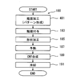
- a pattern forming process 981 and a shaping process 993 are executed.
- the pattern forming process 981 can employ any of the processes disclosed in the preceding embodiments. In this embodiment, a rough surface and / or an organic material layer as an inhibitory element is employed. These methods can partially form the CNT alignment film 31 without depending on the catalyst. Therefore, it can be executed before the shape processing 185.
- the shape processing process 185 is performed before the catalyst application process 183.
- the shape processing 185 is also a process of assembling a plurality of members forming the heat exchanger with a base material including a brazing material layer.
- a pre-heat treatment 187 is performed after the shape processing process 185. Further, after the pre-heat treatment 187, a catalyst application process 183 is performed.
- a catalyst is applied to the preheated base material 11 by supplying a catalyst-containing gas such as ferrocene vapor into the preheated heating chamber 61.
- the catalyst is applied to the surface of the substrate having the shape of a heat exchanger having a plurality of surfaces.
- a process 989 is executed instead of the CNT synthesis process 189 in the preceding embodiment.
- the process 989 is executed after the catalyst application process 183.
- Process 989 is a process in which brazing and CNT synthesis are performed in the common heating chamber 61.
- the shaping process 993 shapes the CNT alignment film 31 into a shape suitable for a heat exchanger.
- the shaping process 993 is also an agglomeration process in which a plurality of CNTs are collected or bundled so as to be thinly contracted at the tip of the bundle of island-like CNTs.
- Liquid can be used to collect multiple CNTs and reduce their spacing.
- the liquid can also be referred to as a shaping liquid.
- An example of the shaping liquid is a volatile liquid.
- the shaping liquid evaporates over time by reducing the shaping liquid vapor concentration in the atmospheric gas, raising the atmospheric temperature, or elapses of time.
- a plurality of CNTs are aggregated and bundled.
- a trapezoid shaped CNT alignment film 931 is obtained.
- the action of the shaping liquid at this time is similar to the action of a hair styling agent for preparing hair.
- An organic solvent can be used as the shaping liquid.
- long CNTs can be formed on the surface of the heat exchanger.
- the CNT alignment film 31 having a predetermined shape can be formed on the surface of the heat exchanger.
- the shape of the CNT alignment film 31 can be shaped into a shape suitable for a heat exchanger.
- FIG. 32 shows another example of the shaped CNT alignment film 931.
- the shape of the CNT alignment film 931 can be adjusted by changing various conditions in the manufacturing method.
- the shape in other words, the fineness of the CNT alignment film 931 can be adjusted by the density of the CNTs in the island-shaped group of CNT alignment films 931, the type of the shaping liquid, the evaporation rate of the shaping liquid, and the like.
- a heat medium such as air is more easily introduced between two adjacent CNT alignment films 931.
- the shaped CNT alignment film 931 increases the direct contact area between the substrate 11 and the heat medium.
- the shaped CNT alignment film 931 provides a fin shape that can be called a microfin.
- a passage shape that can be called a microchannel through which a heat medium can flow is provided.
- the disclosure herein is not limited to the illustrated embodiments.
- the disclosure encompasses the illustrated embodiments and variations by those skilled in the art based thereon.
- the disclosure is not limited to the combinations of parts and / or elements shown in the embodiments.
- the disclosure can be implemented in various combinations.
- the disclosure may have additional parts that can be added to the embodiments.
- the disclosure includes those in which parts and / or elements of the embodiments are omitted.
- the disclosure encompasses the replacement or combination of parts and / or elements between one embodiment and another.
- the technical scope disclosed is not limited to the description of the embodiments. Some technical scope disclosed is shown by the description of the scope of claims, and should be understood to include all modifications within the meaning and scope equivalent to the description of the scope of claims.
- the heat transfer product is exemplified as the use of the member with CNT.
- the member with CNT may be used for various purposes.
- it can be used for a member of an electric device such as a battery and a member for forming a structure.
- the partial CNT alignment film 31, that is, the CNT alignment film 31 formed in a predetermined pattern shape exhibits the effects required for each of various uses.
- the shaped CNT alignment film also exhibits an effect required for each of various uses.
- the base material 11 is made of aluminum or aluminum alloy.
- the base material may be a multilayer material having an aluminum layer or an aluminum alloy layer as a surface layer.
- the groove 414 is formed on the surface of the base material 11 using a scribing device.
- a rough surface or a groove may be formed using various metal processing methods such as cutting, rolling, polishing, and chemical corrosion.
Abstract
カーボンナノチューブ付部材1は、アルミニウムを主成分とする基材11と、配向方向ORDに沿って配向されたCNT配向膜31とを有する。CNT配向膜31を形成するカーボンナノチューブ/CNTは、200μm以上の長さをもつ。CNTは、アセチレン、水素、およびアルゴンの混合ガスを原料として合成される。さらに、触媒の活性を維持するために、二酸化炭素が添加される。アセチレン:二酸化炭素の比は、1:10から1:300に調整される。CNT配向膜31は、部分的に形成される。CNT配向膜31の形成範囲は、粗面、または炭素含有物によって、CNTの合成および/または配向された成長を阻害することによって設定される。
Description
この出願は、2016年2月26日に出願された日本特許出願2016-35991号を基礎出願とするものであり、当該基礎出願の開示内容は参照によってこの出願に組み込まれている。
この明細書における開示は、カーボンナノチューブ付部材、その製造方法およびその製造装置に関する。
カーボンナノチューブ(以下CNTという)の合成方法、すなわち製造方法として、基板上に触媒となる金属を形成し、加熱された炉内に配した後、原料となるアセチレンやエタノールなど炭素を含むガスを炉内に供給する方法が知られている。ガスの分解と触媒活性の維持のために、炉内の温度は通常700℃~800℃程度に維持される。しかし、この技術では、多様な基板材料への適用と、複数のCNTが一方向に配向され束状に配置されたCNT配向膜を求められる範囲に形成するパターン化と、CNTの長尺化とが困難であった。
特許文献1は、CNT配向膜を、基板上の所定の範囲に形成する技術を開示する。特許文献1は、CNT合成に必要な触媒を、求められる範囲に形成することにより、すなわちパターン化することにより、パターン化されたCNT配向膜の形成を可能としている。
特許文献2は、比較的低温でCNTを合成する方法を提案する。特許文献2は、600℃以上660℃未満においてCNTを合成するために、通常の熱分解に加え、先端放電型プラズマCVDを用いる。これにより、H2ガスとCH4とを活性化し、CNT配向膜を合成している。
特許文献3は、アルミニウムやマグネシウムの上にCNTを合成する方法を提案する。
従来技術として列挙された先行技術文献の記載内容は、この明細書における技術的要素の説明として、参照により援用される。
特許文献1の手法は、パターン化された触媒を、求められる場所に形成する手段が必要である。たとえば、ステンシルマスクやフォトリソグラフィなどを必要とするから、製造工程が複雑になる。また、特許文献1の手法は、平坦な基板への適用に限られる。この結果、例えば、立体的な構造体の表面へ、パターン化されたCNT配向膜を形成することができない。
特許文献2の手法では、触媒の活性が、長時間に渡って維持されない。このため、長尺のCNTを得ることができない。
特許文献3の手法では、CNTはランダムに配置されるから、配向膜が形成されない。
上述の観点において、または言及されていない他の観点において、カーボンナノチューブ付部材、その製造方法、およびその製造装置にはさらなる改良が求められている。
開示されるひとつの目的は、長いCNTが配向されたカーボンナノチューブ付部材、その製造方法、およびその製造装置を提供することである。
開示される他のひとつの目的は、CNT配向膜が部分的に形成されたカーボンナノチューブ付部材、その製造方法、およびその製造装置を提供することである。
開示されるさらに他のひとつの目的は、アルミニウムを主成分とする基材の表面上に長いCNTにより形成されたCNT配向膜が形成されたカーボンナノチューブ付部材、その製造方法、およびその製造装置を提供することである。
開示されるさらに他のひとつの目的は、簡単な装置によってアルミニウムを主成分とする基材のろう付けと、CNTの合成とが可能なCNT配向膜が形成されたカーボンナノチューブ付部材、その製造方法、およびその製造装置を提供することである。
ここに開示されたカーボンナノチューブ付部材は、アルミニウムを主成分とする基材(11)と、長さ200μm以上の複数のカーボンナノチューブが所定の配向方向に沿って配向されており、基材の表面に配置されたCNT配向膜(31、931)とを備える。
開示されるカーボンナノチューブ付部材によると、アルミニウムを主成分とする基材に、長さ200μm以上の複数のカーボンナノチューブが配向されたCNT配向膜を設けることができる。
ここに開示されたカーボンナノチューブ付部材の製造方法は、アルミニウムを主成分とする基材の表面にカーボンナノチューブを合成するための触媒(21、221)を配置する工程(183、283)と、触媒の活性を維持するための二酸化炭素を供給するとともに、カーボンナノチューブの原料としてのアセチレンと二酸化炭素との体積比が1:10以上である雰囲気中において基材の表面にカーボンナノチューブを合成する工程(189、989)とを備える。
開示される製造方法によると、二酸化炭素によって低温においても触媒の活性が維持される。よって、低温においてカーボンナノチューブの合成が可能となる。この結果、アルミニウムを主成分とする基材の表面にCNT配向膜を形成することができる。
ここに開示されたカーボンナノチューブ付部材の製造装置は、少なくとも一部にろう材(313)を有しており、アルミニウムを主成分とする基材(11)を収容し、基材を加熱することによりろう材を溶融させ、基材をろう付けする加熱室(61)、および、ろう付けと、複数のカーボンナノチューブが所定の配向方向に沿って配向されたCNT配向膜(31、931)の基材の表面における合成とを、加熱室において行うように、加熱室にカーボンナノチューブの原料を供給する原料供給器(66)を備える。
開示される製造装置によると、ろう付けと、カーボンナノチューブの合成とを、共通の加熱室において実行することができる。
この明細書における開示された複数の態様は、それぞれの目的を達成するために、互いに異なる技術的手段を採用する。請求の範囲およびこの項に記載した括弧内の符号は、後述する実施形態の部分との対応関係を例示的に示すものであって、技術的範囲を限定することを意図するものではない。この明細書に開示される目的、特徴、および効果は、後続の詳細な説明、および添付の図面を参照することによってより明確になる。
図面を参照しながら、複数の実施形態を説明する。複数の実施形態において、機能的におよび/または構造的に対応する部分および/または関連付けられる部分には同一の参照符号、または百以上の位が異なる参照符号が付される場合がある。対応する部分および/または関連付けられる部分については、他の実施形態の説明を参照することができる。
第1実施形態
この実施形態では、カーボンナノチューブ付部材(CNT付部材)とその製造方法とが開示される。カーボンナノチューブ配向膜(CNT配向膜)は、多数のカーボンナノチューブ(CNT)が配向された膜である。CNT配向膜は、金属製の基材の表面上に配置されている。一例において、CNTは、基材の表面が提供する平面に対して垂直に延びるように配向されている。CNT付部材は、CNTで被覆された部材、CNT複合材料、またはCNT構造体とも呼ばれる。図1、図2、図3は、CNT付部材の製造工程の各段階における材料の形状を示す。
この実施形態では、カーボンナノチューブ付部材(CNT付部材)とその製造方法とが開示される。カーボンナノチューブ配向膜(CNT配向膜)は、多数のカーボンナノチューブ(CNT)が配向された膜である。CNT配向膜は、金属製の基材の表面上に配置されている。一例において、CNTは、基材の表面が提供する平面に対して垂直に延びるように配向されている。CNT付部材は、CNTで被覆された部材、CNT複合材料、またはCNT構造体とも呼ばれる。図1、図2、図3は、CNT付部材の製造工程の各段階における材料の形状を示す。
図1は、CNTが形成される基材11の断面を示す。基材11は、アルミニウム製の金属板である。基材11は、純度99%を上回るアルミニウム製またはアルミニウム合金製である。アルミニウム合金には、添加金属として、Si、Zn、Ti、Mn、Cu、Fe、Mg、およびCrのなかから選択される少なくともひとつまたは複数を含むことができる。基材11は、厚さThALを有する。基材11は、任意の厚さを有することができる。例えば、基材11は、箔と呼びうる厚さをもつ場合がある。基材11は、二次元に広がる平面を提供する。基材11は、表面形状を自ら維持可能な構造物である。また、基材11は、放熱器または熱交換器などの熱伝達製品を形成しうる構造部材としての厚さをもつ場合がある。
図2は、基材11の表面に形成された触媒層21を示す。触媒層21は、CNTを合成するための金属材料によって形成されている。触媒層21は、例えば鉄、ニッケル、コバルトなどによって形成されている。この実施形態では、基材11の表面の全体を覆うように触媒層21が形成されている。触媒層21は、厚さThFeを有する。
図3は、CNT付部材1の断面を示す。基材11の表面に触媒層21が配置されている。触媒層21の上には、CNT配向膜31が形成されている。CNT配向膜31は、多数のCNTを有する。これら多数のCNTは、配向方向ORDに向けて配向されている。図示の例では、多数のCNTは、CNTの長手方向が、基材11の表面に対して垂直方向に沿って延びるように配向されている。配向方向ORDは、基材11の表面に対して傾斜していてもよい。なお、CNTは、やや蛇行しながら配向方向ORDに沿って延びている。CNT配向膜31は、配向方向ORDに沿って高さHtCNTを有する。
CNT配向膜31は、基材11の表面の全体にわたって広がっている。CNT配向膜31は、基材11の上に凸部32を形成するように突出している。高さHtCNTは、ひとつのCNTの長さに概略相当する。ひとつのCNTは屈曲しながら配向方向ORDへ延びている。よって、ひとつのCNTの長さは、高さHtCNTより長い。高さHtCNTは、CNTがもつ高い熱伝導性を、放熱器または熱交換器などの熱伝達製品として有効に利用しうる高さである。例えば、CNTが空気と接触する場合、CNT配向膜31は空気に対して広い表面積を提供する。さらに、CNTは、基材11からCNTの長さ方向に沿って高い熱伝導率を提供する。この結果、CNT配向膜31は、空気と基材11との間の熱交換を促進する。
図4において、CNT付部材1の製造方法180は、基材11の表面上にCNT配向膜31を形成するための複数の段階を有している。製造方法180は、CNTを合成するための加熱炉の中に基材11を配置した後に実行される。図示される順序は一例であり、付加的な要請に応じて変更される場合がある。
製造方法180は、複数の処理、すなわち工程を有する。製造方法180は、触媒付与処理183を有する。触媒付与処理183は、基材11の表面上に触媒層21を形成する。触媒層21は、液コート、蒸着、スパッタリング、気相中添加など多様な手法のいずれかによって形成することができる。製造方法180は、形状加工処理185を有することができる。形状加工処理185は、オプションとして用意されている。形状加工処理185では、基材11が所定の形状、例えば三次元的な形状に加工される。ここでは、切断、曲げなどの機械的な加工が加えられる。製造方法180は、予熱処理187を有する。予熱処理187は、基材11と触媒層21とをCNTの合成に適した温度に予熱する。
製造方法180は、CNT合成処理189を有する。CNT合成処理189では、加熱炉の中にCNTの原料が供給される。原料は、加熱炉の中で加熱され、分解される。触媒層21を形成する触媒の上に、CNTが合成される。CNTは、配向方向ORDに沿って成長する。この結果、CNT配向膜31が形成される。製造方法180は、冷却処理191を有する。冷却処理191は、CNT付部材1を、例えば常温まで冷却する。
図5は、製造方法180における複数のパラメータとCNT高さHtCNT(μm:マイクロメートル)との関係を示すグラフである。パラメータは、CNT原料の体積比CO2/C2H2(v/v)、および触媒層21の厚さThFe(nm:ナノメートル)である。このグラフは、下記の条件におけるCNT高さHtCNTを示している。
触媒付与処理183において、基材11の上にスパッタ法により触媒層21が形成される。触媒層21は、鉄を0nmから8nmの範囲で堆積させることによって形成されている。基材11は、純度99%を上回るアルミニウム製であって、厚さ0.2mmの箔である。この例では、形状加工処理185は実行されない。
予熱処理187において、基材11と触媒層21とは、アルゴンと水素との混合ガスの中で600℃まで昇温され、600℃の雰囲気中で5分間保持される。
CNT合成処理189において、触媒層21の上に、CNTの原料ガスが供給される。原料ガスは、アセチレン(C2H2)と二酸化炭素(CO2)とを、体積比1:0~1:266で混合したものである。この結果、CNT合成処理における雰囲気、すなわち原料ガスは、アセチレン、水素、二酸化炭素、およびアルゴンの混合ガスである。二酸化炭素は、触媒の活性を維持するためのガスとして添加されている。CNT合成処理189は、CNTの原料としてのアセチレンと二酸化炭素との体積比が1:10以上1:300以下である雰囲気中において基材11の表面にCNTを合成する。CNT合成は、熱CVD処理とも呼ぶことができる。CNT合成処理189は、120分間実行される。なお、製造装置は、アセチレンの量と、二酸化炭素の量とを調節する制御装置を備える。
図示されるように、体積比1:3.3~1:266の範囲、または体積比1:10~1:266の範囲においてCNT配向膜31の成長が促進されている。すべての体積比において、触媒層21の厚さThFeが約2nm~3nmであるときにCNT配向膜31の高さHtCNTが最高値となっている。すべての体積比において、400μmを上回る高さのCNT配向膜31が得られている。
図示されるように、体積比1:3.3において、400μmを上回る高さのCNT配向膜31が得られている。体積比1:10では、3nmを上回る厚さの触媒層21において400μmを上回る高さのCNT配向膜31が得られている。体積比1:100において最も高いCNT配向膜31が得られている。さらに、体積比1:266においても、500μm、または600μmを上回る高さのCNT配向膜31が得られている。
発明者らの知見によると、体積比1:10未満では、CNTの合成が不安定であると考えられた。その一方で、体積比1:300でも、高いCNT配向膜31が合成されると考えられた。よって、体積比1:10以上、1:300以下の範囲内においては、200μm、300μm、または400μm、さらに望ましくは500μmを上回る高さのCNT配向膜31が得られると考えられる。
CNT原料中のアセチレンと二酸化炭素の体積比は、1:10以上、1:300以下に設定することができる。CNT原料の体積比は、1:30以上、1:100以下に設定されてもよい。触媒層21の厚さThFeは、触媒が鉄である場合、3nm付近に設定することができる。例えば、触媒層21の厚さThFeは、2nm以上に設定することができる。触媒層21の厚さThFeは、3nm以上に設定されてもよい。これらの設定は、高いCNT配向膜31を安定的に合成することを可能とする。触媒層21の厚さThFeは、6nm以下に設定することができる。触媒層21の厚さThFeは、5nm以下に設定されてもよい。これらの下限と上限とは、所定の高さ以上のCNT配向膜31を得るように選択することができる。高さHtCNTの傾斜は、触媒層21の厚さThFeが3nmを上回る領域において緩い。そこで、触媒層21の厚さThFeは、比較的厚い領域、例えば3nm以上、5nm以下に設定されてもよい。
この実施形態によると、アルミニウム製の基材11の上に、高いCNT配向膜31が形成される。具体的には、200μm以上、または200μmを上回る高さをもつCNT配向膜31が得られる。さらに、300μm以上の高さをもつCNT配向膜31が得られる。さらに望ましい態様では、400μm以上の高さをもつCNT配向膜31が得られる。
第2実施形態
この実施形態は、先行する実施形態を基礎的形態とする変形例である。上記実施形態では、CNT配向膜31は、基材11の表面の全体に形成されている。これに代えて、この実施形態では、CNT配向膜31は、基材11の表面の一部分に形成される。
この実施形態は、先行する実施形態を基礎的形態とする変形例である。上記実施形態では、CNT配向膜31は、基材11の表面の全体に形成されている。これに代えて、この実施形態では、CNT配向膜31は、基材11の表面の一部分に形成される。
図6において、基材11の表面上には、基材11の表面の一部分だけを覆うように部分的な触媒層221が形成されている。触媒層221は、CNT配向膜31の形成が意図される配向領域41に形成されている。触媒層221は、CNT配向膜31の形成が意図されない非形成領域42には形成されていない。この結果、基材11の表面上には、配向領域41と、非形成領域42とが形成される。非形成領域42ではCNT配向膜31が合成されないか、または長く成長しない。
図7において、CNT付部材1は、凸部32と、凹部33とを有する。凸部32は、基材11から突出するように形成された長いCNTの束である。凸部32は、島状のCNT配向膜31とも呼ぶことができる。基材11の表面上には、任意の断面において互いに離れた複数の凸部32が形成されている。凹部33は、2つの凸部32の間に位置している。凹部33においては、CNTが合成されていないか、またはCNTがCNT配向膜31より乱れて伸びている。
図8において、この実施形態の製造方法では、触媒付与処理283が採用されている。触媒付与処理283は、触媒を配置する工程である。触媒付与処理283は、部分的な触媒層221を形成する。触媒層221は、ステンシルマスクまたはフォトリソグラフィなどを利用して形成することができる。触媒付与処理283は、CNT配向膜31を所定のパターン形状に形成するためのパターン形成処理とも呼ばれる。触媒付与処理283は、基材11の表面のうち、CNTが形成されない非形成領域42に触媒を設けることなく、CNTが形成される配向領域41に触媒を設ける工程である。この実施形態では、製造工程におけるパラメータは、先行する実施形態と同じである。後続の処理185-191は、先行する実施形態と同じである。触媒を設ける工程の後に、基材11を所定の形状に加工する形状加工処理185が実行される。
この実施形態でも、先行する実施形態と同様に、長いCNT配向膜31が形成される。さらに、CNT配向膜31を、基材11上に部分的に形成することができる。
第3実施形態
この実施形態は、先行する実施形態を基礎的形態とする変形例である。上記実施形態では、基材11は、アルミニウムを主成分とする単一材料製である。これに代えて、この実施形態では、基材11は、主層312とろう材層313とを有する。
この実施形態は、先行する実施形態を基礎的形態とする変形例である。上記実施形態では、基材11は、アルミニウムを主成分とする単一材料製である。これに代えて、この実施形態では、基材11は、主層312とろう材層313とを有する。
図9において、基材11は、アルミニウム製の主層312と、ろう材層313とを有する。ろう材層313は、アルミニウムを主成分とする合金層である。ろう材層313は、主層312より低い融点をもつ。ろう材層313は、厚さThBrzを有する。この実施形態では、ろう材層313の上に、CNT配向膜31が形成される。
図10に図示されるように、ろう材層313の上に、触媒層221が形成される。触媒層221は、配向領域41と非形成領域42とを形成するように部分的に配置される。
図11において、CNT付部材1は、ろう材層313の上に形成されたCNT配向膜31を有する。この実施形態でも、CNT配向膜31は、凸部32と凹部33とを形成する。
図12、図13は、ろう材の成分とCNT高さHtCNTとの関係を示すグラフである。図14は、試料とされたろう材層の成分を示す。TypeA1と名付けられたろう材は、アルミニウムを主成分とし、Znを2~3.2%含有する点が特徴的である。TypeBと名付けられたろう材は、アルミニウムを主成分とし、Siを0.6~0.9%、Cuを0.2~0.4%、Mnを1%~2%、Tiを0.1~0.2%含有する点が特徴的である。TypeA2と名付けられたろう材は、TypeA1よりZnが少ない点が特徴的である。TypeCと名付けられたろう材は、アルミニウムを主成分とし、Siを9~11%含有させたものである。このグラフは、下記の条件におけるCNT高さHtCNTを示している。 触媒付与処理183において、基材11の上にスパッタ法により触媒層21が形成される。触媒層21は、鉄を0nmから7nmの範囲で堆積させることによって形成されている。基材11は、厚さ0.2mmの箔である。ろう材層313の厚さThBrzは、厚さThALの約10%以上である。予熱処理187は先行する実施形態と同じである。
CNT合成処理189において、触媒層21の上に、CNTの原料ガスが供給される。原料ガスは、アセチレン(C2H2)と二酸化炭素(CO2)とを、体積比1:30で混合したものである。二酸化炭素は1.8体積百分率(vol%)を占める。アセチレンは0.06体積百分率(vol%)を占める。体積CNT合成処理は、120分間実行される。
図中には、ろう材層313をもたない基準品(Reference)が図示されている。図示されるように、ろう材層313があっても、基準品と同様の高さをもつCNT配向膜31が形成される。この実施形態によると、ろう付け工程に利用可能なCNT付部材1が提供される。この場合、CNT付部材1は、ろう付け工程に供給される。CNT付部材1は、ろう付け工程において所定の形状の物品をなすように他の部材と接合される。
第4実施形態
この実施形態は、先行する実施形態を基礎的形態とする変形例である。上記実施形態では、部分的な触媒層221によって、CNT配向膜31の形状が制御される。これに代えて、CNTの合成および/または配向された成長を積極的に阻害する要素を基材11の表面上に設けてもよい。この実施形態は、阻害要素として、基材11の表面に設けられた粗面を利用する。
この実施形態は、先行する実施形態を基礎的形態とする変形例である。上記実施形態では、部分的な触媒層221によって、CNT配向膜31の形状が制御される。これに代えて、CNTの合成および/または配向された成長を積極的に阻害する要素を基材11の表面上に設けてもよい。この実施形態は、阻害要素として、基材11の表面に設けられた粗面を利用する。
図15において、基材11の表面上には、複数の溝414によって粗面が形成されている。この実施形態では、溝414が阻害要素である。また、粗面も阻害要素である。粗面は、ひとつの溝414に対応する。ひとつの溝414は、U字型の凹面によって区画形成されている。溝414は、基材11の本来の表面(平面)より凹んだ部分である。U字型の凹面は、基材11の本来の表面に対して交差する面を提供している。U字型の凹面は、基材11の本来の表面(平面)とは異なる方向を指向する面によって区画形成されている。2つの溝414の間には、基材11の本来の表面が残されている。基材11の本来の表面は、配向領域41を提供する。溝414は、非配向領域43を提供する。より具体的には、溝414は、CNTの配向された成長を阻害する。非配向領域43では、CNTは配向方向ORDに沿って配向されることなく、ランダムに配置されている。
図16において、この実施形態の製造方法では、粗面加工処理481が採用されている。粗面加工処理481は、基材11に対する機械的または化学的な表面加工によって、基材11の表面に部分的な粗面を形成する。粗面は、基材11の表面上の他の部位よりも粗い表面を形成する。粗面は、基材11の表面を規定する平面に対して傾斜する多様な面によって形成される。粗面は、基材11の表面にキズを付けることによって形成することができる。また、粗面は、基材11の研磨加工前の表面を残すことによって形成されてもよい。粗面加工処理481は、CNT配向膜31を所定のパターン形状に形成するためのパターン形成処理とも呼ばれる。粗面加工処理481は、阻害要素を設けるための工程である。粗面加工処理481は、CNTが形成される配向領域41の表面よりも凹凸状の粗面をCNTが形成されない非配向領域43に設ける工程である。この実施形態では、粗面は、基材11の表面に溝414を形成することによって形成される。
ひとつの例において、基材11は、純度99%を上回るアルミニウム製の板である。なお、基材11はアルミニウム合金製でもよい。粗面加工処理481において、溝414は、半導体製造工程において使用されるスクライブ装置によって形成される。溝414は、深さ20μm、幅10μmのU字型の断面をもつ溝である。残る処理工程183-191は先行する実施形態と同じである。粗面加工処理481によって提供される阻害要素を設ける工程の後に、基材11を所定の形状に加工する形状加工処理185が実行される。
図17は、この実施形態の一例によるCNT付部材1のSEM画像である。図18は、SEM画像における各部を説明するための線図である。図17および図18は、CNT付部材1からCNT配向膜31の一部を剥ぎ取った後の破断面を斜め上から見た斜視図に相当する。図の上部には、CNT配向膜31の上端面TPが表れている。上端面TPは、多数のCNTの上端によって形成されている。上端面TPには、CNT配向膜31の一部を剥ぎ取る際に発生したひび割れCVが見られる。図の中部には、CNT配向膜31の破断面SDが表れている。破断面SDは、多数のCNTの側面によって形成されている。破断面SDには、CNTを示す縦方向の多数の条線が見られる。また、破断面SDには、CNT配向膜31の一部を剥ぎ取る際に発生したランダムなCNTの塊FZが見られる。図の下部には、基材11の表面が表れている。基材11の表面には溝414が見られる。
図示されるように、平面状の配向領域41の上には、配向された多数のCNTが見られる。このため、配向領域41の上には、CNT配向膜31によって形成された凸部32が位置している。
一方、溝414の上には、配向がランダムに乱れた領域が見られる。溝414を形成する傾斜した面に起因して、CNTは斜面垂直方向に成長するため、対向する斜面から成長するCNT同士が成長を阻害し、CNTの基板垂直方向への成長が妨げられる。成長の阻害は、上端面TPにおいて顕著に表れている。溝414に対応する位置には、細い凹部33が形成されている。この凹部33は、密度の低下したCNT(換言すると空隙)によって形成されている。溝414によって形成された粗面によって溝414の上にはCNT配向膜31が形成されない。この結果、溝414の上には、凹部33が形成されている。なお、凸部32と凹部33との境界となる角部では、CNTの上端部がやや傾き、膨らんだように見える。
この実施形態では、基材11の上に、CNTが配向されたCNT配向膜31の領域と、CNTが低密度ないしランダムに延びる領域とが形成されている。言い換えると、CNTの密度ないし配向状態の差、端的には配向の有無によってCNT配向膜31の形状が規定されている。なお、この実施形態では、複数の溝414は、互いに平行に延びるように形成されている。これに代えて、複数の溝414は、互いに交差しながら、複数の方向に延びるように形成されていてもよい。複数の溝414は、非配向領域43においてランダムな方向に延びるように形成されていてもよい。
図19は、溝414の他の例を示している。溝414は、V字型の断面を有する。ひとつの溝414は、V字型に配置された一対の斜面415によって区画形成されている。CNTは、面に対して垂直に成長してゆくから、斜面415は、溝414の中において、CNTが配向方向ORDへ成長することを妨げる。なお、溝414の形状は、U字型、V字型に限定されない。溝414は、例えば、半円形断面、または長方形断面など多様な形状をもつことができる。 この実施形態でも、先行する実施形態と同様に、長いCNT配向膜31が形成される。さらに、CNT配向膜31を、基材11上に部分的に形成することができる。また、細長い範囲を占めるCNT配向膜31が形成される。複数の溝414に沿って複数の細長い島状のCNT配向膜31が形成される。別の観点では、複数の線状の凹部33がCNT配向膜31の間に形成される。複数の島状のCNT配向膜31は、基材11の表面において空気などの熱媒体との熱交換面積を増加させる。細長い島状のCNT配向膜31は、板状でもある。複数の板状のCNT配向膜31は、それらの間に、熱媒体を導入可能な隙間を有している。複数の板状CNT配向膜31は、それらの間のすきまに熱媒体が流れこむことで、フィンのような機能を発揮する。
第5実施形態
この実施形態は、先行する実施形態を基礎的形態とする変形例である。上記実施形態では、溝414および/または粗面によって阻害要素が提供されている。これに代えて、CNTの成長および/または配向を積極的に阻害する材料層を基材11の表面上に設けてもよい。この実施形態は、阻害要素として、炭素(C)を含む有機材料層が利用される。
この実施形態は、先行する実施形態を基礎的形態とする変形例である。上記実施形態では、溝414および/または粗面によって阻害要素が提供されている。これに代えて、CNTの成長および/または配向を積極的に阻害する材料層を基材11の表面上に設けてもよい。この実施形態は、阻害要素として、炭素(C)を含む有機材料層が利用される。
図20において、基材11の表面上には、炭素を含む有機材料層516が部分的に形成されている。有機材料層516は、容易に入手可能な塗料、サインペンなどによって形成することができる。一例では、基材11の表面の一部を油性サインペンによって塗り潰すことによって有機材料層516が形成されている。この実施形態では、有機材料層516が阻害要素である。有機材料層516は、非配向領域43に配置されている。言い換えると、有機材料層516によって配向領域41と非配向領域43とが形成されている。
図21に図示されるように、触媒層21は、有機材料層516の上にも形成される。有機材料層516は、触媒層21に隣接して配置されている。有機材料層516は、有機材料層516と接する触媒の活性を低下させる。有機材料層516は、触媒の活性を失わせる場合もある。この結果、有機材料層516の上にはCNTが成長しないか、または配向されない。この実施形態では、有機材料層516の上に触媒層21が形成される。これに代えて、触媒層21の上に有機材料層516が設けられてもよい。有機材料層516は、触媒層21に隣接して設けられることが望ましい。なお、有機材料層516は、炭素含有材料層とも呼ばれる。
図22において、CNT付部材1は、凸部32と、凹部33とを有する。凹部33の下に有機材料層516の痕跡が残されている。この痕跡は、CNT合成処理における高温によって有機材料層516が変質することによって形成される残留層である。CNT合成処理における高温に起因して、有機材料層516は、触媒層と混じりあい、残留層を形成する。よって、残留層は触媒層21を構成する元素と炭素とを含む。残留層は、炭素含有材料層とも、炭素含有残留層とも呼ばれる。
図23において、この実施形態の製造方法では、有機層形成処理581が採用されている。有機層形成処理581は、阻害要素を設ける工程である。有機層形成処理581は、CNTが形成されない非配向領域43に、炭素を含む有機材料層516が設けられる。有機層形成処理581は、CNT配向膜31を所定のパターン形状に形成するためのパターン形成処理とも呼ばれる。残る処理工程183-191は先行する実施形態と同じである。有機層形成処理581によって提供される阻害要素を設ける工程の後に、基材11を所定の形状に加工する形状加工処理185が実行される。有機層形成処理581は触媒付与処理183の後に行っても良いし、触媒付与処理183は形状加工処理185の後ないし予熱処理187の後に行っても良い。
この実施形態でも、先行する実施形態と同様に、長いCNT配向膜31が形成される。さらに、CNT配向膜31を、基材11上に部分的に形成することができる。
第6実施形態
この実施形態は、先行する実施形態を基礎的形態とする変形例である。CNT配向膜31は、多様な形状の基材に形成することができる。また、CNT配向膜31は、多様な形状に形成することができる。
この実施形態は、先行する実施形態を基礎的形態とする変形例である。CNT配向膜31は、多様な形状の基材に形成することができる。また、CNT配向膜31は、多様な形状に形成することができる。
図24に図示されるCNT付部材1は、板または箔と呼べる形状を有する。CNT付部材1の厚さなどは、自らの形状を維持できるように設定されている。CNT付部材1は、二次元に広がる平面を提供する。CNT付部材1は、表面形状を自ら維持可能な構造物である。CNT付部材1は、自立可能な二次元構造体と呼ぶことができる。CNT配向膜31は、縞模様を形成している。すなわち、CNT配向膜31は、ストライプ状に並べられた凸部32と凹部33とを提供するように形成されている。
第7実施形態
この実施形態は、先行する実施形態を基礎的形態とする変形例である。図25に図示されるCNT付部材1は、パイプと呼べる形状を有する。CNT付部材1の厚さなどは、自らの形状を維持できるように設定されている。CNT付部材1は、三次元に広がる曲面を提供する。CNT付部材1は、表面形状を自ら維持可能な構造物である。CNT付部材1は、自立可能な三次元構造体と呼ぶことができる。CNT配向膜31は、三次元に連続的に滑らかに広がる面上に形成されている。CNT配向膜31は、三次元の面の一部を占める凸部32と、それに隣接する凹部33とを提供するように形成されている。CNT付部材1は、ブロック、メッシュなど、多様な立体形状を採用することができる。
この実施形態は、先行する実施形態を基礎的形態とする変形例である。図25に図示されるCNT付部材1は、パイプと呼べる形状を有する。CNT付部材1の厚さなどは、自らの形状を維持できるように設定されている。CNT付部材1は、三次元に広がる曲面を提供する。CNT付部材1は、表面形状を自ら維持可能な構造物である。CNT付部材1は、自立可能な三次元構造体と呼ぶことができる。CNT配向膜31は、三次元に連続的に滑らかに広がる面上に形成されている。CNT配向膜31は、三次元の面の一部を占める凸部32と、それに隣接する凹部33とを提供するように形成されている。CNT付部材1は、ブロック、メッシュなど、多様な立体形状を採用することができる。
第8実施形態
この実施形態は、先行する実施形態を基礎的形態とする変形例である。図26に図示されるCNT付部材1は、立体的な形状を有する。CNT付部材1の厚さなどは、自らの形状を維持できるように設定されている。CNT付部材1は、互いに交差するように広がる複数の平面を有する。CNT付部材1は、複数の平面と、それらの間をつなぐ微小な曲面が提供されている。CNT付部材1は、自立可能な三次元構造体と呼ぶことができる。
この実施形態は、先行する実施形態を基礎的形態とする変形例である。図26に図示されるCNT付部材1は、立体的な形状を有する。CNT付部材1の厚さなどは、自らの形状を維持できるように設定されている。CNT付部材1は、互いに交差するように広がる複数の平面を有する。CNT付部材1は、複数の平面と、それらの間をつなぐ微小な曲面が提供されている。CNT付部材1は、自立可能な三次元構造体と呼ぶことができる。
この実施形態では、純度99%を上回るアルミニウム製の板をブラケット状に曲げることによって基材が形成されている。この実施形態の製造方法では、基材は、電気炉内へ設置され、アルゴン気流の下で、600℃まで加熱される。次に、80℃に加熱されたフェロセンからの蒸気をアルゴンに含ませる。基材は、この雰囲気内に3分間にわたって暴露される。続いて、先行する実施形態と同様の処理によってCNT配向膜が合成される。
なお、基材の表面に阻害要素が設けられてもよい。また、平板に阻害要素を設けた後に、平板を立体形状に加工し、その後、CNT配向膜を合成しても良い。この実施形態によると、ブラケット状の基材の表面全体にCNT配向膜が形成される。
第9実施形態
この実施形態は、先行する実施形態を基礎的形態とする変形例である。図27に図示されるように、CNT付部材1は、2つの媒体M1、M2の間の熱交換を提供する熱交換器の形状を有している。CNT付部材1は、複雑で多様な面を提供している。この実施形態でも、CNT付部材1は、基材11と、基材11の表面上に形成されたCNT配向膜31、931とを有する。
この実施形態は、先行する実施形態を基礎的形態とする変形例である。図27に図示されるように、CNT付部材1は、2つの媒体M1、M2の間の熱交換を提供する熱交換器の形状を有している。CNT付部材1は、複雑で多様な面を提供している。この実施形態でも、CNT付部材1は、基材11と、基材11の表面上に形成されたCNT配向膜31、931とを有する。
この実施形態では、熱交換器を形成するための形状に加工された複数の基材11が組み合わせられて熱交換器の形状を提供している。基材11は、アルミニウムおよびアルミニウム合金である。基材11の表面には、ろう材およびろう付けに適したアルミニウムまたはアルミニウム合金が露出している。基材11は、一対のヘッダ51、および一対のヘッダ51の間を連結する複数のチューブ52を有する。さらに、基材11は、一次媒体M1に対する表面積を増加させるための複数のフィン53を有する。一次媒体M1は、CNT付部材1の外表面上を流れる。二次媒体M2は、一対のヘッダ51と複数のチューブ52との中を流れる。
図28に図示されるように、CNT付部材1の表面には、CNT配向膜31によって凸部32と凹部33とが形成されている。一次媒体M1は、CNT配向膜31に接して流れる。ただし、図28に図示される形状では、一次媒体M1とCNT配向膜31との熱交換が十分に得られない場合がある。
図29は、この実施形態における整形されたCNT配向膜931を示す。整形されたCNT配向膜931は、台形である。整形されたCNT配向膜931は、基材11に近い基部と、基材11から離れた端部とを有している。基部は、端部より太い。整形されたCNT配向膜931は、基材11側において太く、基材11から離れるにつれて細くなるように整形されている。整形されたCNT配向膜931においては、島状のCNTの束の中において、やや傾斜して延びるCNTが含まれる。ただし、島状のCNTの束に含まれる多数のCNTは、依然として、基材11の表面の平面に対して垂直に配向されているといえる。整形されたCNT配向膜931においても、複数のCNTは、概ね基材11の表面の平面に対して垂直に配向されているといえる。整形されたCNT配向膜931は、凹部33の中に、一次媒体M1を導入しやすい。この結果、熱交換器として高い熱交換性能を発揮できるCNT付部材1が製造される。
図30に図示される製造装置は、既存の熱交換器のための製造装置を改造して構成することができる。CNT付部材1の製造装置は、加熱室(HEATC)61と、冷却処理を実行するための冷却室(COOLC)62とを有する。
加熱室61は、少なくとも一部にろう材を有しており、アルミニウムを主成分とする複数の基材11を収容する。加熱室は、複数の基材11を加熱することによりろう材を溶融させ、複数の基材11をろう付けする。加熱室61は、熱交換器としての複数の部材をろう付けするためのろう付け炉である。同時に、加熱室61は、CNTを合成するための反応炉でもある。CNTは、ろう付けと同時に、またはろう付けの前またはろう付けの後に合成される。
冷却室62は、加熱室61においてろう付けされ、CNT配向膜31が形成されたCNT付部材1を冷却するための室である。冷却室62は、CNT配向膜31を整形するための整形室でもある。なお、加熱室61の前に、予熱処理を実行するための予熱室を設けてもよい。製造装置は、搬送装置63、および各室61、62内の雰囲気を維持するためのゲート装置64a、64b、64cを有する。ゲート装置64a、64b、64cはエアカーテンまたはゲートバルブによって提供することができる。
製造装置は、加熱室61に触媒の原料を供給する触媒供給器(CAT-SUP)65を有する。触媒供給器65は、CNTを合成するための触媒を基材11の表面に設けるように触媒の原料を供給する。よって、加熱室61は、基材11の表面に触媒を付与するための炉、言い換えると触媒層を形成するための反応炉でもある。触媒は、ろう付けと同時に、または、ろう付けの前に、またはろう付けの後に基材11に付与される。触媒は、CNT合成の前に、またはCNT合成と同時に基材11に付与される。
製造装置は、加熱室61にCNTの原料を供給するCNT原料供給器(CNT-SUP)66を有する。CNT原料供給器66によってアセチレンなどの原料が加熱室61内に供給され、CNTが合成される。CNT原料供給器66は、ろう付けと、CNT配向膜31の合成とを、加熱室61において行うように、加熱室61にCNTの原料を供給する。CNT原料供給器66は、アセチレンを供給する装置と、二酸化炭素を供給する装置と、それらを制御する制御装置とを含むことができる。制御装置は、基材の表面にCNTが合成されるときに、求められるCNTが合成されるように適した量のアセチレンを供給する。同時に、制御装置は、アセチレンと二酸化炭素との体積比が1:10以上1:300以下となるようにアセチレンと二酸化炭素との供給量を調節する。
製造装置は、整形液を供給する整形液供給器(LQD-SUP)67を有する。整形液供給器67は、冷却室62に整形液を供給するように構成されている。整形液は、例えばエタノールである。整形液は蒸気として供給され、冷却室内で液化しても良い。製造装置は、整形液を回収し再利用するための整形液回収器(LQD-REC)68を有する。整形液回収器68は、冷却室62から整形液を回収するよう構成されている。
図31において、この実施形態の製造方法では、上述の処理183-187、および191に加えて、パターン形成処理981と、整形処理993とが実行される。パターン形成処理981は、先行する実施形態で開示された処理のいずれかを採用することができる。この実施形態では、阻害要素としての粗面および/または有機材料層が採用される。これらの手法は、触媒に依存することなくCNT配向膜31を部分的に形成できる。よって、形状加工処理185の前に実行することができる。 この製造方法では、触媒付与処理183の前に、形状加工処理185が実行される。形状加工処理185は、熱交換器を形成する複数の部材を、ろう材層を含む基材によって組み立てる工程でもある。この実施形態では、形状加工処理185の後に、予熱処理187が実行される。さらに、予熱処理187の後に、触媒付与処理183が実行される。触媒付与処理183では、例えば、予熱された加熱室61の中に、フェロセン蒸気などの触媒含有ガスを供給することにより、予熱された基材11に触媒が付与される。この実施形態では、複数の面を有する熱交換器の形状をもつ基材の表面に、触媒が付与される。
この製造方法では、先行する実施形態におけるCNT合成処理189に代えて、処理989が実行される。処理989は、触媒付与処理183の後に実行される。処理989は、ろう付けとCNT合成とを共通の加熱室61において実行する処理である。
整形処理993は、CNT配向膜31を熱交換器に適した形状に整形する。整形処理993は、複数のCNTを集め、または束ねることによって、島状のCNTの束の先端部において細く収縮させる凝集処理でもある。複数のCNTを集め、それらの間隔を減少させるために、液体を利用することができる。液体は、整形液とも呼ぶことができる。整形液の一例は、揮発性の液体である。冷却室62に整形液が供給されることにより、整形液はCNT配向膜31を濡らす。また整形液は蒸気として冷却室62に供給され、冷却室内にて液化してCNT配向膜31を濡らすこともできる。雰囲気ガス中の整形液蒸気濃度を低下させる、ないし雰囲気温度を上昇させる、ないし時間の経過により整形液が蒸発する。このCNT配向膜31が濡れて乾燥する過程で、複数のCNTは凝集して束ねられる。この結果、台形状の整形されたCNT配向膜931が得られる。このときの整形液の作用は、髪を整える整髪料の作用に似ている。整形液としては、有機溶剤を利用することができる。
この実施形態によると、長いCNTを熱交換器の表面に形成することができる。しかも、所定の形状をもったCNT配向膜31を熱交換器の表面に形成することができる。さらに、CNT配向膜31の形状を熱交換器に適した形状に整形することができる。
図32は、整形されたCNT配向膜931の他の例を示している。CNT配向膜931の形状は、製造方法における各種の条件を変更することによって調節することができる。例えば、島状の一群のCNT配向膜931におけるCNTの密度、および整形液の種類、整形液の蒸発速度などによってCNT配向膜931の形状、言い換えると細さを調節することが可能である。CNT配向膜931が細いほど、隣接する2つのCNT配向膜931の間に空気などの熱媒体が導入されやすくなる。
CNT配向膜931が細いほど、基材11のより近くにまで熱媒体が導入されやすくなる。また、整形されたCNT配向膜931は、基材11と熱媒体との直接的な接触面積を増加させる。複数のCNT配向膜931が縞状に配置されている場合には、整形されたCNT配向膜931はマイクロフィンとも呼びうるフィン形状を提供する。それら複数のCNT配向膜931の間には、熱媒体が流れ込むことができるマイクロチャネルとも呼びうる通路形状が提供される。この結果、優れた熱交換性能を発揮するカーボンナノチューブ付部材が提供される。
他の実施形態
この明細書における開示は、例示された実施形態に制限されない。開示は、例示された実施形態と、それらに基づく当業者による変形態様を包含する。例えば、開示は、実施形態において示された部品および/または要素の組み合わせに限定されない。開示は、多様な組み合わせによって実施可能である。開示は、実施形態に追加可能な追加的な部分をもつことができる。開示は、実施形態の部品および/または要素が省略されたものを包含する。開示は、ひとつの実施形態と他の実施形態との間における部品および/または要素の置き換え、または組み合わせを包含する。開示される技術的範囲は、実施形態の記載に限定されない。開示されるいくつかの技術的範囲は、請求の範囲の記載によって示され、さらに請求の範囲の記載と均等の意味及び範囲内での全ての変更を含むものと解されるべきである。
この明細書における開示は、例示された実施形態に制限されない。開示は、例示された実施形態と、それらに基づく当業者による変形態様を包含する。例えば、開示は、実施形態において示された部品および/または要素の組み合わせに限定されない。開示は、多様な組み合わせによって実施可能である。開示は、実施形態に追加可能な追加的な部分をもつことができる。開示は、実施形態の部品および/または要素が省略されたものを包含する。開示は、ひとつの実施形態と他の実施形態との間における部品および/または要素の置き換え、または組み合わせを包含する。開示される技術的範囲は、実施形態の記載に限定されない。開示されるいくつかの技術的範囲は、請求の範囲の記載によって示され、さらに請求の範囲の記載と均等の意味及び範囲内での全ての変更を含むものと解されるべきである。
上記実施形態では、CNT付部材の用途として、熱伝達製品を例示した。これに代えて、CNT付部材を多様な用途に利用してもよい。例えば、電池など電気機器の部材、および構造物をつくる部材などに利用することができる。部分的なCNT配向膜31、すなわち所定のパターン形状に形成されたCNT配向膜31は、多様な用途のそれぞれにおいて求められる効果を発揮する。また、整形されたCNT配向膜も、多様な用途のそれぞれにおいて求められる効果を発揮する。
上記実施形態では、基材11は、アルミニウム製またはアルミニウム合金製である。これに代えて、基材は、表層にアルミニウム層またはアルミニウム合金層をもつ多層材料でもよい。
上記実施形態では、スクライブ装置を用いて基材11の表面上に溝414が形成されている。これに代えて、切削、圧延、研磨、化学的腐食など多様な金属加工方法を用いて粗面、ないし溝を形成してもよい。
Claims (30)
- アルミニウムを主成分とする基材(11)と、
長さ200μm以上の複数のカーボンナノチューブが所定の配向方向に沿って配向されており、前記基材の表面に配置されたCNT配向膜(31、931)とを備えるカーボンナノチューブ付部材。 - 複数の前記カーボンナノチューブは、前記基材の表面に対して垂直に配向されている請求項1に記載のカーボンナノチューブ付部材。
- 前記基材は、アルミニウム製である請求項1または請求項2に記載のカーボンナノチューブ付部材。
- 前記基材は、添加金属として、Si、Zn、Ti、Mn、Cu、Fe、Mg、およびCrから選択される少なくともひとつまたは複数を含むアルミニウム合金製である請求項1から請求項3のいずれかに記載のカーボンナノチューブ付部材。
- 前記基材は、二次元に広がる平面を有し、前記CNT配向膜は、前記平面上に形成されている請求項1から請求項4のいずれかに記載のカーボンナノチューブ付部材。
- 前記基材は、三次元に広がる面を有し、前記CNT配向膜は、前記面上に形成されている請求項1から請求項4のいずれかに記載のカーボンナノチューブ付部材。
- 前記基材は、表面形状を自ら維持可能な構造物である請求項1から請求項6のいずれかに記載のカーボンナノチューブ付部材。
- 前記CNT配向膜は、前記基材の表面に部分的に形成されている請求項1から請求項7のいずれかに記載のカーボンナノチューブ付部材。
- 前記CNT配向膜は、前記基材の表面にストライプ状に形成されている請求項8に記載のカーボンナノチューブ付部材。
- 前記カーボンナノチューブを合成するための触媒を含む触媒層(221)を備え、
前記触媒層は、前記基材の表面のうち、前記CNT配向膜が形成されている領域(41)に設けられており、前記CNT配向膜が形成されていない領域(42)に設けられていない請求項8または請求項9に記載のカーボンナノチューブ付部材。 - 前記基材の表面のうち、前記CNT配向膜が形成されていない領域(43)には、前記CNT配向膜の合成および/または配向された成長を阻害する阻害要素(414、415、415、516)が設けられている請求項8または請求項9に記載のカーボンナノチューブ付部材。
- 前記阻害要素は、前記CNT配向膜が形成される領域(41)の表面よりも凹凸状の粗面(414、415、415)を有する請求項11に記載のカーボンナノチューブ付部材。
- 前記粗面は、溝(414)によって形成されている請求項12に記載のカーボンナノチューブ付部材。
- 前記溝は、U字型又はV字型に配置された斜面(415、415)によって区画されている請求項13に記載のカーボンナノチューブ付部材。
- 前記阻害要素は、炭素を含む炭素含有材料層を有する請求項11に記載のカーボンナノチューブ付部材。
- さらに、前記基材の表面に設けられ、前記カーボンナノチューブを合成するための触媒が配置された触媒層(221)を備え、
前記炭素含有材料層は前記触媒層の構成元素と炭素とを含む請求項15に記載のカーボンナノチューブ付部材。 - 前記基材の表面には、
前記CNT配向膜が形成されている凸部(32)と、
前記カーボンナノチューブが合成されていないか、または前記カーボンナノチューブが前記CNT配向膜より乱れて伸びている又は低密度に伸びている凹部(33)とがある請求項8から請求項16のいずれかに記載のカーボンナノチューブ付部材。 - 前記基材の表面には、
前記CNT配向膜が形成されている配向領域(41)と、
前記CNT配向膜が形成されていない非形成領域(42)とがある請求項1から請求項17のいずれかに記載のカーボンナノチューブ付部材。 - 前記基材の表面には、
前記CNT配向膜が形成されている配向領域(41)と、
前記カーボンナノチューブがランダムに配置された非配向領域(43)とがある請求項1から請求項17のいずれかに記載のカーボンナノチューブ付部材。 - 前記CNT配向膜(931)は、前記基材に近い基部と、前記基材から離れた端部とを有しており、前記基部は、前記端部より太い請求項1から請求項19のいずれかに記載のカーボンナノチューブ付部材。
- アルミニウムを主成分とする基材の表面にカーボンナノチューブを合成するための触媒(21、221)を配置する工程(183、283)と、
前記触媒の活性を維持するための二酸化炭素を供給するとともに、前記カーボンナノチューブの原料としてのアセチレンと二酸化炭素との体積比が1:10以上である雰囲気中において前記基材の表面にカーボンナノチューブを合成する工程(189、989)とを備えるカーボンナノチューブ付部材製造方法。 - 前記触媒を配置する工程は、前記基材の表面のうち、前記カーボンナノチューブが形成されない領域(42)に前記触媒を設けることなく、前記カーボンナノチューブが形成される領域(41)に前記触媒を設ける工程(283)であり、
さらに、前記触媒を設ける工程の前または後に、前記基材を所定の形状に加工する工程(185)を備える請求項21に記載のカーボンナノチューブ付部材製造方法。 - アルミニウムを主成分とする基材(11)を所定の形状に加工する工程(185)と、
さらに、前記基材の表面のうち、配向された前記カーボンナノチューブが形成されない領域(43)に、前記カーボンナノチューブの合成および/または配向された成長を阻害する阻害要素(414、415、415、516)を設ける工程(481、581、981)と、
前記阻害要素を設ける工程の後に、前記基材を所定の形状に加工する工程を備える請求項21に記載のカーボンナノチューブ付部材製造方法。 - 前記阻害要素を設ける工程は、前記カーボンナノチューブが形成される領域(41)の表面よりも凹凸状の粗面(414、415、415)を前記カーボンナノチューブが形成されない領域(43)に設ける工程(481)である請求項23に記載のカーボンナノチューブ付部材製造方法。
- 前記阻害要素を設ける工程は、前記カーボンナノチューブが形成されない領域(43)に、炭素を含む炭素含有材料層(516)を設ける工程(581)である請求項23に記載のカーボンナノチューブ付部材製造方法。
- 少なくとも一部にろう材(313)を有しており、アルミニウムを主成分とする基材(11)を収容し、前記基材を加熱することにより前記ろう材を溶融させ、前記基材をろう付けする加熱室(61)、および
前記ろう付けと、複数のカーボンナノチューブが所定の配向方向に沿って配向されたCNT配向膜(31、931)の前記基材の表面における合成とを、前記加熱室において行うように、前記加熱室に前記カーボンナノチューブの原料を供給する原料供給器(66)を備えるカーボンナノチューブ付部材製造装置。 - さらに、前記カーボンナノチューブを合成するための触媒を前記基材の表面に設けるように、前記加熱室に前記触媒を供給する触媒供給器(65)を備える請求項26に記載のカーボンナノチューブ付部材製造装置。
- さらに、前記CNT配向膜(31、931)を整形するための整形液を供給する整形液供給器(67)を備える請求項26または請求項27に記載のカーボンナノチューブ付部材製造装置。
- さらに、前記整形液を回収する整形液回収器(68)を備える請求項28に記載のカーボンナノチューブ付部材製造装置。
- さらに、前記加熱室においてろう付けされ、前記CNT配向膜が形成されたカーボンナノチューブ付部材を冷却する冷却室(62)を備え、前記整形液供給器は前記冷却室に前記整形液を供給し、前記整形液回収器は前記冷却室から前記整形液を回収するよう構成されている請求項29に記載のカーボンナノチューブ付部材製造装置。
Priority Applications (3)
| Application Number | Priority Date | Filing Date | Title |
|---|---|---|---|
| DE112016006495.0T DE112016006495T5 (de) | 2016-02-26 | 2016-10-21 | Kohlenstoffnanoröhre-Verbundelement, Verfahren zu seiner Herstellung und Vorrichtung zu seiner Herstellung |
| CN201680082654.0A CN108698025B (zh) | 2016-02-26 | 2016-10-21 | 带碳纳米管的部件及其制造方法 |
| US16/078,809 US20210179431A1 (en) | 2016-02-26 | 2016-10-21 | Carbon nanotube attached member, method for manufacturing the same, and device for manufacturing the same |
Applications Claiming Priority (2)
| Application Number | Priority Date | Filing Date | Title |
|---|---|---|---|
| JP2016035991A JP6515838B2 (ja) | 2016-02-26 | 2016-02-26 | カーボンナノチューブ付部材、その製造方法、およびその製造装置 |
| JP2016-035991 | 2016-02-26 |
Publications (1)
| Publication Number | Publication Date |
|---|---|
| WO2017145439A1 true WO2017145439A1 (ja) | 2017-08-31 |
Family
ID=59686054
Family Applications (1)
| Application Number | Title | Priority Date | Filing Date |
|---|---|---|---|
| PCT/JP2016/081204 WO2017145439A1 (ja) | 2016-02-26 | 2016-10-21 | カーボンナノチューブ付部材、その製造方法、およびその製造装置 |
Country Status (5)
| Country | Link |
|---|---|
| US (1) | US20210179431A1 (ja) |
| JP (1) | JP6515838B2 (ja) |
| CN (1) | CN108698025B (ja) |
| DE (1) | DE112016006495T5 (ja) |
| WO (1) | WO2017145439A1 (ja) |
Families Citing this family (1)
| Publication number | Priority date | Publication date | Assignee | Title |
|---|---|---|---|---|
| CN207235347U (zh) * | 2017-11-22 | 2018-04-13 | 深圳市蓝禾技术有限公司 | 无线充电器 |
Citations (6)
| Publication number | Priority date | Publication date | Assignee | Title |
|---|---|---|---|---|
| JP2005075711A (ja) * | 2003-09-03 | 2005-03-24 | Toyota Motor Corp | カーボンナノチューブの配向方法及び配向したカーボンナノチューブ |
| JP2006306704A (ja) * | 2005-03-30 | 2006-11-09 | Sonac Kk | 炭素膜の製造方法および炭素膜 |
| JP2008303117A (ja) * | 2007-06-08 | 2008-12-18 | Denso Corp | カーボンナノチューブ製造装置及びカーボンナノチューブの製造方法 |
| JP2010031193A (ja) * | 2008-07-31 | 2010-02-12 | Denso Corp | 接着用シート、及びその製造方法 |
| JP2011057466A (ja) * | 2009-09-07 | 2011-03-24 | Fujitsu Ltd | カーボンナノチューブシート構造体およびその製造方法、半導体装置 |
| JP2015078120A (ja) * | 2008-12-30 | 2015-04-23 | 独立行政法人産業技術総合研究所 | 単層カーボンナノチューブ配向集合体、バルク状単層カーボンナノチューブ配向集合体、粉体状単層カーボンナノチューブ配向集合体 |
Family Cites Families (11)
| Publication number | Priority date | Publication date | Assignee | Title |
|---|---|---|---|---|
| US20040009353A1 (en) * | 1999-06-14 | 2004-01-15 | Knowles Timothy R. | PCM/aligned fiber composite thermal interface |
| AUPQ304199A0 (en) * | 1999-09-23 | 1999-10-21 | Commonwealth Scientific And Industrial Research Organisation | Patterned carbon nanotubes |
| TWI276138B (en) * | 2004-09-24 | 2007-03-11 | Ind Tech Res Inst | Array-like flat lighting source |
| US20070116631A1 (en) * | 2004-10-18 | 2007-05-24 | The Regents Of The University Of California | Arrays of long carbon nanotubes for fiber spinning |
| JP4817296B2 (ja) * | 2006-01-06 | 2011-11-16 | 独立行政法人産業技術総合研究所 | 配向カーボンナノチューブ・バルク集合体ならびにその製造方法および用途 |
| US7868531B2 (en) * | 2006-05-05 | 2011-01-11 | Brother International Corporation | Carbon nanotube arrays for field electron emission |
| US9318295B2 (en) * | 2008-01-18 | 2016-04-19 | The United States Of America As Represented By The Administrator Of The Nasa | Carbon nanotube patterning on a metal substrate |
| JP2009208975A (ja) * | 2008-02-29 | 2009-09-17 | National Institute Of Advanced Industrial & Technology | カーボンナノチューブ構造体及びその製造方法 |
| US20140154416A1 (en) * | 2011-05-31 | 2014-06-05 | National Institute Of Advanced Industrial Science And Technology | Apparatus and method for producing oriented carbon nanotube aggregate |
| US9028791B1 (en) * | 2012-11-27 | 2015-05-12 | Dream Matter, LLC | System and method for manufacturing carbon nanotubes |
| CN103833001B (zh) * | 2014-01-03 | 2015-08-12 | 南京康众光电科技有限公司 | 一种船槽式图案结构生长的碳纳米管生长方法及其发射体 |
-
2016
- 2016-02-26 JP JP2016035991A patent/JP6515838B2/ja active Active
- 2016-10-21 WO PCT/JP2016/081204 patent/WO2017145439A1/ja active Application Filing
- 2016-10-21 DE DE112016006495.0T patent/DE112016006495T5/de not_active Ceased
- 2016-10-21 CN CN201680082654.0A patent/CN108698025B/zh active Active
- 2016-10-21 US US16/078,809 patent/US20210179431A1/en not_active Abandoned
Patent Citations (6)
| Publication number | Priority date | Publication date | Assignee | Title |
|---|---|---|---|---|
| JP2005075711A (ja) * | 2003-09-03 | 2005-03-24 | Toyota Motor Corp | カーボンナノチューブの配向方法及び配向したカーボンナノチューブ |
| JP2006306704A (ja) * | 2005-03-30 | 2006-11-09 | Sonac Kk | 炭素膜の製造方法および炭素膜 |
| JP2008303117A (ja) * | 2007-06-08 | 2008-12-18 | Denso Corp | カーボンナノチューブ製造装置及びカーボンナノチューブの製造方法 |
| JP2010031193A (ja) * | 2008-07-31 | 2010-02-12 | Denso Corp | 接着用シート、及びその製造方法 |
| JP2015078120A (ja) * | 2008-12-30 | 2015-04-23 | 独立行政法人産業技術総合研究所 | 単層カーボンナノチューブ配向集合体、バルク状単層カーボンナノチューブ配向集合体、粉体状単層カーボンナノチューブ配向集合体 |
| JP2011057466A (ja) * | 2009-09-07 | 2011-03-24 | Fujitsu Ltd | カーボンナノチューブシート構造体およびその製造方法、半導体装置 |
Also Published As
| Publication number | Publication date |
|---|---|
| CN108698025A (zh) | 2018-10-23 |
| JP2017149627A (ja) | 2017-08-31 |
| CN108698025B (zh) | 2021-08-17 |
| JP6515838B2 (ja) | 2019-05-22 |
| US20210179431A1 (en) | 2021-06-17 |
| DE112016006495T5 (de) | 2018-11-15 |
Similar Documents
| Publication | Publication Date | Title |
|---|---|---|
| KR101283275B1 (ko) | 탄소 나노튜브, 풀러렌 및/또는 그래핀을 함유하는 코팅을 생성하기 위한 방법 | |
| JP4508894B2 (ja) | 炭素ナノチューブのマトリックス構造及びその製造方法 | |
| US20150368535A1 (en) | Graphene composites and methods of fabrication | |
| MX2012005640A (es) | Procesamiento para la aplicacion de mezclas de carbono/estaño a capas de metal o aleaciones. | |
| NL2026635B1 (en) | Integrated manufacturing of core-shell particles for Li-ion batteries | |
| JP7065779B2 (ja) | 金属ナノ粒子を用いた付加製造プロセス | |
| JP2008120658A (ja) | 多層カーボンナノチューブの集合構造 | |
| WO2017156297A3 (en) | Hybrid graphene materials and methods of fabrication | |
| CN105679723B (zh) | 一种热界面材料及其制备方法、导热片和散热系统 | |
| WO2017145439A1 (ja) | カーボンナノチューブ付部材、その製造方法、およびその製造装置 | |
| JP5038349B2 (ja) | カーボンナノチューブの製造方法 | |
| JP2008045202A (ja) | 気相反応法を用いた金属ナノ粉末の製造方法 | |
| Abd Elhamid et al. | Study of graphene growth on copper foil by pulsed laser deposition at reduced temperature | |
| Orlanducci et al. | Aligned arrays of carbon nanotubes: modulation of orientation and selected-area growth | |
| US20100291408A1 (en) | Nanostructures including a metal | |
| JP2007070137A (ja) | カーボンナノチューブの生成方法およびそれに用いる三層構造体 | |
| JP2008201648A (ja) | カーボンナノチューブの製造装置およびカーボンナノチューブの製造方法 | |
| Zhang et al. | Wetting of AgCuTi alloys on quartz fiber reinforced composite modified by vertically aligned carbon nanotubes | |
| US6855659B1 (en) | Manufacturing method of carbon nanotubes and laser irradiation target for the manufacture thereof | |
| JP2020011410A (ja) | 接合構造体およびその製造方法、熱交換器 | |
| Pan | Carbon Nanomaterials and 2D Layered Materials Development with Chemical Vapor Deposition | |
| WO2010064494A1 (ja) | ろう材層付きアルミニウム部材の製造方法及び熱交換器の製造方法 | |
| Mäklin et al. | Solder transfer of carbon nanotube microfin coolers to ceramic chips | |
| US10023467B2 (en) | Method for manufacturing a nanocarbon material | |
| JP2005001938A (ja) | カーボンナノチューブの製造方法 |
Legal Events
| Date | Code | Title | Description |
|---|---|---|---|
| 122 | Ep: pct application non-entry in european phase |
Ref document number: 16891595 Country of ref document: EP Kind code of ref document: A1 |