WO2017145265A1 - 内視鏡用変倍光学系及び内視鏡 - Google Patents
内視鏡用変倍光学系及び内視鏡 Download PDFInfo
- Publication number
- WO2017145265A1 WO2017145265A1 PCT/JP2016/055251 JP2016055251W WO2017145265A1 WO 2017145265 A1 WO2017145265 A1 WO 2017145265A1 JP 2016055251 W JP2016055251 W JP 2016055251W WO 2017145265 A1 WO2017145265 A1 WO 2017145265A1
- Authority
- WO
- WIPO (PCT)
- Prior art keywords
- lens group
- optical system
- lens
- endoscope
- variable magnification
- Prior art date
Links
Images


Classifications
-
- G—PHYSICS
- G02—OPTICS
- G02B—OPTICAL ELEMENTS, SYSTEMS OR APPARATUS
- G02B15/00—Optical objectives with means for varying the magnification
- G02B15/14—Optical objectives with means for varying the magnification by axial movement of one or more lenses or groups of lenses relative to the image plane for continuously varying the equivalent focal length of the objective
- G02B15/143—Optical objectives with means for varying the magnification by axial movement of one or more lenses or groups of lenses relative to the image plane for continuously varying the equivalent focal length of the objective having three groups only
- G02B15/1435—Optical objectives with means for varying the magnification by axial movement of one or more lenses or groups of lenses relative to the image plane for continuously varying the equivalent focal length of the objective having three groups only the first group being negative
- G02B15/143503—Optical objectives with means for varying the magnification by axial movement of one or more lenses or groups of lenses relative to the image plane for continuously varying the equivalent focal length of the objective having three groups only the first group being negative arranged -+-
-
- A—HUMAN NECESSITIES
- A61—MEDICAL OR VETERINARY SCIENCE; HYGIENE
- A61B—DIAGNOSIS; SURGERY; IDENTIFICATION
- A61B1/00—Instruments for performing medical examinations of the interior of cavities or tubes of the body by visual or photographical inspection, e.g. endoscopes; Illuminating arrangements therefor
- A61B1/00002—Operational features of endoscopes
- A61B1/00004—Operational features of endoscopes characterised by electronic signal processing
- A61B1/00009—Operational features of endoscopes characterised by electronic signal processing of image signals during a use of endoscope
-
- A—HUMAN NECESSITIES
- A61—MEDICAL OR VETERINARY SCIENCE; HYGIENE
- A61B—DIAGNOSIS; SURGERY; IDENTIFICATION
- A61B1/00—Instruments for performing medical examinations of the interior of cavities or tubes of the body by visual or photographical inspection, e.g. endoscopes; Illuminating arrangements therefor
- A61B1/00064—Constructional details of the endoscope body
- A61B1/00071—Insertion part of the endoscope body
- A61B1/0008—Insertion part of the endoscope body characterised by distal tip features
- A61B1/00096—Optical elements
-
- A—HUMAN NECESSITIES
- A61—MEDICAL OR VETERINARY SCIENCE; HYGIENE
- A61B—DIAGNOSIS; SURGERY; IDENTIFICATION
- A61B1/00—Instruments for performing medical examinations of the interior of cavities or tubes of the body by visual or photographical inspection, e.g. endoscopes; Illuminating arrangements therefor
- A61B1/00163—Optical arrangements
- A61B1/00188—Optical arrangements with focusing or zooming features
-
- G—PHYSICS
- G02—OPTICS
- G02B—OPTICAL ELEMENTS, SYSTEMS OR APPARATUS
- G02B13/00—Optical objectives specially designed for the purposes specified below
- G02B13/18—Optical objectives specially designed for the purposes specified below with lenses having one or more non-spherical faces, e.g. for reducing geometrical aberration
-
- G—PHYSICS
- G02—OPTICS
- G02B—OPTICAL ELEMENTS, SYSTEMS OR APPARATUS
- G02B15/00—Optical objectives with means for varying the magnification
- G02B15/14—Optical objectives with means for varying the magnification by axial movement of one or more lenses or groups of lenses relative to the image plane for continuously varying the equivalent focal length of the objective
- G02B15/22—Optical objectives with means for varying the magnification by axial movement of one or more lenses or groups of lenses relative to the image plane for continuously varying the equivalent focal length of the objective with movable lens means specially adapted for focusing at close distances
- G02B15/24—Optical objectives with means for varying the magnification by axial movement of one or more lenses or groups of lenses relative to the image plane for continuously varying the equivalent focal length of the objective with movable lens means specially adapted for focusing at close distances having a front fixed lens or lens group and two movable lenses or lens groups in front of a fixed lens or lens group
-
- G—PHYSICS
- G02—OPTICS
- G02B—OPTICAL ELEMENTS, SYSTEMS OR APPARATUS
- G02B23/00—Telescopes, e.g. binoculars; Periscopes; Instruments for viewing the inside of hollow bodies; Viewfinders; Optical aiming or sighting devices
- G02B23/24—Instruments or systems for viewing the inside of hollow bodies, e.g. fibrescopes
- G02B23/26—Instruments or systems for viewing the inside of hollow bodies, e.g. fibrescopes using light guides
-
- G—PHYSICS
- G02—OPTICS
- G02B—OPTICAL ELEMENTS, SYSTEMS OR APPARATUS
- G02B7/00—Mountings, adjusting means, or light-tight connections, for optical elements
- G02B7/02—Mountings, adjusting means, or light-tight connections, for optical elements for lenses
- G02B7/04—Mountings, adjusting means, or light-tight connections, for optical elements for lenses with mechanism for focusing or varying magnification
- G02B7/08—Mountings, adjusting means, or light-tight connections, for optical elements for lenses with mechanism for focusing or varying magnification adapted to co-operate with a remote control mechanism
-
- A—HUMAN NECESSITIES
- A61—MEDICAL OR VETERINARY SCIENCE; HYGIENE
- A61B—DIAGNOSIS; SURGERY; IDENTIFICATION
- A61B1/00—Instruments for performing medical examinations of the interior of cavities or tubes of the body by visual or photographical inspection, e.g. endoscopes; Illuminating arrangements therefor
- A61B1/04—Instruments for performing medical examinations of the interior of cavities or tubes of the body by visual or photographical inspection, e.g. endoscopes; Illuminating arrangements therefor combined with photographic or television appliances
-
- A—HUMAN NECESSITIES
- A61—MEDICAL OR VETERINARY SCIENCE; HYGIENE
- A61B—DIAGNOSIS; SURGERY; IDENTIFICATION
- A61B1/00—Instruments for performing medical examinations of the interior of cavities or tubes of the body by visual or photographical inspection, e.g. endoscopes; Illuminating arrangements therefor
- A61B1/06—Instruments for performing medical examinations of the interior of cavities or tubes of the body by visual or photographical inspection, e.g. endoscopes; Illuminating arrangements therefor with illuminating arrangements
Definitions
- the present invention relates to an endoscope variable magnification optical system and an endoscope provided with an endoscope variable magnification optical system.
- endoscopes In the medical field, endoscopes (fiberscopes or electronic scopes) are generally known as devices for observing the inside of a patient's body cavity and are in practical use. Some endoscopes of this type are equipped with a variable magnification optical system having a variable magnification function in order to precisely observe a lesion.
- Patent Document 1 Japanese Patent No. 3845331
- the variable power optical system for an endoscope described in Patent Document 1 includes, in order from the object side, a first lens group having a negative power, a second lens group having a positive power, and a third lens having a positive power. And the fourth lens group having negative power, and the second and third lens groups while changing the object distance without changing the total length from the first lens group to the image plane. By moving it, the focal length of the entire system can be changed while maintaining the in-focus state.
- a solid-state imaging device mounted on an electronic device such as an electronic scope has a configuration suitable for a short exit pupil distance to meet the demand for miniaturization.
- the variable magnification optical system for endoscope described in Patent Document 1 the light rays emitted from the third lens group are compared with the height of the light beam on the object side surface (concave surface) of the fourth lens group (meniscus lens). Since the light is incident on a relatively low position and is refracted with a strong positive power at a position where the light ray height on the image side surface (convex surface) is relatively high, the exit pupil distance is long.
- variable magnification optical system for an endoscope described in Patent Document 1 and a solid-state image sensor having a configuration suitable for a short exit pupil distance are combined, a light beam having a shallow angle (a state close to telecentricity) is formed around the solid-state image sensor. Therefore, a problem is pointed out that light from the subject is not efficiently captured in the peripheral pixels.
- the present invention has been made in view of the above circumstances, and an object of the present invention is to provide a variable magnification optical system for an endoscope suitable for a solid-state imaging device for a short exit pupil distance, and the variable magnification for the endoscope.
- An endoscope provided with an optical system is provided.
- variable power optical system for an endoscope includes, in order from an object, a first lens group having a negative power, a second lens group having a positive power, and a convex surface facing the object side.
- the optical image is zoomed by moving the second lens group in the optical axis direction with respect to the three lens groups.
- the magnification of the second lens group at the telephoto end is defined as m 2t
- the magnification of the second lens group at the wide-angle end is defined as m 2w
- the focal length of the third lens group is defined as f 3 (unit: mm), and the third to third lenses at the wide angle end. Is defined as f w (unit: mm), the following conditional expression 4 ⁇ f 3 / f w ⁇ 11 It is good also as composition which satisfies.
- variable magnification optical system for an endoscope includes: Conditional expression 6 ⁇ f 3 / f w ⁇ 10 It is good also as composition which satisfies.
- the first lens group includes, for example, two lenses having negative power and a lens having positive power.
- the focal length of the second lens group is defined as f 2 (unit: mm)
- the focal length of the third lens group is defined as f. 3 (unit: mm)
- the focal length of the first lens group is defined as f 1 (unit: mm)
- the focal length of the third lens group is defined as f. 3 (unit: mm)
- variable power optical system for an endoscope includes a diaphragm that moves integrally with the second lens group on the optical axis between the first and second lens groups. It is good also as a structure.
- an endoscope according to an embodiment of the present invention is a device in which the above-described endoscope variable magnification optical system is incorporated at the tip.
- an endoscope variable power optical system suitable for a solid-state imaging device for a short exit pupil distance and an endoscope including the endoscope variable power optical system.
- FIG. 6 is a diagram illustrating various aberrations of the variable magnification optical system for an endoscope according to Example 1 of the present invention. It is a lens arrangement
- FIG. 10 is a diagram illustrating various aberrations of the variable magnification optical system for an endoscope according to Example 2 of the present invention.
- FIG. 10 is a diagram illustrating various aberrations of the variable magnification optical system for an endoscope according to Example 3 of the present invention. It is a lens arrangement
- FIG. 10 is a diagram illustrating various aberrations of the variable magnification optical system for an endoscope according to Example 4 of the present invention. It is a lens arrangement
- FIG. 10 is various aberration diagrams of the variable magnification optical system for an endoscope according to Example 5 of the present invention. It is a lens arrangement
- FIG. 11 is a diagram illustrating various aberrations of the variable magnification optical system for an endoscope according to Example 7 of the present invention.
- FIG. 1 is an external view showing an external appearance of an electronic scope 1 according to an embodiment of the present invention.
- the electronic scope 1 includes an insertion portion flexible tube 11 that is sheathed by a flexible sheath 11 a.
- the distal end portion (bending portion 14) of the insertion portion flexible tube 11 is remotely operated from the hand operating portion 13 connected to the proximal end of the insertion portion flexible tube 11 (specifically, the bending operation knob 13a is rotated). )
- the bending mechanism is a well-known mechanism incorporated in a general endoscope, and bends the bending portion 14 by pulling the operation wire in conjunction with the rotation operation of the bending operation knob 13a.
- the proximal end of the distal end portion 12 covered with a hard resin housing is connected to the distal end of the bending portion 14.
- the imaging region by the electronic scope 1 moves.
- an endoscope variable magnification optical system 100 (blocks shown by hatching in FIG. 1) is incorporated.
- the endoscope variable power optical system 100 forms an image of light from a subject on a light receiving surface of a solid-state imaging device (not shown) in order to collect image data of the subject in the imaging region.
- a solid-state imaging device include a CCD (Charge-Coupled Device) image sensor and a CMOS (Complementary Metal-Oxide Semiconductor) image sensor.
- FIG. 2 is a cross-sectional view showing the arrangement of an endoscope variable magnification optical system 100 according to Example 1 (details will be described later) of the present invention and optical components arranged in the subsequent stage.
- 2A and 2B are cross-sectional views showing the lens arrangement when the zoom position is at the wide-angle end and the telephoto end, respectively.
- the variable magnification optical system 100 for an endoscope according to an embodiment of the present invention will be described in detail.
- the variable power optical system for endoscope 100 includes, in order from the object (subject) side, a first lens group G1 having a negative power, an aperture S, and a second lens having a positive power. It has a lens group G2 and a third lens group G3.
- the endoscopic variable magnification optical system 100 maintains a constant distance from the lens surface closest to the object side of the first lens group G1 to the image plane (that is, the total length of the endoscopic variable magnification optical system 100).
- the optical image is zoomed by changing the distance (the combined focal length from the first lens group G1 to the third lens group).
- the angle of view at the wide-angle end is 120 ° or more (half angle of view is 60 ° or more).
- Each optical lens constituting each lens group G1 to G3 has a rotationally symmetric shape about the optical axis AX of the zooming optical system 100 for endoscope.
- a color correction filter F for a solid-state image sensor is disposed at the subsequent stage of the third lens group G3. The color correction filter F is bonded to a cover glass CG that protects the solid-state image sensor.
- the first lens group G1 is a lens group having a negative power and disposed closer to the object side than the stop S.
- the first lens group G1 includes at least a lens L1 having a negative power, a lens L2 having a negative power, and a lens L3 having a positive power in order from the object side.
- the reason that it is described as “having at least” is that there may be a configuration example in which another optical element such as a parallel plate is additionally arranged within the scope of the technical idea of the present invention. In the description of the second lens group G2 and the third lens group G3, it is expressed as “having at least” for the same reason.
- the first lens group G1 is configured to disperse the negative power in the group and to have the positive power, so that the occurrence of coma and chromatic aberration can be satisfactorily suppressed as a group. Thereby, aberration fluctuations in the entire system are suppressed, and good aberration performance is maintained from the wide-angle end to the telephoto end.
- the first lens group G1 has a three-lens configuration as a whole, but in another example, there may be a two-lens configuration (for example, Examples 6 and 7 described later). Further, the lens L2 and the lens L3 may be configured as a cemented lens (for example, Example 5 described later).
- the second lens group G2 is a lens group having a positive power arranged immediately after the stop S.
- the second lens group G2 includes at least lenses L4 and L5 and a cemented lens CL1 in order from the object side.
- the cemented lens CL1 is obtained by cementing two positive and negative lenses (lenses L6 and L7) in order to suppress changes in chromatic aberration.
- the cemented lens CL1 has a negative lens (lens L5) disposed on the object side and a positive lens (lens L6) disposed on the image side.
- the positive lens is an object.
- the negative lens may be disposed on the image side.
- the second lens group G2 moves in the direction of the optical axis AX together with the stop S in order to change the optical image formed on the light receiving surface of the solid-state imaging device.
- the second lens group G2 and the stop S together By moving the second lens group G2 and the stop S together, the occurrence of astigmatism when the telephoto end is set can be effectively suppressed.
- the second lens group G2 has a four-lens configuration as a whole, but in another example, there may be a three-lens configuration (for example, Example 3 described later). Further, the second lens group G2 may be composed of two cemented lenses (for example, Example 4 described later).
- the diaphragm S is a plate-like member having a predetermined circular opening centered on the optical axis AX, or a lens surface closest to the diaphragm S of the second lens group G2 (in the configuration example of FIG. 2, the object side surface of the lens L4). r8) is a light-shielding film coated in a region other than a predetermined circular region centered on the optical axis AX.
- the thickness of the diaphragm S is very thin compared to the thickness of each optical lens constituting the endoscope variable magnification optical system 100, and is ignored in calculating the optical performance of the endoscope variable magnification optical system 100. There is no problem. Therefore, in the present specification, the description will be made assuming that the thickness of the diaphragm S is zero.
- the third lens group G3 has at least a meniscus lens (lens L8) having a positive power with the convex surface facing the object side.
- the meniscus lens (lens L8) having a positive power with the convex surface facing the object side on the image side of the second lens group G2 the image is suppressed while suppressing the influence on the focal length of the entire system.
- Surface curvature (astigmatism) can be reduced.
- the Petzval sum approaches zero by combining the lens L8 arranged in this way with the first lens group G1 designed to have a negative power increased for miniaturization.
- a movable lens group having a positive power when moved to the telephoto end side, the meridional image plane becomes under the sagittal image plane and astigmatism occurs.
- a second meniscus lens (lens L8) having a positive power with the convex surface facing the object side is disposed on the image side of the movable lens group (second lens group G2).
- second lens group G2 When the lens group G2 is moved to the telephoto end side, peripheral rays passing through the lens 8 contribute to correction of astigmatism.
- the light beam emitted from the movable lens is incident on the concave surface (the object side surface of the meniscus lens) at a position where the light beam height is relatively low, and the light beam height on the convex surface (the image side surface of the meniscus lens) is relatively high. Refracted with strong positive power. For this reason, the meridional image plane is underlined and the exit pupil distance is increased, so that light rays with a shallow angle (light rays close to telecentricity) are incident on the peripheral pixels of the solid-state imaging device. When the solid-state imaging device is for a short exit pupil distance, light from the subject is not efficiently captured in the peripheral pixels.
- the final lens surface (image side surface of the lens L8) of the variable magnification optical system 100 for endoscope is a concave surface, which is solid compared to the case where the final lens surface is a convex surface.
- the incident angle of the light beam to the peripheral pixels of the image sensor can be increased. Therefore, when the solid-state imaging device is for a short exit pupil distance, light from the subject is efficiently captured in the peripheral pixels.
- a short exit pupil distance between the endoscope variable magnification optical system 100 and the solid-state imaging device is suitably achieved, the entire length of the distal end portion 12 of the electronic scope 1 can be shortened.
- the light emitted from the second lens group G2 is a convex surface of the lens L8. Is incident on a position where the light beam height is relatively high. Therefore, it is not necessary to refract the light rays in the first lens group G1 and the second lens group G2, and the power of the first lens group G1 and the second lens group G2 is suppressed. In other words, the error sensitivity of the first lens group G1 and the second lens group G2 is lowered, which contributes to an improvement in yield.
- the magnification of the second lens group G2 at the telephoto end is defined as m2t
- the magnification of the second lens group G2 at the wide-angle end is defined as m2w.
- the following conditional expression (1) ⁇ 1 ⁇ m 2t ⁇ m 2w ⁇ 0.35 (1) It is the composition which satisfies.
- variable magnification optical system 100 for an endoscope can be designed to be small in size while having a configuration suitable for fine focus adjustment.
- magnification m 2w in the conditional expression (1) becomes a right value or more, since the magnification m 2w of the second lens group G2 at the wide angle end is low, movement of the second lens group G2 required magnification The amount increases, and the total length of the variable magnification optical system 100 for endoscope becomes longer. As a result, in order to accommodate the endoscope variable magnification optical system 100 having a long overall length, the entire length of the distal end portion 12 of the electronic scope 1 that is a hard portion must be increased. Further, in the conditional expression (1), when the magnification m 2w is equal to or larger than the value on the right side, the magnification m 2t of the second lens group G2 at the telephoto end is relatively large. The change in the best object distance when moved is increased. Therefore, fine focus adjustment cannot be performed.
- the best object distance becomes shorter as it approaches the telephoto end from the wide-angle end and becomes the shortest when it reaches the telephoto end.
- the magnification m 2t is equal to or less than the value on the left side in the conditional expression (1), the best object distance becomes the shortest before reaching the telephoto end. Therefore, the usability of the electronic scope 1 when observing the inside of the body cavity is deteriorated.
- the focal length of the third lens group G3 is defined as f 3 (unit: mm), and the focal length of the entire system at the wide angle end is defined as f w (unit: mm).
- f 3 unit: mm
- f w unit: mm
- Conditional Expression (2) when the value on the middle side is equal to or greater than the value on the right side, the power of the third lens group G3 becomes too weak, and it is difficult to correct astigmatism well. Further, in the conditional expression (2), when the value of the middle side is equal to or greater than the value of the right side, the third lens group G3 has an excessively large meniscus shape, thereby increasing chromatic aberration and coma aberration.
- conditional expression (2) when the value of the middle side is less than or equal to the value of the left side, the power of the third lens group G3 becomes too strong, or the curvature of the concave surface is smaller than the curvature of the convex surface of the third lens group G3. If it becomes too large, the Petzval sum increases and a large curvature of field occurs. Further, in the conditional expression (2), when the value of the middle side is equal to or less than the value of the left side, the incident angle of light between the solid-state imaging elements becomes too small, so that shading occurs and the captured image deteriorates.
- the endoscope variable magnification optical system 100 further includes the following conditional expression (3): 6 ⁇ f 3 / f w ⁇ 10 (3) It is good also as composition which satisfies. As a result, various aberrations (mainly astigmatism, chromatic aberration, coma aberration, and field curvature) are corrected more satisfactorily and the occurrence of shading is further suppressed.
- variable magnification optical system 100 for endoscope can be designed to be small in size while having a configuration suitable for fine focus adjustment.
- conditional expression (4) when the value on the middle side is greater than or equal to the value on the right side, the negative power of the second lens group G2 becomes relatively weak, so the movement amount of the second lens group G2 is large. Therefore, it is disadvantageous for miniaturization of the variable magnification optical system 100 for endoscope.
- conditional expression (4) when the value of the middle side is equal to or greater than the value of the right side, the reduction effect of the optical image by the third lens group G3 is too strong. In order to relatively weaken the reduction effect of the optical image by the third lens group G3, the diameters of the first lens group G1 and the second lens group G2 must be increased.
- Conditional Expression (4) when the value of the middle side is less than or equal to the value of the left side, the negative power of the second lens group G2 becomes relatively strong and the movement amount of the second lens group G2 becomes small. Therefore, the focus adjustment must be performed with a slight movement of the second lens group G2. Therefore, a highly accurate focus adjustment mechanism is required, which increases the cost and size of the electronic scope 1. Further, in the conditional expression (4), when the value of the middle side is equal to or less than the value of the left side, the change in the incident angle of light to the solid-state imaging device when the zoom position is at the wide-angle end and the telephoto end becomes large. For this reason, it becomes difficult to conform to the shading characteristics of the solid-state imaging device.
- the endoscope variable magnification optical system 100 further includes the following conditional expression (5): 0.2 ⁇ f 2 / f 3 ⁇ 0.4 (5) It is good also as composition which satisfies. Thereby, the variable power optical system for endoscope 100 can be designed to be further downsized while having a configuration more suitable for fine focus adjustment.
- Conditional Expression (6) when the value of the middle side is less than or equal to the value of the left side, the power of the first lens group G1 becomes too weak, so the diameter of the first lens group G1 must be increased. Further, in the conditional expression (6), when the value of the middle side is equal to or less than the value of the left side, the power of the third lens group G3 becomes too strong, so that the occurrence of coma increases and the zoom position is at a wide angle. The change in the incident angle of the light to the solid-state imaging device when it is at the end or the telephoto end becomes large. For this reason, it becomes difficult to conform to the shading characteristics of the solid-state imaging device.
- the endoscope variable magnification optical system 100 further includes the following conditional expression (7): 1.2 ⁇
- An endoscope variable power optical system 100 according to Numerical Examples 1 to 7 is disposed at the distal end portion 12 of the electronic scope 1 shown in FIG.
- the configuration of the zoom optical system 100 for an endoscope according to the first embodiment of the present invention is as shown in FIG.
- Table 1 shows specific numerical configurations (design values) of the variable magnification optical system 100 for an endoscope according to the first embodiment (and optical components arranged at the subsequent stage).
- the surface number NO shown in the upper column (surface data) of Table 1 corresponds to the surface code rn (n is a natural number) in FIG. 2 except for the surface number 7 corresponding to the stop S.
- R (unit: mm) is the radius of curvature of each surface of the optical member
- D (unit: mm) is the optical member thickness or optical member interval on the optical axis AX
- N (d) is The refractive index of d-line (wavelength 588 nm) is indicated, and ⁇ d is the Abbe number of d-line.
- the lower column (various data) in Table 1 shows specifications (effective F number, focal length (unit: mm) of the entire system, optical magnification, half angle of view of the variable magnification optical system 100 for an endoscope according to the first embodiment.
- (Unit: degree), image height (unit: mm), group interval D6 (unit: mm), group interval D14 (unit: mm)) are shown for each of the wide-angle end and the telephoto end.
- the group interval D6 is a group interval between the first lens group G1 and the second lens group G2.
- the group interval D14 is a group interval between the second lens group G2 and the third lens group G3.
- the group interval D6 and the group interval D14 vary depending on the zoom position.
- Graphs A to D in FIG. 3A are various aberration diagrams when the zooming position is at the wide angle end in the zooming optical system 100 for an endoscope according to the first embodiment.
- Graphs A to D in FIG. 3B are various aberration diagrams when the zoom position is at the telephoto end in the zoom optical system for endoscope 100 according to the first embodiment.
- Graphs A in FIGS. 3A and 3B show spherical aberration and axial chromatic aberration at d-line, g-line (wavelength 436 nm), and C-line (wavelength 656 nm).
- Graphs B in FIGS. 3A and 3B show lateral chromatic aberration at d-line, g-line, and C-line.
- the solid line indicates the aberration at the d line
- the dotted line indicates the aberration at the g line
- the alternate long and short dash line indicates the aberration at the C line.
- Graph C in FIGS. 3A and 3B shows astigmatism.
- a solid line indicates a sagittal component
- a dotted line indicates a meridional component.
- a graph D in FIGS. 3A and 3B shows distortion.
- the vertical axis represents the image height
- the horizontal axis represents the aberration amount.
- the vertical axis of the graph D represents the image height, and the horizontal axis represents the distortion.
- surface or each drawing of the present Example 1 is applied also to each table
- variable magnification optical system 100 for an endoscope In the variable magnification optical system 100 for an endoscope according to Example 1, various aberrations are favorably corrected at both the wide-angle end and the telephoto end (see FIG. 3), and the third lens group G3 is arranged on the object side.
- the configuration is suitable for a solid-state imaging device for a short exit pupil distance.
- various aberrations change within the range shown in FIGS. 3 (a) and 3 (b). That is, the endoscope zooming optical system 100 according to the first embodiment has good optical performance at each zooming position from the wide-angle end to the telephoto end.
- FIGS. 4A and 4B are cross-sectional views showing the arrangement of optical components including the endoscope variable magnification optical system 100 according to the second embodiment.
- FIG. 4A shows the lens arrangement when the zoom position is at the wide angle end.
- FIG. 4B shows the lens arrangement when the zoom position is at the telephoto end.
- Graphs A to D of FIG. 5A are various aberration diagrams when the zoom position is at the wide-angle end in the zoom optical system for endoscope 100 according to the second embodiment.
- Graphs A to D in FIG. 5B are various aberration diagrams when the zooming position is at the telephoto end in the zooming optical system 100 for an endoscope according to the second embodiment.
- Table 2 shows specific numerical configurations and specifications of optical components including the endoscope variable magnification optical system 100 according to the second embodiment.
- the variable magnification optical system 100 for an endoscope according to the second embodiment has good optical performance and short length at each variable magnification position from the wide angle end to the telephoto end.
- the configuration is suitable for a solid-state image sensor for exit pupil distance.
- FIGS. 6A and 6B are cross-sectional views showing the arrangement of optical components including the endoscope variable magnification optical system 100 according to the third embodiment.
- FIG. 6A shows the lens arrangement when the zoom position is at the wide angle end.
- FIG. 6B shows the lens arrangement when the zoom position is at the telephoto end.
- Graphs A to D in FIG. 7A are various aberration diagrams when the zoom position is at the wide-angle end in the zoom optical system 100 for an endoscope according to the third embodiment.
- Graphs A to D in FIG. 7B are various aberration diagrams when the zoom position is at the telephoto end in the zoom optical system for endoscope 100 according to the third embodiment.
- Table 3 shows specific numerical configurations and specifications of optical components including the endoscope variable magnification optical system 100 according to the third embodiment.
- the group interval between the second lens group G2 and the third lens group G3 is indicated by a symbol “D12”.
- the variable power optical system 100 for an endoscope according to the third embodiment has good optical performance and short power at each variable power position from the wide-angle end to the telephoto end.
- the configuration is suitable for a solid-state image sensor for exit pupil distance.
- FIGS. 8A and 8B are sectional views showing the arrangement of optical components including the variable magnification optical system 100 for endoscope according to the fourth embodiment.
- FIG. 8A shows the lens arrangement when the zoom position is at the wide angle end.
- FIG. 8B shows the lens arrangement when the zoom position is at the telephoto end.
- Graphs A to D in FIG. 9A are various aberration diagrams when the zooming position is at the wide angle end in the zooming optical system 100 for an endoscope according to the fourth embodiment.
- Graphs A to D in FIG. 9B are various aberration diagrams when the zooming position is at the telephoto end in the zooming optical system 100 for an endoscope according to the fourth embodiment.
- Table 4 shows specific numerical configurations and specifications of optical components including the endoscope variable magnification optical system 100 according to the fourth embodiment.
- the group interval between the second lens group G2 and the third lens group G3 is indicated by a symbol “D13”.
- the variable power optical system for endoscope 100 according to the fourth embodiment has good optical performance and short power at each variable power position from the wide-angle end to the telephoto end.
- the configuration is suitable for a solid-state image sensor for exit pupil distance.
- FIGS. 10A and 10B are cross-sectional views showing the arrangement of optical components including the endoscope variable magnification optical system 100 according to the fifth embodiment.
- FIG. 10A shows the lens arrangement when the zoom position is at the wide angle end.
- FIG. 10B shows the lens arrangement when the zoom position is at the telephoto end.
- Graphs A to D in FIG. 11A are various aberration diagrams when the zoom position is at the wide-angle end in the zoom optical system for endoscope 100 according to the fifth embodiment.
- Graphs A to D in FIG. 11B are graphs showing various aberrations when the zooming position is at the telephoto end in the zooming optical system 100 for an endoscope according to the fifth embodiment.
- Table 5 shows specific numerical configurations and specifications of optical components including the endoscope variable magnification optical system 100 according to the fifth embodiment.
- the group interval between the first lens group G1 and the second lens group G2 is indicated by a symbol “D5”
- the group interval between the second lens group G2 and the third lens group G3 is indicated by a symbol. This is indicated by “D13”.
- the variable power optical system for endoscope 100 according to the fifth embodiment has good optical performance and short power at each variable power position from the wide-angle end to the telephoto end.
- the configuration is suitable for a solid-state image sensor for exit pupil distance.
- FIG. 12A and 12B are cross-sectional views showing the arrangement of optical components including the endoscope variable magnification optical system 100 according to the sixth embodiment.
- FIG. 12A shows the lens arrangement when the zoom position is at the wide angle end.
- FIG. 12B shows the lens arrangement when the zoom position is at the telephoto end.
- Graphs A to D in FIG. 13A are graphs showing various aberrations when the zooming position is at the wide-angle end in the zooming optical system 100 for an endoscope according to the sixth embodiment.
- Graphs A to D in FIG. 13B are various aberration diagrams when the zoom position is at the telephoto end in the zoom optical system for endoscope 100 according to the sixth embodiment.
- Table 6 shows specific numerical configurations and specifications of optical components including the endoscope variable magnification optical system 100 according to the sixth embodiment.
- the group interval between the first lens group G1 and the second lens group G2 is indicated by a symbol “D4”
- the group interval between the second lens group G2 and the third lens group G3 is indicated by a symbol. This is indicated by “D12”.
- the variable power optical system for endoscope 100 according to the sixth embodiment has good optical performance and short optical power at each variable power position from the wide-angle end to the telephoto end.
- the configuration is suitable for a solid-state image sensor for exit pupil distance.
- FIGS. 14A and 14B are cross-sectional views showing the arrangement of optical components including the endoscope variable magnification optical system 100 according to the seventh embodiment.
- FIG. 14A shows the lens arrangement when the zoom position is at the wide-angle end.
- FIG. 14B shows the lens arrangement when the zoom position is at the telephoto end.
- Graphs A to D in FIG. 15A are graphs showing various aberrations when the zoom position is at the wide-angle end in the zoom optical system for endoscope 100 according to the seventh embodiment.
- Graphs A to D in FIG. 15B are graphs showing various aberrations when the zoom position is at the telephoto end in the zoom optical system for endoscope 100 according to the seventh embodiment.
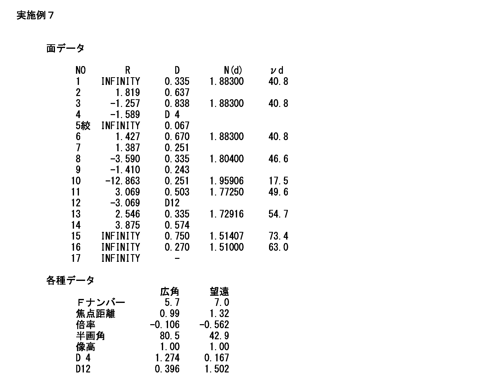
- Table 7 shows specific numerical configurations and specifications of optical components including the endoscope variable magnification optical system 100 according to the seventh embodiment.
- the group interval between the first lens group G1 and the second lens group G2 is indicated by a symbol “D4”
- the group interval between the second lens group G2 and the third lens group G3 is indicated by a symbol. This is indicated by “D12”.
- the variable power optical system 100 for endoscope according to the seventh embodiment has good optical performance and short power at each variable power position from the wide-angle end to the telephoto end.
- the configuration is suitable for a solid-state image sensor for exit pupil distance.
- Table 8 is a list of values calculated when the conditional expressions (1) to (7) are applied in each of the first to seventh embodiments.
- the endoscope variable power optical system 100 according to each of Examples 1, 2, 4 to 7 satisfies the conditional expressions (1) to (7) as shown in Table 8. Further, the endoscope variable magnification optical system 100 according to Example 3 satisfies the conditional expressions (1), (2), (4), and (6) as shown in Table 8. Thus, in each of the first to seventh embodiments, a further effect is achieved by satisfying each conditional expression.
- the embodiment of the present invention is not limited to the contents described above, and various modifications are possible within the scope of the technical idea of the present invention.
- the embodiment of the present application also includes an embodiment that is exemplarily specified in the specification or a combination of obvious embodiments and the like as appropriate.
Abstract
内視鏡用変倍光学系を、物体から順に、負のパワーを持つ第一のレンズ群、正のパワーを持つ第二のレンズ群、物体側に凸面を向けたメニスカスレンズを持つ第三のレンズ群からなる構成とし、第一のレンズ群の最も物体側のレンズ面から像面までの距離を一定に保ちながら、固定レンズ群である該第一のレンズ群及び第三のレンズ群に対して第二のレンズ群を光軸方向に移動させることで光学像を変倍させる構成とする。
Description
本発明は、内視鏡用変倍光学系及び内視鏡用変倍光学系を備える内視鏡に関する。
医療分野において、患者の体腔内を観察するための機器として、内視鏡(ファイバスコープ又は電子スコープ)が一般に知られ、実用に供されている。この種の内視鏡には、病変観察を精細に行うため、変倍機能を持つ変倍光学系を搭載したものがある。
例えば特許第3845331号公報(以下、「特許文献1」と記す。)に、内視鏡用変倍光学系の具体的構成が記載されている。特許文献1に記載の内視鏡用変倍光学系は、物体側から順に、負のパワーを持つ第一のレンズ群、正のパワーを持つ第二のレンズ群、正のパワーを持つ第三の3レンズ群、負のパワーを持つ第四のレンズ群からなり、第一のレンズ群から像面までの全長を変化させることなく、物体距離を変化させながら第二及び第三のレンズ群を移動させることにより、合焦状態を保持したまま全系の焦点距離を変化させることが可能な構成となっている。
近年、電子スコープ等の電子機器に搭載される固体撮像素子は、小型化の要請に応えるべく短い射出瞳距離に適した構成となっている。一方、特許文献1に記載の内視鏡用変倍光学系は、第三のレンズ群から射出された光線が第四のレンズ群(メニスカスレンズ)の物体側面(凹面)の光線高さが比較的低い位置に入射され、像側面(凸面)の光線高さが比較的高い位置で強い正のパワーで屈折されることから、射出瞳距離が長くなっている。そのため、特許文献1に記載の内視鏡用変倍光学系と短い射出瞳距離に適した構成の固体撮像素子とを組み合わせると、固体撮像素子の周辺画素に角度の浅い光線(テレセントリックに近い状態の光線)が入射されるため、周辺画素において被写体からの光が効率良く取り込まれないという問題が指摘される。
本発明は上記の事情に鑑みてなされたものであり、その目的とするところは、短射出瞳距離向けの固体撮像素子に適した内視鏡用変倍光学系及び該内視鏡用変倍光学系を備える内視鏡を提供することである。
本発明の一実施形態に係る内視鏡用変倍光学系は、物体から順に、負のパワーを持つ第一のレンズ群、正のパワーを持つ第二のレンズ群、物体側に凸面を向けたメニスカスレンズを持つ第三のレンズ群からなり、第一のレンズ群の最も物体側のレンズ面から像面までの距離を一定に保ちながら、固定レンズ群である該第一のレンズ群及び第三のレンズ群に対して第二のレンズ群を光軸方向に移動させることで光学像を変倍させる構成となっている。
また、本発明の一実施形態に係る内視鏡用変倍光学系は、望遠端での第二のレンズ群の倍率をm2tと定義し、広角端での該第二のレンズ群の倍率をm2wと定義した場合に、次の条件式
-1<m2t<m2w<-0.35
を満たす構成としてもよい。
-1<m2t<m2w<-0.35
を満たす構成としてもよい。
また、本発明の一実施形態に係る内視鏡用変倍光学系は、第三のレンズ群の焦点距離をf3(単位:mm)と定義し、広角端での第一から該第三のレンズ群の合成焦点距離をfw(単位:mm)と定義した場合に、次の条件式
4<f3/fw<11
を満たす構成としてもよい。
4<f3/fw<11
を満たす構成としてもよい。
また、本発明の一実施形態に係る内視鏡用変倍光学系は、
次の条件式
6<f3/fw<10
を満たす構成としてもよい。
次の条件式
6<f3/fw<10
を満たす構成としてもよい。
また、本発明の一実施形態において、第一のレンズ群は、例えば、負のパワーを持つ2つのレンズ、正のパワーを持つレンズからなる。
また、本発明の一実施形態に係る内視鏡用変倍光学系は、第二のレンズ群の焦点距離をf2(単位:mm)と定義し、第三のレンズ群の焦点距離をf3(単位:mm)と定義した場合に、次の条件式
0.2<f2/f3<0.7
を満たす構成としてもよい。
0.2<f2/f3<0.7
を満たす構成としてもよい。
また、本発明の一実施形態に係る内視鏡用変倍光学系は、次の条件式
0.2<f2/f3<0.4
を満たす構成としてもよい。
0.2<f2/f3<0.4
を満たす構成としてもよい。
また、本発明の一実施形態に係る内視鏡用変倍光学系は、第一のレンズ群の焦点距離をf1(単位:mm)と定義し、第三のレンズ群の焦点距離をf3(単位:mm)と定義した場合に、次の条件式
0.7<|f3/f1|<3.5
を満たす構成としてもよい。
0.7<|f3/f1|<3.5
を満たす構成としてもよい。
また、本発明の一実施形態に係る内視鏡用変倍光学系は、次の条件式
1.2<|f3/f1|<3.2
を満たす構成としてもよい。
1.2<|f3/f1|<3.2
を満たす構成としてもよい。
また、本発明の一実施形態に係る内視鏡用変倍光学系は、第一と第二のレンズ群との間に光軸上を該第二のレンズ群と一体に移動する絞りを有する構成としてもよい。
また、本発明の一実施形態に係る内視鏡は、上記の内視鏡用変倍光学系が先端に組み込まれた機器である。
本発明の一実施形態によれば、短射出瞳距離向けの固体撮像素子に適した内視鏡用変倍光学系及び該内視鏡用変倍光学系を備える内視鏡が提供される。
以下、図面を参照して、本発明の一実施形態に係る内視鏡用変倍光学系、及び該内視鏡用変倍光学系が組み込まれた電子スコープについて説明する。
図1は、本発明の一実施形態に係る電子スコープ1の外観を示す外観図である。図1に示されるように、電子スコープ1は、可撓性を有するシース11aによって外装された挿入部可撓管11を備えている。挿入部可撓管11の先端部分(湾曲部14)は、挿入部可撓管11の基端に連結された手元操作部13からの遠隔操作(具体的には、湾曲操作ノブ13aの回転操作)に応じて湾曲する。湾曲機構は、一般的な内視鏡に組み込まれている周知の機構であり、湾曲操作ノブ13aの回転操作に連動した操作ワイヤの牽引によって湾曲部14を湾曲させる。湾曲部14の先端には、硬質性を有する樹脂製筐体によって外装された先端部12の基端が連結している。先端部12の方向が湾曲操作ノブ13aの回転操作による湾曲動作に応じて変わることにより、電子スコープ1による撮影領域が移動する。
先端部12の樹脂製筐体の内部には、内視鏡用変倍光学系100(図1中斜線で示されたブロック)が組み込まれている。内視鏡用変倍光学系100は、撮影領域中の被写体の画像データを採取するため、被写体からの光を固体撮像素子(図示省略)の受光面上に結像させる。固体撮像素子としては、例えば、CCD(Charge Coupled Device)イメージセンサやCMOS(Complementary Metal Oxide Semiconductor)イメージセンサが挙げられる。
図2は、本発明の実施例1(詳しくは後述)に係る内視鏡用変倍光学系100及びその後段に配置された光学部品の配置を示す断面図である。図2(a)、図2(b)は、それぞれ、変倍位置が広角端、望遠端にあるときのレンズ配置を示す断面図である。次においては、図2を援用して、本発明の一実施形態に係る内視鏡用変倍光学系100について詳細な説明を行う。
内視鏡用変倍光学系100は、図2に示されるように、物体(被写体)側から順に、負のパワーを持つ第一のレンズ群G1、絞りS、正のパワーを持つ第二のレンズ群G2、第三のレンズ群G3を有している。内視鏡用変倍光学系100は、第一のレンズ群G1の最も物体側のレンズ面から像面までの距離(すなわち、内視鏡用変倍光学系100の全長)を一定に保ちながら、固定レンズ群である第一のレンズ群G1及び第三のレンズ群G3に対して第二のレンズ群G2を光軸方向AXに移動させることで、合焦状態を保持しつつ全系の焦点距離(第一のレンズ群G1から第三のレンズ群までの合成焦点距離)を変化させ、光学像を変倍させる構成となっている。内視鏡用変倍光学系100は、広角端の画角が120°以上(半画角が60°以上)となっている。各レンズ群G1~G3を構成する各光学レンズは、内視鏡用変倍光学系100の光軸AXを中心として回転対称な形状を有している。第三のレンズ群G3の後段には、固体撮像素子用の色補正フィルタFが配置されている。色補正フィルタFは、固体撮像素子を保護するカバーガラスCGに接着されている。
第一のレンズ群G1は、絞りSよりも物体側に配置された負のパワーを持つレンズ群である。図2の例では、第一のレンズ群G1は、物体側から順に、負のパワーを持つレンズL1、負のパワーを持つレンズL2、正のパワーを持つレンズL3を少なくとも有している。「少なくとも有している」と記載したのは、本発明の技術的思想の範囲において、平行平板等の別の光学素子を追加配置する構成例もあり得るからである。第二のレンズ群G2、第三のレンズ群G3の説明においても、同様の理由で「少なくとも有している」と表現している。このように、第一のレンズ群G1を、群内での負のパワーを分散し且つ正のパワーを持つ構成としたことにより、群としてコマ収差及び色収差の発生が良好に抑えられる。これにより、全系での収差変動が抑えられて、広角端から望遠端に亘って良好な収差性能が維持される。
なお、図2(a)の例では、第一のレンズ群G1は全体として3枚構成となっているが、別の例では2枚構成もあり得る(例えば後述の実施例6、7)。また、レンズL2とレンズL3は、接合レンズとして構成されてもよい(例えば後述の実施例5)。
第二のレンズ群G2は、絞りSの直後に配置された正のパワーを持つレンズ群である。図2の例では、第二のレンズ群G2は、物体側から順に、レンズL4、L5、接合レンズCL1を少なくとも有している。接合レンズCL1は、色収差の変化を抑えるため、正負2枚のレンズ(レンズL6、L7)を接合したものである。図2の例では、接合レンズCL1は、負レンズ(レンズL5)が物体側に配置され、正レンズ(レンズL6)が像側に配置されているが、別の実施形態では、正レンズが物体側に配置され、負レンズが像側に配置されてもよい。
第二のレンズ群G2は、固体撮像素子の受光面上に結像される光学像を変倍するため、絞りSと一体に光軸AX方向に移動する。第二のレンズ群G2と絞りSとを一体に移動させることにより、望遠端にしたときの非点収差の発生が効果的に抑えられる。なお、図2(a)の例では、第二のレンズ群G2は全体として4枚構成となっているが、別の例では3枚構成もあり得る(例えば後述の実施例3)。また、第二のレンズ群G2は、2つの接合レンズで構成されてもよい(例えば後述の実施例4)。
絞りSは、光軸AXを中心とした所定の円形開口を有する板状部材、又は第二のレンズ群G2の絞りSに最も近いレンズ面(図2の構成例においては、レンズL4の物体側面r8)であって光軸AXを中心とした所定の円形領域以外にコーティングされた遮光膜である。絞りSの厚みは、内視鏡用変倍光学系100を構成する各光学レンズの厚みと比べて非常に薄く、内視鏡用変倍光学系100の光学性能を計算する上で無視しても差し支えない。そのため、本明細書においては、絞りSの厚みをゼロとみなして説明を進める。
第三のレンズ群G3は、物体側に凸面を向けた正のパワーを持つメニスカスレンズ(レンズL8)を少なくとも有している。
このように、物体側に凸面を向けた正のパワーを持つメニスカスレンズ(レンズL8)を第二のレンズ群G2の像側に配置することにより、全系の焦点距離への影響を抑えつつ像面湾曲(非点収差)を低減させることができる。また、このように配置されたこのレンズL8を、小型化のために負のパワーが強められた設計の第一のレンズ群G1と組み合わせることで、ペッツバール和がゼロに近付く。
また、一般に、正のパワーを持つ可動レンズ群を望遠端側に移動させると、メリディオナル像面がサジタル像面よりもアンダーとなって、非点収差が発生する。しかし、図2の例では、物体側に凸面を向けた正のパワーを持つメニスカスレンズ(レンズL8)を可動レンズ群(第二のレンズ群G2)の像側に配置することにより、第二のレンズ群G2を望遠端側に移動させたときにレンズ8を通過する周辺光線が非点収差の補正に寄与する。
例えば、可動レンズ群の像側に最終レンズとして物体側に凹面を向けたメニスカスレンズを配置する構成を考える。この構成では、可動レンズから射出された光線が凹面(メニスカスレンズの物体側面)の光線高さが比較的低い位置に入射され、凸面(メニスカスレンズの像側面)の光線高さが比較的高い位置で強い正のパワーで屈折される。そのため、メリディオナル像面がアンダーとなると共に射出瞳距離が長くなり、固体撮像素子の周辺画素に角度の浅い光線(テレセントリックに近い状態の光線)が入射される。固体撮像素子が短射出瞳距離向けである場合、周辺画素において被写体からの光が効率良く取り込まれない。
これに対し、図2の例では、内視鏡用変倍光学系100の最終レンズ面(レンズL8の像側面)を凹面とすることにより、最終レンズ面を凸面とした場合と比べて、固体撮像素子の周辺画素への光線の入射角度を大きくすることができる。そのため、固体撮像素子が短射出瞳距離向けである場合、周辺画素において被写体からの光が効率良く取り込まれる。また、内視鏡用変倍光学系100と固体撮像素子間の短射出瞳距離化が好適に達成されるため、電子スコープ1の先端部12の全長を短くすることができる。
また、図2の例では、第三のレンズ群G3として物体側に凸面を向けたメニスカスレンズ(レンズL8)を配置することにより、第二のレンズ群G2から射出された光線がレンズL8の凸面の光線高さが比較的高い位置に入射される。そのため、第一のレンズ群G1及び第二のレンズ群G2において光線を大きく屈折させる必要がなく、第一のレンズ群G1及び第二のレンズ群G2のパワーが抑えられる。言い換えると、第一のレンズ群G1及び第二のレンズ群G2の誤差感度が低くなり、歩留まりの向上に寄与する。
内視鏡用変倍光学系100は、望遠端での第二のレンズ群G2の倍率をm2tと定義し、広角端での第二のレンズ群G2の倍率をm2wと定義した場合に、次の条件式(1)
-1<m2t<m2w<-0.35・・・(1)
を満たす構成となっている。
-1<m2t<m2w<-0.35・・・(1)
を満たす構成となっている。
条件式(1)が満たされることにより、内視鏡用変倍光学系100を精細なフォーカス調整に適した構成でありつつも小型化に設計することが可能となる。
条件式(1)において倍率m2wが右辺の値以上となる場合、広角端での第二のレンズ群G2の倍率m2wが低いことから、変倍に必要な第二のレンズ群G2の移動量が大きくなり、内視鏡用変倍光学系100の全長が長くなる。この結果、全長の長い内視鏡用変倍光学系100を収容する必要上、硬質部分である電子スコープ1の先端部12の全長を長くしなければならない。また、条件式(1)において倍率m2wが右辺の値以上となる場合、望遠端での第二のレンズ群G2の倍率m2tが相対的に大きくなることから、第二のレンズ群G2を移動させたときの最良物体距離の変化が大きくなる。そのため、精細なフォーカス調整ができなくなる。
体腔内を観察する際の電子スコープ1の使い勝手を考慮すると、最良物体距離は、広角端から望遠端に近付くほど短くなり、望遠端に到達したときに最も短くなるのが好ましい。しかし、条件式(1)において倍率m2tが左辺の値以下となる場合、最良物体距離が望遠端に到達する前に最も短くなってしまう。そのため、体腔内を観察する際の電子スコープ1の使い勝手が悪くなる。
内視鏡用変倍光学系100は、第三のレンズ群G3の焦点距離をf3(単位:mm)と定義し、広角端での全系の焦点距離をfw(単位:mm)と定義した場合に、次の条件式(2)
4<f3/fw<11・・・(2)
を満たす構成となっている。
4<f3/fw<11・・・(2)
を満たす構成となっている。
条件式(2)が満たされることにより、諸収差(主に、非点収差、色収差、コマ収差及び像面湾曲)が良好に補正されると共にシェーディングの発生が抑えられる。
条件式(2)において中辺の値が右辺の値以上となる場合、第三のレンズ群G3のパワーが弱くなりすぎることから、非点収差を良好に補正することが難しい。また、条件式(2)において中辺の値が右辺の値以上となる場合、第三のレンズ群G3が過度に大きいメニスカス形状を持つことにより、色収差及びコマ収差が増加してしまう。
条件式(2)において中辺の値が左辺の値以下となる場合、第三のレンズ群G3のパワーが強くなりすぎたり、第三のレンズ群G3の凸面の曲率に対し凹面の曲率が小さくなりすぎたりすることにより、ペッツバール和が増加して像面湾曲が大きく発生する。また、条件式(2)において中辺の値が左辺の値以下となる場合、固体撮像素子間への光の入射角度が小さくなりすぎることにより、シェーディングが発生して撮影画像が劣化する。
内視鏡用変倍光学系100は、更に、次の条件式(3)
6<f3/fw<10・・・(3)
を満たす構成としてもよい。これにより、諸収差(主に、非点収差、色収差、コマ収差及び像面湾曲)がより一層良好に補正されると共にシェーディングの発生がより一層抑えられる。
6<f3/fw<10・・・(3)
を満たす構成としてもよい。これにより、諸収差(主に、非点収差、色収差、コマ収差及び像面湾曲)がより一層良好に補正されると共にシェーディングの発生がより一層抑えられる。
内視鏡用変倍光学系100は、第二のレンズ群G2の焦点距離をf2(単位:mm)と定義した場合に、次の条件式(4)
0.2<f2/f3<0.7・・・(4)
を満たす構成となっている。
0.2<f2/f3<0.7・・・(4)
を満たす構成となっている。
条件式(4)が満たされることにより、内視鏡用変倍光学系100を精細なフォーカス調整に適した構成でありつつも小型化に設計することが可能となる。
条件式(4)において中辺の値が右辺の値以上となる場合、第二のレンズ群G2の負のパワーが相対的に弱くなりすぎることから、第二のレンズ群G2の移動量が大きくなるので、内視鏡用変倍光学系100の小型化に不利となる。また、条件式(4)において中辺の値が右辺の値以上となる場合、第三のレンズ群G3による光学像の縮小効果が強くなりすぎる。第三のレンズ群G3による光学像の縮小効果を相対的に弱めるため、第一のレンズ群G1及び第二のレンズ群G2の径を大きくしなければならない。
条件式(4)において中辺の値が左辺の値以下となる場合、第二のレンズ群G2の負のパワーが相対的に強くなり、第二のレンズ群G2の移動量が小さくなる。そのため、第二のレンズ群G2の僅かな移動でフォーカス調整を行わなければならない。そのため、精度の高いフォーカス調整機構が必要となり、電子スコープ1を高コスト化させたり大型化させたりしてしまう。また、条件式(4)において中辺の値が左辺の値以下となる場合、変倍位置が広角端、望遠端にあるときの固体撮像素子への光の入射角の変化が大きくなる。そのため、固体撮像素子のシェーディング特性に適合するのが難しくなる。
内視鏡用変倍光学系100は、更に、次の条件式(5)
0.2<f2/f3<0.4・・・(5)
を満たす構成としてもよい。これにより、内視鏡用変倍光学系100が精細なフォーカス調整により一層適した構成でありつつもより一層小型化に設計可能となる。
0.2<f2/f3<0.4・・・(5)
を満たす構成としてもよい。これにより、内視鏡用変倍光学系100が精細なフォーカス調整により一層適した構成でありつつもより一層小型化に設計可能となる。
内視鏡用変倍光学系100は、第一のレンズ群G1の焦点距離をf1(単位:mm)と定義した場合に、次の条件式(6)
0.7<|f3/f1|<3.5・・・(6)
を満たす構成となっている。
0.7<|f3/f1|<3.5・・・(6)
を満たす構成となっている。
条件式(6)が満たされることにより、諸収差(主に、非点収差及び像面湾曲)が良好に補正される構成でありつつも小型化に設計することが可能となる。
条件式(6)において中辺の値が右辺の値以上となる場合、第一のレンズ群G1のパワーが強くなりすぎてしまうため、ペッツバール和が負に増加して、第三のレンズ群G3で補正できないほど非点収差及び像面湾曲が大きく発生する。
条件式(6)において中辺の値が左辺の値以下となる場合、第一のレンズ群G1のパワーが弱くなりすぎてしまうため、第一のレンズ群G1の径を大きくしなければならない。また、条件式(6)において中辺の値が左辺の値以下となる場合、第三のレンズ群G3のパワーが強くなりすぎることから、コマ収差の発生が増加すると共に、変倍位置が広角端、望遠端にあるときの固体撮像素子への光の入射角の変化が大きくなる。そのため、固体撮像素子のシェーディング特性に適合するのが難しくなる。
内視鏡用変倍光学系100は、更に、次の条件式(7)
1.2<|f3/f1|<3.2・・・(7)
を満たす構成としてもよい。これにより、諸収差(主に、非点収差及び像面湾曲)がより一層良好に補正される構成でありつつもより一層小型化に設計することが可能となる。
1.2<|f3/f1|<3.2・・・(7)
を満たす構成としてもよい。これにより、諸収差(主に、非点収差及び像面湾曲)がより一層良好に補正される構成でありつつもより一層小型化に設計することが可能となる。
次に、これまで説明した内視鏡用変倍光学系100の具体的数値実施例を7例説明する。各数値実施例1~7に係る内視鏡用変倍光学系100は、図1に示される電子スコープ1の先端部12に配置されている。
上述したように、本発明の実施例1に係る内視鏡用変倍光学系100の構成は、図2に示される通りである。
本実施例1に係る内視鏡用変倍光学系100(及びその後段に配置された光学部品)の具体的数値構成(設計値)は、表1に示される。表1の上欄(面データ)に示される面番号NOは、絞りSに対応する面番号7を除き、図2中の面符号rn(nは自然数)に対応する。表1の上欄において、R(単位:mm)は光学部材の各面の曲率半径を、D(単位:mm)は光軸AX上の光学部材厚又は光学部材間隔を、N(d)はd線(波長588nm)の屈折率を、νdはd線のアッベ数を、それぞれ示す。
表1の下欄(各種データ)は、本実施例1に係る内視鏡用変倍光学系100の仕様(実効Fナンバー、全系の焦点距離(単位:mm)、光学倍率、半画角(単位:degree)、像高(単位:mm)、群間隔D6(単位:mm)、群間隔D14(単位:mm))を広角端、望遠端のそれぞれについて示す。群間隔D6は、第一のレンズ群G1と第二のレンズ群G2との群間隔である。群間隔D14は、第二のレンズ群G2と第三のレンズ群G3との群間隔である。群間隔D6、群間隔D14は、変倍位置に応じて変わる。

図3(a)のグラフA~Dは、本実施例1に係る内視鏡用変倍光学系100において変倍位置が広角端にあるときの各種収差図である。図3(b)のグラフA~Dは、本実施例1に係る内視鏡用変倍光学系100において変倍位置が望遠端にあるときの各種収差図である。図3(a)、(b)のグラフAは、d線、g線(波長436nm)、C線(波長656nm)での球面収差及び軸上色収差を示す。図3(a)、(b)のグラフBは、d線、g線、C線での倍率色収差を示す。グラフA、B中、実線はd線での収差を、点線はg線での収差を、一点鎖線はC線での収差を、それぞれ示す。図3(a)、(b)のグラフCは、非点収差を示す。グラフC中、実線はサジタル成分を、点線はメリディオナル成分を、それぞれ示す。図3(a)、(b)のグラフDは、歪曲収差を示す。グラフA~Cの縦軸は像高を、横軸は収差量を、それぞれ示す。グラフDの縦軸は像高を、横軸は歪曲率を、それぞれ示す。なお、本実施例1の各表又は各図面についての説明は、以降の各数値実施例で提示される各表又は各図面においても適用する。
本実施例1に係る内視鏡用変倍光学系100は、広角端、望遠端の何れにおいても諸収差が良好に補正されつつ(図3参照)、第三のレンズ群G3として物体側に凸面を向けたメニスカスレンズが配置されることにより(図2及び表1参照)、短射出瞳距離向けの固体撮像素子に適した構成となっている。なお、広角端と望遠端との中間域においては、図3(a)と図3(b)とが示す範囲内で各種収差が変化する。すなわち、本実施例1に係る内視鏡用変倍光学系100は、広角端から望遠端までの各変倍位置で光学性能が良好である。
図4(a)、(b)は、本実施例2に係る内視鏡用変倍光学系100を含む各光学部品の配置を示す断面図である。図4(a)は、変倍位置が広角端にあるときのレンズ配置を示す。図4(b)は、変倍位置が望遠端にあるときのレンズ配置を示す。
図5(a)のグラフA~Dは、本実施例2に係る内視鏡用変倍光学系100において変倍位置が広角端にあるときの各種収差図である。図5(b)のグラフA~Dは、本実施例2に係る内視鏡用変倍光学系100において変倍位置が望遠端にあるときの各種収差図である。
表2は、本実施例2に係る内視鏡用変倍光学系100を含む各光学部品の具体的数値構成及び仕様を示す。本実施例2に係る内視鏡用変倍光学系100は、図4及び図5並びに表2から判るように、広角端から望遠端までの各変倍位置で光学性能が良好であると共に短射出瞳距離向けの固体撮像素子に適した構成となっている。
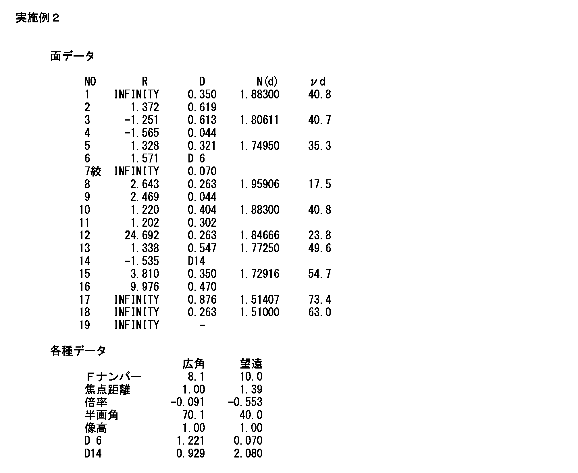
図6(a)、(b)は、本実施例3に係る内視鏡用変倍光学系100を含む各光学部品の配置を示す断面図である。図6(a)は、変倍位置が広角端にあるときのレンズ配置を示す。図6(b)は、変倍位置が望遠端にあるときのレンズ配置を示す。
図7(a)のグラフA~Dは、本実施例3に係る内視鏡用変倍光学系100において変倍位置が広角端にあるときの各種収差図である。図7(b)のグラフA~Dは、本実施例3に係る内視鏡用変倍光学系100において変倍位置が望遠端にあるときの各種収差図である。
表3は、本実施例3に係る内視鏡用変倍光学系100を含む各光学部品の具体的数値構成及び仕様を示す。なお、表3では、第二のレンズ群G2と第三のレンズ群G3との群間隔を符号「D12」で示す。本実施例3に係る内視鏡用変倍光学系100は、図6及び図7並びに表3から判るように、広角端から望遠端までの各変倍位置で光学性能が良好であると共に短射出瞳距離向けの固体撮像素子に適した構成となっている。
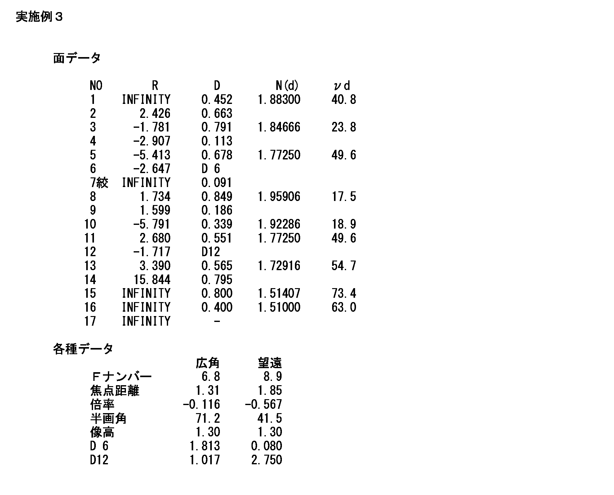
図8(a)、(b)は、本実施例4に係る内視鏡用変倍光学系100を含む各光学部品の配置を示す断面図である。図8(a)は、変倍位置が広角端にあるときのレンズ配置を示す。図8(b)は、変倍位置が望遠端にあるときのレンズ配置を示す。
図9(a)のグラフA~Dは、本実施例4に係る内視鏡用変倍光学系100において変倍位置が広角端にあるときの各種収差図である。図9(b)のグラフA~Dは、本実施例4に係る内視鏡用変倍光学系100において変倍位置が望遠端にあるときの各種収差図である。
表4は、本実施例4に係る内視鏡用変倍光学系100を含む各光学部品の具体的数値構成及び仕様を示す。なお、表4では、第二のレンズ群G2と第三のレンズ群G3との群間隔を符号「D13」で示す。本実施例4に係る内視鏡用変倍光学系100は、図8及び図9並びに表4から判るように、広角端から望遠端までの各変倍位置で光学性能が良好であると共に短射出瞳距離向けの固体撮像素子に適した構成となっている。
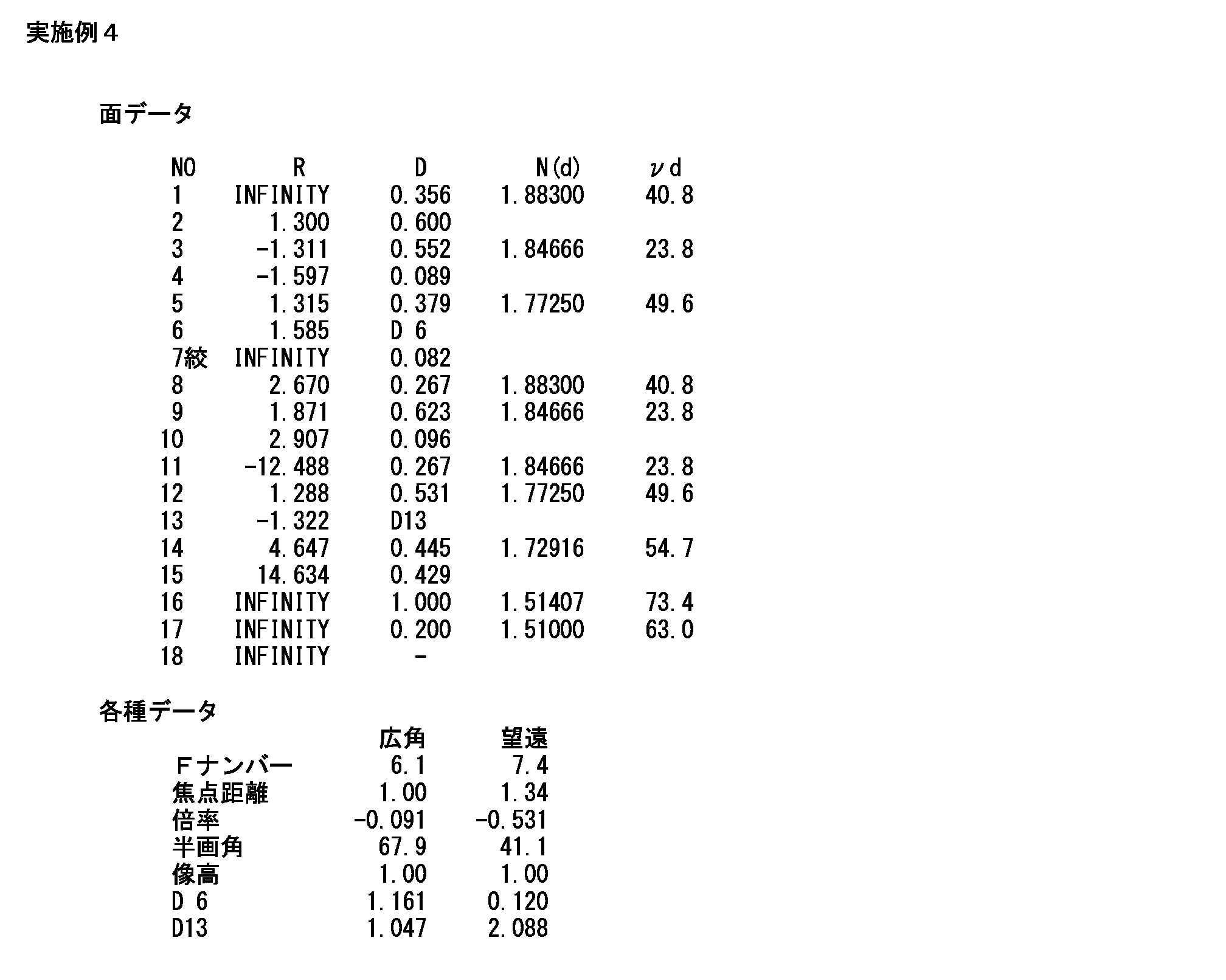
図10(a)、(b)は、本実施例5に係る内視鏡用変倍光学系100を含む各光学部品の配置を示す断面図である。図10(a)は、変倍位置が広角端にあるときのレンズ配置を示す。図10(b)は、変倍位置が望遠端にあるときのレンズ配置を示す。
図11(a)のグラフA~Dは、本実施例5に係る内視鏡用変倍光学系100において変倍位置が広角端にあるときの各種収差図である。図11(b)のグラフA~Dは、本実施例5に係る内視鏡用変倍光学系100において変倍位置が望遠端にあるときの各種収差図である。
表5は、本実施例5に係る内視鏡用変倍光学系100を含む各光学部品の具体的数値構成及び仕様を示す。なお、表5では、第一のレンズ群G1と第二のレンズ群G2との群間隔を符号「D5」で示し、第二のレンズ群G2と第三のレンズ群G3との群間隔を符号「D13」で示す。本実施例5に係る内視鏡用変倍光学系100は、図10及び図11並びに表5から判るように、広角端から望遠端までの各変倍位置で光学性能が良好であると共に短射出瞳距離向けの固体撮像素子に適した構成となっている。

図12(a)、(b)は、本実施例6に係る内視鏡用変倍光学系100を含む各光学部品の配置を示す断面図である。図12(a)は、変倍位置が広角端にあるときのレンズ配置を示す。図12(b)は、変倍位置が望遠端にあるときのレンズ配置を示す。
図13(a)のグラフA~Dは、本実施例6に係る内視鏡用変倍光学系100において変倍位置が広角端にあるときの各種収差図である。図13(b)のグラフA~Dは、本実施例6に係る内視鏡用変倍光学系100において変倍位置が望遠端にあるときの各種収差図である。
表6は、本実施例6に係る内視鏡用変倍光学系100を含む各光学部品の具体的数値構成及び仕様を示す。なお、表6では、第一のレンズ群G1と第二のレンズ群G2との群間隔を符号「D4」で示し、第二のレンズ群G2と第三のレンズ群G3との群間隔を符号「D12」で示す。本実施例6に係る内視鏡用変倍光学系100は、図12及び図13並びに表6から判るように、広角端から望遠端までの各変倍位置で光学性能が良好であると共に短射出瞳距離向けの固体撮像素子に適した構成となっている。
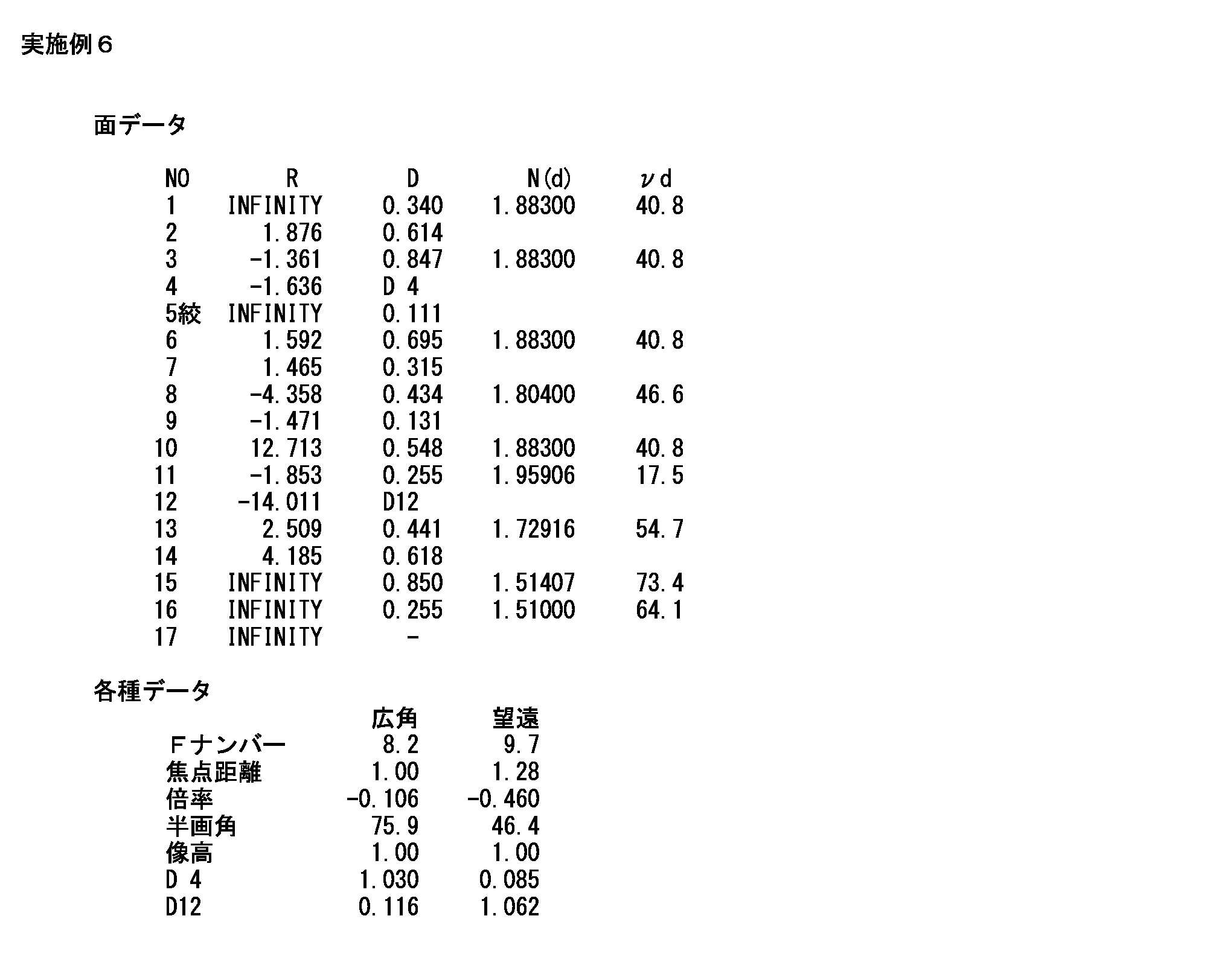
図14(a)、(b)は、本実施例7に係る内視鏡用変倍光学系100を含む各光学部品の配置を示す断面図である。図14(a)は、変倍位置が広角端にあるときのレンズ配置を示す。図14(b)は、変倍位置が望遠端にあるときのレンズ配置を示す。
図15(a)のグラフA~Dは、本実施例7に係る内視鏡用変倍光学系100において変倍位置が広角端にあるときの各種収差図である。図15(b)のグラフA~Dは、本実施例7に係る内視鏡用変倍光学系100において変倍位置が望遠端にあるときの各種収差図である。
表7は、本実施例7に係る内視鏡用変倍光学系100を含む各光学部品の具体的数値構成及び仕様を示す。なお、表7では、第一のレンズ群G1と第二のレンズ群G2との群間隔を符号「D4」で示し、第二のレンズ群G2と第三のレンズ群G3との群間隔を符号「D12」で示す。本実施例7に係る内視鏡用変倍光学系100は、図14及び図15並びに表7から判るように、広角端から望遠端までの各変倍位置で光学性能が良好であると共に短射出瞳距離向けの固体撮像素子に適した構成となっている。
(条件式検証)
表8は、本実施例1~7の各実施例において、条件式(1)~(7)の各条件式を適用したときに算出される値の一覧表である。
表8は、本実施例1~7の各実施例において、条件式(1)~(7)の各条件式を適用したときに算出される値の一覧表である。
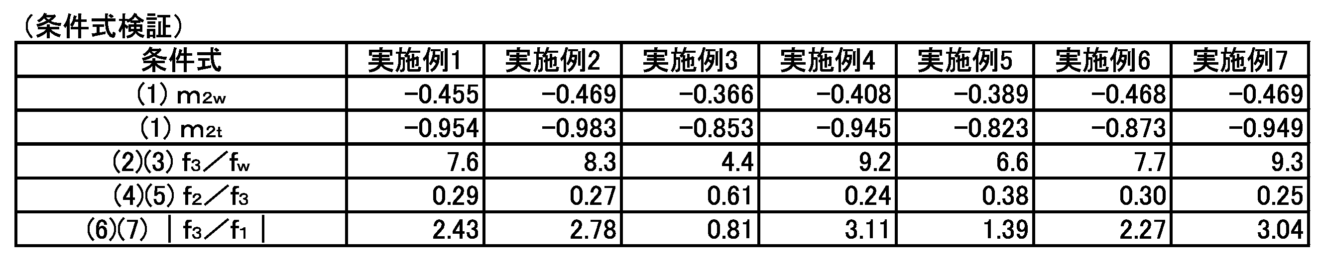
本実施例1、2、4~7の各実施例に係る内視鏡用変倍光学系100は、表8に示されるように、条件式(1)~(7)を満たす。また、本実施例3に係る内視鏡用変倍光学系100は、表8に示されるように、条件式(1)、(2)、(4)及び(6)を満たす。これにより、本実施例1~7の各実施例では、各条件式を満たすことによる更なる効果が奏される。
以上が本発明の例示的な実施形態の説明である。本発明の実施形態は、上記に説明した内容に限定されず、本発明の技術的思想の範囲において様々な変形が可能である。例えば明細書中に例示的に明示される実施形態等又は自明な実施形態等を適宜組み合わせた内容も本願の実施形態に含まれる。
Claims (11)
- 物体から順に、負のパワーを持つ第一のレンズ群、正のパワーを持つ第二のレンズ群、物体側に凸面を向けたメニスカスレンズを持つ第三のレンズ群からなり、
前記第一のレンズ群の最も物体側のレンズ面から像面までの距離を一定に保ちながら、固定レンズ群である該第一のレンズ群及び前記第三のレンズ群に対して前記第二のレンズ群を光軸方向に移動させることで光学像を変倍させる、
内視鏡用変倍光学系。 - 望遠端での前記第二のレンズ群の倍率をm2tと定義し、広角端での該第二のレンズ群の倍率をm2wと定義した場合に、次の条件式
-1<m2t<m2w<-0.35
を満たす、
請求項1に記載の内視鏡用変倍光学系。 - 前記第三のレンズ群の焦点距離をf3(単位:mm)と定義し、広角端での前記第一から該第三のレンズ群の合成焦点距離をfw(単位:mm)と定義した場合に、次の条件式
4<f3/fw<11
を満たす、
請求項1又は請求項2に記載の内視鏡用変倍光学系。 - 次の条件式
6<f3/fw<10
を満たす、
請求項3に記載の内視鏡用変倍光学系。 - 前記第一のレンズ群は、
負のパワーを持つ2つのレンズ、正のパワーを持つレンズからなる、
請求項1から請求項4の何れか一項に記載の内視鏡用変倍光学系。 - 前記第二のレンズ群の焦点距離をf2(単位:mm)と定義し、前記第三のレンズ群の焦点距離をf3(単位:mm)と定義した場合に、次の条件式
0.2<f2/f3<0.7
を満たす、
請求項1から請求項5の何れか一項に記載の内視鏡用変倍光学系。 - 次の条件式
0.2<f2/f3<0.4
を満たす、
請求項6に記載の内視鏡用変倍光学系。 - 前記第一のレンズ群の焦点距離をf1(単位:mm)と定義し、前記第三のレンズ群の焦点距離をf3(単位:mm)と定義した場合に、次の条件式
0.7<|f3/f1|<3.5
を満たす、
請求項1から請求項7の何れか一項に記載の内視鏡用変倍光学系。 - 次の条件式
1.2<|f3/f1|<3.2
を満たす、
請求項8に記載の内視鏡用変倍光学系。 - 前記第一と前記第二のレンズ群との間に光軸上を該第二のレンズ群と一体に移動する絞りを有する、
請求項1から請求項9の何れか一項に記載の内視鏡用変倍光学系。 - 請求項1から請求項10の何れか一項に記載の内視鏡用変倍光学系が先端に組み込まれた、
内視鏡。
Priority Applications (6)
| Application Number | Priority Date | Filing Date | Title |
|---|---|---|---|
| PCT/JP2016/055251 WO2017145265A1 (ja) | 2016-02-23 | 2016-02-23 | 内視鏡用変倍光学系及び内視鏡 |
| PCT/JP2017/006296 WO2017146021A1 (ja) | 2016-02-23 | 2017-02-21 | 内視鏡用変倍光学系、内視鏡及び内視鏡システム |
| CN201790000092.0U CN207586523U (zh) | 2016-02-23 | 2017-02-21 | 内窥镜用变焦光学系统、内窥镜以及内窥镜系统 |
| DE112017000944.8T DE112017000944B4 (de) | 2016-02-23 | 2017-02-21 | Endoskop-Vergrößerungsoptik, Endoskop und ein Endoskopsystem |
| US16/077,909 US10898061B2 (en) | 2016-02-23 | 2017-02-21 | Endoscope magnification optical system, endoscope, and endoscope system |
| JP2018501691A JP6636128B2 (ja) | 2016-02-23 | 2017-02-21 | 内視鏡用変倍光学系、内視鏡及び内視鏡システム |
Applications Claiming Priority (1)
| Application Number | Priority Date | Filing Date | Title |
|---|---|---|---|
| PCT/JP2016/055251 WO2017145265A1 (ja) | 2016-02-23 | 2016-02-23 | 内視鏡用変倍光学系及び内視鏡 |
Publications (1)
| Publication Number | Publication Date |
|---|---|
| WO2017145265A1 true WO2017145265A1 (ja) | 2017-08-31 |
Family
ID=59684808
Family Applications (2)
| Application Number | Title | Priority Date | Filing Date |
|---|---|---|---|
| PCT/JP2016/055251 WO2017145265A1 (ja) | 2016-02-23 | 2016-02-23 | 内視鏡用変倍光学系及び内視鏡 |
| PCT/JP2017/006296 WO2017146021A1 (ja) | 2016-02-23 | 2017-02-21 | 内視鏡用変倍光学系、内視鏡及び内視鏡システム |
Family Applications After (1)
| Application Number | Title | Priority Date | Filing Date |
|---|---|---|---|
| PCT/JP2017/006296 WO2017146021A1 (ja) | 2016-02-23 | 2017-02-21 | 内視鏡用変倍光学系、内視鏡及び内視鏡システム |
Country Status (5)
| Country | Link |
|---|---|
| US (1) | US10898061B2 (ja) |
| JP (1) | JP6636128B2 (ja) |
| CN (1) | CN207586523U (ja) |
| DE (1) | DE112017000944B4 (ja) |
| WO (2) | WO2017145265A1 (ja) |
Cited By (1)
| Publication number | Priority date | Publication date | Assignee | Title |
|---|---|---|---|---|
| JPWO2017145208A1 (ja) * | 2016-02-24 | 2018-08-16 | パナソニックIpマネジメント株式会社 | ズームレンズ系、ズームレンズ系を有する撮像装置及び撮像装置を有する車両 |
Families Citing this family (14)
| Publication number | Priority date | Publication date | Assignee | Title |
|---|---|---|---|---|
| WO2018116865A1 (ja) * | 2016-12-21 | 2018-06-28 | オリンパス株式会社 | 内視鏡用対物光学系 |
| DE102017107106A1 (de) | 2017-04-03 | 2018-10-04 | Hoya Corporation | Endoskop mit weitwinkeloptik und arbeitskanal |
| JP6861131B2 (ja) | 2017-09-12 | 2021-04-21 | Hoya株式会社 | 内視鏡用対物レンズユニット及び内視鏡 |
| JP2019049680A (ja) | 2017-09-12 | 2019-03-28 | Hoya株式会社 | 内視鏡用対物レンズユニット及び内視鏡 |
| US11194136B2 (en) | 2017-12-12 | 2021-12-07 | Nittoh Inc. | Optical system for image pickup and image pickup apparatus |
| JP6899030B2 (ja) * | 2018-03-22 | 2021-07-07 | オリンパス株式会社 | 対物光学系、撮像装置、内視鏡、及び内視鏡システム |
| JP7254271B2 (ja) * | 2019-01-28 | 2023-04-10 | 株式会社ニコン | 変倍光学系、光学機器 |
| CN112006639B (zh) * | 2019-05-31 | 2024-02-23 | 北京点阵虹光光电科技有限公司 | 电子内窥镜成像镜头 |
| CN112213846B (zh) * | 2019-07-09 | 2022-08-02 | Oppo广东移动通信有限公司 | 变焦镜头和电子装置 |
| CN110873950A (zh) * | 2019-11-29 | 2020-03-10 | 浙江大学 | 内窥镜物镜变焦光学系统 |
| CN111522081A (zh) * | 2020-05-26 | 2020-08-11 | 重庆金山科技(集团)有限公司 | 一种液体透镜、变焦内窥镜物镜、内窥镜及变焦方法 |
| CN112731638B (zh) * | 2020-12-31 | 2022-08-16 | 上海澳华内镜股份有限公司 | 一种内窥镜光学系统 |
| CN113341550B (zh) * | 2021-07-29 | 2021-11-09 | 成都极米科技股份有限公司 | 一种应用于投影的变焦镜头 |
| CN115268039B (zh) * | 2022-09-28 | 2023-02-03 | 江西联创电子有限公司 | 光学镜头 |
Citations (7)
| Publication number | Priority date | Publication date | Assignee | Title |
|---|---|---|---|---|
| JPS6424214A (en) * | 1987-07-20 | 1989-01-26 | Canon Kk | Variable power optical system |
| JPH05323190A (ja) * | 1992-05-18 | 1993-12-07 | Fuji Photo Optical Co Ltd | 小型ズームレンズ |
| JPH1048519A (ja) * | 1996-08-01 | 1998-02-20 | Asahi Optical Co Ltd | 変倍光学系 |
| JP2007093961A (ja) * | 2005-09-28 | 2007-04-12 | Fujinon Corp | 2焦点切替型結像レンズ |
| JP2010032567A (ja) * | 2008-07-24 | 2010-02-12 | Fujinon Corp | 投写型可変焦点レンズおよび投写型表示装置 |
| WO2010119640A1 (ja) * | 2009-04-16 | 2010-10-21 | オリンパスメディカルシステムズ株式会社 | 対物光学系 |
| WO2014129089A1 (ja) * | 2013-02-22 | 2014-08-28 | オリンパスメディカルシステムズ株式会社 | 内視鏡用対物光学系及び撮像装置 |
Family Cites Families (9)
| Publication number | Priority date | Publication date | Assignee | Title |
|---|---|---|---|---|
| JP3845331B2 (ja) | 2002-04-05 | 2006-11-15 | ペンタックス株式会社 | 内視鏡対物光学系 |
| JP2005037576A (ja) | 2003-07-18 | 2005-02-10 | Minolta Co Ltd | 撮像レンズ装置 |
| JP2005292403A (ja) * | 2004-03-31 | 2005-10-20 | Konica Minolta Opto Inc | 変倍光学系、撮像レンズ装置及びデジタル機器 |
| TWI507727B (zh) * | 2013-04-30 | 2015-11-11 | Young Optics Inc | 變焦鏡頭 |
| JP5892985B2 (ja) * | 2013-09-27 | 2016-03-23 | 富士フイルム株式会社 | 内視鏡システム及びプロセッサ装置並びに作動方法 |
| JP6560984B2 (ja) * | 2013-12-11 | 2019-08-14 | オリンパス株式会社 | 変倍光学系及びそれを備えた撮像装置、撮像システム |
| CN107076967B (zh) | 2015-09-07 | 2020-09-01 | Hoya株式会社 | 内窥镜用变倍光学系统及内窥镜 |
| JPWO2017043351A1 (ja) | 2015-09-07 | 2018-06-21 | Hoya株式会社 | 内視鏡用変倍光学系、及び内視鏡 |
| CN107615129B (zh) | 2016-02-23 | 2019-09-13 | Hoya株式会社 | 内窥镜和用于该内窥镜的可变屈光度光学系统 |
-
2016
- 2016-02-23 WO PCT/JP2016/055251 patent/WO2017145265A1/ja active Application Filing
-
2017
- 2017-02-21 CN CN201790000092.0U patent/CN207586523U/zh active Active
- 2017-02-21 US US16/077,909 patent/US10898061B2/en active Active
- 2017-02-21 DE DE112017000944.8T patent/DE112017000944B4/de active Active
- 2017-02-21 WO PCT/JP2017/006296 patent/WO2017146021A1/ja active Application Filing
- 2017-02-21 JP JP2018501691A patent/JP6636128B2/ja active Active
Patent Citations (7)
| Publication number | Priority date | Publication date | Assignee | Title |
|---|---|---|---|---|
| JPS6424214A (en) * | 1987-07-20 | 1989-01-26 | Canon Kk | Variable power optical system |
| JPH05323190A (ja) * | 1992-05-18 | 1993-12-07 | Fuji Photo Optical Co Ltd | 小型ズームレンズ |
| JPH1048519A (ja) * | 1996-08-01 | 1998-02-20 | Asahi Optical Co Ltd | 変倍光学系 |
| JP2007093961A (ja) * | 2005-09-28 | 2007-04-12 | Fujinon Corp | 2焦点切替型結像レンズ |
| JP2010032567A (ja) * | 2008-07-24 | 2010-02-12 | Fujinon Corp | 投写型可変焦点レンズおよび投写型表示装置 |
| WO2010119640A1 (ja) * | 2009-04-16 | 2010-10-21 | オリンパスメディカルシステムズ株式会社 | 対物光学系 |
| WO2014129089A1 (ja) * | 2013-02-22 | 2014-08-28 | オリンパスメディカルシステムズ株式会社 | 内視鏡用対物光学系及び撮像装置 |
Cited By (2)
| Publication number | Priority date | Publication date | Assignee | Title |
|---|---|---|---|---|
| JPWO2017145208A1 (ja) * | 2016-02-24 | 2018-08-16 | パナソニックIpマネジメント株式会社 | ズームレンズ系、ズームレンズ系を有する撮像装置及び撮像装置を有する車両 |
| US10967794B2 (en) | 2016-02-24 | 2021-04-06 | Panasonic Intellectual Property Management Co., Ltd. | Zoom lens system, imaging device having zoom lens system, and vehicle having imaging device |
Also Published As
| Publication number | Publication date |
|---|---|
| DE112017000944T5 (de) | 2019-01-03 |
| JP6636128B2 (ja) | 2020-01-29 |
| US10898061B2 (en) | 2021-01-26 |
| DE112017000944B4 (de) | 2021-02-18 |
| JPWO2017146021A1 (ja) | 2018-12-13 |
| CN207586523U (zh) | 2018-07-06 |
| US20190053695A1 (en) | 2019-02-21 |
| WO2017146021A1 (ja) | 2017-08-31 |
Similar Documents
| Publication | Publication Date | Title |
|---|---|---|
| WO2017145265A1 (ja) | 内視鏡用変倍光学系及び内視鏡 | |
| CN107076967B (zh) | 内窥镜用变倍光学系统及内窥镜 | |
| JP6046322B1 (ja) | 内視鏡用変倍光学系及び内視鏡 | |
| JP5601924B2 (ja) | 内視鏡用変倍光学系、及び内視鏡 | |
| JP6195808B2 (ja) | 内視鏡用対物レンズおよび内視鏡 | |
| JP5653243B2 (ja) | 内視鏡用光学系、及び内視鏡 | |
| JP5567224B2 (ja) | 内視鏡用対物レンズおよび内視鏡 | |
| WO2017043351A1 (ja) | 内視鏡用変倍光学系、及び内視鏡 | |
| JP5567225B2 (ja) | 内視鏡用対物レンズおよび内視鏡 | |
| JP2019109356A (ja) | 内視鏡用対物光学系及び内視鏡 | |
| WO2018235352A1 (ja) | 内視鏡用対物光学系 | |
| JP6001229B2 (ja) | 内視鏡対物光学系 | |
| CN109557657B (zh) | 内窥镜用对物光学系统及内窥镜 | |
| CN107703606B (zh) | 内窥镜用物镜光学系统以及内窥镜 | |
| JP6754916B2 (ja) | 内視鏡用変倍光学系及び内視鏡 | |
| CN109557656B (zh) | 内窥镜用对物光学系统及内窥镜 | |
| WO2019159778A1 (ja) | 内視鏡用光学系及び内視鏡 |
Legal Events
| Date | Code | Title | Description |
|---|---|---|---|
| NENP | Non-entry into the national phase |
Ref country code: DE |
|
| 121 | Ep: the epo has been informed by wipo that ep was designated in this application |
Ref document number: 16891423 Country of ref document: EP Kind code of ref document: A1 |
|
| 122 | Ep: pct application non-entry in european phase |
Ref document number: 16891423 Country of ref document: EP Kind code of ref document: A1 |
|
| NENP | Non-entry into the national phase |
Ref country code: JP |