WO2017144981A1 - 易撕盖生产线 - Google Patents
易撕盖生产线 Download PDFInfo
- Publication number
- WO2017144981A1 WO2017144981A1 PCT/IB2017/050120 IB2017050120W WO2017144981A1 WO 2017144981 A1 WO2017144981 A1 WO 2017144981A1 IB 2017050120 W IB2017050120 W IB 2017050120W WO 2017144981 A1 WO2017144981 A1 WO 2017144981A1
- Authority
- WO
- WIPO (PCT)
- Prior art keywords
- cover
- film
- aluminum foil
- intermediate hole
- tear
- Prior art date
Links
Images


Classifications
-
- B—PERFORMING OPERATIONS; TRANSPORTING
- B21—MECHANICAL METAL-WORKING WITHOUT ESSENTIALLY REMOVING MATERIAL; PUNCHING METAL
- B21D—WORKING OR PROCESSING OF SHEET METAL OR METAL TUBES, RODS OR PROFILES WITHOUT ESSENTIALLY REMOVING MATERIAL; PUNCHING METAL
- B21D51/00—Making hollow objects
- B21D51/16—Making hollow objects characterised by the use of the objects
- B21D51/38—Making inlet or outlet arrangements of cans, tins, baths, bottles, or other vessels; Making can ends; Making closures
- B21D51/44—Making closures, e.g. caps
Definitions
- the utility model relates to an easy-to-tear cover production line which can realize high-speed manufacture and easy tearing cover, and can avoid friction damage of the cover, and has high authenticity rate.
- CN103459061B the name "manufacturing apparatus and method for tearing off a cover", comprising a conveyor for a cover element and a cover and a plurality of processing stations for the cover element and the cover arranged along the conveyor, the processing station comprising: a sealing station (5) constituting to seal a film portion (25) comprising a tear-off tab (29) to a cover member formed as a cover ring (20'); and a bending station (7)
- the tear-off tab (29) in the bending station can be bent towards the upper side of the film portion; characterized in that a gluing station (40) is provided between the sealing station and the bending station, the gluing station having means ( 41)
- the manufacturing method comprises the steps of: supplying a strip (35) for tearing off the film material; punching the film portion (25) with the tear-off tab (29) from the belt (35); and the film portion (25) Sealed on the cover ring (20'), and the tear-off tab (29) is bent back onto the cover, characterized by the following steps: the glue patch (30) separated from the glue tape is applied to the seal In one position on the film portion, the tear-off tab (29) that is bent back on the tear-off cover (28) is in this position.
- CN101947608 A the name "method and apparatus for manufacturing a peeling cover” wherein first a cover ring is provided, the cover ring having a flange edge and a sealing surface joined to its flange edge, wherein the sealing surface is further One end abuts the cover ring opening, and then seals the release foil to the sealing surface, wherein in order to tension the release foil after the sealing step, the sealing surface follows the flange A section of the ramp is clamped together with the stripping foil between the upper gripping tool and the lower gripping tool having a flat gripping surface, and the sealing surface is not gripped by the upper gripping tool by means of a pressing tool A section of the tool and the lower gripping tool is bent in a direction along the edge of the upper cover.
- a device comprising: a transfer device for a cover member and a cover; a sealing station formed to punch a foil segment from the sealing foil and sealing the sealable bottom side of the foil segment to the cover ring, wherein along The conveying direction is provided after the sealing station with a processing station, the processing station having a clamping tool, the clamping tool having a flat clamping surface by means of which a clamping tool can be clamped adjacent to the flange edge The surface is sealed and the processing station has a pressing tool by means of which the portion of the sealing edge that is not clamped by the clamping tool can be bent in the direction of the edge of the upper cover.
- the cover of the disclosed easy-to-tear device is carried by two motors, one of which drives the crank-link mechanism to drive the carrier to reciprocate, and the other motor Driving a horizontal long axis drives the up and down movement of the carrier, thereby realizing the lifting-forward-down-return-return of the cover.
- This type of handling is slow in production and cannot achieve high-speed production.
- CN105081128 A the name "a processing device and processing technology for easily tearing the cover", comprising a conveyor belt (1) for conveying the cover body (14), the conveyor belt (1) being sequentially provided with a cover body ( 14) a lid conveying unit (2) placed in turn on the conveyor belt (1), a lid processing unit for processing the lid body (14) on the conveyor belt (1), for use on the foil strip a cover film processing unit (7) punched out of the cover film and a cover film sealing unit for fixing the cover film on the cover body (14) on the conveyor belt (1), the conveyor belt (1) being evenly distributed There is a fixing member (12) for fixing the cover (14).
- a cover flip unit (6) is further disposed between the cover unit (14) processing unit and the cover film processing unit (7), and the cover flip unit (6) includes a disk-shaped flip disk (15). And a rotating shaft (16) fixed at the center of the turning disk (15), the rotating shaft (16) is horizontally disposed and perpendicular to the rotating disk (15), and the rotating plate (15) is uniformly opened with a plurality of strips Positioning groove (17), the positioning groove (17) is arranged to coincide with the diameter of the turning disk (15). The bottom of the positioning groove (17) is recessed toward the center of the turning disk (15).
- the cover film sealing unit comprises a pre-sealing device (8) and a main sealing device (9), the pre-sealing device (8) being located between the cover film processing unit (7) and the main sealing device (9).
- the cover film processing unit (7) and the pre-sealing device (8) are of a unitary structure.
- the cover conveying unit (2) The utility model comprises a transport rack, wherein the transport rack is fixed with a vertically arranged storage rack (20), and the storage rack (20) comprises at least three vertically arranged and annularly arranged limiting rods (18).
- the bottom of the storage rack (20) is provided with a dispensing device, and the distributing device comprises at least three separating cutters (19) which are evenly distributed at the bottom of the storage rack (20), the points
- the material knives (19) are in a flat cylindrical shape and are arranged vertically.
- the outer side of the separating knives (19) is provided with a thread groove and the hopper (19) partially protrudes into the hopper (20), all the materials are divided.
- the knives (19) are connected by a timing belt or a gear.
- Each of the four fixing members (12) on the conveyor belt (1) is a set for fixing the cover body (14), and the conveyor belt (1) comprises two belt bodies (11) arranged in parallel; Two of the four fixing members (12) in one set are located on one strip body (11), and the other two are located on the other strip body (11); the fixing member (12) has a support cover thereon a lifting portion (12a) at the bottom of the body (14) and for blocking the cover (14) Side blocking portion (12b).
- the easy-to-tear processing process sequentially completes the following steps on the same conveyor belt (1) for conveying the cover body (14): A, the cover body (14) is transported, and the cover body (14) is sequentially placed on the transport.
- the cover film is punched out; D, the cover film is sealed, and the cover film is sealed and fixed on the cover body (14).
- the step D includes the following steps: D1, pre-sealing, and step C on the same module unit simultaneously, directly pressing the stamped cover film on the cover body (14); D2, main seal, The cover film is sealed and fixed to the cover body (14).
- the cover handling mode is realized in the form of two sets of synchronous belts plus flipping plates in front and rear. Since the flipping disc is added in the middle (as shown in Fig. 5, 27 is a flipping disc in the figure), not only the structure of the flipping disc is complicated. The adjustment is very difficult, and the cover rubs into the flip disk slot to be easily scratched, and the scrap rate is high.
- One of the design purposes of the utility model avoids the deficiencies in the background art, and designs a high-speed manufacturing easy-to-tear cover, and can avoid friction damage of the cover, and has a high genuine rate.
- the second aspect of the present invention on the basis of the background art, by adding a magnetic separator on both sides of the cover frame in the cover lower cover device, the pressure of the bottom cover is reduced, and the cover screw is prevented from crushing the cover. And by adding a flipping cylinder, the entire cover and the lower cover mechanism can be turned over for easy maintenance.
- the thickness of the adjusting washer in the split screw blade is adjusted to adapt to the cover with different hook heights.
- the fourth design object of the utility model is based on the background art, through the middle hole punching device, the middle hole bending and deep drawing device, the middle hole crimping device, the heat sealing device, the cooling and the handle alignment device, and the pressure
- the flower and handle fixing device is added to prevent the cover device from being disassembled to solve the problem that the cover of the prior art is easily dropped, resulting in damage to the waste and the mold.
- the coated tinplate or aluminum alloy cover is sucked away by the coating powder or metal powder generated during the stamping process.
- the cover is brought to a sealing temperature by using a preheating method of induction heating at least one position in the pre-sealing position of the aluminum foil.
- the punched aluminum foil (film) is subjected to a small pulling force by using a set of servo-driven film feeding devices at the film inlet end and the waste film end. Avoid the occurrence of the aluminum foil (film) being pulled off.
- At least two annular grooves are arranged on the mounting frame of the punching die, and the entire group is punched and conveyed by the bolts and the frame in the annular groove.
- the servo motor is positioned below, and the correcting component is activated, so that the servo motor can be started in advance, thereby improving the running speed of the device, and
- the cooling plate is used to cool the upper and lower aligning plates, so that the temperature of the easy-to-tear cover drops sharply, and the sealing strength is formed.
- At least three limit adjusting screws are added to the upper embossing member. By adjusting the limit distance of the screw to ensure the consistency of the pattern.
- the design of the present invention is as follows: As shown in FIG. 20, the easy-to-tear cover is composed of an eyelet 72 having an intermediate hole and a handle-trimmable aluminum foil (film) 73 sealed thereon. (See the applicant's all patents 201420548383.1 for details).
- Figure 4 shows the production process of the easy-to-tear cover: cover cover 1A, intermediate hole die-cut 4A, middle hole bend deep drawing 6A, middle hole crimp 8A, die-cutting Aluminum foil (film) and pre-sealed 13A, heat seal 16A, cooling and handle alignment 18A, folding handle and embossing and handle fixing 19A.
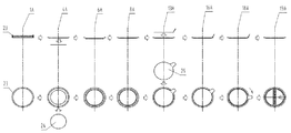
- the working principle as shown in Fig. 1, Fig. 2, Fig.
- the laminated metal cover is automatically dropped into the synchronous belt type transport mechanism 26 by the cover device in the cover lower cover device 1a (see application for all of the 2015206230026 patent), intermittent Handling forward, intermediate hole punching, intermediate hole bending and deep drawing, intermediate hole crimping, dust removal, preheating, die cutting aluminum foil (film) and pre-sealing, heat sealing, cooling and finishing at station 4a-22a
- the production process of pulling the handle, folding the handle, embossing or flattening, and fixing the handle, according to the production requirements of different easy-to-tear cover, the station of 4a-22a can be used in whole or in part, and the individual stations can be replaced.
- Synchronous belt handling mechanism 26 The background art adopts two sets of synchronous belts and intermediate turning wheels, as shown in FIG. 5, in which 27 is a turning wheel, the purpose is to reduce the length of the timing belt to reduce the timing belt. The precision caused by the heat expansion and contraction is reduced, the turning mechanism is complicated, the adjustment is very difficult, the cover rubbing into the card slot is easy to be scratched, and the scrap rate is high.
- the utility model adopts a single set of timing belts, removes the turning wheel, increases the width of the timing belt, adopts an enhanced timing belt with a built-in steel wire, and adds cooling water to keep the synchronous belt constant temperature, thereby reducing the synchronous deformation and ensuring the precision of handling. Simplified organization and improved yield.
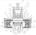
- Cover and cover device 1a The cover frame of the background art shown in FIG. 6 is composed of a plurality of limit levers 28, but since the cover is produced, the cover is applied to the bottom cover 23 due to the heavy cover. The pressure is large, so that the cutting force of the cover screw 31 is large, and the crushing of the edge of the cover is scrapped. As shown in FIG. 7, FIG. 8, and FIG. 9, the magnetic separator 101 is added on both sides of the storage rack, and the cover is suspended under the action of the magnetic force. The cover and the cover are spaced apart, which not only greatly reduces the bottom cover. The pressure of 23, while having fundamentally avoided the cover screw 31 to crush the cover 23.
- the present application adds an inverting cylinder 313, which can turn over the entire cover and cover mechanism to facilitate maintenance.
- the present application is improved on the cover screw cutter 31.
- the split screw cutter is composed of a body 31a, a cutter head 31b, and a washer 31c.
- the cover screw can be adjusted due to the thickness of the adjustment washer 31c.
- the height of the spiral groove at the beginning of the knife makes it possible to adapt to the cover with different hook heights.
- anti-drop cover device the prior art does not have anti-drop cover device, the cover is easy to fall out, resulting in damage to the scrap and the mold, improved structure: as shown in Figure 11, Figure 12, Figure 13, Figure 14, punching in the middle hole Station 4a, intermediate hole bending and drawing station 6a, intermediate hole crimping station 8a, heat sealing station 16a, cooling and handle alignment station 18a, embossing and handle fixing station 19a, increased prevention
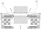
- the cover device, FIG. 11 is a flap type anti-drop cover device, and the flap 32 ensures that the cover is accurately dropped into the transport jig of the transport mechanism when the cover is lowered under gravity; FIG.
- the lift plate 35 is Under the action of gravity, the cover is accurately dropped into the carrying fixture of the transport mechanism when it is lowered; in addition to the above-mentioned work station, the other stations are equipped with the anti-drop cover device as shown in Fig. 12, and the shift lever 33 ensures that the cover moves horizontally.
- the calibration block 34 can And mold lift down, the deviation can be calibrated while moving the lid, the lid especially in the production of D-calibrated central hole effect is obvious.
- the dust removing device of FIG. 15 is added to the station shown in FIG. 1 and FIG. 2, and the high-pressure air blown by the air knife 36 blows the cover dust into the suction hood 37, and the negative pressure generated by the suction hood 37 is generated. The pressure is discharged to a safe position, and the cover is ensured not to be blown off by the lever 33.
- Preheating Since it is difficult to instantaneously heat the metal cover to the sealing temperature by conduction or radiation in the background art, there is no way to improve the production efficiency of the device, and the sealing becomes a bottleneck restricting the efficiency of the whole device.
- the present application adopts an induction heating preheating method at least one position in the aluminum foil pre-sealing station of 10a-12a in FIG. 1 and FIG. 2, which can quickly bring the cover to the sealing temperature and change the conduction or radiation manner in the background art.
- the drawbacks of preheating In order to prevent the cover from being pushed down by the induction magnetic force, the preheating station adopts the shift lever 33 of Fig. 12 to prevent the cover from falling, and the shift lever 33 is made of a non-metal material.
- the prior art unwinding reel is a mechanical expansion shaft, which requires special tools to operate, which is time-consuming and laborious, and there is no rack and pinion mechanism at both ends of the tension roller, which causes the tension roller to tilt and yaw, so that the aluminum foil or film The tension is not constant.
- the gear 40 is mounted on both ends of the tension roller 44, and the gear 40 meshes with the racks 41 on both sides.
- the tension roller 44 When the aluminum foil or film 45 is dragged by the film feeding mechanism, the tension roller The two ends of the 44 are synchronously raised under the action of the rack and pinion mechanism, which ensures that the tension between the aluminum foil or the film is uniform, so that the stepping pitch of the aluminum foil or the film is accurate; when the tension roller 44 is raised upward, the shaft end is induced.
- the control system activates the unwinding motor 39, and the unwinding motor drives the unwinding drum 38 until the tension roller 44 descends, the shaft end senses the lower position sensor 43, the unwinding motor stops, and the actual lifting range of the tension roller 44 is greater than
- the distance between the upper and lower sensors 42, 43 is such that a buffer stroke is left to prevent the tension from being out of control.
- the reel 38 is provided with an inflation shaft, and the fixing of the aluminum foil (film) roll saves time and effort.
- Aluminum foil (film) station 13a Background technology: A set of film pulling device is used at the waste film end to easily break the aluminum foil (film); the upper die cutting die and the upper head are integrated, and the heat of the sealing is easy to make The die-cutting die is thermally expanded, affecting the gap of the die to damage the die; the station has no anti-drop cover device. As shown in FIG. 17, FIG. 17-1 and FIG. 18, the present application adopts a set of servo-driven film feeding devices at the film inlet end and the waste film end, and the punched aluminum foil or film is subjected to the first feeding and pulling.
- the pressure of the rubber roller 46 can be adjusted by the stroke and air pressure of the cylinder 47 to ensure that the aluminum foil (film) does not run off; there is a gap between the upper die cutting die 49 and the pre-head 50 There is a certain gap, and the upper and lower die-cutting molds 49 have a cooling water tank through the cooling water to ensure a constant gap of the punching; the pre-head 50 has a vacuum port 51 and a blowing port 52, and the aluminum foil or film is After rushing down, it is vacuum-adsorbed on the pre-sealing head 50 to prevent the aluminum foil or film from shifting.
- the pre-sealing head 50 descends to seal the aluminum foil or film on the cover 50, and the pre-sealing head 50 ascends while the blowing port 52 passes into the compressed air.
- the cover 60 is blown away from the pre-sealing head 50, and is prevented from falling when the cover 60 is moved up and down at high speed.
- At least two sets of flaps 55 are used in the lower die-cutting mold 54, and at least two sets of high-temperature magnets 56 are used in the lower head 57. It is ensured that the cover 60 is accurately dropped into the carrying jig of the transport mechanism.
- the waste film holder 48 is modified to a downwardly inclined structure at the waste film end, so that the waste film 59 flows out smoothly, as shown in FIG.
- the punching center distance of the aluminum foil (film) is different, so that the aluminum foil or film needs to have a certain oblique angle with the running direction of the cover conveying mechanism
- the application adopts the method shown in FIG. 18, and the mounting frame 62 of the punching die is provided with at least two annular grooves 63, and is connected to the frame 61 by bolts in the annular groove 63, so that the entire group of die cutting dies and
- the adjustment direction of the running direction of the handling mechanism is simple and convenient to solve the requirements of saving aluminum foil or film and adapting to different cover types.
- Sealing station 16a In the background art, since the sealing pressure is not adjustable, and there is no anti-dropping device, when the sealing D-type is easy to tear, the sealing at the D-shaped straight edge is either sealed or bulged, directly affecting To the quality of the product. As shown in FIG. 19, in order to realize the adjustment of the sealing pressure, a force adjustment screw 65 is added, and the spring plate 66 is moved by the force adjustment screw 65 to adjust the compression force of the spring 67, and a cooling water passage 76 is added to ensure that the spring force of the spring 67 is not affected. . Third, in order to ensure that the sealing temperature is not lost, the present application is provided with at least one temperature sensor 68 in the upper heating block 69 and the lower heating block 70, respectively.
- the present application adds a flap 32 and at least two sets of high temperature magnets 56 are used in the lower head 57.
- Cooling and handle alignment device 18a Since there is no cooling function in the background art, it not only directly affects the formation of the sealing strength, but also corrects the servo motor. Therefore, the positive component is active and the lower component is driven. The speed of the device is easy to crush the cover, and the servo motor is not equipped with a reducer, so it is bulky under the same torque. In this application, the servo motor 82 is placed underneath, and the correcting component is activated. The purpose of the design is to find the positive disk 83 to contact the cover first, and the servo motor can be started in advance to improve the running speed of the device; When the D-type easy-to-tear cover of Fig.
- the lower finding disk 83 can be made into a D-shaped groove to correspond to the D-shaped bead of the D-shaped cover, and the D-shaped edge can be calibrated to prevent subsequent station crushing.
- the cover; three is for the convenience of installation, the planetary reducer 81 is connected to the alignment servo motor 82, which reduces the power and volume of the servo motor.
- a blowing port 78 is provided in the upper aligning member 79 for ensuring that the cover moves down with the aligning member under the action of the airflow and accurately falls into the carrying jig of the transport mechanism, and the aligning member 79 is aligned.
- Cooling nozzles 77, 80 are provided in the member 84, and the cooling water in the cooling nozzles 77, 78 is used to cool the upper aligning plate 85 and the lower aligning plate 83, so that the temperature of the easy-to-tear cover is drastically lowered to form a sealing strength.
- the V-shaped guide edge 86 can be gradually guided, while the outer region 87 of the V-shaped guide edge 86 ensures that the handle has pressed against the rim of the eyelet 72 prior to folding, preventing the cover from flipping over the cover due to the folding force.
- Embossing or flattening station 19a Since there is no cooling function and anti-drop device in the background art, it is easy to cause the hot sealing aluminum foil or film to stick to the embossing lower mold to cause the card cover. As shown in Fig. 24, in the present application, a cooling water passage 91 is added to the upper mounting plate 90 of the embossing upper mold 92, and a cooling water passage 95 is added to the lower mounting plate 94 of the embossing lower mold 93, and the cooling water passages 91, 95 are used.
- Cooling water to cool the easy-to-tear cover thus avoiding the capping phenomenon caused by insufficient cooling time of the high-speed production cover;
- the flap 32 is added to prevent the cover from falling;
- the third is to make the easy-to-clip aluminum foil or
- the depth of the film is uniform in the whole plane, and at least three limit adjusting screws 89 are added to the upper embossing part, and the depth of the pattern is ensured by adjusting the limit distance of the screw.
- an easy-to-tear cover production line 2 which is characterized by comprising an electric control box, an aluminum foil or film unwinding device, a synchronous belt type conveying mechanism, a cover lower cover device, an intermediate hole forming device, a preheating device, a die-cut aluminum foil Or membrane and pre-sealing device, heat sealing device, cooling and handle alignment device, folding handle device, embossing or flattening device; (1) in the sub-covering device: a. in the mounting plate and the lower cover The flipping cylinder is added between the two; b.
- the split screw cutter is composed of the body, the cutter head and the gasket, and the height of the spiral groove at the beginning of the split screw cutter can be adjusted by adjusting the thickness of the gasket; (2) Forming in the middle hole The device, the heat sealing device, the cooling and handle alignment device, the embossing and the handle fixing device are respectively provided with anti-drop cover devices; (3) at least one position in the preheating device before the aluminum foil pre-sealing Induction heating is used; (4) in the embossing or flattening device, a cooling water channel is added in the upper mounting plate of the embossing upper mold, and a cooling water channel is added in the lower mounting plate of the embossing lower mold, and cooling is performed in the cooling water channel. Water to cool the easy to tear cover.
- the utility model adopts a single set of synchronous belts and removes the turning wheel, which can realize high-speed manufacturing and easy tearing of the cover, and can avoid the friction damage of the cover, and the genuine rate is high;
- the second is the cooling water to make the timing belt
- the method of maintaining the constant temperature not only reduces the deformation of the synchronization, but also ensures the accuracy of the transportation, and simplifies the mechanism and improves the yield;
- the third is the setting of the inverted cylinder in the cover and the lower cover device, thereby realizing the entire cover and the lower cover mechanism to be turned over, which is convenient.
- the adjustable gasket in the cover screw cutter is designed to adapt to the cover with different hook height; the fifth is to prevent the design of the cover device, and ensure that the cover falls accurately into the transport fixture of the transport mechanism when it is lowered; Sixth, the design of the dust removal device ensures that the dust of the cover is blown into the suction hood to avoid environmental pollution.
- the seventh is the design of the preheating device, which makes the metal cover instantaneously heated to the sealing temperature, which effectively improves the equipment.
- the production efficiency; eight is the aluminum foil (film) unwinding device, the reel is made of an air-expansion shaft, which saves time and labor when fixing the aluminum foil (film) roll;
- Each of the waste film ends adopts a set of servo-driven film feeding devices, and the punched aluminum foil (film) is subjected to a small pulling force by means of first feeding and pulling, thereby avoiding the defect that the aluminum foil (film) is easily broken;
- the design of the water cooling structure realizes that the sealing temperature can be controlled; the eleven is to find the servo motor under the lower position, so that the next positive disk is contacted with the cover, and the servo motor is started in advance to improve the running speed of the device; It is the design of multiple limit adjusting screws on the upper embossing parts in the embossing or flattening device to ensure the consistency of the pattern.
- Figure 1 is a simplified schematic view of a tear-off cover line.
- Figure 2 is a top plan view of Figure 1.
- Fig. 3 is a front elevational view showing the appearance of Fig. 1.
- Figure 4 is a schematic view of the forming process of the cover.
- Figures 5 and 6 are schematic views of CN105081128A.
- Fig. 7 is a front elevational view showing the cover lower cover device.
- Figure 8 is a side elevational view of Figure 7.
- Figure 9 is a top plan view of Figure 7.
- Fig. 10 is a schematic structural view of a split screw cutter.
- Figure 11 is a schematic view of a flap type anti-drop cover device.
- Figure 12 is a schematic cross-sectional view of the cover bar.
- Figure 13 is a schematic view of a lift type anti-drop cover device.
- Figure 14 is a top plan view of Figures 11, 12 and 13.
- Figure 15 is a schematic view of a dust removing device.
- Figure 16 is a top plan view of an aluminum foil (film) unwinding device.
- Figure 16-1 is a front elevational view of the aluminum foil (film) unwinding device.
- Figure 17 is a schematic view of an aluminum foil (film) and a pre-sealing device.
- Figure 17-1 is a partially enlarged schematic view of an aluminum foil (film) and a pre-sealing device.
- Fig. 18 is a schematic view showing a mounting frame for an aluminum foil (film) and a pre-sealing device.
- Figure 19 is a schematic view of a heat sealing device.
- Figure 20 is a schematic view of a D-shaped tear-off cover.
- Figure 21 is a bottom plan view of the D-shaped upper head in the heat sealing device.
- Figure 22 is a schematic view of the cooling and handle alignment device.
- Figure 23 is a schematic view of a folding handle device.
- Figure 24 is a schematic illustration of an embossing or flattening device.
- Example 1 Referring to Figures 1-25.
- An easy-to-tear cover production line 2 comprising an electric control box 01, an aluminum foil or film unwinding device 02, a timing belt type transport mechanism 26, a cover lower cover device 1a, an intermediate hole forming device (4a, 6a, 8a), and preheating
- An inverting cylinder 313 is added between the mounting plate 311 and the lower cover frame 312; b.
- the sub-covering screw blade is composed of the body 31a, the cutter head 31b, and the spacer 31c, and the thickness of the adjusting washer 31c can be adjusted.
- the spiral groove height at the beginning of the cover screw; the intermediate hole forming device (4a, 6a, 8a), the heat sealing device 16a, the cooling and handle alignment device 18a, and the timing belt handling mechanism 26 of the embossing and handle fixing device 19a Each of the preheating devices 10a-12a before the pre-sealing of the aluminum foil is inductively heated; the upper mounting plate of the embossing upper mold 92 is in the embossing or flattening device 19a.
- a cooling water channel 91 is added to the 90, and a cooling water channel 95 is added to the lower mounting plate 94 of the embossing lower mold 93.
- the easy-to-tear cover is cooled by the cooling water in the cooling water channels 91, 95.
- the intermediate hole forming device (4a, 6a, 8a) is composed of an intermediate hole punching device 4a, an intermediate hole bending and drawing device 6a, and an intermediate hole crimping device 8a.
- the intermediate hole forming device (4a, 6a, 8a) is constituted by an intermediate hole punching and bending device (4a, 6a) and an intermediate hole crimping device 8a.
- the magnetic separator 101 is added to both sides of the cover rack in the cover lower cover device 1a.
- the folding handle device 18aa is placed after the embossing or flattening device 19a, and the handle fixing device 20a is added and the handle fixing device 20a is placed behind the folding handle device 18aa.
- the anti-drop cover device is a flap type anti-drop cover device or a lift type anti-drop cover device; in the flap type anti-drop cover device, the flap 32 ensures that the cover is accurately dropped into the transport mechanism when the cover is lowered under the force of gravity In the clamp, the lifting plate 35 of the lifting type anti-drop device ensures that the cover is accurately dropped into the carrying jig of the transport mechanism when the cover is lowered by gravity.
- the cover lower cover device 1a, the intermediate hole punching device 4a, the intermediate hole bending and drawing device 6a, the intermediate hole crimping device 8a, the die-cut aluminum foil or film and the pre-sealing device 13a, the heat sealing device 16a, the embossing or A photodetector is added above or below the flattening device 19a and the rear station.
- a calibration block 34 is provided in the previous station of the intermediate hole bending and drawing device 6a, the intermediate hole crimping device 8a, the die-cut aluminum foil or film and the pre-sealing device 13a, and the heat sealing device 16a.
- a dust removing device 9a is provided at a station in front of the preheating device 10a-12a. In the dust removing device 9a, the air suction hood 37 is above the air knife 36 and the high pressure wind blown by the air knife 36 blows the dust of the cover into the air hood. In 37, the negative pressure generated by the suction hood 37 is discharged to a safe position, and the cover is passed through the lever 33 to ensure that the cover is not blown off.
- a set of servo-driven film feeding devices are used at the film inlet end and the waste film end, and the pressure of the rubber roller 46 can be adjusted by the stroke and air pressure of the cylinder 47.
- the pre-sealing head 50 of the die-cut aluminum foil or film and pre-sealing device 13a has a vacuum port 51 and a blowing port 52.
- At least two sets of flaps 55 are used in the lower die-cutting mold 54, and at least two sets of high-temperature magnets 56 are used in the lower head 57.
- the waste film end of the die-cut aluminum foil or film and pre-sealing device 13a is modified to a downwardly inclined structure to make the waste film 59 flow smoothly.
- At least two annular grooves 63 are provided in the die-cutting frame 62 of the die-cut aluminum foil or film and the pre-sealing device 13a, and are connected to the frame 61 by bolts in the annular groove 63.
- An adjusting screw 65 is disposed on the adjusting screw 661 of the heat sealing device 16a, and the spring plate 66 is moved by the adjusting screw 65 to adjust the compressive force of the spring 67, and the upper heating block mounting plate 761 is provided with cooling.
- the water passage 76 ensures that the spring force of the spring 67 is not affected; at least one temperature sensor 68 is provided in the upper heating block 69 and the lower heating block 70, respectively.
- a heat insulating pad 762 is disposed under the upper heating block mounting plate 761; a heat insulating column 701 is installed between the lower heating block 70 and the lower heating block mounting plate 702, the end surface of the heat insulating column 701 is insulated, and the lower heating block mounting plate 702 is opened. Cooling water channel 703.
- a flap 32 is provided on the timing belt transport mechanism 26; at least two sets of high temperature magnets 56 are used in the lower head 57; and a recessed area of the lower end surface 75 of the upper head 71 in the die-cut aluminum foil or film and pre-sealing device 13a is 0.01 -0.2mm.
- the cooling and handle alignment device 18a is positioned below the servo motor 82, and the power output shaft of the servo motor 82 is connected to the power input end of the planetary reducer 81; the cooling and handle alignment station 18a is aligned.
- a blowing port 78 is provided in the member 79, and cooling water ports 77 and 80 are provided in the upper aligning member 79 and the lower aligning member 84, respectively.
- the cooling water in the cooling water ports 77 and 78 is used for cooling the upper aligning plate 85 and the lower portion. Find the positive 83.
- the folding handle device 18aa is provided with a V-shaped guiding edge 86.
- the easy-to-tear cover can be guided by a V when being translated in the direction of the arrow in the figure.
- the edge 86 is gradually aligned while the outer region 87 of the V-shaped guide edge 86 ensures that the handle has pressed against the edge of the eyelet 72 prior to folding.
- the spring pressure plate 901 in the upper embossing unit of the embossing or flattening device 19a is provided with at least three limit adjusting screws 89, and the depth of the pattern is ensured by adjusting the limit distance of the screws.
- the method for manufacturing the easy-to-tear cover comprises an electric control box 01, an aluminum foil or a film unwinding device 02, and the laminated metal cover is automatically dropped into the synchronous belt type transport mechanism 26 by the cover device in the cover lower cover device 1a, intermittently Front conveying, sequentially passing through the intermediate hole punching device 4a, the intermediate hole bending and drawing device 6a, the intermediate hole crimping device 8a, the preheating device 10a-12a, the die-cut aluminum foil or film and the pre-sealing device 13a, and the heat sealing device 16a
- the cooling and handle alignment device 18a, the folding handle device 18aa, the embossing or flattening device 19a complete the easy-to-tear cover production, and (1) the synchronous belt type
- the water keeps the timing belt in a constant temperature manner to reduce the synchronous deformation, and the handling accuracy is ensured;
- the inverting cylinder 313 is added between the mounting plate 311 and the lower cover frame 312, and the cylinder is turned over.
- the entire cover lower cover mechanism is turned over; (3) the intermediate hole punching device 4a, the middle hole bending and deep drawing device 6a, the intermediate hole crimping device 8a, the heat sealing device 16a, the cooling and handle alignment device 18a, Anti-embossing or flattening device 19a is provided with protection
- the cover device, the flap 32 or the lift plate 35 in the anti-drop cover device ensure that the cover is accurately dropped into the transport jig of the transport mechanism when descending under the action of gravity, and is easy to be disposed in the empty work station between the above devices.
- the cover lever 33 is torn off, so that the cover is normally dropped when moving horizontally; the cover lower cover device 1a, the intermediate hole punching device 4a, the intermediate hole bending and deep drawing device 6a, the intermediate hole crimping device 8a, and the punching A photodetector is attached to the upper or lower side between the cut aluminum foil or film and pre-sealing device 13a, the heat sealing device 16a, the embossing or flattening device 19a and the rear station to detect the state of the cover, and when the cover is not output by the transport mechanism Then, the machine alarm is stopped, and the calibration block 34 located at the middle hole bending and drawing device 6a, the intermediate hole crimping device 8a, the die-cut aluminum foil or film and the pre-sealing device 13a, and the heat sealing device 16a is placed on the cover.
- a dust removing device 9a is provided at the station in front of the preheating device 10a-12a, and the suction hood 37 in the dust removing device 9a is above the air knife 36, and the high pressure blown by the air knife 36 The wind blows the cover dust into the suction hood 37, and the suction hood 3 7 The generated negative pressure is discharged to a safe position, and the cover is ensured not to be blown off by the shift lever 33; (5) At least one position in the 10a-12a before the aluminum foil pre-sealing is preheated by induction heating to make the cover reach the sealing Temperature, and the preheating station uses the shift lever 33 to prevent the cover from falling; (6) a set of servo-driven film feeding devices are used in each of the film feeding end and the waste film end in the aluminum foil (film) pre-sealing device 13a, The method of first feeding and pulling back causes the punched aluminum foil or film to be subjected to a small pulling force,
- the pre-head 50 has a vacuum port 51 and a blowing port 52, and the aluminum foil or film is washed down and vacuum-adsorbed on the pre-head 50 to prevent the aluminum foil or film from being deflected, and then The pre-head 50 descends the aluminum foil or film on the cover 50, and the pre-head 50 is simultaneously
- the blow port 52 is vented with compressed air to blow the cover 60 away from the pre-sealing head 50.
- At least two sets of flaps 55 are employed in the lower die cutting die 54 and at least in the lower head 57.
- Two sets of high temperature magnets 56 thereby ensuring that the cover 60 is accurately dropped into the transport jig of the transport mechanism; at the waste film end, the waste film support plate 48 is modified to a downwardly inclined structure, so that the waste film 59 flows out smoothly;
- the force adjusting screw 65 disposed on the punching aluminum foil or film and the preloading device 13a adjusts the spring plate 66 to adjust the compression force of the spring 67, and is ensured by the cooling water passage 76 on the upper heating block mounting plate 761.
- the spring 67 spring force is not affected, and the sealing temperature is monitored by a plurality of temperature sensors 68 disposed in the upper heating block 69 and the lower heating block 70 to prevent the sealing temperature from being out of control, passing through the flap 32 and the lower head 57 in the anti-drop device.
- a plurality of sets of high temperature magnets 56 are provided to prevent the cover from being removed; (8)
- a planetary reducer 81 is connected to the alignment servo motor 82 in the cooling and handle alignment device 18a, and the alignment servo motor 82 is placed below, so that the alignment is corrected.
- Disk 83 first touches the lid and when needed When the D type is easy to tear the cover, the lower positive plate 83 can be made into a D-shaped groove to correspond to the D-shaped bead of the D-shaped cover, and the D-shaped edge can be calibrated to prevent the subsequent station from crushing the cover;
- the positive member 79 is provided with a blowing port 78 for ensuring that the cover is moved down into the carrying jig of the transporting mechanism with the downward aligning member under the action of the airflow, and is located in the upper aligning member 79 and the lower aligning member 84.
- the cooling water in the cooling nozzles 77, 80 is used to cool the upper alignment plate 85 and the lower alignment plate 83, so that the temperature of the easy-to-tear cover is drastically lowered to form a sealing strength; (9) the V-shaped guide provided in the folding handle device 18aa
- the edge 86 when the handle of the easily peelable aluminum foil (film) 73 is slightly offset, the easy-to-tear cover can be gradually guided by the V-shaped guide edge 86 while being translated in the direction of the arrow in the figure, while the V-shaped guide edge
- the outer region 87 of the 86 ensures that the handle has pressed against the rim of the eyelet 72 prior to folding to prevent the lid from flipping over the cover due to the folding force; (10) due to the cooling water channel in the upper mounting plate 90 of the embossing upper die 92 91.
- the lower mounting plate 94 of the embossing die 93 has a cooling water channel 95 therein, and the cooling water channels 91 and 95 are cold.
- the water effectively cools the easy-to-tear cover, avoiding the jamming phenomenon caused by the high-speed production of the cover; adjusting the plurality of limit positions on the spring pressure plate 901 provided in the upper embossing unit in the embossing or flattening device 19a Screw 89 ensures the consistency of the pattern.
- Embodiment 2 On the basis of Embodiment 1, when the manufacturing of the pull-tab or the rubber-coated handle is easy to tear, the folding handle device 18aa is placed after the embossing or flattening device 19a, and the handle fixing device 20a is added and the handle is fixed. The device 20a is located behind the folding handle device 18aa.
- Embodiment 3 On the basis of Embodiment 1, the lower alignment disk 83 may be formed in a D-shaped groove to correspond to the D-shaped bead of the D-shaped cover.
Abstract
一种易撕盖生产线,包括电控箱(01)、铝箔或膜放卷装置(02)、同步带式搬运机构(26)、分盖下盖装置(1a)、中间孔成型装置(4a,6a,8a)、预热装置(10a-12a)、冲切铝箔或膜及预封装置(13a)、热封装置(16a)、冷却及拉手找正装置(18a)、折叠拉手装置(18aa)、压花或压平装置(19a),所述分盖下盖装置中(1a)在安装板(311)和下盖架(312)之间增加翻转气缸(313),所述分盖下盖装置中(1a)的分盖螺刀由本体(31a)、刀头(31b)、垫片(31c)构成,通过调节垫片(31c)的厚度可调节分盖螺刀起始部位的螺旋槽高度;在同步带式搬运机构(26)上设有防掉盖装置;在铝箔预封前的预热装置(10a-12a)中至少有一个位置采用感应加热;压花或压平装置(19a)中在上下安装板内增设冷却水道(91,95)。该生产线能有效避免摩擦损伤,正品率高。
Description
本实用新型涉及一种既能实现高速制造易撕盖,又能避免盖子摩擦损伤,同时又具有正品率高的易撕盖生产线二,属易撕盖生产线制造领域。
CN103459061B、名称“撕去盖的制造设备和方法”,其包含一个用于盖元件和盖的输送器和多个沿输送器设置的用于盖元件和盖的加工站,所述加工站包含:密封站(5),该密封站构成用以将包含撕去接片(29)的薄膜部分(25)密封在成形为盖环(20′)的盖元件上;以及弯曲站(7),在该弯曲站中撕去接片(29)能够被朝向所述薄膜部分的上侧弯曲;其特征在于,在密封站与弯曲站之间设置胶合加工站(40),该胶合加工站具有装置(41),通过该装置能够输送胶合带(48)并且能够提供可从胶合带的载体带(58)上剥离的胶合贴片(30),所述胶合贴片在胶合加工站中能够被加设在事先被密封到盖环上的薄膜部分的上侧(26)上的一个位置上,在弯曲站中撕去接片处在该位置上。其制造方法,包括以下各步骤:供给撕去薄膜材料的带(35);从带(35)中冲出带有撕去接片(29)的薄膜部分(25);将薄膜部分(25)密封在盖环(20′)上,以及将撕去接片(29) 弯回到盖上,其特征在于下面的步骤:将从胶合带上分离的胶合贴片(30)加设到被密封的薄膜部分上的一个位置上,在所述撕去盖(28)上被弯回的撕去接片(29)处在该位置上。
CN101947608 A、名称“用于制造剥离盖的方法和装置”,其中首先,设置盖环,所述盖环具有法兰缘以及与其法兰缘斜坡连结的密封表面,其中,所述密封表面的另一个端部邻接盖环开口,以及然后,将剥离箔密封到所述密封表面上,其中,为了在所述密封步骤之后张紧所述剥离箔,将所述密封表面的跟随所述法兰缘斜坡的一段与所述剥离箔一起夹持在具有平坦的夹持表面的上夹持工具和下夹持工具之间,以及借助于压制工具,使所述密封表面的没有被所述上夹持工具和下夹持工具夹持的一段沿着所述上盖边缘的方向弯曲。其装置,其包括:用于盖部件和盖的传送设备;密封站,其形成为从密封箔冲压出箔段,并且将箔段的能够密封的底侧密封到盖环上,其中,沿着传送方向在所述密封站之后设置有处理站,所述处理站具有夹持工具,所述夹持工具具有平坦的夹持表面,借助所述夹持工具能够夹持与法兰缘斜坡邻接的密封表面,并且所述处理站具有压制工具,借助所述压制工具,密封边缘的未被所述夹持工具夹持的部分能够沿着所述上盖边缘的方向弯曲。
上述二件在先专利申请的不足之处:其公开的易撕盖设备中盖子的搬运方式是通过两个电机实现的,其中一个电机驱动曲柄连杆机构带动搬运架做往复运动,另一个电机驱动一根横向长轴带动搬运架的上下运动,从而实现盖子的抬起-前进-放下-退回的来回搬运方式,这种搬运方式生产速度慢,不能实现高速生产。
CN105081128 A、名称“一种易撕盖的加工设备及加工工艺”,包括用于输送盖体(14)的输送带(1),所述输送带(1)上依次设有用于将盖体(14)依次放置在输送带(1)上的盖体输送单元(2)、用于对位于输送带(1)上的盖体(14)进行加工的盖体加工单元、用于从箔带上冲出盖膜的盖膜加工单元(7)和用于将盖膜固定在位于输送带(1)上的盖体(14)上的盖膜密封单元,所述输送带(1)上均匀分布于有用于固定盖体(14)的固定件(12)。
所述盖体(14)加工单元和盖膜加工单元(7)之间还设有盖体翻转单元(6),所述盖体翻转单元(6)包括呈圆盘状的翻转盘(15)和固定在翻转盘(15)中心的转轴(16),所述的转轴(16)水平设置且垂直于翻转盘(15),所述的翻转盘(15)上均匀开设有若干呈条状的定位槽(17),所述定位槽(17)与翻转盘(15)的直径重合设置。所述定位槽(17)底部向翻转盘(15)中心凹入。所述的盖膜密封单元包括预密封装置(8)和主密封装置(9),所述的预密封装置(8)位于盖膜加工单元(7)和主密封装置(9)之间,所述的盖膜加工单元(7)和预密封装置(8)为一体式结构。所述的盖体输送单元(2)
包括输送架,所述的输送架上固定有竖直设置的储料架(20),所述的储料架(20)包括至少三根竖直设置且环形布置的限位杆(18),所述储料架(20)的底部设有分料装置,所述的分料装置包括至少三个均匀分布在储料架(20)底部且可转动的分料刀(19),所述的分料刀(19)呈扁圆柱状且竖直设置,所述的分料刀(19)的外侧开设有螺纹槽且分料刀(19)部分伸入储料架(20)内,所有分料刀(19)之间通过同步带或齿轮相连。所述的输送带(1)上每四个固定件(12)为一组用于固定盖体(14),所述的输送带(1)包括两条平行设置的带体(11);每一组中的四个固定件(12)中的两个位于一条带体(11)上,另外两个位于另一条带体(11)上;所述固定件(12)上具有用于支撑盖体(14)底部的托起部(12a)和用于挡住盖体(14)
侧部的阻挡部(12b)。其易撕盖加工工艺,在同一条用于输送盖体(14)的输送带(1)上依次完成下列步骤:A、盖体(14)的输送,将盖体(14)依次放置在输送带(1)上;B、盖体(14)的加工,对盖体(14)完成通孔冲压、通孔折边和通孔圆边;C、盖膜的加工,从箔带上通过冲压冲出盖膜;D、盖膜密封,将盖膜密封固定在盖体(14)上。所述的步骤D 包括下列步骤:D1、预密封,与步骤C在同一个模块单元上同时进行,将冲压出的盖膜直接的初步密封固定在盖体(14)上;D2、主密封,在盖膜密封固定在盖体(14)上。
其不足之处:该申请对盖子搬运方式为前后两组同步带加翻转盘的形式实现,由于在中间增加翻转盘(如图5所示,图中27为翻转盘),不仅翻转盘结构复杂,调整难度很大,而且盖子摩擦进入翻转盘卡槽容易擦伤,废品率高。
本实用新型的设计目的之一,避免背景技术中的不足之处,设计一种既能实现高速制造易撕盖,又能避免盖子摩擦损伤,同时正品率高。
本实用新型的设计目的之二,在背景技术的基础上,通过在分盖下盖装置中储盖架两侧增加磁力分张器,减轻了底部盖子的压力,避免分盖螺刀压伤盖子,并且通过增加了翻转气缸,可以使整套分盖下盖机构翻转,方便检修维护。
本实用新型的设计目的之三,在背景技术的基础上,通过对分盖螺刀中调节垫片的厚度调整,以适应不同钩边高度的盖子。
本实用新型的设计目的之四,在背景技术的基础上,通过在中间孔冲切装置、中间孔折弯拉深装置、中间孔卷边装置、热封装置、冷却及拉手找正装置、压花及拉手固定装置增加防止掉盖装置,以解决背景技术存在的盖子易掉出,所造成废品和模具损坏。
本实用新型的设计目的之五,在背景技术的基础上,通过在同步带式搬运机构上设置除尘装置,涂层的马口铁或铝合金盖子在冲压过程中所产生涂料粉或金属粉吸走。
本实用新型的设计目的之六,在背景技术的基础上,通过在铝箔预封前工位中至少有一个位置采用感应加热的预热方式,快速高效节能的使盖子达到封口温度。
本实用新型的设计目的之七,在背景技术的基础上,通过在进膜端和废膜端各采用一组伺服驱动送膜装置,使冲切过的铝箔(膜)受到较小的拉力,避免铝箔(膜)被拉断现象的发生。
本实用新型的设计目的之八,在背景技术的基础上,在冲切模具的安装架上至少设置二个环形槽,在环形槽内通过螺栓和机架相连,使整组冲切模具和搬运机构的运行方向调节角度,解决了节省铝箔(膜)和适应不同盖型的要求。
本实用新型的设计目的之九,在背景技术的基础上,将找正伺服电机下置,改下找正部件为主动,使找正伺服电机可以提前启动,提高了设备的运行速度,并且在上找正部件、下找正部件内分别采用冷却水冷却上找正盘和下找正盘,使易撕盖的温度急剧下降,形成封口强度。
本实用新型的设计目的之十,在背景技术的基础上,为了使易撕盖铝箔(膜)上压出的在整个平面内深浅度一致,在上压花部件增设至少三颗限位调节螺丝,通过调节螺丝的限位距离保证花纹的深浅一致。
为了实现上述设计目的,本实用新型的设计方案是:如图20所示,易撕盖由有中间孔的金属圈72、封在其上的带有拉手易撕铝箔(膜)73构成。(详见本申请人所有201420548383.1专利),图4为易撕盖的生产工艺过程:分盖下盖1A、中间孔冲切4A、中间孔折弯拉深6A、中间孔卷边8A、冲切铝箔(膜)及预封13A、热封16A、冷却及拉手找正18A、折叠拉手和压花及拉手固定19A。其工作原理:如图1、图2、图3,层叠的金属盖子在分盖下盖装置1a通过分盖装置自动落入同步带式搬运机构26上(见申请本人所有2015206230026专利),间歇的往前搬运,依次在工位4a-22a上完成中间孔冲切、中间孔折弯拉深、中间孔卷边、除尘、预热、冲切铝箔(膜)及预封、热封、冷却及拉手找正、折叠拉手、压花或压平、拉手固定的生产工序,依照不同易撕盖的生产要求,4a-22a的工位可全部或部分采用,个别工位可更换顺序。
1、同步带式搬运机构26:背景技术采用两组同步带加中间翻转轮的结构,如图5所示,图中27为翻转轮,目的是想减少同步带的长度,以减少同步带的热涨冷缩造成的精度降低,翻转机构复杂,调整难度很大,盖子摩擦进入卡槽容易擦伤,废品率高。本申请采用单组同步带,去掉翻转轮,并且增加同步带宽度、采用内置有钢丝的增强同步带、加冷却水使同步带保持恒温的方式减少同步的变形的措施,保证了搬运的精度,简化了机构,提高了成品率。
2、分盖下盖装置1a:如图6所示背景技术的储盖架采用多根限位档杆28构成,但是由于生产铁盖时,因盖子较重,作用在底部的盖子23上的压力很大,使分盖螺刀31的切入力很大,造成盖子边缘的压伤报废。本申请如图7、图8、图9所示,在储盖架两侧增加磁力分张器30,在磁力作用下使盖子悬浮,盖子与盖子之间有一定间隔,不仅大大减轻了底部盖子23的压力,而有从根本上避免分盖螺刀31压伤盖子23。其次,本申请增加了翻转气缸313,可以使整套分盖下盖机构翻转,方便检修维护。三是如图10所示,本申请在分盖螺刀31上做了改进,分盖螺刀由本体31a、刀头31b、垫片31c构成,由于调节垫片31c的厚度可调节分盖螺刀起始部位的螺旋槽高度,因此可以适应不同钩边高度的盖子。
3、防掉盖装置:现有技术没有防掉盖装置,盖子容易掉出,造成废品和模具损坏,改进结构:如图11、图12、图13、图14所示,在中间孔冲切工位4a、中间孔折弯拉深工位6a、中间孔卷边工位8a、热封工位16a、冷却及拉手找正工位18a、压花及拉手固定工位19a,增加了防止掉盖装置,图11为翻板式防掉盖装置,翻板32在重力作用下确保将盖子在下降时准确落入搬运机构的搬运夹具内;图13为升降式防掉盖装置,升降板35在重力作用下确保将盖子在下降时准确落入搬运机构的搬运夹具内;除上述工位外,其余工位安装了如图12的防掉盖装置,档杆33确保了盖子在水平移动时的掉落;为了防止盖子卡在模具内没有输出造成模具损坏,在图1、图2中的1aa、4aa、6aa、8aa、13aa、16aa、19aa位置增设了光电检测,如盖子没有被搬运机构输出则机器报警停机;图12中校准块34可随模具升降而升降,可校准盖子在移动时的偏差,尤其是在生产D型中间孔的盖子时校准效果明显。
4、除尘装置:因国情需要,我国的罐头盖子多数采用有涂层的马口铁或铝合金,在冲压过程中难免产生涂料粉或金属粉,污染盖子。为此本申请在图1、图2的9a所示工位增加如图15的除尘装置,风刀36吹出的高压风将盖子粉尘吹入吸风罩37内,由吸风罩37产生的负压排出至安全位置,盖子通过档杆33保证不被吹掉。
5、预热:由于在背景技术中很难通过传导或辐射方式将金属盖子瞬间加热到封口温度,因此背景技术没有办法提升设备的生产效率,封口成为制约整台设备效率提升的瓶颈。本申请在如图1、图2中的10a-12a的铝箔预封前工位中至少有一个位置采用感应加热的预热方式,可以快速使盖子达到封口温度,改变背景技术中传导或辐射方式预热的弊端。为防止盖子被感应磁力推落,预热工位采用了图12中档杆33,防止盖子掉落,档杆33采用非金属材质。
6、铝箔或膜放卷装置:现有技术的放卷轴为机械胀轴,需要专用工具操作,费时费力,且张力滚筒两端无齿轮齿条机构,导致张力滚筒倾斜偏摆,使铝箔或膜张力不恒定。本申请如图16、图16-1所示,在张力滚筒44两端安装有齿轮40,齿轮40和两侧的齿条41啮合,当铝箔或膜45被送膜机构拖动时,张力滚筒44两端在齿轮齿条机构作用下同步向上升起,保证了铝箔或膜两端的张力是一致的,从而使铝箔或膜的步进间距精准;当张力滚筒44向上升高,其轴端感应到上位传感器42,控制系统就启动放卷电机39,放卷电机驱动放卷轴38,直至张力滚筒44下降,其轴端感应到下位传感器43,放卷电机停止,张力滚筒44的实际升降范围大于上下位传感器42、43之间的距离,这样就留有缓冲行程,防止张力失控。放卷轴38采用气胀轴,固定铝箔(膜)卷省时省力。
7、冲铝箔(膜)工位13a:背景技术在废膜端采用一组拉膜装置,容易拉断铝箔(膜);上冲切模具和上封头为一体结构,封口的热量容易使上冲切模具受热膨胀,影响冲模的间隙损坏模具;该工位没有防掉盖装置。本申请如图17、图17-1、图18所示,在进膜端和废膜端各采用一组伺服驱动送膜装置,采用先送后拉的方式使冲切过的铝箔或膜受到较小的拉力,铝箔或膜不容易断,胶辊46的压力可通过气缸47的行程和气压来调节,保证铝箔(膜)不跑偏;上冲切模具49和预封头50之间有一定缝隙,且上冲切模具49上及下冲切模具54内有冷却水槽通过冷却水恒温,保证冲切的间隙恒定;预封头50上有真空口51和吹气口52,铝箔或膜被冲下后通过真空吸附在预封头50上,防止铝箔或膜偏移,然后预封头50下行将铝箔或膜封在盖子50上,预封头50上行同时吹气口52通入压缩空气将盖子60吹离预封头50,为防止盖子60上下高速移动时掉落,在下冲切模具54内采用了至少两组翻板55,在下封头57内采用至少两组高温磁铁56,以此保证盖子60准确落入搬运机构的搬运夹具内。在废膜端将废膜托板48改进成向下倾斜的结构,使废膜59流出顺畅,如图2所示。其次,为了节省铝箔,生产不同盖型的易撕盖,铝箔(膜)的冲切中心距是不一样的,这样铝箔或膜就需要和盖子的搬运机构的运行方向有一定的斜角,本申请采用如图18所示的方式,冲切模具的安装架62上设置有至少2个环形槽63,在环形槽63内通过螺栓和机架61相连,这样就可使整组冲切模具和搬运机构的运行方向调节角度,简单方便解决了节省铝箔或膜和适应不同盖型的要求。
8、封口工位16a:背景技术中由于封口压力不可调,并且没有防掉盖装置,在封口D型易撕盖时,D形直边处的封口要么被封住,要么鼓起,直接影响到产品的品质。本申请如图19所示,为了实现封口压力的调节,增设调力螺丝65,用调力螺丝65移动弹簧板66来调节弹簧67的压缩力,同时增设冷却水道76保证弹簧67弹力不受影响。三是为保证封口温度不失控,本申请在上加热块69和下加热块70内分别设有至少一个温度传感器68。四是为防止掉盖,本申请增设翻板32及在下封头57内采用至少两组高温磁铁56。五是本申请如图20、图21所示,为防止D型易撕盖D形直边处(阴影部分74)被封住或鼓起,在上封头71的虚线部位75区域凹进0.01-0.2mm。
9、冷却及拉手找正装置18a:由于背景技术中没有冷却功能, 不仅直接影响封口强度的形成,而且找正伺服电机上置所以上找正部件为主动、下找正部件为从动,影响设备的速度且容易压伤盖子,并且找正伺服电机没有设置减速机,因此在同等扭矩下体积大。本申请将找正伺服电机82下置,改下找正部件为主动,这样设计的目的在于:下找正盘83先接触盖子,找正伺服电机可以提前启动,提高了设备的运行速度;其次,当生产如图20的D型易撕盖时,下找正盘83可做成D形的凹槽以对应D型盖的D形卷边,既可校准D形边防止后续工位压伤盖子;三是为了便于安装,在找正伺服电机82上连接有行星减速机81,这样减小了伺服电机的功率和体积。四是在上找正部件79内设有吹气口78,用于确保盖子在气流作用下随下找正部件下移准确落入搬运机构的搬运夹具内,在上找正部件79、下找正部件84内分别设有冷却水口77、80,冷却水口77、78内冷却水用于冷却上找正盘85和下找正盘83,从而使易撕盖的温度急剧下降,形成封口强度。
10、折叠拉手工位:在背景技术中无导向装置及防止盖子翻起掉盖的结构,生产铝易撕盖时,拉手折叠容易弯斜,且盖子容易被折叠器挂翻。本申请如图23所示,折叠器88增设有V形的导向边86,当易撕盖的铝箔(膜)73的拉手有一点偏移时,易撕盖在沿着图中箭头方向平移时可由V形的导向边86逐渐导正,同时V形的导向边86的外部区域87确保拉手在折叠前已经压住金属圈72的边沿,防止因折叠力而使盖子翻起掉盖。
11、压花或压平工位19a:由于背景技术中无冷却功能和防掉盖装置,容易使热的封口铝箔或膜粘住压花下模上造成卡盖。本申请如图24所示,在压花上模92的上安装板90内增设冷却水道91,在压花下模93的下安装板94内增设冷却水道95,用冷却水道91、95内的冷却水来冷却易撕盖,这样就避免了因高速生产盖子冷却时间不足造成的卡盖现象;其次,为防止掉盖,增设翻板32防止盖子掉落;三是为了使易撕盖铝箔或膜上压出的在整个平面内深浅度一致,在上压花部件增设至少三颗限位调节螺丝89,通过调节螺丝的限位距离保证花纹的深浅一致。
技术方案:一种易撕盖生产线二,其特征是包括电控箱、铝箔或膜放卷装置、同步带式搬运机构、分盖下盖装置、中间孔成型装置、预热装置、冲切铝箔或膜及预封装置、热封装置、冷却及拉手找正装置、折叠拉手装置、压花或压平装置;(1)所述分盖下盖装置中:a.在安装板和下盖架之间增加了翻转气缸;b.分盖螺刀由本体、刀头、垫片构成,通过调节垫片的厚度可调节分盖螺刀起始部位的螺旋槽高度;(2)在中间孔成型装置、热封装置、冷却及拉手找正装置、压花及拉手固定装置的同步带搬运机构上分别设有防掉盖装置;(3)在铝箔预封前的预热装置中至少有一个位置采用感应加热;(4)所述压花或压平装置中在压花上模的上安装板内增设冷却水道,在压花下模的下安装板内增设冷却水道,用冷却水道内的冷却水来冷却易撕盖。
本实用新型与背景技术相比,一是采用采用单组同步带,去掉翻转轮,既能实现高速制造易撕盖,又能避免盖子摩擦损伤,同时正品率高;二是冷却水使同步带保持恒温的方式,不仅减少同步的变形,保证了搬运的精度,而且简化了机构,提高了成品率;三是分盖下盖装置中翻转气缸设置,实现了整套分盖下盖机构翻转,方便检修维护;四是分盖螺刀中可调垫片设计,适应于不同钩边高度的盖子;五是防止掉盖装置的设计,确保将盖子在下降时准确落入搬运机构的搬运夹具内;六是除尘装置的设计,确保了盖子的粉尘被吹入吸风罩,避免了对环境的污染;七是预热装置的设计,使金属盖子瞬间加热到封口温度成为现实,有效地提高了设备的生产效率;八是铝箔(膜)放卷装置中放卷轴采用气胀轴,使得固定铝箔(膜)卷时省时省力;九是在进膜端和废膜端各采用一组伺服驱动送膜装置,采用先送后拉的方式使冲切过的铝箔(膜)受到较小的拉力,避免了铝箔(膜)容易断的缺陷;十是封口装置水冷却结构的设计,实现了封口温度可控;十一是找正伺服电机下置,使下找正盘先接触盖子,实现了找正伺服电机提前启动,提高了设备的运行速度;十二是压花或压平装置中上压花部件多颗限位调节螺丝的设计,保证花纹的深浅一致。
图1是易撕盖生产线的简易示意图。
图2是图1的俯视示意图。
图3是图1的外观主视示意图。
图4是盖子的成形过程示意图。
图5和图6是CN105081128 A的示意图。
图7是分盖下盖装置的主视示意图。
图8是图7的侧视示意图。
图9是图7的俯视示意图。
图10是分盖螺刀的结构示意图。
图11是一种翻板式防掉盖装置示意图。
图12是防掉盖挡杆的截面示意图。
图13是升降式防掉盖装置示意图。
图14是图11、图12和图13俯视示意图。
图15是除尘装置的示意图。
图16是铝箔(膜)放卷装置俯视示意图。
图16-1是铝箔(膜)放卷装置正视示意图。
图17是冲铝箔(膜)及预封装置示意图。
图17-1是冲铝箔(膜)及预封装置局部放大示意图。
图18是冲铝箔(膜)及预封装置用安装架示意图。
图19是热封装置示意图。
图20是D形易撕盖示意图。
图21是热封装置中D形上封头的仰视示意图。
图22是冷却及拉手找正装置示意图。
图23是折叠拉手装置示意图。
图24是压花或压平装置示意图。
实施例1:参照附图1-25。一种易撕盖生产线二,包括电控箱01、铝箔或膜放卷装置02、同步带式搬运机构26、分盖下盖装置1a、中间孔成型装置(4a、6a、8a)、预热装置10a-12a、冲切铝箔或膜及预封装置13a、热封装置16a、冷却及拉手找正装置18a、折叠拉手装置18aa、压花或压平装置19a;所述分盖下盖装置1a中:a.在安装板311和下盖架312之间增加了翻转气缸313;b.分盖螺刀由本体31a、刀头31b、垫片31c构成,通过调节垫片31c的厚度可调节分盖螺刀起始部位的螺旋槽高度;在中间孔成型装置(4a、6a、8a)、热封装置16a、冷却及拉手找正装置18a、压花及拉手固定装置19a的同步带搬运机构26上分别设有防掉盖装置;在铝箔预封前的预热装置10a-12a中至少有一个位置采用感应加热;所述压花或压平装置19a中在压花上模92的上安装板90内增设冷却水道91,在压花下模93的下安装板94内增设冷却水道95,用冷却水道91、95内的冷却水来冷却易撕盖。
所述中间孔成型装置(4a、6a、8a)由中间孔冲切装置4a、中间孔折弯拉深装置6a、中间孔卷边装置8a构成。或所述中间孔成型装置(4a、6a、8a)由中间孔冲切折弯拉深装置(4a、6a)及中间孔卷边装置8a构成。所述分盖下盖装置1a中的储盖架两侧增加磁力分张器30。对制造带拉环或涂胶拉手易撕盖时,折叠拉手装置18aa放到压花或压平装置19a后,并增加拉手固定装置20a且拉手固定装置20a位于折叠拉手装置18aa后。
所述防掉盖装置为翻板式防掉盖装置或升降式防掉盖装置;所述翻板式防掉盖装置中翻板32在重力作用下确保将盖子在下降时准确落入搬运机构的搬运夹具内;所述升降式防掉盖装置中升降板35在重力作用下确保将盖子在下降时准确落入搬运机构的搬运夹具内。
在分盖下盖装置1a与中间孔冲切装置4a之间、在中间孔冲切装置4a与中间孔折弯拉深装置6a之间、在中间孔折弯拉深装置6a与中间孔卷边装置8a之间、在中间孔卷边装置8a与冲切铝箔或膜及预封装置13a之间、在冲切铝箔或膜及预封装置13a与热封装置16a之间、在热封装置16a与冷却及拉手找正装置18a之间上方设有防掉盖挡杆33。在分盖下盖装置1a、中间孔冲切装置4a、中间孔折弯拉深装置6a、中间孔卷边装置8a、冲切铝箔或膜及预封装置13a、热封装置16a、压花或压平装置19a与后工位之间的上方或下方增设了光电检测器。
在中间孔折弯拉深装置6a、中间孔卷边装置8a、冲切铝箔或膜及预封装置13a、热封装置16a的前一工位中设有校准块34。在预热装置10a-12a前的工位上设有除尘装置9a,除尘装置9a中吸风罩37在风刀36的上方且将风刀36吹出的高压风将盖子的粉尘吹入吸风罩37内,由吸风罩37产生的负压排出至安全位置,盖子通过档杆33保证盖子不被吹掉。
所述冲切铝箔或膜及预封装置13a中在进膜端和废膜端各采用一组伺服驱动送膜装置,胶辊46的压力可通过气缸47的行程和气压来调节。所述冲切铝箔或膜及预封装置13a中上冲切模具49和预封头50之间有一定缝隙,且上冲切模具49或上冲切模具安装板501内开有冷却水槽。所述冲切铝箔或膜及预封装置13a中预封头50上有真空口51和吹气口52。所述冲切铝箔或膜及预封装置13a中在下冲切模具54内采用了至少两组翻板55,在下封头57内采用至少两组高温磁铁56。所述冲切铝箔或膜及预封装置13a中废膜端将废膜托板48改进成向下倾斜的结构,使废膜59流出顺畅。所述冲切铝箔或膜及预封装置13a中冲切模具的安装架62上设置有至少2个环形槽63,在环形槽63内通过螺栓和机架61相连。在所述热封装置16a的调力螺丝撑板661上设有调力螺丝65,用调力螺丝65移动弹簧板66来调节弹簧67的压缩力,在上加热块安装板761上设有冷却水道76保证弹簧67弹力不受影响;在上加热块69和下加热块70内分别设有至少一个温度传感器68。上加热块安装板761下方设有隔热垫762;下加热块70和下加热块安装板702之间装有隔热柱701,隔热柱701端面隔热,下加热块安装板702开有冷却水道703。
在同步带搬运机构26上设有翻板32;在下封头57内采用至少两组高温磁铁56;在冲切铝箔或膜及预封装置13a中上封头71的下端面75区域凹进0.01-0.2mm。
所述冷却及拉手找正装置18a中找正伺服电机82下置,找正伺服电机82动力输出轴与行星减速机81动力输入端连接;所述冷却及拉手找正工位18a中上找正部件79内设有吹气口78,并且在上找正部件79、下找正部件84内分别设有冷却水口77、80,冷却水口77、78内冷却水用于冷却上找正盘85和下找正盘83。
所述折叠拉手装置18aa中设有V形的导向边86,当易撕盖的铝箔或膜73的拉手有一点偏移时,易撕盖在沿着图中箭头方向平移时可由V形的导向边86逐渐导正,同时V形的导向边86的外部区域87确保拉手在折叠前已经压住金属圈72的边沿。
所述压花或压平装置19a中的上压花单元中的弹簧压板901设有至少三颗限位调节螺丝89,通过调节螺丝的限位距离保证花纹的深浅一致。其易撕盖制作方法,包括电控箱01、铝箔或膜放卷装置02,层叠的金属盖子在分盖下盖装置1a通过分盖装置自动落入同步带式搬运机构26上,间歇的往前搬运,依次通过中间孔冲切装置4a、中间孔折弯拉深装置6a、中间孔卷边装置8a、预热装置10a-12a、冲切铝箔或膜及预封装置13a、热封装置16a、冷却及拉手找正装置18a、折叠拉手装置18aa、压花或压平装置19a完成易撕盖制作, (1)同步带式搬运机构26同步带支撑架261内开有冷却水道262,加冷却水使同步带保持恒温的方式减少同步的变形的措施,保证了搬运精度;(2)在分盖下盖装置1a中在安装板311和下盖架312之间增加了翻转气缸313,翻转气缸313使整套分盖下盖机构翻转;(3)在中间孔冲切装置4a、中间孔折弯拉深装置6a、中间孔卷边装置8a、热封装置16a、冷却及拉手找正装置18a、压花或压平装置19a中设有防掉盖装置,防掉盖装置中的翻板32或升降板35在重力作用下确保将盖子在下降时准确落入搬运机构的搬运夹具内,并且在各上述装置间的空工位上设有易撕盖档杆33,使盖子在水平移动时的正常掉落;设置在分盖下盖装置1a、中间孔冲切装置4a、中间孔折弯拉深装置6a、中间孔卷边装置8a、冲切铝箔或膜及预封装置13a、热封装置16a、压花或压平装置19a与后工位之间的上方或下方增设了光电检测器对盖子状态进行检测,当盖子没有被搬运机构输出则机器报警停机,而位于中间孔折弯拉深装置6a、中间孔卷边装置8a、冲切铝箔或膜及预封装置13a、热封装置16a的前一工位的校准块34对盖子在移动时的偏差进行校准;(4)在预热装置10a-12a前的工位上设有除尘装置9a,除尘装置9a中的吸风罩37在风刀36的上方,风刀36吹出的高压风将盖子粉尘吹入吸风罩37内,由吸风罩37产生的负压排出至安全位置,而盖子通过档杆33保证不被吹掉;(5)在铝箔预封前10a-12a中至少有一个位置采用感应加热的预热方式,使盖子达到封口温度,并且预热工位采用档杆33,防止盖子掉落;(6)在冲铝箔(膜)预封装置13a中的进膜端和废膜端各采用一组伺服驱动送膜装置,采用先送后拉的方式使冲切过的铝箔或膜受到较小的拉力,铝箔或膜不容易断,胶辊46的压力可通过气缸47的行程和气压来调节,保证铝箔或膜不跑偏;上冲切模具49和预封头50之间有0.1----1.5mm缝隙,并且上冲切模具49或上冲切模具安装板501及下冲切模具54内开有冷却水槽通过冷却水恒温,以保证冲切的间隙恒定;预封头50上有真空口51和吹气口52,铝箔或膜被冲下后通过真空吸附在预封头50上,防止铝箔或膜偏移,然后预封头50下行将铝箔或膜封在盖子50上,预封头50上行同时吹气口52通入压缩空气将盖子60吹离预封头50,为防止盖子60上下高速移动时掉落,在下冲切模具54内采用了至少两组翻板55,在下封头57内采用至少两组高温磁铁56,以此保证盖子60准确落入搬运机构的搬运夹具内;在废膜端将废膜托板48改进成向下倾斜的结构,使废膜59流出顺畅;(7)用设置在冲切铝箔或膜及预封装置13a中调力螺丝撑板661上的调力螺丝65移动弹簧板66来调节弹簧67的压缩力,通过上加热块安装板761上的冷却水道76保证弹簧67弹力不受影响,通过设置在上加热块69和下加热块70内多个温度传感器68监控封口温度,防止封口温度失控,通过在防掉盖装置中的翻板32及在下封头57内设置多组高温磁铁56来防止掉盖;(8)将冷却及拉手找正装置18a中在找正伺服电机82上连接有行星减速机81且找正伺服电机82下置,使下找正盘83先接触盖子,并且当需要生产D型易撕盖时,下找正盘83可以做成D形的凹槽以对应D型盖的D形卷边,可以校准D形边,防止后续工位压伤盖子;设置在上找正部件79内设有吹气口78,用于确保盖子在气流作用下随下找正部件下移准确落入搬运机构的搬运夹具内,而位于上找正部件79、下找正部件84内的冷却水口77、80内冷却水用于冷却上找正盘85和下找正盘83,使易撕盖的温度急剧下降,形成封口强度;(9)设置在折叠拉手装置18aa中V形的导向边86,当易撕盖的铝箔(膜)73的拉手有一点偏移时,易撕盖在沿着图中箭头方向平移时可由V形的导向边86逐渐导正,同时V形的导向边86的外部区域87确保拉手在折叠前已经压住金属圈72的边沿,防止因折叠力而使盖子翻起掉盖;(10)由于在压花上模92的上安装板90内有冷却水道91,压花下模93的下安装板94内有冷却水道95,该冷却水道91、95内的冷却水有效地冷却了易撕盖,避免了因高速生产盖子而造成的卡盖现象;通过调节设置在压花或压平装置19a中上压花单元中的弹簧压板901上的多颗限位调节螺丝89,保证了花纹的深浅一致。
实施例2:在实施例1的基础上,对制造带拉环或涂胶拉手易撕盖时,折叠拉手装置18aa放到压花或压平装置19a后,并增加拉手固定装置20a且拉手固定装置20a位于折叠拉手装置18aa后。
实施例3:在实施例1的基础上,所述下找正盘83可做成D形的凹槽以对应D型盖的D形卷边。
需要理解到是:上述实施例虽然对本实用新型设计思路的作了详细的文字描述,但是这些文字的描述,只是对本实用新型设计思路的简单文字描述,而不是对本实用新型设计思路的限制,任何不超出本实用新型设计思路的组合、增加或修改,均落入本实用新型的保护范围内。
Claims (10)
- 一种易撕盖生产线二,其特征是包括电控箱(01)、铝箔或膜放卷装置(02)、同步带式搬运机构(26)、分盖下盖装置(1a)、中间孔成型装置(4a、6a、8a)、预热装置(10a-12a)、冲切铝箔或膜及预封装置(13a)、热封装置(16a)、冷却及拉手找正装置(18a)、折叠拉手装置(18aa)、压花或压平装置(19a);
1)所述分盖下盖装置(1a)中:a. 在安装板(311)和下盖架(312)之间增加了翻转气缸(313);b. 分盖螺刀由本体(31a)、刀头(31b)、垫片(31c)构成,通过调节垫片(31c)的厚度可调节分盖螺刀起始部位的螺旋槽高度;
2)在中间孔成型装置(4a、6a、8a)、热封装置(16a)、冷却及拉手找正装置(18a)、压花及拉手固定装置(19a)的同步带搬运机构(26)上分别设有防掉盖装置;
3)在铝箔预封前的预热装置(10a-12a)中至少有一个位置采用感应加热;
4)所述压花或压平装置(19a)中在压花上模(92)的上安装板(90)内增设冷却水道(91),在压花下模(93)的下安装板(94)内增设冷却水道(95),用冷却水道(91、95)内的冷却水来冷却易撕盖。 - 根据权利要求1所述的易撕盖生产线二,其特征是:所述中间孔成型装置(4a、6a、8a)由中间孔冲切装置(4a)、中间孔折弯拉深装置(6a)、中间孔卷边装置(8a)构成;或所述中间孔成型装置(4a、6a、8a)由中间孔冲切折弯拉深装置(4a、6a)及中间孔卷边装置(8a)构成。
- 根据权利要求1所述的易撕盖生产线二,其特征是:所述分盖下盖装置(1a)中的储盖架两侧增加磁力分张器(30)。
- 根据权利要求1所述的易撕盖生产线二,其特征是:对制造带拉环或涂胶拉手易撕盖时,折叠拉手装置(18aa)放到压花或压平装置(19a)后,并增加拉手固定装置(20a)且拉手固定装置(20a)位于折叠拉手装置(18aa)后。
- 根据权利要求1所述的易撕盖生产线二,其特征是:所述防掉盖装置为翻板式防掉盖装置或升降式防掉盖装置;所述翻板式防掉盖装置中翻板(32)在重力作用下确保将盖子在下降时准确落入搬运机构的搬运夹具内;所述升降式防掉盖装置中升降板(35)在重力作用下确保将盖子在下降时准确落入搬运机构的搬运夹具内。
- 根据权利要求1或2所述的易撕盖生产线二,其特征是:在分盖下盖装置(1a)与中间孔冲切装置(4a)之间、在中间孔冲切装置(4a)与中间孔折弯拉深装置(6a)之间、在中间孔折弯拉深装置(6a)与中间孔卷边装置(8a)之间、在中间孔卷边装置(8a)与冲切铝箔或膜及预封装置(13a)之间、在冲切铝箔或膜及预封装置(13a)与热封装置(16a)之间、在热封装置(16a)与冷却及拉手找正装置(18a)之间上方设有防掉盖挡杆(33);在分盖下盖装置(1a)、中间孔冲切装置(4a)、中间孔折弯拉深装置(6a)、中间孔卷边装置(8a)、冲切铝箔或膜及预封装置(13a)、热封装置(16a)、压花或压平装置(19a)与后工位之间的上方或下方增设了光电检测器。
- 根据权利要求2所述易撕盖生产线二,其特征是:在中间孔折弯拉深装置(6a)、中间孔卷边装置(8a)、冲切铝箔或膜及预封装置(13a)、热封装置(16a)的前一工位中设有校准块(34)。
- 根据权利要求1所述易撕盖生产线二,其特征是:在预热装置10a-12a前的工位上设有除尘装置(9a),除尘装置(9a)中吸风罩(37)在风刀(36)的上方且将风刀(36)吹出的高压风将盖子的粉尘吹入吸风罩(37)内,由吸风罩(37)产生的负压排出至安全位置,盖子通过档杆(33)保证盖子不被吹掉。
- 根据权利要求1所述易撕盖生产线二,其特征是:所述冷却及拉手找正装置(18a)中找正伺服电机(82)下置,找正伺服电机(82)动力输出轴与行星减速机(81)动力输入端连接;所述冷却及拉手找正工位(18a)中上找正部件(79)内设有吹气口(78),并且在上找正部件(79)、下找正部件(84)内分别设有冷却水口(77、80),冷却水口(77、78)内冷却水用于冷却上找正盘(85)和下找正盘(83)。
- 根据权利要求9所述易撕盖生产线二,其特征是:所述下找正盘(83)可做成D形的凹槽以对应D型盖的D形卷边。
Applications Claiming Priority (2)
| Application Number | Priority Date | Filing Date | Title |
|---|---|---|---|
| CN201620135626.8U CN205702211U (zh) | 2016-02-23 | 2016-02-23 | 易撕盖生产线 |
| CN2016201356268 | 2016-02-23 |
Publications (1)
| Publication Number | Publication Date |
|---|---|
| WO2017144981A1 true WO2017144981A1 (zh) | 2017-08-31 |
Family
ID=57333982
Family Applications (1)
| Application Number | Title | Priority Date | Filing Date |
|---|---|---|---|
| PCT/IB2017/050120 WO2017144981A1 (zh) | 2016-02-23 | 2017-01-11 | 易撕盖生产线 |
Country Status (3)
| Country | Link |
|---|---|
| CN (1) | CN205702211U (zh) |
| HU (1) | HU4912U (zh) |
| WO (1) | WO2017144981A1 (zh) |
Cited By (6)
| Publication number | Priority date | Publication date | Assignee | Title |
|---|---|---|---|---|
| CN107511436A (zh) * | 2017-10-13 | 2017-12-26 | 晋江兴泰制罐有限公司 | 圆盖自动一体化生产线及利用该生产线制备圆盖的方法 |
| CN109159529A (zh) * | 2018-09-13 | 2019-01-08 | 镇江华印电路板有限公司 | 一种铝基板保护膜自动撕膜机 |
| JP2020514068A (ja) * | 2017-01-20 | 2020-05-21 | プライド エンジニアリング リミテッド ライアビリティー カンパニー | 缶底成形機アセンブリ |
| CN113926915A (zh) * | 2021-09-09 | 2022-01-14 | 扬州东升汽车零部件股份有限公司 | 导向臂一体化成型装置及其成型方法 |
| CN114434094A (zh) * | 2021-12-24 | 2022-05-06 | 常州博瑞特金属容器有限公司 | 易开盖的制造方法 |
| CN115889575A (zh) * | 2023-02-21 | 2023-04-04 | 浙江金石包装有限公司 | 一种异形易撕盖用铝箔的制备系统 |
Families Citing this family (2)
| Publication number | Priority date | Publication date | Assignee | Title |
|---|---|---|---|---|
| CN105537448B (zh) * | 2016-02-23 | 2018-02-02 | 杭州尚精机械制造有限公司 | 易撕盖生产线及制作方法 |
| CN205702211U (zh) * | 2016-02-23 | 2016-11-23 | 孙建锋 | 易撕盖生产线 |
Citations (8)
| Publication number | Priority date | Publication date | Assignee | Title |
|---|---|---|---|---|
| JPS6437350A (en) * | 1987-07-29 | 1989-02-08 | Ueno Hiroshi | Easily openable can-lid |
| JPH04235248A (ja) * | 1991-01-10 | 1992-08-24 | Sky Alum Co Ltd | ステイオンタブ方式アルミニウム缶用蓋材およびその製造方法 |
| CN105081128A (zh) * | 2015-09-06 | 2015-11-25 | 浙江东来包装有限公司 | 一种易撕盖的加工设备及加工工艺 |
| CN105537448A (zh) * | 2016-02-23 | 2016-05-04 | 孙建锋 | 易撕盖生产线及制作方法 |
| CN205673495U (zh) * | 2016-02-23 | 2016-11-09 | 孙建锋 | 易撕盖生产线 |
| CN205702212U (zh) * | 2016-02-23 | 2016-11-23 | 孙建锋 | 易撕盖生产线 |
| CN205702211U (zh) * | 2016-02-23 | 2016-11-23 | 孙建锋 | 易撕盖生产线 |
| CN205887891U (zh) * | 2016-02-23 | 2017-01-18 | 杭州尚精机械制造有限公司 | 易撕盖生产线 |
-
2016
- 2016-02-23 CN CN201620135626.8U patent/CN205702211U/zh active Active
-
2017
- 2017-01-11 HU HUU1700202U patent/HU4912U/hu unknown
- 2017-01-11 WO PCT/IB2017/050120 patent/WO2017144981A1/zh active Application Filing
Patent Citations (8)
| Publication number | Priority date | Publication date | Assignee | Title |
|---|---|---|---|---|
| JPS6437350A (en) * | 1987-07-29 | 1989-02-08 | Ueno Hiroshi | Easily openable can-lid |
| JPH04235248A (ja) * | 1991-01-10 | 1992-08-24 | Sky Alum Co Ltd | ステイオンタブ方式アルミニウム缶用蓋材およびその製造方法 |
| CN105081128A (zh) * | 2015-09-06 | 2015-11-25 | 浙江东来包装有限公司 | 一种易撕盖的加工设备及加工工艺 |
| CN105537448A (zh) * | 2016-02-23 | 2016-05-04 | 孙建锋 | 易撕盖生产线及制作方法 |
| CN205673495U (zh) * | 2016-02-23 | 2016-11-09 | 孙建锋 | 易撕盖生产线 |
| CN205702212U (zh) * | 2016-02-23 | 2016-11-23 | 孙建锋 | 易撕盖生产线 |
| CN205702211U (zh) * | 2016-02-23 | 2016-11-23 | 孙建锋 | 易撕盖生产线 |
| CN205887891U (zh) * | 2016-02-23 | 2017-01-18 | 杭州尚精机械制造有限公司 | 易撕盖生产线 |
Cited By (10)
| Publication number | Priority date | Publication date | Assignee | Title |
|---|---|---|---|---|
| JP2020514068A (ja) * | 2017-01-20 | 2020-05-21 | プライド エンジニアリング リミテッド ライアビリティー カンパニー | 缶底成形機アセンブリ |
| JP7015841B2 (ja) | 2017-01-20 | 2022-02-03 | プライド エンジニアリング リミテッド ライアビリティー カンパニー | 缶底成形機アセンブリ |
| CN107511436A (zh) * | 2017-10-13 | 2017-12-26 | 晋江兴泰制罐有限公司 | 圆盖自动一体化生产线及利用该生产线制备圆盖的方法 |
| CN107511436B (zh) * | 2017-10-13 | 2024-03-29 | 晋江兴泰制罐有限公司 | 圆盖自动一体化生产线及利用该生产线制备圆盖的方法 |
| CN109159529A (zh) * | 2018-09-13 | 2019-01-08 | 镇江华印电路板有限公司 | 一种铝基板保护膜自动撕膜机 |
| CN109159529B (zh) * | 2018-09-13 | 2024-04-02 | 镇江华印电路板有限公司 | 一种铝基板保护膜自动撕膜机 |
| CN113926915A (zh) * | 2021-09-09 | 2022-01-14 | 扬州东升汽车零部件股份有限公司 | 导向臂一体化成型装置及其成型方法 |
| CN113926915B (zh) * | 2021-09-09 | 2024-04-16 | 扬州东升汽车零部件股份有限公司 | 导向臂一体化成型装置及其成型方法 |
| CN114434094A (zh) * | 2021-12-24 | 2022-05-06 | 常州博瑞特金属容器有限公司 | 易开盖的制造方法 |
| CN115889575A (zh) * | 2023-02-21 | 2023-04-04 | 浙江金石包装有限公司 | 一种异形易撕盖用铝箔的制备系统 |
Also Published As
| Publication number | Publication date |
|---|---|
| CN205702211U (zh) | 2016-11-23 |
| HU4912U (hu) | 2018-10-29 |
Similar Documents
| Publication | Publication Date | Title |
|---|---|---|
| WO2017144981A1 (zh) | 易撕盖生产线 | |
| RU2661837C2 (ru) | Машина для упаковки в модифицированной газовой среде, скин-упаковки или вакуумной упаковки и способ указанных упаковок | |
| US4778372A (en) | Thermoplastic web conveying mechanism and thermoforming apparatus | |
| CN107521207B (zh) | 玻璃摆片贴膜机及其摆片贴膜方法 | |
| WO2022105092A1 (zh) | 一种eva裁剪铺设机 | |
| US4341498A (en) | Method and apparatus for blanking, folding and inserting membrane into container covercap | |
| CN208882165U (zh) | 一种硬盖膜包装机 | |
| CN205887891U (zh) | 易撕盖生产线 | |
| CN207107012U (zh) | 铝合金标牌的覆膜机 | |
| CN105537448B (zh) | 易撕盖生产线及制作方法 | |
| KR20020069189A (ko) | 캔 단부 개장 시스템용 컨베이어 시스템 | |
| CN107775728A (zh) | 一种应用于模切设备的边框排废传送机构 | |
| CN205673495U (zh) | 易撕盖生产线 | |
| CN205702212U (zh) | 易撕盖生产线 | |
| CN111994333B (zh) | 一种钣金件出库打包自动薄膜缠绕机 | |
| CN112644757A (zh) | 铜盘管包装机 | |
| CN108068401B (zh) | 用于制作易撕口的切口制作装置及双易撕口制作方法 | |
| CN212710426U (zh) | 一种全自动贴标机 | |
| CN212822306U (zh) | 一种纽扣冲压成型装置 | |
| CN211105944U (zh) | 包装袋成型装置 | |
| US7455084B2 (en) | Seal opening device and apparatus containing same | |
| CN112192936A (zh) | 一种易断材质的片材产品自动剥离料带装置 | |
| CN205614715U (zh) | 一种海绵分片装置 | |
| CN212269024U (zh) | 一种纸盒生产用夹持装置 | |
| CN217705146U (zh) | 一种基于酒瓶包装盒生产的烫金机 |
Legal Events
| Date | Code | Title | Description |
|---|---|---|---|
| NENP | Non-entry into the national phase |
Ref country code: DE |
|
| 121 | Ep: the epo has been informed by wipo that ep was designated in this application |
Ref document number: 17755894 Country of ref document: EP Kind code of ref document: A1 |
|
| 122 | Ep: pct application non-entry in european phase |
Ref document number: 17755894 Country of ref document: EP Kind code of ref document: A1 |