WO2017138622A1 - 空気入りタイヤ - Google Patents
空気入りタイヤ Download PDFInfo
- Publication number
- WO2017138622A1 WO2017138622A1 PCT/JP2017/004822 JP2017004822W WO2017138622A1 WO 2017138622 A1 WO2017138622 A1 WO 2017138622A1 JP 2017004822 W JP2017004822 W JP 2017004822W WO 2017138622 A1 WO2017138622 A1 WO 2017138622A1
- Authority
- WO
- WIPO (PCT)
- Prior art keywords
- groove
- tire
- land portion
- lug groove
- lug
- Prior art date
- Legal status (The legal status is an assumption and is not a legal conclusion. Google has not performed a legal analysis and makes no representation as to the accuracy of the status listed.)
- Ceased
Links
Images






Classifications
-
- B—PERFORMING OPERATIONS; TRANSPORTING
- B60—VEHICLES IN GENERAL
- B60C—VEHICLE TYRES; TYRE INFLATION; TYRE CHANGING; CONNECTING VALVES TO INFLATABLE ELASTIC BODIES IN GENERAL; DEVICES OR ARRANGEMENTS RELATED TO TYRES
- B60C11/00—Tyre tread bands; Tread patterns; Anti-skid inserts
- B60C11/03—Tread patterns
- B60C11/12—Tread patterns characterised by the use of narrow slits or incisions, e.g. sipes
- B60C11/1204—Tread patterns characterised by the use of narrow slits or incisions, e.g. sipes with special shape of the sipe
- B60C11/1218—Three-dimensional shape with regard to depth and extending direction
-
- B—PERFORMING OPERATIONS; TRANSPORTING
- B60—VEHICLES IN GENERAL
- B60C—VEHICLE TYRES; TYRE INFLATION; TYRE CHANGING; CONNECTING VALVES TO INFLATABLE ELASTIC BODIES IN GENERAL; DEVICES OR ARRANGEMENTS RELATED TO TYRES
- B60C11/00—Tyre tread bands; Tread patterns; Anti-skid inserts
- B60C11/03—Tread patterns
- B60C11/0304—Asymmetric patterns
-
- B—PERFORMING OPERATIONS; TRANSPORTING
- B60—VEHICLES IN GENERAL
- B60C—VEHICLE TYRES; TYRE INFLATION; TYRE CHANGING; CONNECTING VALVES TO INFLATABLE ELASTIC BODIES IN GENERAL; DEVICES OR ARRANGEMENTS RELATED TO TYRES
- B60C11/00—Tyre tread bands; Tread patterns; Anti-skid inserts
- B60C11/03—Tread patterns
-
- B—PERFORMING OPERATIONS; TRANSPORTING
- B60—VEHICLES IN GENERAL
- B60C—VEHICLE TYRES; TYRE INFLATION; TYRE CHANGING; CONNECTING VALVES TO INFLATABLE ELASTIC BODIES IN GENERAL; DEVICES OR ARRANGEMENTS RELATED TO TYRES
- B60C11/00—Tyre tread bands; Tread patterns; Anti-skid inserts
- B60C11/03—Tread patterns
- B60C11/0306—Patterns comprising block rows or discontinuous ribs
-
- B—PERFORMING OPERATIONS; TRANSPORTING
- B60—VEHICLES IN GENERAL
- B60C—VEHICLE TYRES; TYRE INFLATION; TYRE CHANGING; CONNECTING VALVES TO INFLATABLE ELASTIC BODIES IN GENERAL; DEVICES OR ARRANGEMENTS RELATED TO TYRES
- B60C11/00—Tyre tread bands; Tread patterns; Anti-skid inserts
- B60C11/03—Tread patterns
- B60C11/0306—Patterns comprising block rows or discontinuous ribs
- B60C11/0309—Patterns comprising block rows or discontinuous ribs further characterised by the groove cross-section
-
- B—PERFORMING OPERATIONS; TRANSPORTING
- B60—VEHICLES IN GENERAL
- B60C—VEHICLE TYRES; TYRE INFLATION; TYRE CHANGING; CONNECTING VALVES TO INFLATABLE ELASTIC BODIES IN GENERAL; DEVICES OR ARRANGEMENTS RELATED TO TYRES
- B60C11/00—Tyre tread bands; Tread patterns; Anti-skid inserts
- B60C11/03—Tread patterns
- B60C11/0311—Patterns comprising tread lugs arranged parallel or oblique to the axis of rotation
-
- B—PERFORMING OPERATIONS; TRANSPORTING
- B60—VEHICLES IN GENERAL
- B60C—VEHICLE TYRES; TYRE INFLATION; TYRE CHANGING; CONNECTING VALVES TO INFLATABLE ELASTIC BODIES IN GENERAL; DEVICES OR ARRANGEMENTS RELATED TO TYRES
- B60C11/00—Tyre tread bands; Tread patterns; Anti-skid inserts
- B60C11/03—Tread patterns
- B60C11/0327—Tread patterns characterised by special properties of the tread pattern
-
- B—PERFORMING OPERATIONS; TRANSPORTING
- B60—VEHICLES IN GENERAL
- B60C—VEHICLE TYRES; TYRE INFLATION; TYRE CHANGING; CONNECTING VALVES TO INFLATABLE ELASTIC BODIES IN GENERAL; DEVICES OR ARRANGEMENTS RELATED TO TYRES
- B60C11/00—Tyre tread bands; Tread patterns; Anti-skid inserts
- B60C11/03—Tread patterns
- B60C11/11—Tread patterns in which the raised area of the pattern consists only of isolated elements, e.g. blocks
-
- B—PERFORMING OPERATIONS; TRANSPORTING
- B60—VEHICLES IN GENERAL
- B60C—VEHICLE TYRES; TYRE INFLATION; TYRE CHANGING; CONNECTING VALVES TO INFLATABLE ELASTIC BODIES IN GENERAL; DEVICES OR ARRANGEMENTS RELATED TO TYRES
- B60C11/00—Tyre tread bands; Tread patterns; Anti-skid inserts
- B60C11/03—Tread patterns
- B60C11/13—Tread patterns characterised by the groove cross-section, e.g. for buttressing or preventing stone-trapping
- B60C11/1376—Three dimensional block surfaces departing from the enveloping tread contour
- B60C11/1384—Three dimensional block surfaces departing from the enveloping tread contour with chamfered block corners
-
- B—PERFORMING OPERATIONS; TRANSPORTING
- B60—VEHICLES IN GENERAL
- B60C—VEHICLE TYRES; TYRE INFLATION; TYRE CHANGING; CONNECTING VALVES TO INFLATABLE ELASTIC BODIES IN GENERAL; DEVICES OR ARRANGEMENTS RELATED TO TYRES
- B60C11/00—Tyre tread bands; Tread patterns; Anti-skid inserts
- B60C11/03—Tread patterns
- B60C2011/0337—Tread patterns characterised by particular design features of the pattern
- B60C2011/0339—Grooves
-
- B—PERFORMING OPERATIONS; TRANSPORTING
- B60—VEHICLES IN GENERAL
- B60C—VEHICLE TYRES; TYRE INFLATION; TYRE CHANGING; CONNECTING VALVES TO INFLATABLE ELASTIC BODIES IN GENERAL; DEVICES OR ARRANGEMENTS RELATED TO TYRES
- B60C11/00—Tyre tread bands; Tread patterns; Anti-skid inserts
- B60C11/03—Tread patterns
- B60C2011/0337—Tread patterns characterised by particular design features of the pattern
- B60C2011/0339—Grooves
- B60C2011/0341—Circumferential grooves
-
- B—PERFORMING OPERATIONS; TRANSPORTING
- B60—VEHICLES IN GENERAL
- B60C—VEHICLE TYRES; TYRE INFLATION; TYRE CHANGING; CONNECTING VALVES TO INFLATABLE ELASTIC BODIES IN GENERAL; DEVICES OR ARRANGEMENTS RELATED TO TYRES
- B60C11/00—Tyre tread bands; Tread patterns; Anti-skid inserts
- B60C11/03—Tread patterns
- B60C2011/0337—Tread patterns characterised by particular design features of the pattern
- B60C2011/0339—Grooves
- B60C2011/0341—Circumferential grooves
- B60C2011/0346—Circumferential grooves with zigzag shape
-
- B—PERFORMING OPERATIONS; TRANSPORTING
- B60—VEHICLES IN GENERAL
- B60C—VEHICLE TYRES; TYRE INFLATION; TYRE CHANGING; CONNECTING VALVES TO INFLATABLE ELASTIC BODIES IN GENERAL; DEVICES OR ARRANGEMENTS RELATED TO TYRES
- B60C11/00—Tyre tread bands; Tread patterns; Anti-skid inserts
- B60C11/03—Tread patterns
- B60C2011/0337—Tread patterns characterised by particular design features of the pattern
- B60C2011/0339—Grooves
- B60C2011/0358—Lateral grooves, i.e. having an angle of 45 to 90 degees to the equatorial plane
-
- B—PERFORMING OPERATIONS; TRANSPORTING
- B60—VEHICLES IN GENERAL
- B60C—VEHICLE TYRES; TYRE INFLATION; TYRE CHANGING; CONNECTING VALVES TO INFLATABLE ELASTIC BODIES IN GENERAL; DEVICES OR ARRANGEMENTS RELATED TO TYRES
- B60C11/00—Tyre tread bands; Tread patterns; Anti-skid inserts
- B60C11/03—Tread patterns
- B60C2011/0337—Tread patterns characterised by particular design features of the pattern
- B60C2011/0339—Grooves
- B60C2011/0358—Lateral grooves, i.e. having an angle of 45 to 90 degees to the equatorial plane
- B60C2011/0365—Lateral grooves, i.e. having an angle of 45 to 90 degees to the equatorial plane characterised by width
-
- B—PERFORMING OPERATIONS; TRANSPORTING
- B60—VEHICLES IN GENERAL
- B60C—VEHICLE TYRES; TYRE INFLATION; TYRE CHANGING; CONNECTING VALVES TO INFLATABLE ELASTIC BODIES IN GENERAL; DEVICES OR ARRANGEMENTS RELATED TO TYRES
- B60C11/00—Tyre tread bands; Tread patterns; Anti-skid inserts
- B60C11/03—Tread patterns
- B60C2011/0337—Tread patterns characterised by particular design features of the pattern
- B60C2011/0339—Grooves
- B60C2011/0374—Slant grooves, i.e. having an angle of about 5 to 35 degrees to the equatorial plane
-
- B—PERFORMING OPERATIONS; TRANSPORTING
- B60—VEHICLES IN GENERAL
- B60C—VEHICLE TYRES; TYRE INFLATION; TYRE CHANGING; CONNECTING VALVES TO INFLATABLE ELASTIC BODIES IN GENERAL; DEVICES OR ARRANGEMENTS RELATED TO TYRES
- B60C11/00—Tyre tread bands; Tread patterns; Anti-skid inserts
- B60C11/03—Tread patterns
- B60C2011/0337—Tread patterns characterised by particular design features of the pattern
- B60C2011/0339—Grooves
- B60C2011/0381—Blind or isolated grooves
-
- B—PERFORMING OPERATIONS; TRANSPORTING
- B60—VEHICLES IN GENERAL
- B60C—VEHICLE TYRES; TYRE INFLATION; TYRE CHANGING; CONNECTING VALVES TO INFLATABLE ELASTIC BODIES IN GENERAL; DEVICES OR ARRANGEMENTS RELATED TO TYRES
- B60C11/00—Tyre tread bands; Tread patterns; Anti-skid inserts
- B60C11/03—Tread patterns
- B60C2011/0337—Tread patterns characterised by particular design features of the pattern
- B60C2011/0339—Grooves
- B60C2011/0381—Blind or isolated grooves
- B60C2011/0383—Blind or isolated grooves at the centre of the tread
-
- B—PERFORMING OPERATIONS; TRANSPORTING
- B60—VEHICLES IN GENERAL
- B60C—VEHICLE TYRES; TYRE INFLATION; TYRE CHANGING; CONNECTING VALVES TO INFLATABLE ELASTIC BODIES IN GENERAL; DEVICES OR ARRANGEMENTS RELATED TO TYRES
- B60C11/00—Tyre tread bands; Tread patterns; Anti-skid inserts
- B60C11/03—Tread patterns
- B60C11/12—Tread patterns characterised by the use of narrow slits or incisions, e.g. sipes
- B60C11/1204—Tread patterns characterised by the use of narrow slits or incisions, e.g. sipes with special shape of the sipe
- B60C2011/1213—Tread patterns characterised by the use of narrow slits or incisions, e.g. sipes with special shape of the sipe sinusoidal or zigzag at the tread surface
Definitions
- the present invention relates to a pneumatic tire, and more particularly to a pneumatic tire that can improve the snow performance of the tire.
- An object of the present invention is to provide a pneumatic tire that can improve the snow performance of the tire.
- a pneumatic tire according to the present invention includes four or more circumferential main grooves extending in the tire circumferential direction, and five or more rows of land portions defined by the circumferential main grooves.
- the left and right circumferential main grooves on the outermost side in the tire width direction are defined as outermost circumferential main grooves, and the left and right land portions on the outermost side in the tire width direction are shoulder land portions.
- the left and right land portions in the second row from the outer side in the tire width direction are defined as second land portions
- the second land portions penetrate the second land portions in the tire width direction and in the tire circumferential direction.
- a first through lug groove and a second through lug groove arranged side by side are provided, and crossing angles of the first through lug groove and the second through lug groove with respect to the outermost circumferential main groove are different from each other. It is characterized by .
- the adjacent through lug grooves in the second land portion open to the outermost circumferential main groove with mutually different crossing angles. Therefore, when traveling on a snowy road surface, the through lug groove and the outermost circumferential main groove The discharge of snow that has entered the communication area with the ditch is promoted. Thereby, there exists an advantage which the snow performance (especially steering stability and startability) of a tire improves.
- FIG. 1 is a sectional view in the tire meridian direction showing a pneumatic tire according to an embodiment of the present invention.
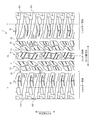
- FIG. 2 is a plan view showing a tread pattern of the pneumatic tire depicted in FIG. 1.
- FIG. 3 is an enlarged view showing a main part of the tread pattern shown in FIG.
- FIG. 4 is an enlarged view showing a second land portion of the tread pattern shown in FIG.
- FIG. 5 is an explanatory diagram showing a modification of the second land portion shown in FIG.
- FIG. 6 is an enlarged view showing a shoulder land portion of the tread pattern shown in FIG.
- FIG. 7 is an enlarged view showing the second land portion and the shoulder land portion described in FIG. 3.
- FIG. 8 is an explanatory diagram illustrating an example of a three-dimensional sipe.
- FIG. 9 is an explanatory diagram illustrating an example of a three-dimensional sipe.
- FIG. 10 is a chart showing the results of the performance test of the pneumatic tire according to the embodiment of the
- FIG. 1 is a sectional view in the tire meridian direction showing a pneumatic tire according to an embodiment of the present invention.
- the same figure has shown sectional drawing of the one-side area
- the figure shows a radial tire for a passenger car as an example of a pneumatic tire.
- the cross section in the tire meridian direction means a cross section when the tire is cut along a plane including the tire rotation axis (not shown).
- Reference sign CL denotes a tire equator plane, which is a plane that passes through the center point of the tire in the tire rotation axis direction and is perpendicular to the tire rotation axis.
- the tire width direction means a direction parallel to the tire rotation axis
- the tire radial direction means a direction perpendicular to the tire rotation axis.
- the pneumatic tire 1 has an annular structure centered on the tire rotation axis, and includes a pair of bead cores 11, a pair of bead fillers 12, 12, a carcass layer 13, a belt layer 14, and a tread rubber 15. And a pair of sidewall rubbers 16 and 16 and a pair of rim cushion rubbers 17 and 17 (see FIG. 1).
- the pair of bead cores 11 and 11 is an annular member formed by bundling a plurality of bead wires, and constitutes the core of the left and right bead portions.
- the pair of bead fillers 12 and 12 are disposed on the outer circumference in the tire radial direction of the pair of bead cores 11 and 11 to constitute a bead portion.
- the carcass layer 13 has a single layer structure composed of a single carcass ply or a multilayer structure formed by laminating a plurality of carcass plies, and is bridged in a toroidal shape between the left and right bead cores 11 and 11 to form a tire skeleton. Constitute. Further, both end portions of the carcass layer 13 are wound and locked outward in the tire width direction so as to wrap the bead core 11 and the bead filler 12.
- the carcass ply of the carcass layer 13 is formed by coating a plurality of carcass cords made of steel or an organic fiber material (for example, aramid, nylon, polyester, rayon, etc.) with a coat rubber and rolling it, and has an absolute value of 80 A carcass angle (inclination angle in the fiber direction of the carcass cord with respect to the tire circumferential direction) of [deg] or more and 95 [deg] or less.
- a carcass angle inclination angle in the fiber direction of the carcass cord with respect to the tire circumferential direction
- the belt layer 14 is formed by laminating a pair of cross belts 141 and 142 and a belt cover 143, and is arranged around the outer periphery of the carcass layer 13.
- the pair of cross belts 141 and 142 is formed by rolling a plurality of belt cords made of steel or organic fiber material with a coating rubber, and has an absolute value of a belt angle of 20 [deg] or more and 55 [deg] or less.
- the pair of cross belts 141 and 142 have belt angles with different signs from each other (inclination angle of the fiber direction of the belt cord with respect to the tire circumferential direction), and are laminated so that the fiber directions of the belt cords cross each other. (Cross ply structure).
- the belt cover 143 is formed by rolling a plurality of cords made of steel or organic fiber material covered with a coat rubber, and has a belt angle of 0 [deg] or more and 10 [deg] or less in absolute value. Further, the belt cover 143 is disposed so as to be laminated on the outer side in the tire radial direction of the cross belts 141 and 142.
- the tread rubber 15 is disposed on the outer circumference in the tire radial direction of the carcass layer 13 and the belt layer 14 to constitute a tread portion of the tire.
- the pair of side wall rubbers 16 and 16 are respectively arranged on the outer side in the tire width direction of the carcass layer 13 to constitute left and right side wall portions.
- the pair of rim cushion rubbers 17, 17 are respectively disposed on the inner side in the tire radial direction of the wound portions of the left and right bead cores 11, 11 and the carcass layer 13, and constitute the contact surfaces of the left and right bead portions with respect to the rim flange.
- FIG. 2 is a plan view showing a tread pattern of the pneumatic tire depicted in FIG. 1.
- the figure shows a tread pattern of an all-season tire.
- the tire circumferential direction refers to the direction around the tire rotation axis.
- Reference symbol T denotes a tire ground contact end.
- the pneumatic tire 1 includes a plurality of circumferential main grooves 21 and 22 extending in the tire circumferential direction, and a plurality of land portions 31 to 22 partitioned by the circumferential main grooves 21 and 22. 33 and a plurality of lug grooves 411, 412, 421, 422, 431, 432 arranged in the land portions 31 to 33 are provided in the tread portion.
- the circumferential main groove is a circumferential groove having a wear indicator indicating the end of wear, and generally has a groove width of 5.0 [mm] or more and a groove depth of 7.5 [mm] or more.
- the lug groove means a lateral groove having a groove width of 2.0 [mm] or more and a groove depth of 3.0 [mm] or more.
- the sipe described later is a cut formed in the land portion, and generally has a sipe width of less than 1.5 [mm].
- the groove width is measured as the maximum value of the distance between the left and right groove walls at the groove opening in a no-load state in which the tire is mounted on the specified rim and filled with the specified internal pressure.
- the groove width is based on the intersection of the tread surface and the extension line of the groove wall in a cross-sectional view in which the groove length direction is a normal direction. Measured.
- the groove width is measured with reference to the center line of the amplitude of the groove wall.
- the groove depth is measured as the maximum value of the distance from the tread surface to the groove bottom in an unloaded state in which the tire is mounted on the specified rim and filled with the specified internal pressure. Moreover, in the structure which a groove
- Specified rim means “Applied rim” defined in JATMA, “Design Rim” defined in TRA, or “Measuring Rim” defined in ETRTO.
- the specified internal pressure means “maximum air pressure” specified by JATMA, the maximum value of “TIRE LOAD LIMITS AT VARIOUS COLD INFLATIONLPRESSURES” specified by TRA, or “INFLATION PRESSURES” specified by ETRTO.
- the specified load means the “maximum load capacity” defined by JATMA, the maximum value of “TIRE LOAD LIMITS AT VARIOUS COLD INFUREATION PRESSURES” prescribed by TRA, or “LOAD CAPACITY” prescribed by ETRTO.
- the specified internal pressure is air pressure 180 [kPa]
- the specified load is 88 [%] of the maximum load capacity.
- the pneumatic tire 1 has a tread pattern that is symmetric with respect to a point on the tire equatorial plane CL.
- the four circumferential main grooves 21 and 22 are arranged symmetrically about the tire equatorial plane CL. Further, five rows of land portions 31 to 33 are defined by the four circumferential main grooves 21 and 22. Further, one land portion 31 is disposed on the tire equator plane CL.
- the present invention is not limited to this, and five or more circumferential main grooves may be arranged (not shown). Further, the circumferential main grooves 21 and 22 may be arranged asymmetrically about the tire equatorial plane CL (not shown). Further, the circumferential main groove may be disposed on the tire equatorial plane CL (not shown). For this reason, the land part 31 can be arrange
- the four circumferential main grooves 21, 22 have a straight shape as a whole, and the edge portions of the left and right land portions 31-33 protrude toward the circumferential main grooves 21, 22. Thereby, the groove wall of each circumferential direction main groove 21 and 22 is changing in the step shape toward the tire circumferential direction.
- the present invention is not limited to this, and the circumferential main grooves 21 and 22 may have a simple straight shape, or may have a zigzag shape or a wavy shape extending while being bent or curved in the tire circumferential direction. Good (not shown).
- the left and right circumferential main grooves 22 and 22 on the outermost side in the tire width direction are referred to as outermost circumferential main grooves.
- the tread portion center region and the tread portion shoulder region are defined with the left and right outermost circumferential main grooves 22 and 22 as boundaries.
- the land portion 33 that is the outermost in the tire width direction is defined as a shoulder land portion.
- the shoulder land portion 33 is a land portion on the outer side in the tire width direction defined by the outermost circumferential main groove 22 and has a tire ground contact end T on the tread surface.
- the land portion 32 in the second row from the outer side in the tire width direction is defined as the second land portion.
- the second land portion 32 is a land portion on the inner side in the tire width direction defined by the outermost circumferential main groove 22 and is adjacent to the shoulder land portion 33 with the outermost circumferential main groove 22 interposed therebetween.
- the land portion 31 that is closer to the tire equator plane CL than the second land portion 32 is defined as the center land portion.
- the center land portion 31 may be disposed on the tire equator plane CL (FIG. 2), or may be disposed at a position away from the tire equator plane CL (not shown).
- all the land portions 31 to 33 each have a plurality of lug grooves 411, 412; 421, 422; 431, 432 extending in the tire width direction.
- some lug grooves 411, 412; 421, 422; 431 are through lug grooves penetrating the corresponding land portions 31; 32; 33 in the tire width direction, and are arranged at predetermined intervals in the tire circumferential direction.
- all the land portions 31 to 33 are divided in the tire circumferential direction by the through lug grooves 411, 412; 421, 422; 431, and a block row composed of a plurality of blocks is formed.
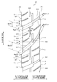
- FIG. 3 is an enlarged view showing a main part of the tread pattern shown in FIG. This figure shows an enlarged plan view of the ground contact surfaces of the center land portion and the shoulder land portion in one side region of the tire.
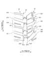
- FIG. 4 is an enlarged view showing a second land portion of the tread pattern shown in FIG.
- FIG. 5 is an explanatory diagram showing a modification of the second land portion shown in FIG.
- the second land portion 32 includes a plurality of types of through lug grooves 421 and 422 that penetrate the second land portion 32 in the tire width direction.
- a plurality of types of through lug grooves 421 and 422 are periodically arranged in the tire circumferential direction.
- the second land portion 32 is divided in the tire circumferential direction by these through lug grooves 421 and 422 to form one block row composed of a plurality of types of blocks 321 and 322.
- the plurality of types of blocks 321 and 322 have different shapes.
- a plurality of sets of block units each including the plurality of types of blocks 321 and 322 are repeatedly arranged over the entire circumference of the tire.
- the number of types of the above-described through lug grooves and blocks is set in the range of 2 or more and 3 or less.
- the pneumatic tire 1 has a pitch variation structure in which the pitch arrangement of the entire tread pattern is changed in the tire circumferential direction, and the circumferential lengths of the blocks of the land portions 31 to 33 are periodic in the tire circumferential direction. Is changing. For this reason, in the second land portion 32, the circumferential lengths of the blocks 321 and 322, which are a set of the above-described plural types, periodically change in the tire circumferential direction due to the pitch variation structure described above. Thereby, the pattern noise at the time of tire rolling is reduced, and the noise performance of the tire (particularly the in-vehicle noise performance) is improved.
- the crossing angles ⁇ 21 and ⁇ 22 of the first through lug groove 421 and the second through lug groove 422 adjacent to each other in the tire circumferential direction with respect to the outermost circumferential main groove 22 are different from each other.
- the first through lug groove 421 and the second through lug groove 422 intersect the outermost circumferential main groove 22 from the same direction in the tire circumferential direction at mutually different absolute crossing angles.
- the crossing angle ⁇ 21 of the first through lug groove 421 is larger than the crossing angle ⁇ 22 of the second through lug groove 422.
- crossing angles ⁇ 21 and ⁇ 22 preferably have a relationship of 10 [deg] ⁇ ⁇ 21 ⁇ 22 ⁇ 50 [deg], and have a relationship of 20 [deg] ⁇ ⁇ 21 ⁇ 22 ⁇ 40 [deg]. Is more preferable.
- the crossing angles ⁇ 21 and ⁇ 22 of the through lug groove are defined as the crossing angle between the groove center line of the outermost circumferential main groove and the extension line of the through lug groove. Measured as a load condition. Note that the crossing angle of the through lug grooves may be different from the overall inclination angle of the through lug grooves described later. For example, a configuration in which the entire groove of the through lug groove is bent or curved (see FIG. 4), or a configuration in which the through lug groove is partially bent at the opening with respect to the outermost circumferential main groove (not shown) can be employed.
- the adjacent through lug grooves 421 and 422 of the second land portion 32 open to the outermost circumferential main groove 22 with mutually different crossing angles ⁇ 21 and ⁇ 22, so that the blocks 321 and 322 are moved when running on a snowy road surface. Movement of the snow that has entered the communication portion between the through lug grooves 421 and 422 and the outermost circumferential main groove 22 is promoted. Thereby, the snow performance (particularly, steering stability and startability) of the tire is improved. In addition, the mud performance at the time of traveling on muddy ground or sandy land is improved by the same action.
- the opening widths Wo21 and Wo22 of the first through lug groove 421 and the second through lug groove 422 with respect to the outermost circumferential main groove 22 are different from each other. Therefore, the through lug grooves 421 and 422 having different opening widths Wo21 and Wo22 are alternately arranged in the tire circumferential direction. Thereby, the snow removal property on the snow road surface is improved.
- the opening widths Wo21 and Wo22 of the through lug grooves are the opening widths in the tread surface of the groove opening of the through lug groove with respect to the outermost circumferential main groove, and are notches and chamfers formed in the groove opening of the through lug groove. Is measured as a width including.
- the opening width Wo21 of the first through lug groove 421 having a large crossing angle ⁇ 21 with respect to the outermost circumferential main groove 22 is equal to the opening width Wo22 of the second through lug groove 422 having a small crossing angle ⁇ 22 with respect to the outermost circumferential main groove 22. Narrower than that. That is, the first through lug groove 421 having a larger intersection angle ⁇ 21 opens into the outermost circumferential main groove 22 with a narrower opening width Wo21 ( ⁇ Wo22). Thereby, the traction property (shearing force in snow) of the first through lug groove 421 having a large intersection angle ⁇ 21 is ensured.
- the second land portion 32 includes the chamfered portion 6 on one side of the groove opening on the outermost circumferential main groove 22 side of the through lug grooves 421 and 422, respectively.
- the size of the chamfered portion 6 formed in the opening of the first through lug groove 421 is smaller than the chamfered portion 6 formed in the opening of the second through lug groove 422.
- the opening width Wo21 of the first through lug groove 421 is relatively narrowed.
- the second land portion 32 includes two types of through lug grooves 421 and 422 and two types of blocks 321 and 322 that are divided into these through lug grooves 421 and 422, respectively.
- a plurality of sets of block units each including two types of blocks 321 and 322 are repeatedly arranged over the entire circumference of the tire (see FIG. 2).
- the two types of blocks 321 and 322 have different shapes and are alternately arranged in the tire circumferential direction.
- the entire grooves of the through lug grooves 421 and 422 of the second land portion 32 are inclined at a predetermined inclination angle (dimensional symbol omitted in the figure) with respect to the tire width direction.
- the absolute value of the inclination angle of the through lug grooves 421 and 422 is preferably in the range of 5 [deg] to 70 [deg], and preferably in the range of 20 [deg] to 48 [deg]. More preferred.
- the inclination angle of the entire groove with respect to the tire width direction of the first through lug groove 421 and the inclination angle of the entire groove with respect to the tire width direction of the second through lug groove 422 are different from each other.
- two types of through lug grooves 421 and 422 adjacent in the tire circumferential direction have mutually different inclination angles ⁇ 21 and ⁇ 22 (dimension symbols omitted in the figure).
- the two types of through lug grooves 421 and 422 are inclined in the same direction (in FIG.
- the difference between the inclination angles ⁇ 21 and ⁇ 22 is preferably in the range of 5 [deg] ⁇ ⁇ 21 ⁇ 22 ⁇ 40 [deg], and the range of 10 [deg] ⁇ ⁇ 21 ⁇ 22 ⁇ 20 [deg]. More preferably. As a result, the difference in inclination angle ⁇ 21 ⁇ 22 is optimized.
- the inclination angle of the through lug groove is measured as an angle formed by an imaginary line connecting the center point of the opening of the through lug groove with respect to the left and right circumferential main grooves and the tire rotation axis. Further, the inclination angle of the through lug groove in the shoulder land portion is measured as an angle formed by an imaginary line connecting the center point of the opening portion of the through lug groove with respect to the outermost circumferential main groove and the tire ground contact end and the tire rotation axis.
- the blocks 321 and 322 adjacent in the tire circumferential direction have different shapes. Specifically, the left and right edge portions on the circumferential main grooves 21 and 22 side of the blocks 321 and 322 have different circumferential lengths. Further, the edge portion on the tire equatorial plane CL side of one adjacent block 321 is long in the tire circumferential direction, and the edge portion on the tire ground contact end T side is short. Conversely, the edge portion on the tire equatorial plane CL side of the other block 322 is short in the tire circumferential direction, and the edge portion on the tire ground contact end T side is long in the tire circumferential direction.
- the edge portions of adjacent blocks 321 and 322 are tires so that the short edge portions protrude toward the circumferential main grooves 21 and 22 rather than the long edge portions. They are arranged offset from each other in the width direction.
- the two types of blocks 321 and 322 of the second land portion 32 have one circumferential narrow groove 323 and 324, respectively.
- the circumferential narrow grooves 323 and 324 have a bent shape having an amplitude in the tire width direction, and open to the adjacent through lug grooves 421 and 422 penetrating the blocks 321 and 322 in the tire circumferential direction, respectively.
- the blocks 321 and 322 are divided in the tire width direction, and the contact surface pressure of the blocks 321 and 322 at the time of tire contact is made uniform.
- the circumferential narrow grooves 323 and 324 have a bent shape, the edge component of the second land portion 32 is increased, and the snow performance of the tire is improved.
- the circumferential narrow grooves 323 and 324 are disposed in the center region in the tire width direction of the blocks 321 and 322 (region of 1/3 of the block width), and the treads of the blocks 321 and 322 are arranged approximately in the tire width direction. Divide equally. Further, the circumferential narrow grooves 323 and 324 have step-shaped bent portions having an amplitude in the tire width direction. Further, the bent portions of the circumferential narrow grooves 323 and 324 are arranged at the center portion in the tire circumferential direction of the blocks 321 and 322 (center portion when the blocks 321 and 322 are equally divided into three in the tire circumferential direction). Thereby, the rigidity in the tire circumferential direction of the blocks 321 and 322 is made uniform.
- the bent portions of the circumferential narrow grooves 323 and 324 are preferably inclined in the range of 50 [deg] to 70 [deg] with respect to the tire circumferential direction, and in the range of 55 [deg] to 65 [deg]. It is more preferable to incline.
- the groove width Ws of the circumferential narrow grooves 323 and 324 applies a specified internal pressure by attaching the tire to the specified rim, and also applies a load corresponding to the specified load by placing it perpendicular to the flat plate in a stationary state.
- the circumferential narrow grooves 323 and 324 are set so as not to be blocked by the contact surface between the tire and the flat plate.
- the groove width Ws of the circumferential narrow grooves 323 and 324 is set in a range of 1.5 [mm] ⁇ Ws ⁇ 6.0 [mm].
- the circumferential narrow grooves 323 and 324 are appropriately opened when the tire is in contact with the ground, the blocks 321 and 322 are divided, and the contact surface pressure of the blocks 321 and 322 is appropriately uniformized.
- the edge components of the blocks 321 and 322 are secured by the circumferential narrow grooves 323 and 324, and the traction of the tire is improved.
- the groove width Ws of the circumferential narrow grooves 323 and 324 is measured as the distance between the openings of the opposing groove wall surfaces when the tire is mounted on the specified rim to apply the specified internal pressure and the load is not loaded.
- the circumferential narrow grooves 323 and 324 adjacent to each other in the tire circumferential direction open at different positions with respect to the common through lug grooves 421 and 422. That is, the openings of the circumferential narrow grooves 323 and 324 that are opposed to each other with the through lug grooves 421 and 422 interposed therebetween are arranged with their positions shifted in the tire width direction. Accordingly, the openings of the adjacent circumferential narrow grooves 323 and 324 are arranged dispersed in the tire width direction. Thereby, the whole rigidity of the second land portion 32 is made uniform.
- the circumferential narrow grooves 323 and 324 have step-shaped bent portions, but the present invention is not limited to this, and the circumferential narrow grooves 323 and 324 are straight, arc-shaped, or wavy. It may have a shape (not shown).
- the through lug grooves 421 and 422 have a shape in which the groove width is increased toward the tire ground contact end T (see FIG. 2). Further, the groove widths Wg21_cl and Wg22_cl at the openings on the tire equatorial plane CL side of the through lug grooves 421 and 422 are narrower than the groove widths Wg21_t and Wg22_t at the opening on the tire ground contact end T side. Thereby, the rigidity of the region on the tire equatorial plane CL side of the blocks 321 and 322 of the second land portion 32 is ensured, and uneven wear of the blocks 321 and 322 is suppressed.
- the groove width of the through lug groove can be appropriately selected according to the tire size.
- the groove width of the through lug groove arranged in the second land portion is in the range of 2 [mm] to 10 [mm].
- one groove wall of the through lug grooves 421 and 422 of the second land portion 32 has a step-like bent portion in a tread plan view, and the other groove wall has a linear shape or an arc shape. Has a shape.
- the difference between the groove widths Wg21_cl and Wg21_t; Wg22_cl and Wg22_t of the left and right openings of the through lug grooves 421 and 422 is formed.
- the step-shaped bent portions on which the groove walls of the through lug grooves 421 and 422 are applied the edge components of the lug grooves 421 and 422 are increased, and the traction property is enhanced.
- the step-shaped bent portion includes a first groove wall portion, a second groove wall portion that is arranged offset in the tire circumferential direction with respect to the first groove wall portion, and the tire groove extending in the tire circumferential direction. It is defined by the circumferential groove wall portion connecting the one groove wall portion and the second groove wall portion.
- an angle formed by the wall surface of the circumferential groove wall portion and the tire circumferential direction is preferably in the range of 80 [deg] or more and 100 [deg] or less, and 85 [deg]. More preferably, it is in the range of 95 [deg] or less.
- one groove wall of the through lug grooves 411 and 412 is bent at the center portion of the second land portion 32, so that the left and right groove center lines of the bent portion are offset in the tire circumferential direction at the center portion of the second land portion 32.
- the offset amounts G1 and G2 in the tire circumferential direction of the groove center lines of the through lug grooves 421 and 422 are preferably in the range of 2.0 [mm] or more and 12.0 [mm] or less.
- the bending directions of the groove center lines of the adjacent through lug grooves 421 and 422 are opposite to each other with respect to the tire circumferential direction. For this reason, the edge portion of the block 322 sandwiched between the bent portions of the adjacent through lug grooves 421 and 422 is widened on the tire equatorial plane CL side and shortened on the tire ground contact end T side. Accordingly, the tire circumference of the portion of the block 322 that becomes narrow due to the difference in the inclination angle of the through lug grooves 421 and 422 (the portion on the tire equatorial plane CL side of the block 322 divided by the circumferential narrow groove 324) The length in the direction is ensured properly.
- one groove wall of the through lug grooves 421 and 422 of the second land portion 32 has a step-like bent portion in the tread plan view, and the other groove wall It has a linear shape or an arc shape.
- the present invention is not limited thereto, and as shown in the modification of FIG. 5, the left and right groove walls of the through lug grooves 421 and 422 of the second land portion 32 have step-like bent portions in the tread plan view, respectively. Also good.
- FIG. 6 is an enlarged view showing a shoulder land portion of the tread pattern shown in FIG.
- the shoulder land portion 33 includes a plurality of through lug grooves 431 that penetrate the shoulder land portion 33 in the tire width direction (see FIG. 2). As shown in FIG. 6, the shoulder land portion 33 includes a plurality of blocks 331 that are partitioned by adjacent through lug grooves 431.
- the through lug groove 431 passes through the shoulder land portion 33 in the tire width direction and opens to the circumferential main groove 22 and the tire ground contact end T.
- the through lug groove 431 has a shape in which the groove width is increased from the circumferential main groove 22 toward the tire ground contact end T.
- one groove wall of the through lug groove 431 has a step-like bent portion in a tread plan view, and the other groove wall has a linear shape or an arc shape.
- the present invention is not limited thereto, and the left and right groove walls of the through lug groove 431 may have a linear shape or an arc shape.
- the groove depth of the narrow portion on the circumferential main groove 22 side in the through lug groove 431 is in the range of 30% to 80% with respect to the groove depth of the wide portion on the tire ground contact end T side. It is preferable to have. Thereby, the snow removal effect
- the block 331 is divided into adjacent through lug grooves 431 and 431 and the outermost circumferential main groove 22, and is disposed on the tire ground contact end T.
- a plurality of blocks 331 are arranged in the tire circumferential direction to form a block row.
- Each block 331 includes one non-penetrating lug groove 432, which will be described later.
- the first through lug groove 421 and the second through lug groove 422 of the second land portion 32 and the through lug groove 431 of the shoulder land portion 33 are formed with respect to the outermost circumferential main groove 22. Opening at different positions in the tire circumferential direction. For this reason, the blocks 321 and 322 of the second land portion 32 and the blocks 331 of the shoulder land portion 33 are arranged in a staggered manner in the tire circumferential direction with the outermost circumferential main groove 22 interposed therebetween.
- the snow that has entered between the blocks 321 and 322 of the second land portion 32 and the block 331 of the shoulder land portion 33 is held and compacted during running on the snow road surface, so that traction on the snow road surface is achieved. This improves the snow performance (particularly, startability) of the tire.
- the shortest distance L2 in the tire circumferential direction from the opening to the outermost circumferential main groove 22 of the shoulder land portion 33 to the opening to the outermost circumferential main groove 22 of the through lug groove 431 of the shoulder land portion 33 is 0.40 ⁇ L2 / It is preferable to be in the range of L1 ⁇ 0.50. Thereby, the distance L2 of the penetration lug groove 431 of the shoulder land part 33 is ensured appropriately.
- the distances L1 and L2 of the through lug grooves are measured using the center point of the groove width of the through lug grooves 421, 422 and 431 with respect to the outermost circumferential main groove 22 as a measurement point.
- the first through lug groove 421 and the second through lug groove 422 of the second land portion 32 and the through lug groove 431 of the shoulder land portion 33 are directed in the tire width direction. Inclined in opposite directions. Further, the through lug grooves 421 and 422 in the left and right second land portions 32 and 32 are inclined in the same direction. Thereby, the traction property on the snow road surface at the time of vehicle turning increases, and the snow performance (particularly turning performance) of the tire is improved.
- the five rows of land portions 31 to 33 each include a plurality of through lug grooves 411, 412, 421, 422, and 431 that are inclined at a predetermined inclination angle with respect to the tire width direction.
- the through-lug grooves 411, 412, 431 of the center land portion 31 and the left and right shoulder land portions 33, 33 and the through-lug grooves 421, 422 of the left and right second land portions 32, 32 are directed in the tire width direction. They are inclined in opposite directions.
- the through lug grooves 411 and 412 of the center land portion 31 and the through lug grooves 431 of the shoulder land portion 33 are inclined in the same direction, and the through lug grooves 421 and 422 of the left and right second land portions 32 and 32 are provided. Are inclined in the same direction.
- channel of adjacent land part 31, 32; 32,33 is mutually reversed. Thereby, in the whole tread pattern, the penetration lug grooves 411, 412, 421, 422, and 431 are arranged in a zigzag shape toward the tire width direction. Thereby, the traction property on the snow road surface when the vehicle turns is further enhanced.
- channel 411, 412, 421, 422; 421,422,431 of adjacent land part 31,32; 32,33 are offset from each other in the tire circumferential direction. For this reason, the penetration lug grooves 411, 412, 421, 422; 421, 422, 431 of the adjacent land portions 31, 32; 32, 33 are not on the extension line of the groove center line and are discontinuously arranged with each other. Has been. Thereby, the traction property on the snow road surface is further enhanced.
- each block 331 of the shoulder land portion 33 includes one non-through lug groove 432.
- the non-penetrating lug groove 432 opens into the circumferential main groove 22 at one end portion and terminates in the ground contact surface of the shoulder land portion 33 at the other end portion. Further, one non-through lug groove 432 is disposed between the adjacent through lug grooves 431 and 431. Further, the maximum groove depth of the non-through lug groove 432 is shallower than the maximum groove depth of the through lug groove 431. Further, the non-penetrating lug groove 432 has a shape in which the groove width is gradually reduced from the circumferential main groove 22 toward the tire ground contact end T side.
- the groove width Wg32_cl of the end portion on the circumferential main groove 22 side in the non-through lug groove 432 and the groove width Wg32_t of the end portion on the tire ground contact end T side satisfy 1.10 ⁇ Wg32_cl / Wg32_t ⁇ 1.30. It is preferable to have a relationship. Thereby, the snow removal property of the non-through lug groove 432 is improved.
- the through lug grooves 421 and 422 of the second land portion 32 and the non-through lug grooves 432 of the shoulder land portion 33 are in the same position in the tire circumferential direction with respect to the outermost circumferential main groove 22. Open to. Accordingly, the opening of the non-through lug groove 432 of the shoulder land portion 33 is disposed substantially opposite to the opening of the through lug grooves 421 and 422 of the second land portion 32.
- the block 331 of the shoulder land portion 33 includes the non-penetrating lug groove 432, so that the block 331 of the shoulder land portion 33 is easily deformed when the tire rolls, and the snow held in the outermost circumferential main groove 22 Emissions are promoted.
- the shortest distance L3 in the tire circumferential direction from the opening to the outermost circumferential main groove 22 of the outer peripheral direction main groove 22 to the opening to the outermost circumferential main groove 22 of the non-through lug groove 432 of the shoulder land portion 33 is 0 ⁇ L3 / L1 It is preferable to be in the range of ⁇ 5.0. Thereby, the position of the opening part of the non-through lug groove 432 of the shoulder land part 33 is optimized.
- the groove width Wg31_cl of the opening with respect to the outermost circumferential main groove 22 of the through lug groove 431 and the groove width Wg32_cl of the opening with respect to the outermost circumferential main groove 22 of the non-through lug groove 432 have a relationship of Wg32_cl ⁇ Wg31_cl.
- the ratio Wg31_cl / Wg32_cl is preferably in the range of 1.3 ⁇ Wg31_cl / Wg32_cl ⁇ 2.0, and more preferably in the range of 1.6 ⁇ Wg31_cl / Wg32_cl ⁇ 1.8.
- FIG. 7 is an enlarged view showing the second land portion and the shoulder land portion shown in FIG. The figure shows the interrelationship between the edge portion of the second land portion 32 and the edge portion of the shoulder land portion 33 in the outermost circumferential main groove 22.
- the two types of blocks 321 and 322 adjacent to each other in the tire circumferential direction of the second land portion 32 have the edge portions on the outermost circumferential main groove 22 side mutually in the tire width direction. It is arranged with an offset. Therefore, the groove wall on the second land portion 32 side of the outermost circumferential main groove 22 has a shape that changes in a step shape in the tire width direction at the groove opening.
- the pair of edge portions on the outermost circumferential main groove 22 side of the block 331 partitioned by the non-penetrating lug groove 432 are offset from each other in the tire width direction. Arranged.
- the groove wall on the shoulder land portion 33 side of the outermost circumferential main groove 22 has a shape that changes stepwise in the tire width direction at the groove opening.
- the through lug grooves 421 and 422 of the second land portion 32 and the through lug grooves 431 of the shoulder land portion 33 are different from each other in the tire circumferential direction with respect to the outermost circumferential main groove 22. Open at. For this reason, the blocks 321 and 322 of the second land portion 32 and the blocks 331 of the shoulder land portion 33 are arranged in a staggered manner in the tire circumferential direction with the outermost circumferential main groove 22 interposed therebetween. Thus, the block row of the second land portion 32 and the block row of the shoulder land portion 33 are arranged with a phase shifted in the tire circumferential direction.
- the offset amount Ga2 of the edge portions of the two types of blocks 321 and 322 of the second land portion 32 and the offset amount Ga3 of the edge portions of the block 331 of the shoulder land portion 33 are caused.
- the distance De in the tire width direction of the opposing edge portions of the left and right land portions 32 and 33 across the outermost circumferential main groove 22 changes in a step shape as it goes in the tire circumferential direction.
- at least three types of distances De1 to De4 are formed. Thereby, the snow removal property of the outermost circumferential main groove 22 during traveling on the snow road surface is improved.
- De4 De_min
- the maximum value De_max and the minimum value De_min of the distance De preferably have a relationship of 1.20 ⁇ De_max / De_min ⁇ 1.80, and 1.50 ⁇ De_max / De_min ⁇ 1.70. It is more preferable to have a relationship. Thereby, the distance De of the tire width direction of the edge part which the right and left land parts 32 and 33 which pinch
- the offset amount Ga2 of the edge portion of the two types of blocks 321 and 322 of the second land portion 32 and the offset amount Ga3 of the edge portion of the block 331 of the shoulder land portion 33 are substantially the same.
- the ratio Ga2 / Ga3 is set in the range of 0.8 ⁇ Ga2 / Ga3 ⁇ 1.2.
- each land portion 31 to 33 includes a plurality of sipes 5.
- These sipes 5 are classified into two-dimensional sipes (so-called plane sipes) and three-dimensional sipes (so-called three-dimensional sipes). By these sipes 5, the edge components of the land portions 31 to 33 are secured, and the traction of the tire is improved.
- the two-dimensional sipe has a straight sipe wall surface in an arbitrary cross-sectional view (a cross-sectional view including a sipe width direction and a sipe depth direction) with the sipe length direction as a normal direction.
- the two-dimensional sipe only needs to have a straight shape in the above-described cross-sectional view, and can extend in the sipe length direction with a straight shape, a zigzag shape, a wave shape, an arc shape, or the like.
- the three-dimensional sipe has a bent sipe wall surface having an amplitude in the sipe width direction in both a cross-sectional view in which the sipe length direction is a normal direction and a cross-sectional view in which the sipe depth direction is a normal direction.
- the three-dimensional sipe has an action of reinforcing the rigidity of the land portion because the meshing force of the opposing sipe wall surfaces is stronger than that of the two-dimensional sipe.
- the three-dimensional sipe is sufficient if it has the above structure on the sipe wall surface, and the tread surface may have, for example, a straight shape, a zigzag shape, a wave shape, an arc shape, and the like. Examples of such a three-dimensional sipe include the following (see FIGS. 8 and 9).
- FIGS. 8 and 9 are explanatory diagrams illustrating an example of a three-dimensional sipe. These drawings show a perspective view of a three-dimensional sipe having a pyramidal sipe wall surface.
- the sipe wall surface has a structure in which a triangular pyramid and an inverted triangular pyramid are connected in the sipe length direction.
- the sipe wall surface has a zigzag shape on the tread surface side and a zigzag shape on the bottom side that are shifted in pitch in the tire width direction, and unevenness that faces each other between the zigzag shapes on the tread surface side and the bottom side.
- the sipe wall surface is an unevenness when viewed in the tire rotation direction among these unevennesses, between the convex bending point on the tread surface side and the concave bending point on the bottom side, the concave bending point on the tread surface side and the bottom side Between the convex bend points of the tread surface and the convex bend points on the tread surface side, and adjacent convex bend points that are adjacent to each other with ridge lines, and the ridge lines between the ridge lines in order in the tire width direction. It is formed by connecting in a plane.
- one sipe wall surface has an uneven surface in which convex triangular pyramids and inverted triangular pyramids are arranged alternately in the tire width direction, and the other sipe wall surface alternates between concave triangular pyramids and inverted triangular pyramids.
- the sipe wall surface has the uneven
- the sipe wall surface has a structure in which a plurality of prisms having a block shape are connected in the sipe depth direction and the sipe length direction while being inclined with respect to the sipe depth direction.
- the sipe wall surface has a zigzag shape on the tread surface.
- the sipe wall surface has a bent portion that is bent in the tire circumferential direction at two or more locations in the tire radial direction inside the block and continues in the tire width direction, and has an amplitude in the tire radial direction at the bent portion. It has a zigzag shape.
- the sipe wall surface makes the tire circumferential amplitude constant
- the inclination angle in the tire circumferential direction with respect to the normal direction of the tread surface is made smaller at the sipe bottom side part than the tread surface side part and bent.
- the amplitude of the tire in the tire radial direction is made larger at the sipe bottom side than at the tread surface side.
- the blocks 321 and 322 of the second land portion 32 each have a plurality of sipes 5, and these sipes 5 are all three-dimensional sipes.
- the sipe 5 terminates in the blocks 321 and 322 at one end portion, and opens at the edge portion of the block 321 at the other end portion and communicates with the circumferential main grooves 21 and 22.
- the sipe 5 extends in the tire width direction while inclining in the same direction as the through lug grooves 421 and 422 with respect to the tire circumferential direction.
- the sipe 5 and the through lug grooves 421 and 422 are arranged at equal intervals and parallel to each other in the tire circumferential direction, so that the blocks 321 and 322 are partitioned into rectangular and substantially equal width regions.
- the treads of some blocks 322 are on the tire equatorial plane CL side partitioned by the circumferential narrow grooves 323. It is relatively narrow in the area. For this reason, the number of sipes in this area is set to be smaller than the number of sipes in other areas. Thereby, the sipe density in the tread of each block 321 and 322 is equalized.
- the block 331 of the shoulder land portion 33 includes a plurality of sipes 5 and 5 ′.
- the sipe 5 arranged in parallel to the non-through lug groove 432 is a three-dimensional sipe, and the sipe 5 'arranged by extending the non-through lug groove 432 in the groove length direction is a two-dimensional sipe.
- none of these sipes 5 and 5 ′ are opened to the circumferential main groove 22 and the tire ground contact end T, and have a terminal portion inside the block 331.
- the through lug groove 431 that partitions the block 331, the non-through lug groove 432 inside the block 331, and the three-dimensional sipe 5 are arranged at equal intervals and in parallel in the tire circumferential direction, so that the block 331 is It is divided into rectangular and substantially equal width regions.
- the second land portion 32 includes a first through lug groove 421 and a second through lug groove 422 that penetrate the second land portion 32 in the tire width direction and are arranged adjacent to each other in the tire circumferential direction. Further, the intersection angles ⁇ 21 and ⁇ 22 of the first through lug groove 421 and the second through lug groove 422 with respect to the outermost circumferential main groove 22 are different from each other (see FIG. 3).
- the first through lug grooves 421 and the second through lug grooves 422 of the second land portion 32 are alternately arranged in the tire circumferential direction (see FIG. 4). Therefore, a plurality of sets of groove units each including two types of through lug grooves 421 and 422 are continuously arranged in the tire circumferential direction. Thereby, there exists an advantage by which the improvement effect of the snow performance by two types of through lug grooves 421 and 422 is obtained effectively.
- the first through lug groove 421 and the second through lug groove 422 intersect with the outermost circumferential main groove 22 from the same direction in the tire circumferential direction (see FIG. 3). Therefore, the two types of through lug grooves 421 and 422 have crossing angles ⁇ 21 and ⁇ 22 having the same sign.
- the block is easily deformed, and snow drainage is improved.
- the opening width Wo21 (the opening width of the lug groove including the chamfered portion 6 in FIG. 4) with respect to the outermost circumferential main groove 22 of the first through lug groove 421 having a large intersection angle ⁇ 21 is
- the second lug groove 422 having a small crossing angle ⁇ 22 is narrower than the opening width Wo22 with respect to the outermost circumferential main groove 22 (see FIG. 4).
- the crossing angle of the lug groove with respect to the circumferential main groove increases, the traction (shear force in snow) in the lug groove tends to decrease. Therefore, there is an advantage that traction is ensured by narrowing the opening width Wo21 of the first through lug groove 421 having a large crossing angle ⁇ 21.
- At least one groove wall of the first through lug groove 421 has a step-like bent portion that bends in the tire circumferential direction in a tread plan view.
- the first through lug groove 421 and the second through lug groove 422 have a shape in which the groove width is widened toward the tire ground contact end T side (see FIG. 4).
- the second land portion 32 includes a plurality of blocks 321 and 322 that are partitioned into a plurality of through lug grooves 421 and 422 (see FIG. 3).
- the blocks 321 and 322 adjacent to each other in the tire circumferential direction have different shapes. With such a configuration, there is an advantage that the block is easily deformed and the snow drainage is improved.
- the inclination angle of the whole groove with respect to the tire width direction of the first through lug groove 421 (the imaginary line connecting the openings to the left and right circumferential main grooves of the through lug groove and the tire width direction)
- the dimension of the second through lug groove 422 and the inclination angle of the entire groove with respect to the tire width direction are different from each other.
- the shoulder land portion 33 includes a through lug groove 431 that penetrates the shoulder land portion 33 in the tire width direction (see FIG. 2). Further, the first through lug groove 421 and the second through lug groove 422 of the second land portion 32 and the through lug groove 431 of the shoulder land portion 33 become the outermost circumferential main groove 22 at positions different from each other in the tire circumferential direction. It opens with respect to it (refer FIG. 3).
- the blocks 321 and 322 of the second land portion 32 and the blocks 331 of the shoulder land portion 33 are arranged in a staggered manner in the tire circumferential direction with the outermost circumferential main groove 22 interposed therebetween.
- the shoulder land portion 33 includes a through lug groove 431 that penetrates the shoulder land portion 33 in the tire width direction (see FIG. 2). Further, the first through lug groove 421 and the second through lug groove 422 of the second land portion 32 and the through lug groove 431 of the shoulder land portion 33 are inclined in opposite directions toward the tire width direction (FIG. 3). reference). As a result, the traction on the snow road surface when the vehicle turns is increased, and the snow performance (particularly the turning performance) of the tire is advantageously improved.
- At least one groove wall of the through lug groove 431 of the shoulder land portion 33 has a step-like bent portion bent in the tire circumferential direction in a tread plan view (see FIG. 3).
- the shoulder land portion 33 opens to the outermost circumferential main groove 22 at one end portion, and terminates in the ground contact surface of the shoulder land portion 33 at the other end portion.
- a lug groove 432 is provided (see FIG. 2). Further, the first through lug groove 421 or the second through lug groove 422 of the second land portion 32 and the non-through lug groove 432 of the shoulder land portion 33 are located at the same position in the tire circumferential direction with respect to the outermost circumferential main groove 22. (See FIG. 3).
- the block 331 of the shoulder land portion 33 includes the non-penetrating lug groove 432, so that the block 331 of the shoulder land portion 33 is easily deformed when the tire rolls, and the through lug groove 421 of the second land portion 32. 422 and the outermost circumferential main groove 22 have an advantage of facilitating the discharge of snow held.
- the groove width Wg32_cl has a relationship of Wg32_cl ⁇ Wg31_cl (see FIG. 6).
- the second land portion 32 includes two types of blocks 321 and 322 that are divided into adjacent first through lug grooves 421 and second through lug grooves 422 (see FIG. 3). Further, the two types of blocks 321 and 322 of the second land portion 32 are arranged with the edge portions on the outermost circumferential direction main groove 22 side offset from each other in the tire width direction.
- the shoulder land portion 33 includes a through lug groove 431 that penetrates the shoulder land portion 33 in the tire width direction, and a block 331 that is partitioned into adjacent through lug grooves 431 and 431.
- the block 331 of the shoulder land portion 33 has a non-through lug groove 432 that opens into the outermost circumferential main groove 22 at one end portion and terminates in the ground contact surface of the shoulder land portion 33 at the other end portion.
- the pair of edge portions on the outermost circumferential main groove 22 side of the block 321 of the shoulder land portion 33 partitioned by the non-penetrating lug groove 432 are arranged offset from each other in the tire width direction.
- the outermost circumferential main groove is caused by the offset amount Ga2 of the edge portion of the two types of blocks 321 and 322 of the second land portion 32 and the offset amount Ga3 of the edge portion of the block 331 of the shoulder land portion 33.
- the distance De between the 22 opposing groove walls changes stepwise as it goes in the tire circumferential direction.
- the distance De in the tire width direction between the edge portions of the two types of blocks 321 and 322 of the second land portion 32 and the pair of edge portions of the block 331 of the shoulder land portion 33 (see FIG. 7).
- the maximum change amount De_max / De_min of the distance De is ensured by 1.20 ⁇ De_max / De_min, and the effect of improving the snow discharge performance of the outermost circumferential main groove 22 is ensured. Further, due to De_max / De_min ⁇ 1.80, uneven wear at the edge portion of the block due to the maximum change amount De_max / De_min of the distance De being suppressed.
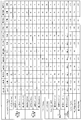
- FIG. 10 is a chart showing the results of the performance test of the pneumatic tire according to the embodiment of the present invention.
- test tire having a tire size of 265 / 65R17 112H is assembled to a rim having a rim size of 17 ⁇ 8 J, and an air pressure of 230 [kPa] and a maximum load specified by JATMA are applied to the test tire.
- the test tire is mounted on all wheels of a four-wheel drive RV (Recreational Vehicle) vehicle having a displacement of 3.5 [L], which is a test vehicle.
- RV Recreational Vehicle
- test vehicle runs on a predetermined handling course on a snowy road at a speed of 40 [km / h], and the test driver performs a sensory evaluation on the driving stability.
- This evaluation is performed by index evaluation using the conventional example as a reference (100), and the larger the value, the better.
- test vehicle starts from a stop on the snow road, and the test driver performs a sensory evaluation on the start performance.
- This evaluation is performed by index evaluation using the conventional example as a reference (100), and the larger the value, the better.
- the test tires of Examples 1 to 10 basically have the configuration shown in FIGS. 1 and 2 and have four circumferential main grooves 21 and 22 and five rows of land portions 31 to 33.
- Each of the land portions 31 to 33 includes a plurality of through lug grooves 411, 412, 421, 422, and 431 bent in a Z shape or a crank shape, and a block row defined by these through lug grooves, respectively.
- the opening part with respect to the outermost circumferential direction main groove 22 of the through lug groove 421,422 of the second land part 32 and the opening part with respect to the outermost circumferential direction main groove 22 of the through lug groove 431 of the shoulder land part 33 are offset in the tire circumferential direction.
- the block rows of the second land portion 32 and the block rows of the shoulder land portion 33 are arranged in a staggered manner in the tire circumferential direction (see FIG. 3).
- the groove depth of the circumferential main groove 22 is 10.0 [mm]
- the maximum groove depth of the through lug grooves 411, 412, 421, 422, and 431 is 7.0 [mm].
- the groove width Ws of the circumferential narrow grooves 323 and 324 of the second land portion 32 is 2.0 [mm]
- the groove depth is 5.0 [mm].
- “2nd” indicates the left and right second land portions 32 and 32
- “SH” indicates the left and right shoulder land portions 33 and 33.
- the through lug groove in the second land portion has a constant crossing angle, groove width, and opening width in the test tire of Example 1, and each through lug groove is linear or arcuate. It has a groove shape.
- the penetrating lug groove in the second land portion and the penetrating lug groove in the shoulder land portion face each other at the outermost circumferential main groove, and the block row in the second land portion and the block row in the shoulder land portion are in the tire circumference. Arranged in parallel in the direction.
- test tires of Examples 1 to 10 have improved on-snow handling stability and on-snow start performance.
Landscapes
- Engineering & Computer Science (AREA)
- Mechanical Engineering (AREA)
- Tires In General (AREA)
Abstract
Description
図1は、この発明の実施の形態にかかる空気入りタイヤを示すタイヤ子午線方向の断面図である。同図は、タイヤ径方向の片側領域の断面図を示している。また、同図は、空気入りタイヤの一例として、乗用車用ラジアルタイヤを示している。
図2は、図1に記載した空気入りタイヤのトレッドパターンを示す平面図である。同図は、オールシーズン用タイヤのトレッドパターンを示している。同図において、タイヤ周方向とは、タイヤ回転軸周りの方向をいう。また、符号Tは、タイヤ接地端である。
図3は、図2に記載したトレッドパターンの要部を示す拡大図である。同図は、タイヤの片側領域におけるセンター陸部およびショルダー陸部の接地面の拡大平面図を示している。図4は、図2に記載したトレッドパターンのセカンド陸部を示す拡大図である。図5は、図4に記載したセカンド陸部の変形例を示す説明図である。これらの図は、単体の陸部の拡大平面図を示している。
図6は、図2に記載したトレッドパターンのショルダー陸部を示す拡大図である。
図2および図4~図6に示すように、各陸部31~33は、複数のサイプ5をそれぞれ備える。これらのサイプ5は、二次元サイプ(いわゆる平面サイプ)および三次元サイプ(いわゆる立体サイプ)に分類される。これらのサイプ5により、陸部31~33のエッジ成分が確保されて、タイヤのトラクション性が向上する。
以上説明したように、この空気入りタイヤ1では、タイヤ周方向に延在する4本以上の周方向主溝21、22と、周方向主溝21、22に区画されて成る5列以上の陸部31~33とを備える(図2参照)。また、セカンド陸部32が、セカンド陸部32をタイヤ幅方向に貫通すると共にタイヤ周方向に隣り合って配列された第一貫通ラグ溝421および第二貫通ラグ溝422を備える。また、第一貫通ラグ溝421および第二貫通ラグ溝422の最外周方向主溝22に対する交差角φ21、φ22が、相互に異なる(図3参照)。
Claims (15)
- タイヤ周方向に延在する4本以上の周方向主溝と、前記周方向主溝に区画されて成る5列以上の陸部とを備える空気入りタイヤであって、
タイヤ幅方向最も外側にある左右の前記周方向主溝を最外周方向主溝として定義し、タイヤ幅方向最も外側にある左右の前記陸部をショルダー陸部として定義し、タイヤ幅方向外側から2列目にある左右の前記陸部をセカンド陸部として定義するときに、
前記セカンド陸部が、前記セカンド陸部をタイヤ幅方向に貫通すると共にタイヤ周方向に隣り合って配列された第一貫通ラグ溝および第二貫通ラグ溝を備え、且つ、
前記第一貫通ラグ溝および前記第二貫通ラグ溝の前記最外周方向主溝に対する交差角が、相互に異なることを特徴とする空気入りタイヤ。 - 前記第一貫通ラグ溝および前記第二貫通ラグ溝が、タイヤ周方向に交互に配列される請求項1に記載の空気入りタイヤ。
- 前記第一貫通ラグ溝および前記第二貫通ラグ溝が、前記最外周方向主溝に対してタイヤ周方向の同一方向から交差する請求項1または2に記載の空気入りタイヤ。
- 大きな前記交差角をもつ前記第一貫通ラグ溝の前記最外周方向主溝に対する開口幅が、小さな前記交差角をもつ前記第二貫通ラグ溝の前記最外周方向主溝に対する開口幅よりも狭い請求項1~3のいずれか一つに記載の空気入りタイヤ。
- 前記第一貫通ラグ溝の少なくとも一方の溝壁が、トレッド平面視にてタイヤ周方向に屈曲するステップ状の屈曲部を有する請求項1~4のいずれか一つに記載の空気入りタイヤ。
- 前記第一貫通ラグ溝および前記第二貫通ラグ溝が、タイヤ接地端側に向かって溝幅を拡幅した形状を有する請求項1~5のいずれか一つに記載の空気入りタイヤ。
- 前記セカンド陸部が、前記第一貫通ラグ溝および前記第二貫通ラグ溝に区画されて成るブロックを備え、且つ、
タイヤ周方向に隣り合う前記ブロックが、相互に異なる形状を有する請求項1~6のいずれか1つに記載の空気入りタイヤ。 - 前記第一貫通ラグ溝のタイヤ幅方向に対する溝全体の傾斜角と前記第二貫通ラグ溝のタイヤ幅方向に対する溝全体の傾斜角とが、相互に異なる請求項1~7のいずれか一つに記載の空気入りタイヤ。
- 前記ショルダー陸部が、前記ショルダー陸部をタイヤ幅方向に貫通する貫通ラグ溝を備え、且つ、
前記セカンド陸部の前記第一貫通ラグ溝および前記第二貫通ラグ溝と、前記ショルダー陸部の前記貫通ラグ溝とが、タイヤ周方向の相互に異なる位置で前記最外周方向主溝に対して開口する請求項1~8のいずれか一つに記載の空気入りタイヤ。 - 前記ショルダー陸部が、前記ショルダー陸部をタイヤ幅方向に貫通する貫通ラグ溝を備え、且つ、
前記セカンド陸部の前記第一貫通ラグ溝および前記第二貫通ラグ溝と、前記ショルダー陸部の前記貫通ラグ溝とが、タイヤ幅方向に向かって相互に逆方向に傾斜する請求項1~9のいずれか一つに記載の空気入りタイヤ。 - 前記ショルダー陸部の前記貫通ラグ溝の少なくとも一方の溝壁が、トレッド平面視にてタイヤ周方向に屈曲するステップ状の屈曲部を有する請求項1~10のいずれか一つに記載の空気入りタイヤ。
- 前記ショルダー陸部が、一方の端部にて前記最外周方向主溝に開口すると共に他方の端部にて前記ショルダー陸部の接地面内で終端する非貫通ラグ溝を備え、
前記セカンド陸部の前記第一貫通ラグ溝あるいは前記第二貫通ラグ溝と、前記ショルダー陸部の前記非貫通ラグ溝とが、前記最外周方向主溝に対してタイヤ周方向の同位置に開口する請求項1~11のいずれか一つに記載の空気入りタイヤ。 - 前記ショルダー陸部の前記貫通ラグ溝の前記最外周方向主溝に対する開口部の溝幅Wg31_clと、前記非貫通ラグ溝の前記最外周方向主溝に対する開口部の溝幅Wg32_clとが、Wg32_cl<Wg31_clの関係を有する請求項12に記載の空気入りタイヤ。
- 前記セカンド陸部が、隣り合う前記第一貫通ラグ溝および前記第二貫通ラグ溝に区画されて成る2種類のブロックを備え、
前記セカンド陸部の前記2種類のブロックが、前記最外周方向主溝側のエッジ部をタイヤ幅方向に相互にオフセットさせて配置され、
前記ショルダー陸部が、前記ショルダー陸部をタイヤ幅方向に貫通する貫通ラグ溝と、隣り合う前記貫通ラグ溝に区画されて成るブロックとを備え、
前記ショルダー陸部の前記ブロックが、一方の端部にて前記最外周方向主溝に開口すると共に他方の端部にて前記ショルダー陸部の接地面内で終端する非貫通ラグ溝を有し、且つ、
前記非貫通ラグ溝に区画された前記ショルダー陸部の前記ブロックの前記最外周方向主溝側の一対のエッジ部が、タイヤ幅方向に相互にオフセットして配置される請求項1~13のいずれか一つに記載の空気入りタイヤ。 - 前記セカンド陸部の前記2種類のブロックのエッジ部と、前記ショルダー陸部の前記ブロックの前記一対のエッジ部とのタイヤ幅方向の距離Deを定義し、
距離Deの最大値De_maxと最小値De_minとが、1.20≦De_max/De_min≦1.80の関係を有する請求項14に記載の空気入りタイヤ。
Priority Applications (7)
| Application Number | Priority Date | Filing Date | Title |
|---|---|---|---|
| DE112017000746.1T DE112017000746T5 (de) | 2016-02-10 | 2017-02-09 | Luftreifen |
| US16/075,526 US11427035B2 (en) | 2016-02-10 | 2017-02-09 | Pneumatic tire |
| CN201780010570.0A CN108602390B (zh) | 2016-02-10 | 2017-02-09 | 充气轮胎 |
| RU2018128957A RU2708830C1 (ru) | 2016-02-10 | 2017-02-09 | Пневматическая шина |
| KR1020187022365A KR102120870B1 (ko) | 2016-02-10 | 2017-02-09 | 공기입 타이어 |
| AU2017216717A AU2017216717B2 (en) | 2016-02-10 | 2017-02-09 | Pneumatic tire |
| AU2020200025A AU2020200025B2 (en) | 2016-02-10 | 2020-01-02 | Pneumatic tire |
Applications Claiming Priority (2)
| Application Number | Priority Date | Filing Date | Title |
|---|---|---|---|
| JP2016023544A JP6288119B2 (ja) | 2016-02-10 | 2016-02-10 | 空気入りタイヤ |
| JP2016-023544 | 2016-02-10 |
Publications (1)
| Publication Number | Publication Date |
|---|---|
| WO2017138622A1 true WO2017138622A1 (ja) | 2017-08-17 |
Family
ID=59563509
Family Applications (1)
| Application Number | Title | Priority Date | Filing Date |
|---|---|---|---|
| PCT/JP2017/004822 Ceased WO2017138622A1 (ja) | 2016-02-10 | 2017-02-09 | 空気入りタイヤ |
Country Status (8)
| Country | Link |
|---|---|
| US (1) | US11427035B2 (ja) |
| JP (1) | JP6288119B2 (ja) |
| KR (1) | KR102120870B1 (ja) |
| CN (1) | CN108602390B (ja) |
| AU (2) | AU2017216717B2 (ja) |
| DE (1) | DE112017000746T5 (ja) |
| RU (1) | RU2708830C1 (ja) |
| WO (1) | WO2017138622A1 (ja) |
Families Citing this family (7)
| Publication number | Priority date | Publication date | Assignee | Title |
|---|---|---|---|---|
| JP6809988B2 (ja) * | 2017-06-15 | 2021-01-06 | 株式会社ブリヂストン | タイヤ |
| JP6927807B2 (ja) | 2017-08-31 | 2021-09-01 | Toyo Tire株式会社 | 空気入りタイヤ |
| TWI684539B (zh) * | 2019-03-06 | 2020-02-11 | 特耐橡膠工業有限公司 | 具有胎面排氣溝之輪胎及其成型模具 |
| CN110576707B (zh) * | 2019-09-18 | 2024-05-10 | 安徽佳通乘用子午线轮胎有限公司 | 一种低噪音的全路况轮胎 |
| JP7170769B2 (ja) * | 2021-03-18 | 2022-11-14 | Toyo Tire株式会社 | 空気入りタイヤ |
| CN113043796A (zh) * | 2021-05-08 | 2021-06-29 | 万力轮胎股份有限公司 | 一种高性能轮胎 |
| EP4357158B1 (en) * | 2022-10-21 | 2026-02-18 | Sumitomo Rubber Industries, Ltd. | Pneumatic tire |
Citations (3)
| Publication number | Priority date | Publication date | Assignee | Title |
|---|---|---|---|---|
| JP2003118321A (ja) * | 2001-10-12 | 2003-04-23 | Sumitomo Rubber Ind Ltd | 重荷重用タイヤ |
| JP2010208419A (ja) * | 2009-03-09 | 2010-09-24 | Bridgestone Corp | 空気入りタイヤ |
| JP2013119282A (ja) * | 2011-12-06 | 2013-06-17 | Yokohama Rubber Co Ltd:The | 空気入りタイヤ |
Family Cites Families (15)
| Publication number | Priority date | Publication date | Assignee | Title |
|---|---|---|---|---|
| JP3397226B2 (ja) | 1994-11-28 | 2003-04-14 | 横浜ゴム株式会社 | 空気入りタイヤ |
| JP3718021B2 (ja) | 1997-02-21 | 2005-11-16 | 株式会社ブリヂストン | オール・シーズン乗用車用空気入りラジアル・タイヤ |
| JP3894743B2 (ja) | 2001-04-05 | 2007-03-22 | 横浜ゴム株式会社 | 空気入りタイヤ |
| JP3682269B2 (ja) * | 2002-05-09 | 2005-08-10 | 住友ゴム工業株式会社 | 空気入りタイヤ |
| JP4316452B2 (ja) | 2003-09-29 | 2009-08-19 | 横浜ゴム株式会社 | 空気入りタイヤ |
| JP4468006B2 (ja) * | 2004-02-25 | 2010-05-26 | 住友ゴム工業株式会社 | 空気入りタイヤ |
| JP4738276B2 (ja) | 2006-08-03 | 2011-08-03 | 株式会社ブリヂストン | 空気入りタイヤ |
| US20080271826A1 (en) * | 2007-05-03 | 2008-11-06 | Paul Bryan Maxwell | Pnuematic tire |
| US9789734B2 (en) * | 2011-03-28 | 2017-10-17 | Bridgestone Corporation | Pneumatic tire |
| EP2620299B1 (en) * | 2012-01-26 | 2015-06-17 | Sumitomo Rubber Industries, Ltd. | Pneumatic tire |
| CN203418936U (zh) * | 2013-06-28 | 2014-02-05 | 建大橡胶(中国)有限公司 | 一种suv雪地轮胎 |
| JP6330568B2 (ja) | 2014-08-11 | 2018-05-30 | 横浜ゴム株式会社 | 空気入りタイヤ |
| JP6084195B2 (ja) * | 2014-11-27 | 2017-02-22 | 住友ゴム工業株式会社 | 空気入りタイヤ |
| JP6065033B2 (ja) | 2015-01-29 | 2017-01-25 | 横浜ゴム株式会社 | 空気入りタイヤ |
| JP6517598B2 (ja) * | 2015-06-15 | 2019-05-22 | Toyo Tire株式会社 | 空気入りタイヤ |
-
2016
- 2016-02-10 JP JP2016023544A patent/JP6288119B2/ja active Active
-
2017
- 2017-02-09 WO PCT/JP2017/004822 patent/WO2017138622A1/ja not_active Ceased
- 2017-02-09 KR KR1020187022365A patent/KR102120870B1/ko active Active
- 2017-02-09 US US16/075,526 patent/US11427035B2/en active Active
- 2017-02-09 RU RU2018128957A patent/RU2708830C1/ru active
- 2017-02-09 AU AU2017216717A patent/AU2017216717B2/en active Active
- 2017-02-09 DE DE112017000746.1T patent/DE112017000746T5/de active Pending
- 2017-02-09 CN CN201780010570.0A patent/CN108602390B/zh active Active
-
2020
- 2020-01-02 AU AU2020200025A patent/AU2020200025B2/en active Active
Patent Citations (3)
| Publication number | Priority date | Publication date | Assignee | Title |
|---|---|---|---|---|
| JP2003118321A (ja) * | 2001-10-12 | 2003-04-23 | Sumitomo Rubber Ind Ltd | 重荷重用タイヤ |
| JP2010208419A (ja) * | 2009-03-09 | 2010-09-24 | Bridgestone Corp | 空気入りタイヤ |
| JP2013119282A (ja) * | 2011-12-06 | 2013-06-17 | Yokohama Rubber Co Ltd:The | 空気入りタイヤ |
Also Published As
| Publication number | Publication date |
|---|---|
| JP2017140926A (ja) | 2017-08-17 |
| AU2017216717B2 (en) | 2020-01-23 |
| KR20180099868A (ko) | 2018-09-05 |
| RU2708830C1 (ru) | 2019-12-11 |
| AU2020200025A1 (en) | 2020-01-30 |
| US20190039420A1 (en) | 2019-02-07 |
| AU2017216717A1 (en) | 2018-08-23 |
| AU2020200025B2 (en) | 2022-01-06 |
| JP6288119B2 (ja) | 2018-03-07 |
| KR102120870B1 (ko) | 2020-06-09 |
| DE112017000746T5 (de) | 2018-10-25 |
| CN108602390B (zh) | 2020-07-28 |
| CN108602390A (zh) | 2018-09-28 |
| US11427035B2 (en) | 2022-08-30 |
Similar Documents
| Publication | Publication Date | Title |
|---|---|---|
| JP6330568B2 (ja) | 空気入りタイヤ | |
| JP6206517B2 (ja) | 空気入りタイヤ | |
| JP5983788B2 (ja) | 空気入りタイヤ | |
| JP6288119B2 (ja) | 空気入りタイヤ | |
| JP5920532B2 (ja) | 空気入りタイヤ | |
| JP5942795B2 (ja) | 空気入りタイヤ | |
| JP6107843B2 (ja) | 空気入りタイヤ | |
| US11285759B2 (en) | Pneumatic tire | |
| WO2013136947A1 (ja) | 空気入りタイヤ | |
| WO2016056597A1 (ja) | 空気入りタイヤ | |
| US20200001654A1 (en) | Pneumatic Tire | |
| WO2017043227A1 (ja) | 空気入りタイヤ | |
| CN109414963B (zh) | 充气轮胎 | |
| JP2020006878A (ja) | 空気入りタイヤ | |
| JP2017136954A (ja) | 空気入りタイヤ | |
| JP2021008161A (ja) | 空気入りタイヤ |
Legal Events
| Date | Code | Title | Description |
|---|---|---|---|
| 121 | Ep: the epo has been informed by wipo that ep was designated in this application |
Ref document number: 17750343 Country of ref document: EP Kind code of ref document: A1 |
|
| ENP | Entry into the national phase |
Ref document number: 20187022365 Country of ref document: KR Kind code of ref document: A |
|
| WWE | Wipo information: entry into national phase |
Ref document number: 1020187022365 Country of ref document: KR |
|
| WWE | Wipo information: entry into national phase |
Ref document number: 112017000746 Country of ref document: DE |
|
| ENP | Entry into the national phase |
Ref document number: 2017216717 Country of ref document: AU Date of ref document: 20170209 Kind code of ref document: A |
|
| 122 | Ep: pct application non-entry in european phase |
Ref document number: 17750343 Country of ref document: EP Kind code of ref document: A1 |