WO2017138108A1 - 空気調和装置 - Google Patents
空気調和装置 Download PDFInfo
- Publication number
- WO2017138108A1 WO2017138108A1 PCT/JP2016/053942 JP2016053942W WO2017138108A1 WO 2017138108 A1 WO2017138108 A1 WO 2017138108A1 JP 2016053942 W JP2016053942 W JP 2016053942W WO 2017138108 A1 WO2017138108 A1 WO 2017138108A1
- Authority
- WO
- WIPO (PCT)
- Prior art keywords
- source side
- heat source
- refrigerant
- heat exchanger
- indoor
- Prior art date
Links
Images


Classifications
-
- F—MECHANICAL ENGINEERING; LIGHTING; HEATING; WEAPONS; BLASTING
- F25—REFRIGERATION OR COOLING; COMBINED HEATING AND REFRIGERATION SYSTEMS; HEAT PUMP SYSTEMS; MANUFACTURE OR STORAGE OF ICE; LIQUEFACTION SOLIDIFICATION OF GASES
- F25B—REFRIGERATION MACHINES, PLANTS OR SYSTEMS; COMBINED HEATING AND REFRIGERATION SYSTEMS; HEAT PUMP SYSTEMS
- F25B47/00—Arrangements for preventing or removing deposits or corrosion, not provided for in another subclass
- F25B47/02—Defrosting cycles
-
- F—MECHANICAL ENGINEERING; LIGHTING; HEATING; WEAPONS; BLASTING
- F24—HEATING; RANGES; VENTILATING
- F24F—AIR-CONDITIONING; AIR-HUMIDIFICATION; VENTILATION; USE OF AIR CURRENTS FOR SCREENING
- F24F11/00—Control or safety arrangements
- F24F11/89—Arrangement or mounting of control or safety devices
-
- F—MECHANICAL ENGINEERING; LIGHTING; HEATING; WEAPONS; BLASTING
- F25—REFRIGERATION OR COOLING; COMBINED HEATING AND REFRIGERATION SYSTEMS; HEAT PUMP SYSTEMS; MANUFACTURE OR STORAGE OF ICE; LIQUEFACTION SOLIDIFICATION OF GASES
- F25B—REFRIGERATION MACHINES, PLANTS OR SYSTEMS; COMBINED HEATING AND REFRIGERATION SYSTEMS; HEAT PUMP SYSTEMS
- F25B1/00—Compression machines, plants or systems with non-reversible cycle
-
- F—MECHANICAL ENGINEERING; LIGHTING; HEATING; WEAPONS; BLASTING
- F25—REFRIGERATION OR COOLING; COMBINED HEATING AND REFRIGERATION SYSTEMS; HEAT PUMP SYSTEMS; MANUFACTURE OR STORAGE OF ICE; LIQUEFACTION SOLIDIFICATION OF GASES
- F25B—REFRIGERATION MACHINES, PLANTS OR SYSTEMS; COMBINED HEATING AND REFRIGERATION SYSTEMS; HEAT PUMP SYSTEMS
- F25B43/00—Arrangements for separating or purifying gases or liquids; Arrangements for vaporising the residuum of liquid refrigerant, e.g. by heat
Definitions
- the present invention relates to an air conditioner having a mechanism in a refrigerant circuit that enables defrosting of a heat exchanger in parallel with heating operation.
- an air conditioner using reverse defrost has been known as a defrosting mode of a heat source side heat exchanger.
- a defrosting mode of a heat source side heat exchanger When performing defrosting of such an air conditioner, since heating operation is stopped at the time of defrosting, heating capability is impaired (for example, refer patent document 1).
- an air conditioner that performs defrosting while continuing heating operation in an existing form is known.
- This form is called on-defrost.
- on-defrost since the flow rate for defrosting is adjusted using a fixed valve, the flow rate of refrigerant flowing to the indoor heat exchanger may be insufficient, resulting in insufficient heating capacity (for example, Patent Document 2). reference).
- the refrigerant flowing through the heat source side heat exchanger to be defrosted is depressurized through the fixed valve, the defrosting ability may be reduced due to a decrease in the condensation temperature of the refrigerant, which may cause defrosting failure.
- the present invention is for solving the above-mentioned problem, and refrigerant circulation that divides into a heat source side heat exchanger and an indoor side heat exchanger that are defrosted by adjusting the opening degree of the heat source side flow rate adjustment valve during on-defrost execution.
- An object of the present invention is to provide an air conditioner that increases and decreases the amount, improves heating capacity when the amount of frost formation is small, and reliably performs defrosting when the amount of frost formation is large.
- An air conditioner includes a compressor, a flow path switching device, an outdoor unit having a plurality of heat source side heat exchangers and a heat source side flow rate adjustment valve, and an indoor unit having an indoor side heat exchanger and an indoor side expansion device.
- the compressor and the flow path switching A defrost circuit by connecting a heat source side heat exchanger that performs defrosting of any one of the plurality of heat source side heat exchangers and the heat source side flow rate adjustment valve, and the compressor, the flow path A switching device, the indoor heat exchanger, and the indoor expansion device are connected to form a heating circuit.
- the heat-source-side flow rate adjustment valve controls the defrost circuit and the heating device by adjusting the opening degree. Cycle through either circuit Those that are configured to increase or decrease the amount of refrigerant that.
- the gas refrigerant discharged from the compressor is divided into the refrigerant flowing through the indoor heat exchanger and the refrigerant flowing through the heat source side heat exchanger to be defrosted, thereby heating operation.
- On-defrost is performed to defrost the heat source side heat exchanger while performing the above.
- the amount of refrigerant circulating in the heat source side heat exchanger and the indoor side heat exchanger to be defrosted can be increased or decreased by adjusting the opening degree of the heat source side flow rate adjustment valve during on-defrost. Therefore, when the amount of frost formation is small, a large amount of refrigerant flows through the indoor heat exchanger and the heating capacity can be improved.
- the amount of frost formation is large, a large amount of refrigerant flows through the heat source side heat exchanger to be defrosted so that defrosting can be performed reliably.
- FIG. 6 is a Ph diagram illustrating a change in refrigerant in the first on-defrost operation of the air-conditioning apparatus according to Embodiment 1 of the present invention.
- FIG. 7 is a Ph diagram illustrating a change in refrigerant in the second on-defrost operation of the air-conditioning apparatus according to Embodiment 1 of the present invention. It is a flowchart which shows control of the operation mode of the air conditioning apparatus which concerns on Embodiment 1 of this invention. It is a figure which shows the case where hot gas is flowed by the 1st on-defrost driving
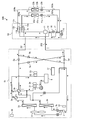
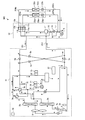
- FIG. 1 is a diagram illustrating a refrigerant circuit of an air-conditioning apparatus according to Embodiment 1 of the present invention.
- the circuit configuration of the air conditioner 500 will be described based on FIG.
- the air conditioner 500 performs a cooling operation and a heating operation using a refrigeration cycle such as a heat pump cycle for circulating a refrigerant.
- the air conditioning apparatus 500 illustrated in FIG. 1 is merely an example, and may include two or more outdoor units or a plurality of load-side units.
- the air conditioner 500 includes one outdoor unit 51 and two indoor units 53a and 53b. And the outdoor unit 51 is connected to the two indoor units 53a and 53b by the low pressure pipe 201 and the high pressure pipe 202, and the refrigerating cycle circuit is comprised.
- the outdoor unit 51 includes a compressor 1, four-way valves 3 a and 3 b, heat source side heat exchangers 2 a and 2 b, heat source side flow rate adjustment valves 7 a and 7 b, a heat source side bypass valve 8, and a distributor 9.
- the pipe in which the heat source side bypass valve 8 is arranged is a first bypass passage that bypasses between the four-way valve 3b and the heat source side heat exchanger 2b and between the heat source side heat exchanger 2b and the indoor side heat exchangers 22a and 22b. It is.
- the heat source side bypass valve 8 corresponds to the first bypass valve of the present invention.
- the heat source side flow rate adjustment valves 7a and 7b correspond to a plurality of flow rate adjustment valves provided in piping in which each of the plurality of heat source side heat exchangers of the present invention is arranged.
- the distributor 9 divides the piping into two so that the heat source side heat exchangers 2a and 2b are arranged in parallel.
- the outdoor unit 51 includes an accumulator 4, check valves 5 a, 5 b, 5 c, 5 d, and the outdoor blower 6. Furthermore, the outdoor unit 51 includes a compressor discharge pressure detection sensor 31, a heat exchanger outlet pressure detection sensor 32, a compressor discharge temperature detection sensor 34, a heat exchanger outlet temperature detection sensor 35, and an outside air temperature detection sensor 36. ing.
- the outdoor unit 51 is provided with a control unit 37 that controls the compressor 1, the four-way valves 3 a and 3 b, the heat source side flow rate adjustment valves 7 a and 7 b, and the heat source side bypass valve 8.
- the controller 37 includes a compressor discharge pressure detection sensor 31, a heat exchanger outlet pressure detection sensor 32, a compressor discharge temperature detection sensor 34, a heat exchanger outlet temperature detection sensor 35, and an outside air temperature detection sensor 36. Connected and these detection values are input.
- the control unit 37 has a microcomputer including a CPU, a ROM, a RAM, an I / O port, and the like.
- Four-way valves 3 a and 3 b are connected to the discharge side of the compressor 1.
- the four-way valves 3a and 3b switch the flow path of the refrigerant discharged from the compressor 1 to a flow path that flows to the heat source side heat exchangers 2a and 2b or a flow path that flows to the indoor units 53a and 53b.
- the four-way valves 3a and 3b are also connected to the accumulator 4 and send the refrigerant flowing from the heat source side heat exchangers 2a and 2b or the indoor units 53a and 53b to the accumulator 4.
- the four-way valves 3a and 3b correspond to the flow path switching device of the present invention.
- the flow path switching device is not limited to a four-way switching valve, and may be configured by combining, for example, a two-way valve.
- the air conditioner 500 includes an outdoor unit 51, a plurality of indoor units 53a and 53b, and a shunt controller 52.
- a shunt controller 52 is provided between the outdoor unit 51 and the indoor units 53a and 53b, and these devices are connected by various refrigerant pipes.
- the plurality of indoor units 53a and 53b are connected in parallel with each other. Note that, for example, in the indoor unit 53a and the indoor unit 53b, when there is no need to particularly distinguish or specify, the subscripts a and b may be omitted below.
- the outdoor unit 51 and the shunt controller 52 are connected by a low pressure pipe 201 and a high pressure pipe 202.
- a high-pressure refrigerant flows from the outdoor unit 51 side to the shunt controller 52 side.
- a refrigerant having a lower pressure flows through the low pressure pipe 201 than the refrigerant flowing through the high pressure pipe 202 from the shunt controller 52 side to the outdoor unit 51.
- the level of the pressure is not determined by the relationship with the pressure such as a reference numerical value.
- the level of the pressure is expressed based on the level including the relative middle in the refrigerant circuit by controlling the opening degree or the open / closed state of each throttle device such as the pressurization of the compressor 1 and the flow rate adjusting device.
- the shunt controller 52 and the indoor unit 53a are connected by a liquid pipe 203a and a gas pipe 204a.
- the diversion controller 52 and the indoor unit 53b are connected by a liquid pipe 203b and a gas pipe 204b.
- the four-way valves 3a and 3b perform valve switching corresponding to a mode that is a mode of air conditioning operation so that the refrigerant path is switched.
- the path is switched between the cooling only operation mode and the cooling main operation mode, and the heating only operation mode and the heating main operation mode.
- the operation when all of the indoor units 53a and 53b that are performing air conditioning are cooling is referred to as a cooling only operation.
- an operation with a large cooling load is referred to as a cooling main operation.
- the operation when all the indoor units 53a and 53b that are performing the air conditioning are heating is referred to as a full heating operation.
- an operation with a large heating load is called a heating-based operation.
- the heat source side heat exchangers 2a and 2b have heat transfer tubes that allow the refrigerant to pass therethrough and fins for increasing the heat transfer area between the refrigerant flowing through the heat transfer tubes and the outside air. Perform heat exchange.
- the heat source side heat exchangers 2a and 2b function as an evaporator during, for example, the all heating operation and the heating main operation, and evaporate and evaporate the refrigerant.
- the heat source side heat exchangers 2a and 2b function as a condenser, for example, during the cooling only operation and the cooling main operation, and condense and liquefy the refrigerant.
- the heat source side heat exchangers 2a and 2b are not completely gasified or liquefied, for example, in the cooling main operation, but are in a gas-liquid two-phase state in which liquid and gas are mixed in two phases. Adjustments such as condensation are performed.
- the check valves 5a, 5b, 5c, and 5d prevent the refrigerant from flowing backward to adjust the flow of the refrigerant, and make the refrigerant circulation path constant according to the mode.
- the check valve 5a is located on the pipe between the four-way valve 3b and the low-pressure pipe 201, and allows the refrigerant flow from the low-pressure pipe 201 to the four-way valve 3b.
- the check valve 5b is located on the pipe between the heat source side heat exchangers 2a, 2b and the low pressure pipe 201, and allows the refrigerant flow from the low pressure pipe 201 toward the heat source side heat exchangers 2a, 2b.
- the check valve 5 c is located on the pipe between the four-way valve 3 b and the high-pressure pipe 202, and allows the refrigerant flow from the four-way valve 3 b to the high-pressure pipe 202.
- the check valve 5d is located on the pipe between the heat source side heat exchangers 2a and 2b and the high pressure pipe 202, and allows the refrigerant flow from the heat source side heat exchangers 2a and 2b to the high pressure pipe 202.
- a compressor discharge pressure detection sensor 31 that detects the pressure of the refrigerant on the discharge side of the compressor 1 is attached on the piping on the discharge side of the compressor 1.
- a heat exchanger outlet pressure detection sensor 32 that detects the pressure of the refrigerant on the outlet side of the heat source side heat exchangers 2a and 2b during heating operation is attached.
- a compressor discharge temperature detection sensor 34 that detects the temperature of the refrigerant on the high pressure side is attached to the piping on the discharge side of the compressor 1.
- a heat exchanger outlet temperature detection sensor 35 for detecting the outlet temperature of the heat source side heat exchangers 2a and 2b is attached to the pipe on the suction side of the compressor 1.
- an outside air temperature detection sensor 36 that detects the ambient temperature of the outdoor unit 51 is attached.
- the diversion controller 52 has the gas-liquid separator 11.
- the gas-liquid separator 11 separates the refrigerant flowing from the high-pressure pipe 202 into a gas refrigerant and a liquid refrigerant.
- a gas phase portion (not shown) from which the gas refrigerant flows out is connected to the electromagnetic valves 12a and 12b.
- a liquid phase portion (not shown) from which the liquid refrigerant flows is connected to the inter-refrigerant heat exchanger 16.
- the electromagnetic valves 12a, 12b, 13a, 13b are opened and closed based on the operation mode.
- One ends of the electromagnetic valves 12 a and 12 b are connected to the gas-liquid separator 11.
- the other ends of the electromagnetic valves 12a and 12b are connected to gas pipes 204a and 204b, respectively.
- one ends of the electromagnetic valves 13a and 13b are connected to the gas pipes 204a and 204b, respectively.
- the other ends of the electromagnetic valves 13 a and 13 b are connected to the low pressure pipe 201.
- the solenoid valves 12a, 12b, 13a, and 13b are combined to allow the refrigerant to flow from the indoor unit 53 side to the low-pressure pipe 201 side based on the operation mode, or from the gas-liquid separator 11 side to the indoor unit.
- the valve is switched so that the refrigerant flows to the 53 side.
- the flow of the refrigerant is switched by the electromagnetic valves 12 and 13.
- a three-way valve or the like may be used instead of the electromagnetic valve.
- the expansion device 14 is provided between the inter-refrigerant heat exchanger 16 and the inter-refrigerant heat exchanger 17.
- the expansion device 14 controls the opening degree based on the operation mode, and adjusts the flow rate of refrigerant flowing from the gas-liquid separator 11 and the pressure of the refrigerant.
- the expansion device 15 controls the opening and adjusts the refrigerant flow rate and the refrigerant pressure.
- the refrigerant that has passed through the expansion device 15 supercools the refrigerant in the inter-refrigerant heat exchanger 17 and the inter-refrigerant heat exchanger 16, for example, and flows to the low-pressure pipe 201.
- the inter-refrigerant heat exchanger 17 performs heat exchange between the refrigerant in the downstream portion of the expansion device 15 that has passed through the expansion device 15 and the refrigerant flowing from the expansion device 14.
- the inter-refrigerant heat exchanger 16 exchanges heat between the refrigerant that has passed through the inter-refrigerant heat exchanger 17 and the liquid refrigerant that flows from the gas-liquid separator 11 toward the expansion device 14.
- the indoor unit 53a includes an indoor side heat exchanger 22a and an indoor side expansion device 23a connected in series in proximity to the indoor side heat exchanger 22a.
- the indoor unit 53b has an indoor side heat exchanger 22b and an indoor side expansion device 23b connected in series in proximity to the indoor side heat exchanger 22b.
- the indoor side heat exchanger 22 serves as an evaporator during cooling operation, and serves as a condenser during heating operation, and exchanges heat between air and refrigerant in the air-conditioning target space. I do. Here, you may provide the air blower which performs the heat exchange with a refrigerant
- the indoor side expansion device 23 functions as a pressure reducing valve or an expansion valve, and adjusts the pressure of the refrigerant passing through the indoor side heat exchanger 22.
- the indoor expansion device 23 according to Embodiment 1 is configured with, for example, an electronic expansion valve that can change the opening degree.
- the opening degree of the indoor expansion device 23 is determined based on the degree of superheat on the refrigerant outlet side of the indoor heat exchanger 22 on the gas pipe 204 side during the cooling operation. Further, the opening degree of the indoor expansion device 23 is determined based on the degree of supercooling on the refrigerant outlet side of the indoor heat exchanger 22 on the liquid pipe 203 side during heating operation.
- the air conditioner 500 configured as described above can be operated in any one of the four modes of the cooling only operation, the heating only operation, the cooling main operation, and the heating main operation.
- FIG. 2 is a diagram showing a refrigerant flow in the heating only operation of the air-conditioning apparatus 500 according to Embodiment 1 of the present invention.
- the operation of each device and the flow of refrigerant in the heating only operation will be described.
- the flow of the refrigerant during the all-heating operation is indicated by solid line arrows in FIG.
- the outdoor unit 51 the refrigerant sucked by the compressor 1 is compressed and high-pressure gas refrigerant is discharged.
- the refrigerant discharged from the compressor 1 flows through the four-way valve 3b and the check valve 5c, and does not flow to the check valve 5a and check valve 5d side due to the refrigerant pressure.
- the refrigerant that has flowed through the check valve 5 c flows into the branch flow controller 52 through the high-pressure pipe 202.
- the solenoid valves 12a and 12b are opened, and the solenoid valves 13a and 13b are closed.
- the gas refrigerant that has flowed into the diversion controller 52 passes through the gas-liquid separator 11, the electromagnetic valves 12a and 12b, and the gas pipes 204a and 204b, and flows into the indoor units 53a and 53b.
- the flow rate of the refrigerant flowing through the indoor heat exchangers 22a and 22b is adjusted by adjusting the opening of the indoor expansion devices 23a and 23b.
- the high-pressure gas refrigerant is condensed by heat exchange while passing through the indoor heat exchangers 22a and 22b, and passes through the indoor expansion devices 23a and 23b.
- the room air is heated by heat exchange to heat the room that is the air-conditioning target space.
- the refrigerant that has passed through the indoor expansion devices 23a and 23b becomes, for example, an intermediate-pressure liquid refrigerant or a gas-liquid two-phase refrigerant, passes through the liquid pipes 203a and 203b, flows to the inter-refrigerant heat exchanger 17, and passes through the expansion device 15. pass.
- the expansion device 15 the refrigerant is decompressed.
- the refrigerant that has been reduced in pressure after passing through the expansion device 15 flows into the low-pressure pipe 201 and flows into the outdoor unit 51.
- the refrigerant flowing into the outdoor unit 51 passes through the check valve 5b of the outdoor unit 51, is divided into two pipes by the distributor 9, passes through the heat source side flow rate adjusting valves 7a, 7b, and then the heat source side heat exchanger 2a. 2b.
- the refrigerant flowing into the heat source side heat exchangers 2a and 2b evaporates into a gas refrigerant by heat exchange with air while passing through the heat source side heat exchangers 2a and 2b.
- the gas refrigerant passes through the four-way valves 3a and 3b and the accumulator 4, and returns to the compressor 1 to be discharged again. This is the refrigerant circulation path during the all-heating operation.
- on-defrost there are two cases: defrosting the heat source side heat exchanger 2a and defrosting the heat source side heat exchanger 2b.
- the case where the heat source side heat exchanger 2b is defrosted is referred to as a first on defrost
- the case where the heat source side heat exchanger 2a is defrosted is referred to as a second on defrost.
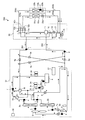
- FIG. 3 is a diagram showing a refrigerant flow in the first on-defrost operation of the air-conditioning apparatus 500 according to Embodiment 1 of the present invention.
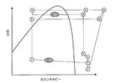
- FIG. 4 is a Ph diagram illustrating the change of the refrigerant in the first on-defrost operation of the air-conditioning apparatus 500 according to Embodiment 1 of the present invention.
- the refrigerant sucked by the compressor 1 is compressed and high-pressure gas refrigerant is discharged.
- the refrigerant discharged from the compressor 1 passes through the four-way valve 3b and is divided into a refrigerant flowing through the heat source side heat exchanger 2b and a refrigerant flowing through the heat source side bypass valve 8.
- the refrigerant flowing to the heat source side heat exchanger 2b can flow a high-temperature and high-pressure gas refrigerant, and the refrigerant kept at a high condensation temperature can be flowed to the heat source side heat exchanger 2b for defrosting. growing.
- the opening degree of the heat source side bypass valve 8 is set to a predetermined opening degree C1.
- the refrigerant that has flowed to the heat source side bypass valve 8 is divided into the refrigerant that flows to the heat source side heat exchanger 2a and the refrigerant that flows to the check valve 5d.
- the refrigerant flowing through the heat source side heat exchanger 2b passes through the heat source side flow rate adjusting valve 7b, merges with the refrigerant flowing through the heat source side bypass valve 8, and evaporates as shown in FIGS.
- the valve opening degree of the heat source side flow rate adjustment valve 7a is set to a predetermined opening degree A1.
- the valve opening degree of the heat source side flow rate adjustment valve 7b is set to a predetermined opening degree B1.
- the refrigerant that has flowed into the check valve 5d flows into the flow dividing controller 52 through the high-pressure pipe 202.
- the solenoid valves 12a and 12b are opened, and the solenoid valves 13a and 13b are closed.
- the gas refrigerant that has flowed into the diversion controller 52 passes through the gas-liquid separator 11, the electromagnetic valves 12a and 12b, and the gas pipes 204a and 204b, and flows into the indoor units 53a and 53b.
- the flow rate of the refrigerant flowing through the indoor heat exchangers 22a and 22b is adjusted by adjusting the opening of the indoor expansion devices 23a and 23b.
- the high-pressure gas refrigerant is condensed by heat exchange while passing through the indoor heat exchangers 22a and 22b, and passes through the indoor expansion devices 23a and 23b.
- the refrigerant passing through the indoor heat exchangers 22a and 22b heats the indoor air by heat exchange and heats the indoor air conditioning target space.
- the refrigerant that has passed through the indoor expansion devices 23a and 23b becomes, for example, an intermediate-pressure liquid refrigerant or a gas-liquid two-phase refrigerant, passes through the liquid pipes 203a and 203b, flows to the inter-refrigerant heat exchanger 17, and passes through the expansion device 15. pass.
- the expansion device 15 the refrigerant is decompressed.
- the refrigerant that has been reduced in pressure after passing through the expansion device 15 flows into the low-pressure pipe 201 and flows into the outdoor unit 51.
- the refrigerant that has flowed into the outdoor unit 51 passes through the check valve 5a of the outdoor unit 51 and passes through the four-way valve 3b.
- the refrigerant flowing into the heat source side heat exchanger 2a through the heat source side flow rate adjusting valve 7a merges with the refrigerant that passes through the heat source side heat exchanger 2b and then passes through the heat source side heat exchanger 2b, and evaporates. It becomes a refrigerant and passes through the heat source side heat exchanger 2a and the four-way valve 3a.
- the refrigerant that has passed through the check valve 5a and passed through the four-way valve 3b and the refrigerant that has passed through the heat source side heat exchanger 2a join together, as shown in (i) to (f) of FIG. It evaporates, passes through the accumulator 4, returns to the compressor 1 and is discharged again. This is the circulation path of the first on-defrost refrigerant.
- the compressor 1, the four-way valve 3b, the heat source side heat exchanger 2b for performing the defrosting, and the heat source side A defrost circuit is configured by connecting the flow rate adjusting valve 7b with a pipe.
- the compressor 1, the four-way valve 3b, the indoor heat exchanger 22 and the indoor expansion device 23 are connected by piping to form a heating circuit.
- FIG. 5 is a diagram showing a refrigerant flow in the second on-defrost operation of the air-conditioning apparatus 500 according to Embodiment 1 of the present invention.
- FIG. 6 is a Ph diagram showing the change of the refrigerant in the second on-defrost operation of the air-conditioning apparatus 500 according to Embodiment 1 of the present invention.
- the refrigerant sucked by the compressor 1 is compressed and high-pressure gas refrigerant is discharged.
- the refrigerant discharged from the compressor 1 is divided into the four-way valve 3a and the four-way valve 3b.
- the refrigerant that has flowed to the four-way valve 3b flows through the check valve 5c and does not flow toward the check valve 5a and the check valve 5d due to the refrigerant pressure.
- the refrigerant that has flowed through the check valve 5 c flows into the branch flow controller 52 through the high-pressure pipe 202.
- the refrigerant that has flowed to the four-way valve 3a passes through the heat source side heat exchanger 2a, passes through the heat source side flow rate adjustment valve 7a, passes through the distributor 9 and passes through the heat source side flow rate adjustment valve 7b.
- the refrigerant flowing through the heat source side heat exchanger 2a can flow a high-temperature and high-pressure gas refrigerant, and the refrigerant kept at a high condensation temperature can be flowed to the heat source side heat exchanger 2a for defrosting. growing.
- the opening degree of the heat source side flow rate adjustment valve 7a is a predetermined opening degree A2
- the opening degree of the heat source side flow rate adjustment valve 7b is a predetermined opening degree B2.
- the opening degree of the heat source side bypass valve 8 is set to a predetermined opening degree C2.
- the solenoid valves 12a and 12b are opened, and the solenoid valves 13a and 13b are closed.
- the gas refrigerant that has flowed into the diversion controller 52 passes through the gas-liquid separator 11, the electromagnetic valves 12a and 12b, and the gas pipes 204a and 204b, and flows into the indoor units 53a and 53b.
- the flow rate of the refrigerant flowing through the indoor heat exchangers 22a and 22b is adjusted by adjusting the opening of the indoor expansion devices 23a and 23b.
- the high-pressure gas refrigerant is condensed by heat exchange while passing through the indoor heat exchangers 22a and 22b, and passes through the indoor expansion devices 23a and 23b.
- the indoor air is heated to heat the room, which is the air-conditioning target space, by heat exchange while passing through the indoor heat exchangers 22a and 22b.
- the refrigerant that has passed through the indoor expansion devices 23a and 23b becomes, for example, an intermediate-pressure liquid refrigerant or a gas-liquid two-phase refrigerant, passes through the liquid pipes 203a and 203b, flows to the inter-refrigerant heat exchanger 17, and passes through the expansion device 15. pass.
- the expansion device 15 the refrigerant is decompressed.
- the refrigerant that has been reduced in pressure after passing through the expansion device 15 flows into the low-pressure pipe 201 and flows into the outdoor unit 51.
- the refrigerant that has flowed into the outdoor unit 51 passes through the check valve 5b of the outdoor unit 51, merges with the refrigerant that has passed through the heat source side heat exchanger 2a in the distributor 9, and passes through the heat source side flow rate adjustment valve 7b. It flows into the heat source side heat exchanger 2b. While passing through the heat source side heat exchanger 2b, the refrigerant evaporates by heat exchange with air and becomes a gas refrigerant. And it returns to the compressor 1 again through the four-way valve 3b and the accumulator 4, and is discharged. This is the circulation path of the second on-defrost refrigerant.
- the compressor 1, the four-way valve 3a, the heat source side heat exchanger 2a for performing the defrosting, and the heat source side A defrost circuit is configured by connecting the flow rate adjusting valve 7a with a pipe.
- the compressor 1, the four-way valve 3b, the indoor heat exchanger 22 and the indoor expansion device 23 are connected by piping to form a heating circuit.
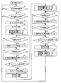
- FIG. 7 is a flowchart showing operation mode control of the air-conditioning apparatus 500 according to Embodiment 1 of the present invention.
- the control flow shown in FIG. 7 according to Embodiment 1 will be described.
- the control unit 37 determines whether or not the heating continuous operation time Time1 has passed the predetermined time Z1 (S1).
- the control unit 37 next determines whether the heat exchanger inlet temperature T33 is lower than the predetermined temperature T1 by the heat exchanger inlet temperature detection sensor 33. Is determined (S2). That is, S2 detects whether the heat source side heat exchanger 2 needs to be defrosted based on the inlet temperature of the heat source side heat exchanger 2 during the heating only operation.
- the controller 37 starts the first on-defrost when it is determined in S2 that the heat exchange inlet temperature T33 is lower than the predetermined temperature T1 (S3).
- the control unit 37 switches the four-way valve 3b (S4), sets the opening degree of the heat source side flow rate adjustment valve 7a to A1, sets the opening degree of the heat source side flow rate adjustment valve 7b to B1, and sets the opening degree of the heat source side bypass valve 8 to C1. (S5).
- the controller 37 determines whether or not the compressor discharge pressure Pd is smaller than a predetermined pressure P1 by the compressor discharge pressure detection sensor 31 (S6).
- the control unit 37 determines that the heating capacity is insufficient when the compressor discharge pressure Pd is smaller than the predetermined pressure P1, opens the predetermined amount ⁇ C of the heat source side bypass valve 8, and increases the refrigerant flowing to the indoor unit 53 side. (S7). That is, when a lack of indoor heating capacity is detected based on the compressor discharge pressure Pd of the compressor 1, the heat source side bypass valve 8 increases the amount of refrigerant circulating in the heating circuit by adjusting the opening.
- the control unit 37 determines whether or not the compressor suction pressure Ps is smaller than the predetermined pressure P2 by the heat exchanger outlet pressure detection sensor 32 (S8). When the compressor suction pressure Ps is smaller than the predetermined pressure P2, the control unit 37 determines that the evaporation capacity on the outdoor unit 51 side is insufficient, and opens the opening of the heat source side flow rate adjustment valve 7a by a predetermined amount ⁇ A (S9). ).
- the control unit 37 determines whether or not the on-defrost operation time Time2 has passed a predetermined time Z2 (S10).
- the control unit 37 determines that the defrosting of the heat source side heat exchanger 2b is completed, and shifts to the second on-defrost (S11).
- the control unit 37 switches the four-way valves 3a and 3b (S12), the opening degree of the heat source side flow rate adjustment valve 7a is set to A2, the opening degree of the heat source side flow rate adjustment valve 7b is set to B2, and the opening degree of the heat source side bypass valve 8 is set. Is C2 (S13).
- the control unit 37 determines whether or not the compressor discharge pressure Pd is smaller than the predetermined pressure P1 by the compressor discharge pressure detection sensor 31 (S14).
- the control unit 37 determines that the heating capacity is insufficient, closes the opening of the heat source side flow rate adjustment valve 7a by a predetermined amount ⁇ A, and flows into the indoor unit 53 side. Is increased (S15). That is, when a lack of indoor heating capacity is detected based on the compressor discharge pressure Pd of the compressor 1, the heat source side flow rate adjustment valve 7a increases the amount of refrigerant circulating in the heating circuit by adjusting the opening.
- the control unit 37 determines whether or not the compressor suction pressure Ps is smaller than a predetermined pressure P2 by the heat exchanger outlet pressure detection sensor 32 (S16). When the compressor suction pressure Ps is smaller than the predetermined pressure P2, the control unit 37 determines that the evaporation capacity on the outdoor unit 51 side is insufficient, and opens the opening of the heat source side flow rate adjustment valve 7b by a predetermined amount ⁇ B (S17). ).
- the control unit 37 determines whether or not the on-defrost operation time Time3 has passed a predetermined time Z3 (S18).
- the control unit 37 determines that the defrosting of the heat source side heat exchanger 2a is completed, ends the on-defrost operation, and shifts to the heating only operation. Therefore, the four-way valves 3a and 3b are switched (S19).
- the control unit 37 sets the opening degree of the heat source side flow rate adjustment valve 7a to A3, sets the opening degree of the heat source side flow rate adjustment valve 7b to B3, and sets the opening degree of the heat source side flow rate adjustment valve 8 to C3 (S20). Control of on-defrost operation is completed in one cycle.
- FIG. 8 is a diagram illustrating a case where hot gas is allowed to flow in the first on-defrost operation of the air-conditioning apparatus 500 according to Embodiment 1 of the present invention.
- a countermeasure when the refrigerant is not evaporated during the first on-defrost operation and returns to the compressor 1 will be described.
- the flow of the refrigerant is indicated by solid line arrows shown in FIG.
- the refrigerant that has passed through the check valve 5a after condensing in the indoor heat exchanger 22 passes through the heat source side heat exchanger 2 as shown in FIGS. Without flowing to the accumulator 4.
- the liquid refrigerant gradually accumulates in the accumulator 4 and may overflow.
- the outdoor unit 51 includes an accumulator 4 disposed in a pipe on the upstream side of the compressor 1 and a second bypass that distributes the refrigerant on the discharge side of the compressor 1 to the pipe on the upstream side of the accumulator 4.
- a pipe having a hot gas bypass valve 10 as a passage is disposed.
- the hot gas bypass valve 10 corresponds to the second bypass valve of the present invention.
- the control unit 37 includes a refrigerant evaporation temperature converted by the heat exchanger outlet pressure detected by the heat exchanger outlet pressure detection sensor 32, a heat exchanger outlet temperature detected by the heat exchanger outlet temperature detection sensor 35, and Thus, the concern about the overflow of the liquid refrigerant is determined.
- the control unit 37 When the control unit 37 detects that the liquid refrigerant overflows, the control unit 37 opens the hot gas bypass valve 10 and causes the compressor discharge side refrigerant to flow through the pipe provided with the hot gas bypass valve 10.
- the refrigerant that has passed through the pipe provided with the hot gas bypass valve 10 merges with the refrigerant that has passed through the check valve 5a, evaporates the condensed refrigerant by using the amount of refrigerant heat compressed by the compressor 1, and the liquid refrigerant Overflow is prevented.
- adopted for an air conditioning apparatus is not specifically limited,
- coolants such as R410A, R32, R407C, R404A, HFO1234yf, are used from natural refrigerant
- the air conditioner 500 includes the compressor 1, the four-way valves 3a and 3b, the plurality of heat source side heat exchangers 2a and 2b, the heat source side flow rate adjusting valves 7a and 7b, and the heat source side bypass valve 8. It has the outdoor unit 51 which has.
- An indoor unit having indoor heat exchangers 22a and 22b and indoor expansion devices 23a and 23b is provided. During the execution of the first on-defrost or the second on-defrost in which the defrosting of one of the heat source side heat exchangers 2a, 2b and the indoor heating are operated in parallel among the plurality of heat source side heat exchangers 2a, 2b.
- Machine 1 four-way valves 3a, 3b, heat source side heat exchangers 2a, 2b for performing defrosting of any of heat source side heat exchangers 2a, 2b, heat source side flow rate adjusting valves 7a, 7b and heat source side bypass valves 8 is connected to form a defrost circuit.
- the compressor 1, the four-way valves 3a and 3b, the indoor heat exchangers 22a and 22b, and the indoor expansion devices 23a and 23b are connected to form a heating circuit.
- the heat source side flow rate adjustment valves 7a and 7b and the heat source side bypass valve 8 increase or decrease the amount of refrigerant circulating in either the defrost circuit or the heating circuit by adjusting the opening. Is configured to do.
- the gas refrigerant discharged from the compressor 1 is divided into the refrigerant flowing in the indoor heat exchangers 22a and 22b and the refrigerant flowing in the heat source side heat exchangers 2a and 2b to be defrosted,
- the first on-defrost or the second on-defrost is performed to defrost the heat source side heat exchangers 2a and 2b while performing the heating operation.
- the heat source side heat exchangers 2a and 2b and the indoor side heat to be defrosted by adjusting the opening degree of the heat source side flow rate adjusting valves 7a and 7b and the heat source side bypass valve 8 during execution of the first on defrost or the second on defrost.
- the refrigerant circulation amount that is diverted to the exchangers 22a and 22b can be increased or decreased. Therefore, when the amount of frost formation is small, a large amount of refrigerant flows through the indoor heat exchangers 22a and 22b, so that the heating capacity can be improved. When the amount of frost formation is large, a large amount of refrigerant flows through the heat source side heat exchangers 2a and 2b to be defrosted so that defrosting can be performed reliably.
- the outdoor unit 51 has a first bypass passage that bypasses between the four-way valve 3b and the heat source side heat exchanger 2b and between the heat source side heat exchanger 2b and the indoor side heat exchangers 22a and 22b.
- the heat source side flow rate adjusting valves 7a and 7b and the heat source side bypass valve 8 are provided in a pipe in which each of the heat source side bypass valve 8 provided in the first bypass passage and the plurality of heat source side heat exchangers 2a and 2b is arranged. Heat source side flow rate regulating valves 7a, 7b.
- the heat source side heat exchangers 2a and 2b to be defrosted by adjusting the opening degrees of the heat source side flow rate adjusting valves 7a and 7b and the heat source side bypass valve 8 during execution of the first on defrost or the second on defrost. And the amount of refrigerant circulating in the indoor heat exchangers 22a and 22b can be increased or decreased.
- the heat source side bypass valve 8 or the heat source side flow rate adjustment valve 7a adjusts the degree of opening so that the amount of refrigerant circulating in the heating circuit Is configured to increase. According to this configuration, the lack of room heating capacity is solved during execution of the first on-defrost or the second on-defrost.
- the heat source side heat exchangers 2a and 2b are configured to detect whether or not defrosting is necessary based on the inlet temperatures of the heat source side heat exchangers 2a and 2b. According to this configuration, it is possible to appropriately determine the execution opportunity of the first on-defrost or the second on-defrost.
- the outdoor unit 51 includes an accumulator 4 disposed in a pipe on the upstream side of the compressor 1, a pipe for circulating the refrigerant on the discharge side of the compressor 1 through a pipe on the upstream side of the accumulator 4, and a hot provided in the pipe And a gas bypass valve 10. Hot gas bypass when a liquid refrigerant overflow concern of the accumulator 4 is detected based on the heat exchanger outlet pressure of the heat source side heat exchangers 2a and 2b and the heat exchanger outlet temperature of the heat source side heat exchangers 2a and 2b.
- the valve 10 is configured to prevent overflow of the liquid refrigerant in the accumulator 4 by opening the valve to evaporate the refrigerant using the amount of heat of the refrigerant.
- the hot gas bypass valve 10 is opened to cause the refrigerant to evaporate using the amount of refrigerant heat, thereby overflowing the liquid refrigerant in the accumulator 4. Can be prevented.
Landscapes
- Engineering & Computer Science (AREA)
- Mechanical Engineering (AREA)
- General Engineering & Computer Science (AREA)
- Physics & Mathematics (AREA)
- Thermal Sciences (AREA)
- Chemical & Material Sciences (AREA)
- Combustion & Propulsion (AREA)
- Analytical Chemistry (AREA)
- Power Engineering (AREA)
- Air Conditioning Control Device (AREA)
Abstract
オンデフロスト実行中に熱源側流量調整弁の開度調整によって除霜される熱源側熱交換器と室内側熱交換器に分流する冷媒循環量を増減し、着霜量が少ない場合は暖房能力を向上し、また着霜量が多い場合は除霜を確実に行う。空気調和装置は、オンデフロスト実行時に、デフロスト回路を構成し、かつ、暖房回路を構成し、オンデフロスト実行状態では、熱源側流量調整弁は、開度調整により、デフロスト回路と暖房回路とのどちらかを循環する冷媒量を増減するように構成された。
Description
本発明は、暖房運転中に並行して熱交換器の除霜を可能とした機構を冷媒回路内に備えた空気調和装置に関する。
従来、熱源側熱交換器の除霜形態としてリバースデフロストを用いた空気調和装置が知られている。
このような空気調和装置の除霜を行う際には、除霜時に暖房運転が停止されるため、暖房能力が損なわれる(たとえば、特許文献1参照)。
このような空気調和装置の除霜を行う際には、除霜時に暖房運転が停止されるため、暖房能力が損なわれる(たとえば、特許文献1参照)。
また、他にも既存の形態で暖房運転を継続しながら除霜をする空気調和装置が知られている。この形態をオンデフロストと称する。オンデフロストでは、除霜のために流す流量が固定弁を用いて調整されるため、室内側熱交換器に流す冷媒流量が不足し、暖房能力不足になる可能性がある(たとえば、特許文献2参照)。
加えて、除霜される熱源側熱交換器に流す冷媒が固定弁を通り減圧されるため、冷媒の凝縮温度が下がることで除霜能力が低下し、除霜不良になる可能性がある。
加えて、除霜される熱源側熱交換器に流す冷媒が固定弁を通り減圧されるため、冷媒の凝縮温度が下がることで除霜能力が低下し、除霜不良になる可能性がある。
従来の除霜方法では、リバースデフロストの場合は、暖房停止による暖房能力の低下が課題となる。
また、従来のオンデフロストの場合は、除霜のために流す流量が固定弁で調整される。このため、室内側熱交換器に流す冷媒流量が不足し、暖房能力が不足する課題がある。加えて、除霜される熱源側熱交換器に流す冷媒が固定弁で減圧され、冷媒の凝縮温度が下がることで、除霜能力が低下し、除霜不良になる課題がある。
また、従来のオンデフロストの場合は、除霜のために流す流量が固定弁で調整される。このため、室内側熱交換器に流す冷媒流量が不足し、暖房能力が不足する課題がある。加えて、除霜される熱源側熱交換器に流す冷媒が固定弁で減圧され、冷媒の凝縮温度が下がることで、除霜能力が低下し、除霜不良になる課題がある。
本発明は、上記課題を解決するためのものであり、オンデフロスト実行中に熱源側流量調整弁の開度調整によって除霜される熱源側熱交換器と室内側熱交換器に分流する冷媒循環量を増減し、着霜量が少ない場合は暖房能力を向上し、また着霜量が多い場合は除霜を確実に行う空気調和装置を提供することを目的とする。
本発明に係る空気調和装置は、圧縮機、流路切替装置、複数の熱源側熱交換器および熱源側流量調整弁を有する室外機と、室内側熱交換器および室内側絞り装置を有する室内機と、を備え、前記複数の熱源側熱交換器のうちいずれかの熱源側熱交換器の除霜と室内の暖房とを並行して運転するオンデフロスト実行時に、前記圧縮機、前記流路切替装置、前記複数の熱源側熱交換器のうちいずれかの除霜を行う熱源側熱交換器および前記熱源側流量調整弁を接続してデフロスト回路を構成し、かつ、前記圧縮機、前記流路切替装置、前記室内側熱交換器および前記室内側絞り装置を接続して暖房回路を構成し、オンデフロスト実行状態では、前記熱源側流量調整弁は、開度調整により、前記デフロスト回路と前記暖房回路とのどちらかを循環する冷媒量を増減するように構成されたものである。
本発明に係る空気調和装置によれば、圧縮機から吐出されたガス冷媒が室内側熱交換器に流れる冷媒と除霜される熱源側熱交換器に流れる冷媒に分流されることで、暖房運転を行いながら熱源側熱交換器の除霜を行うオンデフロストが実行される。
また、オンデフロスト実行中に熱源側流量調整弁の開度調整によって、除霜される熱源側熱交換器と室内側熱交換器とに分流する冷媒循環量が増減できる。したがって、着霜量が少ない場合は室内側熱交換器に冷媒が多く流され暖房能力が向上できる。また、着霜量が多い場合は除霜される熱源側熱交換器に多く冷媒が流され除霜が確実に行える。
また、オンデフロスト実行中に熱源側流量調整弁の開度調整によって、除霜される熱源側熱交換器と室内側熱交換器とに分流する冷媒循環量が増減できる。したがって、着霜量が少ない場合は室内側熱交換器に冷媒が多く流され暖房能力が向上できる。また、着霜量が多い場合は除霜される熱源側熱交換器に多く冷媒が流され除霜が確実に行える。
以下、図面に基づいて本発明の実施の形態について説明する。
なお、各図において、同一の符号を付したものは、同一のまたはこれに相当するものであり、これは明細書の全文において共通している。
さらに、明細書全文に示されている構成要素の形態は、あくまで例示であってこれらの記載に限定されるものではない。
なお、各図において、同一の符号を付したものは、同一のまたはこれに相当するものであり、これは明細書の全文において共通している。
さらに、明細書全文に示されている構成要素の形態は、あくまで例示であってこれらの記載に限定されるものではない。
実施の形態1.
図1は、本発明の実施の形態1に係る空気調和装置の冷媒回路を示す図である。図1に基づいて、空気調和装置500の回路構成について説明する。
空気調和装置500は、冷媒を循環させるヒートポンプサイクルといった冷凍サイクルを利用し、冷房運転および暖房運転を行う。図1に示す空気調和装置500は、あくまでも一例であり、室外機を2つ以上備えてもよいし、複数の負荷側ユニットを備えていてもよい。
図1は、本発明の実施の形態1に係る空気調和装置の冷媒回路を示す図である。図1に基づいて、空気調和装置500の回路構成について説明する。
空気調和装置500は、冷媒を循環させるヒートポンプサイクルといった冷凍サイクルを利用し、冷房運転および暖房運転を行う。図1に示す空気調和装置500は、あくまでも一例であり、室外機を2つ以上備えてもよいし、複数の負荷側ユニットを備えていてもよい。
空気調和装置500は、1つの室外機51および2つの室内機53a、53bを備えている。そして、室外機51は、低圧管201および高圧管202によって2つの室内機53a、53bに接続され、冷凍サイクル回路が構成されている。
室外機51は、圧縮機1、四方弁3a、3b、熱源側熱交換器2a、2b、熱源側流量調整弁7a、7b、熱源側バイパス弁8、および分配器9を有している。熱源側バイパス弁8が配置された配管は、四方弁3bおよび熱源側熱交換器2bの間と熱源側熱交換器2bおよび室内側熱交換器22a、22bの間とをバイパスする第1バイパス通路である。熱源側バイパス弁8は、本発明の第1バイパス弁に相当する。また、熱源側流量調整弁7a、7bは、本発明の複数の熱源側熱交換器のそれぞれが配置された配管に設けられた複数の流量調整弁に相当する。分配器9は、熱源側熱交換器2a、2bを並列に配置するよう配管を2つに分ける。
また、室外機51は、アキュムレータ4、逆止弁5a、5b、5c、5d、および室外送風機6を有している。さらに、室外機51は、圧縮機吐出圧力検知センサ31、熱交換器出口圧力検知センサ32、圧縮機吐出温度検知センサ34、熱交換器出口温度検知センサ35、および外気温度検知センサ36を有している。
室外機51には、圧縮機1、四方弁3a、3b、熱源側流量調整弁7a、7b、および熱源側バイパス弁8を制御する制御部37が設けられている。制御部37には、圧縮機吐出圧力検知センサ31、熱交換器出口圧力検知センサ32、圧縮機吐出温度検知センサ34、熱交換器出口温度検知センサ35、および外気温度検知センサ36が電気的に接続され、これらの検出値が入力される。制御部37は、CPU、ROM、RAM、I/Oポートなどを備えたマイコンを有している。
圧縮機1の吐出側には、四方弁3a、3bが接続されている。四方弁3a、3bは、圧縮機1から吐出された冷媒の流路を熱源側熱交換器2a、2bへ流れる流路、または室内機53a、53bへ流れる流路に切り替えるものである。また、四方弁3a、3bは、アキュムレータ4とも接続され、熱源側熱交換器2a、2b、または室内機53a、53bから流入した冷媒をアキュムレータ4に送る。
ここで、四方弁3a、3bが本発明の流路切替装置に相当する。なお、流路切替装置は、四方切替え弁に限らず、たとえば二方弁などを組み合わせて構成してもよい。
ここで、四方弁3a、3bが本発明の流路切替装置に相当する。なお、流路切替装置は、四方切替え弁に限らず、たとえば二方弁などを組み合わせて構成してもよい。
実施の形態1に係る空気調和装置500は、室外機51と、複数の室内機53a、53bと、分流コントローラ52と、から構成される。実施の形態1では、冷媒の流れを制御するために室外機51と室内機53a、53bとの間に分流コントローラ52を設け、これらの機器の間を各種冷媒配管により配管接続する。また、複数台の室内機53a、53bについては、互いに並列となるように接続する。
なお、たとえば、室内機53aおよび室内機53bなどにおいて、特に区別したり、特定したりする必要がない場合には、以下、a、bの添え字を省略して記載する場合もある。
なお、たとえば、室内機53aおよび室内機53bなどにおいて、特に区別したり、特定したりする必要がない場合には、以下、a、bの添え字を省略して記載する場合もある。
配管接続については、室外機51と分流コントローラ52との間は、低圧管201と高圧管202とにより接続する。高圧管202には、室外機51側から分流コントローラ52側に高圧の冷媒が流れる。また、低圧管201には、分流コントローラ52側から室外機51に高圧管202を流れる冷媒に比べて低圧の冷媒が流れる。
ここで、圧力の高低については、基準となる数値などの圧力との関係により定められているものではない。圧力の高低は、圧縮機1の加圧、流量調整装置といった各絞り装置の開度または開閉状態の制御などにより、冷媒回路内において相対的な中間を含む高低に基づいて表すものである。
ここで、圧力の高低については、基準となる数値などの圧力との関係により定められているものではない。圧力の高低は、圧縮機1の加圧、流量調整装置といった各絞り装置の開度または開閉状態の制御などにより、冷媒回路内において相対的な中間を含む高低に基づいて表すものである。
一方、分流コントローラ52と室内機53aとは、液管203aとガス管204aとにより接続される。同様に、分流コントローラ52と室内機53bとは、液管203bとガス管204bとにより接続される。低圧管201、高圧管202、液管203、およびガス管204による配管接続により、室外機51、分流コントローラ52並びに室内機53の間を冷媒が循環し、冷媒回路が構成される。
四方弁3a、3bは、冷暖房運転の形態であるモードに対応した弁の切り替えを行い、冷媒の経路が切り換わるようにする。実施の形態1では、全冷房運転および冷房主体運転のモード時と、全暖房運転および暖房主体運転のモード時とによって経路が切り替わるようにする。
ここで、空調を行っているすべての室内機53a、53bが冷房をしているときの運転を全冷房運転いう。冷暖房同時運転のうち、冷房負荷が大きい運転を冷房主体運転という。空調を行っているすべての室内機53a、53bが暖房をしているときの運転を全暖房運転という。冷暖房同時運転のうち、暖房負荷が大きい運転を暖房主体運転という。
ここで、空調を行っているすべての室内機53a、53bが冷房をしているときの運転を全冷房運転いう。冷暖房同時運転のうち、冷房負荷が大きい運転を冷房主体運転という。空調を行っているすべての室内機53a、53bが暖房をしているときの運転を全暖房運転という。冷暖房同時運転のうち、暖房負荷が大きい運転を暖房主体運転という。
熱源側熱交換器2a、2bは、冷媒を通過させる伝熱管およびその伝熱管を流れる冷媒と外気との間の伝熱面積を大きくするためのフィンを有し、冷媒と空気である外気との熱交換を行う。熱源側熱交換器2a、2bは、たとえば、全暖房運転時および暖房主体運転時においては蒸発器として機能し、冷媒を蒸発させて気化させる。一方、熱源側熱交換器2a、2bは、たとえば、全冷房運転時および冷房主体運転時においては凝縮器として機能し、冷媒を凝縮して液化させる。熱源側熱交換器2a、2bは、場合によっては、たとえば、冷房主体運転時のように、完全にガス化あるいは液化するのではなく、液体とガスとの二相混合である気液二相状態まで凝縮するなどの調整が行われる。
逆止弁5a、5b、5c、5dは、冷媒が逆流することを防止して冷媒の流れを整え、冷媒の循環経路をモードに合わせて一定にする。逆止弁5aは、四方弁3bと低圧管201との間の配管上に位置し、低圧管201から四方弁3bの方向への冷媒流れを許容する。逆止弁5bは、熱源側熱交換器2a、2bと低圧管201との間の配管上に位置し、低圧管201から熱源側熱交換器2a、2bの方向への冷媒流れを許容する。逆止弁5cは、四方弁3bと高圧管202との間の配管上に位置し、四方弁3bから高圧管202への冷媒流れを許容する。逆止弁5dは、熱源側熱交換器2a、2bと高圧管202との間の配管上に位置し、熱源側熱交換器2a、2bから高圧管202の方向への冷媒流れを許容する。
実施の形態1では、圧縮機1の吐出側における配管上には、圧縮機1の吐出側に係る冷媒の圧力を検出する圧縮機吐出圧力検知センサ31が取り付けられている。圧縮機1の吸入側における配管上には、暖房運転時における熱源側熱交換器2a、2bの出口側に係る冷媒の圧力を検出する熱交換器出口圧力検知センサ32が取り付けられている。
また、圧縮機1の吐出側における配管上には、高圧側に係る冷媒の温度を検出する圧縮機吐出温度検知センサ34が取り付けられている。さらに、圧縮機1の吸入側における配管上には、熱源側熱交換器2a、2bの出口温度を検出する熱交換器出口温度検知センサ35が取り付けられている。また、室外機51の周囲温度を検知する外気温度検知センサ36が取り付けられている。
また、圧縮機1の吐出側における配管上には、高圧側に係る冷媒の温度を検出する圧縮機吐出温度検知センサ34が取り付けられている。さらに、圧縮機1の吸入側における配管上には、熱源側熱交換器2a、2bの出口温度を検出する熱交換器出口温度検知センサ35が取り付けられている。また、室外機51の周囲温度を検知する外気温度検知センサ36が取り付けられている。
次に、実施の形態1に係る分流コントローラ52について説明する。分流コントローラ52は、気液分離器11を有している。気液分離器11は、高圧管202から流れる冷媒をガス冷媒と液冷媒とに分離する。ガス冷媒が流れ出る図示しない気相部は、電磁弁12a、12bと接続される。一方、液冷媒が流れ出る図示しない液相部は、冷媒間熱交換器16と接続される。
電磁弁12a、12b、13a、13bは、運転モードに基づいて開閉される。電磁弁12a、12bの一端は、気液分離器11と接続される。電磁弁12a、12bの他端は、それぞれガス管204a、204bと接続される。また、電磁弁13a、13bの一端は、それぞれガス管204a、204bと接続される。電磁弁13a、13bの他端は、低圧管201と接続される。電磁弁12a、12b、13a、13bは、これらを組み合わせることにより、運転モードに基づいて室内機53側から低圧管201側に冷媒が流れるようにするか、または気液分離器11側から室内機53側に冷媒が流れるように弁を切り替える。
なお、ここでは電磁弁12、13により、冷媒の流れを切り替えている。しかし、たとえば、電磁弁ではなく、三方弁などを用いてもよい。
なお、ここでは電磁弁12、13により、冷媒の流れを切り替えている。しかし、たとえば、電磁弁ではなく、三方弁などを用いてもよい。
絞り装置14は、冷媒間熱交換器16と冷媒間熱交換器17との間に設けられる。絞り装置14は、運転モードに基づいて開度を制御し、気液分離器11から流れる冷媒流量および冷媒の圧力を調整する。
一方、絞り装置15は、開度を制御し、冷媒流量および冷媒の圧力を調整する。絞り装置15を通過した冷媒は、たとえば、冷媒間熱交換器17および冷媒間熱交換器16において冷媒を過冷却し、低圧管201に流れる。
一方、絞り装置15は、開度を制御し、冷媒流量および冷媒の圧力を調整する。絞り装置15を通過した冷媒は、たとえば、冷媒間熱交換器17および冷媒間熱交換器16において冷媒を過冷却し、低圧管201に流れる。
冷媒間熱交換器17は、絞り装置15を通過した絞り装置15の下流部分の冷媒と、絞り装置14から流れて来る冷媒と、の間で熱交換を行う。
また、冷媒間熱交換器16は、冷媒間熱交換器17を通過した冷媒と、気液分離器11から絞り装置14の方向に流れる液冷媒と、の間で熱交換を行う。
また、冷媒間熱交換器16は、冷媒間熱交換器17を通過した冷媒と、気液分離器11から絞り装置14の方向に流れる液冷媒と、の間で熱交換を行う。
次に、室内機53a、53bの構成について説明する。
室内機53aは、室内側熱交換器22aおよび室内側熱交換器22aに近接して直列接続した室内側絞り装置23aを有している。室内機53bは、室内側熱交換器22bおよび室内側熱交換器22bに近接して直列接続した室内側絞り装置23bを有している。
室内側熱交換器22は、上述した熱源側熱交換器2と同様に、冷房運転の際は蒸発器となり、暖房運転の際は凝縮器となり、空調対象空間の空気と冷媒の間で熱交換を行う。
ここで、各室内側熱交換器22a、22bの近辺に、冷媒と空気との熱交換を効率よく行う送風機を設けてもよい。
室内機53aは、室内側熱交換器22aおよび室内側熱交換器22aに近接して直列接続した室内側絞り装置23aを有している。室内機53bは、室内側熱交換器22bおよび室内側熱交換器22bに近接して直列接続した室内側絞り装置23bを有している。
室内側熱交換器22は、上述した熱源側熱交換器2と同様に、冷房運転の際は蒸発器となり、暖房運転の際は凝縮器となり、空調対象空間の空気と冷媒の間で熱交換を行う。
ここで、各室内側熱交換器22a、22bの近辺に、冷媒と空気との熱交換を効率よく行う送風機を設けてもよい。
室内側絞り装置23は、減圧弁あるいは膨張弁として機能し、室内側熱交換器22を通過する冷媒の圧力を調整する。ここで、実施の形態1に係る室内側絞り装置23は、たとえば、開度を変化させることができる電子式膨張弁などで構成されている。そして、室内側絞り装置23の開度については、冷房運転時にはガス管204側となる室内側熱交換器22の冷媒出口側の過熱度に基づいて決定される。また、室内側絞り装置23の開度は、暖房運転時には液管203側となる室内側熱交換器22の冷媒出口側の過冷却度に基づいて決定される。
以上のように構成した空気調和装置500は、上述したように全冷房運転、全暖房運転、冷房主体運転および暖房主体運転の4つのモードのいずれかによる運転を行うことができる。
図2は、本発明の実施の形態1に係る空気調和装置500の全暖房運転での冷媒の流れを示す図である。
次に、全暖房運転における各機器の動作および冷媒の流れについて説明する。ここでは、全ての室内機53a、53bが停止することなく暖房を行っている場合について説明する。全暖房運転時の冷媒の流れは、図2に実線矢印で示している。
室外機51では、圧縮機1が吸入した冷媒を圧縮し、高圧のガス冷媒を吐出する。圧縮機1が吐出した冷媒は、四方弁3bおよび逆止弁5cを流れ、冷媒の圧力の関係で逆止弁5aおよび逆止弁5d側には流れない。逆止弁5cを流れた冷媒は、高圧管202を通って分流コントローラ52に流入する。
次に、全暖房運転における各機器の動作および冷媒の流れについて説明する。ここでは、全ての室内機53a、53bが停止することなく暖房を行っている場合について説明する。全暖房運転時の冷媒の流れは、図2に実線矢印で示している。
室外機51では、圧縮機1が吸入した冷媒を圧縮し、高圧のガス冷媒を吐出する。圧縮機1が吐出した冷媒は、四方弁3bおよび逆止弁5cを流れ、冷媒の圧力の関係で逆止弁5aおよび逆止弁5d側には流れない。逆止弁5cを流れた冷媒は、高圧管202を通って分流コントローラ52に流入する。
一方、分流コントローラ52では、電磁弁12a、12bを開放させ、電磁弁13a、13bを閉止させておく。分流コントローラ52へ流入したガス冷媒は、気液分離器11、電磁弁12a、12bおよびガス管204a、204bを通過し、室内機53a、53bに流入する。
室内機53a、53bでは、室内側絞り装置23a、23bの開度調整により、室内側熱交換器22a、22b内を流れる冷媒流量を調整する。そして、高圧のガス冷媒は、室内側熱交換器22a、22b内を通過する間に熱交換により凝縮して液冷媒となり、室内側絞り装置23a、23bを通過する。このとき、熱交換により室内空気を加熱して空調対象空間である室内の暖房を行う。
室内側絞り装置23a、23bを通過した冷媒は、たとえば、中間圧の液冷媒または気液二相冷媒となり、液管203a、203bを通過し、冷媒間熱交換器17に流れ、絞り装置15を通過する。絞り装置15では、冷媒が減圧される。絞り装置15を通過して減圧した冷媒は、低圧管201に流れ、室外機51に流入する。
室外機51に流入した冷媒は、室外機51の逆止弁5bを通過し、分配器9で2つの配管に分かれて熱源側流量調整弁7a、7bを通った後、熱源側熱交換器2a、2bに流入する。熱源側熱交換器2a、2bに流入した冷媒は、熱源側熱交換器2a、2bを通過する間に空気との熱交換により蒸発してガス冷媒となる。そして、ガス冷媒は、四方弁3a、3bおよびアキュムレータ4を経て、再び圧縮機1に戻って吐出される。これが全暖房運転時の冷媒の循環経路となる。
次に、暖房運転を継続しながら除霜をするオンデフロスト中の冷媒の流れについて述べる。
オンデフロスト中は、熱源側熱交換器2aを除霜する場合と、熱源側熱交換器2bを除霜する場合と、の2つの場合がある。ここでは、熱源側熱交換器2bを除霜する場合を第1オンデフロストと称し、熱源側熱交換器2aを除霜する場合を第2オンデフロストと称する。
オンデフロスト中は、熱源側熱交換器2aを除霜する場合と、熱源側熱交換器2bを除霜する場合と、の2つの場合がある。ここでは、熱源側熱交換器2bを除霜する場合を第1オンデフロストと称し、熱源側熱交換器2aを除霜する場合を第2オンデフロストと称する。
図3は、本発明の実施の形態1に係る空気調和装置500の第1オンデフロスト運転での冷媒の流れを示す図である。図4は、本発明の実施の形態1に係る空気調和装置500の第1オンデフロスト運転での冷媒の変化を示すP-h線図である。
次に、第1オンデフロストにおける各機器の動作および冷媒の流れについて説明する。ここでは、全ての室内機53が停止することなく暖房を行っている場合について説明する。第1オンデフロストの冷媒の流れは、図3に実線矢印で示している。
室外機51では、圧縮機1が吸入した冷媒を圧縮し、高圧のガス冷媒を吐出する。圧縮機1が吐出した冷媒は、四方弁3bを通過し、熱源側熱交換器2bに流れる冷媒と熱源側バイパス弁8に流れる冷媒に分流される。
熱源側熱交換器2bに流れる冷媒は、高温高圧のガス冷媒を流すことが可能であり、凝縮温度を高く保った冷媒を除霜用に熱源側熱交換器2bに流せるため、除霜能力が大きくなる。また、熱源側熱交換器2bに流す冷媒流量が少なくて済むため、室内側に流す冷媒流量を多くでき、暖房能力を大きくできる。
このとき、熱源側バイパス弁8の弁開度は所定の開度C1とする。熱源側バイパス弁8に流れた冷媒は、熱源側熱交換器2aに流れる冷媒と逆止弁5dに流れる冷媒に分流される。また、熱源側熱交換器2bに流れる冷媒は、熱源側流量調整弁7bを通過し、熱源側バイパス弁8に流れた冷媒と合流し、図4の(c)から(d)のように蒸発し、熱源側熱交換器2aに流れる。熱源側流量調整弁7aの弁開度は、所定の開度A1とする。熱源側流量調整弁7bの弁開度は、所定の開度B1とする。逆止弁5dに流れた冷媒は、高圧管202を通って分流コントローラ52に流入する。
一方、分流コントローラ52では、電磁弁12a、12bを開放させ、電磁弁13a、13bを閉止させておく。分流コントローラ52へ流入したガス冷媒は、気液分離器11、電磁弁12a、12bおよびガス管204a、204bを通過し、室内機53a、53bに流入する。
室内機53a、53bでは、室内側絞り装置23a、23bの開度調整により、室内側熱交換器22a、22b内を流れる冷媒流量を調整する。そして、高圧のガス冷媒は、室内側熱交換器22a、22b内を通過する間に熱交換により凝縮して液冷媒となり、室内側絞り装置23a、23bを通過する。このとき、室内側熱交換器22a、22b内を通過する冷媒は、熱交換により室内空気を加熱して空調対象空間である室内の暖房を行う。
室内側絞り装置23a、23bを通過した冷媒は、たとえば、中間圧の液冷媒または気液二相冷媒となり、液管203a、203bを通過し、冷媒間熱交換器17に流れ、絞り装置15を通過する。絞り装置15では、冷媒が減圧される。絞り装置15を通過して減圧した冷媒は、低圧管201に流れ、室外機51に流入する。
室外機51に流入した冷媒は、室外機51の逆止弁5aを通過し、四方弁3bを通過する。
一方、熱源側流量調整弁7aを通って熱源側熱交換器2aに流入する冷媒は、熱源側熱交換器2bを通過した後に熱源側バイパス弁8を通過する冷媒と合流して蒸発してガス冷媒となり、熱源側熱交換器2aおよび四方弁3aを通過する。室内機53側から逆止弁5aを通過して四方弁3bを通過した冷媒と、熱源側熱交換器2aを通過した冷媒とが合流し、図4の(i)から(f)のように蒸発し、アキュムレータ4を経て、再び圧縮機1に戻って吐出される。これが第1オンデフロストの冷媒の循環経路となる。
すなわち、熱源側熱交換器2bの除霜と室内の暖房とを並行して運転する第1オンデフロスト実行時に、圧縮機1、四方弁3b、除霜を行う熱源側熱交換器2bおよび熱源側流量調整弁7bを配管で接続してデフロスト回路が構成されている。また、圧縮機1、四方弁3b、室内側熱交換器22および室内側絞り装置23を配管で接続して暖房回路が構成されている。
図5は、本発明の実施の形態1に係る空気調和装置500の第2オンデフロスト運転での冷媒の流れを示す図である。図6は、本発明の実施の形態1に係る空気調和装置500の第2オンデフロスト運転での冷媒の変化を示すP-h線図である。
次に、第2オンデフロストにおける各機器の動作および冷媒の流れについて説明する。ここでは、全ての室内機53が停止することなく暖房を行っている場合について説明する。第2オンデフロストの冷媒の流れは、図5に実線矢印で示している。
室外機51では、圧縮機1が吸入した冷媒を圧縮し、高圧のガス冷媒を吐出する。圧縮機1が吐出した冷媒は、四方弁3aと四方弁3bとに分流される。四方弁3bに流れた冷媒は、逆止弁5cを流れ、冷媒の圧力の関係で逆止弁5aおよび逆止弁5d側には流れない。逆止弁5cを流れた冷媒は、高圧管202を通って分流コントローラ52に流入する。
一方、四方弁3aに流れた冷媒は、熱源側熱交換器2aを通過し、熱源側流量調整弁7aを通過し、分配器9を経て熱源側流量調整弁7bを通過する。熱源側熱交換器2aに流れる冷媒は、高温高圧のガス冷媒を流すことが可能であり、凝縮温度を高く保った冷媒を除霜用に熱源側熱交換器2aに流せるため、除霜能力が大きくなる。また、熱源側熱交換器2aに流す冷媒流量が少なくて済むため、室内機53側に流す冷媒流量を多くでき、暖房能力を大きくできる。
このとき、熱源側流量調整弁7aの開度は、所定の開度A2とし、熱源側流量調整弁7bの開度は、所定の開度B2とする。また、熱源側バイパス弁8の開度は、所定の開度C2とする。
一方、分流コントローラ52では、電磁弁12a、12bを開放させ、電磁弁13a、13bを閉止させておく。分流コントローラ52へ流入したガス冷媒は、気液分離器11、電磁弁12a、12bおよびガス管204a、204bを通過し、室内機53a、53bに流入する。
室内機53a、53bでは、室内側絞り装置23a、23bの開度調整により、室内側熱交換器22a、22b内を流れる冷媒流量を調整する。そして、高圧のガス冷媒は、室内側熱交換器22a、22b内を通過する間に熱交換により凝縮して液冷媒となり、室内側絞り装置23a、23bを通過する。このとき、室内側熱交換器22a、22b内を通過する間の熱交換により、室内空気を加熱して空調対象空間である室内の暖房を行う。
室内側絞り装置23a、23bを通過した冷媒は、たとえば、中間圧の液冷媒または気液二相冷媒となり、液管203a、203bを通過し、冷媒間熱交換器17に流れ、絞り装置15を通過する。絞り装置15では、冷媒が減圧される。絞り装置15を通過して減圧した冷媒は、低圧管201に流れ、室外機51に流入する。
室外機51に流入した冷媒は、室外機51の逆止弁5bを通過し、分配器9で熱源側熱交換器2aを通過した冷媒と合流し、熱源側流量調整弁7bを通った後、熱源側熱交換器2bに流入する。冷媒は、熱源側熱交換器2bを通過する間に、空気との熱交換により蒸発してガス冷媒となる。そして、四方弁3bおよびアキュムレータ4を経て、再び圧縮機1に戻って吐出される。これが第2オンデフロストの冷媒の循環経路となる。
すなわち、熱源側熱交換器2aの除霜と室内の暖房とを並行して運転する第2オンデフロスト実行時に、圧縮機1、四方弁3a、除霜を行う熱源側熱交換器2aおよび熱源側流量調整弁7aを配管で接続してデフロスト回路が構成されている。また、圧縮機1、四方弁3b、室内側熱交換器22および室内側絞り装置23を配管で接続して暖房回路が構成されている。
すなわち、熱源側熱交換器2aの除霜と室内の暖房とを並行して運転する第2オンデフロスト実行時に、圧縮機1、四方弁3a、除霜を行う熱源側熱交換器2aおよび熱源側流量調整弁7aを配管で接続してデフロスト回路が構成されている。また、圧縮機1、四方弁3b、室内側熱交換器22および室内側絞り装置23を配管で接続して暖房回路が構成されている。
図7は、本発明の実施の形態1に係る空気調和装置500の運転モードの制御を示すフローチャートである。
次に、実施の形態1に係る図7に示す制御フローについて説明する。
まず、制御部37は、最初に図2で示した全暖房運転を実施する。制御部37は、暖房運転が開始した後、暖房連続運転時間Time1が所定の時間Z1を経過しているか否かを判断する(S1)。制御部37は、暖房連続運転時間Time1が所定の時間Z1を経過している場合には、次に熱交換器入口温度検知センサ33により熱交入口温度T33が所定の温度T1より小さいか否かを判断する(S2)。
すなわち、S2は、全暖房運転時に、熱源側熱交換器2の入口温度に基づいて熱源側熱交換器2に除霜が必要か否かを検知する。
次に、実施の形態1に係る図7に示す制御フローについて説明する。
まず、制御部37は、最初に図2で示した全暖房運転を実施する。制御部37は、暖房運転が開始した後、暖房連続運転時間Time1が所定の時間Z1を経過しているか否かを判断する(S1)。制御部37は、暖房連続運転時間Time1が所定の時間Z1を経過している場合には、次に熱交換器入口温度検知センサ33により熱交入口温度T33が所定の温度T1より小さいか否かを判断する(S2)。
すなわち、S2は、全暖房運転時に、熱源側熱交換器2の入口温度に基づいて熱源側熱交換器2に除霜が必要か否かを検知する。
制御部37は、S2で熱交入口温度T33が所定の温度T1より小さいと判断した場合に、第1オンデフロストを開始する(S3)。制御部37は、四方弁3bを切り替え(S4)、熱源側流量調整弁7aの開度をA1とし、熱源側流量調整弁7bの開度をB1とし、熱源側バイパス弁8の開度をC1とする(S5)。
次に、制御部37は、圧縮機吐出圧力検知センサ31により圧縮機吐出圧力Pdが所定の圧力P1より小さいか否かを判断する(S6)。制御部37は、圧縮機吐出圧力Pdが所定の圧力P1より小さい場合に暖房能力不足と判断し、熱源側バイパス弁8の所定分ΔCの開度を開き、室内機53側に流れる冷媒を増加させる(S7)。
すなわち、圧縮機1の圧縮機吐出圧力Pdに基づいて室内の暖房能力不足を検知した場合に、熱源側バイパス弁8は、開度調整により、暖房回路に循環する冷媒量を増大させる。
すなわち、圧縮機1の圧縮機吐出圧力Pdに基づいて室内の暖房能力不足を検知した場合に、熱源側バイパス弁8は、開度調整により、暖房回路に循環する冷媒量を増大させる。
次に、制御部37は、熱交換器出口圧力検知センサ32により圧縮機吸入圧力Psが所定の圧力P2より小さいか否かを判断する(S8)。制御部37は、圧縮機吸入圧力Psが所定の圧力P2より小さい場合に、室外機51側での蒸発能力不足と判断し、熱源側流量調整弁7aの所定分ΔAの開度を開く(S9)。
次に、制御部37は、オンデフロスト運転時間Time2が所定の時間Z2を経過したか否かを判断する(S10)。制御部37は、オンデフロスト運転時間Time2が所定の時間Z2を経過した場合に、熱源側熱交換器2bの除霜が完了したと判断し、第2オンデフロストに移行する(S11)。制御部37は、四方弁3a、3bを切り替え(S12)、熱源側流量調整弁7aの開度をA2とし、熱源側流量調整弁7bの開度をB2とし、熱源側バイパス弁8の開度をC2とする(S13)。
次に、制御部37は、圧縮機吐出圧力検知センサ31により圧縮機吐出圧力Pdが所定の圧力P1より小さいか否かを判断する(S14)。制御部37は、圧縮機吐出圧力Pdが所定の圧力P1より小さい場合に、暖房能力不足と判断し、熱源側流量調整弁7aの所定分ΔAの開度を閉め、室内機53側に流れる冷媒を増加させる(S15)。
すなわち、圧縮機1の圧縮機吐出圧力Pdに基づいて室内の暖房能力不足を検知した場合に、熱源側流量調整弁7aは、開度調整により、暖房回路に循環する冷媒量を増大させる。
すなわち、圧縮機1の圧縮機吐出圧力Pdに基づいて室内の暖房能力不足を検知した場合に、熱源側流量調整弁7aは、開度調整により、暖房回路に循環する冷媒量を増大させる。
次に、制御部37は、熱交換器出口圧力検知センサ32により圧縮機吸入圧力Psが所定の圧力P2より小さいか否かを判断する(S16)。制御部37は、圧縮機吸入圧力Psが所定の圧力P2より小さい場合に、室外機51側での蒸発能力不足と判断し、熱源側流量調整弁7bの所定分ΔBの開度を開く(S17)。
次に、制御部37は、オンデフロスト運転時間Time3が所定の時間Z3を経過したか否かを判断する(S18)。制御部37は、オンデフロスト運転時間Time3が所定の時間Z3を経過した場合に、熱源側熱交換器2aの除霜が完了したと判断し、オンデフロスト運転を終了して全暖房運転に移行するため、四方弁3a、3bを切り替える(S19)。制御部37は、熱源側流量調整弁7aの開度をA3とし、熱源側流量調整弁7bの開度をB3とし、熱源側バイパス弁8の開度をC3とする(S20)。この1サイクルでオンデフロスト運転の制御が完了する。
図8は、本発明の実施の形態1に係る空気調和装置500の第1オンデフロスト運転でホットガスを流す場合を示す図である。
次に、実施の形態1にて、第1オンデフロスト運転中に冷媒が未蒸発となり、圧縮機1に戻ってきた場合の対策について説明する。冷媒の流れは、図8に示す実線矢印で示している。
次に、実施の形態1にて、第1オンデフロスト運転中に冷媒が未蒸発となり、圧縮機1に戻ってきた場合の対策について説明する。冷媒の流れは、図8に示す実線矢印で示している。
第1オンデフロスト運転では、室内側熱交換器22で凝縮した後に逆止弁5aを通過した冷媒は、図4の(i)から(f)に示すように、熱源側熱交換器2を通過せずアキュムレータ4に流れる。ここで、徐々に液冷媒は、アキュムレータ4に蓄積され、オーバーフローする可能性がある。
図8に示すように、室外機51は、圧縮機1の上流側の配管に配置されたアキュムレータ4と、圧縮機1の吐出側の冷媒をアキュムレータ4の上流側の配管に流通させる第2バイパス通路であるホットガスバイパス弁10を配置した配管を有している。また、ホットガスバイパス弁10は、本発明の第2バイパス弁に相当する。
制御部37は、熱交換器出口圧力検知センサ32で検知された熱交換器出口圧力にて換算した冷媒蒸発温度と、熱交換器出口温度検知センサ35で検知された熱交換器出口温度と、により、液冷媒のオーバーフローの懸念を判断する。
そして、制御部37は、液冷媒のオーバーフロー懸念を検知した場合には、ホットガスバイパス弁10を開弁し、ホットガスバイパス弁10の設けられた配管に圧縮機吐出側冷媒を流す。ホットガスバイパス弁10の設けられた配管を通過した冷媒は、逆止弁5aを通過した冷媒に合流し、圧縮機1で圧縮された冷媒熱量を利用して凝縮した冷媒を蒸発させ、液冷媒のオーバーフローが防がれる。
制御部37は、熱交換器出口圧力検知センサ32で検知された熱交換器出口圧力にて換算した冷媒蒸発温度と、熱交換器出口温度検知センサ35で検知された熱交換器出口温度と、により、液冷媒のオーバーフローの懸念を判断する。
そして、制御部37は、液冷媒のオーバーフロー懸念を検知した場合には、ホットガスバイパス弁10を開弁し、ホットガスバイパス弁10の設けられた配管に圧縮機吐出側冷媒を流す。ホットガスバイパス弁10の設けられた配管を通過した冷媒は、逆止弁5aを通過した冷媒に合流し、圧縮機1で圧縮された冷媒熱量を利用して凝縮した冷媒を蒸発させ、液冷媒のオーバーフローが防がれる。
なお、空気調和装置に採用する冷媒は、特に限定されることはなく、たとえば、二酸化炭素あるいは炭化水素、ヘリウムのような自然冷媒から、R410A、R32、R407C、R404A、HFO1234yfなどの冷媒を使用することが可能である。
以上の実施の形態1によると、空気調和装置500は、圧縮機1、四方弁3a、3b、複数の熱源側熱交換器2a、2b並びに熱源側流量調整弁7a、7bおよび熱源側バイパス弁8を有する室外機51を備えている。室内側熱交換器22a、22bおよび室内側絞り装置23a、23bを有する室内機を備えている。複数の熱源側熱交換器2a、2bのうちいずれかの熱源側熱交換器2a、2bの除霜と室内の暖房とを並行して運転する第1オンデフロストあるいは第2オンデフロスト実行時に、圧縮機1、四方弁3a、3b、複数の熱源側熱交換器2a、2bのうちいずれかの除霜を行う熱源側熱交換器2a、2b並びに熱源側流量調整弁7a、7bおよび熱源側バイパス弁8を接続してデフロスト回路が構成される。かつ、圧縮機1、四方弁3a、3b、室内側熱交換器22a、22bおよび室内側絞り装置23a、23bを接続して暖房回路が構成される。第1オンデフロストあるいは第2オンデフロスト実行状態では、熱源側流量調整弁7a、7bおよび熱源側バイパス弁8は、開度調整により、デフロスト回路と暖房回路とのどちらかを循環する冷媒量を増減するように構成されている。
この構成によれば、圧縮機1から吐出されたガス冷媒が室内側熱交換器22a、22bに流れる冷媒と除霜される熱源側熱交換器2a、2bに流れる冷媒に分流されることで、暖房運転を行いながら熱源側熱交換器2a、2bの除霜を行う第1オンデフロストあるいは第2オンデフロストが実行される。
また、第1オンデフロストあるいは第2オンデフロスト実行中に熱源側流量調整弁7a、7bおよび熱源側バイパス弁8の開度調整によって、除霜される熱源側熱交換器2a、2bと室内側熱交換器22a、22bとに分流する冷媒循環量が増減できる。したがって、着霜量が少ない場合は室内側熱交換器22a、22bに冷媒が多く流され暖房能力が向上できる。また、着霜量が多い場合は除霜される熱源側熱交換器2a、2bに多く冷媒が流され除霜が確実に行える。
室外機51は、四方弁3bおよび熱源側熱交換器2bの間と熱源側熱交換器2bおよび室内側熱交換器22a、22bの間とをバイパスする第1バイパス通路を有している。熱源側流量調整弁7a、7bおよび熱源側バイパス弁8は、第1バイパス通路に設けられた熱源側バイパス弁8と、複数の熱源側熱交換器2a、2bのそれぞれが配置された配管に設けられた熱源側流量調整弁7a、7bと、を含む。
この構成によれば、第1オンデフロストあるいは第2オンデフロスト実行中に熱源側流量調整弁7a、7bおよび熱源側バイパス弁8の開度調整によって、除霜される熱源側熱交換器2a、2bと室内側熱交換器22a、22bとに分流する冷媒循環量が増減できる。
この構成によれば、第1オンデフロストあるいは第2オンデフロスト実行中に熱源側流量調整弁7a、7bおよび熱源側バイパス弁8の開度調整によって、除霜される熱源側熱交換器2a、2bと室内側熱交換器22a、22bとに分流する冷媒循環量が増減できる。
圧縮機1の圧縮機吐出圧力Pdに基づいて室内の暖房能力不足を検知した場合に、前記熱源側バイパス弁8あるいは熱源側流量調整弁7aは、開度調整により、暖房回路に循環する冷媒量を増大させるように構成されている。
この構成によれば、第1オンデフロストあるいは第2オンデフロスト実行中に室内の暖房能力不足が解消される。
この構成によれば、第1オンデフロストあるいは第2オンデフロスト実行中に室内の暖房能力不足が解消される。
全暖房運転時に、熱源側熱交換器2a、2bの入口温度に基づいて熱源側熱交換器2a、2bに除霜が必要か否かを検知するように構成されている。
この構成によれば、第1オンデフロストあるいは第2オンデフロストの実行機会を適切に判断することができる。
この構成によれば、第1オンデフロストあるいは第2オンデフロストの実行機会を適切に判断することができる。
室外機51は、圧縮機1の上流側の配管に配置されたアキュムレータ4と、圧縮機1の吐出側の冷媒をアキュムレータ4の上流側の配管に流通させる配管と、この配管に設けられたホットガスバイパス弁10と、を有している。熱源側熱交換器2a、2bの熱交換器出口圧力と熱源側熱交換器2a、2bの熱交換器出口温度とに基づいてアキュムレータ4の液冷媒のオーバーフロー懸念を検知した場合に、ホットガスバイパス弁10は、開弁することにより、冷媒熱量を利用して冷媒を蒸発させてアキュムレータ4の液冷媒のオーバーフローを防止するように構成されている。
この構成によれば、アキュムレータ4の液冷媒のオーバーフロー懸念を検知した場合に、ホットガスバイパス弁10が開弁することにより、冷媒熱量を利用して冷媒を蒸発させてアキュムレータ4の液冷媒のオーバーフローを防止することができる。
この構成によれば、アキュムレータ4の液冷媒のオーバーフロー懸念を検知した場合に、ホットガスバイパス弁10が開弁することにより、冷媒熱量を利用して冷媒を蒸発させてアキュムレータ4の液冷媒のオーバーフローを防止することができる。
1 圧縮機、2 熱源側熱交換器、2a 熱源側熱交換器、2b 熱源側熱交換器、3a 四方弁、3b 四方弁、4 アキュムレータ、5a 逆止弁、5b 逆止弁、5c 逆止弁、5d 逆止弁、6 室外送風機、7a 熱源側流量調整弁、7b 熱源側流量調整弁、8 熱源側バイパス弁、9 分配器、10 ホットガスバイパス弁、11 気液分離器、12 電磁弁、12a 電磁弁、12b 電磁弁、13 電磁弁、13a 電磁弁、13b 電磁弁、14 絞り装置、15 絞り装置、16 冷媒間熱交換器、17 冷媒間熱交換器、22 室内側熱交換器、22a 室内側熱交換器、22b 室内側熱交換器、23 室内側絞り装置、23a 室内側絞り装置、23b 室内側絞り装置、31 圧縮機吐出圧力検知センサ、32 熱交換器出口圧力検知センサ、33 熱交換器入口温度検知センサ、34 圧縮機吐出温度検知センサ、35 熱交換器出口温度検知センサ、36 外気温度検知センサ、37 制御部、51 室外機、52 分流コントローラ、53 室内機、53a 室内機、53b 室内機、201 低圧管、202 高圧管、203 液管、203a 液管、203b 液管、204 ガス管、204a ガス管、204b ガス管、500 空気調和装置。
Claims (5)
- 圧縮機、流路切替装置、複数の熱源側熱交換器および熱源側流量調整弁を有する室外機と、
室内側熱交換器および室内側絞り装置を有する室内機と、
を備え、
前記複数の熱源側熱交換器のうちいずれかの熱源側熱交換器の除霜と室内の暖房とを並行して運転するオンデフロスト実行時に、前記圧縮機、前記流路切替装置、前記複数の熱源側熱交換器のうちいずれかの除霜を行う熱源側熱交換器および前記熱源側流量調整弁を接続してデフロスト回路を構成し、かつ、前記圧縮機、前記流路切替装置、前記室内側熱交換器および前記室内側絞り装置を接続して暖房回路を構成し、
オンデフロスト実行状態では、前記熱源側流量調整弁は、開度調整により、前記デフロスト回路と前記暖房回路とのどちらかを循環する冷媒量を増減するように構成された空気調和装置。 - 前記室外機は、前記流路切替装置および前記複数の熱源側熱交換器のうちいずれかの熱源側熱交換器の間と前記いずれかの熱源側熱交換器および前記室内側熱交換器の間とをバイパスする第1バイパス通路を有し、
前記熱源側流量調整弁は、前記第1バイパス通路に設けられた第1バイパス弁と、前記複数の熱源側熱交換器のそれぞれが配置された配管に設けられた複数の流量調整弁と、を含む請求項1に記載の空気調和装置。 - 前記圧縮機の吐出圧力に基づいて室内の暖房能力不足を検知した場合に、前記熱源側流量調整弁は、開度調整により、前記暖房回路に循環する冷媒量を増大させるように構成された請求項1または2に記載の空気調和装置。
- 暖房運転時に、前記熱源側熱交換器の入口温度に基づいて前記熱源側熱交換器に除霜が必要か否かを検知するように構成された請求項1~3のいずれか1項に記載の空気調和装置。
- 前記室外機は、前記圧縮機の上流側の配管に配置されたアキュムレータと、前記圧縮機の吐出側の冷媒を前記アキュムレータの上流側の配管に流通させる第2バイパス通路と、前記第2バイパス通路に設けられた第2バイパス弁と、を有し、
前記熱源側熱交換器の出口圧力と前記熱源側熱交換器の出口温度とに基づいて前記アキュムレータの液冷媒のオーバーフロー懸念を検知した場合に、前記第2バイパス弁は、開弁することにより、冷媒熱量を利用して冷媒を蒸発させて前記アキュムレータの液冷媒のオーバーフローを防止するように構成された請求項1~4のいずれか1項に記載の空気調和装置。
Priority Applications (1)
| Application Number | Priority Date | Filing Date | Title |
|---|---|---|---|
| PCT/JP2016/053942 WO2017138108A1 (ja) | 2016-02-10 | 2016-02-10 | 空気調和装置 |
Applications Claiming Priority (1)
| Application Number | Priority Date | Filing Date | Title |
|---|---|---|---|
| PCT/JP2016/053942 WO2017138108A1 (ja) | 2016-02-10 | 2016-02-10 | 空気調和装置 |
Publications (1)
| Publication Number | Publication Date |
|---|---|
| WO2017138108A1 true WO2017138108A1 (ja) | 2017-08-17 |
Family
ID=59563011
Family Applications (1)
| Application Number | Title | Priority Date | Filing Date |
|---|---|---|---|
| PCT/JP2016/053942 WO2017138108A1 (ja) | 2016-02-10 | 2016-02-10 | 空気調和装置 |
Country Status (1)
| Country | Link |
|---|---|
| WO (1) | WO2017138108A1 (ja) |
Cited By (7)
| Publication number | Priority date | Publication date | Assignee | Title |
|---|---|---|---|---|
| JP6661843B1 (ja) * | 2019-03-25 | 2020-03-11 | 三菱電機株式会社 | 空気調和装置 |
| WO2020121411A1 (ja) * | 2018-12-11 | 2020-06-18 | 三菱電機株式会社 | 空気調和装置 |
| CN112443999A (zh) * | 2020-11-30 | 2021-03-05 | 青岛海信日立空调系统有限公司 | 一种空调器 |
| CN112628941A (zh) * | 2020-12-11 | 2021-04-09 | 珠海格力电器股份有限公司 | 一种空调化霜控制方法、装置、存储介质及空调 |
| WO2021124458A1 (ja) | 2019-12-17 | 2021-06-24 | 三菱電機株式会社 | 冷凍サイクル装置 |
| WO2021218350A1 (zh) * | 2020-04-30 | 2021-11-04 | 青岛海尔空调电子有限公司 | 空调系统的控制方法及空调系统 |
| CN113710971A (zh) * | 2019-04-11 | 2021-11-26 | 三菱电机株式会社 | 空气调节装置 |
Citations (9)
| Publication number | Priority date | Publication date | Assignee | Title |
|---|---|---|---|---|
| JPS5634074A (en) * | 1979-08-27 | 1981-04-06 | Hitachi Ltd | Air conditioner with airrcooled heat pump |
| JPH035680A (ja) * | 1989-05-30 | 1991-01-11 | Sharp Corp | 空気調和機 |
| JPH06174343A (ja) * | 1992-12-03 | 1994-06-24 | Hitachi Ltd | 冷凍・冷蔵ユニットの除霜サイクル |
| JPH071954A (ja) * | 1993-04-23 | 1995-01-06 | Nippondenso Co Ltd | 電気自動車用空気調和装置 |
| JPH09138025A (ja) * | 1995-11-14 | 1997-05-27 | Mitsubishi Electric Corp | 蓄熱式空気調和装置 |
| WO2010082325A1 (ja) * | 2009-01-15 | 2010-07-22 | 三菱電機株式会社 | 空気調和装置 |
| JP2010271011A (ja) * | 2009-05-25 | 2010-12-02 | Mitsubishi Electric Corp | 空気調和機 |
| JP2011080741A (ja) * | 2009-09-09 | 2011-04-21 | Fujitsu General Ltd | ヒートポンプ装置 |
| JP2012083065A (ja) * | 2010-10-14 | 2012-04-26 | Panasonic Corp | 空気調和機 |
-
2016
- 2016-02-10 WO PCT/JP2016/053942 patent/WO2017138108A1/ja active Application Filing
Patent Citations (9)
| Publication number | Priority date | Publication date | Assignee | Title |
|---|---|---|---|---|
| JPS5634074A (en) * | 1979-08-27 | 1981-04-06 | Hitachi Ltd | Air conditioner with airrcooled heat pump |
| JPH035680A (ja) * | 1989-05-30 | 1991-01-11 | Sharp Corp | 空気調和機 |
| JPH06174343A (ja) * | 1992-12-03 | 1994-06-24 | Hitachi Ltd | 冷凍・冷蔵ユニットの除霜サイクル |
| JPH071954A (ja) * | 1993-04-23 | 1995-01-06 | Nippondenso Co Ltd | 電気自動車用空気調和装置 |
| JPH09138025A (ja) * | 1995-11-14 | 1997-05-27 | Mitsubishi Electric Corp | 蓄熱式空気調和装置 |
| WO2010082325A1 (ja) * | 2009-01-15 | 2010-07-22 | 三菱電機株式会社 | 空気調和装置 |
| JP2010271011A (ja) * | 2009-05-25 | 2010-12-02 | Mitsubishi Electric Corp | 空気調和機 |
| JP2011080741A (ja) * | 2009-09-09 | 2011-04-21 | Fujitsu General Ltd | ヒートポンプ装置 |
| JP2012083065A (ja) * | 2010-10-14 | 2012-04-26 | Panasonic Corp | 空気調和機 |
Cited By (17)
| Publication number | Priority date | Publication date | Assignee | Title |
|---|---|---|---|---|
| JPWO2020121411A1 (ja) * | 2018-12-11 | 2021-05-20 | 三菱電機株式会社 | 空気調和装置 |
| WO2020121411A1 (ja) * | 2018-12-11 | 2020-06-18 | 三菱電機株式会社 | 空気調和装置 |
| CN113167517A (zh) * | 2018-12-11 | 2021-07-23 | 三菱电机株式会社 | 空调装置 |
| CN113614463A (zh) * | 2019-03-25 | 2021-11-05 | 三菱电机株式会社 | 空调装置 |
| US11920841B2 (en) | 2019-03-25 | 2024-03-05 | Mitsubishi Electric Corporation | Air-conditioning apparatus |
| SE545954C2 (en) * | 2019-03-25 | 2024-03-26 | Mitsubishi Electric Corp | An air-conditioning apparatus comprising a plurality of parallel heat exchangers and configured to adjust the refrigerant flow rate to defrost one of said heat exchangers |
| WO2020194435A1 (ja) * | 2019-03-25 | 2020-10-01 | 三菱電機株式会社 | 空気調和装置 |
| JP6661843B1 (ja) * | 2019-03-25 | 2020-03-11 | 三菱電機株式会社 | 空気調和装置 |
| AU2019436796B2 (en) * | 2019-03-25 | 2022-12-08 | Mitsubishi Electric Corporation | Air-conditioning apparatus |
| CN113614463B (zh) * | 2019-03-25 | 2022-11-08 | 三菱电机株式会社 | 空调装置 |
| CN113710971A (zh) * | 2019-04-11 | 2021-11-26 | 三菱电机株式会社 | 空气调节装置 |
| CN113710971B (zh) * | 2019-04-11 | 2023-02-17 | 三菱电机株式会社 | 空气调节装置 |
| WO2021124458A1 (ja) | 2019-12-17 | 2021-06-24 | 三菱電機株式会社 | 冷凍サイクル装置 |
| WO2021218350A1 (zh) * | 2020-04-30 | 2021-11-04 | 青岛海尔空调电子有限公司 | 空调系统的控制方法及空调系统 |
| CN112443999A (zh) * | 2020-11-30 | 2021-03-05 | 青岛海信日立空调系统有限公司 | 一种空调器 |
| CN112628941B (zh) * | 2020-12-11 | 2022-02-18 | 珠海格力电器股份有限公司 | 一种空调化霜控制方法、装置、存储介质及空调 |
| CN112628941A (zh) * | 2020-12-11 | 2021-04-09 | 珠海格力电器股份有限公司 | 一种空调化霜控制方法、装置、存储介质及空调 |
Similar Documents
| Publication | Publication Date | Title |
|---|---|---|
| JP6351848B2 (ja) | 冷凍サイクル装置 | |
| WO2017138108A1 (ja) | 空気調和装置 | |
| KR101096822B1 (ko) | 냉동장치 | |
| US8302413B2 (en) | Air conditioner | |
| US20150059380A1 (en) | Air-conditioning apparatus | |
| WO2013145006A1 (ja) | 空気調和装置 | |
| JP6223469B2 (ja) | 空気調和装置 | |
| KR20150074640A (ko) | 공기조화 시스템 및 그 제어방법 | |
| JPH1068553A (ja) | 空気調和機 | |
| JP5258197B2 (ja) | 空気調和システム | |
| JP5235925B2 (ja) | 冷凍装置 | |
| JP5734205B2 (ja) | 空気調和装置 | |
| WO2018078810A1 (ja) | 空気調和機 | |
| JP6246394B2 (ja) | 空気調和装置 | |
| JP5855284B2 (ja) | 空気調和装置 | |
| JP6017048B2 (ja) | 空気調和装置 | |
| JP2010048506A (ja) | マルチ型空気調和機 | |
| US20150168037A1 (en) | Air-conditioning apparatus | |
| JP6643630B2 (ja) | 空気調和装置 | |
| JP6539560B2 (ja) | 空気調和装置 | |
| KR101872783B1 (ko) | 실외 열교환기 | |
| JP2006090683A (ja) | 多室型空気調和機 | |
| WO2015029223A1 (ja) | 空気調和装置 | |
| JPH10176869A (ja) | 冷凍サイクル装置 | |
| KR101692243B1 (ko) | 캐스캐이드 사이클을 이용한 히트 펌프 |
Legal Events
| Date | Code | Title | Description |
|---|---|---|---|
| 121 | Ep: the epo has been informed by wipo that ep was designated in this application |
Ref document number: 16889810 Country of ref document: EP Kind code of ref document: A1 |
|
| NENP | Non-entry into the national phase |
Ref country code: DE |
|
| 122 | Ep: pct application non-entry in european phase |
Ref document number: 16889810 Country of ref document: EP Kind code of ref document: A1 |
|
| NENP | Non-entry into the national phase |
Ref country code: JP |