WO2017138108A1 - Dispositif de climatisation - Google Patents
Dispositif de climatisation Download PDFInfo
- Publication number
- WO2017138108A1 WO2017138108A1 PCT/JP2016/053942 JP2016053942W WO2017138108A1 WO 2017138108 A1 WO2017138108 A1 WO 2017138108A1 JP 2016053942 W JP2016053942 W JP 2016053942W WO 2017138108 A1 WO2017138108 A1 WO 2017138108A1
- Authority
- WO
- WIPO (PCT)
- Prior art keywords
- source side
- heat source
- refrigerant
- heat exchanger
- indoor
- Prior art date
Links
Images


Classifications
-
- F—MECHANICAL ENGINEERING; LIGHTING; HEATING; WEAPONS; BLASTING
- F25—REFRIGERATION OR COOLING; COMBINED HEATING AND REFRIGERATION SYSTEMS; HEAT PUMP SYSTEMS; MANUFACTURE OR STORAGE OF ICE; LIQUEFACTION SOLIDIFICATION OF GASES
- F25B—REFRIGERATION MACHINES, PLANTS OR SYSTEMS; COMBINED HEATING AND REFRIGERATION SYSTEMS; HEAT PUMP SYSTEMS
- F25B47/00—Arrangements for preventing or removing deposits or corrosion, not provided for in another subclass
- F25B47/02—Defrosting cycles
-
- F—MECHANICAL ENGINEERING; LIGHTING; HEATING; WEAPONS; BLASTING
- F24—HEATING; RANGES; VENTILATING
- F24F—AIR-CONDITIONING; AIR-HUMIDIFICATION; VENTILATION; USE OF AIR CURRENTS FOR SCREENING
- F24F11/00—Control or safety arrangements
- F24F11/89—Arrangement or mounting of control or safety devices
-
- F—MECHANICAL ENGINEERING; LIGHTING; HEATING; WEAPONS; BLASTING
- F25—REFRIGERATION OR COOLING; COMBINED HEATING AND REFRIGERATION SYSTEMS; HEAT PUMP SYSTEMS; MANUFACTURE OR STORAGE OF ICE; LIQUEFACTION SOLIDIFICATION OF GASES
- F25B—REFRIGERATION MACHINES, PLANTS OR SYSTEMS; COMBINED HEATING AND REFRIGERATION SYSTEMS; HEAT PUMP SYSTEMS
- F25B1/00—Compression machines, plants or systems with non-reversible cycle
-
- F—MECHANICAL ENGINEERING; LIGHTING; HEATING; WEAPONS; BLASTING
- F25—REFRIGERATION OR COOLING; COMBINED HEATING AND REFRIGERATION SYSTEMS; HEAT PUMP SYSTEMS; MANUFACTURE OR STORAGE OF ICE; LIQUEFACTION SOLIDIFICATION OF GASES
- F25B—REFRIGERATION MACHINES, PLANTS OR SYSTEMS; COMBINED HEATING AND REFRIGERATION SYSTEMS; HEAT PUMP SYSTEMS
- F25B43/00—Arrangements for separating or purifying gases or liquids; Arrangements for vaporising the residuum of liquid refrigerant, e.g. by heat
Definitions
- the present invention relates to an air conditioner having a mechanism in a refrigerant circuit that enables defrosting of a heat exchanger in parallel with heating operation.
- an air conditioner using reverse defrost has been known as a defrosting mode of a heat source side heat exchanger.
- a defrosting mode of a heat source side heat exchanger When performing defrosting of such an air conditioner, since heating operation is stopped at the time of defrosting, heating capability is impaired (for example, refer patent document 1).
- an air conditioner that performs defrosting while continuing heating operation in an existing form is known.
- This form is called on-defrost.
- on-defrost since the flow rate for defrosting is adjusted using a fixed valve, the flow rate of refrigerant flowing to the indoor heat exchanger may be insufficient, resulting in insufficient heating capacity (for example, Patent Document 2). reference).
- the refrigerant flowing through the heat source side heat exchanger to be defrosted is depressurized through the fixed valve, the defrosting ability may be reduced due to a decrease in the condensation temperature of the refrigerant, which may cause defrosting failure.
- the present invention is for solving the above-mentioned problem, and refrigerant circulation that divides into a heat source side heat exchanger and an indoor side heat exchanger that are defrosted by adjusting the opening degree of the heat source side flow rate adjustment valve during on-defrost execution.
- An object of the present invention is to provide an air conditioner that increases and decreases the amount, improves heating capacity when the amount of frost formation is small, and reliably performs defrosting when the amount of frost formation is large.
- An air conditioner includes a compressor, a flow path switching device, an outdoor unit having a plurality of heat source side heat exchangers and a heat source side flow rate adjustment valve, and an indoor unit having an indoor side heat exchanger and an indoor side expansion device.
- the compressor and the flow path switching A defrost circuit by connecting a heat source side heat exchanger that performs defrosting of any one of the plurality of heat source side heat exchangers and the heat source side flow rate adjustment valve, and the compressor, the flow path A switching device, the indoor heat exchanger, and the indoor expansion device are connected to form a heating circuit.
- the heat-source-side flow rate adjustment valve controls the defrost circuit and the heating device by adjusting the opening degree. Cycle through either circuit Those that are configured to increase or decrease the amount of refrigerant that.
- the gas refrigerant discharged from the compressor is divided into the refrigerant flowing through the indoor heat exchanger and the refrigerant flowing through the heat source side heat exchanger to be defrosted, thereby heating operation.
- On-defrost is performed to defrost the heat source side heat exchanger while performing the above.
- the amount of refrigerant circulating in the heat source side heat exchanger and the indoor side heat exchanger to be defrosted can be increased or decreased by adjusting the opening degree of the heat source side flow rate adjustment valve during on-defrost. Therefore, when the amount of frost formation is small, a large amount of refrigerant flows through the indoor heat exchanger and the heating capacity can be improved.
- the amount of frost formation is large, a large amount of refrigerant flows through the heat source side heat exchanger to be defrosted so that defrosting can be performed reliably.
- FIG. 6 is a Ph diagram illustrating a change in refrigerant in the first on-defrost operation of the air-conditioning apparatus according to Embodiment 1 of the present invention.
- FIG. 7 is a Ph diagram illustrating a change in refrigerant in the second on-defrost operation of the air-conditioning apparatus according to Embodiment 1 of the present invention. It is a flowchart which shows control of the operation mode of the air conditioning apparatus which concerns on Embodiment 1 of this invention. It is a figure which shows the case where hot gas is flowed by the 1st on-defrost driving
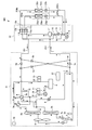
- FIG. 1 is a diagram illustrating a refrigerant circuit of an air-conditioning apparatus according to Embodiment 1 of the present invention.
- the circuit configuration of the air conditioner 500 will be described based on FIG.
- the air conditioner 500 performs a cooling operation and a heating operation using a refrigeration cycle such as a heat pump cycle for circulating a refrigerant.
- the air conditioning apparatus 500 illustrated in FIG. 1 is merely an example, and may include two or more outdoor units or a plurality of load-side units.
- the air conditioner 500 includes one outdoor unit 51 and two indoor units 53a and 53b. And the outdoor unit 51 is connected to the two indoor units 53a and 53b by the low pressure pipe 201 and the high pressure pipe 202, and the refrigerating cycle circuit is comprised.
- the outdoor unit 51 includes a compressor 1, four-way valves 3 a and 3 b, heat source side heat exchangers 2 a and 2 b, heat source side flow rate adjustment valves 7 a and 7 b, a heat source side bypass valve 8, and a distributor 9.
- the pipe in which the heat source side bypass valve 8 is arranged is a first bypass passage that bypasses between the four-way valve 3b and the heat source side heat exchanger 2b and between the heat source side heat exchanger 2b and the indoor side heat exchangers 22a and 22b. It is.
- the heat source side bypass valve 8 corresponds to the first bypass valve of the present invention.
- the heat source side flow rate adjustment valves 7a and 7b correspond to a plurality of flow rate adjustment valves provided in piping in which each of the plurality of heat source side heat exchangers of the present invention is arranged.
- the distributor 9 divides the piping into two so that the heat source side heat exchangers 2a and 2b are arranged in parallel.
- the outdoor unit 51 includes an accumulator 4, check valves 5 a, 5 b, 5 c, 5 d, and the outdoor blower 6. Furthermore, the outdoor unit 51 includes a compressor discharge pressure detection sensor 31, a heat exchanger outlet pressure detection sensor 32, a compressor discharge temperature detection sensor 34, a heat exchanger outlet temperature detection sensor 35, and an outside air temperature detection sensor 36. ing.
- the outdoor unit 51 is provided with a control unit 37 that controls the compressor 1, the four-way valves 3 a and 3 b, the heat source side flow rate adjustment valves 7 a and 7 b, and the heat source side bypass valve 8.
- the controller 37 includes a compressor discharge pressure detection sensor 31, a heat exchanger outlet pressure detection sensor 32, a compressor discharge temperature detection sensor 34, a heat exchanger outlet temperature detection sensor 35, and an outside air temperature detection sensor 36. Connected and these detection values are input.
- the control unit 37 has a microcomputer including a CPU, a ROM, a RAM, an I / O port, and the like.
- Four-way valves 3 a and 3 b are connected to the discharge side of the compressor 1.
- the four-way valves 3a and 3b switch the flow path of the refrigerant discharged from the compressor 1 to a flow path that flows to the heat source side heat exchangers 2a and 2b or a flow path that flows to the indoor units 53a and 53b.
- the four-way valves 3a and 3b are also connected to the accumulator 4 and send the refrigerant flowing from the heat source side heat exchangers 2a and 2b or the indoor units 53a and 53b to the accumulator 4.
- the four-way valves 3a and 3b correspond to the flow path switching device of the present invention.
- the flow path switching device is not limited to a four-way switching valve, and may be configured by combining, for example, a two-way valve.
- the air conditioner 500 includes an outdoor unit 51, a plurality of indoor units 53a and 53b, and a shunt controller 52.
- a shunt controller 52 is provided between the outdoor unit 51 and the indoor units 53a and 53b, and these devices are connected by various refrigerant pipes.
- the plurality of indoor units 53a and 53b are connected in parallel with each other. Note that, for example, in the indoor unit 53a and the indoor unit 53b, when there is no need to particularly distinguish or specify, the subscripts a and b may be omitted below.
- the outdoor unit 51 and the shunt controller 52 are connected by a low pressure pipe 201 and a high pressure pipe 202.
- a high-pressure refrigerant flows from the outdoor unit 51 side to the shunt controller 52 side.
- a refrigerant having a lower pressure flows through the low pressure pipe 201 than the refrigerant flowing through the high pressure pipe 202 from the shunt controller 52 side to the outdoor unit 51.
- the level of the pressure is not determined by the relationship with the pressure such as a reference numerical value.
- the level of the pressure is expressed based on the level including the relative middle in the refrigerant circuit by controlling the opening degree or the open / closed state of each throttle device such as the pressurization of the compressor 1 and the flow rate adjusting device.
- the shunt controller 52 and the indoor unit 53a are connected by a liquid pipe 203a and a gas pipe 204a.
- the diversion controller 52 and the indoor unit 53b are connected by a liquid pipe 203b and a gas pipe 204b.
- the four-way valves 3a and 3b perform valve switching corresponding to a mode that is a mode of air conditioning operation so that the refrigerant path is switched.
- the path is switched between the cooling only operation mode and the cooling main operation mode, and the heating only operation mode and the heating main operation mode.
- the operation when all of the indoor units 53a and 53b that are performing air conditioning are cooling is referred to as a cooling only operation.
- an operation with a large cooling load is referred to as a cooling main operation.
- the operation when all the indoor units 53a and 53b that are performing the air conditioning are heating is referred to as a full heating operation.
- an operation with a large heating load is called a heating-based operation.
- the heat source side heat exchangers 2a and 2b have heat transfer tubes that allow the refrigerant to pass therethrough and fins for increasing the heat transfer area between the refrigerant flowing through the heat transfer tubes and the outside air. Perform heat exchange.
- the heat source side heat exchangers 2a and 2b function as an evaporator during, for example, the all heating operation and the heating main operation, and evaporate and evaporate the refrigerant.
- the heat source side heat exchangers 2a and 2b function as a condenser, for example, during the cooling only operation and the cooling main operation, and condense and liquefy the refrigerant.
- the heat source side heat exchangers 2a and 2b are not completely gasified or liquefied, for example, in the cooling main operation, but are in a gas-liquid two-phase state in which liquid and gas are mixed in two phases. Adjustments such as condensation are performed.
- the check valves 5a, 5b, 5c, and 5d prevent the refrigerant from flowing backward to adjust the flow of the refrigerant, and make the refrigerant circulation path constant according to the mode.
- the check valve 5a is located on the pipe between the four-way valve 3b and the low-pressure pipe 201, and allows the refrigerant flow from the low-pressure pipe 201 to the four-way valve 3b.
- the check valve 5b is located on the pipe between the heat source side heat exchangers 2a, 2b and the low pressure pipe 201, and allows the refrigerant flow from the low pressure pipe 201 toward the heat source side heat exchangers 2a, 2b.
- the check valve 5 c is located on the pipe between the four-way valve 3 b and the high-pressure pipe 202, and allows the refrigerant flow from the four-way valve 3 b to the high-pressure pipe 202.
- the check valve 5d is located on the pipe between the heat source side heat exchangers 2a and 2b and the high pressure pipe 202, and allows the refrigerant flow from the heat source side heat exchangers 2a and 2b to the high pressure pipe 202.
- a compressor discharge pressure detection sensor 31 that detects the pressure of the refrigerant on the discharge side of the compressor 1 is attached on the piping on the discharge side of the compressor 1.
- a heat exchanger outlet pressure detection sensor 32 that detects the pressure of the refrigerant on the outlet side of the heat source side heat exchangers 2a and 2b during heating operation is attached.
- a compressor discharge temperature detection sensor 34 that detects the temperature of the refrigerant on the high pressure side is attached to the piping on the discharge side of the compressor 1.
- a heat exchanger outlet temperature detection sensor 35 for detecting the outlet temperature of the heat source side heat exchangers 2a and 2b is attached to the pipe on the suction side of the compressor 1.
- an outside air temperature detection sensor 36 that detects the ambient temperature of the outdoor unit 51 is attached.
- the diversion controller 52 has the gas-liquid separator 11.
- the gas-liquid separator 11 separates the refrigerant flowing from the high-pressure pipe 202 into a gas refrigerant and a liquid refrigerant.
- a gas phase portion (not shown) from which the gas refrigerant flows out is connected to the electromagnetic valves 12a and 12b.
- a liquid phase portion (not shown) from which the liquid refrigerant flows is connected to the inter-refrigerant heat exchanger 16.
- the electromagnetic valves 12a, 12b, 13a, 13b are opened and closed based on the operation mode.
- One ends of the electromagnetic valves 12 a and 12 b are connected to the gas-liquid separator 11.
- the other ends of the electromagnetic valves 12a and 12b are connected to gas pipes 204a and 204b, respectively.
- one ends of the electromagnetic valves 13a and 13b are connected to the gas pipes 204a and 204b, respectively.
- the other ends of the electromagnetic valves 13 a and 13 b are connected to the low pressure pipe 201.
- the solenoid valves 12a, 12b, 13a, and 13b are combined to allow the refrigerant to flow from the indoor unit 53 side to the low-pressure pipe 201 side based on the operation mode, or from the gas-liquid separator 11 side to the indoor unit.
- the valve is switched so that the refrigerant flows to the 53 side.
- the flow of the refrigerant is switched by the electromagnetic valves 12 and 13.
- a three-way valve or the like may be used instead of the electromagnetic valve.
- the expansion device 14 is provided between the inter-refrigerant heat exchanger 16 and the inter-refrigerant heat exchanger 17.
- the expansion device 14 controls the opening degree based on the operation mode, and adjusts the flow rate of refrigerant flowing from the gas-liquid separator 11 and the pressure of the refrigerant.
- the expansion device 15 controls the opening and adjusts the refrigerant flow rate and the refrigerant pressure.
- the refrigerant that has passed through the expansion device 15 supercools the refrigerant in the inter-refrigerant heat exchanger 17 and the inter-refrigerant heat exchanger 16, for example, and flows to the low-pressure pipe 201.
- the inter-refrigerant heat exchanger 17 performs heat exchange between the refrigerant in the downstream portion of the expansion device 15 that has passed through the expansion device 15 and the refrigerant flowing from the expansion device 14.
- the inter-refrigerant heat exchanger 16 exchanges heat between the refrigerant that has passed through the inter-refrigerant heat exchanger 17 and the liquid refrigerant that flows from the gas-liquid separator 11 toward the expansion device 14.
- the indoor unit 53a includes an indoor side heat exchanger 22a and an indoor side expansion device 23a connected in series in proximity to the indoor side heat exchanger 22a.
- the indoor unit 53b has an indoor side heat exchanger 22b and an indoor side expansion device 23b connected in series in proximity to the indoor side heat exchanger 22b.
- the indoor side heat exchanger 22 serves as an evaporator during cooling operation, and serves as a condenser during heating operation, and exchanges heat between air and refrigerant in the air-conditioning target space. I do. Here, you may provide the air blower which performs the heat exchange with a refrigerant
- the indoor side expansion device 23 functions as a pressure reducing valve or an expansion valve, and adjusts the pressure of the refrigerant passing through the indoor side heat exchanger 22.
- the indoor expansion device 23 according to Embodiment 1 is configured with, for example, an electronic expansion valve that can change the opening degree.
- the opening degree of the indoor expansion device 23 is determined based on the degree of superheat on the refrigerant outlet side of the indoor heat exchanger 22 on the gas pipe 204 side during the cooling operation. Further, the opening degree of the indoor expansion device 23 is determined based on the degree of supercooling on the refrigerant outlet side of the indoor heat exchanger 22 on the liquid pipe 203 side during heating operation.
- the air conditioner 500 configured as described above can be operated in any one of the four modes of the cooling only operation, the heating only operation, the cooling main operation, and the heating main operation.
- FIG. 2 is a diagram showing a refrigerant flow in the heating only operation of the air-conditioning apparatus 500 according to Embodiment 1 of the present invention.
- the operation of each device and the flow of refrigerant in the heating only operation will be described.
- the flow of the refrigerant during the all-heating operation is indicated by solid line arrows in FIG.
- the outdoor unit 51 the refrigerant sucked by the compressor 1 is compressed and high-pressure gas refrigerant is discharged.
- the refrigerant discharged from the compressor 1 flows through the four-way valve 3b and the check valve 5c, and does not flow to the check valve 5a and check valve 5d side due to the refrigerant pressure.
- the refrigerant that has flowed through the check valve 5 c flows into the branch flow controller 52 through the high-pressure pipe 202.
- the solenoid valves 12a and 12b are opened, and the solenoid valves 13a and 13b are closed.
- the gas refrigerant that has flowed into the diversion controller 52 passes through the gas-liquid separator 11, the electromagnetic valves 12a and 12b, and the gas pipes 204a and 204b, and flows into the indoor units 53a and 53b.
- the flow rate of the refrigerant flowing through the indoor heat exchangers 22a and 22b is adjusted by adjusting the opening of the indoor expansion devices 23a and 23b.
- the high-pressure gas refrigerant is condensed by heat exchange while passing through the indoor heat exchangers 22a and 22b, and passes through the indoor expansion devices 23a and 23b.
- the room air is heated by heat exchange to heat the room that is the air-conditioning target space.
- the refrigerant that has passed through the indoor expansion devices 23a and 23b becomes, for example, an intermediate-pressure liquid refrigerant or a gas-liquid two-phase refrigerant, passes through the liquid pipes 203a and 203b, flows to the inter-refrigerant heat exchanger 17, and passes through the expansion device 15. pass.
- the expansion device 15 the refrigerant is decompressed.
- the refrigerant that has been reduced in pressure after passing through the expansion device 15 flows into the low-pressure pipe 201 and flows into the outdoor unit 51.
- the refrigerant flowing into the outdoor unit 51 passes through the check valve 5b of the outdoor unit 51, is divided into two pipes by the distributor 9, passes through the heat source side flow rate adjusting valves 7a, 7b, and then the heat source side heat exchanger 2a. 2b.
- the refrigerant flowing into the heat source side heat exchangers 2a and 2b evaporates into a gas refrigerant by heat exchange with air while passing through the heat source side heat exchangers 2a and 2b.
- the gas refrigerant passes through the four-way valves 3a and 3b and the accumulator 4, and returns to the compressor 1 to be discharged again. This is the refrigerant circulation path during the all-heating operation.
- on-defrost there are two cases: defrosting the heat source side heat exchanger 2a and defrosting the heat source side heat exchanger 2b.
- the case where the heat source side heat exchanger 2b is defrosted is referred to as a first on defrost
- the case where the heat source side heat exchanger 2a is defrosted is referred to as a second on defrost.
- FIG. 3 is a diagram showing a refrigerant flow in the first on-defrost operation of the air-conditioning apparatus 500 according to Embodiment 1 of the present invention.
- FIG. 4 is a Ph diagram illustrating the change of the refrigerant in the first on-defrost operation of the air-conditioning apparatus 500 according to Embodiment 1 of the present invention.
- the refrigerant sucked by the compressor 1 is compressed and high-pressure gas refrigerant is discharged.
- the refrigerant discharged from the compressor 1 passes through the four-way valve 3b and is divided into a refrigerant flowing through the heat source side heat exchanger 2b and a refrigerant flowing through the heat source side bypass valve 8.
- the refrigerant flowing to the heat source side heat exchanger 2b can flow a high-temperature and high-pressure gas refrigerant, and the refrigerant kept at a high condensation temperature can be flowed to the heat source side heat exchanger 2b for defrosting. growing.
- the opening degree of the heat source side bypass valve 8 is set to a predetermined opening degree C1.
- the refrigerant that has flowed to the heat source side bypass valve 8 is divided into the refrigerant that flows to the heat source side heat exchanger 2a and the refrigerant that flows to the check valve 5d.
- the refrigerant flowing through the heat source side heat exchanger 2b passes through the heat source side flow rate adjusting valve 7b, merges with the refrigerant flowing through the heat source side bypass valve 8, and evaporates as shown in FIGS.
- the valve opening degree of the heat source side flow rate adjustment valve 7a is set to a predetermined opening degree A1.
- the valve opening degree of the heat source side flow rate adjustment valve 7b is set to a predetermined opening degree B1.
- the refrigerant that has flowed into the check valve 5d flows into the flow dividing controller 52 through the high-pressure pipe 202.
- the solenoid valves 12a and 12b are opened, and the solenoid valves 13a and 13b are closed.
- the gas refrigerant that has flowed into the diversion controller 52 passes through the gas-liquid separator 11, the electromagnetic valves 12a and 12b, and the gas pipes 204a and 204b, and flows into the indoor units 53a and 53b.
- the flow rate of the refrigerant flowing through the indoor heat exchangers 22a and 22b is adjusted by adjusting the opening of the indoor expansion devices 23a and 23b.
- the high-pressure gas refrigerant is condensed by heat exchange while passing through the indoor heat exchangers 22a and 22b, and passes through the indoor expansion devices 23a and 23b.
- the refrigerant passing through the indoor heat exchangers 22a and 22b heats the indoor air by heat exchange and heats the indoor air conditioning target space.
- the refrigerant that has passed through the indoor expansion devices 23a and 23b becomes, for example, an intermediate-pressure liquid refrigerant or a gas-liquid two-phase refrigerant, passes through the liquid pipes 203a and 203b, flows to the inter-refrigerant heat exchanger 17, and passes through the expansion device 15. pass.
- the expansion device 15 the refrigerant is decompressed.
- the refrigerant that has been reduced in pressure after passing through the expansion device 15 flows into the low-pressure pipe 201 and flows into the outdoor unit 51.
- the refrigerant that has flowed into the outdoor unit 51 passes through the check valve 5a of the outdoor unit 51 and passes through the four-way valve 3b.
- the refrigerant flowing into the heat source side heat exchanger 2a through the heat source side flow rate adjusting valve 7a merges with the refrigerant that passes through the heat source side heat exchanger 2b and then passes through the heat source side heat exchanger 2b, and evaporates. It becomes a refrigerant and passes through the heat source side heat exchanger 2a and the four-way valve 3a.
- the refrigerant that has passed through the check valve 5a and passed through the four-way valve 3b and the refrigerant that has passed through the heat source side heat exchanger 2a join together, as shown in (i) to (f) of FIG. It evaporates, passes through the accumulator 4, returns to the compressor 1 and is discharged again. This is the circulation path of the first on-defrost refrigerant.
- the compressor 1, the four-way valve 3b, the heat source side heat exchanger 2b for performing the defrosting, and the heat source side A defrost circuit is configured by connecting the flow rate adjusting valve 7b with a pipe.
- the compressor 1, the four-way valve 3b, the indoor heat exchanger 22 and the indoor expansion device 23 are connected by piping to form a heating circuit.
- FIG. 5 is a diagram showing a refrigerant flow in the second on-defrost operation of the air-conditioning apparatus 500 according to Embodiment 1 of the present invention.
- FIG. 6 is a Ph diagram showing the change of the refrigerant in the second on-defrost operation of the air-conditioning apparatus 500 according to Embodiment 1 of the present invention.
- the refrigerant sucked by the compressor 1 is compressed and high-pressure gas refrigerant is discharged.
- the refrigerant discharged from the compressor 1 is divided into the four-way valve 3a and the four-way valve 3b.
- the refrigerant that has flowed to the four-way valve 3b flows through the check valve 5c and does not flow toward the check valve 5a and the check valve 5d due to the refrigerant pressure.
- the refrigerant that has flowed through the check valve 5 c flows into the branch flow controller 52 through the high-pressure pipe 202.
- the refrigerant that has flowed to the four-way valve 3a passes through the heat source side heat exchanger 2a, passes through the heat source side flow rate adjustment valve 7a, passes through the distributor 9 and passes through the heat source side flow rate adjustment valve 7b.
- the refrigerant flowing through the heat source side heat exchanger 2a can flow a high-temperature and high-pressure gas refrigerant, and the refrigerant kept at a high condensation temperature can be flowed to the heat source side heat exchanger 2a for defrosting. growing.
- the opening degree of the heat source side flow rate adjustment valve 7a is a predetermined opening degree A2
- the opening degree of the heat source side flow rate adjustment valve 7b is a predetermined opening degree B2.
- the opening degree of the heat source side bypass valve 8 is set to a predetermined opening degree C2.
- the solenoid valves 12a and 12b are opened, and the solenoid valves 13a and 13b are closed.
- the gas refrigerant that has flowed into the diversion controller 52 passes through the gas-liquid separator 11, the electromagnetic valves 12a and 12b, and the gas pipes 204a and 204b, and flows into the indoor units 53a and 53b.
- the flow rate of the refrigerant flowing through the indoor heat exchangers 22a and 22b is adjusted by adjusting the opening of the indoor expansion devices 23a and 23b.
- the high-pressure gas refrigerant is condensed by heat exchange while passing through the indoor heat exchangers 22a and 22b, and passes through the indoor expansion devices 23a and 23b.
- the indoor air is heated to heat the room, which is the air-conditioning target space, by heat exchange while passing through the indoor heat exchangers 22a and 22b.
- the refrigerant that has passed through the indoor expansion devices 23a and 23b becomes, for example, an intermediate-pressure liquid refrigerant or a gas-liquid two-phase refrigerant, passes through the liquid pipes 203a and 203b, flows to the inter-refrigerant heat exchanger 17, and passes through the expansion device 15. pass.
- the expansion device 15 the refrigerant is decompressed.
- the refrigerant that has been reduced in pressure after passing through the expansion device 15 flows into the low-pressure pipe 201 and flows into the outdoor unit 51.
- the refrigerant that has flowed into the outdoor unit 51 passes through the check valve 5b of the outdoor unit 51, merges with the refrigerant that has passed through the heat source side heat exchanger 2a in the distributor 9, and passes through the heat source side flow rate adjustment valve 7b. It flows into the heat source side heat exchanger 2b. While passing through the heat source side heat exchanger 2b, the refrigerant evaporates by heat exchange with air and becomes a gas refrigerant. And it returns to the compressor 1 again through the four-way valve 3b and the accumulator 4, and is discharged. This is the circulation path of the second on-defrost refrigerant.
- the compressor 1, the four-way valve 3a, the heat source side heat exchanger 2a for performing the defrosting, and the heat source side A defrost circuit is configured by connecting the flow rate adjusting valve 7a with a pipe.
- the compressor 1, the four-way valve 3b, the indoor heat exchanger 22 and the indoor expansion device 23 are connected by piping to form a heating circuit.
- FIG. 7 is a flowchart showing operation mode control of the air-conditioning apparatus 500 according to Embodiment 1 of the present invention.
- the control flow shown in FIG. 7 according to Embodiment 1 will be described.
- the control unit 37 determines whether or not the heating continuous operation time Time1 has passed the predetermined time Z1 (S1).
- the control unit 37 next determines whether the heat exchanger inlet temperature T33 is lower than the predetermined temperature T1 by the heat exchanger inlet temperature detection sensor 33. Is determined (S2). That is, S2 detects whether the heat source side heat exchanger 2 needs to be defrosted based on the inlet temperature of the heat source side heat exchanger 2 during the heating only operation.
- the controller 37 starts the first on-defrost when it is determined in S2 that the heat exchange inlet temperature T33 is lower than the predetermined temperature T1 (S3).
- the control unit 37 switches the four-way valve 3b (S4), sets the opening degree of the heat source side flow rate adjustment valve 7a to A1, sets the opening degree of the heat source side flow rate adjustment valve 7b to B1, and sets the opening degree of the heat source side bypass valve 8 to C1. (S5).
- the controller 37 determines whether or not the compressor discharge pressure Pd is smaller than a predetermined pressure P1 by the compressor discharge pressure detection sensor 31 (S6).
- the control unit 37 determines that the heating capacity is insufficient when the compressor discharge pressure Pd is smaller than the predetermined pressure P1, opens the predetermined amount ⁇ C of the heat source side bypass valve 8, and increases the refrigerant flowing to the indoor unit 53 side. (S7). That is, when a lack of indoor heating capacity is detected based on the compressor discharge pressure Pd of the compressor 1, the heat source side bypass valve 8 increases the amount of refrigerant circulating in the heating circuit by adjusting the opening.
- the control unit 37 determines whether or not the compressor suction pressure Ps is smaller than the predetermined pressure P2 by the heat exchanger outlet pressure detection sensor 32 (S8). When the compressor suction pressure Ps is smaller than the predetermined pressure P2, the control unit 37 determines that the evaporation capacity on the outdoor unit 51 side is insufficient, and opens the opening of the heat source side flow rate adjustment valve 7a by a predetermined amount ⁇ A (S9). ).
- the control unit 37 determines whether or not the on-defrost operation time Time2 has passed a predetermined time Z2 (S10).
- the control unit 37 determines that the defrosting of the heat source side heat exchanger 2b is completed, and shifts to the second on-defrost (S11).
- the control unit 37 switches the four-way valves 3a and 3b (S12), the opening degree of the heat source side flow rate adjustment valve 7a is set to A2, the opening degree of the heat source side flow rate adjustment valve 7b is set to B2, and the opening degree of the heat source side bypass valve 8 is set. Is C2 (S13).
- the control unit 37 determines whether or not the compressor discharge pressure Pd is smaller than the predetermined pressure P1 by the compressor discharge pressure detection sensor 31 (S14).
- the control unit 37 determines that the heating capacity is insufficient, closes the opening of the heat source side flow rate adjustment valve 7a by a predetermined amount ⁇ A, and flows into the indoor unit 53 side. Is increased (S15). That is, when a lack of indoor heating capacity is detected based on the compressor discharge pressure Pd of the compressor 1, the heat source side flow rate adjustment valve 7a increases the amount of refrigerant circulating in the heating circuit by adjusting the opening.
- the control unit 37 determines whether or not the compressor suction pressure Ps is smaller than a predetermined pressure P2 by the heat exchanger outlet pressure detection sensor 32 (S16). When the compressor suction pressure Ps is smaller than the predetermined pressure P2, the control unit 37 determines that the evaporation capacity on the outdoor unit 51 side is insufficient, and opens the opening of the heat source side flow rate adjustment valve 7b by a predetermined amount ⁇ B (S17). ).
- the control unit 37 determines whether or not the on-defrost operation time Time3 has passed a predetermined time Z3 (S18).
- the control unit 37 determines that the defrosting of the heat source side heat exchanger 2a is completed, ends the on-defrost operation, and shifts to the heating only operation. Therefore, the four-way valves 3a and 3b are switched (S19).
- the control unit 37 sets the opening degree of the heat source side flow rate adjustment valve 7a to A3, sets the opening degree of the heat source side flow rate adjustment valve 7b to B3, and sets the opening degree of the heat source side flow rate adjustment valve 8 to C3 (S20). Control of on-defrost operation is completed in one cycle.
- FIG. 8 is a diagram illustrating a case where hot gas is allowed to flow in the first on-defrost operation of the air-conditioning apparatus 500 according to Embodiment 1 of the present invention.
- a countermeasure when the refrigerant is not evaporated during the first on-defrost operation and returns to the compressor 1 will be described.
- the flow of the refrigerant is indicated by solid line arrows shown in FIG.
- the refrigerant that has passed through the check valve 5a after condensing in the indoor heat exchanger 22 passes through the heat source side heat exchanger 2 as shown in FIGS. Without flowing to the accumulator 4.
- the liquid refrigerant gradually accumulates in the accumulator 4 and may overflow.
- the outdoor unit 51 includes an accumulator 4 disposed in a pipe on the upstream side of the compressor 1 and a second bypass that distributes the refrigerant on the discharge side of the compressor 1 to the pipe on the upstream side of the accumulator 4.
- a pipe having a hot gas bypass valve 10 as a passage is disposed.
- the hot gas bypass valve 10 corresponds to the second bypass valve of the present invention.
- the control unit 37 includes a refrigerant evaporation temperature converted by the heat exchanger outlet pressure detected by the heat exchanger outlet pressure detection sensor 32, a heat exchanger outlet temperature detected by the heat exchanger outlet temperature detection sensor 35, and Thus, the concern about the overflow of the liquid refrigerant is determined.
- the control unit 37 When the control unit 37 detects that the liquid refrigerant overflows, the control unit 37 opens the hot gas bypass valve 10 and causes the compressor discharge side refrigerant to flow through the pipe provided with the hot gas bypass valve 10.
- the refrigerant that has passed through the pipe provided with the hot gas bypass valve 10 merges with the refrigerant that has passed through the check valve 5a, evaporates the condensed refrigerant by using the amount of refrigerant heat compressed by the compressor 1, and the liquid refrigerant Overflow is prevented.
- adopted for an air conditioning apparatus is not specifically limited,
- coolants such as R410A, R32, R407C, R404A, HFO1234yf, are used from natural refrigerant
- the air conditioner 500 includes the compressor 1, the four-way valves 3a and 3b, the plurality of heat source side heat exchangers 2a and 2b, the heat source side flow rate adjusting valves 7a and 7b, and the heat source side bypass valve 8. It has the outdoor unit 51 which has.
- An indoor unit having indoor heat exchangers 22a and 22b and indoor expansion devices 23a and 23b is provided. During the execution of the first on-defrost or the second on-defrost in which the defrosting of one of the heat source side heat exchangers 2a, 2b and the indoor heating are operated in parallel among the plurality of heat source side heat exchangers 2a, 2b.
- Machine 1 four-way valves 3a, 3b, heat source side heat exchangers 2a, 2b for performing defrosting of any of heat source side heat exchangers 2a, 2b, heat source side flow rate adjusting valves 7a, 7b and heat source side bypass valves 8 is connected to form a defrost circuit.
- the compressor 1, the four-way valves 3a and 3b, the indoor heat exchangers 22a and 22b, and the indoor expansion devices 23a and 23b are connected to form a heating circuit.
- the heat source side flow rate adjustment valves 7a and 7b and the heat source side bypass valve 8 increase or decrease the amount of refrigerant circulating in either the defrost circuit or the heating circuit by adjusting the opening. Is configured to do.
- the gas refrigerant discharged from the compressor 1 is divided into the refrigerant flowing in the indoor heat exchangers 22a and 22b and the refrigerant flowing in the heat source side heat exchangers 2a and 2b to be defrosted,
- the first on-defrost or the second on-defrost is performed to defrost the heat source side heat exchangers 2a and 2b while performing the heating operation.
- the heat source side heat exchangers 2a and 2b and the indoor side heat to be defrosted by adjusting the opening degree of the heat source side flow rate adjusting valves 7a and 7b and the heat source side bypass valve 8 during execution of the first on defrost or the second on defrost.
- the refrigerant circulation amount that is diverted to the exchangers 22a and 22b can be increased or decreased. Therefore, when the amount of frost formation is small, a large amount of refrigerant flows through the indoor heat exchangers 22a and 22b, so that the heating capacity can be improved. When the amount of frost formation is large, a large amount of refrigerant flows through the heat source side heat exchangers 2a and 2b to be defrosted so that defrosting can be performed reliably.
- the outdoor unit 51 has a first bypass passage that bypasses between the four-way valve 3b and the heat source side heat exchanger 2b and between the heat source side heat exchanger 2b and the indoor side heat exchangers 22a and 22b.
- the heat source side flow rate adjusting valves 7a and 7b and the heat source side bypass valve 8 are provided in a pipe in which each of the heat source side bypass valve 8 provided in the first bypass passage and the plurality of heat source side heat exchangers 2a and 2b is arranged. Heat source side flow rate regulating valves 7a, 7b.
- the heat source side heat exchangers 2a and 2b to be defrosted by adjusting the opening degrees of the heat source side flow rate adjusting valves 7a and 7b and the heat source side bypass valve 8 during execution of the first on defrost or the second on defrost. And the amount of refrigerant circulating in the indoor heat exchangers 22a and 22b can be increased or decreased.
- the heat source side bypass valve 8 or the heat source side flow rate adjustment valve 7a adjusts the degree of opening so that the amount of refrigerant circulating in the heating circuit Is configured to increase. According to this configuration, the lack of room heating capacity is solved during execution of the first on-defrost or the second on-defrost.
- the heat source side heat exchangers 2a and 2b are configured to detect whether or not defrosting is necessary based on the inlet temperatures of the heat source side heat exchangers 2a and 2b. According to this configuration, it is possible to appropriately determine the execution opportunity of the first on-defrost or the second on-defrost.
- the outdoor unit 51 includes an accumulator 4 disposed in a pipe on the upstream side of the compressor 1, a pipe for circulating the refrigerant on the discharge side of the compressor 1 through a pipe on the upstream side of the accumulator 4, and a hot provided in the pipe And a gas bypass valve 10. Hot gas bypass when a liquid refrigerant overflow concern of the accumulator 4 is detected based on the heat exchanger outlet pressure of the heat source side heat exchangers 2a and 2b and the heat exchanger outlet temperature of the heat source side heat exchangers 2a and 2b.
- the valve 10 is configured to prevent overflow of the liquid refrigerant in the accumulator 4 by opening the valve to evaporate the refrigerant using the amount of heat of the refrigerant.
- the hot gas bypass valve 10 is opened to cause the refrigerant to evaporate using the amount of refrigerant heat, thereby overflowing the liquid refrigerant in the accumulator 4. Can be prevented.
Landscapes
- Engineering & Computer Science (AREA)
- Mechanical Engineering (AREA)
- General Engineering & Computer Science (AREA)
- Physics & Mathematics (AREA)
- Thermal Sciences (AREA)
- Chemical & Material Sciences (AREA)
- Combustion & Propulsion (AREA)
- Analytical Chemistry (AREA)
- Power Engineering (AREA)
- Air Conditioning Control Device (AREA)
Abstract
L'invention vise à augmenter ou à diminuer la quantité de fluide frigorigène circulant qui est déviée vers un échangeur de chaleur intérieur et un échangeur de chaleur côté source de chaleur qui est dégivré par augmentation ou diminution du degré d'ouverture d'une soupape de régulation de débit côté source de chaleur alors qu'un dégivrage est en cours, pour améliorer la performance de chauffage lorsqu'une faible quantité de givre est formée, et qui permet le dégivrage de manière fiable lorsqu'une grande quantité de givre est formée. Un dispositif de climatisation forme un circuit de dégivrage et forme un circuit de chauffage alors que le dégivrage est en cours. Dans un état où le dégivrage est en cours, la soupape de régulation de débit côté source de chaleur est conçue pour augmenter ou réduire la quantité de fluide frigorigène circulant dans le circuit de dégivrage ou le circuit de chauffage par réglage du degré d'ouverture de la soupape.
Priority Applications (1)
| Application Number | Priority Date | Filing Date | Title |
|---|---|---|---|
| PCT/JP2016/053942 WO2017138108A1 (fr) | 2016-02-10 | 2016-02-10 | Dispositif de climatisation |
Applications Claiming Priority (1)
| Application Number | Priority Date | Filing Date | Title |
|---|---|---|---|
| PCT/JP2016/053942 WO2017138108A1 (fr) | 2016-02-10 | 2016-02-10 | Dispositif de climatisation |
Publications (1)
| Publication Number | Publication Date |
|---|---|
| WO2017138108A1 true WO2017138108A1 (fr) | 2017-08-17 |
Family
ID=59563011
Family Applications (1)
| Application Number | Title | Priority Date | Filing Date |
|---|---|---|---|
| PCT/JP2016/053942 WO2017138108A1 (fr) | 2016-02-10 | 2016-02-10 | Dispositif de climatisation |
Country Status (1)
| Country | Link |
|---|---|
| WO (1) | WO2017138108A1 (fr) |
Cited By (7)
| Publication number | Priority date | Publication date | Assignee | Title |
|---|---|---|---|---|
| JP6661843B1 (ja) * | 2019-03-25 | 2020-03-11 | 三菱電機株式会社 | 空気調和装置 |
| WO2020121411A1 (fr) * | 2018-12-11 | 2020-06-18 | 三菱電機株式会社 | Climatiseur |
| CN112443999A (zh) * | 2020-11-30 | 2021-03-05 | 青岛海信日立空调系统有限公司 | 一种空调器 |
| CN112628941A (zh) * | 2020-12-11 | 2021-04-09 | 珠海格力电器股份有限公司 | 一种空调化霜控制方法、装置、存储介质及空调 |
| WO2021124458A1 (fr) | 2019-12-17 | 2021-06-24 | 三菱電機株式会社 | Dispositif à cycle de réfrigération |
| WO2021218350A1 (fr) * | 2020-04-30 | 2021-11-04 | 青岛海尔空调电子有限公司 | Procédé de commande de système de climatisation et système de climatisation |
| CN113710971A (zh) * | 2019-04-11 | 2021-11-26 | 三菱电机株式会社 | 空气调节装置 |
Citations (9)
| Publication number | Priority date | Publication date | Assignee | Title |
|---|---|---|---|---|
| JPS5634074A (en) * | 1979-08-27 | 1981-04-06 | Hitachi Ltd | Air conditioner with airrcooled heat pump |
| JPH035680A (ja) * | 1989-05-30 | 1991-01-11 | Sharp Corp | 空気調和機 |
| JPH06174343A (ja) * | 1992-12-03 | 1994-06-24 | Hitachi Ltd | 冷凍・冷蔵ユニットの除霜サイクル |
| JPH071954A (ja) * | 1993-04-23 | 1995-01-06 | Nippondenso Co Ltd | 電気自動車用空気調和装置 |
| JPH09138025A (ja) * | 1995-11-14 | 1997-05-27 | Mitsubishi Electric Corp | 蓄熱式空気調和装置 |
| WO2010082325A1 (fr) * | 2009-01-15 | 2010-07-22 | 三菱電機株式会社 | Appareil de conditionnement d'air |
| JP2010271011A (ja) * | 2009-05-25 | 2010-12-02 | Mitsubishi Electric Corp | 空気調和機 |
| JP2011080741A (ja) * | 2009-09-09 | 2011-04-21 | Fujitsu General Ltd | ヒートポンプ装置 |
| JP2012083065A (ja) * | 2010-10-14 | 2012-04-26 | Panasonic Corp | 空気調和機 |
-
2016
- 2016-02-10 WO PCT/JP2016/053942 patent/WO2017138108A1/fr active Application Filing
Patent Citations (9)
| Publication number | Priority date | Publication date | Assignee | Title |
|---|---|---|---|---|
| JPS5634074A (en) * | 1979-08-27 | 1981-04-06 | Hitachi Ltd | Air conditioner with airrcooled heat pump |
| JPH035680A (ja) * | 1989-05-30 | 1991-01-11 | Sharp Corp | 空気調和機 |
| JPH06174343A (ja) * | 1992-12-03 | 1994-06-24 | Hitachi Ltd | 冷凍・冷蔵ユニットの除霜サイクル |
| JPH071954A (ja) * | 1993-04-23 | 1995-01-06 | Nippondenso Co Ltd | 電気自動車用空気調和装置 |
| JPH09138025A (ja) * | 1995-11-14 | 1997-05-27 | Mitsubishi Electric Corp | 蓄熱式空気調和装置 |
| WO2010082325A1 (fr) * | 2009-01-15 | 2010-07-22 | 三菱電機株式会社 | Appareil de conditionnement d'air |
| JP2010271011A (ja) * | 2009-05-25 | 2010-12-02 | Mitsubishi Electric Corp | 空気調和機 |
| JP2011080741A (ja) * | 2009-09-09 | 2011-04-21 | Fujitsu General Ltd | ヒートポンプ装置 |
| JP2012083065A (ja) * | 2010-10-14 | 2012-04-26 | Panasonic Corp | 空気調和機 |
Cited By (17)
| Publication number | Priority date | Publication date | Assignee | Title |
|---|---|---|---|---|
| JPWO2020121411A1 (ja) * | 2018-12-11 | 2021-05-20 | 三菱電機株式会社 | 空気調和装置 |
| WO2020121411A1 (fr) * | 2018-12-11 | 2020-06-18 | 三菱電機株式会社 | Climatiseur |
| CN113167517A (zh) * | 2018-12-11 | 2021-07-23 | 三菱电机株式会社 | 空调装置 |
| CN113614463A (zh) * | 2019-03-25 | 2021-11-05 | 三菱电机株式会社 | 空调装置 |
| US11920841B2 (en) | 2019-03-25 | 2024-03-05 | Mitsubishi Electric Corporation | Air-conditioning apparatus |
| SE545954C2 (en) * | 2019-03-25 | 2024-03-26 | Mitsubishi Electric Corp | An air-conditioning apparatus comprising a plurality of parallel heat exchangers and configured to adjust the refrigerant flow rate to defrost one of said heat exchangers |
| WO2020194435A1 (fr) * | 2019-03-25 | 2020-10-01 | 三菱電機株式会社 | Dispositif de climatisation |
| JP6661843B1 (ja) * | 2019-03-25 | 2020-03-11 | 三菱電機株式会社 | 空気調和装置 |
| AU2019436796B2 (en) * | 2019-03-25 | 2022-12-08 | Mitsubishi Electric Corporation | Air-conditioning apparatus |
| CN113614463B (zh) * | 2019-03-25 | 2022-11-08 | 三菱电机株式会社 | 空调装置 |
| CN113710971A (zh) * | 2019-04-11 | 2021-11-26 | 三菱电机株式会社 | 空气调节装置 |
| CN113710971B (zh) * | 2019-04-11 | 2023-02-17 | 三菱电机株式会社 | 空气调节装置 |
| WO2021124458A1 (fr) | 2019-12-17 | 2021-06-24 | 三菱電機株式会社 | Dispositif à cycle de réfrigération |
| WO2021218350A1 (fr) * | 2020-04-30 | 2021-11-04 | 青岛海尔空调电子有限公司 | Procédé de commande de système de climatisation et système de climatisation |
| CN112443999A (zh) * | 2020-11-30 | 2021-03-05 | 青岛海信日立空调系统有限公司 | 一种空调器 |
| CN112628941B (zh) * | 2020-12-11 | 2022-02-18 | 珠海格力电器股份有限公司 | 一种空调化霜控制方法、装置、存储介质及空调 |
| CN112628941A (zh) * | 2020-12-11 | 2021-04-09 | 珠海格力电器股份有限公司 | 一种空调化霜控制方法、装置、存储介质及空调 |
Similar Documents
| Publication | Publication Date | Title |
|---|---|---|
| JP6351848B2 (ja) | 冷凍サイクル装置 | |
| WO2017138108A1 (fr) | Dispositif de climatisation | |
| KR101096822B1 (ko) | 냉동장치 | |
| US8302413B2 (en) | Air conditioner | |
| US20150059380A1 (en) | Air-conditioning apparatus | |
| WO2013145006A1 (fr) | Dispositif de conditionnement d'air | |
| JP6223469B2 (ja) | 空気調和装置 | |
| KR20150074640A (ko) | 공기조화 시스템 및 그 제어방법 | |
| JPH1068553A (ja) | 空気調和機 | |
| JP5258197B2 (ja) | 空気調和システム | |
| JP5235925B2 (ja) | 冷凍装置 | |
| JP5734205B2 (ja) | 空気調和装置 | |
| WO2018078810A1 (fr) | Climatiseur | |
| JP6246394B2 (ja) | 空気調和装置 | |
| JP5855284B2 (ja) | 空気調和装置 | |
| JP6017048B2 (ja) | 空気調和装置 | |
| JP2010048506A (ja) | マルチ型空気調和機 | |
| US20150168037A1 (en) | Air-conditioning apparatus | |
| JP6643630B2 (ja) | 空気調和装置 | |
| JP6539560B2 (ja) | 空気調和装置 | |
| KR101872783B1 (ko) | 실외 열교환기 | |
| JP2006090683A (ja) | 多室型空気調和機 | |
| WO2015029223A1 (fr) | Climatiseur | |
| JPH10176869A (ja) | 冷凍サイクル装置 | |
| KR101692243B1 (ko) | 캐스캐이드 사이클을 이용한 히트 펌프 |
Legal Events
| Date | Code | Title | Description |
|---|---|---|---|
| 121 | Ep: the epo has been informed by wipo that ep was designated in this application |
Ref document number: 16889810 Country of ref document: EP Kind code of ref document: A1 |
|
| NENP | Non-entry into the national phase |
Ref country code: DE |
|
| 122 | Ep: pct application non-entry in european phase |
Ref document number: 16889810 Country of ref document: EP Kind code of ref document: A1 |
|
| NENP | Non-entry into the national phase |
Ref country code: JP |