WO2017138083A1 - Réfractomètre à bloc v - Google Patents
Réfractomètre à bloc v Download PDFInfo
- Publication number
- WO2017138083A1 WO2017138083A1 PCT/JP2016/053707 JP2016053707W WO2017138083A1 WO 2017138083 A1 WO2017138083 A1 WO 2017138083A1 JP 2016053707 W JP2016053707 W JP 2016053707W WO 2017138083 A1 WO2017138083 A1 WO 2017138083A1
- Authority
- WO
- WIPO (PCT)
- Prior art keywords
- processing unit
- refractive index
- data acquisition
- light intensity
- sample
- Prior art date
Links
Images


Classifications
-
- G—PHYSICS
- G01—MEASURING; TESTING
- G01N—INVESTIGATING OR ANALYSING MATERIALS BY DETERMINING THEIR CHEMICAL OR PHYSICAL PROPERTIES
- G01N21/00—Investigating or analysing materials by the use of optical means, i.e. using sub-millimetre waves, infrared, visible or ultraviolet light
- G01N21/17—Systems in which incident light is modified in accordance with the properties of the material investigated
- G01N21/41—Refractivity; Phase-affecting properties, e.g. optical path length
- G01N21/4133—Refractometers, e.g. differential
Definitions
- the present invention relates to a V-block type refractive index measuring apparatus that measures the refractive index of a sample by irradiating the sample with measurement light via a V-block prism.
- a sample is placed in a V-shaped groove formed in a V block prism, and the sample is irradiated with measurement light via the V block prism.
- the measurement light transmitted through the sample can be detected by a detector, and the refractive index of the sample can be measured (for example, see Patent Document 1 below).
- part of the measurement light that is transmitted to the detector through the sample is separated by, for example, a beam splitter and guided to an eyepiece (not shown).
- a beam splitter When adjusting the position of the V block prism, the operator can perform the work while viewing the state of the measurement light by looking into the apparatus from the eyepiece.
- a cap is placed on the eyepiece during measurement in order to prevent light outside the device from entering the eyepiece during measurement and affecting the detection result of the detector. Covered. Therefore, there is a problem that the actual state of the measurement light cannot be observed during the measurement.
- Patent Document 2 proposes a configuration in which a graph representing the detection intensity of measurement light detected by a detector and an image of measurement light captured by a camera are displayed in real time on one display screen. ing.
- the refractive index of the sample is automatically calculated from the peak value of the detection intensity of the measurement light detected by the detector.
- the refractive index of the sample may be nonuniform. Many. Even in such a case, if a refractive index measuring apparatus equipped with a camera as described above is used, the operator determines the state of the sample or the quality of the measurement result by confirming the shape of the graph and the image of the camera. It becomes possible.
- the present invention has been made in view of the above circumstances, and an object of the present invention is to provide a V-block type refractive index measuring device that can easily and accurately determine the quality of the measured refractive index of a sample. .
- a V block type refractive index measuring apparatus is a V block type refractive index measuring apparatus that measures the refractive index of a sample by irradiating the sample with measurement light via a V block prism.
- the light source unit emits measurement light.
- the slit passes through the measurement light emitted from the light source unit.
- the measurement light that has passed through the slit enters the camera.
- the detector detects measurement light transmitted through the sample.
- the first data acquisition processing unit acquires light intensity distribution data based on an image of measurement light incident on the camera.
- the second data acquisition processing unit acquires light intensity distribution data based on the detection intensity of the measurement light detected by the detector.
- the refractive index measurement processing unit measures the refractive index of the sample based on the light intensity distribution data acquired by the second data acquisition processing unit.
- the determination processing unit is configured to measure a refractive index of the sample measured by the refractive index measurement processing unit based on a peak of each light intensity distribution data acquired by the first data acquisition processing unit and the second data acquisition processing unit. Judge the quality of the.
- the peak of the light intensity distribution data acquired based on the image of the measurement light incident on the camera, and the light intensity acquired based on the detection intensity of the measurement light detected by the detector Based on the peak of the distribution data, the quality of the measured refractive index of the sample is determined.
- the quality of the measured refractive index of the sample can be accurately determined.
- the quality of the measured refractive index of the sample can be automatically and easily determined based on the peak of each light intensity distribution data, and the determination result does not vary depending on the operator. Therefore, the quality of the measured refractive index of the sample can be easily and accurately determined.
- the ratio of the light intensity to the peak value is constant for the peak of the light intensity distribution data acquired by at least one of the first data acquisition processing unit and the second data acquisition processing unit.
- the determination processing unit may determine whether the refractive index of the sample measured by the refractive index measurement processing unit is good based on the width calculated by the width calculation processing unit.
- the above-mentioned width calculated for the peak of the light intensity distribution data serves as an indicator of whether the peak is steep, so by using such a width, the refraction of the measured sample is measured.
- the quality of the rate can be determined with high accuracy.
- the width of the range in which the ratio of the light intensity to the peak value is a certain value or more may be a half width.
- the refractive index measurement device calculates an S / N ratio for a peak of light intensity distribution data acquired by at least one of the first data acquisition processing unit and the second data acquisition processing unit.
- a ratio calculation processing unit may be further provided.
- the determination processing unit may determine whether the refractive index of the sample measured by the refractive index measurement processing unit is good or bad based on the S / N ratio calculated by the S / N ratio calculation processing unit. Good.
- the S / N ratio calculated for the peak of the light intensity distribution data serves as an index as to whether the peak value is large. Therefore, the S / N ratio is measured by using such S / N ratio. The quality of the refractive index of the sample can be accurately determined.
- the first data acquisition processing unit acquires light intensity distribution data along a direction parallel to or perpendicular to a direction in which the slit extends in the image of the measurement light incident on the camera. Also good.
- the quality of the measured refractive index of the sample is determined based on the peak of the light intensity distribution data along the direction parallel or perpendicular to the slit extending direction in the camera image.
- the peak of the light intensity distribution data along the direction parallel to the direction in which the slit extends the peak is not steep, and the larger the peak value, the better the refractive index of the measured sample can be determined.
- the peak of the light intensity distribution data along the direction perpendicular to the direction in which the slit extends the peak is steeper, and the larger the peak value, the better the refractive index of the measured sample.
- the refractive index measurement device may further include a notification processing unit that notifies a determination result by the determination processing unit.
- the detection intensity of the measurement light detected by the detector can be used to accurately determine whether the measured refractive index of the sample is good or bad. it can. Further, according to the present invention, it is possible to automatically and easily determine the quality of the refractive index of the measured sample based on the peak of each light intensity distribution data, and the determination result varies depending on the operator. It never happens.
- FIG. 3B It is a schematic plan view which shows the structural example of the refractive index measuring apparatus which concerns on one Embodiment of this invention. It is a block diagram which shows the structural example of the control part in the refractive index measuring apparatus of FIG. It is the schematic which shows an example of the aspect by which the image image
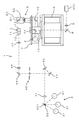
- FIG. 1 is a schematic plan view showing a configuration example of a refractive index measuring apparatus according to an embodiment of the present invention.
- This refractive index measurement device is a V block type refractive index measurement device that measures the refractive index of a sample by irradiating the sample with measurement light via a V block prism 1.
- sample examples include glass, plastic, and liquid.
- the sample is placed in a V-shaped groove 11 formed in the V block prism 1 (FIG. 1 shows the groove 11 viewed from directly above), and the measurement light transmitted through the sample is detected.
- the refractive index of the sample can be measured by detecting with the instrument 2.
- a light source unit 3 for irradiating measurement light in addition to the V block prism 1 and the detector 2 described above, a light source unit 3 for irradiating measurement light, and a first optical system for guiding the measurement light from the light source unit 3 to the V block prism 1 4 and a second optical system 5 for guiding the measurement light transmitted through the V block prism 1 to the detector 2.
- the light source unit 3 is provided with a plurality of light sources 31.
- the light source 31 for example, a helium lamp, a hydrogen lamp, and a mercury lamp are used, and measurement light having different wavelengths such as a helium d line, a hydrogen C line, a hydrogen F line, a mercury e line, a mercury g line, and a mercury h line is used as the light source. Irradiation from the unit 3 is possible. Measurement light from the light source 31 is reflected by the mirror 32 and irradiated from the light source unit 3 in the horizontal direction.
- the mirror 32 is rotatable about a rotation shaft 321 extending in the vertical direction (the front-rear direction in FIG. 1), and the measurement light from the light source 31 corresponding to the rotation position of the mirror 32 is sent to the first optical system 4. Can lead.
- the light source 31 is not limited to the above type.
- the first optical system 4 includes a lens 41, mirrors 42, 43, and 44, an interference filter 45, a slit 46, a collimator lens 47, and the like. Measurement light from the light source unit 3 passes through the lens 41, is sequentially reflected by the mirrors 42 and 43, and then enters the interference filter 45.
- a plurality of interference filters 45 are provided, and only the measurement light (monochromatic light) having a specific wavelength corresponding to the interference filter 45 is inserted by inserting the interference filter 45 selected according to the type of the light source 31 into the optical path. Is transmitted through the interference filter 45 and guided to the mirror 44 side. The measurement light reflected by the mirror 44 passes through the slit 46, is converted into parallel light by the collimator lens 47, and then enters the V block prism 1. The measurement light incident on the V block prism 1 from one end face 12 passes through the sample placed in the V-shaped groove 11, passes through the V block prism 1 again, and passes through the V block prism 1 and the sample. The light is emitted from the other end face 13 at an angle corresponding to the difference in refractive index.
- the second optical system 5 includes mirrors 51 and 52, a telemeter lens 53, a beam splitter 54, and the like.
- the second optical system 5 is fixed to a disc 7 attached to a rotating shaft 61 of the motor 6.
- the mirrors 51 and 52 and the telemeter lens 53 are arranged in parallel to the rotation shaft 61 at a position eccentric with respect to the rotation shaft 61, and the mirror 52 and the beam splitter 54 are perpendicular to the rotation shaft 61.
- Each is fixed to the disc 7 so as to be lined up.
- the mirror 51 is arranged so that the reflection surface is inclined by 45 ° with respect to the incident direction of the measurement light, so that the measurement light reflected by the mirror 51 is converted into the traveling direction by 90 ° and guided to the telemeter lens 53. It is burned.
- the telemeter lens 53 condenses the measurement light from the V block prism 1 and guides it to the mirror 52, and the measurement light reflected by the mirror 52 passes through the beam splitter 54 and is fixed to the disk 7. Is detected.
- the mirror 51 and the telemeter lens 53 are arranged in a line in a direction perpendicular to the incident direction of the measurement light from the V block prism 1, and are integrated into a circle as the telemeter unit 50 at a position eccentric with respect to the rotation shaft 61. It is held on the plate 7. Therefore, by rotating the motor 6 and rotating the disk 7 around the rotation shaft 61, the position of the telemeter unit 50 relative to the V block prism 1 is changed (scanned), and the measurement light from the V block prism 1 is measured. Can be received from different angles and guided to the detector 2.
- the motor 6 is composed of a servo motor with an encoder, for example, and can accurately grasp the rotation angle of the motor 6.
- the measurement light reflected by the beam splitter 54 is reflected by the mirror 8, passes through the lens 9, is guided to the camera 200, and the measurement light transmitted through the sample can be imaged by the camera 200. That is, the measurement light that has passed through the slit 46 passes through the V block prism 1 and the sample and then enters the camera 200.
- the slit 46 may be arranged on the downstream side of the V block prism 1 so that the measurement light transmitted through the V block prism 1 and the sample may pass through the slit 46.
- the beam splitter 54 and the mirror 8 are provided on the rotating shaft 61. When adjusting the position of the V block prism 1, the autocollimation prism 10 is inserted on the optical path between the beam splitter 54 and the mirror 8. It is possible.
- the camera 200 can be constituted by a CCD (Charge Coupled Device) camera, for example.
- the camera 200 is not limited to the configuration provided at the position as described above.
- the measurement light is guided to the camera 200 via a beam splitter that is attached to the disk 7 and provided separately from the beam splitter 54.
- a beam splitter that is attached to the disk 7 and provided separately from the beam splitter 54.
- Such a configuration may be used, or a configuration in which two or more cameras 200 are provided may be used.
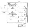
- FIG. 2 is a block diagram illustrating a configuration example of the control unit 100 in the refractive index measurement apparatus of FIG.
- the operation of this refractive index measuring device is controlled by a control unit 100 including, for example, a CPU (Central Processing Unit).
- the control unit 100 executes the program, the control unit 100 performs a data acquisition processing unit 110, a refractive index measurement processing unit 120, a half-value width calculation processing unit 130, an S / N ratio calculation processing unit 140, a determination processing unit 150, and a notification process. It functions as the unit 160 or the like.
- the data acquisition processing unit 110 acquires light intensity distribution data based on an input signal from the camera 200 or the detector 2.
- the data acquisition processing unit 110 includes a first data acquisition processing unit 111 that acquires light intensity distribution data based on an image of measurement light incident on the camera 200 and a detection intensity of measurement light detected by the detector 2. And a second data acquisition processing unit 112 for acquiring light intensity distribution data.
- the first data acquisition processing unit 111 acquires the light intensity distribution data by processing the measurement light image that has passed through the slit 46 and entered the camera 200.
- the image has a straight and long shape corresponding to the slit 46, and the relationship between the position along a specific direction on the image and the luminance (light intensity) at each position is acquired as light intensity distribution data.
- the specific direction is, for example, a direction parallel to or perpendicular to the direction in which the slit 46 extends.
- the second data acquisition processing unit 112 changes the rotation angle of the motor 6 and the detection intensity (light) of the detector 2 at each rotation angle while changing the angle at which the measurement light emitted from the sample is received by rotating the motor 6. Intensity) is acquired as light intensity distribution data.
- the detection signal from the detector 2 includes a noise component. For example, by separating the signal component and the noise component by using a known method such as filtering or frequency analysis, the light intensity consisting only of the signal component is obtained. Distribution data can be acquired.
- the refractive index measurement processing unit 120 measures the refractive index of the sample based on the light intensity distribution data acquired by the second data acquisition processing unit 112. Specifically, the rotation angle corresponding to the highest detection intensity (peak value) is specified from the detection intensities of the detector 2 at each rotation angle of the motor 6, and the rotation angle and the refractive index of the V block prism 1 are specified. Based on the above, the refractive index of the sample is measured.
- the half-value width calculation processing unit (width calculation processing unit) 130 performs processing for calculating the half-value width for the peak of the light intensity distribution data acquired by the data acquisition processing unit 110. Specifically, in the graph of the light intensity distribution data with the vertical axis representing the light intensity, the width of the horizontal axis corresponding to the half value of the peak value of the light intensity distribution data is calculated as the half value width. In the present embodiment, the case where the half-value width is calculated for each peak of the light intensity distribution data acquired by both the first data acquisition processing unit 111 and the second data acquisition processing unit 112 will be described. The half width may be calculated only for the peak of the light intensity distribution data acquired by one of the acquisition processing unit 111 or the second data acquisition processing unit 112. Further, the width corresponding to an arbitrary ratio such as 60% or 40% may be calculated without being limited to the width (half width) where the ratio of the light intensity to the peak value is 50% or more. .
- the S / N ratio calculation processing unit 140 performs processing for calculating the S / N ratio for the peak of the light intensity distribution data acquired by the data acquisition processing unit 110. Specifically, the ratio between the peak value (S value) and the noise component amplitude (N value) in the graph of the light intensity distribution data with the vertical axis representing the light intensity is calculated as the S / N ratio.
- S value peak value
- N value noise component amplitude
- the S / N ratio may be calculated only for the peak of the light intensity distribution data acquired by one of the one data acquisition processing unit 111 or the second data acquisition processing unit 112.
- the determination processing unit 150 uses the refractive index of the sample measured by the refractive index measurement processing unit 120 based on the peak of each light intensity distribution data acquired by the first data acquisition processing unit 111 and the second data acquisition processing unit 112. Judge the quality of the. That is, it is determined whether or not the measured refractive index value of the sample is a highly reliable value.
- the refractive index measurement processing unit 120 measures the half width calculated by the half width calculation processing unit 130 and the S / N ratio calculated by the S / N ratio calculation processing unit 140. The quality of the refractive index of the sample is determined. Such determination of pass / fail may be performed, for example, by comparing the full width at half maximum or the S / N ratio with a threshold value.
- the notification processing unit 160 performs processing for notifying the determination result by the determination processing unit 150.
- the notification processing unit 160 controls the display on the display unit 300 to display the determination result by the determination processing unit 150 on the display unit 300.
- the display unit 300 includes, for example, a liquid crystal display, and may be provided in the refractive index measuring device or may be provided separately from the refractive index measuring device.
- the display unit 300 also displays an image captured by the camera 200, light intensity distribution data acquired by the data acquisition processing unit 110, and the like.
- FIG. 3A is a schematic diagram illustrating an example of an aspect in which an image photographed by the camera 200 is displayed on the display unit 300.
- FIG. 3B is a schematic diagram illustrating an example of an aspect in which the light intensity distribution data acquired by the data acquisition processing unit 110 is displayed on the display unit 300.
- the image photographed by the camera 200 as shown in FIG. 3A and the light intensity distribution data as shown in FIG. 3B may be displayed separately on the display unit 300 or may be displayed on the same screen. Good.
- the image photographed by the camera 200 as shown in FIG. 3A includes the measurement light image 301 that has passed through the slit 46.
- the image 301 has an elongated shape in the direction D1 parallel to the direction in which the slit 46 extends, and normally the width in the direction D2 perpendicular to the direction in which the slit 46 extends is small.
- the image 301 may be blurred and the width in the vertical direction D2 may be increased. In such a case, the measured refractive index of the sample may not be good.
- the light intensity distribution data shown in FIG. 3B is the light intensity distribution data acquired by the second data acquisition processing unit 112, the rotation angle of the motor 6 being the horizontal axis, and the detection intensity (light intensity) of the detector 2 being the vertical axis. And is represented by a graph. This light intensity distribution data may be displayed so as to change in real time as the motor 6 rotates.
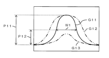
- FIG. 4 is a diagram for explaining an aspect when determining the quality of the measured refractive index of the sample based on the light intensity distribution data shown in FIG. 3B.
- the graph G11 shown in FIG. 4 is a graph in which the rotation angle of the motor 6 is the horizontal axis and the detection intensity (light intensity) of the detector 2 is the vertical axis, and the horizontal value corresponding to half of the peak value P11 is P12.
- the width of the axis is calculated by the half-value width calculation processing unit 130 as the half-value width W1.
- the refractive index of the measured sample is better as the half width W1 is smaller and the peak is steeper.
- the measured refractive index of the sample is, for example, because a sample having a non-uniform refractive index is measured. It can be judged that it is not good.
- a graph G13 in FIG. 4 when the peak value is small, the S / N ratio is small and it can be determined that the measured refractive index of the sample is not good.
- FIG. 5 is a diagram for explaining an aspect when determining the quality of the refractive index of the measured sample based on the image 301 of the camera 200 as shown in FIG. 3A.
- the graph G21 shown in FIG. 5 is a graph in which the horizontal axis indicates the position in the parallel direction D1 with respect to the direction in which the slit 46 extends in the image 301 of the camera 200, and the vertical axis indicates the luminance (light intensity) at each position.
- the width on the horizontal axis corresponding to the half value P22 of the peak value P21 is calculated by the half value width calculation processing unit 130 as the half value width W2.
- FIG. 6 is a diagram for explaining another mode when determining the quality of the measured refractive index of the sample based on the image 301 of the camera 200 as shown in FIG. 3A.
- a graph G31 shown in FIG. 6 is a graph in which the horizontal axis indicates the position in the vertical direction D2 with respect to the direction in which the slit 46 extends in the image 301 of the camera 200, and the vertical axis indicates the luminance (light intensity) at each position.
- the width on the horizontal axis corresponding to the half value P32 of the peak value P31 is calculated by the half value width calculation processing unit 130 as the half value width W3.
- the image 301 is not blurred along the vertical direction D2, and it can be determined that the refractive index of the measured sample is better.
- the graph G32 in FIG. 6 when the half-value width is large and the peak is not steep, the image 301 is blurred and measured along the vertical direction D2 as shown by the alternate long and short dash line in FIG. It can be judged that the refractive index of the sample is not good.
- a graph G33 in FIG. 6 when the peak value is small, the S / N ratio is small and it can be determined that the measured refractive index of the sample is not good.
- the peak of the light intensity distribution data (see FIGS. 5 and 6) acquired based on the image 301 of the measurement light incident on the camera 200 and the measurement detected by the detector 2.
- the quality of the measured refractive index of the sample is determined. In this way, not only the detection intensity of the measurement light detected by the detector 2 but also the image 301 of the measurement light incident on the camera 200 is used to accurately determine the refractive index of the measured sample. Can do.
- the quality of the measured refractive index of the sample can be automatically and easily determined based on the peak of each light intensity distribution data, and the determination result does not vary depending on the operator. Therefore, the quality of the measured refractive index of the sample can be easily and accurately determined.
- the half-value widths W1 to W3 calculated for the peaks of the light intensity distribution data are indicators of whether or not the peaks are steep. Therefore, by using such half-value widths W1 to W3, The quality of the refractive index can be accurately determined. Further, since the S / N ratio calculated for the peak of the light intensity distribution data is an indicator of whether the peak values P11, P21, and P31 are large, the S / N ratio was measured by using such S / N ratio. The quality of the refractive index of the sample can be accurately determined.
- the determination result notified by the notification processing unit 160 may include an alert or warning.
- the present invention is not limited to such a configuration, and for example, a configuration in which the determination result by the determination processing unit 150 is notified using a method other than display such as voice may be used.
- V block type refractive index measuring device to which the present invention is applied is not limited to the configuration shown in FIG. 1 as long as the configuration includes the detector 2, the light source unit 3, the slit 46, and the camera 200. Any other configuration can be employed.
- the arrangement positions of the light source unit 3 and the camera 200 may be interchanged, and various mirrors and lenses can be appropriately added or omitted.
Abstract
Dans la présente invention, une première unité de traitement d'acquisition de données 111 acquiert des données de distribution d'intensité de lumière sur la base d'une image de lumière de mesure qui a pénétré dans une caméra 200. Une deuxième unité de traitement d'acquisition de données 112 acquiert des données de distribution d'intensité de lumière sur la base de l'intensité détectée de la lumière de mesure détectée par un détecteur 2. Une unité de traitement de mesure d'indice de réfraction 120 mesure l'indice de réfraction d'un échantillon sur la base des données de distribution d'intensité de lumière acquises par la deuxième unité de traitement d'acquisition de données 112. Une unité de traitement de détermination 150 détermine si l'indice de réfraction de l'échantillon mesuré par l'unité de traitement de mesure d'indice de réfraction 120 est acceptable sur la base des pics des données de distribution d'intensité de lumière acquises par la première unité de traitement d'acquisition de données 111 et la deuxième unité de traitement d'acquisition de données 112.
Priority Applications (3)
| Application Number | Priority Date | Filing Date | Title |
|---|---|---|---|
| US16/075,793 US10416077B2 (en) | 2016-02-08 | 2016-02-08 | V-block refractometer |
| JP2017566265A JPWO2017138083A1 (ja) | 2016-02-08 | 2016-02-08 | Vブロック方式の屈折率測定装置 |
| PCT/JP2016/053707 WO2017138083A1 (fr) | 2016-02-08 | 2016-02-08 | Réfractomètre à bloc v |
Applications Claiming Priority (1)
| Application Number | Priority Date | Filing Date | Title |
|---|---|---|---|
| PCT/JP2016/053707 WO2017138083A1 (fr) | 2016-02-08 | 2016-02-08 | Réfractomètre à bloc v |
Publications (1)
| Publication Number | Publication Date |
|---|---|
| WO2017138083A1 true WO2017138083A1 (fr) | 2017-08-17 |
Family
ID=59563028
Family Applications (1)
| Application Number | Title | Priority Date | Filing Date |
|---|---|---|---|
| PCT/JP2016/053707 WO2017138083A1 (fr) | 2016-02-08 | 2016-02-08 | Réfractomètre à bloc v |
Country Status (3)
| Country | Link |
|---|---|
| US (1) | US10416077B2 (fr) |
| JP (1) | JPWO2017138083A1 (fr) |
| WO (1) | WO2017138083A1 (fr) |
Cited By (2)
| Publication number | Priority date | Publication date | Assignee | Title |
|---|---|---|---|---|
| CN109557047A (zh) * | 2017-09-26 | 2019-04-02 | 株式会社岛津制作所 | 折射率测定装置及折射率测定方法 |
| JP2019060714A (ja) * | 2017-09-26 | 2019-04-18 | 株式会社島津製作所 | 液体試料測定用アタッチメント、屈折率測定装置及び屈折率測定方法 |
Families Citing this family (1)
| Publication number | Priority date | Publication date | Assignee | Title |
|---|---|---|---|---|
| DE102016203891B4 (de) * | 2016-03-09 | 2019-07-11 | Numares Ag | Verfahren zur Durchführung einer NMR-Messung und NMR-Spektrometer-Anordnung |
Citations (5)
| Publication number | Priority date | Publication date | Assignee | Title |
|---|---|---|---|---|
| JPH03249508A (ja) * | 1990-02-28 | 1991-11-07 | Mitsubishi Heavy Ind Ltd | 三次元形状認識装置 |
| JPH07128228A (ja) * | 1993-10-29 | 1995-05-19 | Shimadzu Corp | 原子吸光分光光度計 |
| JP2006098208A (ja) * | 2004-09-29 | 2006-04-13 | Fuji Photo Film Co Ltd | 全反射減衰を利用した測定装置 |
| WO2014207809A1 (fr) * | 2013-06-24 | 2014-12-31 | 株式会社島津製作所 | Appareil de mesure d'indices de réfraction |
| WO2015001650A1 (fr) * | 2013-07-04 | 2015-01-08 | 株式会社島津製作所 | Réfractomètre à bloc en v et dispositif et procédé de calcul d'un indice de réfraction l'utilisant |
Family Cites Families (4)
| Publication number | Priority date | Publication date | Assignee | Title |
|---|---|---|---|---|
| JP2006170775A (ja) * | 2004-12-15 | 2006-06-29 | Canon Inc | 屈折率測定方法およびその測定装置 |
| JP2008107320A (ja) * | 2006-09-29 | 2008-05-08 | Fujifilm Corp | 検出装置、検出方法、及び光透過性部材 |
| JP5306269B2 (ja) * | 2009-06-25 | 2013-10-02 | キヤノン株式会社 | 光干渉断層法を用いる撮像装置及び撮像方法 |
| DE102012223128B4 (de) * | 2012-12-13 | 2022-09-01 | Carl Zeiss Microscopy Gmbh | Autofokusverfahren für Mikroskop und Mikroskop mit Autofokuseinrichtung |
-
2016
- 2016-02-08 WO PCT/JP2016/053707 patent/WO2017138083A1/fr active Application Filing
- 2016-02-08 JP JP2017566265A patent/JPWO2017138083A1/ja active Pending
- 2016-02-08 US US16/075,793 patent/US10416077B2/en active Active
Patent Citations (5)
| Publication number | Priority date | Publication date | Assignee | Title |
|---|---|---|---|---|
| JPH03249508A (ja) * | 1990-02-28 | 1991-11-07 | Mitsubishi Heavy Ind Ltd | 三次元形状認識装置 |
| JPH07128228A (ja) * | 1993-10-29 | 1995-05-19 | Shimadzu Corp | 原子吸光分光光度計 |
| JP2006098208A (ja) * | 2004-09-29 | 2006-04-13 | Fuji Photo Film Co Ltd | 全反射減衰を利用した測定装置 |
| WO2014207809A1 (fr) * | 2013-06-24 | 2014-12-31 | 株式会社島津製作所 | Appareil de mesure d'indices de réfraction |
| WO2015001650A1 (fr) * | 2013-07-04 | 2015-01-08 | 株式会社島津製作所 | Réfractomètre à bloc en v et dispositif et procédé de calcul d'un indice de réfraction l'utilisant |
Cited By (3)
| Publication number | Priority date | Publication date | Assignee | Title |
|---|---|---|---|---|
| CN109557047A (zh) * | 2017-09-26 | 2019-04-02 | 株式会社岛津制作所 | 折射率测定装置及折射率测定方法 |
| JP2019060714A (ja) * | 2017-09-26 | 2019-04-18 | 株式会社島津製作所 | 液体試料測定用アタッチメント、屈折率測定装置及び屈折率測定方法 |
| CN109557047B (zh) * | 2017-09-26 | 2022-01-14 | 株式会社岛津制作所 | 折射率测定装置及折射率测定方法 |
Also Published As
| Publication number | Publication date |
|---|---|
| JPWO2017138083A1 (ja) | 2018-08-16 |
| US10416077B2 (en) | 2019-09-17 |
| US20190041327A1 (en) | 2019-02-07 |
Similar Documents
| Publication | Publication Date | Title |
|---|---|---|
| KR100917912B1 (ko) | 단일 편광자 초점 타원계측기 | |
| US10976217B2 (en) | System and method for inspecting optical power and thickness of ophthalmic lenses immersed in a solution | |
| JP2013213820A (ja) | 試料内の不均質性を検知するための光学装置、特に偏光計 | |
| JPH03267745A (ja) | 表面性状検出方法 | |
| WO2007052347A1 (fr) | Dispositif de mesure de lentille | |
| JP2008175565A (ja) | 光透過性部材の欠陥検出装置及び方法 | |
| WO2017138083A1 (fr) | Réfractomètre à bloc v | |
| KR101126150B1 (ko) | 렌즈미터 | |
| JP6217748B2 (ja) | 屈折率測定装置 | |
| JP6769605B2 (ja) | レンズメータ | |
| CN111220088B (zh) | 测量系统和方法 | |
| EP1896792B1 (fr) | Procede et systeme pour mesurer la courbure d'une surface optique | |
| CN109557047B (zh) | 折射率测定装置及折射率测定方法 | |
| JP5983881B2 (ja) | Vブロック方式の屈折率測定装置並びにこれに用いられる屈折率算出装置及び屈折率算出方法 | |
| JP2008256504A (ja) | 形状測定装置 | |
| JP7357389B2 (ja) | 偏光レンズのレンズ偏光軸の配向を特定する装置及び方法 | |
| JP2009222485A (ja) | 光学式センサ装置およびその設置状態確認方法 | |
| JP2554949B2 (ja) | 眼鏡レンズ測定装置 | |
| JPS63182547A (ja) | 粒子解析装置 | |
| KR900005642B1 (ko) | 광파이버 구조 및 외경측정의 장치 및 방법 | |
| RU2282170C2 (ru) | Устройство для контроля качества объективов | |
| JP2015004601A (ja) | 偏芯測定装置、偏芯測定方法およびレンズの製造方法 | |
| JP2008256425A (ja) | 形状測定装置 | |
| JPS6166139A (ja) | フイルタ膜検査装置 | |
| JP2016109593A (ja) | 屈折率計測方法、屈折率計測装置、及び光学素子の製造方法 |
Legal Events
| Date | Code | Title | Description |
|---|---|---|---|
| 121 | Ep: the epo has been informed by wipo that ep was designated in this application |
Ref document number: 16889785 Country of ref document: EP Kind code of ref document: A1 |
|
| ENP | Entry into the national phase |
Ref document number: 2017566265 Country of ref document: JP Kind code of ref document: A |
|
| NENP | Non-entry into the national phase |
Ref country code: DE |
|
| 122 | Ep: pct application non-entry in european phase |
Ref document number: 16889785 Country of ref document: EP Kind code of ref document: A1 |