WO2017135074A1 - 溶融金属用の添加材投入方法、および溶融金属用の添加材投入装置 - Google Patents
溶融金属用の添加材投入方法、および溶融金属用の添加材投入装置 Download PDFInfo
- Publication number
- WO2017135074A1 WO2017135074A1 PCT/JP2017/001978 JP2017001978W WO2017135074A1 WO 2017135074 A1 WO2017135074 A1 WO 2017135074A1 JP 2017001978 W JP2017001978 W JP 2017001978W WO 2017135074 A1 WO2017135074 A1 WO 2017135074A1
- Authority
- WO
- WIPO (PCT)
- Prior art keywords
- additive
- nozzle
- container
- heat insulating
- insulating material
- Prior art date
- Legal status (The legal status is an assumption and is not a legal conclusion. Google has not performed a legal analysis and makes no representation as to the accuracy of the status listed.)
- Ceased
Links
Images

Classifications
-
- B—PERFORMING OPERATIONS; TRANSPORTING
- B22—CASTING; POWDER METALLURGY
- B22D—CASTING OF METALS; CASTING OF OTHER SUBSTANCES BY THE SAME PROCESSES OR DEVICES
- B22D1/00—Treatment of fused masses in the ladle or the supply runners before casting
- B22D1/002—Treatment with gases
- B22D1/005—Injection assemblies therefor
-
- B—PERFORMING OPERATIONS; TRANSPORTING
- B22—CASTING; POWDER METALLURGY
- B22D—CASTING OF METALS; CASTING OF OTHER SUBSTANCES BY THE SAME PROCESSES OR DEVICES
- B22D1/00—Treatment of fused masses in the ladle or the supply runners before casting
-
- B—PERFORMING OPERATIONS; TRANSPORTING
- B22—CASTING; POWDER METALLURGY
- B22D—CASTING OF METALS; CASTING OF OTHER SUBSTANCES BY THE SAME PROCESSES OR DEVICES
- B22D11/00—Continuous casting of metals, i.e. casting in indefinite lengths
- B22D11/10—Supplying or treating molten metal
- B22D11/108—Feeding additives, powders, or the like
-
- B—PERFORMING OPERATIONS; TRANSPORTING
- B22—CASTING; POWDER METALLURGY
- B22D—CASTING OF METALS; CASTING OF OTHER SUBSTANCES BY THE SAME PROCESSES OR DEVICES
- B22D27/00—Treating the metal in the mould while it is molten or ductile ; Pressure or vacuum casting
- B22D27/003—Treating the metal in the mould while it is molten or ductile ; Pressure or vacuum casting by using inert gases
-
- B—PERFORMING OPERATIONS; TRANSPORTING
- B22—CASTING; POWDER METALLURGY
- B22D—CASTING OF METALS; CASTING OF OTHER SUBSTANCES BY THE SAME PROCESSES OR DEVICES
- B22D27/00—Treating the metal in the mould while it is molten or ductile ; Pressure or vacuum casting
- B22D27/04—Influencing the temperature of the metal, e.g. by heating or cooling the mould
- B22D27/06—Heating the top discard of ingots
Definitions
- the present invention relates to an additive charging method and an additive charging apparatus for charging an additive such as a heat insulating material into a container in which molten metal such as molten steel is accommodated in a metal production process, for example, a steelmaking process, and more particularly
- the present invention relates to an additive charging method and an additive charging apparatus for charging an additive into a container using a nozzle.
- the hot metal produced in the blast furnace is appropriately pretreated and then decarburized and heat-treated using a converter to become molten steel at about 1600 ° C.
- This molten steel is subjected to component adjustment and degassing treatment using secondary refining equipment.
- Molten steel that has undergone such a steelmaking process is solidified using a continuous casting machine, and becomes a slab of steel such as slab, bloom, billet and the like.
- the molten steel that has undergone the processing step using the converter (hereinafter referred to as the “converter step”) is conveyed in the order of the secondary refining equipment and the continuous casting machine in a state of being accommodated in a container such as a ladle. Processed.
- the molten steel supplied to the continuous casting machine needs to have an appropriate temperature higher than the solidification temperature.
- the temperature of the molten steel in a container falls by heat dissipation.
- the operation time for secondary refining increases. Furthermore, by performing the temperature raising process, an oxide originating from the oxidizable element is generated, and the amount of the oxide in the molten steel is increased. In this case, the nozzle for supplying the molten steel to the continuous casting machine is likely to be clogged and the productivity is lowered, and the quality of the slab obtained by continuously casting such molten steel is lowered. Therefore, it is preferable not to carry out the temperature raising process during the secondary refining.
- a heat insulating material (a heat insulating material for molten steel) into a container in which the molten steel is accommodated.
- a heat insulating material has the form of the aggregate
- the heat insulating material is required to have the following characteristics. (1) The density is smaller than that of molten steel. (2) Do not react adversely affecting the molten steel. (3) By covering the surface of the molten steel, heat radiation from the molten steel to the atmosphere can be suppressed.
- the heat insulating material is preferably dispersed without agglomerating on the molten steel surface.
- materials that can be used as a heat insulating material include vermiculite (heat-treated garnet, bituminous meteorite, etc.), grilled rice (baked rice husk), and the like.
- the heat insulating material is supplied to the entire surface of the molten steel.
- the heat insulating material charging method there is a method in which all the heat insulating materials to be charged are divided into a plurality of charging units and charged so that each amount is about 10 kg or less.
- the heat insulating material is packed in a sachet for each charging unit, and is charged while being appropriately dispersed manually in a container in which molten steel is accommodated.
- the molten steel transferred from the converter to the container has a high temperature of 1600 ° C. or higher, there is a restriction that a person can work close to the vicinity of the molten steel.
- Patent Document 1 discloses a method in which a hopper containing a heat insulating material is installed above a container and the heat insulating material is dropped by the action of gravity. A plurality of valve pieces are provided at the bottom of the hopper, and by opening each valve piece, the heat insulating material in the hopper can be discharged and put into the container. In this manner, the heat insulating material is supplied to the entire surface of the molten steel by supplying the heat insulating material from a plurality of parts at the bottom of the hopper.
- a heat insulating material filled in a flexible container bag is disposed in a box-shaped jig whose bottom is configured in a lattice shape, and the heat insulating material is broken by gravity by breaking the flexible container bag with the heat of molten steel.
- a method of dropping by the action of is disclosed. In this method, when the heat insulating material passes through the lattice, the duration of the heat insulating material falling becomes longer. For this reason, during the fall of the heat insulating material, the heat insulating material can be supplied to the entire surface of the molten steel by moving the box-shaped jig within the horizontal plane by the crane.
- Patent Document 3 discloses a method of introducing a heat insulating material into a tundish containing molten steel using a carrier gas.
- a nozzle outlet is disposed between the tundish lid and the molten steel surface, and the heat insulating material is sprayed onto the molten steel surface together with the carrier gas from the outlet. According to this method, the coverage of the heat insulating material on the molten steel surface is improved.
- Patent Document 3 it is possible to avoid an excessive input of the heat insulating material and to optimize the amount of the heat insulating material input, which is effective for cost improvement.
- the heat insulating material can be supplied to the molten steel surface uniformly to some extent.
- the heat insulating material falls by the action of gravity and is supplied to the surface of the molten steel.
- the number of divisions of the heat insulating material is limited.
- the exposed part from a heat insulating material increases in the molten steel surface, and a heat retention effect may become inadequate.
- the exposure of the molten steel surface is to be reduced in order to ensure a sufficient heat retaining effect, there is a problem that the amount of the heat retaining material is excessive and the economy is inferior.
- Patent Document 3 since the heat insulating material is sprayed onto the surface of the molten steel together with the carrier gas, the heat insulating effect and the amount of the heat insulating material used can be optimized by being uniformly supplied to the molten steel surface.
- Patent Document 3 describes a case where this method is applied to a tundish provided with a lid on the upper portion, and a method of applying similar equipment in a container not provided with a lid, There is no specific description.
- this method is applied to a container that is not provided with a lid, the nozzle outlet of the nozzle faces in the horizontal direction, so that the heat insulating material is easily carried to the surroundings by being transported by the rising airflow. As a result, a sufficient heat retention effect cannot be obtained, or it is necessary to increase the amount of the heat retaining material used to ensure the heat retention effect, resulting in a deterioration in economic efficiency.
- slag modifier or slag solidifying material may be supplied to the surface of the molten steel. Also in this case, unless the slag modifying material or the slag solidifying material is uniformly applied to the surface of the molten steel, the effect of the slag reforming or the slag solidifying cannot be sufficiently obtained. Moreover, when the slag modifier or slag solidifying material is scattered, the environment and economy are deteriorated. Furthermore, the same problem may occur when an additive is added to molten metal other than molten steel, for example, hot metal.
- the present invention supplies the additive uniformly to the surface of the molten metal accommodated in the container regardless of whether or not the container is provided with a lid, and provides a sufficient additive effect of the additive. It is an object of the present invention to provide an additive feeding method and an additive feeding apparatus that can achieve both reduction in the amount of additive used.
- the gist of the present invention is the following additive feeding method (1) and the following additive feeding device (2).
- a method of introducing an additive into a container containing molten metal A nozzle arrangement step of arranging a nozzle above the molten metal contained in the container;
- the additive material is transported to the nozzle by a carrier gas, and the additive material is ejected from the nozzle outlet, and Including In the nozzle, the additive material charging method, wherein the area of the jet outlet is larger than the area of the inlet.
- the additive is supplied uniformly to the surface of the molten metal contained in the container regardless of whether the container is provided with a lid. It is possible to achieve both a sufficient additive effect and a reduction in the amount of additive used.
- an additive effect of the additive for example, when the additive is a heat insulating material, a sufficient heat insulating effect is obtained.
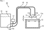
- FIG. 1 is a cross-sectional view of a heat insulating material charging device according to an embodiment of the present invention.
- FIG. 2 is a cross-sectional view showing a configuration in the vicinity of a connection portion between the transfer pipe and the carrier gas introduction device.
- the present inventors conducted various experiments on a method for uniformly supplying a heat insulating material to the surface of molten steel in a container not provided with a lid.
- a method for uniformly supplying a heat insulating material to the surface of molten steel in a container not provided with a lid First, with respect to the surface of the molten steel in a container not provided with a lid, one nozzle having a jet port formed at the lower end is disposed above, and the heat insulating material is transferred from the nozzle jet port to the molten steel surface by a carrier gas.
- the test which sprays on was conducted.
- the diameter of the opening of the container was set to 3.0 m or more. At this time, the nozzle outlet was directed vertically downward.
- the result is as follows. That is, when the amount of the heat insulating material used is increased to such an extent that the heat insulating material can be uniformly supplied to the surface of the molten steel, the amount of the heat insulating material scattered by the ascending airflow from the surface of the molten steel increases, and the environment around the equipment is deteriorated.
- the heat insulating material when the nozzle height was 1.2 m or less, the heat insulating material was not substantially scattered. However, in this case, the heat insulating material could not be uniformly supplied to the molten steel surface, and the amount of the heat insulating material deposited on the molten steel surface was uneven. In particular, when the nozzle height was less than 0.4 m, the amount of heat insulating material deposited on the surface of the molten steel was remarkable.
- the present inventors also examined changing the number and shape of nozzle nozzles.
- a heat insulating material is uniformly supplied to the surface of the molten steel in the container having no opening and the diameter of the opening is 3.0 m or more, and a sufficient heat insulating effect and a reduction in the amount of the heat insulating material used. As long as a single nozzle is used, it has been expected to be difficult to achieve both.
- the present inventors conducted a test in which two nozzles were provided above the molten steel accommodated in the container and a heat insulating material was put into the container. As a result, it was confirmed that the heat insulating material was uniformly dispersed on the surface of the molten steel and the scattering of the heat insulating material due to the rising airflow over the molten steel was reduced. In particular, when the nozzle height is set to 0.4 m or more and 1.2 m or less, the uniformity of the heat insulating material supplied to the molten steel surface is high, and the scattering of the heat insulating material due to the rising air current on the molten steel did not substantially occur. .
- the present inventors have examined the appropriate amount of the heat insulating material, and when the average thickness of the heat insulating material deposited on the molten steel surface is 5 mm or more and 25 mm or less, the balance between the heat insulating effect and the amount of the heat insulating material used. However, it confirmed that it became further favorable. Since the particle size of the heat insulating material is generally about 5 mm, the entire molten steel surface cannot be covered when the average thickness is less than 5 mm. When the average thickness exceeds 25 mm, the effect of keeping the molten steel warm with respect to the increase in the average thickness is saturated and becomes almost constant, and the amount of the heat insulating material used is excessive. The present invention has been completed based on the above findings.
- the additive charging method of the present invention is a method of charging an additive into a container containing molten metal.
- This method includes a nozzle arrangement step of arranging a nozzle above the molten metal accommodated in a container, and an additive injection step of conveying the additive to the nozzle by a carrier gas and ejecting the additive from the nozzle outlet. Including. In the nozzle, the area of the jet outlet is larger than the area of the inlet.
- the diameter of the opening of the container may be 3.0 m or more.
- the distance in the height direction from the upper end of the container to the jet outlet is preferably set to 0.4 m or more and 1.2 m or less.
- the additive may be a heat insulating material. In this case, it is preferable to deposit the additive with an average thickness of 5 mm or more and 25 mm or less on the surface of the molten metal in the additive jetting step.
- the ratio of the area of the jet outlet to the area of the inlet is preferably 2 or more.
- the molten metal may be molten steel.
- the nozzle arrangement step may include a step of arranging a plurality of nozzles above the molten metal accommodated in the container.
- the additive feeding device of the present invention is a device for feeding an additive into a container containing molten metal.
- This apparatus includes a container, a nozzle, an additive transport pipe, and a carrier gas introduction device.
- the container contains the additive material.
- a nozzle is arrange
- the additive material transport pipe connects the nozzle and the container.
- the carrier gas introduction device supplies a carrier gas to the additive transport pipe, and transports the additive contained in the container to the nozzle through the additive transport pipe with the carrier gas. In the nozzle, the area of the jet outlet is larger than the area of the inlet.
- the ratio of the area of the jet outlet to the area of the inlet is preferably 2 or more.
- the additive may be a heat insulating material.
- the molten metal may be molten steel.
- This additive charging device may include a plurality of nozzles. In this case, the additive transport pipe connects each of the plurality of nozzles to the container, and the carrier gas introduction device transfers the additive contained in the container to each of the plurality of nozzles via the additive transport pipe. It may be transported.
- FIG. 1 is a cross-sectional view showing a configuration of a heat insulating material charging device according to an embodiment of the present invention.
- the heat insulating material charging device 20 includes a container 15 in which the heat insulating material 14 is accommodated, and a plurality (two in this embodiment) of nozzles 11 disposed above the molten steel 13 accommodated in the container 12. .
- the container 12 is used for housing and transporting the molten steel 13.
- the container 12 is not provided with a lid, and the upper part is opened.
- the spout 11a formed in each nozzle 11 is located at the lower end of the nozzle 11 and is directed downward.
- the plurality of nozzles 11 are spaced apart from each other and arranged in the horizontal direction. In the plan view, it is preferable that the plurality of nozzles 11 are evenly arranged with respect to the surface of the molten steel 13 accommodated in the container 12.
- Each nozzle 11 is connected to a container 15 via a transfer pipe 16.
- a heat insulating material discharge port 15 a is formed in the lower part of the side wall of the container 15.
- the conveyance pipe 16 is connected to the heat insulating material discharge port 15a.
- a carrier gas introduction device 17 is connected in the vicinity of the heat insulating material discharge port 15a.
- the carrier gas introduction device 17 introduces a carrier gas for conveying the heat insulating material 14 into the conveyance pipe 16.
- FIG. 2 is a cross-sectional view showing a configuration in the vicinity of a connection portion between the transfer pipe and the carrier gas introduction device.
- the carrier gas introduction device 17 includes a carrier gas storage part (not shown) in which the carrier gas is stored, and a carrier gas introduction pipe 21 that introduces the carrier gas stored in the carrier gas storage part into the transport pipe 16. Yes.
- the carrier gas it is preferable to use an inert gas such as argon gas or nitrogen gas. This is because the inert gas is less likely to react with molten steel (including pickup into molten steel).
- first portion 16 a in the transport pipe 16, a portion (hereinafter referred to as “first portion”) 16 a in the vicinity of a connection portion with the heat insulating material discharge port 15 a is inclined downward in a direction away from the container 15 and functions as a chute.
- second portion 16b adjacent to the first portion 16a is substantially horizontal.
- the carrier gas introduction pipe 21 is connected to the second portion 16 b of the transfer pipe 16. In the vicinity of the connection portion, the carrier gas introduction pipe 21 and the transfer pipe 16 (second portion 16b) closer to the container 15 than the connection portion form an acute angle.
- Part of the heat insulating material 14 accommodated in the container 15 flows into the first portion 16a of the transfer pipe 16 due to the action of gravity, and further flows into the portion adjacent to the first portion 16a in the second portion 16b. .
- the carrier gas introduction device 17 when the carrier gas introduction device 17 is activated and the carrier gas is introduced into the second portion 16b of the transport pipe 16, the carrier gas flows mainly through the transport pipe 16 toward the nozzle 11 side.
- the direction of the main flow of the carrier gas is indicated by broken-line arrows. This is because a large amount of heat insulating material 14 is present in the container 15 side portion of the transport pipe 16 and the pressure loss is large, and the carrier gas introduction pipe 21 is connected to the transport pipe 16 at the above-mentioned angle. It depends on being.
- the portion on the container 15 side from the connection portion between the transfer pipe 16 and the carrier gas introduction pipe 21 becomes a negative pressure, whereby the heat insulating material 14 is connected to the connection portion. After being drawn to the vicinity, it is transported by a carrier gas.
- FIG. 2 the main conveyance direction of a heat insulating material is shown by the white arrow.
- the kind of the heat insulating material 14 accommodated in the container 15 is not particularly limited, for example, vermiculite can be used.
- the diameter of the particles constituting the heat insulating material 14 is preferably 3 to 10 mm, and can be, for example, about 5 mm.
- the diameter of the particles is less than 3 mm, the amount of the heat insulating material 14 scattered by the rising airflow generated above the molten steel 13 cannot be ignored.
- the diameter of the particles exceeds 10 mm, it becomes difficult to smoothly convey the heat insulating material 14 by the carrier gas.
- a mass meter (not shown) is provided under the container 15.
- the total mass of the container 15 and the heat insulating material 14 accommodated in the container 15 can be measured by the mass meter.
- the amount of the heat insulating material 14 charged into the container 12 per unit time can be calculated from the change with time of the mass measured by this mass meter.
- the heat insulating material charging device 20 may include a plurality of containers 15. In this case, one or a plurality of nozzles 11 is provided for each container 15, and each nozzle 11 is connected to the container 15 via a transfer pipe 16 to which a carrier gas introduction device 17 is connected. be able to.
- the area of the ejection port 11 a of the carrier gas and the heat insulating material 14 is larger than the area of the introduction port 11 b (connection portion with the transfer pipe 16) of the carrier gas and the heat insulating material 14.
- the “area” is an opening area when viewed along the central axis of the nozzle 11.
- the carrier gas is supplied from the transfer pipe 16 to the nozzle 11 at a volume velocity of V (m 3 / min).
- the area of the introduction port 11 b is S1 (m 2 )
- the area of the ejection port 11 a is S2 (m 2 ).
- the linear velocity V1 of the carrier gas at the introduction port 11b is V / S1 (m / min)
- the linear velocity V2 of the carrier gas at the discharge port 11a is V / S2 (m / min). min). Since S1 ⁇ S2, V1> V2. That is, the linear velocity of the carrier gas decreases at the ejection port 11a as compared to the introduction port 11b.
- the linear velocity of the carrier gas in the transport pipe 16 needs to be high to some extent.
- the carrier gas is jetted onto the surface of the molten steel 13 in the container 12 together with the heat insulating material 14 with such a large linear velocity, the amount of the heat insulating material 14 scattered outside the container 12 increases.
- the linear velocity of the carrier gas and the heat insulating material 14 is reduced, and such scattering is suppressed. be able to.
- the ratio S2 / S1 of the area S2 of the ejection port 11a to the area S1 of the introduction port 11b is preferably 2 or more, and more preferably 3 or more.
- the area of the nozzle 11 increases continuously from the inlet 11b to the outlet 11a. That is, it is preferable that the inner surface of the nozzle 11 has a shape that expands downward, for example, the shape of a side surface of a cone or a truncated cone. In this case, the cross-sectional shape of the inner surface of the nozzle 11 is a circle.
- the spreading angle of the inner surface of the nozzle 11 is preferably 60 to 90 °. Thereby, it becomes easy to supply the heat insulating material 14 uniformly on the surface of the molten steel 13, and it becomes easy to prevent the heat insulating material 14 from being scattered by the rising airflow generated above the molten steel 13.
- the heat insulating material 14 When the spreading angle of the inner surface of the nozzle 11 is less than 60 °, the heat insulating material 14 is concentrated and ejected in the vicinity of the central axis of the nozzle 11, so that the heat insulating material 14 is uniformly supplied onto the surface of the molten steel 13. Can not.
- the spread angle of the inner surface of the nozzle 11 exceeds 90 °, the heat insulating material 14 spreads from the jet outlet 11a and is ejected, so that the downward velocity component of the heat insulating material 14 becomes small and is carried by the rising air current. The amount of heat insulating material that scatters increases.
- the number of transfer pipes 16 and carrier gas introduction devices 17 is the same as the number of nozzles 11, and a different carrier gas introduction device 17 and transfer pipe 16 are provided for each of the plurality of nozzles 11. Is provided. Without adopting such a configuration, the number of the transfer pipe 16 and the carrier gas introduction device 17 may be smaller than the number of the nozzles 11. In this case, it is possible to provide the corresponding carrier gas introduction device 17 in any nozzle 11 by branching the transfer pipe 16.
- the following problems may occur. That is, when troubles such as clogging of the heat insulating material 14 occur in the portion before the branching (portion on the carrier gas introduction device 17 side of the branching point) in the transport pipe 16, any of the nozzles 11 connected to the transport pipe 16 is connected. The heat insulating material 14 cannot be conveyed. Further, in the transport pipe 16, the heat insulating material 14 transported through the part before branching is not evenly distributed to the part after branching (part on the nozzle 11 side from the branching point), and the transport amount of the heat insulating material is biased. There is.
- the shape of the opening of the container 12 is, for example, a circle, and the diameter is, for example, 3.0 m or more.
- the shape of the opening of the container 12 is circular, the container 12 has, for example, a bottomed cylindrical shape.
- the shape of the opening of the container 12 may not be circular, and may be, for example, a polygon (for example, a rectangle), an ellipse, or an indefinite shape.
- the diameter of a circle having the same area as the opening of the container 12 is, for example, 3.0 m or more.
- the inner surface of the nozzle 11 may have a shape that matches the shape of the opening of the container 12. For example, when the shape of the opening of the container 12 is rectangular, the shape of the cross section of the inner surface of the nozzle 11 can also be rectangular. Thereby, the heat insulating material 14 can be efficiently and uniformly supplied to the surface of the molten steel 13.
- the inner surface of the nozzle 11 may not have a shape that matches the shape of the opening of the container 12.
- the diameter of the opening is less than 3.0 m, it is easy to supply the heat insulating material 14 uniformly to the surface of the molten steel 13 even if the heat insulating material 14 is introduced by one nozzle 11.
- the upper limit of the diameter of the opening of the container 12 is not particularly limited.
- the distance H in the height direction from the upper end of the container 12 to the nozzle 11a (lower end of the nozzle 11) is referred to as “nozzle height”.
- the nozzle height H is preferably 0.4 m or more and 1.2 m or less.
- the number and arrangement of the nozzles 11 are appropriately set so that the heat insulating material 14 can be uniformly supplied onto the surface of the molten steel 13 depending on the size and shape of the container 12.
- the container 12 shall be the ladle into which the molten steel after the blowing in a converter was complete
- the container 12 in this invention is not limited to this.
- the ladle is moved below the plurality of nozzles 11 provided in the heat insulating material feeding device 20 by the ladle transport carriage. Thereby, the some nozzle 11 is arrange
- the nozzle height H is preferably 0.4 m or more and 1.2 m or less.
- the carrier gas introduction device 17 is activated to introduce the carrier gas into the transfer pipe 16. Thereby, the heat insulating material 14 is conveyed in the conveyance piping 16.
- the carrier gas introduction device 17 may be activated after the ladle transport cart is stopped, or may be activated when the ladle transport cart is moving.
- the heat insulating material 14 conveyed through the conveying pipe 16 is ejected together with the carrier gas from the ejection port 11a at the lower end of the nozzle 11 and is put into the ladle.
- the sprayed heat insulating material 14 is uniformly supplied to the surface of the molten steel 13 accommodated in the ladle.
- the nozzle height H is not less than 0.4 m and not more than 1.2 m, the uniformity of the heat insulating material 14 supplied to the surface of the molten steel 13 becomes high.
- the inner surface of the nozzle 11 has a shape that expands downward, the uniformity of the heat insulating material 14 supplied to the surface of the molten steel 13 is further increased.
- the carrier gas introduction device 17 is stopped, and the input of the heat insulating material 14 is ended.
- the charging time of the heat insulating material 14 varies depending on the charging amount, but is about 10 to 30 seconds, for example. Thereafter, the ladle is transported to the place where the next process, for example, the secondary refining process is performed.
- the surface of the molten steel 13 and the heat insulating material 14 covering the surface of the molten steel 13 can be identified visually without using a special instrument. For this reason, the ratio (%) (coverage) of the area covered with the heat insulating material 14 to the entire surface of the molten steel 13 can be estimated by appropriately observing the inside of the ladle.
- the molten steel 13 is calculated based on the following formula based on the input amount (mass) of the heat insulating material 14 and the coverage.
- the average thickness of the heat insulating material 10 deposited on the surface of the film can be obtained.
- [Average thickness] (mm) [input amount of heat insulating material] (kg) / [bulk density of heat insulating material deposition layer] (kg / m 3 ) / [total surface area of molten steel] (m 2 ) ⁇ [covering ratio ] (%) ⁇ 10
- the heat insulating material 14 it is preferable to introduce the heat insulating material 14 so that the average thickness of the heat insulating material deposition layer is 5 mm or more and 25 mm or less. In this case, the balance between the heat retaining effect of the heat retaining material 14 and the amount of the heat retaining material 14 used is good. That is, a sufficient heat retaining effect can be obtained, and excessive use of the heat retaining material 14 can be avoided.
- the present invention is not limited to the above-described embodiment, and various modifications can be made without changing the gist of the invention.
- the container 12 is not provided with a lid (cover), but the present invention can also be applied to the container 12 provided with a lid.
- the nozzle 11 is arranged so that the ejection port 11a of the nozzle 11 is located between the surface of the molten steel 13 and the lid.
- the additive material may be, for example, a slag modifying material or a slag solidifying material in addition to the heat insulating material.
- the molten metal may be, for example, hot metal or a molten metal other than iron.
- the number of nozzles 11 may be three or more, and may be one when the opening of the container is sufficiently small.
- the test which throws a heat insulating material into a container on different conditions was done, and the temperature fall rate of the molten steel in each case was measured.
- 350 to 360 tons of undeoxidized molten steel treated in an upper-bottom blowing converter with a capacity of 350 tons was put into a ladle as a container.
- the temperature of the molten steel after steelmaking was 1590 to 1610 ° C.
- iron alloy containing C, Si, Mn, Al and the like was not charged, and quick lime alone was charged at 1.0 to 1.5 kg / t.
- the shape of the opening of the ladle was circular, and its diameter was 4.7 m. Therefore, the surface area of the molten steel accommodated in the ladle was 17.3 m 2 .
- the ladle was moved about 10 m away from the converter, and a temperature measuring probe for molten steel was inserted from above into the molten steel in the ladle, and the temperature of the molten steel was measured.
- the ladle was moved using a ladle transport cart (the same applies when the ladle was moved in the following explanation). Thereafter, the ladle was further moved about 7 m away from the converter, and a heat insulating material was put into the ladle. For comparison, a test in which no heat insulating material was added was also conducted.
- the heat insulating material was charged by a heat insulating material charging device having the configuration shown in FIG.
- the nozzle was connected to the container by a transfer pipe of about 20 m.
- the container contained a papermaking waste heat insulating material whose particle size was adjusted to 5 mm or more and 10 mm or less.
- the bulk density of this heat insulating material was 0.5 t / m 3 , and it was predicted that the bulk density was the same when deposited on the surface of the molten steel.
- a steel pipe having an inner diameter of 105.3 mm was used as the transfer pipe.
- the nozzle side end of the transport pipe is configured to be separable and can be replaced with one having a different length. The nozzle height was adjusted by exchanging the end of the transfer pipe.
- Industrial nitrogen was used as the carrier gas introduced by the carrier gas introduction device, and this industrial nitrogen was introduced into the transfer pipe at a flow rate of 10 m 3 / min.
- the coverage of the molten steel surface with the heat insulating material (hereinafter simply referred to as “covering rate”) was estimated visually. Thereafter, the ladle was moved for the secondary refining treatment, and the temperature of the molten steel was measured by the same method as described above before performing the secondary refining treatment. And about the molten steel, the temperature decreasing rate was computed from the difference of the temperature measured 1st time and the temperature measured 2nd time, and the elapsed time from the 1st measurement to the 2nd measurement.
- Table 1 shows the test conditions (the number of nozzles, the ratio of the jet outlet area to the inlet area, the height, and the amount of heat insulating material input), and the test results (coverage ratio, average of the heat insulating material deposited on the molten steel). Thickness, and temperature drop rate of molten steel).
- the temperature drop rate of the molten steel was 0.45 ° C./min in the test under test condition A, which was larger than the test under other conditions. This is presumably because the amount of heat released from the surface of the molten steel was large because no heat insulating material was added.
- the coverage is 65 to 90%, and the temperature reduction rate of the molten steel is 0.35 to 0.40 ° C./min. there were. From this result, at least, when using a ladle with a diameter of 4.7 m, compared to using one nozzle, when using two nozzles, the coverage is reduced. It was confirmed that the rate of temperature drop of the molten steel could be reduced. However, separately, when tested using a ladle having an opening diameter of 2 m, the coverage ratio was sufficiently increased even with a single nozzle having a ratio of the jet outlet area to the inlet area of 3, The temperature drop rate of the molten steel could be reduced.
- the significant cost reduction effect described above can be obtained by suppressing the temperature drop rate of the molten steel.
- the coverage was as large as 90%, and the temperature decrease rate was as small as 0.35 to 0.36 ° C./min, and the effect of sufficiently suppressing the temperature decrease was obtained. It was confirmed.
- the coverage was lower than the test under test condition D. This is considered to be related to the fact that the nozzle height was 1.0 m under the test condition D and 0.3 m under the test condition E.
- the amount of heat insulating material that was carried by the updraft above the molten steel and scattered outside the ladle was large. This is considered to be related to the fact that the nozzle height was 1.0 m in the test condition D and 1.5 m in the test condition F.
- the average thickness of the heat insulating material deposited on the molten steel was increased, and the temperature decrease rate of the molten steel was suppressed.
- the amount of heat-insulating material input was 50 kg under test condition D while it was as high as 200 kg under test condition G. From this result, it can be seen that the effect of suppressing the temperature drop of the molten steel was increased by increasing the average thickness of the heat insulating material from 6 mm to 25 mm.
- the amount of the heat insulating material input was 250 kg, which was larger than the test condition G.
- the average thickness of the heat insulating material deposited on the molten steel was larger than in the test under test condition G, but the temperature decrease rate of the molten steel was the same. From this result, it can be seen that when the average thickness of the heat insulating material is 25 mm or more, the effect of suppressing the temperature drop of the molten steel is almost saturated.
Landscapes
- Engineering & Computer Science (AREA)
- Mechanical Engineering (AREA)
- Treatment Of Steel In Its Molten State (AREA)
- Furnace Charging Or Discharging (AREA)
- Continuous Casting (AREA)
Abstract
Description
(1)溶鋼より密度が小さいこと。
(2)溶鋼に悪影響を及ぼす反応をしないこと。
(3)溶鋼表面を覆うことによって、溶鋼から大気への放熱を抑制できるものであること。
前記容器に収容された溶融金属の上方に、ノズルを配置するノズル配置工程と、
添加材を、キャリアガスにより、前記ノズルへと搬送し、当該ノズルの噴出口から噴出させる添加材噴出工程と、
を含み、
前記ノズルにおいて、導入口の面積より前記噴出口の面積が大きい、添加材投入方法。
前記添加材を収容するコンテナと、
前記容器に収容された溶融金属の上方に配置されるノズルであって、前記ノズルの噴出口が当該ノズルの下端に設けられたノズルと、
前記ノズルと前記コンテナとを接続する添加材搬送配管と、
前記添加材搬送配管にキャリアガスを供給して、当該キャリアガスにより、前記コンテナに収容された添加材を、前記添加材搬送配管を介して前記ノズルへと搬送する、キャリアガス導入装置と、
を備え、
前記ノズルにおいて、導入口の面積より噴出口の面積が大きい、添加材投入装置。
本発明は、上記知見に基づいて完成したものである。
図1は、本発明の一実施形態に係る保温材投入装置の構成を示す断面図である。この保温材投入装置20は、保温材14が収容されたコンテナ15と、容器12に収容された溶鋼13の上方に配置される複数(この実施形態では2つ)のノズル11とを備えている。容器12は、溶鋼13の収容および運搬に用いられる。容器12は、蓋を備えておらず、上部が開放されている。
以下、容器12は、転炉での吹錬が終了した後の溶鋼が注がれた取鍋であるものとするが、本発明における容器12は、これに限定されるものではない。この取鍋を、取鍋運搬台車によって、保温材投入装置20に備えられた複数のノズル11の下方に移動する。これにより、取鍋に収容された溶鋼13の上方に、複数のノズル11が配置される。この状態で、ノズル高さHは、好ましくは、0.4m以上1.2m以下である。
[平均厚さ](mm)=[保温材の投入量](kg)/[保温材堆積層の嵩密度](kg/m3)/[溶鋼の全表面積](m2)×[被覆率](%)×10

Claims (12)
- 溶融金属が収容された容器に、添加材を投入する方法であって、
前記容器に収容された溶融金属の上方に、ノズルを配置するノズル配置工程と、
添加材を、キャリアガスにより、前記ノズルへと搬送し、当該ノズルの噴出口から噴出させる添加材噴出工程と、
を含み、
前記ノズルにおいて、導入口の面積より前記噴出口の面積が大きい、添加材投入方法。 - 請求項1に記載の添加材投入方法であって、
前記容器の開口部の直径が、3.0m以上であり、
前記添加材噴出工程において、前記容器の上端からの前記噴出口までの高さ方向の距離を、0.4m以上1.2m以下とする、添加材投入方法。 - 請求項1または2に記載の添加材投入方法であって、
前記添加材が保温材である、添加材投入方法。 - 請求項3に記載の添加材投入方法であって、
前記添加材噴出工程において、溶融金属の表面上に、添加材を5mm以上25mm以下の平均厚さで堆積させる、添加材投入方法。 - 請求項1~4のいずれかに記載の添加材投入方法であって、
前記導入口の面積に対する前記噴出口の面積の割合が、2以上である、添加材投入方法。 - 請求項1~5のいずれかに記載の添加材投入方法であって、
前記溶融金属が溶鋼である、添加材投入方法。 - 請求項1~6のいずれかに記載の添加材投入方法であって、
前記ノズル配置工程が、前記容器に収容された溶融金属の上方に、複数の前記ノズルを配置する工程を含む、添加材投入方法。 - 溶融金属が収容された容器内に、添加材を投入する装置であって、
前記添加材を収容するコンテナと、
前記容器に収容された溶融金属の上方に配置されるノズルであって、前記ノズルの噴出口が当該ノズルの下端に設けられたノズルと、
前記ノズルと前記コンテナとを接続する添加材搬送配管と、
前記添加材搬送配管にキャリアガスを供給して、当該キャリアガスにより、前記コンテナに収容された添加材を、前記添加材搬送配管を介して前記ノズルへと搬送する、キャリアガス導入装置と、
を備え、
前記ノズルにおいて、導入口の面積より前記噴出口の面積が大きい、添加材投入装置。 - 請求項8に記載の添加材投入装置であって、
前記導入口の面積に対する前記噴出口の面積の割合が、2以上である、添加材投入装置。 - 請求項8または9に記載の添加材投入装置であって、
前記添加材が保温材である、添加材投入装置。 - 請求項8~10のいずれかに記載の添加材投入装置であって、
前記溶融金属が溶鋼である、添加材投入装置。 - 請求項8~11のいずれかに記載の添加材投入装置であって、
複数の前記ノズルを備え、
前記添加材搬送配管が、前記複数のノズルの各々と前記コンテナとを接続し、
前記キャリアガス導入装置が、前記コンテナに収容された添加材を、前記添加材搬送配管を介して前記複数のノズルの各々へと搬送する、添加材投入装置。
Priority Applications (4)
| Application Number | Priority Date | Filing Date | Title |
|---|---|---|---|
| KR1020197032852A KR20190128253A (ko) | 2016-02-04 | 2017-01-20 | 용융 금속용 첨가재 투입 방법, 및 용융 금속용 첨가재 투입 장치 |
| CN201780006519.2A CN108463299A (zh) | 2016-02-04 | 2017-01-20 | 熔融金属用的添加材料投入方法和熔融金属用的添加材料投入装置 |
| JP2017565480A JP6819616B2 (ja) | 2016-02-04 | 2017-01-20 | 溶融金属用の添加材投入方法、および溶融金属用の添加材投入装置 |
| KR1020187011584A KR20180056759A (ko) | 2016-02-04 | 2017-01-20 | 용융 금속용 첨가재 투입 방법, 및 용융 금속용 첨가재 투입 장치 |
Applications Claiming Priority (2)
| Application Number | Priority Date | Filing Date | Title |
|---|---|---|---|
| JP2016020137 | 2016-02-04 | ||
| JP2016-020137 | 2016-02-04 |
Publications (1)
| Publication Number | Publication Date |
|---|---|
| WO2017135074A1 true WO2017135074A1 (ja) | 2017-08-10 |
Family
ID=59500670
Family Applications (1)
| Application Number | Title | Priority Date | Filing Date |
|---|---|---|---|
| PCT/JP2017/001978 Ceased WO2017135074A1 (ja) | 2016-02-04 | 2017-01-20 | 溶融金属用の添加材投入方法、および溶融金属用の添加材投入装置 |
Country Status (4)
| Country | Link |
|---|---|
| JP (1) | JP6819616B2 (ja) |
| KR (2) | KR20190128253A (ja) |
| CN (1) | CN108463299A (ja) |
| WO (1) | WO2017135074A1 (ja) |
Families Citing this family (1)
| Publication number | Priority date | Publication date | Assignee | Title |
|---|---|---|---|---|
| CN116967409A (zh) * | 2022-04-21 | 2023-10-31 | 宝山钢铁股份有限公司 | 一种连铸保护渣预热装置 |
Citations (5)
| Publication number | Priority date | Publication date | Assignee | Title |
|---|---|---|---|---|
| JPS5792975U (ja) * | 1980-11-28 | 1982-06-08 | ||
| JPS63108954A (ja) * | 1986-10-27 | 1988-05-13 | Nkk Corp | 保温材投入装置 |
| JPH05171248A (ja) * | 1991-12-24 | 1993-07-09 | Kawasaki Steel Corp | 粉体・気体吹き込み用ランス |
| JPH05179337A (ja) * | 1990-12-28 | 1993-07-20 | Kawasaki Steel Corp | 溶鋼鍋中への保温材投入方法および装置 |
| JPH07144124A (ja) * | 1993-04-14 | 1995-06-06 | Norsk Hydro As | 注入装置 |
Family Cites Families (26)
| Publication number | Priority date | Publication date | Assignee | Title |
|---|---|---|---|---|
| JPS5419364B2 (ja) * | 1972-06-21 | 1979-07-14 | ||
| US4116367A (en) * | 1975-11-12 | 1978-09-26 | Nippon Steel Corporation | Apparatus for supplying powder to continuous casting mold |
| FR2458322A1 (fr) * | 1979-06-07 | 1981-01-02 | Clesid Sa | Bouche d'epandage de poudre |
| JPS5874259A (ja) * | 1981-10-28 | 1983-05-04 | Furukawa Electric Co Ltd:The | 銅合金の連続鋳造方法 |
| JPS591449U (ja) * | 1982-06-23 | 1984-01-07 | 新日本製鐵株式会社 | 保温剤投入拡散装置 |
| JPS5933057A (ja) * | 1982-08-18 | 1984-02-22 | Sumitomo Metal Ind Ltd | 清浄鋼塊の製造法 |
| BR8503439A (pt) * | 1984-07-20 | 1986-04-15 | Lectromelt Corp | Dispensador para descarregar material formador de escoria artificial |
| JPS61219462A (ja) | 1985-03-27 | 1986-09-29 | Nippon Kokan Kk <Nkk> | 鍋保温材の投入方法 |
| JPH0732104A (ja) * | 1993-07-13 | 1995-02-03 | Sumitomo Metal Ind Ltd | 連続鋳造用パウダーの供給方法 |
| JPH07236826A (ja) * | 1994-02-28 | 1995-09-12 | Asahi Glass Co Ltd | 粉粒体の散布方法及び装置並びに定量供給装置 |
| JPH08243730A (ja) * | 1995-01-13 | 1996-09-24 | Nkk Corp | 除滓装置 |
| JPH08246027A (ja) * | 1995-03-07 | 1996-09-24 | Nippon Steel Corp | 窒素化合物の形成の容易な元素を含有した溶鋼のカルシュウム添加処理方法 |
| JP2971829B2 (ja) | 1996-02-08 | 1999-11-08 | 日新製鋼株式会社 | 取鍋への保温材投入方法及び装置 |
| FR2769526B1 (fr) * | 1997-10-15 | 1999-12-03 | Soc Et Et De Realisations Tech | Dispositif de distribution de poudre de laitier et installation de coulee continue incluant un tel dispositif |
| JP4205811B2 (ja) * | 1999-03-03 | 2009-01-07 | 新日本製鐵株式会社 | 鋼の連続鋳造方法および連続鋳造鋳片 |
| DE10237152A1 (de) * | 2002-08-14 | 2004-03-04 | Thyssenkrupp Nirosta Gmbh | Vorrichtung und Verfahren zum Vergießen von Metallschmelze |
| CN2897496Y (zh) * | 2006-04-18 | 2007-05-09 | 朱萃汉 | 悬挂式往复摆动连铸保护渣自动给料机 |
| KR100829907B1 (ko) * | 2006-10-23 | 2008-05-19 | 주식회사 포스코 | 연속주조시 초기응고 제어 방법 및 그 장치 |
| CN201132840Y (zh) * | 2007-11-23 | 2008-10-15 | 四川龙蟒集团有限责任公司 | 铁水喷吹镁粒脱硫用喷枪 |
| CN101982258B (zh) * | 2010-11-24 | 2013-03-27 | 田志恒 | 连铸机结晶器自动加保护渣装置 |
| CN201900240U (zh) * | 2010-11-24 | 2011-07-20 | 田志恒 | 连铸机结晶器自动加保护渣装置 |
| CN102527962A (zh) * | 2010-12-15 | 2012-07-04 | 鞍钢股份有限公司 | 一种连铸过程中金属钙的加入装置及加入方法 |
| CN102021275A (zh) * | 2010-12-17 | 2011-04-20 | 莱芜钢铁股份有限公司 | 单工位脱硫扒渣装置及其方法 |
| CN202845714U (zh) * | 2012-09-21 | 2013-04-03 | 上海冠元机电设备有限公司 | 一种移动式孕育机 |
| CN203878160U (zh) * | 2014-06-04 | 2014-10-15 | 常州市永丰球墨铸造厂 | 一种球化剂自动计量投入装置 |
| CN104152635B (zh) * | 2014-08-07 | 2016-02-03 | 中冶赛迪上海工程技术有限公司 | 一种rh真空精炼用顶枪 |
-
2017
- 2017-01-20 WO PCT/JP2017/001978 patent/WO2017135074A1/ja not_active Ceased
- 2017-01-20 KR KR1020197032852A patent/KR20190128253A/ko not_active Withdrawn
- 2017-01-20 CN CN201780006519.2A patent/CN108463299A/zh active Pending
- 2017-01-20 JP JP2017565480A patent/JP6819616B2/ja active Active
- 2017-01-20 KR KR1020187011584A patent/KR20180056759A/ko not_active Ceased
Patent Citations (5)
| Publication number | Priority date | Publication date | Assignee | Title |
|---|---|---|---|---|
| JPS5792975U (ja) * | 1980-11-28 | 1982-06-08 | ||
| JPS63108954A (ja) * | 1986-10-27 | 1988-05-13 | Nkk Corp | 保温材投入装置 |
| JPH05179337A (ja) * | 1990-12-28 | 1993-07-20 | Kawasaki Steel Corp | 溶鋼鍋中への保温材投入方法および装置 |
| JPH05171248A (ja) * | 1991-12-24 | 1993-07-09 | Kawasaki Steel Corp | 粉体・気体吹き込み用ランス |
| JPH07144124A (ja) * | 1993-04-14 | 1995-06-06 | Norsk Hydro As | 注入装置 |
Also Published As
| Publication number | Publication date |
|---|---|
| JPWO2017135074A1 (ja) | 2018-06-28 |
| CN108463299A (zh) | 2018-08-28 |
| JP6819616B2 (ja) | 2021-01-27 |
| KR20190128253A (ko) | 2019-11-15 |
| KR20180056759A (ko) | 2018-05-29 |
Similar Documents
| Publication | Publication Date | Title |
|---|---|---|
| JPWO2003008690A1 (ja) | 金属繊維不織布製造装置、その製造方法および積層アルミニウム材の製造方法 | |
| JP7444147B2 (ja) | 粒鉄製造装置および粒鉄製造方法 | |
| KR102340801B1 (ko) | 용융된 재료의 과립화를 위한 턴디쉬 배열체 및 노즐 | |
| JP6819616B2 (ja) | 溶融金属用の添加材投入方法、および溶融金属用の添加材投入装置 | |
| AT502904B1 (de) | Förderanlage, anlagenverbund und verfahren zur kopplung von metallurgischen verfahren | |
| CN103502479B (zh) | 用于为熔炼设备输送和预热金属炉料的装置和相关的方法 | |
| JP5122842B2 (ja) | 精錬用上蓋の地金付着防止方法 | |
| JP5481891B2 (ja) | ベルレス高炉への原料装入方法 | |
| CN1826417B (zh) | 将细颗粒金属装入电弧炉的方法及使用该方法的电弧炉 | |
| WO2011145145A1 (ja) | フラックス投入装置、連続鋳造設備、フラックス投入方法、及び連続鋳造方法 | |
| JP5375028B2 (ja) | ベルレス高炉への原料装入方法 | |
| CN101541982B (zh) | 一种吸氧和吸氮减少的铁合金喂入设备及其喂入方法 | |
| US11112179B2 (en) | Steelmaking and ironmaking scrap segregation and packaging system and method thereof | |
| JP5983059B2 (ja) | 脱硫装置用の粉状添加剤の添加装置及び添加方法 | |
| JP6289205B2 (ja) | 溶銑鍋における脱珪方法 | |
| US6638337B1 (en) | Method of introducing additives in steelmaking | |
| JP4440202B2 (ja) | 溶銑鍋への冷鉄源投入方法 | |
| CN119460521B (zh) | 一种倒罐站加料装置和加料方法 | |
| JP2021155770A (ja) | 取鍋内スラグの流出防止方法 | |
| RU2786735C1 (ru) | Способ и устройство для введения шлакообразующей смеси на поверхность расплава в многосекционном промежуточном ковше МНЛЗ | |
| JP3630051B2 (ja) | 水砕スラグの製造方法および製造設備 | |
| JP7115434B2 (ja) | 溶銑搬送容器での冷鉄源の溶解方法 | |
| US3275244A (en) | Apparatus for introducing addition agent into a melt | |
| JP2014031561A (ja) | 鍋内保温材投入方法及び保温材投入装置 | |
| JPH0791574B2 (ja) | 溶融精錬炉の原料投入方法および装置 |
Legal Events
| Date | Code | Title | Description |
|---|---|---|---|
| 121 | Ep: the epo has been informed by wipo that ep was designated in this application |
Ref document number: 17747233 Country of ref document: EP Kind code of ref document: A1 |
|
| ENP | Entry into the national phase |
Ref document number: 2017565480 Country of ref document: JP Kind code of ref document: A |
|
| ENP | Entry into the national phase |
Ref document number: 20187011584 Country of ref document: KR Kind code of ref document: A |
|
| NENP | Non-entry into the national phase |
Ref country code: DE |
|
| 122 | Ep: pct application non-entry in european phase |
Ref document number: 17747233 Country of ref document: EP Kind code of ref document: A1 |