WO2017134876A1 - ヘッドアップディスプレイ装置及びその表示制御方法 - Google Patents
ヘッドアップディスプレイ装置及びその表示制御方法 Download PDFInfo
- Publication number
- WO2017134876A1 WO2017134876A1 PCT/JP2016/081886 JP2016081886W WO2017134876A1 WO 2017134876 A1 WO2017134876 A1 WO 2017134876A1 JP 2016081886 W JP2016081886 W JP 2016081886W WO 2017134876 A1 WO2017134876 A1 WO 2017134876A1
- Authority
- WO
- WIPO (PCT)
- Prior art keywords
- driver
- vehicle
- information
- display
- head
- Prior art date
- Legal status (The legal status is an assumption and is not a legal conclusion. Google has not performed a legal analysis and makes no representation as to the accuracy of the status listed.)
- Ceased
Links
Images

















Classifications
-
- B—PERFORMING OPERATIONS; TRANSPORTING
- B60—VEHICLES IN GENERAL
- B60K—ARRANGEMENT OR MOUNTING OF PROPULSION UNITS OR OF TRANSMISSIONS IN VEHICLES; ARRANGEMENT OR MOUNTING OF PLURAL DIVERSE PRIME-MOVERS IN VEHICLES; AUXILIARY DRIVES FOR VEHICLES; INSTRUMENTATION OR DASHBOARDS FOR VEHICLES; ARRANGEMENTS IN CONNECTION WITH COOLING, AIR INTAKE, GAS EXHAUST OR FUEL SUPPLY OF PROPULSION UNITS IN VEHICLES
- B60K35/00—Instruments specially adapted for vehicles; Arrangement of instruments in or on vehicles
- B60K35/20—Output arrangements, i.e. from vehicle to user, associated with vehicle functions or specially adapted therefor
- B60K35/21—Output arrangements, i.e. from vehicle to user, associated with vehicle functions or specially adapted therefor using visual output, e.g. blinking lights or matrix displays
- B60K35/23—Head-up displays [HUD]
- B60K35/233—Head-up displays [HUD] controlling the size or position in display areas of virtual images depending on the condition of the vehicle or the driver
-
- B—PERFORMING OPERATIONS; TRANSPORTING
- B60—VEHICLES IN GENERAL
- B60K—ARRANGEMENT OR MOUNTING OF PROPULSION UNITS OR OF TRANSMISSIONS IN VEHICLES; ARRANGEMENT OR MOUNTING OF PLURAL DIVERSE PRIME-MOVERS IN VEHICLES; AUXILIARY DRIVES FOR VEHICLES; INSTRUMENTATION OR DASHBOARDS FOR VEHICLES; ARRANGEMENTS IN CONNECTION WITH COOLING, AIR INTAKE, GAS EXHAUST OR FUEL SUPPLY OF PROPULSION UNITS IN VEHICLES
- B60K35/00—Instruments specially adapted for vehicles; Arrangement of instruments in or on vehicles
- B60K35/50—Instruments characterised by their means of attachment to or integration in the vehicle
-
- B—PERFORMING OPERATIONS; TRANSPORTING
- B60—VEHICLES IN GENERAL
- B60K—ARRANGEMENT OR MOUNTING OF PROPULSION UNITS OR OF TRANSMISSIONS IN VEHICLES; ARRANGEMENT OR MOUNTING OF PLURAL DIVERSE PRIME-MOVERS IN VEHICLES; AUXILIARY DRIVES FOR VEHICLES; INSTRUMENTATION OR DASHBOARDS FOR VEHICLES; ARRANGEMENTS IN CONNECTION WITH COOLING, AIR INTAKE, GAS EXHAUST OR FUEL SUPPLY OF PROPULSION UNITS IN VEHICLES
- B60K35/00—Instruments specially adapted for vehicles; Arrangement of instruments in or on vehicles
- B60K35/60—Instruments characterised by their location or relative disposition in or on vehicles
-
- B—PERFORMING OPERATIONS; TRANSPORTING
- B60—VEHICLES IN GENERAL
- B60K—ARRANGEMENT OR MOUNTING OF PROPULSION UNITS OR OF TRANSMISSIONS IN VEHICLES; ARRANGEMENT OR MOUNTING OF PLURAL DIVERSE PRIME-MOVERS IN VEHICLES; AUXILIARY DRIVES FOR VEHICLES; INSTRUMENTATION OR DASHBOARDS FOR VEHICLES; ARRANGEMENTS IN CONNECTION WITH COOLING, AIR INTAKE, GAS EXHAUST OR FUEL SUPPLY OF PROPULSION UNITS IN VEHICLES
- B60K35/00—Instruments specially adapted for vehicles; Arrangement of instruments in or on vehicles
- B60K35/80—Arrangements for controlling instruments
- B60K35/81—Arrangements for controlling instruments for controlling displays
-
- G—PHYSICS
- G01—MEASURING; TESTING
- G01C—MEASURING DISTANCES, LEVELS OR BEARINGS; SURVEYING; NAVIGATION; GYROSCOPIC INSTRUMENTS; PHOTOGRAMMETRY OR VIDEOGRAMMETRY
- G01C21/00—Navigation; Navigational instruments not provided for in groups G01C1/00 - G01C19/00
- G01C21/26—Navigation; Navigational instruments not provided for in groups G01C1/00 - G01C19/00 specially adapted for navigation in a road network
-
- G—PHYSICS
- G02—OPTICS
- G02B—OPTICAL ELEMENTS, SYSTEMS OR APPARATUS
- G02B27/00—Optical systems or apparatus not provided for by any of the groups G02B1/00 - G02B26/00, G02B30/00
- G02B27/01—Head-up displays
-
- G—PHYSICS
- G08—SIGNALLING
- G08G—TRAFFIC CONTROL SYSTEMS
- G08G1/00—Traffic control systems for road vehicles
- G08G1/09—Arrangements for giving variable traffic instructions
-
- B—PERFORMING OPERATIONS; TRANSPORTING
- B60—VEHICLES IN GENERAL
- B60K—ARRANGEMENT OR MOUNTING OF PROPULSION UNITS OR OF TRANSMISSIONS IN VEHICLES; ARRANGEMENT OR MOUNTING OF PLURAL DIVERSE PRIME-MOVERS IN VEHICLES; AUXILIARY DRIVES FOR VEHICLES; INSTRUMENTATION OR DASHBOARDS FOR VEHICLES; ARRANGEMENTS IN CONNECTION WITH COOLING, AIR INTAKE, GAS EXHAUST OR FUEL SUPPLY OF PROPULSION UNITS IN VEHICLES
- B60K35/00—Instruments specially adapted for vehicles; Arrangement of instruments in or on vehicles
- B60K35/20—Output arrangements, i.e. from vehicle to user, associated with vehicle functions or specially adapted therefor
- B60K35/26—Output arrangements, i.e. from vehicle to user, associated with vehicle functions or specially adapted therefor using acoustic output
-
- B—PERFORMING OPERATIONS; TRANSPORTING
- B60—VEHICLES IN GENERAL
- B60K—ARRANGEMENT OR MOUNTING OF PROPULSION UNITS OR OF TRANSMISSIONS IN VEHICLES; ARRANGEMENT OR MOUNTING OF PLURAL DIVERSE PRIME-MOVERS IN VEHICLES; AUXILIARY DRIVES FOR VEHICLES; INSTRUMENTATION OR DASHBOARDS FOR VEHICLES; ARRANGEMENTS IN CONNECTION WITH COOLING, AIR INTAKE, GAS EXHAUST OR FUEL SUPPLY OF PROPULSION UNITS IN VEHICLES
- B60K35/00—Instruments specially adapted for vehicles; Arrangement of instruments in or on vehicles
- B60K35/20—Output arrangements, i.e. from vehicle to user, associated with vehicle functions or specially adapted therefor
- B60K35/28—Output arrangements, i.e. from vehicle to user, associated with vehicle functions or specially adapted therefor characterised by the type of the output information, e.g. video entertainment or vehicle dynamics information; characterised by the purpose of the output information, e.g. for attracting the attention of the driver
Definitions
- the present invention relates to a head-up display device and a display control method thereof.
- Patent Document 1 discloses that “a vehicle information display control device controls a head-up display (HUD) that displays information in the field of view of a driver of a vehicle. The information on the situation is acquired, and information to be displayed on the HUD is determined based on the acquired information.
- the vehicle information display control device acquires an image obtained by photographing the front of the vehicle, and the driver's line of sight A direction-of-sight detection unit that detects the direction of the vehicle, a virtual field-of-view construction unit that constructs a virtual field-of-view image that is an image corresponding to the field of view of the driver based on the image ahead of the vehicle and the direction of the driver's line of sight,
- a configuration is disclosed in which the layout of information to be displayed on the HUD is determined based on the field-of-view image and the state of the vehicle (summary excerpt).
- Patent Document 2 also includes “a vehicle speed sensor that detects a vehicle speed, and a control unit that moves the display position of the display image toward the center of the driver's effective visual field as the vehicle speed detected by the vehicle speed sensor increases. (Summary excerpt) ”.
- Patent Document 3 discloses “awakening degree determination that determines a driver's arousal level based on a display unit, a vehicle state detection unit, a driver state detection unit, a vehicle state information, and a driver state information.
- Improving the visibility of an image (video) displayed by the head-up display device is also useful for improving driving safety.
- the layout is changed in accordance with the driver's line-of-sight direction
- the display position is changed in accordance with the vehicle speed. Display control is not performed in consideration of attributes, for example, driver attributes such that the field of view of an elderly person is narrower than that of a young person.
- Patent Document 3 display control is performed according to the driver's arousal level, but there is a concern that even a warning display may be overlooked when the arousal level is lowered in the first place. As described above, there is still room for further improvement in the display technology of the head-up display device.
- the present invention has been made in view of the above circumstances, and an object of the present invention is to provide a technique capable of suitably displaying a head-up display device by performing display in accordance with a driver attribute.
- the present invention is a head-up display device that displays a virtual image by projecting image light onto a projection member disposed in front of a driver of a vehicle,
- An attribute information acquisition unit that acquires attribute information
- a video processing unit that determines at least one of display content and display position for each driver based on the attribute information.
- FIG. 1 Schematic configuration diagram of head-up display device
- FIG. 1 Schematic configuration diagram of an automobile equipped with a head-up display device
- FIG. 1 Hardware configuration diagram of the head-up display device
- FIG. 1 Functional block diagram of head-up display device
- FIG. 1 Schematic configuration diagram of head-up display device
- FIG. 1 Schematic configuration diagram of head-up display device
- FIG. 1 Schematic configuration diagram of an automobile equipped with a head-up display device
- FIG. 1 Schematic configuration diagram of head-up display device
- FIG. 1 Schematic configuration diagram of head-up display device
- FIG. 1 Schematic configuration diagram of an automobile equipped with a head-up display device
- FIG. 1 Schematic configuration diagram of head-up display device
- FIG. 1 Schematic configuration diagram of head-up display device
- FIG. 1 Schematic configuration diagram of an automobile equipped with a head-up display device
- FIG. 1 Schematic configuration diagram of an automobile equipped with a head-up display device
- FIG. 1 Schematic configuration diagram of an automobile equipped with a head
- the figure which shows the brake position of the driver whose reaction speed is within the allowable range A diagram showing the brake position of a driver whose reaction speed is outside the allowable range (slow) Diagram showing alert display position for drivers with slow reaction speed
- the figure which shows the brake position of a driver with a slow reaction speed after changing to the alert display position of FIG. The figure which shows the structure of the driver characteristic data table stored in the driver characteristic analysis part.
- each of the configurations, functions, processing units, processing means, and the like in the following embodiments may be realized in part or in whole as, for example, an integrated circuit or other hardware.
- each configuration, function, processing unit, processing unit, and the like, which will be described later, may be realized as a program executed on a computer. That is, it may be realized as software.
- Information such as programs, tables, files, etc. for realizing each configuration, function, processing unit, processing means, etc. is stored in memory, hard disk, storage device such as SSD (Solid State Drive), storage medium such as IC card, SD card, DVD, etc. Can be stored.
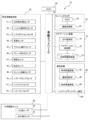
- FIG. 1 is a schematic configuration diagram of a head-up display device.
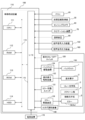
- FIG. 2 is a schematic configuration diagram of an automobile equipped with a head-up display device.
- FIG. 3 is a hardware configuration diagram of the head-up display device.
- FIG. 4 is a functional block diagram of the head-up display device.
- the automobile 10 includes a handle 12, a dashboard 14 in front of the handle 12, and a windshield glass (windshield 16), and a head-up display device that allows a driver to visually recognize a virtual image 18 in the dashboard 14.
- HUD Head Up Display
- the HUD 100 includes a video processing device 110 that forms image information, and a projection optical system 130 including a screen plate (diffusion plate) and an eyepiece optical system.
- the image processing apparatus 110 and the projection optical system 130 are accommodated in the dashboard 14, and the image light emitted from the projection optical system 130 is reflected toward the windshield 16 by the mirrors 6a and 6b. Therefore, the windshield 16 corresponds to a projection target member.
- the image light reflected from the windshield 16 enters the driver's eyes.
- the HUD 100 that reflects the image light on the windshield 16 will be described as an example.
- the HUD display optimization process described below can also be applied to a combiner type HUD.
- the mirror 6b is supported by the support member 6, and the angle of the mirror 6b can be adjusted by the support member 6 as will be described later.
- the light beam applied to the display element 2 from the backlight 1 is incident on the relay optical system 3 as an image light beam including image information displayed on the display element 2.
- the image information on the display element 2 is enlarged and projected onto the screen plate 4 by the imaging action in the relay optical system 3.
- the image information on the screen plate (diffusion plate) 4 passes through the eyepiece optical system 5 and is reflected by the mirrors 6a and 6b.
- the light beam projected onto the windshield 16 and reflected by the windshield 16 reaches the driver's eyes. As a result, the driver can see the virtual image 18.
- the driver also checks information such as speedometers and fuel gauges. Therefore, the HUD 100 is mounted on the automobile 10, and vehicle information of various instruments, information for alerting the driver, and navigation information from the car navigation device are displayed in front of the driver as a virtual image.
- the movement of the driver's line of sight during driving can be reduced, the time required for focusing the eyes can be shortened, and improvement in driving safety can be expected.
- the automobile 10 includes an ECU (Engine Control Unit) 20 that controls the body of the automobile 10, a vehicle information acquisition unit 30, a sensing camera 60, a navigation device 70, and a communication device 80. Connected to the in-vehicle network 50.
- the in-vehicle network 50 may be a CAN (Controller Area Network) or a wireless communication network.
- a millimeter wave radar 92 or an infrared sensor 94 may be provided as the external recognition sensor 90. Since the millimeter wave radar 92 has relatively high weather resistance, the detection result of the millimeter wave radar 92 (detection of relative distance, relative angle, and relative speed) is added to the detection result of the sensing camera 60, and obstacle detection processing (collision determination processing is performed). May be included). Further, the infrared sensor 94 may perform the obstacle detection process in combination with the detection result of the sensing camera 60 when the external light amount is small, for example, when traveling at night. These millimeter wave radar 92 and infrared sensor 94 are also connected to the in-vehicle network 50.
- the external recognition sensor 90 is not limited to the above example.
- the vehicle information acquisition part 30 is comprised by the sensor group which detects various vehicle information. Specifically, a direction indicator sensor 31 that outputs an operation signal (turn signal signal) of a direction indicator, a steering angle sensor 32 that detects a rotation angle of the handle 12 and outputs steering angle information, and outputs gear information.
- a direction indicator sensor 31 that outputs an operation signal (turn signal signal) of a direction indicator
- a steering angle sensor 32 that detects a rotation angle of the handle 12 and outputs steering angle information, and outputs gear information.
- a shift position sensor 33 that detects the number of rotations of the wheel of the automobile 10 and outputs speed information
- an accelerator operation sensor 35 that detects accelerator pedal depression amount and outputs accelerator operation information
- brake pedal depression Brake operation sensor 36 for detecting brake operation information by detecting the amount and presence / absence of parking brake operation
- illuminance sensor 37 for detecting external light quantity and outputting illuminance information
- chromaticity sensor 38 for performing an engine start sensor 3 for detecting engine ON / OFF information by detecting an operation of an ignition key
- a hazard lamp sensor 40 that detects the presence or absence of operation of the hazard lamp switch and outputs a hazard signal
- a headlight sensor 41 that detects the lighting state of the headlight and outputs headlight lighting information
- high / low sensor 42 for detecting switching is included.
- the above sensor is an example, and another type of sensor may be provided.
- the sensing camera 60 includes a camera 62 and an image processing unit 64 that performs image processing based on an output signal from the camera 62 and outputs image information.
- the sensing camera 60 captures a front landscape of the host vehicle and outputs a front image (also referred to as an outside scene image).
- a distance to an object (including an obstacle) included in the front image may be measured using a stereo camera including parallax and added to the image information.
- the distance to the obstacle, the relative speed, and the relative angle can be recognized by combining with the obstacle information detected by the external recognition sensor 90.
- the navigation device 70 includes a GPS receiving unit (GPS receiving antenna) 72 that receives a GPS signal, a map information storage unit 74 that stores map information, and calculates a current position based on the GPS signal and reads map information including the current position.
- GPS receiving antenna GPS receiving antenna
- map information storage unit 74 that stores map information, and calculates a current position based on the GPS signal and reads map information including the current position.
- a navigation control unit 76 for outputting navigation information.
- the communication device 80 includes a vehicle-to-vehicle communication unit 82, a road-to-vehicle communication unit 84, and a communication control unit 86 that performs communication control of the vehicle-to-vehicle communication unit 82 and the road-to-vehicle communication unit 84.
- the HUD 100 controls various operations of the HUD 100 and adjusts the angles of the video processing device 110 that generates a video signal to be projected, the display ON / OFF switch 120 of the HUD 100, and the mirror 6b.
- the mirror adjustment switch 122 that changes the reflection position of the image light
- the projection optical system 130 the display element driving device 132 that drives the display element 2
- the backlight driving device 134 that blinks the backlight 1, and the rotation angle of the mirror 6b.
- the IC tag reader 140 is illustrated in order to describe the embodiment in which the driver's attribute information is read from the driver's license, but the driver's attribute information (for example, age, gender, accident history, visual acuity)
- the driver's attribute information for example, age, gender, accident history, visual acuity
- the dashboard 14 is provided with the operation touch panel of the HUD 100, the IC tag reader 140 is not essential.
- the video processing apparatus 110 is configured by connecting a CPU 111, a RAM 112, a ROM 113, an HDD 114, and an I / O 115 via a bus 116. Each device is connected via the I / O 115.
- the video processing device 110 acquires the vehicle information directly from the vehicle information acquisition unit 30 via the ECU 20.
- the video processing device 110 acquires image information from the sensing camera 60 and navigation information from the navigation device 70.
- the video processing device 110 receives a vehicle-to-vehicle signal and a road-to-vehicle communication signal from the communication device 80.
- the voice input device 150 When performing voice input to the HUD 100, the voice input device 150 is connected to the I / O 115. Further, when projecting video from the HUD 100 and outputting audio, the audio output device 160 may be connected to the I / O 115.
- the video processing device 110 operates by supplying power from a power supply device 170 (such as a battery mounted in the automobile 10).
- a power supply device 170 such as a battery mounted in the automobile 10
- the video processing apparatus 110 includes an external information processing unit 210, a video processing unit 230, a distortion correction unit 240, a driver characteristic analysis unit 250, a driver characteristic information storage unit 260, and a mirror control unit 270.
- Each unit is configured such that the CPU 111, the RAM 112, and the software cooperate while the CPU 111 loads and executes the software that implements the function of each unit on the RAM 112.
- the external information processing unit 210 acquires vehicle information from the ECU 20 or the vehicle information acquisition unit 30 and outputs the vehicle information to the video processing unit 230.
- the external information processing unit 210 acquires external light information from the illuminance sensor 37 and An external light detection unit 214 that outputs brightness / darkness information to the video processing unit 230, an ON / OFF detection unit 216 that acquires an ON / OFF signal from the display ON / OFF switch 120 and controls the start or end of video projection by the HUD 100.
- Detecting an operation of the mirror adjustment switch 122 to generate a mirror operation signal outputting the mirror adjustment switch detection unit 218 to be output to the mirror control unit 270, a front image from the sensing camera 60, and executing an image analysis process,
- the image analysis unit 220 that outputs the analysis result to the video processing unit 230, and the inter-vehicle communication information and the road-to-vehicle communication from the communication device Communication information processing unit 222 that acquires communication information and outputs it to video processing unit 230, and IC tag information processing unit 224 that acquires driver attribute information from IC tag reading device 140 and outputs it to driver characteristic analysis unit 250. And including.
- the vehicle information processing unit 212 acquires vehicle information from the ECU 20 and the vehicle information acquisition unit 30 and outputs the vehicle information to the video processing unit 230.
- the acquired vehicle information is displayed as a virtual image on the HUD 100 as necessary. For example, the current vehicle speed, shift position (particularly rear), and an arrow indicating whether the direction indicator is on the left or right side are displayed as virtual images.
- an automatic driving switching signal is transmitted to the vehicle information processing unit 212 from the automatic driving switching switch 55 for switching the driving mode from the manual driving mode to the automatic driving mode.
- the signal is output to the video processing unit 230.
- the video processing unit 230 executes display control processing during automatic driving according to the automatic driving switching signal.
- the image analysis unit 220 analyzes a front image from the sensing camera 60 and recognizes an object (for example, a pedestrian, a two-wheeled vehicle, a front vehicle, and a next lane vehicle) captured in the image, and the recognition result is displayed as a video processing unit 230. Output to.
- the video processing unit 230 displays alert information for notifying the driver of the presence of the object using the recognition result as necessary.
- the image analysis unit 220 may execute an obstacle detection process based on the image information.
- obstacle information is output to the video processing unit 230.
- the video processing unit 230 uses the obstacle information (relative distance, relative angle, relative speed of the obstacle) and vehicle information (particularly, the vehicle speed information of the host vehicle) acquired from the ECU 20 or the vehicle information acquisition unit 30. And information to be notified to the driver, for example, warning information for avoiding a collision, information for prompting a collision avoidance operation, and warning information for a pedestrian or a motorcycle in a course direction are generated. .
- Free running distance reaction time (seconds) x Vs (2) Braking distance (m) ⁇ (Vh ⁇ 2) / 100 (3)
- Vs Vehicle speed before braking (second speed: m / second)
- Vh Vehicle speed before braking (speed: km / hour)
- Vh ⁇ 2 square of Vh
- equation (3) may be changed as appropriate in consideration of factors affecting the braking distance, such as road surface friction coefficient, road surface gradient, and the like. ) Is not limited.
- margins may be added as appropriate in the equations (1) and (2).
- the reaction time of equation (2) varies from driver to driver. Therefore, the video processing unit 230 adjusts the reaction time according to the driver's attribute information, for example, age and sex, and obtains a stop distance that matches the driver's attribute. As the stop distance is longer, the obstacle alarm information is displayed at an earlier timing.
- the driver's attribute information for example, age and sex
- the driver attribute information may include physical information related to the viewpoint position such as height and sitting height
- the video processing unit 230 may adjust the display position of the virtual image according to the position of the driver's eyes.
- the video processing unit 230 determines the display position of the virtual image based on the body information, and outputs the determined display position information to the mirror control unit 270.
- the mirror control unit 270 drives the mirror driving device 136 based on the display position information, and changes the image light reflection position on the windshield 16 to adjust the display position of the virtual image according to the driver.
- the driver may adjust the angle of the mirror 6b by operating the mirror adjustment switch 122.
- the projection position of the windshield 16 may be changed using a micro electro mechanical system instead of the mirror angle adjustment mechanism.
- age information may be included in the driver's attribute information, and the video processing unit 230 may adjust the display position of the virtual image by determining the width of the visual field area according to the driver's age. For example, control may be performed so that a virtual image is displayed near the center of the visual field for elderly people and a virtual image is displayed in the peripheral region of the visual field for young people.
- the driver characteristic analysis unit 250 acquires driver identification information as driver attribute information, and associates the vehicle speed and brake operation timing information with the driver identification information while driving as the driver characteristic information. Stored in the person characteristic information storage unit 260. Based on the driver characteristic information, the driver characteristic of the driver, for example, the speed of the timing of the brake operation, is analyzed, and the analysis result is output to the video processing unit 230. The video processing unit 230 adjusts the display timing of the alarm information with reference to the analysis result of the driver characteristics.
- the distortion correction unit 240 performs distortion correction processing such as keystone correction on the video signal generated by the video processing unit 230, outputs the corrected video signal to the display element driving device 132, and outputs the corrected video signal to the display element 2. A video based on the video signal is displayed.
- the video processing unit 230 acquires navigation information from the navigation device 70, calculates the travel distance from the current position to the destination and the required travel time, and performs a display corresponding to this. Also good.
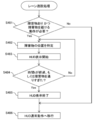
- FIG. 5 is a flowchart showing the flow of the initial operation of the HUD 100.
- the video processing device 110 acquires vehicle information from the ECU 20 or the vehicle information acquisition unit 30 (S102), and the IC tag reader 140 is operated by the driver.
- the attribute information is read and output to the video processing apparatus 110 (S103).
- the driver's attribute information is acquired by the IC tag reading device 140 reading the tag information of the driver's license, but the driver's attribute information may be input from the operation panel of the HUD 100. At that time, the driver may input the attribute information every time, or the driver who drives the automobile 10 or the name of the family who owns the automobile 10 (may be a nickname), age, and sex are stored in advance. The driver's selection operation may be performed from the operation panel.
- Brightness level adjustment processing is executed (S105).
- the brightness level adjustment process will be described with reference to FIG.
- FIG. 6 is a flowchart showing the flow of brightness level adjustment processing.
- the video processing unit 230 calculates an appropriate brightness level based on the external light information acquired from the illuminance sensor 37 by the external light detection unit 214 (S1051). At this time, the brightness level according to the age of the driver may be further adjusted.
- the external light detection unit 214 determines whether or not the brightness level needs to be changed. If necessary (S1052 / Yes), the video processing unit 230 outputs a light amount adjustment signal to the backlight driving device 134, and the video light A brightness level is set (S1053).
- the external light detection unit 214 determines that the brightness level does not need to be changed (S1502 / No), the brightness level setting value is maintained as it is, and the process is terminated.
- the video display mode is determined (S106). Since there are a variety of video signals that can be displayed on the HUD 100, the type of video signal desired to be displayed in advance, for example, a right turn or left turn arrow based on speed information and navigation information, may be selected and stored. In addition, the attribute information of the driver and the type of video signal that the driver wants to display are stored in association with each other, and an image that suits the driver's preference is displayed based on the attribute information acquired in step 103. May be.
- the distortion correction unit 240 executes distortion correction processing (S107), and outputs an ON signal of the display element 2 to the display element driving device 132 (S108).
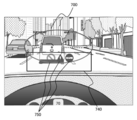
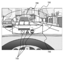
- 7A and 7B are diagrams showing display examples for young people and elderly people.
- FIG. 7A is a display example for elderly people
- FIG. 7B is a display example for young people.
- 8A and 8B are diagrams showing another display example for young people and elderly people, in which FIG. 8A is a display example for elderly people, and FIG. 8B is a display example for young people.
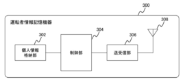
- FIG. 9 is a diagram showing a configuration of a driver information storage device (for example, a driver's license having an IC tag).
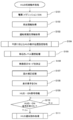
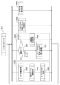
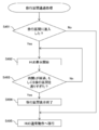
- FIG. 10 is a flowchart showing the flow of display position setting processing for each young person and elderly person.
- the field of view 700 of the elderly is generally narrower than the field of view 720 of the young (see FIG. 7B). Therefore, when the driver is an elderly person, the virtual image 750 is displayed at a position closer to the center of the visual field in the virtual image display area 740 (see FIG. 7A). On the other hand, when the driver is a young person, the virtual image display area 740 is widely used, and the virtual image 750 is displayed on the periphery of the virtual image display area 740 that is not used for the elderly (see FIG. 7B).
- FIG. 8A content with low urgency is displayed below the virtual image display area 740, that is, at a position similar to that of a young person (see FIG. 8B),
- the content with high urgency may be selectively displayed in a region near the center of the visual field of the virtual image display area 740.
- the inter-vehicle distance display 752 is displayed in a region near the center of the visual field of the virtual image display area 740.
- the display position (virtual image display area 740) is determined within a range that does not conflict with the laws and regulations related to the forward visual field.
- FIG. 9 shows the configuration of the driver information storage device 300.
- the personal information storage unit 302 stores driver personal information (corresponding to attribute information), the control unit 304 executes personal information transmission processing, and the transmission / reception unit. 306 and a wireless antenna 308.
- the personal information storage unit 302 may be configured using an IC chip or memory, the control unit 304 may be configured using a microcomputer, and the transmission / reception unit 306 may be configured using a short-range wireless device (eg, ZigBee or IC tag).
- personal information stores age, height, presence / absence of vision correction, driving history, and travel distance. If the personal information storage unit 302 is a rewritable memory, the driving history and travel distance may be updated as needed.
- the driver information storage device 300 is a driver's license
- the data may be updated when the driver's license is updated.
- the driver information storage device 300 may create a device in which attribute information is written for reading by the HUD 100. If the driver's license or the like is equipped with a short-range wireless device function, the driver's license or the like is used. May be. Moreover, you may use public cards, such as a Juki net card and my number card.
- the transmission / reception area of the short-range wireless is about 1 m, or is configured so as not to read attribute information other than the driver from the front passenger seat or the rear seat by reading it in contact.
- the IC tag reading device 140 reads out the driver attribute information from the driver information storage device 300 (S1041), extracts age information from the attribute information read by the IC tag information processing unit 224 (S1042), and sends it to the video processing unit 230. Output.
- the video processing unit 230 determines whether the driver is an elderly person based on the age information.
- a virtual image position will be changed (S1044).
- the change mode of the virtual image position only changes the arrangement of contents in the virtual image display area 740 and does not change the position of the virtual image display area 740 with respect to the windshield 16.
- the position of the virtual image display area relative to the windshield 16 may be changed by changing the angle of the mirror 6b via the mirror control unit 270 without changing the arrangement of the content in the virtual image display area.
- step S105 After changing the virtual image display area position or when it is determined that the person is not an elderly person (S1043 / No), the process proceeds to step S105 (S1045).
- the IC tag reading device 140 is always in a standby state when the power of the HUD 100 is turned on, and when the driver information storage device 300 enters the short-range wireless reception area, the attribute information is automatically extracted from the driver information storage device 300. You may comprise so that information may be read.
- the driver may bring the driver information storage device 300 into contact with the IC tag reader 140 when getting on.
- driving the driver's license without carrying it by performing a contact operation leads to suppression of unlicensed driving.
- suitable display of HUD can be performed according to the width of the field of view accompanying the driver's age. Furthermore, it is possible to alert a higher level by selectively changing the display position of content with high urgency.
- the image of the in-vehicle camera and the image may be analyzed to perform person recognition processing to identify the driver or estimate its age. Furthermore, the identification of the driver and the estimation of the age may be performed by combining the result of the person recognition process and the information read from the driver information storage device 300.
- FIG. 11 is a flowchart showing the flow of processing of normal operation of the HUD.
- the normal operation here refers to an operation that is repeated until the HUD initial setting process is completed and the power is turned off next time.
- the normal operation of the HUD includes an environment setting process (S300) for performing a suitable display of the HUD, a suitable display process for each operation mode according to the automatic operation mode or the manual operation mode (S400), Autonomous vehicle approach alert display processing (S500) and external stimulus display processing (S600) for preventing drowsiness of the driver regardless of the driving mode and low-awareness driving where attention is reduced are executed in parallel. Is done.
- S300 Environment setting process
- S320 mirror adjustment process
- S340 brightness level adjustment process
- S360 display video change process
- the mirror adjustment switch detection unit 218 In the mirror adjustment process (S320), the mirror adjustment switch detection unit 218 always waits for reception of an operation signal from the mirror adjustment switch 122. When the mirror adjustment switch detection unit 218 receives the operation signal, it outputs an operation signal to the mirror control unit 270, and the mirror control unit 270 drives the mirror driving device 136 to change the mirror angle.
- the processing content of the brightness level adjustment processing (S340) is the same as that of the above-described brightness level adjustment processing (S105). However, the illuminance sensor 37 monitors changes in the amount of external light due to the influence of time or weather. Continue to adjust the brightness level according to the amount of external light.
- the video processing unit 230 acquires vehicle information and displays vehicle information and content suitable for the driver as needed.
- the dashboard 14 includes an automatic driving changeover switch 55, and the vehicle information processing unit 212 of the video processing device 110 acquires an automatic driving signal from the automatic driving changeover switch 55.
- the video processing unit 230 determines that it is a manual driving mode by the driver during normal times (S402: manual driving mode), learns the driver characteristics of the driver, and executes an optimization process for HUD display (S410). .
- the video processing unit 230 determines the automatic driving mode (S402 / automatic driving mode), and executes the automatic driving display process (S450).
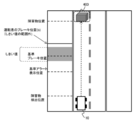
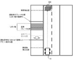
- FIG. 12 is a diagram illustrating a brake position of the driver whose reaction speed is within an allowable range.
- FIG. 13 is a diagram illustrating a brake position of a driver whose reaction speed is outside the allowable range (slow).
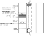
- FIG. 14 is a diagram illustrating an alert display position for a driver with a slow reaction speed.
- FIG. 15 is a diagram illustrating a brake position of a driver with a slow reaction speed after changing to the alert display position of FIG. 14.
- the automobile 10 executes an obstacle detection process using an image from the sensing camera 60 and an output signal from the millimeter wave radar 92 while traveling.
- the brake operation start position (reference brake position) for stopping the automobile 10 before colliding with the obstacle 400 is obtained based on the relative distance to the obstacle 400 and the braking distance based on the vehicle speed of the automobile 10.
- the reference brake position is closer than the obstacle 400 by a distance required for stopping.
- the threshold value (margin distance) of the brake position operation position for stopping the automobile 10 before the collision is obtained from the individual difference in the driver's reaction speed and the brake pedal depression amount. .
- a reference alert display position at which alert display is started to obtain a brake operation at the reference brake position is determined with reference to the reference brake position.
- the reference alert display position is a response speed from when the average driver recognizes the alert until the brake operation is started, for example, a margin distance that takes into account individual differences to the distance traveled by the car 10 in 1 to 2 seconds. Set the position before the reference brake position.
- the driver actually depresses the brake pedal, that is, when the driver's brake position (a) is within the threshold value range, this driver is a normal driver who has no problem with the reaction speed.
- the threshold value defines a deviation position of the brake operation timing allowed from the reference brake position.
- the alert display position at this time corresponds to “alert display position adjusted according to driver characteristics” in FIG.
- the driver brake position after adjustment of the alert display position is closer to the front and falls within the threshold range, so that collision with the obstacle 400 is avoided.
- step 410 HUD display optimization processing learned driver characteristics] to learn the driver characteristics and optimize the HUD display in this way.
- the driver characteristic data update process and the HUD display timing control with reference to the driver characteristic data are performed in parallel.
- the update process of the driver characteristic data will be described, and then the display control process of the HUD with reference to the driver characteristic data will be described.
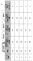
- FIG. 16 is a diagram illustrating a configuration of a driver characteristic data table stored in the driver characteristic information storage unit 260.
- FIG. 17 is a flowchart showing the flow of the driver characteristic data table update process.
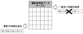
- FIG. 18 is a diagram showing the concept of the driver characteristic data table update process.
- FIG. 16 is a driver characteristic data table 500 relating to the driver A.
- the driver characteristic data table 500 includes a “data number” indicating the data acquisition order, “vehicle speed” at that time, “time from obstacle detection to alert display”, “time from alert display to brake use”, “brake Includes “distance to obstacles during use” and “threshold judgment (inner: 0, out; 1)” indicating whether or not the driver brake position is within the threshold. . Similar records may be recorded for a plurality of drivers (drivers B, C, and D in the example of FIG. 16). In addition, each record of the driver characteristic data table 500 of FIG. 16 is an example, and may include other records.
- the image analysis unit 220 acquires image data from the sensing camera 60, performs subject recognition processing of the image, and executes obstacle detection processing.
- the communication information processing unit 222 acquires a communication signal from the communication device 80 and executes the obstacle detection process.
- the time at which the obstacle is detected and the obstacle detection time T (A) are output from the image analysis unit 220 or the communication information processing unit 222 to the video processing unit 230 and the driver characteristic analysis unit 250. (S301).
- the driver characteristic analysis unit 250 also acquires vehicle speed information at the obstacle detection time T (A) (S302). Thereafter, the vehicle speed information at each time point is continuously acquired and used for distance calculation later.
- the video processing unit 230 acquires the obstacle detection time T (A) and the vehicle speed information at that time, determines a grace period from the obstacle detection time to the alert display according to the vehicle speed, and distorts the obstacle alert information. Output to the unit 240.
- the distortion correction unit 240 outputs a video signal for displaying the obstacle alert information to the display element driving device 132, and the content based on the obstacle alert information is displayed as a virtual image.
- the driver characteristic analysis unit 250 acquires the alert information output time and alert display time T (B) from the video processing unit 230 (S303).
- the driver characteristic analysis unit 250 acquires brake information from the vehicle information acquisition unit, and acquires the time at that time as the brake use time T (C) for the obstacle (S304).
- the obstacle detection time T (A) and the alert The display time T (B) can be handled by associating the obstacle detection time T (A) used as the output trigger of the obstacle alert information with the alert display time T (B) by the video processing unit 230.
- the brake use time T (C) is equal to the brake use time T (C), which is the time when the brake information by the first brake pedal operation performed at a time after the alert display time T (B) is output. May be associated with the alert display time T (B).
- the evaluation of the driver characteristics may be performed using an average value of a plurality of data.
- the driver characteristic analysis unit 250 calculates the time between the obstacle detection time T (A) and the alert display time T (B) (S305).
- the driver characteristic analyzer 250 calculates the time between the alert display time T (B) and the brake use time T (C) (S306). The order of steps 305 and 306 may be reversed.
- the driver characteristic analysis unit 250 uses the vehicle speed continuously acquired in step 302 and the time between the alert display time T (B) and the brake use time T (C), and uses the brake from the alert display time T (B). The travel distance of the automobile 10 until time T (C) is calculated (S307).
- the position of the vehicle 10 at the brake use time T (C), that is, the driver brake position, is determined using the moving distance in step 307, and it is determined whether or not this is within the threshold value (S308).
- the driver characteristic analysis unit 250 updates the driver characteristic data table 500 corresponding to the current driver (S309).
- the data for the latest five times are held for each driver.
- the driver characteristic data table 500 is updated, if there is a vacancy in the number of data held (for example, only the latest three data), the latest data is added to the vacant area.
- the oldest information is deleted from the data table and the latest information is added as shown in FIG.
- FIGS. 19A to 19C and FIG. 19A to 19C are diagrams showing display examples of display control processing of HUD with reference to driver characteristic data
- FIG. 19A is an example of an initial value display screen
- FIG. 19B is an example of a display screen in which the display color is changed
- FIG. Shows an example of a display screen that displays text information in combination with the display color.
- FIG. 20 is a flowchart showing the flow of HUD display control processing with reference to driver characteristic data.
- operator characteristic data may be sufficient.
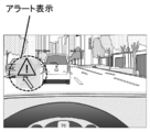
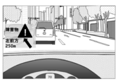
- the alert display color (FIG. 19A) in the initial setting state is changed to a clearer display color for the elderly, or to a correction color that matches the deterioration of the color recognition ability of the elderly. It may be done (FIG. 19B).
- text may be added and displayed (FIG. 19C).
- the driver characteristic analysis unit 250 acquires information (name, etc.) uniquely identifying the driver based on the driver attribute information acquired from the IC tag reader 140, and the driving associated with the identification information.
- the person characteristic data table 500 is read (S321).
- the driver characteristic analysis unit 250 determines to control the display timing and display color of the HUD for the driver with the initial values.
- the result is output to the video processing unit 230.
- the video processing unit 230 performs display control with this initial value (S323).
- the determination condition in step 322 may be that all the values in the “threshold determination” record are “0”, or the number of data outside the threshold may be N or less.
- the driver characteristic analysis unit 250 performs the timing adjustment process based on the data outside the threshold value, and determines the display start timing setting value of the adjusted alert. Is output to the video processing unit 230 (S324). At this time, the adjustment of the display color may also be determined. In this step 324, how much earlier the display timing may be determined based on the number of data outside the threshold.
- the video processing unit 230 performs an alert display control process with the adjusted display timing, display color, and display mode (S324).
- step 329 an initial setting display screen is displayed (see FIG. 19A), and in step 330, an alert is displayed in an adjusted display mode that matches the characteristics of the driver (see FIGS. 19B and 19C).
- Favorable display of HUD can be performed by adjusting the display timing control and display color according to the driver's characteristics.
- the brake operation delay can be alleviated and the safety during driving can be further increased.
- the driver can quickly read and display the display contents, and have an effect of correctly understanding.
- FIG. 21 is a diagram illustrating a display example when a road is given to another vehicle.
- FIG. 22 is a diagram illustrating a display example when a road is given from another vehicle.
- FIG. 23 is a diagram illustrating a display example when the own vehicle deviates from the traveling lane.
- FIG. 24 is a diagram illustrating a display example during traveling in the slow section.
- HUD 100 executes automatic operation display processing during automatic operation or in the transition period of automatic operation.
- the driver does not know the status of inter-vehicle communication and does not know who has given up the driving lane with the parallel running vehicle. The driver feels uneasy when changing lanes or starting in that situation.
- the automatic driving control device for example, it may be realized as a function of the ECU 20
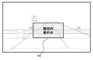
- a “slowing through railroad crossing” message 458 is displayed.
- Other examples of slow trains are roads around kindergartens, preschools, schools, etc.
- FIG. 25 shows a process flow when interrupted from another vehicle in the transfer control process (when a road is transferred to another vehicle).
- FIG. 26 shows the flow of processing when the own vehicle interrupts (transfers the road from another vehicle) in the transfer control processing.
- FIG. 27 shows the flow of lane departure processing.
- FIG. 28 is a flowchart showing the flow of the slow section passing process. The concession control process, the lane departure process, and the slow section passing process are started when the trigger event of each process occurs during the execution of the automatic driving display process.
- the interrupt request of the other vehicle is not limited to inter-vehicle communication, and is realized by photographing the driver of the other vehicle with the sensing camera 60, and the image analysis unit 220 performing image analysis processing and determining the driver's gesture image. May be.
- the position of the other vehicle is specified based on the image from the sensing camera 60 (S462), and the HUD 100 notifies the driver that there is an interrupt of the other vehicle. Is displayed (see FIG. 21) (S463).
- the specification of the other vehicle position is not limited to image analysis. For example, you may implement
- step 462 Until the time t elapses or the lane movement of the other vehicle is completed (S464 / No), the processing from step 462 is repeated. By repeating this, it is possible to cause the HUD to display an interrupt following the movement of the other vehicle.
- the time t may be set in advance, or the driver may adjust the set value according to his / her preference.
- Completion of lane movement of other vehicles may be realized by receiving a movement completion message from another vehicle via inter-vehicle communication.
- the other vehicle may be imaged by the sensing camera 60, and the lane movement completion of the other vehicle may be determined by image recognition by the image analysis unit 220.
- the self-driving vehicle and the other vehicle that are driving automatically communicate with each other and send an interrupt request signal to the other vehicle (S472). If there is an interrupt permission response from the other vehicle (S473 / Yes), the position of the other vehicle is determined. Identification (S474) and interrupt display (see FIG. 22) are started (S475). If there is no interrupt permission response from the other vehicle (S473 / No), the routine proceeds to HUD normal operation.
- step 474 Until the time t elapses or the lane movement of the host vehicle is completed (S476 / No), the processing from step 474 is repeated. By repeating this, the HUD can be interrupted and displayed following the movement of the host vehicle.
- the time t may be set in advance, or the driver may adjust the set value according to his / her preference.
- the position of the obstacle is specified (S482), and a lane deviation display (see FIG. 23) for avoiding the obstacle is performed (S483).
- step 482 the processing from step 482 is repeated.
- the determination process of whether or not the vehicle has passed the obstacle the obstacle is photographed by the sensing camera 60 and the obstacle can not be detected by the image analysis unit 220, or the distance from the obstacle is obtained by the image recognition process, and the distance is determined.
- the determination material may be that the distance has been within the range specified in advance, or that the obstacle has been detected to be rearward from the vehicle by the image recognition process.
- slow-pass passage processing As shown in FIG. 28, when the own vehicle enters the slowing section, the following flows are triggered by this (S491 / Yes). Presence / absence of the slow section may be realized by the image analysis unit 220 performing image analysis processing on the image of the sensing camera 60 to detect a slow sign, a railroad crossing, and the vicinity of the top of the hill. Alternatively, slow section information may be acquired by road-to-vehicle communication. If it does not correspond to the above event (S491 / No), it shifts to the HUD normal operation.
- step 492 Until the time t elapses or passes through the slow section (S493 / No), the processing from step 492 is repeated.
- the driver can be informed of the behavior of the vehicle and other vehicles, and the driver's anxiety during automatic driving can be reduced. Note that during automatic driving, the driver does not always see the HUD display, so the driver may be notified by outputting sound in synchronization with the display.
- FIG. 29 is a diagram illustrating an alert display example for a preceding vehicle during automatic driving.
- FIG. 30 is a diagram illustrating an alert display example for another vehicle that is driving automatically in an adjacent lane.
- FIG. 31 is a diagram showing an alert display example using text data together.
- FIG. 32 is a diagram illustrating an example in which an alert is displayed for a plurality of autonomous driving vehicles.
- FIG. 33 is a flowchart showing a flow of alert display processing for notifying the approach of an autonomous driving vehicle.
- the position of the autonomous driving vehicle is determined based on the image analysis result from the sensing camera 60, and the alert display 501 (see FIG. 29) is superimposed and displayed on the preceding vehicle during the automatic driving according to the position. .
- an alert display 502 (see FIG. 30) and an arrow 503 indicating which vehicle is automatically driven may be superimposed on a vehicle traveling in an adjacent lane.
- text information 505 including the inter-vehicle distance from the autonomous driving vehicle may be displayed (see FIG. 31).
- alert displays 506 and 507 may be displayed for each autonomous driving vehicle while a plurality of autonomous driving vehicles are traveling in the vicinity of the own vehicle (see FIG. 32). The text display of the alert displays 506 and 507 can be omitted.
- a relative distance from the autonomous driving vehicle is acquired (S512). This distance may be calculated by obtaining information indicating the self-position from another vehicle that is automatically driving by inter-vehicle communication, or sensing the vehicle when the vehicle that is automatically driving is specified by the inter-vehicle communication information. The distance may be calculated by imaging with the camera 60 and image analysis processing by the image analysis unit 220.
- the video processing unit 230 acquires the relative distance information, and returns to Step 511 and does not display an alert until the relative distance falls within a predetermined value (S513 / No).
- the video processing unit 230 determines that the relative distance is within the predetermined value (S513 / Yes)
- the video processing unit 230 displays an approach alert indicating the approach of the autonomous driving vehicle (S514). Thereafter, the approach alert is continuously displayed (S514) until the relative distance from the autonomous driving vehicle displaying the approach alert exceeds a predetermined value (S515 / No).
- the approach alert is terminated (S516), and the operation returns to the HUD normal operation (S517).
- the driver can be alerted by displaying an alert that the autonomous driving vehicle has approached. Note that during automatic driving, the driver does not always see the HUD display, so the driver may be notified by outputting sound in synchronization with the display.
- FIG. 34 is a diagram illustrating a normal display example.
- FIG. 35 is a diagram showing an example of external stimulus display.
- FIG. 36 is a flowchart showing the flow of the external stimulus display process.
- the HUD 100 extracts long straight roads and highways from map information and position information, and performs prior display and real-time stimulus display.
- the image analysis unit 220 analyzes the image of the sensing camera 60 and measures the external stimulus amount.
- the amount of change in the outside scene captured in the image is used as the external stimulus amount.
- the amount of change in the outside scene may be determined based on the magnitude of the outside scene contrast, or may be determined based on the amount of time-series change in the image. For example, when traveling in an urban area, the outside scene contrast tends to increase. In addition, when the traffic volume is relatively large and the vehicles ahead change frequently, the time-series change amount of the image tends to increase. In this way, when the change amount of the outside scene is equal to or greater than the threshold value, the driver's attention is hardly reduced, so normal display including no stimulus display is performed (see FIG. 34).
- the video processing unit 230 acquires the current position information and the destination information from the navigation device 70 (S612).
- the navigation device 70 is not used (S611 / No), since the travel distance cannot be assumed, the operation is started (S616).
- the video processing unit 230 calculates the travel distance and travel time set by the navigation device 70 (S613), and if the travel distance is less than the threshold value and the travel time is also less than the threshold value (S614 / Yes), Operation is started without displaying a caution image (S616).
- This threshold value is a distance threshold value and a time threshold value provided to determine whether the route has a risk of low-speed driving.
- the video processing unit 230 displays a warning video and a break standard (S615), and alerts the user before starting driving. Thereafter, the driver starts driving (S616).
- a simple question may be asked to the driver before starting driving, the driver's physical condition may be grasped from the answer to the question, and the threshold value referred to in steps 614 and 619 may be changed. For example, when the driver's physical condition is not good, the alerting effect to the driver can be enhanced by changing to a threshold value lower than a preset threshold value.
- the video processing unit 230 acquires vehicle information (travel start time, travel start distance) from the vehicle information acquisition unit 30 (S617), and calculates continuous travel time and distance (S618).
- This continuous travel distance is the travel distance and time after reading new driver attribute information. Alternatively, it may be the continuous travel distance and time after the destination is set in the navigation and the driving is started.
- the external scene change amount is calculated as the external stimulus amount.
- the threshold value may be set to 100 km for the continuous travel distance and 1 hour for the travel time.
- the image analysis unit 220 analyzes the image photographed by the sensing camera 60, and calculates the external stimulus amount (outside scene change amount) (S620).
- the video processing unit 230 causes the HUD 100 to A stimulus image is displayed (S622).
- the stimulus video display end condition may be set as appropriate, for example, when the stimulus display is performed after a predetermined time has elapsed, or when it is repeatedly displayed a predetermined number of times with an arbitrary time interval.
- the stimulus display may always be performed regardless of the amount of the external stimulus.
- the stimulus display may always be performed regardless of the amount of the external stimulus.
- the stimulus display may be performed not only in the above-mentioned travel distance / time and continuous travel distance / hour driving, but also in the sleepy time zone (1-3 am, 3-4 midnight).
- the video processing unit 230 may acquire traffic jam information with a road-to-vehicle communication signal, acquire travel information from the navigation device 70, and display a break point recommendation.
- This break point becomes a stimulus display, and it is possible to provide a driver with a proposal for taking an effective break while preventing a reduction in attention in a traffic jam.
Landscapes
- Engineering & Computer Science (AREA)
- Chemical & Material Sciences (AREA)
- Combustion & Propulsion (AREA)
- Transportation (AREA)
- Mechanical Engineering (AREA)
- Physics & Mathematics (AREA)
- Remote Sensing (AREA)
- Radar, Positioning & Navigation (AREA)
- General Physics & Mathematics (AREA)
- Automation & Control Theory (AREA)
- Optics & Photonics (AREA)
- Traffic Control Systems (AREA)
- Instrument Panels (AREA)
- Navigation (AREA)
Abstract
車両の運転者の前方に配置された被投影部材に映像光を投射して虚像を表示するヘッドアップディスプレイ装置であって、前記運転者の属性情報を取得する属性情報取得部と、属性情報に基づいて、運転者ごとに表示内容及び表示位置の少なくとも一つを決定する映像処理部と、を備える。
Description
本発明は、ヘッドアップディスプレイ装置及びその表示制御方法に関する。
ヘッドアップディスプレイ装置に関する技術として、特許文献1には「車両情報表示制御装置は、車両の運転者の視野に情報を表示するヘッドアップディスプレイ(HUD)を制御する。情報表示判断部は、車両の状況に関する情報を取得し、取得した情報に基づいて、HUDで表示すべき情報を判断する。車両情報表示制御装置は、車両の前方を撮影した画像を取得する画像処理部と、運転者の視線の方向を検出する視線方向検出部と、車両の前方の画像および運転者の視線の方向に基づいて、運転者の視野に対応する画像である仮想視野画像を構築する仮想視野構築部と、仮想視野画像および車両の状況に基づいて、HUDで表示する情報のレイアウトを決定する(要約抜粋)」構成が開示されている。
また特許文献2には「車速を検出する車速センサと、この車速センサにより検出された車速が大きいほど、表示画像の表示位置を運転者の有効視野の中心側に移動させる制御部とを備えている(要約抜粋)」と記載されている。
更に特許文献3には「表示部と、車両状態検知部と、運転者状態検知部と、車両の状態情報と運転者の状態情報とに基づいて、運転者の覚醒度を判定する覚醒度判定部とを備えた車両用表示装置であって、覚醒度判定部の判定に基づいて、表示部の表示を変更する表示変更部を備える事により、表示部を覚醒度判定部が判定した覚醒度に応じて変化させる事が出来るので、運転者は最適な覚醒度で運転作業を行う事が可能になる(要約抜粋)」と記載されている。
ヘッドアップディスプレイ装置が表示する画像(映像)の視認性を向上させることは、運転の安全性を向上させるためにも有用である。この点で、特許文献1では運転者に視線方向に合わせてレイアウトを変更し、特許文献2では車速に応じて表示位置を変えることで視認性の向上を図っているものの、個々の運転者の属性、例えば高齢者は若年者に比べて視野が狭くなるといった運転者の属性を考慮した表示制御はされていない。
また、特許文献3では運転者の覚醒度に応じた表示制御を行っているが、そもそも覚醒度が低下した状態では注意喚起の表示すら見落としてしまう可能性があることが懸念される。このようにヘッドアップディスプレイ装置の表示技術には更なる工夫の余地が残されているのが実情である。
本発明は上記実情に鑑みてなされたものであり、運転者の属性に応じた表示を行うことで、ヘッドアップディスプレイ装置の好適表示が行える技術を提供することを目的とする。
上記した課題を解決するために、例えば本発明は、車両の運転者の前方に配置された被投影部材に映像光を投射して虚像を表示するヘッドアップディスプレイ装置であって、前記運転者の属性情報を取得する属性情報取得部と、前記属性情報に基づいて、運転者ごとに表示内容及び表示位置の少なくとも一つを決定する映像処理部と、を備えることを特徴とする。
本発明によれば、運転者の属性に応じた表示を行うことで、ヘッドアップディスプレイ装置の好適表示が行える技術を提供することができる。なお、上記した以外の課題、構成及び効果は、以下の実施形態の説明により明らかにされる。
以下の実施の形態においては、便宜上その必要があるときは、複数のセクションまたは実施の形態に分割して説明する。以下の実施の形態において、要素の数等(個数、数値、量、範囲等を含む)に言及する場合、特に明示した場合及び原理的に明らかに特定の数に限定される場合等を除き、その特定の数に限定されるものではなく、特定の数以上でも以下でもよい。なお、以下の実施の形態において、その構成要素(処理ステップ等も含む)は、特に明示した場合及び原理的に明らかに必須であると考えられる場合等を除き、必ずしも必須ではない。
また、以下の実施の形態における各構成、機能、処理部、処理手段等は、それらの一部または全部を、例えば集積回路その他のハードウェアとして実現しても良い。また、後述する各構成、機能、処理部、処理手段等は、コンピュータ上で実行されるプログラムとして実現しても良い。すなわち、ソフトウェアとして実現しても良い。各構成、機能、処理部、処理手段等を実現するプログラム、テーブル、ファイル等の情報は、メモリやハードディスク、SSD(Solid State Drive)等の記憶装置、ICカード、SDカード、DVD等の記憶媒体に格納することができる。
図1から図4を用いて、ヘッドアップディスプレイ装置の基本構成について説明する。図1は、ヘッドアップディスプレイ装置の概略構成図である。図2は、ヘッドアップディスプレイ装置を搭載する自動車の概略構成図である。図3は、ヘッドアップディスプレイ装置のハードウェア構成図である。図4はヘッドアップディスプレイ装置の機能ブロック図である。
図1に示すように、自動車10はハンドル12、ハンドル12の前面のダッシュボード14、ウィンドシールドガラス(フロントガラス16)を備え、ダッシュボード14内に運転者に虚像18を視認させるヘッドアップディスプレイ装置(Head Up Display:以下「HUD」と略記する)100を収容する。
HUD100は、画像情報を形成する映像処理装置110及びスクリーン板(拡散板)や接眼光学系を含む投影光学系130を備える。この映像処理装置110及び投影光学系130がダッシュボード14内に収容され、投影光学系130から出射された映像光をミラー6a、6bでフロントガラス16に向かって反射する。従って、フロントガラス16は被投影部材に相当する。フロントガラス16から反射された映像光は、運転者の眼に入射する。本実施形態では、フロントガラス16に映像光を反射させるHUD100を例に説明するが、コンバイナタイプのHUDでも以下で説明するHUD表示の好適化処理を適用することができる。なお、ミラー6bは支持部材6によって支持されており、後述するように支持部材6によってミラー6bの角度が調整できる。
投影光学系130では、バックライト1から表示素子2に照射された光束が、表示素子2に表示された映像情報を含んだ映像光束として、リレー光学系3に入射する。リレー光学系3での結像作用により、表示素子2上の映像情報は拡大されスクリーン板4上に拡大投写される。
次に、スクリーン板(拡散板)4上の画像情報は、接眼光学系5を通ってミラー6a、6bで反射される。そしてフロントガラス16に投射され、フロントガラス16で反射した光束が運転者の眼に到達する。これにより運転者は虚像18を見ることができる。
運転中には、前走車の確認(ブレーキランプや右折・左折ランプの点灯)や、その手前の道路の路面の確認(落下物の有無など)や、さらに手前で道路の端の自転車・歩行者の確認などを行っている。また、運転者はスピードメータや燃料計などの情報も確認する。そこで、HUD100を自動車10に装備し、HUD100に各種計器類の車両情報や、運転者への注意を喚起するための情報、またカーナビゲーション装置からのナビゲーション情報を虚像として運転者の前方に表示することにより、運転中における運転者の視線方向の移動を小さくでき、かつ眼のピント合わせに要する時間を短縮することができ、運転の安全性の向上が期待できる。
図2に示すように、自動車10には自動車10の車体制御を行うECU(Engine Control Unit)20、車両情報取得部30、センシングカメラ60、ナビゲーション装置70、及び通信装置80が搭載され、各々が車載ネットワーク50に接続される。車載ネットワーク50は、CAN(Controller Area Network)でもよいし、無線通信網でもよい。
また外界認識センサ90としてミリ波レーダ92や赤外線センサ94を備えてもよい。ミリ波レーダ92は耐候性が比較的高いのでセンシングカメラ60による検知結果にミリ波レーダ92の検知結果(相対距離、相対角度、相対速度の検知)を加えて障害物検出処理(衝突判定処理を含む)を行ってもよい。また赤外線センサ94は外光量が少ない状況、例えば夜間走行時にセンシングカメラ60による検知結果と合わせて障害物検出処理を行ってもよい。これらミリ波レーダ92及び赤外線センサ94も車載ネットワーク50に接続される。外界認識センサ90は上記例に限定されない。
車両情報取得部30は、各種車両情報を検知するセンサ群により構成される。具体的には、方向指示器の操作信号(ターンシグナル信号)を出力する方向指示器センサ31、ハンドル12の回転角度を検知して操舵角情報を出力するハンドル操舵角センサ32、ギア情報を出力するシフトポジションセンサ33、自動車10の車輪の回転数を検知して速度情報を出力する車速センサ34、アクセルペダルの踏込量を検出してアクセル操作情報を出力するアクセル操作センサ35、ブレーキペダルの踏込量及びパーキングブレーキの操作の有無を検出してブレーキ操作情報を検出するブレーキ操作センサ36、外光量を検知して照度情報を出力する照度センサ37、外光を検知してその色度情報を出力する色度センサ38、イグニンションキーの操作を検知してエンジンON/OFF情報を検出するエンジン始動センサ39、ハザードランプスイッチの操作の有無を検知してハザード信号を出力するハザードランプセンサ40、ヘッドライトの点灯状態を検知しヘッドライト点灯情報を出力するヘッドライトセンサ41、及びヘッドライトのハイ/ローの切り替えを検知するハイ/ローセンサ42を含む。上記センサは一例であり、別種のセンサを備えてもよい。
センシングカメラ60には、カメラ62、及びカメラ62からの出力信号を基に画像処理を行って画像情報を出力する画像処理部64を備える。センシングカメラ60は自車の前方風景を撮影し、前方画像(外景画像ともいう)を出力する。視差を含むステレオカメラを用いて前方画像に含まれるオブジェクト(障害物も含まれる)までの距離を測定し、画像情報に付加してもよい。単視点カメラの場合は、外界認識センサ90が検出した障害物情報と組み合わせることで障害物までの距離、相対速度、相対角度が認識できる。
ナビゲーション装置70は、GPS信号を受信するGPS受信部(GPS受信アンテナ)72、地図情報を記憶する地図情報記憶部74、及びGPS信号を基に現在位置を演算し現在位置を含む地図情報を読み出してナビゲーション情報を出力するナビゲーション制御部76を含む。
通信装置80は、車車間通信部82、路車間通信部84、及び、車車間通信部82、路車間通信部84の通信制御を行う通信制御部86を含む。
図3に示すように、HUD100は、HUD100の諸動作を制御するとともに、投射する映像信号を生成する映像処理装置110、HUD100の表示ON/OFFスイッチ120、ミラー6bの角度を調整してフロントガラス16における映像光の反射位置を変化させるミラー調整スイッチ122、投影光学系130、表示素子2を駆動させる表示素子駆動装置132、バックライト1を点滅させるバックライト駆動装置134、ミラー6bの回転角度を変化させるミラー駆動装置136、運転者が携帯する運転免許証に内蔵されたICタグから運転者の属性情報を読み取るICタグ読取装置140を備える。本実施形態では、運転者の属性情報を運転免許証から読み取る実施形態について後述するためにICタグ読取装置140を図示しているが、運転手の属性情報(例えば年齢、性別、事故歴、視力情報)の入手部材として別の部材、例えばダッシュボード14にHUD100の操作用タッチパネルを備える場合は、ICタグ読取装置140は必須ではない。
映像処理装置110は、バス116を介して、CPU111、RAM112、ROM113、HDD114、及びI/O115のそれぞれが接続されて構成される。そしてI/O115を介して各装置が接続される。
映像処理装置110は、ECU20を経由してまたは車両情報取得部30から直接車両情報を取得する。
映像処理装置110は、センシングカメラ60から画像情報を、ナビゲーション装置70からナビゲーション情報を取得する。
また映像処理装置110は、通信装置80から車車間信号及び路車間通信信号を受信する。
HUD100へ音声入力を行う場合は音声入力装置150をI/O115に接続する。またHUD100から映像を投射すると共に音声出力をする際には音声出力装置160をI/O115に接続してもよい。
映像処理装置110は電源装置170(自動車10に搭載されたバッテリー等)からの給電により動作する。
図4に示すように、映像処理装置110は、外部情報処理部210、映像処理部230、歪み補正部240、運転者特性解析部250、運転者特性情報記憶部260、及びミラー制御部270を含む。各部は、CPU111が各部の機能を実現するソフトウェアをRAM112にロードして実行中に、CPU111、RAM112、及びソフトウェアが協働して構成される。
外部情報処理部210は、詳細にはECU20または車両情報取得部30から車両情報を取得して映像処理部230に出力する車両情報処理部212、照度センサ37から外光情報を取得し外界の明暗を示す明暗情報を映像処理部230に出力する外光検出部214、表示ON/OFFスイッチ120からON/OFF信号を取得してHUD100による映像投影の開始または終了を制御するON/OFF検出部216、ミラー調整スイッチ122の操作を検出してミラー操作信号を生成し、ミラー制御部270に出力するミラー調整スイッチ検出部218、センシングカメラ60からの前方画像を取得して画像解析処理を実行し、解析結果を映像処理部230に出力する画像解析部220と、通信装置80から車車間通信情報及び路車間通信情報を取得し、映像処理部230へ出力する通信情報処理部222と、ICタグ読取装置140から運転者の属性情報を取得し、運転者特性解析部250に出力するICタグ情報処理部224と、を含む。
車両情報処理部212は、ECU20や車両情報取得部30から車両情報を取得し、映像処理部230に出力する。取得した車両情報は、必要に応じてHUD100に虚像として表示される。例えば現在の車速、シフトポジション(特にリア)や、方向指示器が左右どちらの側にONになっているかを示す矢印が虚像として表示される。
自動車10に自動運転機能が搭載されている場合には、運転モードを手動運転モードから自動運転モードに切り替えるための自動運転切替スイッチ55から自動運転切替信号が車両情報処理部212に送信され、この信号が映像処理部230に出力される。映像処理部230は、自動運転切替信号に応じて自動運転時の表示制御処理を実行する。
画像解析部220は、センシングカメラ60からの前方画像を解析して画像中に撮像されたオブジェクト(例えば、歩行者、二輪車、前方車両、隣車線車両)を認識し、認識結果を映像処理部230に出力する。映像処理部230は必要に応じて認識結果を用いてオブジェクトの存在を運転者に知らせるための注意喚起情報を表示する。
また画像解析部220は、画像情報を基に障害物検出処理を実行してもよい。障害物を検出すると映像処理部230に障害物情報を出力する。映像処理部230は、障害物情報(障害物の相対距離、相対角度、相対速度)、及びECU20や車両情報取得部30から取得した車両情報(特に自車の車速情報)を用いて、障害物との衝突判定処理を実行し、運転手に報知すべき情報、例えば衝突回避のための警報情報、衝突回避動作を促す情報、また進路方向にいる歩行者、二輪車などに対する注意喚起情報を生成する。
一般に、時速Vhで走行中の車両の停止距離は、下式で求められる。
停止距離=空走距離+制動距離・・・(1)
空走距離=反応時間(秒)×Vs・・・(2)
制動距離(m)≒(Vh^2)/100・・・(3)
Vs:制動前の車速(秒速:m/秒)
Vh:制動前の車速(時速:km/時)
Vh^2:Vhの2乗
なお、式(3)は路面摩擦係数、路面勾配等、制動距離に影響を与える要因を考慮して適宜変更してもよく、制動距離の算出式は式(3)に限定されない。また式(1)(2)も適宜マージンを加えてもよい。
停止距離=空走距離+制動距離・・・(1)
空走距離=反応時間(秒)×Vs・・・(2)
制動距離(m)≒(Vh^2)/100・・・(3)
Vs:制動前の車速(秒速:m/秒)
Vh:制動前の車速(時速:km/時)
Vh^2:Vhの2乗
なお、式(3)は路面摩擦係数、路面勾配等、制動距離に影響を与える要因を考慮して適宜変更してもよく、制動距離の算出式は式(3)に限定されない。また式(1)(2)も適宜マージンを加えてもよい。
式(2)の反応時間は、運転者ごとに異なる。そこで映像処理部230は、運転者の属性情報、例えば年齢、性別に応じて反応時間を調整し、運転者の属性に合った停止距離を求める。そして停止距離が長いほど、より早いタイミングで障害物の警報情報を表示する。
また運転者の属性情報に身長、座高のような視点位置に係る身体情報を含んでおき、映像処理部230が虚像の表示位置を運転者の眼の位置に合わせて調整してもよい。映像処理部230は、身体情報を基に虚像の表示位置を決定し、ミラー制御部270に決定した表示位置情報を出力する。ミラー制御部270はその表示位置情報を基にミラー駆動装置136を駆動し、フロントガラス16における映像光反射位置を変化させて虚像の表示位置を運転者に合わせて調整する。
また、運転者がミラー調整スイッチ122を操作して、ミラー6bの角度を調整してもよい。更に、ミラー角度の調整機構の代わりに微小電気機械システム(Micro Electro Mechanical Systems)を用いてフロントガラス16の投射位置を変更してもよい。
また運転者の属性情報に年齢情報を含んでおき、映像処理部230が運転者の年齢に応じた視野領域の広狭を判断し、虚像の表示位置を調整してもよい。例えば、高齢者には視野中心付近に虚像を表示し、若年者には視野周辺領域に虚像を表示するように制御してもよい。
運転者特性解析部250は、運転者の属性情報として運転者識別情報を取得し、その運転者の運転中に運転者識別情報と関連付けて車速やブレーキ操作のタイミング情報を運転者特性情報として運転者特性情報記憶部260に蓄積する。運転者特性情報を基に運転者の運転者特性、例えばブレーキ操作のタイミングの早さなどを解析し、映像処理部230にその解析結果を出力する。映像処理部230は、運転者特性の解析結果を参照して、警報情報の表示タイミングを調整する。
歪み補正部240は映像処理部230が生成した映像信号に対してキーストン補正などの歪み補正処理を実行し、補正後の映像信号を表示素子駆動装置132に出力して表示素子2に補正後の映像信号に基づく映像が表示される。
また図4では図示を省略するものの、映像処理部230はナビゲーション装置70からナビゲーション情報を取得し、現在位置から目的地までの走行距離や走行所要時間を演算し、これに応じた表示を行ってもよい。
図5は、HUD100の初期動作の流れを示すフローチャートである。自動車10のイグニッションキーを回して電源装置170がONになると(S101)、映像処理装置110はECU20や車両情報取得部30から車両情報を取得し(S102)、ICタグ読取装置140が運転者の属性情報を読み取って映像処理装置110に出力する(S103)。
本実施形態では、運転者の属性情報をICタグ読取装置140が運転免許証のタグ情報を読み取ることで取得するが、HUD100の操作パネルから運転者の属性情報を入力させてもよい。その際、運転者が毎回属性情報を入力してもよいし、予め自動車10を運転する運転者や、例えば自動車10を保有する家族の名前(ニックネームでもよい)、年齢、性別を記憶させておき、操作パネルから今回の運転者の選択操作を行ってもよい。
続いて若年者、高齢者別の表示位置設定処理を行う(S104)。この詳細は後述する。
明るさレベル調整処理が実行される(S105)。図6を参照して明るさレベル調整処理について説明する。図6は、明るさレベル調整処理の流れを示すフローチャートである。図6に示すように、外光検出部214が照度センサ37から取得した外光情報を基に映像処理部230は適切な明るさレベルを算出する(S1051)。このとき、運転者の年齢に応じた明るさレベルを更に調整してもよい。
外光検出部214は明るさレベルの変更要否を判断し、必要であれば(S1052/Yes)、映像処理部230はバックライト駆動装置134に対して光量調整信号を出力し、映像光の明るさレベルを設定する(S1053)。
外光検出部214が明るさレベルの変更は不要と判断すると(S1502/No)、明るさレベルの設定値を現状のまま維持し、処理を終了する。
次に映像表示モードを決定する(S106)。HUD100で表示可能な映像信号は多種あるので、その中から予め表示させたい映像信号の種類、例えば速度情報、ナビゲーション情報に基づく右折、左折の矢印等を選択させて記憶しておいてもよい。また運転者の属性情報とその運転者が表示させたい映像信号の種類とを予め対応させて記憶させておき、ステップ103で取得した属性情報を基にその運転者の好みに合った映像を表示してもよい。
歪み補正部240が歪み補正処理を実行し(S107)、表示素子駆動装置132に対して表示素子2のON信号を出力する(S108)。
その後、表示ON/OFFスイッチ120が操作されるまで待機し(S109、S110/No)、ON/OFF検出部216がHUD-ON信号を検出すると(S110/Yes)HUD通常動作が開始する(S111)。
[運転者の属性に応じた表示設定処理]
以下図7Aから図10を参照して運転者の属性に応じた表示設定処理について説明する。図7A、7Bは、若年者及び高齢者に対する表示例を示す図であって、図7Aは高齢者向け表示例、図7Bは若年者向け表示例である。図8A、8Bは、若年者及び高齢者に対する別の表示例を示す図であって、図8Aは高齢者向け表示例、図8Bは若年者向け表示例である。図9は、運転者情報記憶機器(例えば、ICタグを備えた運転免許証)の構成を示す図である。図10は、若年者、高齢者別の表示位置設定処理の流れを示すフローチャートである。
以下図7Aから図10を参照して運転者の属性に応じた表示設定処理について説明する。図7A、7Bは、若年者及び高齢者に対する表示例を示す図であって、図7Aは高齢者向け表示例、図7Bは若年者向け表示例である。図8A、8Bは、若年者及び高齢者に対する別の表示例を示す図であって、図8Aは高齢者向け表示例、図8Bは若年者向け表示例である。図9は、運転者情報記憶機器(例えば、ICタグを備えた運転免許証)の構成を示す図である。図10は、若年者、高齢者別の表示位置設定処理の流れを示すフローチャートである。
図7Bに示すように、一般に高齢者の視野700は若年者の視野720よりも狭い(図7B参照)。そこで、運転者が高齢者である場合には、虚像表示エリア740のうち、視野中心により近い位置に虚像750を表示する(図7A参照)。一方、運転者が若年者の場合は、虚像表示エリア740を広く使い、高齢者に対しては用いない虚像表示エリア740の周縁部に虚像750を表示する(図7B参照)。
他の表示例として、図8Aのように、高齢者に対しても、緊急性が低いコンテンツは虚像表示エリア740の下方、すなわち若年者と同様の位置(図8B参照)に表示させておき、緊急性が高いコンテンツを選択的に虚像表示エリア740の視野中心に近い領域に表示させてもよい。図8A、8Bの例では、車間距離が予め定めた距離しきい値未満となった場合に、車間距離表示752を虚像表示エリア740の視野中心に近い領域に表示する。なお、いずれの場合においても、前方視野に関する法規制に抵触しない範囲で表示位置(虚像表示エリア740)を決定する。
図9は、運転者情報記憶機器300の構成であり、運転者の個人情報(属性情報に相当する)を格納した個人情報格納部302、個人情報の送信処理を実行する制御部304、送受信部306、及び無線アンテナ308を備える。個人情報格納部302はICチップやメモリ、制御部304はマイコン、送受信部306は近距離無線装置(たとえば ZigBeeやICタグ)を用いて構成してもよい。個人情報は、年齢、身長、視力矯正の有無、運転歴、走行距離が格納される。個人情報格納部302が書き換え可能なメモリであれば、運転歴、走行距離は随時データを更新してもよい。また、運転者情報記憶機器300が運転免許証である場合は、運転免許証の更新時にデータを更新してもよい。
運転者情報記憶機器300は、HUD100の読取用に属性情報を書き込んだものを作成してもよいし、運転免許証等に近距離無線装置機能が搭載されていれば、運転免許証等を用いてもよい。また住基ネットカードやマイナンバーカードのような公的なカードを用いてもよい。
近距離無線の送受信エリアは1m程度、または接触して読み取らせることにより、助手席や後部席からは運転者以外の属性情報を読み取らないように構成することが望ましい。
図10を参照して、若年者、高齢者別の表示位置設定処理の流れを説明する。ICタグ読取装置140は運転者情報記憶機器300から運転者の属性情報を読み出し(S1041)、ICタグ情報処理部224が読み取った属性情報から年齢情報を抽出し(S1042)、映像処理部230に出力する。映像処理部230は、年齢情報を基に運転者が高齢者であるか否かを判断する。
高齢者であれば(S1043/Yes)、虚像位置を変更する(S1044)。虚像位置の変更態様は、虚像表示エリア740内におけるコンテンツの配置を変えるだけで、虚像表示エリア740のフロントガラス16に対する位置は変更しない。
別の態様として虚像表示エリア内におけるコンテンツの配置は変えず、ミラー制御部270を介してミラー6bの角度を変更し、フロントガラス16に対する虚像表示エリアの位置を変更してもよい。
虚像表示エリア位置の変更後、または高齢者でないと判断された場合は(S1043/No)、ステップS105へ進む(S1045)。
上記において、ICタグ読取装置140は、HUD100の電源がONになると常時待ち受け状態となり、近距離無線の受信エリア内に運転者情報記憶機器300が入ると自動的に運転者情報記憶機器300から属性情報を読み取るように構成してもよい。
また、乗車する際に運転者がICタグ読取装置140に運転者情報記憶機器300を接触させてもよい。運転者情報記憶機器として運転免許証を用いる場合は、接触動作をさせることで運転免許証を不携帯で運転することや、無免許運転の抑止につながる。
上記表示設定処理により、運転者の年齢に伴う視野の広狭に応じてHUDの好適な表示が行える。更に、緊急性が高いコンテンツについて選択的に表示位置を変更することで、より高度な注意喚起が行える。なお、車内カメラを備える場合、車内カメラの映像と、その映像を解析して人物認識処理を行い、運転者の特定、またはその年齢を推定しても良い。さらには、人物認識処理の結果と、運転者情報記憶機器300から読み取った情報とを組み合わせることで運転者の特定や年齢の推定を行っても良い。
図11を参照してHUDの通常動作処理について説明する。図11は、HUDの通常動作の処理の流れを示すフローチャートである。ここでいう通常動作とはHUDの初期設定処理が終了し、次に電源がOFFにされるまでに繰り返される動作をいう。
図11に示すように、HUDの通常動作は、HUDの好適表示を行うための環境設定処理(S300)と、自動運転モードまたは手動運転モードに応じた運転モード別好適表示処理(S400)と、自動運転車接近アラート表示処理(S500)と、運転モードに関らず運転者の眠気防止また注意力が低下する覚低走行を防止するための外部刺激表示処理(S600)とが並行処理で実行される。
[S300:環境設定処理]
環境設定処理S300の一例として、ミラー調整処理(S320)、明るさレベル調整処理(S340)、表示映像変更処理(S360)がある。これら3つの処理の順序は図11に限定されず、前後が適宜入れ替わってもよい。
環境設定処理S300の一例として、ミラー調整処理(S320)、明るさレベル調整処理(S340)、表示映像変更処理(S360)がある。これら3つの処理の順序は図11に限定されず、前後が適宜入れ替わってもよい。
ミラー調整処理(S320)では、ミラー調整スイッチ検出部218が常にミラー調整スイッチ122からの操作信号の受信を待機する。そしてミラー調整スイッチ検出部218が操作信号を受信すると、ミラー制御部270に対して操作信号を出力し、ミラー制御部270がミラー駆動装置136を駆動してミラー角度を変更する。明るさレベル調整処理(S340)の処理内容は、既述の明るさレベル調整処理(S105)と同様であるが、時間の経過や天候等の影響に伴う外光量の変化を照度センサ37で監視し続け、外光量に応じた明るさレベルの調整を繰り返す。映像表示モード決定処理(S106)では、映像処理部230が車両情報を取得し、随時車両情報及び運転者に合ったコンテンツを表示する。
[S400:運転モード別好適表示処理]
ダッシュボード14に自動運転切替スイッチ55を備え、映像処理装置110の車両情報処理部212は、自動運転切替スイッチ55から自動運転信号を取得する。映像処理部230は、通常時は運転者による手動運転モードであると判定し(S402:手動運転モード)、運転者の運転者特性を学習してHUD表示の最適化処理を実行する(S410)。
ダッシュボード14に自動運転切替スイッチ55を備え、映像処理装置110の車両情報処理部212は、自動運転切替スイッチ55から自動運転信号を取得する。映像処理部230は、通常時は運転者による手動運転モードであると判定し(S402:手動運転モード)、運転者の運転者特性を学習してHUD表示の最適化処理を実行する(S410)。
車両情報処理部212が自動運転信号を受信すると映像処理部230は自動運転モードと判定し(S402/自動運転モード)、自動運転表示処理を実行する(S450)。
[S410:ドライバ特性を学習したHUDの表示最適化処理]
図12から図14を参照してドライバ特性を学習したHUDの表示最適化処理の概念と効果について説明する。図12は、反応速度が許容範囲内の運転者のブレーキ位置を示す図である。図13は、反応速度が許容範囲外(遅い)の運転者のブレーキ位置を示す図である。図14は、反応速度が遅い運転者に対するアラート表示位置を示す図である。図15は、図14のアラート表示位置に変更した後の反応速度が遅い運転者のブレーキ位置を示す図である。
図12から図14を参照してドライバ特性を学習したHUDの表示最適化処理の概念と効果について説明する。図12は、反応速度が許容範囲内の運転者のブレーキ位置を示す図である。図13は、反応速度が許容範囲外(遅い)の運転者のブレーキ位置を示す図である。図14は、反応速度が遅い運転者に対するアラート表示位置を示す図である。図15は、図14のアラート表示位置に変更した後の反応速度が遅い運転者のブレーキ位置を示す図である。
自動車10は走行中にセンシングカメラ60からの画像やミリ波レーダ92からの出力信号を用いて障害物検出処理を実行する。そして例えば図12に示すように障害物400を検知したとする。障害物400に衝突する前に自動車10を停止させるためのブレーキ操作開始位置(基準ブレーキ位置)は、障害物400までの相対距離と自動車10の車両速度に基づく制動距離とを基に求められる。基準ブレーキ位置は障害物400よりも停止に要する距離以上手前である。そして基準ブレーキ位置を基に、運転者の反応速度やブレーキペダルの踏込操作量の個人差から、衝突前に自動車10を停車させるためのブレーキ位置操作位置のしきい値(マージン距離)が求められる。更に基準ブレーキ位置を基準とし、その基準ブレーキ位置でブレーキ操作を行わせるためにアラートの表示を開始する基準アラート表示位置が求められる。基準アラート表示位置は、平均的な運転者がアラートを認知してからブレーキ操作を開始するまでの反応速度、例えば1~2秒間に自動車10が走行する距離に個人差を考慮したマージン距離を加えて基準ブレーキ位置よりも手前に設定する。
この状態で、運転者が実際にブレーキペダルを踏み込んだ位置、すなわち運転者のブレーキ位置(a)がしきい値の範囲内にある場合、この運転者は反応速度に問題がない通常の運転者として扱われる。なおしきい値は、基準ブレーキ位置から許容されるブレーキ操作のタイミングのずれ位置を規定したものである。
一方、図13に示すように運転者が実際にブレーキペダルを踏み込んだ位置、すなわち運転者のブレーキ位置(b)がしきい値の範囲外であって障害物400に近い側にある場合、この運転者は反応速度が遅い運転者として扱われる。よって、運転者の反応速度が遅いことを考慮して、基準アラート表示位置よりも更に手前においてアラートを表示させる。このときのアラート表示位置が図14の「運転者特性に合わせて調整したアラート表示位置」に相当する。
「運転者特性に合わせて調整したアラート表示位置」は基準アラート位置よりも手前にあるので、基準アラート位置よりもより早いタイミングで障害物400の存在を通知するアラートが表示される。そのため、より早いタイミングで運転者がブレーキペダルの踏込動作を開始できる。その結果、図15に示すようにアラート表示位置の調整後の運転者ブレーキ位置はより手前になり、しきい値の範囲内に収まるので障害物400への衝突が回避される。
このように運転者の特性を学習してHUDの表示の最適化を図るのが、ステップ410の[ドライバ特性を学習したHUDの表示最適化処理]の意図である。HUDの表示最適化処理では、運転者特性データの更新処理と、運転者特性データを参照したHUDの表示タイミング制御とが並行して進められる。以下、運転者特性データの更新処理について説明し、続いて運転者特性データを参照したHUDの表示制御処理について説明する。
(運転者特性データの更新処理)
図16は、運転者特性情報記憶部260に格納された運転者特性データテーブルの構成を示す図である。図17は運転者特性データテーブルの更新処理の流れを示すフローチャートである。図18は運転者特性データテーブルの更新処理の概念を示す図である。
図16は、運転者特性情報記憶部260に格納された運転者特性データテーブルの構成を示す図である。図17は運転者特性データテーブルの更新処理の流れを示すフローチャートである。図18は運転者特性データテーブルの更新処理の概念を示す図である。
図16は、運転者Aに関する運転者特性データテーブル500である。運転者特性データテーブル500は、データの取得順序を示す「データ番号」、その時の「車速」、「障害物検出からアラート表示までの時間」、「アラート表示からブレーキ使用までの時間」、「ブレーキ使用時の障害物までの距離」、及び運転者ブレーキ位置がしきい値内にあるか否かの判定結果を示す「しきい値判定(内:0,外;1)」の各レコードを含む。また、同様のレコードを複数の運転者(図16の例では運転者B、C、D)について記録するとよい。なお、図16の運転者特性データテーブル500の各レコードは一例であり、他のレコードを含んでもよい。
図17を参照して、運転者特性データテーブル500の作成処理について説明する。HUD100の主電源投入後、センシングカメラ60から画像データを画像解析部220が取得し、画像の被写体認識処理を行って障害物検出処理を実行する。
障害物検出処理を車車間/路車間通信で行う場合には、通信情報処理部222が通信装置80から通信信号を取得し障害物検出処理を実行する。障害物が検出された場合には、画像解析部220または通信情報処理部222から映像処理部230及び運転者特性解析部250に障害物を検出した時刻、障害物検出時刻T(A)を出力する(S301)。
運転者特性解析部250は、障害物検出時刻T(A)の車速情報も取得する(S302)。以後、各時点の車速情報を取得し続け、後に距離算出に用いる。
映像処理部230は、障害物検出時刻T(A)及びそのときの車速情報を取得し、車速に応じて障害物検出時刻からアラート表示までの猶予時間を決定し、障害物アラート情報を歪み補正部240に出力する。歪み補正部240は障害物アラート情報を表示させるための映像信号を表示素子駆動装置132に出力し、障害物アラート情報に基づくコンテンツが虚像として表示される。運転者特性解析部250は、映像処理部230からアラート情報を出力した時刻、アラート表示時刻T(B)を取得する(S303)。
運転者特性解析部250は、車両情報取得部からブレーキ情報を取得し、その時の時刻を障害物に対するブレーキ使用時刻T(C)として取得する(S304)。ここで、障害物検出時刻T(A)、アラート表示時刻T(B)、及びブレーキ使用時刻T(C)の対応付けの仕方は様々考えられるが、例えば障害物検出時刻T(A)とアラート表示時刻T(B)とは、映像処理部230が障害物アラート情報の出力トリガとして用いた障害物検出時刻T(A)をアラート表示時刻T(B)に関連付けることで対応がとれる。また、ブレーキ使用時刻T(C)は、アラート表示時刻T(B)よりも後の時刻に行われた最初のブレーキペダル操作によるブレーキ情報が出力された時刻をブレーキ使用時刻T(C)と一律に決めてアラート表示時刻T(B)に関連付けてもよい。運転者の特性の評価は、複数回のデータの平均値を用いて行ってもよい。
運転者特性解析部250は、障害物検出時刻T(A)及びアラート表示時刻T(B)間の時間を算出する(S305)。
運転者特性解析部250は、アラート表示時刻T(B)及びブレーキ使用時刻T(C)間の時間を算出する(S306)。ステップ305、306の順序は逆でもよい。
運転者特性解析部250は、ステップ302以降で取得し続けた車速とアラート表示時刻T(B)及びブレーキ使用時刻T(C)間の時間を用いて、アラート表示時刻T(B)からブレーキ使用時刻T(C)までの自動車10の移動距離を算出する(S307)。
ステップ307の移動距離を用いてブレーキ使用時刻T(C)における自動車10の位置、すなわち運転者ブレーキ位置を決定し、これがしきい値内にあるかを判定する(S308)。
この判定結果を含めて、運転者特性解析部250は、現在の運転者に対応する運転者特性データテーブル500を更新する(S309)。図16では、各運転者について直近の5回分のデータを保持するようにしている。運転者特性データテーブル500の更新に際してはデータ保持数に空きがある(例えば直近3回分のデータしかない)場合は、最新のデータを空き領域に追加する。一方、データ保持数に空きがない場合は、図18に示すように、一番古い情報をデータテーブルから削除して最新の情報を追加する。
(運転者特性データを参照したHUDの表示制御処理)
図19A-19C及び図20を参照して運転者特性データを参照したHUDの表示制御処理について説明する。図19A-19Cは、運転者特性データを参照したHUDの表示制御処理の表示例を示す図であり、図19Aは初期値表示画面例、図19Bは表示色を変更した表示画面例、図19Cは表示色にテキスト情報を合わせて表示した表示画面例を示す。図20は、運転者特性データを参照したHUDの表示制御処理の流れを示すフローチャートである。
図19A-19C及び図20を参照して運転者特性データを参照したHUDの表示制御処理について説明する。図19A-19Cは、運転者特性データを参照したHUDの表示制御処理の表示例を示す図であり、図19Aは初期値表示画面例、図19Bは表示色を変更した表示画面例、図19Cは表示色にテキスト情報を合わせて表示した表示画面例を示す。図20は、運転者特性データを参照したHUDの表示制御処理の流れを示すフローチャートである。
以下では説明の便宜のため、表示タイミング制御処理に加えて表示内容の変更処理も行う場合を例に挙げて説明するが、表示タイミング制御処理だけを実行してもよい。また運転者特性データに合わせた好適表示例として表示内容の変更処理だけを行う態様であってもよい。例えば、初期設定状態のアラート表示色(図19A)に対して、高齢者に対してはより明確な表示色に変更したり、高齢者の色認識能力の低下に合わせた補正色に変更したりしてもよい(図19B)。更に、表示色の変更に加えてテキストを追加して表示してもよい(図19C)。
図20を参照して運転者特性データを参照したHUDの表示制御処理の流れについて説明する。運転者特性解析部250は、ICタグ読取装置140から取得した運転者の属性情報を基に、運転者を固有に識別する情報(名前等)を取得し、この識別情報に対応付けられた運転者特性データテーブル500を読み出す(S321)。
通常の運転者として取り扱えるかを判定するため判定条件を充足する場合(S322/Yes)、運転者特性解析部250は、当該運転者に対するHUDの表示タイミング及び表示色を初期値で制御すると決定し、その結果を映像処理部230に出力する。映像処理部230は、この初期値で表示制御を行う(S323)。ステップ322の判定条件は「しきい値判定」レコードの値が全て「0」としてもよいし、しきい値外のデータがN個以下としてもよい。
一方、判定条件不充足であれば(S322/No)、運転者特性解析部250は、しきい値外のデータに基づくタイミング調整処理を行い、調整後のアラートの表示開始タイミング設定値を決定して映像処理部230に出力する(S324)。このとき表示色の調整も合わせて決定してもよい。本ステップ324において、しきい値外のデータの数を基に、表示タイミングを早める際に、どの程度早くするかも合わせて決定してもよい。
映像処理部230は、調整後の表示タイミングや表示色、表示態様でアラート表示制御処理を行う(S324)。
走行中に障害物を検知し(S325、S326)、初期設定のアラート表示位置に到達(S327)、または運転者の特性に合わせて調整したアラート表示位置に到達(S328)すると、アラートを表示する(S329、S330)。ステップ329では初期設定の表示画面が表示され(図19A参照)、ステップ330では、運転者の特性に合わせた調整後の表示態様でアラートが表示される(図19B、19C参照)。
運転者の特性に応じた表示タイミング制御や表示色を調整することにより、HUDの好適表示が行える。特に反応速度の低下に合わせてアラートの表示タイミングを早めることで、ブレーキ操作遅延を緩和し、運転時の安全性をより高めることができる。さらに、運転者にとって視認しやすい表示を行うことで、運転者は表示内容を速やかに読み取り、また正しく理解する効果が得られる。
[S450:自動運転表示処理]
以下図21から図24を参照して自動運転時におけるHUDの表示例について説明する。図21は、他車に道を譲る場合の表示例を示す図である。図22は、他車から道を譲られる場合の表示例を示す図である。図23は、自車が走行レーンを逸脱する場合の表示例を示す図である。図24は、徐行区間走行中の表示例を示す図である。
以下図21から図24を参照して自動運転時におけるHUDの表示例について説明する。図21は、他車に道を譲る場合の表示例を示す図である。図22は、他車から道を譲られる場合の表示例を示す図である。図23は、自車が走行レーンを逸脱する場合の表示例を示す図である。図24は、徐行区間走行中の表示例を示す図である。
自動運転時若しくは自動運転の移行期にHUD100は自動運転表示処理を実行する。自動運転時、運転者は車車間通信の状況が分からず並走車との間でどちらが走行レーンを譲ったのかがわからない。その状況でレーンチェンジをしたり、発進をすると運転者は不安を感じる。
また自動運転時に、自動運転制御装置(例えばECU20の一機能として実現してもよい)が徐行すべき区間を認識できているか、運転者は把握したいという要望がある。
そこで自動運転中に他車と車車間通信を行い、走行レーンの譲り合い処理を行ってその結果をHUDで表示する。例えば他車に道を譲り、他車が自車前に割り込む場合には、道を譲った他車上に「割り込みます」451というメッセージと、割り込み方向を示す矢印452とを表示する(図21参照)。このような表示は、実際に割り込みを行う前に表示する。
また、T字路や交差点で二台の車両が停止している際に、他車から自車に道が譲られた場合には、他車上に「道を譲っています」453というメッセージと、自車の進行方向を示す矢印454とを表示する(図22参照)。更に他車が自車の通過待ちをしていることを示す停止マーク455も他車の実景に重畳表示する。
また、自車の進行方向の路肩に駐車中の他車があり、これをよけるためにレーンチェンジ、若しくはレーンを逸脱する場合、障害物に「障害物あり レーンを逸脱します」456というメッセージを重畳表示するとともに、自車の走行予定経路を矢印457で示す(図23参照)。このような表示は、実際にレーンチェンジ等を行う前に表示する。
更に徐行区間、例えば踏切内を徐行する場合は「踏切内徐行中」メッセージ458を表示する。徐行区間の他例として、幼稚園、保育園、学校等の周辺道路がある。
次に図25から図28を参照して、自動運転表示処理の流れについて説明する。図25は、譲り合い制御処理において他車から割り込まれる場合(他車に道を譲る場合)の処理の流れを示す。図26は、譲り合い制御処理において自車が割り込む場合(他車から道を譲ってもらう場合)の処理の流れを示す。図27は、レーン逸脱処理の流れを示す。図28は、徐行区間通過処理の流れを示すフローチャートである。譲り合い制御処理、レーン逸脱処理、徐行区間通過処理は、自動運転表示処理の実行中に各処理のトリガ事象の発生に伴い開始する。
(譲り合い制御処理:他車から割り込まれる場合)
図25に示すように、自動運転中の自車と他車とが車車間通信を行い、他車から割り込み要求信号を受信する(S461)と、これをトリガとして下記の各フローが開始する。他車の割り込み要求は、車車間通信に限定されず、センシングカメラ60で他車の運転者を撮影し、画像解析部220が運転者のジェスチャ画像を画像解析処理して判断することで実現してもよい。
図25に示すように、自動運転中の自車と他車とが車車間通信を行い、他車から割り込み要求信号を受信する(S461)と、これをトリガとして下記の各フローが開始する。他車の割り込み要求は、車車間通信に限定されず、センシングカメラ60で他車の運転者を撮影し、画像解析部220が運転者のジェスチャ画像を画像解析処理して判断することで実現してもよい。
割り込み要求信号を承諾しない場合は(S461/No)、HUD通常動作へ移行する。
割り込み要求信号を承諾する場合は(S461/Yes)、センシングカメラ60からの画像を基に他車の位置を特定し(S462)、HUD100が他車の割り込みがあることを運転者に通知するための表示(図21参照)を開始する(S463)。他車位置の特定は画像解析に限定されない。例えば車車間通信で他車から位置情報を取得することで実現してもよい。
時間tが経過、若しくは他車のレーン移動が完了するまで(S464/No)、ステップ462以下の処理を繰り返す。この繰り返しにより、他車の移動に追随してHUDに割り込み表示をさせることができる。なお時間tは事前に設定されていてもよいし、運転者が設定値に対して自分の好みで調整してもよい。
他車のレーン移動の完了は、車車間通信で他車から移動完了のメッセージを受信することで実現してもよい。また、センシングカメラ60で他車を撮像し、画像解析部220による画像認識で他車のレーン移動完了を判断することで実現してもよい。
時間tが経過、若しくは他車のレーン移動が完了すると(S464/Yes)、割り込み表示を終了し(S465)、HUD通常動作へ移行する(S466)。
(譲り合い制御処理:自車が割り込む場合)
図26に示すように、自車が他のレーンへの移動が必要であり、かつ並走レーンに他車が存在してレーン移動ができない事象が生じると、これをトリガとして下記の各フローが開始する(S471/Yes)。上記事象に該当しない場合は(S471/No)、HUD通常動作へ移行する。
図26に示すように、自車が他のレーンへの移動が必要であり、かつ並走レーンに他車が存在してレーン移動ができない事象が生じると、これをトリガとして下記の各フローが開始する(S471/Yes)。上記事象に該当しない場合は(S471/No)、HUD通常動作へ移行する。
自動運転中の自車と他車とが車車間通信を行い、他車に割り込み要求信号を送信し(S472)、他車から割り込み許可応答があると(S473/Yes)、他車の位置を特定し(S474)、割り込み表示(図22参照)を開始する(S475)。他車から割り込み許可応答がなければ(S473/No)、HUD通常動作へ移行する。
時間tが経過、若しくは自車のレーン移動が完了するまで(S476/No)、ステップ474以下の処理を繰り返す。この繰り返しにより、自車の移動に追随してHUDに割り込み表示をさせることができる。なお時間tは事前に設定されていてもよいし、運転者が設定値に対して自分の好みで調整してもよい。
時間tが経過、若しくは自車のレーン移動が完了すると(S476/Yes)、割り込み表示を終了し(S477)、HUD通常動作へ移行する(S478)。
(レーン逸脱処理)
図27に示すように、自車の先方に障害物があり、かつ障害物を避ける動作のためにレーンを逸脱する事象が発生すると、これをトリガとして下記の各フローが開始する(S481/Yes)。障害物の有無は、センシングカメラ60で自車の前方を撮影し、画像解析部220が前方画像を解析して障害物を検知してもよいし、路車間通信により障害物情報を受信することで障害物検知を行ってもよい。上記事象に該当しない場合は(S481/No)、HUD通常動作へ移行する。
図27に示すように、自車の先方に障害物があり、かつ障害物を避ける動作のためにレーンを逸脱する事象が発生すると、これをトリガとして下記の各フローが開始する(S481/Yes)。障害物の有無は、センシングカメラ60で自車の前方を撮影し、画像解析部220が前方画像を解析して障害物を検知してもよいし、路車間通信により障害物情報を受信することで障害物検知を行ってもよい。上記事象に該当しない場合は(S481/No)、HUD通常動作へ移行する。
障害物の位置を特定し(S482)、障害物を回避するためのレーン逸脱表示(図23参照)を行う(S483)。
時間tが経過、若しくは障害物を通り過ぎるまで(S484/No)、ステップ482以下の処理を繰り返す。障害物を通り過ぎたかの判断処理では、センシングカメラ60で障害物を撮影し、画像解析部220で障害物を検知できなくなったこと、若しくは、画像認識処理で障害物との距離を求め、その距離が予め指定した距離の範囲内に来たこと、または画像認識処理により障害物が自車から後方へ離れていることが検知されたことを判断材料としてもよい。
時間tが経過、若しくは障害物を通り過ぎると(S484/Yes)、レーン逸脱表示を終了し(S485)、HUD通常動作へ移行する(S486)。
(徐行区間通過処理)
図28に示すように、自車が徐行区間に進入するとこれをトリガとして下記の各フローが開始する(S491/Yes)。徐行区間進入の有無は、センシングカメラ60の画像を画像解析部220が画像解析処理を行って徐行標識、踏切、坂道の頂上付近を検知することで実現してもよい。若しくは、路車間通信により徐行区間情報を取得してもよい。上記事象に該当しない場合は(S491/No)、HUD通常動作へ移行する。
図28に示すように、自車が徐行区間に進入するとこれをトリガとして下記の各フローが開始する(S491/Yes)。徐行区間進入の有無は、センシングカメラ60の画像を画像解析部220が画像解析処理を行って徐行標識、踏切、坂道の頂上付近を検知することで実現してもよい。若しくは、路車間通信により徐行区間情報を取得してもよい。上記事象に該当しない場合は(S491/No)、HUD通常動作へ移行する。
徐行区間に進入すると徐行区間走行表示(図24参照)を行う(S492)。
時間tが経過、若しくは徐行区間を通り過ぎるまで(S493/No)、ステップ492以下の処理を繰り返す。
時間tが経過、若しくは障害物を通り過ぎると(S493/Yes)、徐行区間走行表示を終了し(S494)、HUD通常動作へ移行する(S495)。
自動運転時に自車の認識した情報をHUDで表示させることで、自車や他車の挙動を運転者に知らせ、運転者が感じる自動運転時の不安を軽減することができる。なお、自動運転中、運転者が常にHUD表示を見ているとは限らないので、表示と同期して音声を出力するなどして運転者に報知するようにしてもよい。
[S500:自動運転車両の接近を知らせるアラート表示処理]
次に図29から図33を参照して自動運転車両の接近を知らせるアラート表示処理について説明する。図29は、自動運転中の前方車両に対するアラート表示例を示す図である。図30は、隣接レーンを走行する自動運転中の他車に対するアラート表示例を示す図である。図31は、テキストデータを併用したアラート表示例を示す図である。図32は、複数の自動運転車両に対してアラート表示をした例を示す図である。図33は、自動運転車両の接近を知らせるアラート表示処理の流れを示すフローチャートである。
次に図29から図33を参照して自動運転車両の接近を知らせるアラート表示処理について説明する。図29は、自動運転中の前方車両に対するアラート表示例を示す図である。図30は、隣接レーンを走行する自動運転中の他車に対するアラート表示例を示す図である。図31は、テキストデータを併用したアラート表示例を示す図である。図32は、複数の自動運転車両に対してアラート表示をした例を示す図である。図33は、自動運転車両の接近を知らせるアラート表示処理の流れを示すフローチャートである。
車車間通信により他車が自動運転していることを検知すると、運転者に自動運転車両の接近をアラート表示することで運転者の注意を喚起する。この表示例として、センシングカメラ60からの画像解析結果を基に自動運転車両位置を判定し、その位置に合わせて自動運転中の前方車両に対してアラート表示501(図29参照)を重畳表示する。また隣接レーンを走行する車にアラート表示502(図30参照)とどの車両が自動運転中であるかを示す矢印503を重畳表示してもよい。また更にアラート表示504に加えて自動運転車両との車間距離を含むテキスト情報505を表示してもよい(図31参照)。更に、複数の自動運転車両が自車の付近を走行中にはそれぞれの自動運転車両に対してアラート表示506、507を行ってもよい(図32参照)。なお、アラート表示506,507のテキスト表示は省略することも可能である。
図33を参照して自動運転車両の接近を知らせるアラート表示処理の流れを説明する。
車車間通信により自動運転車両を検出すると(S511)、その自動運転車両との相対距離を取得する(S512)。この距離は車車間通信により自動運転中の他車から自己位置を示す情報を取得して距離を算出してもよいし、車車間通信情報により自動運転中の車両を特定すると、その車両をセンシングカメラ60で撮像して画像解析部220による画像解析処理により距離を算出してもよい。
映像処理部230は相対距離情報を取得し、相対距離が所定値以内になるまでは(S513/No)、ステップ511に戻り、アラート表示を行わない。
映像処理部230は、相対距離が所定値以内になったと判断すると(S513/Yes)、自動運転車両の接近を示す接近アラート表示を行う(S514)。その後、接近アラートを表示した自動運転車両との相対距離が所定値を超えるまで(S515/No)、接近アラートを表示し続ける(S514)。相対距離が所定値を超えると(S515/Yes)、接近アラートを終了し(S516)、HUD通常動作へ戻る(S517)。
他車が自動運転中であるか否かは運転者からは分からないので、自動運転車両が接近したことをアラート表示することで、運転者に注意を促すことができる。なお、自動運転中、運転者が常にHUD表示を見ているとは限らないので、表示と同期して音声を出力するなどして運転者に報知するようにしてもよい。
[S600:外部刺激表示処理(運転者の眠気防止処理)]
図34から図36を参照して外部刺激表示処理(運転者の眠気防止処理)について説明する。図34は、通常表示例を示す図である。図35は外部刺激表示例を示す図である。図36は、外部刺激表示処理の流れを示すフローチャートである。
図34から図36を参照して外部刺激表示処理(運転者の眠気防止処理)について説明する。図34は、通常表示例を示す図である。図35は外部刺激表示例を示す図である。図36は、外部刺激表示処理の流れを示すフローチャートである。
運転者が眠気を感じてからHUDに注意喚起表示を行っても、注意喚起表示自体を見落としかねない。そこで、運転者が眠気を感じる前に事前に眠気を防止するための表示を行う。また運転者の眼が覚めていても注意力が低下した、所謂覚低走行に対しての注意喚起を行う。
そのために、HUD100は、地図情報及び位置情報から長い直線道路や高速道路を抽出し、事前表示及びリアルタイムでの刺激表示を行う。
また、センシングカメラ60の画像を画像解析部220が解析し、外部刺激量を測定する。本実施形態では、外部刺激量として画像中に撮像された外景の変化量を用いる。外景の変化量は、外景コントラストの大小で判断してもよいし、画像の時系列変化量の大小で判断してもよい。例えば、市街地走行では外景コントラストが大きくなる傾向がある。また、交通量が比較的多く、前方車両が頻繁に入れ替わる時には画像の時系列変化量も大きくなりやすい。このように外景の変化量がしきい値以上となる場合には運転者の注意力の低下も少ないので、刺激表示を含まない通常表示を行う(図34参照)。
一方、図35のように高速道路では防音壁や中央分離帯に周辺の風景が阻まれて比較的単調な景色が続き外景コントラストが低くなりやすい。更に、道路が空いていると、他車が画像に撮像されずに時系列変化量も小さくなりやすい。このような環境での走行中は画像解析処理の結果、画像から得られる外景変化量が一定値未満(刺激が少ない)となる。この場合は、刺激映像や休憩警告を通知する刺激表示601を行う(図35参照)。
図36を参照して刺激表示処理の流れについて説明する。
運転者がナビゲーション装置70で目的地を設定すると(S611/Yes)、ナビゲーション装置70から現在位置情報及び目的地情報を映像処理部230が取得する(S612)。ナビゲーション装置70を使用しない場合(S611/No)、走行距離の想定ができないので、運転開始へ進む(S616)。
映像処理部230は、ナビゲーション装置70で設定した行程距離と走行時間を算出し(S613)、行程距離がしきい値未満であり、かつ走行時間もしきい値未満であれば(S614/Yes)、注意映像の表示をすることなく運転を開始する(S616)。このしきい値は、覚低走行の危険性があるルートであるかを判定するために設けられた距離しきい値及び時間しきい値である。
一方、行程距離が距離しきい値以上、または走行時間が時間しきい値以上であれば(S614/No)、運転者に疲労が蓄積することが懸念される。そこで、映像処理部230は、注意映像と休憩目安を表示し(S615)、運転開始前に注意喚起を行う。その後、運転者が運転を開始する(S616)。また、運転者の体調によっては行程距離と走行時間が短くても覚低走行の危険性がある。そこで、運転開始前に運転者に簡単な質問を行い、その質問に対する回答から運転者の体調を把握してステップ614および619で参照するしきい値を変更するなどしてもよい。例えば、運転者の体調がすぐれない場合は、予め設定したしきい値よりも低いしきい値に変更することで、運転者への注意喚起効果を高めることができる。
運転開始後、映像処理部230は、車両情報取得部30から車両情報(走行開始時間、走行開始距離)を取得し(S617)、連続走行時間及び距離を算出する(S618)。この連続走行距離は、新たな運転者属性情報を読み取ってからの走行距離、時間である。または、ナビで目的地が設定されて運転を開始してからの連続走行距離、時間でもよい。
そして、連続走行距離がしきい値以上、または走行時間がしきい値以上の場合(S619/No)、すなわち、連続走行距離/時間が一定値(しきい値)に達した場合、覚低走行等の危険性があるため、外部刺激量として外景変化量を計算する。ここでのしきい値とは、例えば連続走行距離に対してしきい値を100km、走行時間に対してしきい値を1時間と設定してもよい。
センシングカメラ60で撮影した画像を画像解析部220が解析し、外部刺激量(外景変化量)を算出する(S620)。
映像処理部230は、外部刺激量を覚低走行の危険性があると判断するために設定した刺激量のしきい値と比較してしきい値未満であれば(S621/Yes)、HUD100に刺激映像を表示する(S622)。
連続走行距離がしきい値未満であり、かつ連続走行時間がしきい値未満の場合(S619/Yes)、及び外部刺激量がしきい値以上の場合(S621/No)、及び刺激映像の表示後(S622)、ステップ617へ戻る。そして運転中は刺激映像の表示の有無を監視し続ける。
刺激映像の表示終了条件は、刺激表示を予め定めた時間経過して行った場合、また任意の時間間隔をあけて予め定めた回数繰り返し表示した場合など、適宜設定してもよい。
本実施形態では、連続走行距離/時間が一定値(しきい値)に達した場合(S619/No)、かつ外部刺激量がしきい値未満のとき(S621/Yes)刺激映像を表示(S622)すると説明したが、連続走行距離/時間が一定値(しきい値)に達した場合(S619/No)は外部刺激量の多少によらず、必ず刺激表示を行ってもよい。また、連続走行距離/時間が一定値(しきい値)未満であっても、外部刺激量がしきい値未満の状態が続いている(単調な景色が続いている)場合は、刺激表示を行ってもよい。
上記走行距離/時間、また連続走行距離/時間中の覚低走行に限らず、眠くなる時間帯(午前1~3時、深夜3~4時)に刺激表示を行ってもよい。
また映像処理部230は、路車間通信信号で渋滞情報を取得し、ナビゲーション装置70から行程情報を取得し、休憩ポイントの推奨を表示してもよい。この休憩ポイントが刺激表示となり、渋滞時の注意力低下を防ぎ、効果的な休憩をとるための提案を運転者に提供できる。
刺激表示を行うことで、覚低走行や眠気が生じることを防ぎ、運転の安全性を高めることができる。
上記記載は実施例についてなされたが、本発明はそれに限らず、本発明の精神と添付の請求の範囲の範囲内で種々の変更および修正をすることができることは当業者に明らかである。
1 バックライト
2 表示素子
3 リレー光学系
4 スクリーン板(拡散板)
5 接眼光学系
6a、6b ミラー
10 自動車
14 ダッシュボード
16 フロントガラス
100 HUD
2 表示素子
3 リレー光学系
4 スクリーン板(拡散板)
5 接眼光学系
6a、6b ミラー
10 自動車
14 ダッシュボード
16 フロントガラス
100 HUD
Claims (10)
- 車両の運転者の前方に配置された被投影部材に映像光を投射して虚像を表示するヘッドアップディスプレイ装置であって、
前記運転者の属性情報を取得する属性情報取得部と、
前記属性情報に基づいて、運転者ごとに表示内容及び表示位置の少なくとも一つを決定する映像処理部と、
を備えることを特徴とするヘッドアップディスプレイ装置。 - 請求項1に記載のヘッドアップディスプレイ装置において、
前記映像処理部は、前記被投影部材における前記映像光の反射領域の位置は変えることなく、当該反射領域内の前記虚像の表示位置を前記属性情報に基づいて変更する、
ことを特徴とするヘッドアップディスプレイ装置。 - 請求項2に記載のヘッドアップディスプレイ装置において、
前記属性情報取得部は、前記運転者の年齢情報を前記属性情報として取得し、
前記映像処理部は、前記運転者の年齢が相対的に高い場合は前記被投影部材のうち前記運転者の視野中心付近を前記虚像の表示位置として用い、前記運転者の年齢が相対的に低い場合は前記被投影部材のうち前記運転者の視野周縁部を前記虚像の表示位置として用いる、
ことを特徴とするヘッドアップディスプレイ装置。 - 請求項1に記載のヘッドアップディスプレイ装置において、
前記属性情報取得部は、前記運転者の運転免許証に含まれる集積回路に記憶された運転者の属性情報を読み取る、
ことを特徴とするヘッドアップディスプレイ装置。 - 請求項1に記載のヘッドアップディスプレイ装置において、
前記車両の車速情報及び前記車両に搭載されたブレーキが操作されたことを示すブレーキ操作情報を取得する車両情報処理部と、
運転者を固有に識別する運転者識別情報に、その運転者の運転中に取得した車速情報及びブレーキ操作情報を関連付けた運転者特性情報を記憶する運転者特性情報記憶部と、
前記属性情報から前記運転者を固有に識別する運転者識別情報を読み出し、前記運転者特性情報記憶部から前記読み出した運転者識別情報に該当する運転者特性情報を読み出し、当該運転者の運転者特性を解析する運転者特性解析部と、を備え、
前記映像処理部は、前記運転者特性解析部の解析結果を基に前記虚像の表示開始タイミングを調整する、
ことを特徴とするヘッドアップディスプレイ装置。 - 請求項1に記載のヘッドアップディスプレイ装置において、
前記車両に搭載された自動運転制御装置から自車の進路変更情報を取得する車両情報処理部を更に備え、
前記映像処理部は、前記自車の進路変更情報を取得すると当該進路変更情報に基づいてこれから変更する進路を示す映像情報を生成する、
ことを特徴とするヘッドアップディスプレイ装置。 - 請求項1に記載のヘッドアップディスプレイ装置において、
前記車両に搭載された車車間通信装置から、自車の周辺を走行する他車が自動運転中であることを示す自動運転通知情報を受信する通信情報処理部と、
前記他車の位置情報を取得する他車位置取得部と、を更に備え、
前記映像処理部は、前記自動運転通知情報に基づいて前記他車が自動運転中であることを示す注意喚起像を生成し、前記他車の位置情報に基づいて前記他車の実景に前記注意喚起像が重なるように表示位置を決定する、
ことを特徴とするヘッドアップディスプレイ装置。 - 請求項1に記載のヘッドアップディスプレイ装置において、
前記車両に搭載された外景画像を撮像する撮像装置から画像情報を取得し、その画像情報を解析して外部刺激量を算出する画像解析部を更に備え、
前記映像処理部は、前記外部刺激量が運転者に対して刺激画像の表示を行うか否かを判断するために定められたしきい値未満である場合に、前記刺激画像を表示させる、
ことを特徴とするヘッドアップディスプレイ装置。 - 請求項1に記載のヘッドアップディスプレイ装置において、
前記車両の車速情報を取得する車両情報処理部を更に備え、
前記映像処理部は、前記車速情報に基づいて前記属性情報を取得してからの連続走行距離及び連続走行時間を算出し、前記連続走行距離または前記連続走行時間が前記運転者に対して刺激画像の表示を行うか否かを判断するために定められたしきい値以上である場合に前記刺激画像を表示する、
ことを特徴とするヘッドアップディスプレイ装置。 - 車両の運転者の前方に配置された被投影部材に映像光を投射して虚像を表示するヘッドアップディスプレイ装置の表示制御方法であって、
前記運転者の属性情報を取得するステップと、
前記属性情報に基づいて、運転者ごとに表示内容及び表示位置の少なくとも一つを決定するステップと、
前記決定に従って映像光を投射するステップと、
を含むことを特徴とするヘッドアップディスプレイ装置の表示制御方法。
Applications Claiming Priority (2)
| Application Number | Priority Date | Filing Date | Title |
|---|---|---|---|
| JP2016021185A JP2019059245A (ja) | 2016-02-05 | 2016-02-05 | ヘッドアップディスプレイ装置及びその表示制御方法 |
| JP2016-021185 | 2016-09-30 |
Publications (1)
| Publication Number | Publication Date |
|---|---|
| WO2017134876A1 true WO2017134876A1 (ja) | 2017-08-10 |
Family
ID=59499662
Family Applications (1)
| Application Number | Title | Priority Date | Filing Date |
|---|---|---|---|
| PCT/JP2016/081886 Ceased WO2017134876A1 (ja) | 2016-02-05 | 2016-10-27 | ヘッドアップディスプレイ装置及びその表示制御方法 |
Country Status (2)
| Country | Link |
|---|---|
| JP (1) | JP2019059245A (ja) |
| WO (1) | WO2017134876A1 (ja) |
Cited By (14)
| Publication number | Priority date | Publication date | Assignee | Title |
|---|---|---|---|---|
| WO2019070080A1 (ja) * | 2017-10-05 | 2019-04-11 | コニカミノルタ株式会社 | 表示装置 |
| WO2019077669A1 (ja) * | 2017-10-17 | 2019-04-25 | 本田技研工業株式会社 | 車両制御装置 |
| WO2019146385A1 (ja) * | 2018-01-29 | 2019-08-01 | 京セラ株式会社 | 画像処理装置、撮像装置、移動体および画像処理方法 |
| JP2020015504A (ja) * | 2017-01-12 | 2020-01-30 | モービルアイ ビジョン テクノロジーズ リミテッド | 車両の活動に基づくナビゲーション |
| JP2020034528A (ja) * | 2018-08-31 | 2020-03-05 | トヨタ自動車株式会社 | 画像処理装置、画像処理システム及び車両 |
| JP2020079827A (ja) * | 2018-11-12 | 2020-05-28 | 株式会社リコー | 表示装置、表示方法、ヘッドアップディスプレイ及びウェアラブルデバイス |
| JP2020166479A (ja) * | 2019-03-29 | 2020-10-08 | 本田技研工業株式会社 | 運転支援装置 |
| WO2020226138A1 (ja) * | 2019-05-09 | 2020-11-12 | 株式会社小糸製作所 | 運転支援システム、車両、車両用灯具 |
| CN112947761A (zh) * | 2021-03-26 | 2021-06-11 | 芜湖汽车前瞻技术研究院有限公司 | Ar-hud系统的虚像位置调整方法、装置及存储介质 |
| CN114241164A (zh) * | 2021-11-08 | 2022-03-25 | 岚图汽车科技有限公司 | Ar-hud显示标签的方法、装置、存储介质及设备 |
| CN114461281A (zh) * | 2021-12-30 | 2022-05-10 | 惠州华阳通用智慧车载系统开发有限公司 | 一种车机模式切换方法 |
| CN114954236A (zh) * | 2022-07-18 | 2022-08-30 | 浙江极氪智能科技有限公司 | 速度自适应的抬头显示方法、装置、设备及存储介质 |
| CN116252801A (zh) * | 2021-12-10 | 2023-06-13 | 丰田自动车株式会社 | 监视装置、非易失性的存储介质以及监视方法 |
| CN117863873A (zh) * | 2024-01-17 | 2024-04-12 | 江苏泽景汽车电子股份有限公司 | 抬头显示装置、显示控制方法、装置及存储介质 |
Families Citing this family (8)
| Publication number | Priority date | Publication date | Assignee | Title |
|---|---|---|---|---|
| DE102016205569A1 (de) * | 2016-04-05 | 2017-10-05 | Robert Bosch Gmbh | Verfahren und Vorrichtung zum Betreiben eines Fahrzeugs |
| KR102199765B1 (ko) * | 2019-07-25 | 2021-01-07 | 주식회사 디젠 | 운전자 정보를 이용한 헤드업 디스플레이 유닛의 표시장치 및 방법 |
| JP2022018493A (ja) * | 2020-07-15 | 2022-01-27 | 株式会社小糸製作所 | ヘッドアップディスプレイ装置 |
| JP7484585B2 (ja) * | 2020-08-28 | 2024-05-16 | 株式会社デンソー | 車両の情報表示装置 |
| WO2022190630A1 (ja) * | 2021-03-12 | 2022-09-15 | 本田技研工業株式会社 | 視線誘導装置、注意喚起システム、注意喚起方法、及びプログラム |
| US11590845B2 (en) * | 2021-04-29 | 2023-02-28 | Toyota Research Institute, Inc. | Systems and methods for controlling a head-up display in a vehicle |
| JP7783130B2 (ja) | 2022-05-17 | 2025-12-09 | トヨタ自動車株式会社 | メッセージ通知装置、メッセージ通知方法およびメッセージ通知用コンピュータプログラム |
| JP2026039765A (ja) * | 2024-08-23 | 2026-03-09 | マクセル株式会社 | 情報投射方法、および、情報投射装置 |
Citations (7)
| Publication number | Priority date | Publication date | Assignee | Title |
|---|---|---|---|---|
| JP2006240362A (ja) * | 2005-03-01 | 2006-09-14 | Denso Corp | 車両用表示装置 |
| WO2007029455A1 (ja) * | 2005-09-07 | 2007-03-15 | Pioneer Corporation | 風景単調度演算装置及び方法 |
| WO2011070783A1 (ja) * | 2009-12-10 | 2011-06-16 | パナソニック株式会社 | 情報表示装置及び情報表示方法 |
| JP2012086831A (ja) * | 2010-09-22 | 2012-05-10 | Toshiba Corp | 車載表示装置 |
| JP2014109989A (ja) * | 2012-12-04 | 2014-06-12 | Hino Motors Ltd | 運転支援装置 |
| JP2015106326A (ja) * | 2013-12-02 | 2015-06-08 | 日産自動車株式会社 | 情報表示装置 |
| WO2015151500A1 (ja) * | 2014-03-31 | 2015-10-08 | 株式会社デンソー | 車両用表示制御装置 |
-
2016
- 2016-02-05 JP JP2016021185A patent/JP2019059245A/ja active Pending
- 2016-10-27 WO PCT/JP2016/081886 patent/WO2017134876A1/ja not_active Ceased
Patent Citations (7)
| Publication number | Priority date | Publication date | Assignee | Title |
|---|---|---|---|---|
| JP2006240362A (ja) * | 2005-03-01 | 2006-09-14 | Denso Corp | 車両用表示装置 |
| WO2007029455A1 (ja) * | 2005-09-07 | 2007-03-15 | Pioneer Corporation | 風景単調度演算装置及び方法 |
| WO2011070783A1 (ja) * | 2009-12-10 | 2011-06-16 | パナソニック株式会社 | 情報表示装置及び情報表示方法 |
| JP2012086831A (ja) * | 2010-09-22 | 2012-05-10 | Toshiba Corp | 車載表示装置 |
| JP2014109989A (ja) * | 2012-12-04 | 2014-06-12 | Hino Motors Ltd | 運転支援装置 |
| JP2015106326A (ja) * | 2013-12-02 | 2015-06-08 | 日産自動車株式会社 | 情報表示装置 |
| WO2015151500A1 (ja) * | 2014-03-31 | 2015-10-08 | 株式会社デンソー | 車両用表示制御装置 |
Cited By (30)
| Publication number | Priority date | Publication date | Assignee | Title |
|---|---|---|---|---|
| JP2020015504A (ja) * | 2017-01-12 | 2020-01-30 | モービルアイ ビジョン テクノロジーズ リミテッド | 車両の活動に基づくナビゲーション |
| JP7159533B2 (ja) | 2017-01-12 | 2022-10-25 | モービルアイ ビジョン テクノロジーズ リミテッド | ホスト車両用のナビゲーションシステム |
| JPWO2019070080A1 (ja) * | 2017-10-05 | 2020-11-26 | コニカミノルタ株式会社 | 表示装置 |
| JP7177397B2 (ja) | 2017-10-05 | 2022-11-24 | コニカミノルタ株式会社 | 表示装置 |
| WO2019070080A1 (ja) * | 2017-10-05 | 2019-04-11 | コニカミノルタ株式会社 | 表示装置 |
| WO2019077669A1 (ja) * | 2017-10-17 | 2019-04-25 | 本田技研工業株式会社 | 車両制御装置 |
| CN111316339B (zh) * | 2017-10-17 | 2022-03-11 | 本田技研工业株式会社 | 车辆控制装置 |
| CN111316339A (zh) * | 2017-10-17 | 2020-06-19 | 本田技研工业株式会社 | 车辆控制装置 |
| JPWO2019077669A1 (ja) * | 2017-10-17 | 2020-07-02 | 本田技研工業株式会社 | 車両制御装置 |
| JP7014822B2 (ja) | 2018-01-29 | 2022-02-01 | 京セラ株式会社 | 画像処理装置、撮像装置、移動体および画像処理方法 |
| JPWO2019146385A1 (ja) * | 2018-01-29 | 2021-01-28 | 京セラ株式会社 | 画像処理装置、撮像装置、移動体および画像処理方法 |
| CN111527533A (zh) * | 2018-01-29 | 2020-08-11 | 京瓷株式会社 | 图像处理装置、拍摄装置、移动体以及图像处理方法 |
| WO2019146385A1 (ja) * | 2018-01-29 | 2019-08-01 | 京セラ株式会社 | 画像処理装置、撮像装置、移動体および画像処理方法 |
| US11238092B2 (en) | 2018-08-31 | 2022-02-01 | Toyota Jidosha Kabushiki Kaisha | Image processing device, image processing system, and vehicle |
| JP7087844B2 (ja) | 2018-08-31 | 2022-06-21 | トヨタ自動車株式会社 | 画像処理装置、画像処理システム及び車両 |
| JP2020034528A (ja) * | 2018-08-31 | 2020-03-05 | トヨタ自動車株式会社 | 画像処理装置、画像処理システム及び車両 |
| JP7151397B2 (ja) | 2018-11-12 | 2022-10-12 | 株式会社リコー | 表示装置、表示方法、ヘッドアップディスプレイ及びウェアラブルデバイス |
| JP2020079827A (ja) * | 2018-11-12 | 2020-05-28 | 株式会社リコー | 表示装置、表示方法、ヘッドアップディスプレイ及びウェアラブルデバイス |
| JP2020166479A (ja) * | 2019-03-29 | 2020-10-08 | 本田技研工業株式会社 | 運転支援装置 |
| US11951903B2 (en) | 2019-05-09 | 2024-04-09 | Koito Manufacturing Co., Ltd. | Driving assistance system |
| WO2020226138A1 (ja) * | 2019-05-09 | 2020-11-12 | 株式会社小糸製作所 | 運転支援システム、車両、車両用灯具 |
| CN112947761B (zh) * | 2021-03-26 | 2023-07-28 | 芜湖汽车前瞻技术研究院有限公司 | Ar-hud系统的虚像位置调整方法、装置及存储介质 |
| CN112947761A (zh) * | 2021-03-26 | 2021-06-11 | 芜湖汽车前瞻技术研究院有限公司 | Ar-hud系统的虚像位置调整方法、装置及存储介质 |
| CN114241164A (zh) * | 2021-11-08 | 2022-03-25 | 岚图汽车科技有限公司 | Ar-hud显示标签的方法、装置、存储介质及设备 |
| CN116252801A (zh) * | 2021-12-10 | 2023-06-13 | 丰田自动车株式会社 | 监视装置、非易失性的存储介质以及监视方法 |
| US12400460B2 (en) | 2021-12-10 | 2025-08-26 | Toyota Jidosha Kabushiki Kaisha | Monitoring device, storage medium storing computer program for monitoring, and monitoring method |
| CN114461281A (zh) * | 2021-12-30 | 2022-05-10 | 惠州华阳通用智慧车载系统开发有限公司 | 一种车机模式切换方法 |
| CN114461281B (zh) * | 2021-12-30 | 2023-08-22 | 惠州华阳通用智慧车载系统开发有限公司 | 一种车机模式切换方法 |
| CN114954236A (zh) * | 2022-07-18 | 2022-08-30 | 浙江极氪智能科技有限公司 | 速度自适应的抬头显示方法、装置、设备及存储介质 |
| CN117863873A (zh) * | 2024-01-17 | 2024-04-12 | 江苏泽景汽车电子股份有限公司 | 抬头显示装置、显示控制方法、装置及存储介质 |
Also Published As
| Publication number | Publication date |
|---|---|
| JP2019059245A (ja) | 2019-04-18 |
Similar Documents
| Publication | Publication Date | Title |
|---|---|---|
| WO2017134876A1 (ja) | ヘッドアップディスプレイ装置及びその表示制御方法 | |
| JP7424327B2 (ja) | 車両用表示制御装置、車両用表示制御システム、及び車両用表示制御方法 | |
| JP6705437B2 (ja) | 脇見判定装置、脇見判定方法及び脇見判定のためのプログラム | |
| JP4320045B2 (ja) | 車両用支援システム | |
| CN112771592B (zh) | 用于警告机动车的驾驶员的方法、控制设备及机动车 | |
| JP7119846B2 (ja) | 車両の走行制御方法及び走行制御装置 | |
| WO2019116832A1 (ja) | 自動運転支援装置 | |
| US9428108B2 (en) | Vehicle environment monitoring system | |
| JP6604577B2 (ja) | 運転支援方法およびそれを利用した運転支援装置、運転支援システム、自動運転制御装置、車両、プログラム | |
| JP2024029051A (ja) | 車載表示装置、方法およびプログラム | |
| CN110774894B (zh) | 车辆用显示装置 | |
| JP2021051604A (ja) | ドライブレコーダ、データ記録方法およびプログラム | |
| WO2022230781A1 (ja) | 車両用報知制御装置及び車両用報知制御方法 | |
| CN110383361A (zh) | 用于在光信号设备处提醒驾驶员起动的方法和装置 | |
| CN113401056A (zh) | 显示控制装置、显示控制方法以及计算机可读取存储介质 | |
| JP2015106395A (ja) | 信号情報提示装置 | |
| JP2018151902A (ja) | 集中度判定装置、集中度判定方法及び集中度判定のためのプログラム | |
| KR20230067799A (ko) | 환경 조건에 따라 적어도 하나 이상의 가상 차선을 표시하는 장치의 제어 방법 및 장치 | |
| CN120646001A (zh) | 驾驶辅助装置、驾驶辅助方法以及程序产品 | |
| JP2025019179A (ja) | 画像処理装置、移動体、画像処理方法、及びコンピュータプログラム | |
| JP7670009B2 (ja) | 車両用制御装置及び車両用制御方法 | |
| JP6760231B2 (ja) | 衝突回避支援装置 | |
| WO2022230779A1 (ja) | 車両用報知制御装置及び車両用報知制御方法 | |
| WO2023112212A1 (ja) | 運転支援装置及びコンピュータプログラム並びにコンピュータプログラムを記録した記録媒体 | |
| JP7480801B2 (ja) | 車両用報知制御装置及び車両用報知制御方法 |
Legal Events
| Date | Code | Title | Description |
|---|---|---|---|
| 121 | Ep: the epo has been informed by wipo that ep was designated in this application |
Ref document number: 16889359 Country of ref document: EP Kind code of ref document: A1 |
|
| NENP | Non-entry into the national phase |
Ref country code: DE |
|
| 122 | Ep: pct application non-entry in european phase |
Ref document number: 16889359 Country of ref document: EP Kind code of ref document: A1 |
|
| NENP | Non-entry into the national phase |
Ref country code: JP |