WO2017134860A1 - 紙幣取扱装置 - Google Patents
紙幣取扱装置 Download PDFInfo
- Publication number
- WO2017134860A1 WO2017134860A1 PCT/JP2016/080048 JP2016080048W WO2017134860A1 WO 2017134860 A1 WO2017134860 A1 WO 2017134860A1 JP 2016080048 W JP2016080048 W JP 2016080048W WO 2017134860 A1 WO2017134860 A1 WO 2017134860A1
- Authority
- WO
- WIPO (PCT)
- Prior art keywords
- banknotes
- unit
- banknote
- sensor
- control unit
- Prior art date
- Legal status (The legal status is an assumption and is not a legal conclusion. Google has not performed a legal analysis and makes no representation as to the accuracy of the status listed.)
- Ceased
Links
Images





Classifications
-
- B—PERFORMING OPERATIONS; TRANSPORTING
- B65—CONVEYING; PACKING; STORING; HANDLING THIN OR FILAMENTARY MATERIAL
- B65H—HANDLING THIN OR FILAMENTARY MATERIAL, e.g. SHEETS, WEBS, CABLES
- B65H3/00—Separating articles from piles
- B65H3/02—Separating articles from piles using friction forces between articles and separator
- B65H3/06—Rollers or like rotary separators
- B65H3/063—Rollers or like rotary separators separating from the bottom of pile
-
- G—PHYSICS
- G07—CHECKING-DEVICES
- G07D—HANDLING OF COINS OR VALUABLE PAPERS, e.g. TESTING, SORTING BY DENOMINATIONS, COUNTING, DISPENSING, CHANGING OR DEPOSITING
- G07D9/00—Counting coins; Handling of coins not provided for in the other groups of this subclass
-
- B—PERFORMING OPERATIONS; TRANSPORTING
- B65—CONVEYING; PACKING; STORING; HANDLING THIN OR FILAMENTARY MATERIAL
- B65H—HANDLING THIN OR FILAMENTARY MATERIAL, e.g. SHEETS, WEBS, CABLES
- B65H2404/00—Parts for transporting or guiding the handled material
- B65H2404/10—Rollers
- B65H2404/11—Details of cross-section or profile
- B65H2404/111—Details of cross-section or profile shape
- B65H2404/1114—Paddle wheel
-
- B—PERFORMING OPERATIONS; TRANSPORTING
- B65—CONVEYING; PACKING; STORING; HANDLING THIN OR FILAMENTARY MATERIAL
- B65H—HANDLING THIN OR FILAMENTARY MATERIAL, e.g. SHEETS, WEBS, CABLES
- B65H2701/00—Handled material; Storage means
- B65H2701/10—Handled articles or webs
- B65H2701/19—Specific article or web
- B65H2701/1912—Banknotes, bills and cheques or the like
Definitions
- the present invention relates to a banknote handling apparatus, and particularly relates to a banknote deposit process capable of handling a large amount of banknotes.
- Patent Document 1 describes processing when a large amount of money is withdrawn, but there is no suggestion about a mechanism or processing when depositing a large amount of banknotes.
- the banknotes are divided into several times and additionally set in the deposit slot. In that case, it is desirable to shorten the transaction time by shortening the time for setting successive banknotes as much as possible.
- An object of the present invention is to provide a banknote handling apparatus capable of continuously depositing a large amount of banknotes.
- a banknote handling apparatus is a banknote handling apparatus that takes in banknotes accumulated in a depositing section and deposits them therein.
- a delivery mechanism for sequentially transporting the banknotes accumulated in the depositing section to the inside;
- a sensor installed at a predetermined position for detecting banknotes accumulated in the depositing unit;
- a controller that is in the process of depositing, and that determines whether or not additional money is added to the deposit unit using a detection signal from the sensor;
- a bill handling device having notifying means for notifying the user of additional replenishment of bills according to the judgment of the control unit.
- the banknote handling apparatus is a banknote handling apparatus that takes in banknotes accumulated in a depositing unit and deposits them therein.
- a delivery mechanism for sequentially transporting the banknotes accumulated in the depositing section to the inside;
- Counting means for counting banknotes sent by the delivery mechanism;
- a control unit for determining whether the number of banknotes counted by the counting unit exceeds a predetermined value; It is configured as a banknote handling device having a notifying means for notifying a user of additional replenishment of banknotes according to an instruction from the control unit when the control unit determines that the predetermined value has been exceeded during deposit processing. .
- the banknotes sequentially accumulated in the deposit port can be sequentially transferred into the interior, and a large amount of banknotes is deposited without prolonging the time of the deposit transaction. It is possible.
- FIG. It is a flowchart which shows the control operation
- FIG. 1 shows the external appearance of a banknote handling apparatus that deposits and withdraws banknotes.
- the depositing unit 120 is a part of the banknote depositing mechanism 12, and a banknote to be deposited is set here.
- banknotes are deposited and set in the depositing unit 120 and are taken into the inside one by one from the banknote located below.
- the dispensing unit 140 is a part of the banknote dispensing mechanism 14, and banknotes fed out one by one from the inside of the apparatus are accumulated here. Note that the depositing unit and the dispensing unit are not separate mechanisms, and may be a single part that is mechanically common.
- the card entrance / exit 150 is a part for inserting or discharging a transaction card (for example, an IC card) possessed by the user, and includes a card reading mechanism 15 for reading information recorded on the transaction card.
- a transaction card for example, an IC card
- the customer operation unit 16 is, for example, a liquid crystal touch panel, and includes a display unit that displays a transaction screen for deposit and withdrawal, and an input unit that can be input by a customer operation.
- the statement slip port 170 is a part that outputs a statement slip printed with the transaction result of deposit and withdrawal, and has a statement slip issuing mechanism 17 that prints the transaction result on the statement slip.
- the numeric keypad mechanism 18 is an input unit composed of numeric keys for the customer to input a password or amount.
- the status display unit 19 is, for example, a liquid crystal display that displays the operation status and transaction status of the apparatus. The status display unit 19 displays the status of the apparatus and instructions to the customer as shown in FIG.
- the customer operation unit 16 includes a display unit, it is possible to display the operation of the apparatus and transaction status on the customer operation unit 16, but the state display unit 19 is intentionally displayed as the deposit unit 120 and the withdrawal unit.
- the reason why it is provided near the unit 140 is to give a sense of security to the customer and improve operability when depositing a large amount of banknotes continuously.
- Status display such as deposit processing or withdrawal processing displayed on the status display unit 19 and status confirmation display such as the current number of deposits and withdrawals, etc., without much attention from the banknotes that the customer deposits or withdraws. Can be easily confirmed, and when an input operation is required, it is possible to input from the numeric keypad mechanism 18. Thereby, the customer can speed up the operation of the deposit transaction without moving the line of sight much.
- FIG. 2 shows a block diagram of a control configuration of the bill handling apparatus.
- the control unit 10 is a part that controls each of the above-described units (including each mechanism), and includes a CPU that mainly executes a program and a memory that stores various data associated with the program and transactions.
- the customer operation unit 16 displays transaction information based on an instruction from the control unit 10 on the display unit and sends transaction information input from the input unit to the control unit 10.
- the interface (I / F) unit 11 connects the control unit 10 to a host device such as a host computer via a network, and transmits and receives information related to transactions with the host device.
- the card reading mechanism 15 reads a customer's card, and acquires transaction card information and an embossed image.
- the banknote deposit mechanism 12 has a discrimination unit that counts the number of banknotes and determines the denomination and authenticity.
- the banknotes conveyed from the depositing unit 120 are counted and identified by the discrimination unit and stored in a storage provided inside the apparatus (payment processing).
- the banknote dispensing mechanism 13 counts the banknotes to be withdrawn by the discrimination unit and feeds it to the withdrawal unit 130 (withdrawal process).
- the statement slip issuing mechanism 17 prints information related to the transaction on the statement slip and sends it out from the statement slip port 170.
- the numeric keypad mechanism 18 is used for inputting a customer's personal identification number, amount, and the like.
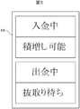
- the meaning and function of the status display unit 19 are as described above, but in other words, it functions as means for notifying the customer. As shown in FIG. 5, “Payment in progress” is displayed during the deposit process, and “Addition possible” is displayed if the banknotes can be stacked. Further, “withdrawing” is displayed during the withdrawal process, and “waiting for withdrawal” is displayed when the withdrawal is completed or when it is necessary to remove the bill once. Both are displayed according to instructions from the control unit 10.
- a liquid crystal display is used as the status display unit 19, but other display means may be used.
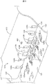
- FIG. 3 is a perspective view showing a roller configuration involved in bill feeding in the depositing unit 120
- FIG. 4 is a cross-sectional view showing a main roller configuration involved in bill feeding from the depositing unit 120 to the upstream depositing path 181.
- the depositing unit 120 has a configuration in which there is no shutter at the top, and has a configuration in which additional banknotes are easily stacked during the depositing process.
- the depositing unit 120 includes an opening recess 121 whose upper end is opened.
- the opening recess 121 deposits and holds the accepted banknote B on the inclined bottom wall, and surrounds the banknote B with the side wall 122 and the banknote end side wall 123 around the recess.
- the depositing unit 120 forms a delivery path part 124 by the lower end of the banknote end side wall 123 and the inclined bottom wall of the opening recess 121, and the delivery path part 124 serves as an upstream depositing path at the bottom corner. Connect to (not shown).
- the depositing unit 120 includes a plurality of banknote delivery first rollers 125, a banknote delivery second roller 126, and a banknote delivery third roller 127 on the inclined bottom wall of the opening recess 121. Each of these delivery rollers rotates with the roller peripheral wall protruding from the inclined bottom surface of the opening recess 121.
- a sensor 401 for detecting the amount (approximate number) of bills for example, an optical sensor, is installed on the bill end side wall 123. Strictly speaking, the sensor 401 does not directly detect the amount of banknotes (such as n banknotes) but detects the presence or absence of banknotes.
- the sensor 401 is installed at a predetermined height from the bottom surface (open recess 121 in the figure), that is, at a position (predetermined position) where n bills are deposited from the bottom surface. Therefore, when the sensor 401 detects the banknote, the control unit 10 determines that n or more banknotes are accumulated. The significance of the arrangement of the sensor 401 and its operation will be described later. Further, since the sensor 401 is included in the banknote deposit mechanism 12, it is not shown in FIG.
- a sensor (not shown) that detects the sending of banknotes from the depositing unit 120 is installed in the delivery path unit 124. When this sensor no longer detects banknotes, the control unit 10 can determine that all the banknotes deposited on the depositing unit 120 have disappeared.
- the depositing unit 120 rotationally drives each of the above-described delivery rollers in the direction of the arrow shown in FIG. 4, so that the banknotes B accumulated in the opening recesses 121 are extended from the banknotes B on the lower side of the stack to the delivery path unit 124. In this case, they are sent one by one to the upstream deposit path connected to this. Since the banknote sending first roller 125 has a radius of a part of the outer peripheral arc larger than the radius of the other arc portion, the banknote B that has been deposited in the opening recess 121 is moved up and down from the banknote B on the lower side of the stack. It sends out to the delivery path section 124.
- the depositing unit 120 is provided with a perfect circle-shaped banknote delivery first auxiliary roller 125 a along with the banknote delivery first roller 125.
- the depositing unit 120 includes an impeller 128 on the lower end side of the banknote end side wall 123. As shown in FIG. 6, a plurality of the impellers 128 are disposed on the banknote end side wall 123, and the tips of the blades 129 protrude from the opening 123 h of the banknote end side wall 123 into the opening recess 121. The blade 129 protruding in this way can be brought into contact with the bill B held in the opening recess 121.
- the impeller 128 is driven to rotate when the banknote B is sent out from the depositing unit 120 under the control of the control unit 10 to be described later, and the plurality of blades 129 that the blade wheel 129 has accumulated on the opening concave portion 121. In detail, it is made to contact the edge part side of the bill B.
- the impeller 128 since the impeller 128 is rotated in the direction of the arrow shown in FIG. 4, the blade 129 is placed on the end of the lower bill B accumulated in the opening recess 121, and the blade 129 is placed on the upper side of the bill accumulation. Hang it from the bottom to make contact.
- the banknotes B accumulated in the opening recess 121 are sequentially transferred one by one from the banknotes B on the lower side of the stack by rotation of the delivery rollers including the banknote delivery first roller 125 and end contact of the blades 129. It is sent to the sending path unit 124.
- sending banknotes there may be one banknote B received in the opening recess 121 or one banknote B at the top of the stacked banknotes may remain.
- the banknote B will be The stop posture may be taken while being in contact with the outer surface of the end side wall 123 and may remain in the opening recess 121.
- the depositing unit 120 brings the blade 129 into contact with the bill end of the bill B in such a stopped posture as described above, so that the bill B changes its posture from the stopped posture, and the bill end is the bottom of the opening recess 121. Pressed against the corner. As a result, the bill B that has not been in contact with the delivery roller because it has been in a stopped posture until then contacts either or both of the bill delivery first roller 125 and the bill delivery second roller 126.
- the sensor 401 sends out banknotes out of the wall surface extending in the depositing direction in the depositing unit 120 (feeding out). Provided on the side wall. By tilting the bottom surface (the opening recess 121) on which banknotes deposited on the depositing unit 120 are stacked in the delivery direction, it becomes easy to align the tips of a large number of banknotes. Therefore, the sensor 401 can accurately detect the amount of banknotes deposited on the depositing unit 120.
- the place where the sensor 401 is installed is not limited to the above example. For example, the amount of banknotes is detected even if the sensor 401 is installed on a wall surface (wall surface on the short side of the banknote) perpendicular to the direction in which the banknote B is sent out. can do.
- the sensor 401 is preferably at a position higher than the height of the tip of the blade 129 of the impeller 128 that sends out banknotes. That is, when the banknotes stacked in the depositing unit 120 are sent out by the control unit 10 while the blades 129 of the impeller 128 are sent out inside the apparatus, the customer is sending out the banknotes to be added. Will be stacked on the banknotes. At that time, if the customer's finger holding the additional banknote comes into contact with the blade 129, there is a risk that the banknote will be sent out.
- the height of the sensor 401 is set at a position higher than the height of the tip of the vane 129 of the root wheel 128, and the presence or absence of a banknote at that height is detected.
- the determination of whether or not additional bills can be stacked by the control unit 10 will be described.
- the sensor 401 detects the amount of banknotes stacked in the depositing unit 120, that is, whether the banknotes stacked in the depositing unit 120 have reached a predetermined height.
- the detection signal is transferred to the control unit 10.
- the control unit 10 can determine whether or not a predetermined amount (that is, a predetermined number) of banknotes is accumulated in the depositing unit 120, and based on the detection result of the banknotes of the sensor 401, It is possible to determine whether or not the stacking is possible.
- the control unit 10 determines that the banknotes are accumulated and “No”.
- the control unit 10 increases the number to “OK”. This makes it possible to increase the number of additional banknotes before the banknotes run out, while suppressing the number of times that the customer increases the banknotes (labor), and to increase the efficiency of the deposit process.
- the upper portion of the depositing unit 120 is not configured to have a shutter.
- the control unit 10 removes banknotes stacked on the depositing unit 120 from the apparatus. Control may be performed so that the shutter is closed during taking in, and the shutter is opened when additional banknotes are allowed to be stacked.
- two sensors are installed at different heights.
- the first sensor 401 is installed at a position higher than the tip of the blade 129 of the impeller 128 (the above example), and the second sensor 402 is installed at a position higher than that.
- the control unit 10 increases the banknotes “No”. Judge. In addition, when the second sensor detects that there is no banknote and the first sensor detects that there is a banknote, the first predetermined amount of banknotes is accumulated in the depositing unit 120. Since a fixed amount of banknotes has not been accumulated, the control unit 10 determines that the banknotes are stacked “OK”. When the first sensor detects that there are no banknotes, since the first predetermined amount of banknotes is not accumulated in the depositing unit 120, the control unit 10 determines that the banknotes are stacked “NO”.
- Example 1 Control operation for additional replenishment of banknotes in deposit processing (example 1)> With reference to FIG. 6, the control of the additional replenishment of the deposited banknote in the deposit process will be described.
- This example is based on the premise that one sensor 401 for detecting the amount of banknotes is installed in FIG. 3 or FIG.
- Each control operation is controlled by the control unit 10.
- the operation leading to this deposit processing is, for example, the customer selects ATM deposit, inserts a transaction card from the card entrance 150, inputs the customer's PIN from the numeric keypad 18, and the host computer It is assumed that the customer is authorized based on the personal identification number and that the customer is permitted to make a deposit transaction.
- the deposit process is started in a state where the bill B is stacked in the opening recess 121 of the deposit unit 120.
- the depositing process involves an operation of conveying the bill B from the depositing unit 120 to the inside and determining the denomination or authenticity of the bill at the discrimination unit.
- the status display unit 19 displays “Payment in progress”.
- the banknotes are sent one by one from the banknote B on the lower side of the stack sequentially by the rotation of the delivery rollers including the banknote delivery first roller 125 and the end contact of the blade 129. Is done.
- the stacking height of the bills B gradually decreases.
- the control unit 10 confirms whether the deposit process is in progress (S601).
- the confirmation during the depositing process is performed, for example, by a sensor (not shown) installed in the delivery path unit 124 detecting a bill fed out from the depositing unit 120 or installed in a conveyance path from the delivery path unit 124 to the banknote storage. This is performed depending on whether a sensor (not shown) detects the presence of a bill.
- a sensor not shown
- the state of the sensor 401 is confirmed (S602).
- the sensor 401 detects the banknote B (S602: YES)
- the control unit 10 confirms whether the sensor 401 detects the bill B in order to confirm whether the bill B is additionally replenished (S604). If the sensor 401 detects the banknote B as a result of the confirmation, it is determined that the banknote B has been additionally replenished, and the announcement of additional replenishment permission is terminated (S605). In this case, the operation is performed again as to whether the sensor 401 detects the banknote B (S602). As a result, if the sensor 401 does not detect the banknote B, the banknote detection operation by the sensor 401 is repeated until the deposit process is completed (S602 to S605).
- the control unit 10 determines whether the banknote is being deposited (S606). This determination is made based on, for example, whether or not a sensor (not shown) installed in the delivery path section 124 of the depositing section 120 or the banknote transport path detects the banknote. If the bill deposit process is not in progress (i.e., the deposit process is completed), the announcement of the additional bill refill permission is terminated (S607).
- Example 1 According to the control operation of Example 1, it is possible to effectively inform the customer that additional replenishment of banknotes is possible, and it is possible to shorten the transaction time and improve customer convenience. Further, by using the status display unit 9 to guide the possibility of additional replenishment of banknotes, it can be expected that the operability of customers will be improved.
- Example 2 does not use the above-described sensor 401 that detects the amount of banknotes in the depositing unit 120, but uses the information on the number of banknotes counted by the discrimination unit of the banknote depositing mechanism 12 to replenish banknotes in the depositing unit 120. To control. Note that the processing until the deposit transaction is permitted based on the password entered by the customer is the same as in Example 1.
- the bills are sent one by one from the banknote B on the lower side of the stack sequentially to the delivery path unit 124 by rotation of the banknote delivery first roller 125 and the end portion contact of the blade 129, and in the discrimination unit
- the number of banknotes is counted, and the denomination and authenticity of the banknotes are further determined.
- the number of banknotes counted by the discrimination unit is sequentially updated and temporarily stored in a memory included in the control unit 10.
- the control unit 10 determines whether the updated number of banknotes exceeds a predetermined value every time the number of banknotes is updated (S701).
- This predetermined value corresponds to the above-described predetermined amount for determining whether or not bills are stacked.
- the deposit process is continued (S702), and the process of S701 is repeated.
- an additional replenishment permission is announced (S703). This announcement is the same as in Example 1 above.
- the additional replenishment permission control can be performed by setting the number of deposited banknotes as a determination target.
- the state of the sensor 401 that is, whether the sensor 401 detects a banknote
- the state of the sensor 401 is confirmed. If the banknote is detected, it is determined that the banknote has been additionally replenished. Then, it may be controlled to end the announcement of additional replenishment permission.
- the payment process After accepting the deposit of the number of banknotes (hereinafter referred to as the “prescribed number”) that requires the determination of whether or not to continue the deposit, if the determination of whether or not to continue is performed, Including the time to prepare information necessary for authentication), the payment process will be stopped, and the transaction time will be prolonged.
- Example 3 the first specified number of sheets for requesting the customer to input information for determining whether or not to continue the deposit of banknotes, and the second number for determining interruption of the deposit that is larger than the first specified number of sheets.
- the deposit processing is executed using the two prescribed number of sheets.
- the first specified number of sheets and the second specified number of sheets are information on the total number of sheets that are sequentially updated, which are counted by the discrimination unit of the banknote deposit mechanism 12.
- the deposit process it is determined whether the number of deposited banknotes counted by the discrimination unit has exceeded the first specified number (S801).
- the process before that that is, the process until the deposit transaction is permitted based on the authentication information inputted by the customer, for example, the personal identification number, is the same as that in the first example.
- the control unit 10 guides the display unit of the customer operation unit 16 whether to perform a deposit transaction exceeding the second specified number.
- a screen is displayed (S802).
- the control unit 10 performs the processing after S804. If there is an input indicating that the process is not to be continued (S803: NO), the process proceeds to step S808.
- the control unit 10 When there is an input from the customer operation unit 16 or the numeric keypad mechanism 18 to continue the deposit transaction exceeding the second specified number (S803: YES), the control unit 10 causes the customer operation unit 16 to authenticate the customer. A guidance screen for inputting information is displayed (S804).
- the authentication information is information unique to the customer registered in advance in the storage unit of the host computer.
- the authentication information for example, the first used password, another password different from the password, or the fingerprint information or finger vein information of the customer's finger can be used.
- a reader for fingerprint information or finger vein information is installed in connection with the control unit 10.
- the control unit 10 transmits the authentication information to the host computer via the I / F unit 11. Then, the host computer determines whether the authentication information is valid for the customer (S805). That is, it is determined whether the current customer is a legitimate customer by collating the authentication information registered in the storage unit in advance with the authentication information received this time.
- the control unit 10 receives the result of the determination from the host computer, and if it is valid authentication information (S805: YES), the control unit 10 releases the restriction on the number of deposited banknotes (S806) and continues the depositing process (S807). . In other words, this allows the customer to additionally replenish banknotes in the depositing unit 120. As long as all sensors (not shown) installed in the transport path detect the presence of banknotes, the deposit process is continued (S808: FES). However, when all the sensors (not shown) installed in the conveyance path no longer detect the presence of the banknote (S808: NO), the control unit 10 determines that the depositing process is completed and ends the depositing process (S809). ).
- the control unit 10 determines whether the deposited banknote exceeds the second specified number (S810). As a result of the determination, if the second specified number is exceeded, the deposit process is stopped (S811). Thereafter, the process proceeds to step S805. As a result, the processing is repeated between steps S805 to S810 to S811, but in this case, the control unit 10 displays a screen including a “cancel button” on the customer operation unit 16 at an arbitrary timing. Then, by causing the customer to select the “cancel button”, it is possible to control to cancel the repetition of the process.
- a customer deposits 300 banknotes
- personal authentication that is, input of authentication information
- 100 sheets are set as the first specified number
- 200 sheets are set as the second specified number.
- the control unit 10 deposits 200 or more banknotes in parallel on the display unit of the customer operation unit 16 while continuing the depositing process up to 200 banknotes when the number of deposited banknotes exceeds 100. Displays a guidance screen indicating that personal authentication is required. In addition, it requests the input of authentication information necessary for personal authentication. If 200 or more sheets are to be processed, it is determined whether or not the deposit can be continued based on the authentication result of the authentication information received from the customer.
- This control makes it possible to determine whether or not to continue before processing 200 sheets. If the banknote deposit process is completed before processing 200 banknotes, the process can be continued without stopping. Further, even if the personal authentication process takes time, the deposit process for 200 sheets is completed, and the deposit process is temporarily stopped, it takes more than the individual process to be started after the deposit process is stopped. Time can be shortened.
- the control unit 10 exceeds the second specified number or has a deposit. May be displayed on the customer operation unit 16 and the customer may be asked for input for the confirmation.
- the control unit 10 may request the customer to input authentication information only when an input indicating that there is a deposit exceeding the second specified number is received from the customer. Thereby, it becomes possible to suppress the input of unnecessary authentication information from the customer.
- a mark (display) indicating the height when the second specified number of banknotes is stacked is displayed on the banknote of the deposit unit 120 It may be displayed on the end side wall 123.
- a mark indicating the height when the number of bills based on the difference between the second prescribed number and the first prescribed number may be accumulated may be displayed on the bill end side wall 123 in the same manner.
- Example 3 when personal authentication is required during the deposit process, an announcement may be made to request the customer during the deposit process using the detection signal of the sensor 401 described above. Specifically, when the sensor 401 detects the absence of banknotes during the deposit process, it may be displayed that personal authentication is necessary, that is, authentication information input guidance (S802).
Landscapes
- Physics & Mathematics (AREA)
- General Physics & Mathematics (AREA)
- Engineering & Computer Science (AREA)
- Mechanical Engineering (AREA)
- Financial Or Insurance-Related Operations Such As Payment And Settlement (AREA)
Abstract
多量の紙幣を連続的に入金処理することを可能とする。 入金部120に堆積された紙幣Bを順次、内部へ搬送する送出機構125~127、128、129と、入金部に堆積された紙幣を検知する、所定の位置に設置されたセンサ401と、入金処理中にあって、センサによる検知信号を用いて入金部に紙幣の追加補充を判断する制御部10と、制御部の判断に応じて利用者へ紙幣の追加補充を通知する通知手段19と、を有し、入金部に堆積された紙幣を内部に取り込んで入金処理する。
Description
本発明は、紙幣取扱装置に係り、特に大量の紙幣を取り扱うことができる紙幣の入金処理に関するものである。
現金自動取引装置(ATM)で大量の紙幣を入金または出金したいという要求が増大している。この要求に応えるため、例えば、特許文献1には、1回の取引における支払限度額を超える金額の取引を可能とするために、1回の取引操作で紙幣の出金、受取を複数回連続して行い、その計数状況を表示部に表示する自動取引が開示されている。例えば、250万円の出金する場合、100万円、100万円、50万円と、3回に分けて出金する旨を案内画面に表示し、更に現在何れに段階が処理中かを示すグラフをブリンンク表示することで、利用者に取引の進捗状況を知らせる、としている。
特許文献1には、多量の金額を出金する場合の処理について記載されているが、多量の紙幣を入金する場合の機構や処理については示唆がない。多量の紙幣を入金する場合、入金口に1回にセットできる紙幣の枚数には限度があるので、紙幣を何回かに分けて入金口に紙幣を追加的にセットすることになる。その場合、連続する紙幣のセットのための時間を出来るだけ短縮させて、取引時間の短縮化を図ることが望ましい。
本発明の目的は、多量の紙幣を連続的に入金処理することが可能な紙幣取扱装置を提供することにある。
本発明の好ましい例による紙幣取扱装置は、入金部に堆積された紙幣を内部に取り込んで入金処理する紙幣取扱装置であって、
該入金部に堆積された紙幣を順次、内部へ搬送する送出機構と、
該入金部に堆積された紙幣を検知する、所定の位置に設置されたセンサと、
入金処理中にあって、該センサによる検知信号を用いて該入金部に紙幣の追加補充を判断する制御部と、
該制御部の判断に応じて利用者へ紙幣の追加補充を通知する通知手段と、を有する紙幣取扱装置として構成される。
該入金部に堆積された紙幣を順次、内部へ搬送する送出機構と、
該入金部に堆積された紙幣を検知する、所定の位置に設置されたセンサと、
入金処理中にあって、該センサによる検知信号を用いて該入金部に紙幣の追加補充を判断する制御部と、
該制御部の判断に応じて利用者へ紙幣の追加補充を通知する通知手段と、を有する紙幣取扱装置として構成される。
本発明の他の好ましい例による紙幣取扱装置は、入金部に堆積された紙幣を内部に取り込んで入金処理する紙幣取扱装置であって、
該入金部に堆積された紙幣を順次、内部へ搬送する送出機構と、
該送出機構により送られる紙幣を計数する計数手段と、
該計数手段によって計数される紙幣の枚数が所定値を超えたかを判断する制御部と、
入金処理中にあって、該制御部が所定値を超えたと判断したとき、該制御部からの指示により利用者へ紙幣の追加補充を通知する通知手段と、を有する紙幣取扱装置として構成される。
該入金部に堆積された紙幣を順次、内部へ搬送する送出機構と、
該送出機構により送られる紙幣を計数する計数手段と、
該計数手段によって計数される紙幣の枚数が所定値を超えたかを判断する制御部と、
入金処理中にあって、該制御部が所定値を超えたと判断したとき、該制御部からの指示により利用者へ紙幣の追加補充を通知する通知手段と、を有する紙幣取扱装置として構成される。
本発明によれば、多量の入金紙幣がある場合、入金口に逐次積み増された紙幣を順次内部に繰り込むことができ、入金取引の時間を長引かせることなく、多量の紙幣を入金処理することが可能である。
以下、図面を参照して本発明の実施形態について詳述する。
<紙幣取扱装置の全体構成>
図1は、紙幣の入出金を行う紙幣取扱装置の外観を示す。紙幣取扱装置において、入金部120は紙幣入金機構12の一部であり、入金される紙幣がここにセットされる。入金処理の場合、入金部120に紙幣が堆積してセットされ、下方に位置する紙幣から順に一枚ずつ内部へ取り込まれる。出金部140は紙幣出金機構14の一部であり、装置の内部より1枚ずつ繰り出される紙幣がここに集積される。なお、入金部と出金部とは別々の機構でなく、機構的に共通する1つの部位としてもよい。
図1は、紙幣の入出金を行う紙幣取扱装置の外観を示す。紙幣取扱装置において、入金部120は紙幣入金機構12の一部であり、入金される紙幣がここにセットされる。入金処理の場合、入金部120に紙幣が堆積してセットされ、下方に位置する紙幣から順に一枚ずつ内部へ取り込まれる。出金部140は紙幣出金機構14の一部であり、装置の内部より1枚ずつ繰り出される紙幣がここに集積される。なお、入金部と出金部とは別々の機構でなく、機構的に共通する1つの部位としてもよい。
カード出入口150は、利用者が所持する取引カード(例えばICカード)を挿入又は排出する部位であり、その内部には取引カードに記録された情報を読み取るカード読取機構15を備えている。
顧客操作部16は例えば液晶タッチパネルであり、入金や出金等のための取引画面を表示する表示部と顧客の操作により入力できる入力部を備える。明細票口170は入金や出金の取引結果を印字した明細票を出力する部位であり、その内部には明細票に取引結果を印字する明細票発行機構17を備えている。テンキー機構18は、顧客が暗証番号や金額を入力する数字キーから成る入力部である。状態表示部19は装置の動作状況や取引状況を表示する例えば液晶表示器である。状態表示部19には図5に示すような装置の状況や顧客への指示が表示される。
顧客操作部16が表示部を備えているので、本来的には装置の動作や取引状況を顧客操作部16に表示することが可能であるが、あえて状態表示部19を入金部120及び出金部140の近くに設けたのは、大量の紙幣を連続的に入金する場合、顧客に安心感を与え、操作性の向上を図るためである。即ち、入金や出金操作の手元と動作確認のための表示を余り離さないで、入金部120や出金部140と同じ操作面(水平面)上にあってそれらの近傍に配置することで、顧客が入金又は出金する紙幣からあまり目を離すことなく、状態表示部19に表示される入金処理中又は出金処理中等の状態表示や、現在の入金枚数や出金枚数等の状況確認表示を容易に確認することができ、入力操作が必要な場合にはテンキー機構18より入力することが可能である。これにより、顧客は視線をあまり動かすことなく入金取引の動作を速めることができる。
図2は、紙幣取扱装置の制御構成のブロック図を示す。
制御部10は上記各部(各機構を含む)を制御する部位であり、主にプログラムを実行するCPUと、プログラムや取引に伴う種々のデータを記憶するメモリを有して構成される。顧客操作部16は制御部10からの指示に基づく取引情報を表示部に表示するとともに、入力部から入力される取引情報を制御部10へ送る。インタフェース(I/F)部11は、ネットワークを介して、制御部10をホストコンピュータ等の上位装置に接続して、上位装置との間で取引に関する情報を送受信する。カード読取機構15は、顧客のカードを読み込み、取引カードの情報およびエンボスの画像を取得する。
制御部10は上記各部(各機構を含む)を制御する部位であり、主にプログラムを実行するCPUと、プログラムや取引に伴う種々のデータを記憶するメモリを有して構成される。顧客操作部16は制御部10からの指示に基づく取引情報を表示部に表示するとともに、入力部から入力される取引情報を制御部10へ送る。インタフェース(I/F)部11は、ネットワークを介して、制御部10をホストコンピュータ等の上位装置に接続して、上位装置との間で取引に関する情報を送受信する。カード読取機構15は、顧客のカードを読み込み、取引カードの情報およびエンボスの画像を取得する。
紙幣入金機構12は、紙幣の枚数を計数し、金種や真偽の判定を行う鑑別部を有する。入金部120より搬送される紙幣はこの鑑別部で計数、鑑別されて、装置内部に備えられた収納庫に収納される(入金処理)。紙幣出金機構13は、出金する紙幣を鑑別部で計数して出金部130へ繰り出す(出金処理)。明細票発行機構17は、取引に関する情報を明細票に印字して、明細票口170より送出する。テンキー機構18は顧客の暗証番号や金額などの入力に用いられる。
状態表示部19の意義や機能は上述の通りであるが、別の言い方をすれば、顧客への通知手段として機能する。図5に示すように、入金処理中は「入金中」が表示され、紙幣の積み増しが可能な状態であれば「積増し可能」が表示される。また、出金処理中は「出金中」を表示し、出金が終了した場合または一度紙幣を抜取る必要がある場合は「抜取り待ち」を表示する。いずれも制御部10からの指示により表示される。
なお、上記の例では状態表示部19として液晶表示器を用いるとしたが、他の表示手段を用いてもよい。例えば、図5の表示項目を表面に予め用意しておき、表示項目対応にLEDを設けて、該当する表示項目のLEDを点灯するように制御することも可能である。また、他の例として、入金した紙幣の枚数を液晶表示器である状態表示部19に数字表示、又はインジケータ表示することも可能である。また、状態表示部19の表示に合わせてスピーカ(不図示)から、図5と同様の音声案内をすることも可能である。
<紙幣入金機構12の詳細な構造>
次に、図3及び図4を参照して、紙幣入金機構12の詳細な構成について説明する。
図3は入金部120において紙幣送出に関与するローラ構成を示す斜視図、図4は入金部120から上流側入金経路181への紙幣送出に関与する主要なローラ構成を示す断面図である。
次に、図3及び図4を参照して、紙幣入金機構12の詳細な構成について説明する。
図3は入金部120において紙幣送出に関与するローラ構成を示す斜視図、図4は入金部120から上流側入金経路181への紙幣送出に関与する主要なローラ構成を示す断面図である。
図示のように、入金部120は、上部にシャッタがない構成となっており、入金処理中に追加の紙幣を積み増し易い構成となっている。入金部120は、上端側が開放された開口凹部121を備える。開口凹部121は、受け付けた紙幣Bを傾斜底面壁に堆積して保持し、凹部周囲の側壁122と紙幣端部側壁123とで紙幣Bを取り囲む。また、入金部120は、紙幣端部側壁123の下端と開口凹部121の傾斜底面壁とで送出経路部124を構成し、この送出経路部124で開口凹部121をその底部コーナーにおいて上流側入金経路(図示省略)に接続する。入金部120は、開口凹部121の傾斜底面壁に、紙幣送出第1ローラ125と、紙幣送出第2ローラ126と、紙幣送出第3ローラ127をそれぞれ複数備える。これら各送出ローラは、開口凹部121の傾斜底面からローラ周壁を突出させて、それぞれ回転する。
紙幣端部側壁123には、紙幣の量(おおよその枚数)を検知するセンサ401、例えば光学センサが設置される。厳密に言えば、センサ401は、紙幣の量(紙幣n枚の如き)を直接に検知するわけではなく紙幣の有無を検知する。センサ401は底面(図示の開口凹部121)から所定の高さ、即ち底面からn枚の紙幣が堆積される位置(所定の位置)に設置される。従って、センサ401が紙幣を検知しているときには、制御部10は紙幣がn枚以上堆積していると判断する。なお、センサ401の配置の意義やその作用については後述する。またセンサ401は紙幣入金機構12に含まれるため、図2には図示していない。
なお、図示していないが、送出経路部124には、入金部120からの紙幣の送出を検知するセンサ(不図示)が設置される。このセンサが紙幣を検知しなくなると、制御部10は入金部120に堆積した紙幣が全て無くなったと判断できる。
入金部120は、上記の各送出ローラを、図4に示す図中矢印方向に回転駆動して、開口凹部121に堆積済みの紙幣Bを、堆積下方側の紙幣Bから送出経路部124、延いてはこれに接続する上流側入金経路に一枚ずつ送り出す。紙幣送出第1ローラ125は、一部外周円弧の半径を他の円弧箇所の半径より大きくしているので、開口凹部121に堆積済みの紙幣Bを、上下動させつつ堆積下方側の紙幣Bから送出経路部124に送り出す。なお、入金部120は、紙幣送出第1ローラ125に並んで、真円状の紙幣送出第1補助ローラ125aを備える。
この他、入金部120は、紙幣端部側壁123の下端側に、羽根車128を備える。この羽根車128は、図6に示すように、紙幣端部側壁123において複数配設され、紙幣端部側壁123の開口123hから、羽根129の先端を開口凹部121の内部に突出させている。こうして突出した羽根129は、開口凹部121に保持された紙幣Bに対して接触可能とされている。この羽根車128は、後述の制御部10の制御を受けて、入金部120からの紙幣Bの送り出しに際して回転駆動し、その有する複数の羽根129を、開口凹部121で堆積した下方側の紙幣B、詳しくは紙幣Bの端部側に接触させる。
本実施例では、羽根車128を図4に示す図中矢印方向に回転させるので、羽根129は、開口凹部121で堆積した下方側の紙幣Bの端部に、羽根129を紙幣堆積の上方側から下方側に掛けて接触させる。このため、開口凹部121で堆積した紙幣Bは、紙幣送出第1ローラ125を始めとする送出ローラの回転と、羽根129の端部接触により、堆積下方側の紙幣Bから一枚ずつ、順次、送出経路部124に送出される。紙幣送出にあたり、開口凹部121で受け入れた紙幣Bが一枚であったり、堆積紙幣の最上部の紙幣Bが一枚残ることが有り得る。こうした一枚の紙幣Bが或いは数枚程度の紙幣Bが図示するように、仮に屈曲して上記の第1、第2の紙幣送出ローラと非接触となると、この紙幣Bは、紙幣先端を紙幣端部側壁123の外表面に接触させたまま停止姿勢を取り、開口凹部121に留まることがあり得る。入金部120は、こうした停止姿勢にある紙幣Bの紙幣端部に羽根129を上記したように接触させるので、紙幣Bは停止姿勢からその姿勢を変化させて、紙幣端部は開口凹部121の底部コーナーの側に押し付けられる。これにより、それまで停止姿勢にあったために送出ローラと非接触であった紙幣Bは、紙幣送出第1ローラ125と紙幣送出第2ローラ126のいずれか、或いは両者に接触する。
センサ401の設置場所及び設置高さの意義について説明する。
入金部120に堆積される紙幣の量を精度よく検知するため、図示の例では、センサ401は、入金部120における紙幣が堆積される方向に延伸する壁面のうち、紙幣が送出される(繰出される)側の壁面に設けた。入金部120に堆積される紙幣を積み置く底面(上記開口凹部121)を、その送出方向へ傾斜させることで、多数の紙幣の先端を揃えることが容易となる。そのため、センサ401により、入金部120に堆積された紙幣の量をセンサ401により精度よく検知できる。なお、センサ401を設置する場所については上記の例に限定されず、例えば、紙幣Bが送出される方向と直角な壁面(紙幣の短幅側の壁面)に設置しても紙幣の量を検知することができる。
入金部120に堆積される紙幣の量を精度よく検知するため、図示の例では、センサ401は、入金部120における紙幣が堆積される方向に延伸する壁面のうち、紙幣が送出される(繰出される)側の壁面に設けた。入金部120に堆積される紙幣を積み置く底面(上記開口凹部121)を、その送出方向へ傾斜させることで、多数の紙幣の先端を揃えることが容易となる。そのため、センサ401により、入金部120に堆積された紙幣の量をセンサ401により精度よく検知できる。なお、センサ401を設置する場所については上記の例に限定されず、例えば、紙幣Bが送出される方向と直角な壁面(紙幣の短幅側の壁面)に設置しても紙幣の量を検知することができる。
センサ401の設置高さについて言えば、センサ401は、紙幣を送出する羽根車128の羽根129の先端の高さよりも高い位置が好ましい。即ち、入金部120に積まれた紙幣を、羽根車128の羽根129が装置内部に送出中に、制御部10より追加の紙幣の積み増し許可があった場合、顧客は追加すべき紙幣を送出中の紙幣の上に積むことになる。そのとき、追加の紙幣を掴んだ顧客の指が羽根129に接触すると、紙幣の送出に支障が生じる恐れがある。そこで、センサ401の高さを根車128の羽根129の先端の高さよりも高い位置に設置しておき、その高さでの紙幣の有無を検知して、紙幣無しの場合に制御部10が追加紙幣の積み増し「可」とすることで、顧客の指が羽根129に接触することを防止することができる。
制御部10による追加紙幣の積み増しの可否の判断について述べる。
センサ401は、入金部120に積まれる紙幣の量、即ち入金部120に積まれた紙幣が所定の高さに達してしているかを検知する。所定の高さに設置されたセンサ401が紙幣を検知したら、その検知信号が制御部10へ転送される。これにより制御部10は、入金部120に所定量(即ち所定枚数)の紙幣が堆積されているか否かを判断することが可能となり、センサ401の紙幣有無の検知結果に基づき、追加の紙幣の積み増しの可否を判断することができる。
センサ401は、入金部120に積まれる紙幣の量、即ち入金部120に積まれた紙幣が所定の高さに達してしているかを検知する。所定の高さに設置されたセンサ401が紙幣を検知したら、その検知信号が制御部10へ転送される。これにより制御部10は、入金部120に所定量(即ち所定枚数)の紙幣が堆積されているか否かを判断することが可能となり、センサ401の紙幣有無の検知結果に基づき、追加の紙幣の積み増しの可否を判断することができる。
例えば、センサ401が紙幣有りを検知した場合、入金部120には所定量(所定高さ)の紙幣が堆積しているので、制御部10は紙幣積み増し「否」とする。一方、センサ401が紙幣無しを検知している場合、入金部120には所定量の紙幣が堆積されていないので、制御部10は積み増し「可」とする。これにより、顧客による紙幣積み増しの回数(手間)を抑制しつつ、紙幣が無くなる前に追加紙幣の積み増しが可能となり、入金処理の効率を高めることが可能となる。
なお、図示の例では、入金部120の上部にシャッタを持たない構成としたが、シャッタを有している紙幣取扱装置の場合、制御部10は、入金部120に積まれた紙幣を装置の内部に取り込む最中はシャッタを閉じるように制御し、追加の紙幣の積み増しを許可するときにシャッタを開くように制御してもよい。
<センサ401の設置の他の例>
この例は、2つのセンサを高さの異なる位置に設置した例である。例えば、羽根車128の羽根129の先端の高さよりも高い位置に第1のセンサ401を設置し(上記の例)、更にそれよりも高い位置に第2のセンサ402を設置する。
この例は、2つのセンサを高さの異なる位置に設置した例である。例えば、羽根車128の羽根129の先端の高さよりも高い位置に第1のセンサ401を設置し(上記の例)、更にそれよりも高い位置に第2のセンサ402を設置する。
第2のセンサが紙幣有りを検知している場合、入金部120には第2の所定量の紙幣(十分な量の紙幣)が堆積しているので、制御部10は紙幣の積み増し「否」と判断する。また、第2のセンサが紙幣無しを検知しかつ第1のセンサが紙幣有りを検知している場合、入金部120には第1の所定量の紙幣は堆積しているが、第2の所定量の紙幣が堆積していないので、制御部10は、紙幣の積み増し「可」と判断する。また、第1のセンサが紙幣無しを検知している場合、入金部120には第1の所定量の紙幣が堆積していないので、制御部10は、紙幣の積み増し「否」と判断する。これにより、顧客による追加の紙幣積み増しの手間(過剰な回数の積み増し)を抑制し、紙幣が無くなる前に追加紙幣の積み増しが可能となる。また、顧客の手が羽根車128のような紙幣送出ローラに接触するのを防止できる。
<入金処理における紙幣の追加補充の制御動作(例1)>
図6を参照して、入金処理における入金紙幣の追加補充の制御について説明する。
この例は、図3又は図4において、紙幣の量を検知する1つのセンサ401が設置されていることを前提とする。また、各制御動作は制御部10の制御による。この入金処理に至る動作は、周知のように、顧客が例えばATMの入金を選択し、取引カードをカード出入り口150から挿入し、テンキー機構18から顧客の暗証番号を入力して、ホストコンピュータが当該暗証番号を基に正当な顧客である旨の判断を行って、当該顧客に入金取引が許可されたことを前提としている。
図6を参照して、入金処理における入金紙幣の追加補充の制御について説明する。
この例は、図3又は図4において、紙幣の量を検知する1つのセンサ401が設置されていることを前提とする。また、各制御動作は制御部10の制御による。この入金処理に至る動作は、周知のように、顧客が例えばATMの入金を選択し、取引カードをカード出入り口150から挿入し、テンキー機構18から顧客の暗証番号を入力して、ホストコンピュータが当該暗証番号を基に正当な顧客である旨の判断を行って、当該顧客に入金取引が許可されたことを前提としている。
紙幣Bが入金部120の開口凹部121に積み上げられた状態で入金処理を開始する。ここで入金処理とは、入金部120から紙幣Bを内部に搬送して鑑別部で紙幣の金種や真偽の判定を行う動作を伴う。以下の例2及び例3でも同様である。このとき、状態表示部19は「入金中」が表示している。入金処理が開始されると、紙幣送出第1ローラ125を始めとする送出ローラの回転と、羽根129の端部接触により、堆積下方側の紙幣Bから一枚ずつ順次、送出経路部124に送出される。紙幣Bの積み上げ高さは徐々に低くなる。この時、制御部10は入金処理中であるかを確認する(S601)。入金処理中の確認は、例えば送出経路部124に設置されたセンサ(不図示)が入金部120から繰り出される紙幣を検知しているか、送出経路部124から紙幣の収納庫に至る搬送路に設置されたセンサ(不図示)が紙幣の存在を検知しているか、により行われる。確認の結果、入金処理中であることが分かると、センサ401の状態を確認する(S602)。この確認の結果、センサ401が紙幣Bを検知していたら(S602:YES)、センサ401が紙幣Bを検知し無くなるまで待機する。センサ401が紙幣の無くなったことを検知したら(S602:NO)、紙幣の追加補充が可能である旨(追加補充許可)をアナウンスする(S603)。このアナウンスは、制御部10が状態表示部19を「積み増し可能」に表示することで行われる。なお、スピーカにより同様の音声案内をしてもよい。
制御部10は、紙幣Bが追加補充されたかを確認するため、センサ401が紙幣Bを検知しているかを確認する(S604)。この確認の結果、センサ401が紙幣Bを検知したら、紙幣Bが追加補充されたと判断して、追加補充許可のアナウンスを終了する(S605)。この場合、再びセンサ401が紙幣Bを検知しているかの動作を行う(S602)。その結果、センサ401が紙幣Bを検知していないと、入金処理が終わるまでセンサ401による紙幣の検知動作を繰り返す(S602~S605)。一方、センサ401が紙幣を検知していない場合(S604:NO)、制御部10は紙幣の入金処理中かを判断する(S606)。この判断は、例えば、入金部120の送出経路部124や紙幣の搬送路に設置されたセンサ(不図示)が紙幣を検知しているか否かに基づいて行われる。紙幣の入金処理中でない(即ち入金処理が終わった)場合、紙幣の追加補充許可のアナウンスを終了する(S607)。
例1の制御動作によれば、紙幣の追加補充が可能である旨を効果的に顧客に伝えることができ、取引時間の短縮や顧客の利便性を向上させることができる。また、状態表示部9を用いて紙幣の追加補充可能を案内することにより、顧客の操作性の一掃の向上が期待できる。
<入金処理における紙幣の追加補充の制御動作(例2)>
図7を参照して、入金処理における入金紙幣の追加補充の制御について説明する。
例2は、入金部120における紙幣の量を検知する上記したセンサ401を用いず、紙幣入金機構12が持つ鑑別部が計数する紙幣の枚数の情報を用いて、入金部120における紙幣の追加補充を制御する。なお、顧客により入力される暗証番号を基に入金取引が許可されるまでの処理は例1と同様である。
図7を参照して、入金処理における入金紙幣の追加補充の制御について説明する。
例2は、入金部120における紙幣の量を検知する上記したセンサ401を用いず、紙幣入金機構12が持つ鑑別部が計数する紙幣の枚数の情報を用いて、入金部120における紙幣の追加補充を制御する。なお、顧客により入力される暗証番号を基に入金取引が許可されるまでの処理は例1と同様である。
入金処理が開始されると、紙幣送出第1ローラ125等の回転と、羽根129の端部接触により、堆積下方側の紙幣Bから一枚ずつ順次、送出経路部124に送出され、鑑別部で紙幣の枚数が計数され、さらに紙幣の金種や真偽が判定される。鑑別部で計数される紙幣の枚数は順次更新されて、制御部10が有するメモリに一時記憶される。
制御部10は、紙幣の枚数が更新される度に、更新した紙幣の枚数が、予め定めた所定値を超えたかを判定する(S701)。この所定値は、紙幣の積み増しを判断する、上記した所定量に対応する。この判定の結果、更新した紙幣の枚数が所定値を超えていない場合、入金処理が継続しているかを確認して(S702)、S701の処理を繰り返す。一方、更新した紙幣の枚数が所定値を超えている場合、追加補充許可をアナウンスする(S703)。このアナウンスは上記例1と同様である。そして、紙幣の入金処理中かを確認して(S704)、入金処理が終わったら、追加補充許可のアナウンスを終了する(S705)。
例2によれば、センサ401を用いなくても、入金紙幣の枚数を判断の対象とすることで、追加補充許可の制御を行うことができる。ただし、センサ401が無いため、どれ程の紙幣が入金部120に積まれているのか、また、アナウンス後にどれ程の紙幣が積み増しされたのかが分からない。そこで、上記センサ401と組み合わせて、S703のアナウンス後にセンサ401の状態(即ちセンサ401が紙幣を検知しているか)を確認し、紙幣を検知しているならば、紙幣が追加補充されたと判断して、追加補充許可のアナウンスを終了するように制御してもよい。
<入金処理における紙幣の追加補充の制御動作(例3)>
図8を参照して、入金処理における入金紙幣の追加補充の制御について説明する。
入金金額が非常に大きい場合、顧客は入金紙幣を何回かに分けて入金部に追加補充する必要がある。この場合、顧客による入金の継続可否を確認し、かつ継続のときは顧客の認証情報を入力させることで安全に入金処理を継続させることができる。然るに、入金の継続可否の判断を必要とする紙幣の枚数(以下、規定枚数という)の入金を受け付けた後に、継続可否の判断を行うと、継続可否の判断をしている間(顧客が個人認証に必要となる情報を準備する時間も含む)、入金処理を止めてしまうこととなり、取引時間が長引くことになる。
図8を参照して、入金処理における入金紙幣の追加補充の制御について説明する。
入金金額が非常に大きい場合、顧客は入金紙幣を何回かに分けて入金部に追加補充する必要がある。この場合、顧客による入金の継続可否を確認し、かつ継続のときは顧客の認証情報を入力させることで安全に入金処理を継続させることができる。然るに、入金の継続可否の判断を必要とする紙幣の枚数(以下、規定枚数という)の入金を受け付けた後に、継続可否の判断を行うと、継続可否の判断をしている間(顧客が個人認証に必要となる情報を準備する時間も含む)、入金処理を止めてしまうこととなり、取引時間が長引くことになる。
そこで、例3では、紙幣の入金の継続可否を判断する情報の入力を顧客に要求する第一の規定枚数と、第一の規定枚数よりも多い枚数であって入金の中断を判断する第二の規定枚数との、2つの規定枚数を用いて入金処理を実行する。第一の規定枚数及び第二の規定枚数は、紙幣入金機構12が持つ鑑別部が計数する紙幣の逐次更新される合計枚数の情報である。
具体的には、入金処理において、鑑別部が計数する入金紙幣の枚数が第一の規定枚数を超えたかを判断する(S801)。なお、それ以前の処理、即ち顧客により入力される認証情報、例えば暗証番号を基に入金取引が許可されるまでの処理は例1と同様である。
上記判断の結果、入金紙幣の枚数が第一の規定枚数を超えた場合、制御部10は、顧客操作部16の表示部に、第二の規定枚数を超えた入金取引を実施するかの案内画面を表示する(S802)。この案内画面に従い、顧客操作部16又はテンキー機構18から、第二の規定枚数を超えた入金取引を継続する旨の入力があった場合(S803:YES)、制御部10はS804以降の処理を実行し、継続しない旨の入力があった場合(S803:NO)、ステップS808の処理に移る。
顧客操作部16又はテンキー機構18から、第二の規定枚数を超えた入金取引を継続する旨の入力があった場合(S803:YES)、制御部10は、顧客操作部16に、顧客の認証情報を入力する旨の案内画面を表示する(S804)。ここで、認証情報とは、予めホストコンピュータの記憶部に登録された顧客に固有の情報である。認証情報は、例えば、最初に用いた暗証番号や、当該暗証番号とは異なる別の暗証番号、更には顧客の指の指紋情報や指静脈情報を用いることができる。もちろん、後者の情報を入力するために、指紋情報や指静脈情報の読取器が制御部10に接続して設置される。
認証情報が入力されると、制御部10はその認証情報をI/F部11を介して、ホストコンピュータへ送信する。そしてホストコンピュータでは、その認証情報が当該顧客に正当な認証情報であるかを判断する(S805)。すなわち、予め記憶部に登録された認証情報と、今回受信した認証情報を照合することにより、今回の顧客が正当な顧客かを判断する。
制御部10は、ホストコンピュータから判断の結果を受信し、正当な認証情報である場合には(S805:YES)、入金紙幣枚数の制限を解除し(S806)、入金処理を継続させる(S807)。すなわち、これにより顧客は、入金部120に紙幣を追加補充することができる。搬送路に設置した全てのセンサ(不図示)が紙幣の存在を検知している限り、入金処理が継続して行われる(S808:FES)。しかし、搬送路に設置した全てのセンサ(不図示)が紙幣の存在を検知しなくなったとき(S808:NO)、制御部10は入金処理が終わったと判断して、入金処理を終了する(S809)。
先の判断で認証情報が正当でなかった場合(S805:NO)、制御部10は、入金紙幣が第二の規定枚数を超えたかを判断する(S810)。その判断の結果、第二の規定枚数を超えていれば、入金処理を停止する(S811)。その後、ステップS805に移行する。なお、この結果、ステップS805~S810乃至S811の間で処理が繰り返されることになるが、その場合には制御部10は任意のタイミングで顧客操作部16に「取消ボタン」を含む画面を表示して、顧客に「取消ボタン」を選択させることで、処理の繰り返しを解除するように制御することができる。
例えば、顧客が300枚の紙幣を入金する場合、200枚以上の取引の場合には個人認証(即ち認証情報の入力)が要求される例について説明する。ここで、100枚を第一の規定枚数とし、200枚を第二の規定枚数をする。制御部10は、入金紙幣の枚数が100枚を超えたときに200枚の紙幣までは入金処理を継続しながら、並行して顧客操作部16の表示部に200枚以上の紙幣を入金する場合は個人認証が必要な旨の案内画面を表示する。併せて、個人認証に必要な認証情報の入力を要求する。そして、200枚以上処理するのなら、顧客から受け付けた認証情報の認証結果に基づき、入金継続可否の判断をする。この制御により、200枚処理する前に継続可否の判断が可能になる。200枚の紙幣を処理する前に紙幣の入金処理が終わった場合、処理を止めることなく継続することが可能になる。また、仮に個人認証の処理に時間がかかり、200枚の入金処理が終わり、一時的に入金処理が停止したとしても、この入金処理が停止してから個人認証を始めるよりは、全体的にかかる時間を短縮することができる。
また、紙幣入金機構12が第一の規定枚数の紙幣を処理し、制御部10が認証情報の入力を顧客に要求する際に、制御部10は第二の規定枚数を超えるか入金があるかの確認を顧客操作部16に表示して、顧客にその確認のための入力を求めてもよい。顧客から、第二規定枚数を超える入金がある旨の入力を受け付けた場合にのみ、制御部10は、顧客に認証情報の入力を要求するようにしてもよい。これにより、顧客から不要な認証情報の入力を抑制することが可能となる。
また、第二の規定枚数を超えるか否かの判断を容易にできるようにするために、第二の規定枚数の紙幣を堆積した場合の高さを示す目印(表示)を入金部120の紙幣端部側壁123に表示してもよい。顧客が紙幣を入金部120に堆積したときに、認証情報の要否を予想することが可能となる。さらに第二の規定枚数と、第一の規定枚数の差分に基づく枚数の紙幣を堆積した場合の高さを示す目印を、同様にして紙幣端部側壁123に表示してもよい。制御部10が顧客による認証情報の入力を要求する旨を顧客操作部16に表示した時に、顧客は上記目印を基に認証情報の要否を予想することが可能となる。
更に、例3の変形例として、入金処理中に個人認証が必要な場合、上記のセンサ401の検知信号を用いて、入金処理の途中で顧客に対応を求めるアナウンスを行ってもよい。具体的には、入金処理中にセンサ401が紙幣無しを検知したときに、個人認証が必要な旨即ち認証情報の入力案内を表示する(S802)ようにしても良い。
10:制御部 11:I/F部
12:紙幣入金機構 120:入金部 14:紙幣出金機構 140:出金部
15:カード読取機構 150:カード出入口 16:顧客操作部
17:明細票発行機構 170:明細票口 18:テンキー機構
19:状態表示部
401:センサ
12:紙幣入金機構 120:入金部 14:紙幣出金機構 140:出金部
15:カード読取機構 150:カード出入口 16:顧客操作部
17:明細票発行機構 170:明細票口 18:テンキー機構
19:状態表示部
401:センサ
Claims (10)
- 入金部に堆積された紙幣を内部に取り込んで入金処理する紙幣取扱装置であって、
該入金部に堆積された紙幣を順次、内部へ搬送する送出機構と、
該入金部に堆積された紙幣を検知する、所定の位置に設置されたセンサと、
入金処理中にあって、該センサによる検知信号を用いて該入金部に紙幣の追加補充を判断する制御部と、
該制御部の判断に応じて利用者へ紙幣の追加補充を通知する通知手段と、
を有する紙幣取扱装置。 - 前記センサが紙幣を検知しなくなり、かつ該入金部に堆積された紙幣が無くなる前に、該制御部は、該入金部への紙幣の追加補充と判断する、
ことを特徴とする請求項1に記載の紙幣取扱装置。 - 入金部に堆積された紙幣を内部に取り込んで入金処理する紙幣取扱装置であって、
該入金部に堆積された紙幣を順次、内部へ搬送する送出機構と、
該送出機構により送られる紙幣を計数する計数手段と、
該計数手段によって計数される紙幣の枚数が所定値を超えたかを判断する制御部と、
入金処理中にあって、該制御部が所定値を超えたと判断したとき、該制御部からの指示により利用者へ紙幣の追加補充を通知する通知手段と、
を有する紙幣取扱装置。 - 利用者による入力を受ける操作部を有し、
前記制御部は、前記計数手段が前記所定値(第1の所定値)を計数したことを把握することができ、
該計数手段の計数値が該第1の所定値を超えたと判断した場合、該操作部から利用者の認証のための入力を許容する
ことを特徴とする請求項3に記載の紙幣取扱装置。 - 前記通知手段は表示部であり、
該表示部は、前記入金部が設置された位置と同じ面であって前記入金部の付近に設置される、
ことを特徴とする請求項1に記載の紙幣取扱装置。 - 前記センサは、前記入金部において堆積する紙幣の前端が接触する壁面にあって、所定の量の紙幣が残存する高さに設置される、
ことを特徴とする請求項1に記載の紙幣取扱装置。 - 前記送出機構は、前記入金部に堆積した紙幣の、最底部の紙幣から1枚ずつ送り出すローラと、該入金部の紙幣の送出口に配置され、該ローラによって送り出される紙幣の端部に接触する羽根を備える羽根車と、を有し、
前記センサは、前記羽根よりも高い位置に設置される、
ことを特徴とする請求項1に記載の紙幣取扱装置。 - 前記センサ(第1のセンサ)と、
前記第1のセンサよりも高い位置に設置された第2のセンサと、を有し、
前記制御部は、該第2のセンサが紙幣を検知せず、かつ該第1のセンサが紙幣を検知するとき、該通知手段に紙幣の追加補充の通知をする旨の指示をする、
ことを特徴とする請求項1に記載の紙幣取扱装置。 - 利用者による入力を受け及び取引のための案内を表示する操作部を有し、
前記制御部は、前記計数手段が前記所定値(第1の所定値)、及び該第1の所定値よりも大きい第2の所定値を計数したことを把握することができ、
前記制御部が、該計数手段の計数値が該第1の所定値を超えたと判断した場合、該第2の所定値を超える紙幣の入金取引を実施するかの案内を前記操作部に表示し、
前記操作部から利用者による、該第2の所定値を超える紙幣の入金取引を継続するかの入力を許容する
ことを特徴とする請求項3に記載の紙幣取扱装置。 - 前記制御部は、前記計数手段が前記所定値(第1の所定値)、及び該第1の所定値よりも大きい第2の所定値を計数したことを把握することができ、
前記操作部から入力された認証の情報が該利用者に正当なものである場合、前記制御部は入金紙幣の枚数の制限を解除し、
前記操作部から入力された認証の情報が該利用者に正当なものでない場合、前記制御部は入金紙幣の枚数が前記第2の所定値を超える入金処理を停止する、
ことを特徴とする請求項4に記載の紙幣取扱装置。
Priority Applications (1)
| Application Number | Priority Date | Filing Date | Title |
|---|---|---|---|
| CN201680077826.5A CN108431874B (zh) | 2016-02-04 | 2016-10-11 | 纸币处理装置 |
Applications Claiming Priority (2)
| Application Number | Priority Date | Filing Date | Title |
|---|---|---|---|
| JP2016019832A JP2019061294A (ja) | 2016-02-04 | 2016-02-04 | 紙幣取扱装置 |
| JP2016-019832 | 2016-02-04 |
Publications (1)
| Publication Number | Publication Date |
|---|---|
| WO2017134860A1 true WO2017134860A1 (ja) | 2017-08-10 |
Family
ID=59499637
Family Applications (1)
| Application Number | Title | Priority Date | Filing Date |
|---|---|---|---|
| PCT/JP2016/080048 Ceased WO2017134860A1 (ja) | 2016-02-04 | 2016-10-11 | 紙幣取扱装置 |
Country Status (3)
| Country | Link |
|---|---|
| JP (1) | JP2019061294A (ja) |
| CN (1) | CN108431874B (ja) |
| WO (1) | WO2017134860A1 (ja) |
Citations (5)
| Publication number | Priority date | Publication date | Assignee | Title |
|---|---|---|---|---|
| JPS59168596A (ja) * | 1983-03-16 | 1984-09-22 | オムロン株式会社 | 取引処理装置 |
| JPH03111349A (ja) * | 1989-09-22 | 1991-05-13 | Laurel Bank Mach Co Ltd | 紙幣処理機における追加補充装置 |
| JP2005259084A (ja) * | 2004-03-15 | 2005-09-22 | Fujitsu Ltd | 紙葉類取扱装置の構築方法、及び紙葉類カセット |
| WO2014196274A1 (ja) * | 2013-06-04 | 2014-12-11 | 沖電気工業株式会社 | 現金処理装置及び現金処理システム |
| JP2015156130A (ja) * | 2014-02-20 | 2015-08-27 | 富士通フロンテック株式会社 | 紙葉類入出装置 |
Family Cites Families (3)
| Publication number | Priority date | Publication date | Assignee | Title |
|---|---|---|---|---|
| JP3490199B2 (ja) * | 1995-11-15 | 2004-01-26 | グローリー工業株式会社 | 紙幣出金機 |
| JP2005259086A (ja) * | 2004-03-15 | 2005-09-22 | Fujitsu Ltd | 紙葉類取扱装置 |
| JP6225770B2 (ja) * | 2014-03-14 | 2017-11-08 | 沖電気工業株式会社 | 現金処理装置 |
-
2016
- 2016-02-04 JP JP2016019832A patent/JP2019061294A/ja active Pending
- 2016-10-11 CN CN201680077826.5A patent/CN108431874B/zh active Active
- 2016-10-11 WO PCT/JP2016/080048 patent/WO2017134860A1/ja not_active Ceased
Patent Citations (5)
| Publication number | Priority date | Publication date | Assignee | Title |
|---|---|---|---|---|
| JPS59168596A (ja) * | 1983-03-16 | 1984-09-22 | オムロン株式会社 | 取引処理装置 |
| JPH03111349A (ja) * | 1989-09-22 | 1991-05-13 | Laurel Bank Mach Co Ltd | 紙幣処理機における追加補充装置 |
| JP2005259084A (ja) * | 2004-03-15 | 2005-09-22 | Fujitsu Ltd | 紙葉類取扱装置の構築方法、及び紙葉類カセット |
| WO2014196274A1 (ja) * | 2013-06-04 | 2014-12-11 | 沖電気工業株式会社 | 現金処理装置及び現金処理システム |
| JP2015156130A (ja) * | 2014-02-20 | 2015-08-27 | 富士通フロンテック株式会社 | 紙葉類入出装置 |
Also Published As
| Publication number | Publication date |
|---|---|
| CN108431874B (zh) | 2021-02-02 |
| JP2019061294A (ja) | 2019-04-18 |
| CN108431874A (zh) | 2018-08-21 |
Similar Documents
| Publication | Publication Date | Title |
|---|---|---|
| JP4877124B2 (ja) | 紙葉類処理装置 | |
| JP5870008B2 (ja) | 紙幣取扱装置 | |
| JP2010272024A (ja) | 自動取引装置 | |
| JP2009104678A (ja) | 現金自動取引装置 | |
| JP4387372B2 (ja) | 紙幣処理装置 | |
| JP5866834B2 (ja) | 現金処理装置 | |
| CN101097639B (zh) | 纸张类处理装置及系统 | |
| JP4387456B1 (ja) | 現金自動取引装置 | |
| JP6310412B2 (ja) | 紙葉類取扱装置 | |
| JP2014197273A (ja) | 媒体処理装置及び媒体取引装置 | |
| JP5200388B2 (ja) | 現金処理装置 | |
| JP6225715B2 (ja) | 紙幣処理装置及び紙幣取引装置 | |
| JP5775412B2 (ja) | 紙幣処理装置、紙幣処理方法、及び紙幣処理プログラム | |
| WO2017134860A1 (ja) | 紙幣取扱装置 | |
| JP4475884B2 (ja) | 自動取引装置 | |
| JP2018206247A (ja) | 貨幣処理装置および貨幣処理システム | |
| JP5056007B2 (ja) | 自動取引装置 | |
| JP5565235B2 (ja) | 自動取引装置及びその省電力方法 | |
| JP2007109076A (ja) | 貨幣取扱装置 | |
| JP6245089B2 (ja) | 紙幣取引装置 | |
| JP5337515B2 (ja) | 硬貨処理装置 | |
| JP5885556B2 (ja) | 貨幣処理システム | |
| JP7175687B2 (ja) | 紙幣入出金装置、現金自動取引処理装置 | |
| JP6631088B2 (ja) | 現金処理装置 | |
| JP7046766B2 (ja) | 自動取引装置、および紙幣搬送方法 |
Legal Events
| Date | Code | Title | Description |
|---|---|---|---|
| 121 | Ep: the epo has been informed by wipo that ep was designated in this application |
Ref document number: 16889343 Country of ref document: EP Kind code of ref document: A1 |
|
| NENP | Non-entry into the national phase |
Ref country code: DE |
|
| 122 | Ep: pct application non-entry in european phase |
Ref document number: 16889343 Country of ref document: EP Kind code of ref document: A1 |
|
| NENP | Non-entry into the national phase |
Ref country code: JP |