WO2017131148A1 - 基板移載用ハンド - Google Patents
基板移載用ハンド Download PDFInfo
- Publication number
- WO2017131148A1 WO2017131148A1 PCT/JP2017/002909 JP2017002909W WO2017131148A1 WO 2017131148 A1 WO2017131148 A1 WO 2017131148A1 JP 2017002909 W JP2017002909 W JP 2017002909W WO 2017131148 A1 WO2017131148 A1 WO 2017131148A1
- Authority
- WO
- WIPO (PCT)
- Prior art keywords
- hand support
- support portion
- hand
- horizontal
- vertical
- Prior art date
- Legal status (The legal status is an assumption and is not a legal conclusion. Google has not performed a legal analysis and makes no representation as to the accuracy of the status listed.)
- Ceased
Links
Images










Classifications
-
- H—ELECTRICITY
- H10—SEMICONDUCTOR DEVICES; ELECTRIC SOLID-STATE DEVICES NOT OTHERWISE PROVIDED FOR
- H10P—GENERIC PROCESSES OR APPARATUS FOR THE MANUFACTURE OR TREATMENT OF DEVICES COVERED BY CLASS H10
- H10P72/00—Handling or holding of wafers, substrates or devices during manufacture or treatment thereof
- H10P72/70—Handling or holding of wafers, substrates or devices during manufacture or treatment thereof for supporting or gripping
- H10P72/76—Handling or holding of wafers, substrates or devices during manufacture or treatment thereof for supporting or gripping using mechanical means, e.g. clamps or pinches
- H10P72/7602—Handling or holding of wafers, substrates or devices during manufacture or treatment thereof for supporting or gripping using mechanical means, e.g. clamps or pinches the wafers being placed on a robot blade or gripped by a gripper for conveyance
-
- B—PERFORMING OPERATIONS; TRANSPORTING
- B25—HAND TOOLS; PORTABLE POWER-DRIVEN TOOLS; MANIPULATORS
- B25J—MANIPULATORS; CHAMBERS PROVIDED WITH MANIPULATION DEVICES
- B25J15/00—Gripping heads and other end effectors
- B25J15/0014—Gripping heads and other end effectors having fork, comb or plate shaped means for engaging the lower surface on a object to be transported
-
- B—PERFORMING OPERATIONS; TRANSPORTING
- B25—HAND TOOLS; PORTABLE POWER-DRIVEN TOOLS; MANIPULATORS
- B25J—MANIPULATORS; CHAMBERS PROVIDED WITH MANIPULATION DEVICES
- B25J15/00—Gripping heads and other end effectors
- B25J15/0052—Gripping heads and other end effectors multiple gripper units or multiple end effectors
-
- B—PERFORMING OPERATIONS; TRANSPORTING
- B65—CONVEYING; PACKING; STORING; HANDLING THIN OR FILAMENTARY MATERIAL
- B65G—TRANSPORT OR STORAGE DEVICES, e.g. CONVEYORS FOR LOADING OR TIPPING, SHOP CONVEYOR SYSTEMS OR PNEUMATIC TUBE CONVEYORS
- B65G47/00—Article or material-handling devices associated with conveyors; Methods employing such devices
- B65G47/74—Feeding, transfer, or discharging devices of particular kinds or types
- B65G47/90—Devices for picking-up and depositing articles or materials
-
- B—PERFORMING OPERATIONS; TRANSPORTING
- B65—CONVEYING; PACKING; STORING; HANDLING THIN OR FILAMENTARY MATERIAL
- B65G—TRANSPORT OR STORAGE DEVICES, e.g. CONVEYORS FOR LOADING OR TIPPING, SHOP CONVEYOR SYSTEMS OR PNEUMATIC TUBE CONVEYORS
- B65G49/00—Conveying systems characterised by their application for specified purposes not otherwise provided for
- B65G49/05—Conveying systems characterised by their application for specified purposes not otherwise provided for for fragile or damageable materials or articles
- B65G49/06—Conveying systems characterised by their application for specified purposes not otherwise provided for for fragile or damageable materials or articles for fragile sheets, e.g. glass
- B65G49/061—Lifting, gripping, or carrying means, for one or more sheets forming independent means of transport, e.g. suction cups, transport frames
-
- H—ELECTRICITY
- H05—ELECTRIC TECHNIQUES NOT OTHERWISE PROVIDED FOR
- H05K—PRINTED CIRCUITS; CASINGS OR CONSTRUCTIONAL DETAILS OF ELECTRIC APPARATUS; MANUFACTURE OF ASSEMBLAGES OF ELECTRICAL COMPONENTS
- H05K9/00—Screening of apparatus or components against electric or magnetic fields
- H05K9/0073—Shielding materials
- H05K9/0079—Electrostatic discharge protection, e.g. ESD treated surface for rapid dissipation of charges
-
- H—ELECTRICITY
- H10—SEMICONDUCTOR DEVICES; ELECTRIC SOLID-STATE DEVICES NOT OTHERWISE PROVIDED FOR
- H10P—GENERIC PROCESSES OR APPARATUS FOR THE MANUFACTURE OR TREATMENT OF DEVICES COVERED BY CLASS H10
- H10P72/00—Handling or holding of wafers, substrates or devices during manufacture or treatment thereof
- H10P72/06—Apparatus for monitoring, sorting, marking, testing or measuring
- H10P72/0606—Position monitoring, e.g. misposition detection or presence detection
-
- H—ELECTRICITY
- H10—SEMICONDUCTOR DEVICES; ELECTRIC SOLID-STATE DEVICES NOT OTHERWISE PROVIDED FOR
- H10P—GENERIC PROCESSES OR APPARATUS FOR THE MANUFACTURE OR TREATMENT OF DEVICES COVERED BY CLASS H10
- H10P72/00—Handling or holding of wafers, substrates or devices during manufacture or treatment thereof
- H10P72/30—Handling or holding of wafers, substrates or devices during manufacture or treatment thereof for conveying, e.g. between different workstations
- H10P72/32—Handling or holding of wafers, substrates or devices during manufacture or treatment thereof for conveying, e.g. between different workstations between different workstations
- H10P72/3208—Changing the direction of the conveying path
-
- H—ELECTRICITY
- H10—SEMICONDUCTOR DEVICES; ELECTRIC SOLID-STATE DEVICES NOT OTHERWISE PROVIDED FOR
- H10P—GENERIC PROCESSES OR APPARATUS FOR THE MANUFACTURE OR TREATMENT OF DEVICES COVERED BY CLASS H10
- H10P72/00—Handling or holding of wafers, substrates or devices during manufacture or treatment thereof
- H10P72/30—Handling or holding of wafers, substrates or devices during manufacture or treatment thereof for conveying, e.g. between different workstations
- H10P72/33—Handling or holding of wafers, substrates or devices during manufacture or treatment thereof for conveying, e.g. between different workstations into and out of processing chamber
- H10P72/3302—Mechanical parts of transfer devices
-
- H—ELECTRICITY
- H10—SEMICONDUCTOR DEVICES; ELECTRIC SOLID-STATE DEVICES NOT OTHERWISE PROVIDED FOR
- H10P—GENERIC PROCESSES OR APPARATUS FOR THE MANUFACTURE OR TREATMENT OF DEVICES COVERED BY CLASS H10
- H10P72/00—Handling or holding of wafers, substrates or devices during manufacture or treatment thereof
- H10P72/30—Handling or holding of wafers, substrates or devices during manufacture or treatment thereof for conveying, e.g. between different workstations
- H10P72/34—Handling or holding of wafers, substrates or devices during manufacture or treatment thereof for conveying, e.g. between different workstations the wafers being stored in a carrier, involving loading and unloading
- H10P72/3402—Mechanical parts of transfer devices
-
- B—PERFORMING OPERATIONS; TRANSPORTING
- B65—CONVEYING; PACKING; STORING; HANDLING THIN OR FILAMENTARY MATERIAL
- B65G—TRANSPORT OR STORAGE DEVICES, e.g. CONVEYORS FOR LOADING OR TIPPING, SHOP CONVEYOR SYSTEMS OR PNEUMATIC TUBE CONVEYORS
- B65G2201/00—Indexing codes relating to handling devices, e.g. conveyors, characterised by the type of product or load being conveyed or handled
- B65G2201/02—Articles
- B65G2201/0214—Articles of special size, shape or weigh
- B65G2201/022—Flat
Definitions
- the present invention relates to a substrate transfer hand, and more particularly to a hand suitable for transferring a large and thin substrate.
- Patent Document 1 proposes a hand for transferring such a large and thin substrate.
- the hand described in Patent Document 1 includes a vertical hand support portion and a plurality of horizontal hand support portions extending in the horizontal direction from the vertical hand support portion so as to minimize bending of the substrate supported by the hand. It is composed of.
- the present invention has been conceived under the above circumstances, and provides a substrate transfer hand capable of reducing the number of contacts to a substrate and supporting the substrate in a highly rigid state. Let that be the issue.
- the substrate transfer hand provided by the present invention is a substrate transfer hand for supporting and transferring a substrate, and the vertical hand support portion extends from a vertical hand support portion extending in the vertical direction.
- a plurality of lateral hand support portions extending in a direction crossing the direction, the plurality of lateral hand support portions including a plurality of first lateral hand support portions and a plurality of second lateral hand support portions.
- Each of the first horizontal hand support portions has one or more first contacts that can contact the substrate, and the highest height position of the first contact is the first height.
- each of the second lateral hand support portions has one or a plurality of second contacts that can contact the substrate, and a maximum height position of the second contacts is higher than the first height. It is characterized by a low second height.
- the first contact is constituted by a top portion of a pin protruding upward
- the second contact is constituted by a top portion of a pin protruding upward
- the first contact point is constituted by a top portion of a bulging portion formed in the first lateral hand support portion
- the second contact point is a bulging portion formed in the second lateral hand support portion. It is formed by the top of the protruding part.
- first horizontal hand support portion and the second horizontal hand support portion are provided alternately in the vertical direction.
- the plurality of first contact points provided on the first lateral hand support portions have a constant height, and the plurality of first contact points provided on the second lateral hand support portions.
- the height of a part of the two contacts is lower than the second height.
- the vertical hand support part has a plurality of third contacts that can contact the substrate, and the highest height position of the third contacts is the same as the second height, or Higher than that.
- a plurality of the vertical hand support portions are provided.
- a pair of vertical hand support portions arranged in the left-right direction are provided.
- the plurality of horizontal hand support portions extend outward in the left-right direction from the vertical hand support portions.
- the plurality of horizontal hand support portions are connected to the plurality of horizontal hand support portions extending inward in the left-right direction from the vertical hand support portions.
- the plurality of horizontal hand support portions extend from the vertical hand support portions in both the left and right directions.
- the contact heights that contact the substrates of the plurality of first horizontal hand support portions and the second horizontal hand support portions are not constant, and the second horizontal hand support portion has the second height.
- the highest height position of the contact is lower than the height of the first contact in the first lateral hand support portion. Therefore, the substrate is supported by the hand so as to have an intentionally bent portion, and the rigidity of the substrate in the support state is rather increased, the support state is stabilized, and unnecessary vibration is also generated. Less. Further, since the number of contacts to the substrate can be reduced, the risk of electrostatic discharge (ESD) does not increase.
- ESD electrostatic discharge
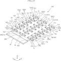
- FIG. 1 is an overall perspective view of a substrate transfer hand according to a first embodiment of the present invention. It is sectional drawing which follows the II-II line of FIG. It is sectional drawing which follows the III-III line of FIG. It is a perspective view which shows the usage example of the board
- FIG. 10 is a view taken along the line X-X in FIG. 9.
- FIG. 14 is a perspective view of a modified example of the substrate transfer hand shown in FIG. 13.
- FIG. 14 is a perspective view of another modification of the substrate transfer hand shown in FIG. 13.
- FIG. 19 is a perspective view of a modified example of the substrate transfer hand shown in FIG. 18.
- FIG. 19 is a perspective view of another modification of the substrate transfer hand shown in FIG. 18.
- FIG. 1 to 4 show a substrate transfer hand 1A according to a first embodiment of the present invention.
- This substrate transfer hand 1A is used for loading and unloading a substrate such as a large glass substrate such as 1800 mm ⁇ 1500 mm into and out of the substrate storage cassette, or into and out of the process chamber.
- the substrate transfer hand 1A is also supported by appropriate moving means and moved in a predetermined direction.
- the substrate transfer hand 1A is moved in the XYZ directions as the end effector of the articulated robot RB (FIG. 4) and is also rotated around the Z axis.
- the substrate transfer hand 1A includes a base portion 10, a vertical hand support portion 20a, and a plurality of horizontal hand support portions 31a and 32a connected to each vertical hand support portion 20a.
- the base unit 10 is a horizontal plate-like member having a certain lateral width, and is attached to a moving means such as an articulated robot RB (FIG. 4).
- the vertical hand support portion 20a extends in a horizontal straight line from the base portion 10 in the vertical direction, and in the present embodiment, the three vertical hand support portions 20a extend in parallel at regular intervals.
- the vertical hand support portion 20a is a flat bar-like member having a constant width and a constant thickness.
- a plurality of first horizontal hand support portions 31a and second horizontal hand support portions 32a that are alternately positioned in the extending direction of the vertical hand support portions 20a are connected to each vertical hand support portion 20a.
- Each of the first horizontal hand support portion 31a and the second horizontal hand support portion 32a has a certain length in the horizontal direction orthogonal to the vertical hand support portion 20a, and supports the vertical hand at the center in the length direction. It is connected to the part 20a.
- the first lateral hand support portion 31a and the second lateral hand support portion 32a are plate-like members having a constant width and a constant thickness.
- the first horizontal hand support portion 31a and the second horizontal hand support portion 32a are also provided at equal intervals in the longitudinal direction of the vertical hand support portion 20a.
- the base member 10, the vertical hand support portion 20a, the first horizontal hand support portion 31a, and the second horizontal hand support portion 32a are formed of a metal such as hard resin, ceramics, or aluminum.
- the first lateral hand support portion 31a is positioned higher than the second lateral hand support portion 32a by a predetermined height h (FIG. 2).
- the first horizontal hand support portion 31a is overlapped and connected to the vertical hand support portion 20a on the upper surface thereof, and the second horizontal hand support portion 32a is overlapped on the lower surface thereof to the vertical hand support portion 20a.
- These pins 41a, 41b, 41c, 42, and 43 can be formed of, for example, resin or rubber, but are preferably formed of a material having a certain degree of elasticity.
- Three pins 41a, 41b, and 41c are provided at three locations on the first lateral hand support portion 31a, that is, both ends in the longitudinal direction and the central portion. The position of the center pin 41b overlaps with the vertical hand member 20a.
- the three pins 41a, 41b, and 41c have the same height, and the top portion functions as the first contact 40A according to the present invention.
- Two pins 42 and 43 are provided at both ends in the longitudinal direction of the second lateral hand support portion 32a.
- the two pins 42 and 43 have the same height dimension, and are the same as the height dimensions of the pins 41a, 41b, and 41c provided on the first lateral hand support portion 31a.
- the tops of the two pins 42 and 43 function as the second contact 40B according to the present invention.
- the height position of the first contact 40A is predetermined than the height position of the second contact 40B. It is located at the top of the height h.
- pins 44 are also provided on the vertical hand support 20a.
- the top of the pin 44 functions as a third contact.
- the pin 44 protrudes at a position on the vertical hand support member 20a that equally divides the space between the pins 41b provided at the center of each first horizontal hand support portion 31a.
- the pins 44 themselves have the same height as the pins 41a, 41b, 41c provided on the first horizontal hand support portions 31a and the pins 42, 43 provided on the second horizontal hand support portions 32a.
- the position of the top of the pin 44 is lower than the top position (first contact 40A) of the pins 41a, 41b, and 41c provided on the first horizontal hand support member 31a by the thickness of the first horizontal hand support member 31a. It is higher than the top position (the second contact 40B) of the pins 42 and 43 provided on the second lateral hand support member 32a.
- FIG. 4 shows a schematic configuration when the substrate SB is transferred to the substrate receiving unit 500 of the processing apparatus CH using the substrate transfer hand 1A.
- the substrate receiving unit 500 includes left and right support members 510 and two intermediate support members 520 positioned therebetween.
- the left and right support members 510 have a comb-like shape having a vertical support portion 511 and a plurality of horizontal support portions 512 extending inward from the vertical support portion 511 at equal intervals.
- the two intermediate support members 520 include a vertical support portion 521 and a plurality of horizontal support portions 522 extending from the vertical support portion 521 to the left and right sides thereof.
- the gaps s1, s2, and s3 between the left and right support members 510 and the intermediate support member 520 and between the two intermediate support members 520 allow the substrate transfer hand 1A to pass in the vertical direction. ing.
- the substrate SB that has been placed on the substrate transfer hand 1A and advanced to the upper side of the substrate receiving unit 500 is moved from the substrate receiving unit 500 by passing the substrate transfer hand 1A through the gaps s1, s2, and s3. Also, the substrate is transferred onto the substrate receiving unit 500 while moving downward.
- the substrate SB transferred on the substrate receiving unit 500 is appropriately subjected to the next step.
- the plurality of pins 41a provided on the first horizontal hand support portion 31a, the second horizontal hand support portion 32a, and the vertical hand support portion 20a. , 41b, 41c, 42, 43, 44 are in contact with the substrate SB.
- the tip positions of the pins 41a, 41b, 41c, 42, 43, and 44, that is, the contacts with respect to the substrate SB include the first contact 40A located at the upper level and the second contact 40B lower than the first contact 40A.
- the pins 41a, 41b, 41c, 42, 43, and 44 are supported in contact with the tops of the pins 41a, 41b, 41c, 42, 43, and 44 in a state where they are intentionally bent.
- the first horizontal hand support portion 31a having the first contact 40A and the second horizontal hand support portion 32a having the lower second contact 40B at both ends are alternately provided in the extending direction of the vertical hand support portion 20a.
- the substrate SB in the supported state has a low position in the vicinity of the tip of each second horizontal hand support portion 32a in both the cross section in the side view direction and the cross section. It will be in the state which bent and changed so that it may become.
- the substrate SB is given a predetermined rigidity by such bending deformation, the mounting state on the substrate transfer hand 1A is stabilized, and the substrate SB is moved when the substrate transfer hand 1A is moved. Unnecessary vibration is reduced. Further, since the substrate SB is supported by the tips of a relatively small number of pins 41a, 41b, 41c, 42, 43, and 44, the risk of electrostatic discharge (ESD) does not increase.
- ESD electrostatic discharge
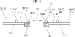
- FIGS. 5 to 8 show a substrate transfer hand 1B according to a second embodiment of the present invention.
- the same or similar members are denoted by the same or similar members as those of the substrate transfer hand 1A according to the first embodiment shown in FIGS.
- the substrate transfer hand 1B includes a base portion 10, a vertical hand support portion 20b, and a plurality of horizontal hand support portions 31b and 32b connected to each vertical hand support portion 20b.
- the base unit 10 is a horizontal plate-like member having a certain lateral width, and is attached to a moving means such as an articulated robot RB.
- the vertical hand support portion 20b extends in a horizontal straight line from the base portion 10 in the vertical direction, and in the present embodiment, the two vertical hand support portions 20b extend in parallel at regular intervals.
- the vertical hand support portion 20b is a rod-shaped member having a constant width and a constant thickness.
- a plurality of first horizontal hand support portions 31b and second horizontal hand support portions 32b that are alternately positioned in the extending direction of the vertical hand support portions 20b are connected to each vertical hand support portion 20b.
- the first horizontal hand support portions 31b and the second horizontal hand support portions 32b have a certain length in the horizontal direction perpendicular to the vertical hand support portions 20b, and are laterally outward from the vertical hand support portions 20b. It is connected so that it may extend.
- the first horizontal hand support portion 31b and the second horizontal hand support portion 32b are plate-like members having a constant width and a constant thickness.
- the first horizontal hand support portion 31b and the second horizontal hand support portion 32b are also provided at equal intervals in the longitudinal direction of the vertical hand support portion 20b.
- the base member 20, the vertical hand support portion 20b, the first horizontal hand support portion 31b, and the second horizontal hand support portion 32b are formed of a metal such as hard resin, ceramics, or aluminum.
- the first lateral hand support portion 31b is positioned higher than the second lateral hand support portion 32b by a predetermined height h (FIG. 6).
- the first horizontal hand support portion 31b is configured such that the lower surface side of the base end portion thereof is deleted in an L shape, and this deletion portion is in contact with the upper surface 201b and the side surface of the vertical hand support portion 20b. It is connected to the support portion 20b. Therefore, the upper surface 311b of the first horizontal hand support portion 31b is higher than the upper surface 201b of the vertical hand support portion 20b (FIGS. 6 and 8).
- the second horizontal hand support portion 32b is connected to the vertical hand support portion 20b so that the upper surface 321b thereof coincides with the upper surface 201b of the vertical hand support portion 20b. Accordingly, the upper surface 311b of the first horizontal hand support portion 31b is higher than the upper surface 321b of the second horizontal hand support portion 32b.
- the first lateral hand support portion 31b is provided with three pins 41a, 41b, and 41c at three locations, that is, a longitudinal base end portion, a distal end portion, and a central portion.
- the three pins 41a, 41b, and 41c have the same height, and the top portion functions as the first contact 40A according to the present invention.
- the second horizontal hand support portion 32b is provided with two pins 42 and 43 at the longitudinal end portion and the central portion.
- a pin 44 is also provided on the vertical hand support 20b adjacent to the base end of the second horizontal hand support 32b.
- the pin 44 on the vertical hand support 20b and the pin 43 at the tip of the second horizontal hand support 32b have the same height.
- These pins 43 and 44 are the same as the three pins 41a, 41b, and 41c provided on the first lateral hand support portion 31b, and the top height position is also the same.
- the height position of the tops of the pins 43 and 44 is the first lateral hand. It becomes lower than the top portions (first contact 40A) of the pins 41a, 41b, 41c provided on the support portion 31b.
- the tops of the two pins 43 and 44 function as the second contact 40B according to the present invention.
- the height of the pin 42 provided at the center portion of the second lateral hand support portion 32b is set lower than the height of the top portions of the two pins 43 and 44 constituting the second contact 40B. It is.
- the plurality of pins 41a provided on the first horizontal hand support portion 31b, the second horizontal hand support portion 32b, and the vertical hand support portion 20b. , 41b, 41c, 42, 43, 44 are in contact with the substrate SB.
- the tip positions of the pins 41a, 41b, 41c, 42, 43, and 44, that is, the contacts with respect to the substrate SB include the first contact 40A located at the upper level and the second contact 40B lower than the first contact 40A.
- the pins 41a, 41b, 41c, 42, 43, and 44 are supported in contact with the tops of the pins 41a, 41b, 41c, 42, 43, and 44 in a state where they are intentionally bent.
- the first horizontal hand support 31b having the first contact 40A and the second horizontal hand support 32b having the second contact 40B lower than the first contact 40A are alternately provided in the direction in which the vertical hand support 20b extends. Therefore, in the side view of the substrate transfer hand 1B, as shown in FIG. 6, the substrate SB in the support state is bent and deformed into a waveform.
- the vertical hand support portion 20b of the three pins 42, 43, and 44 arranged at intervals between the two vertical hand support portions 20b and arranged along the second horizontal hand support portion 32b. Since the top height of the central pin 42 is lower than the upper pin 44 and the pin 43 at the tip of the second lateral hand support portion 32b, the cross section along the second lateral hand support portion 32b is also as shown in FIG. Moreover, it will be in the state which bent and deform
- ESD electrostatic discharge
- FIGS. 9 to 12 show a substrate transfer hand 1C according to a third embodiment of the present invention.
- the same or similar members are denoted by the same or similar members as those of the substrate transfer hand 1A according to the first embodiment shown in FIGS.
- the substrate transfer hand 1C includes a base portion 10, a vertical hand support portion 20c, and a plurality of horizontal hand support portions 31c and 32c connected to each vertical hand support portion 20c.
- the base unit 10 is a horizontal plate-like member having a certain lateral width, and is attached to a moving means such as an articulated robot.
- the vertical hand support portion 20c extends in a horizontal straight line from the base portion 10 in the vertical direction.
- the two vertical hand support portions 20c extend in parallel with a predetermined interval.
- the vertical hand support portion 20c is a rod-shaped member having a constant width and a constant thickness.
- a plurality of first horizontal hand support portions 31c and second horizontal hand support portions 32c that are alternately arranged in the extending direction of the vertical hand support portions 20c are connected to each vertical hand support portion 20c.
- Each of the first horizontal hand support portions 31c and the second horizontal hand support portions 32c has a certain length in the horizontal direction orthogonal to each vertical hand support portion 20c, and inward in the left-right direction from each vertical hand support portion 20c. It is connected so that it may extend.
- the first lateral hand support portion 31c and the second lateral hand support portion 32c are plate-like members having a constant width and a constant thickness.
- the first horizontal hand support portion 31c and the second horizontal hand support portion 32c are also provided at equal intervals in the longitudinal direction of the vertical hand support portion 20c.
- the base member 10, the vertical hand support portion 20c, the first horizontal hand support portion 31c, and the second horizontal hand support portion 32c are formed of a metal such as hard resin, ceramics, or aluminum.
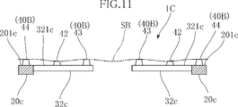
- the first lateral hand support portion 31c is positioned higher than the second lateral hand support portion 32c by a predetermined height h (FIG. 10).
- the first horizontal hand support portion 31c is configured such that the lower surface side of the base end portion is deleted in an L shape, and the deleted hand contacts the upper surface 201c and the side surface of the vertical hand support portion 20c. It is connected to the support portion 20c. Therefore, the upper surface 311c of the first horizontal hand support portion 31c is higher than the upper surface 201c of the vertical hand support portion 20c.
- the second horizontal hand support portion 32c is connected to the vertical hand support portion 20c so that the upper surface 321c thereof coincides with the upper surface 201c of the vertical hand support portion 20c. Thereby, the upper surface 311c of the first horizontal hand support portion 31c is higher than the upper surface 321c of the second horizontal hand support portion 32c.
- a plurality of pins 41a, 41b, 41c, 42, 43, 44 serving as contacts to the substrate SB to be placed on the substrate transfer hand 1C are respectively provided on the first lateral hand support portion 31c and the second lateral hand support portion 32c. Is protruding. As described above for the first and second embodiments, these pins 41a, 41b, 41c, 42, 43, and 44 can be formed of, for example, resin or rubber, but have some appropriate elasticity. It is preferable to form with a material.
- the first lateral hand support portion 31c is provided with three pins 41a, 41b, 41c at three locations, ie, a longitudinal base end portion, a distal end portion, and a central portion.
- the three pins 41a, 41b, and 41c have the same height, and the top portion functions as the first contact 40A according to the present invention.
- the second lateral hand support portion 32c is provided with two pins 42 and 43 at the longitudinal end portion and the central portion.
- a pin 44 is also provided on the vertical hand support 20c adjacent to the base end of the second horizontal hand support 32c.
- the pin 44 on the vertical hand support 20c and the pin 43 at the tip of the second horizontal hand support 32c have the same height.
- the pins 43 and 44 are the same as the three pins 41a, 41b, and 41c provided on the first lateral hand support portion 31c, and have the same height.
- the height position of the top portions of the pins 43 and 44 is the first lateral hand support. It becomes lower than the top (first contact 40A) of the pins 41a, 41b, 41c provided on the support 31c.
- the tops of the two pins 43 and 44 function as the second contact 40B according to the present invention.
- the height of the pin 42 provided in the central portion of the second lateral hand support portion 32c is made lower than the height of the top portions of the two pins 43 and 44 constituting the second contact 40B. It is.
- the tips of 42, 43, and 44 are in contact with the substrate.
- the tip positions of the pins 41a, 41b, 41c, 42, 43, and 44, that is, the contacts with respect to the substrate SB include the first contact 40A located at the upper level and the second contact 40B lower than the first contact 40A. It is supported in contact with the tops of the plurality of pins 41 a, 41 b, 41 c, 42, 43, 44 in a consciously bent state.
- first horizontal hand support portion 31c having the first contact 40A and the second horizontal hand support portion 32c having the second contact 40B lower than the first contact point 40A are alternately provided in the direction in which the vertical hand support portion 20c extends. Therefore, in the side view of the substrate transfer hand 1C, as shown in FIG. 10, the substrate SB in the support state is bent and deformed into a waveform. In addition, a space is formed between the two vertical hand support portions 20c and the distal end portions of the horizontal hand support portions 31c and 32c connected thereto, and they are arranged along the second horizontal hand support portion 32c.
- the top height of the central pin 42 is lower than the pin 44 on the vertical hand support portion 20c and the pin 43 at the tip of the second horizontal hand support portion 32c. Also in the cross section along the horizontal hand support part 32c, as shown in FIG. Accordingly, the substrate SB is given a predetermined rigidity by such bending deformation, and the mounting state on the substrate transfer hand 1C is stabilized. When the substrate transfer hand 1C is moved, Unnecessary vibration is reduced. Further, since the substrate SB is supported by the tips of a relatively small number of pins 41a, 41b, 41c, 42, 43, and 44, the risk of electrostatic discharge (ESD) does not increase.
- ESD electrostatic discharge
- FIGS. 13 to 15 show a substrate transfer hand 1D according to a fourth embodiment of the present invention.
- the same or similar members are denoted by the same or similar members as those of the substrate transfer hand 1A according to the first embodiment shown in FIGS.
- the substrate transfer hand 1D includes a base portion 10, a vertical hand support portion 20d, and a plurality of first horizontal hand support portions 31d and second horizontal hand support portions 32d connected to each vertical hand support portion 20d. .
- the base unit 10 is a horizontal plate-like member having a certain lateral width, and is attached to a moving means such as an articulated robot RB.
- the vertical hand support portion 20d extends in a horizontal straight line from the base portion 10 in the vertical direction, and in the present embodiment, the three vertical hand support portions 20d extend in parallel at regular intervals.
- the vertical hand support portion 20d is a flat bar-like member having a constant width and a constant thickness.
- a plurality of first horizontal hand support portions 31d and second horizontal hand support portions 32d that are alternately positioned in the extending direction of the vertical hand support portions 20d are connected to each vertical hand support portion 20d.
- Each of the first horizontal hand support portion 31d and the second horizontal hand support portion 32d has a certain length in the horizontal direction orthogonal to the vertical hand support portion 20d, and extends to the left and right sides of the vertical hand support portion 20d. And connected to the vertical hand support 20d.
- the first horizontal hand support portion 31d and the second horizontal hand support portion 32d are plate-like members having a constant width and a constant thickness, and their upper surfaces are the same as the upper surface of the vertical hand support portion 20d. It is in a single shape.
- the first horizontal hand support portion 31d and the second horizontal hand support portion 32d are also provided at equal intervals in the longitudinal direction of the vertical hand support portion 20d.
- the base member 10, the vertical hand support portion 20d, the first horizontal hand support portion 31d, and the second horizontal hand support portion 32d are formed of a metal such as hard resin, ceramics, or aluminum. In addition, you may shape
- a plurality of pins 41a, 41b, 42, 43 serving as contacts to the substrate SB to be placed on the substrate transfer hand 1D are respectively provided on the first horizontal hand support portion 31d and the second horizontal hand support portion 32d. ing. These pins 41a, 41b, 42, and 43 can be formed of, for example, resin or rubber, but are preferably formed of a material having a certain degree of elasticity.
- the first horizontal hand support portion 31d extending left and right from the same position in the longitudinal direction of the vertical hand support portion 20d is provided with two pins 41a and 41b, one at the distal end and a total of two pins 41a and 41b.
- the two pins 41a and 41b have the same height dimension, and the top portion functions as the first contact 40A according to the present invention.
- the second horizontal hand support portion 32d that extends alternately from the same position in the longitudinal direction of the vertical hand support portion 20d to the left and right alternately with the first horizontal hand support portion 31d has two pins in total, one at the tip portion. 42 and 43 are provided. These pins 42 and 43 have the same height dimension, but are lower than the height dimension of the pins 41a and 41b provided on the first lateral hand support portion 31d.
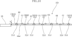
- the tops of the two pins 42 and 43 function as the second contact 40B according to the present invention. Therefore, the height position of the first contact 40A is positioned higher than the height position of the second contact 40B by a predetermined height h.
- pins 44 formed of resin, rubber, or the like project from the upper surface of the vertical hand support portion 20d in the same manner as the pins 41a, 41b, 42, 43.
- the pin 44 functions as a third contact at the top, and is provided at equal intervals in the longitudinal direction of the vertical hand support 20d.
- the pin 44 protrudes from a position corresponding to the first horizontal hand support portion 31d and a position that divides the corresponding position of each first horizontal hand support portion 31d into three equal parts.
- the height of the pin 44 is constant, but is higher than the pins 41a and 41b provided on the first horizontal hand support portion 31d and forming the first contact 40A.
- the plurality of pins 41a provided on the first horizontal hand support portion 31d, the second horizontal hand support portion 32d, and the vertical hand support portion 20d. , 41b, 42, 43, 44 are in contact with the substrate SB.
- the tip positions of the pins 41a, 41b, 42, 43, and 44, that is, the contacts with respect to the substrate SB have the first contact 40A positioned at the upper level and the second contact 40B lower than the first contact 40A.
- the pin 41a, 41b, 42, 43, 44 is supported in contact with the tops of the pins 41a, 41b, 42, 43, 44.
- first horizontal hand support portion 31d having the first contact 40A and the second horizontal hand support portion 32d having the lower second contact 40B at both ends are alternately provided in the extending direction of the vertical hand support portion 20d.
- the height of the pin 44 (third contact) provided on the vertical hand support 20d is higher than the pins 41a and 41b forming the first contact 40A and the pins 42 and 43 forming the second contact. Therefore, as shown in FIGS. 14 and 15, the substrate SB in the supported state is positioned so that the vicinity of the tip of the second lateral hand support portion 32d is low in both the cross section in the side view direction and the cross section. It will be in the state which bent and deformed.
- the substrate SB is given a predetermined rigidity by such bending deformation, the mounting state on the substrate transfer hand 1D is stabilized, and the substrate SB is moved when the substrate transfer hand 1D is moved. Unnecessary vibration is reduced. Further, since the substrate SB is supported by the tips of a relatively small number of pins 41a, 41b, 42, 43, and 44, the risk of electrostatic discharge (ESD) does not increase.
- ESD electrostatic discharge
- FIG. 16 shows a modification 1Da of the substrate transfer hand 1D according to the fourth embodiment.
- the height of the pin 44 provided in the vertical hand support portion 20d is made constant, but in the substrate transfer hand 1Da according to the modification, this pin is fixed. 44 with respect to the longitudinal direction of the vertical hand support portion 20d, for example, with respect to the height of the pin 44 at a position corresponding to each of the first horizontal hand support portion 31d and the second horizontal hand support portion 32d.
- the height of the pins 44 ′ provided between the pins 44 may be set low.
- the substrate transfer hand 1Da is also bent and deformed so that the vicinity of the front end portion of the second horizontal hand support portion 32d is low in both the cross section in the side view direction and the cross section. The same operation as that of the hand 1D can be performed.
- FIG. 17 shows another modification 1Db of the substrate transfer hand 1D according to the fourth embodiment.
- the pins 42 and 43 provided on the second horizontal hand support portion 32d all have the same height, but for the substrate transfer according to the modified example.
- the height dimension of 43a is high, for example, the same as the pins 41a and 41b provided on the first lateral hand support portion 31d.
- the substrate transfer hand 1Db is also bent and deformed so that the vicinity of the front end portion of the second horizontal hand support portion 32d provided with the pins 42 and 43 is low in both the cross section in the side view direction and the cross section. Thus, the same action as the substrate transfer hand 1D can be achieved.
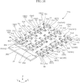
- FIGS. 18 to 20 show a substrate transfer hand 1E according to a fifth embodiment of the present invention.
- the same or similar members are denoted by the same or similar members as those of the substrate transfer hand 1A according to the first embodiment shown in FIGS.
- the substrate transfer hand 1E includes a base portion 10, a vertical hand support portion 20e, and a plurality of first horizontal hand support portions 31e and second horizontal hand support portions 32e connected to the respective vertical hand support portions 20e. .
- the substrate transfer hand 1E according to the present embodiment is similar in overall configuration to the substrate transfer hand 1D according to the fourth embodiment, but for forming the first contact 40A and the second contact 40B. Specific configuration is different.
- first horizontal hand support portion 31e and the second horizontal hand support portion 32e have a rod-like shape extending in the left-right direction from the side surface of the vertical hand support portion 20e.
- the first horizontal hand support portion 31e and the second horizontal hand support portion 32e are formed of a metal such as hard resin, ceramics, or aluminum, similarly to the vertical hand support portion 30e.
- Large-diameter portions 41a ′, 41b ′, and 42 ′ serving as contact points with respect to the substrate SB to be placed on the substrate transfer hand 1E are respectively provided at the distal ends of the first horizontal hand support portion 31e and the second horizontal hand support portion 32e. , 43 '.
- these large diameter portions 41a ′, 41b ′, 42 ′, and 43 ′ have a spherical shape.
- These large-diameter portions 41a ′, 41b ′, 42 ′, and 43 ′ can be integrally formed of a material that forms the first lateral hand support portion 31e and the second lateral hand support portion 32e. It can also be formed of an elastic material such as rubber.
- the diameters of the large diameter portions 41a ′ and 41b ′ formed on the first horizontal hand support portion 31e are larger than the diameters of the large diameter portions 42 ′ and 43 ′ formed on the second horizontal hand support portion 32e. Therefore, the top portions of the large diameter portions 41a ′ and 41b ′ function as the first contact 40A according to the present invention, and the top portions of the large diameter portions 42 and 43 function as the second contact 40B according to the present invention.
- the height position of the first contact 40A is positioned higher than the height position of the second contact 40B by a predetermined height h.
- the large diameter portions 41a ′, 41b ′, 42 ′, and 43 ′ are provided to form the first contact 40A and the second contact 40B. The specific form is not asked.
- the height of the pin 44 is constant, but the top position is higher than the first contact 40A provided on the first lateral hand support portion 31e.
- the large-diameter portions 41a ′, 41b ′, 42 provided in the first lateral hand support portion 31e and the second lateral hand support portion 32e. ', 43' and the tops of the pins 44 provided on the vertical hand support 20e are in contact with the substrate SB. Since the contact point with respect to the substrate SB includes the first contact point 40A located at the upper level and the second contact point 40B lower than the first contact point 40A, the large-diameter portions 41a ′, 41b ′, 42 are in a state where the substrate SB is intentionally bent. ', 43' and the top of the pin 44 are supported.
- first horizontal hand support portion 31e having the first contact 40A and the second horizontal hand support portion 32e having the second contact 40B lower than the first contact 40B at both ends are alternately provided in the extending direction of the vertical hand support portion 20e.
- the height dimension of the pin 44 (third contact) provided on the vertical hand support 20e is such that the large diameter portions 41a ′ and 41b ′ forming the first contact 40A and the large diameter forming the second contact 40B. Since it is higher than the tops of the portions 42 'and 43', the substrate SB in the supported state is supported by the second lateral hand both in the cross-section in the side view direction and in the cross-section as shown in FIGS.
- the substrate SB is given a predetermined rigidity by such bending deformation, the mounting state on the substrate transfer hand 1E is stabilized, and the substrate SB is moved when the substrate transfer hand 1E is moved. Unnecessary vibration is reduced. Further, since the substrate SB is supported by the relatively small number of large-diameter portions 41a ′, 41b ′, 42 ′, 43 ′ and the tops of the pins 44, the risk of electrostatic discharge (ESD) does not increase.
- ESD electrostatic discharge
- FIG. 21 shows a modification 1Ea of the substrate transfer hand 1E according to the fifth embodiment.
- the height of the pin 44 provided in the vertical hand support portion 20e is constant, but in the substrate transfer hand 1Ea according to the modification, this pin 44 with respect to the height of the pin 44 at a position corresponding to each of the first horizontal hand support portion 31e and the second horizontal hand support portion 32e.
- the height of the pins 44 ′ provided between the pins 44 may be set low.
- the substrate transfer hand 1Ea is also bent and deformed so that the vicinity of the tip end portion of the second horizontal hand support portion 32e is low in both the cross section in the side view direction and the cross section. The same action as that of the hand 1E can be achieved.
- FIG. 22 shows another modification 1Eb of the substrate transfer hand 1E according to the fifth embodiment.
- the large-diameter portions 42 ′ and 43 ′ provided in the second lateral hand support portion 32e all have the same diameter, but the substrate transfer device according to this modification example.
- the pin 42a provided on the horizontal hand support portion on the outer side in the left-right direction.
- the diameters of ', 43a' are large, for example, the same as the diameters of the large diameter portions 41a ', 41b' provided in the first lateral hand support portion 31e.
- the vicinity of the tip end portion of the second horizontal hand support portion 32e provided with the pin large-diameter portions 42 'and 43' is low in both the cross section in the side view direction and the cross section. In this way, it can be bent and deformed, and the same action as the substrate transfer hand 1E can be achieved.
- 32c, 32d, and 32e have been illustrated, other lateral hand support portions having one or more other contacts may be provided.
- the heights of the other contacts may be the same or different.
- first contact 40A, the second contact point provided on each vertical hand support 20a, 20b, 20c, 20d, 20e and each horizontal hand support 31a, 31b, 31c, 31d, 31e, 32a, 32b, 32c, 32d, 32e.
- the heights of the contacts 40B and other contacts provided as necessary are such that the substrate SB is intentionally produced in contact with these contacts and is supported on the substrate SB supported by the substrate transfer hands 1A, 1B, 1C, 1D, 1E. It can be set freely based on this.
- the second contact 40B provided on the second horizontal hand support portions 32a, 32b, 32c, 32d, and 32e is lowest, but the vertical hand support portions 20a, 20b, 20c, You may make it the 3rd contact provided in 20d and 20e become the lowest.
- the first contact 40A of each first lateral hand support portion 31a, 31b, 31c, 31d, 31e has the same height. However, even if the height of the contact is different. Good.
Landscapes
- Engineering & Computer Science (AREA)
- Mechanical Engineering (AREA)
- Robotics (AREA)
- Microelectronics & Electronic Packaging (AREA)
- Container, Conveyance, Adherence, Positioning, Of Wafer (AREA)
- Manipulator (AREA)
Abstract
Description
Claims (11)
- 基板を支持して移載するための基板移載用ハンドであって、
縦方向に延びる縦ハンド支持部と、当該縦ハンド支持部から当該縦ハンド支持部が延びる方向に対して交差する方向に延びる複数の横ハンド支持部と、を含み、
前記複数の横ハンド支持部は、複数の第1横ハンド支持部と、複数の第2横ハンド支持部とを含んでおり、
前記各第1横ハンド支持部は、それぞれ、前記基板に接することができる1または複数の第1接点を有し、当該第1接点の最高高さ位置は、第1の高さであり、
前記各第2横ハンド支持部は、それぞれ、前記基板に接することができる1または複数の第2接点を有し、当該第2接点の最高高さ位置は、前記第1の高さよりも低い第2の高さであることを特徴とする、基板移載用ハンド。 - 前記第1接点は、上方に突出するピンの頂部により構成され、前記第2接点は、上方に突出するピンの頂部により構成されている、請求項1に記載の基板移載用ハンド。
- 前記第1接点は、前記第1横ハンド支持部に形成された膨出部の頂部により構成され、前記第2接点は、前記第2横ハンド支持部に形成された膨出部の頂部により形成されている、請求項1に記載の基板移載用ハンド。
- 前記第1横ハンド支持部と、前記第2横ハンド支持部とは、前記縦方向について、交互に設けられている、請求項1ないし3のいずれかに記載の基板移載用ハンド。
- 前記各第1横ハンド支持部に複数設けられる前記第1接点の高さは一定高さであり、前記各第2横ハンド支持部に複数設けられる前記第2接点のうちの一部の高さは、前記第2の高さより低い、請求項4に記載の基板移載用ハンド。
- 前記縦ハンド支持部は、前記基板に接することができる複数の第3接点を有し、当該第3接点の最高高さ位置は、上記第2の高さと同じか、またはそれより高い、請求項1ないし5のいずれかに記載の基板移載用ハンド。
- 前記縦ハンド支持部を複数備える、請求項1ないし6いずれかに記載の基板移載用ハンド。
- 左右方向に並ぶ1対の縦ハンド支持部を備える、請求項7に記載の基板移載用ハンド。
- 前記複数の横ハンド支持部は、前記各縦ハンド支持部から左右方向外方に延びる、請求項8に記載の基板移載用ハンド。
- 前記複数の横ハンド支持部は、前記各縦ハンド支持部から左右方向内方に延びる、請求項8に記載の基板移載用ハンド。
- 前記複数の横ハンド支持部は、前記各縦ハンド支持部から左右方向両方向に延びる、請求項7に記載の基板移載用ハンド。
Priority Applications (6)
| Application Number | Priority Date | Filing Date | Title |
|---|---|---|---|
| CN202310372561.3A CN116246999B (zh) | 2016-01-29 | 2017-01-27 | 基板移载用机械手 |
| CN201780008137.3A CN108604564B (zh) | 2016-01-29 | 2017-01-27 | 基板移载用机械手 |
| US16/072,045 US10515842B2 (en) | 2016-01-29 | 2017-01-27 | Substrate transfer hand with transverse hand supports |
| CN202610009198.2A CN121888917A (zh) | 2016-01-29 | 2017-01-27 | 基板移载用机械手 |
| KR1020187024100A KR102604475B1 (ko) | 2016-01-29 | 2017-01-27 | 기판 이송용 핸드 |
| JP2017563844A JP6854245B2 (ja) | 2016-01-29 | 2017-01-27 | 基板移載用ハンド |
Applications Claiming Priority (2)
| Application Number | Priority Date | Filing Date | Title |
|---|---|---|---|
| JP2016015476 | 2016-01-29 | ||
| JP2016-015476 | 2016-01-29 |
Publications (1)
| Publication Number | Publication Date |
|---|---|
| WO2017131148A1 true WO2017131148A1 (ja) | 2017-08-03 |
Family
ID=59398491
Family Applications (1)
| Application Number | Title | Priority Date | Filing Date |
|---|---|---|---|
| PCT/JP2017/002909 Ceased WO2017131148A1 (ja) | 2016-01-29 | 2017-01-27 | 基板移載用ハンド |
Country Status (6)
| Country | Link |
|---|---|
| US (1) | US10515842B2 (ja) |
| JP (1) | JP6854245B2 (ja) |
| KR (1) | KR102604475B1 (ja) |
| CN (3) | CN108604564B (ja) |
| TW (1) | TWI725115B (ja) |
| WO (1) | WO2017131148A1 (ja) |
Families Citing this family (3)
| Publication number | Priority date | Publication date | Assignee | Title |
|---|---|---|---|---|
| JP7415782B2 (ja) * | 2020-05-11 | 2024-01-17 | 東京エレクトロン株式会社 | 基板搬送機構及び基板搬送方法 |
| KR102834790B1 (ko) * | 2023-08-30 | 2025-07-17 | 주식회사 야스 | 증착 시스템의 기판 핸들링 시스템 |
| SE2450544A1 (en) * | 2024-05-20 | 2025-11-21 | Tecnau Ab | A carrying device for carrying a stack of products |
Citations (6)
| Publication number | Priority date | Publication date | Assignee | Title |
|---|---|---|---|---|
| JP2001179672A (ja) * | 1999-12-21 | 2001-07-03 | Mitsubishi Electric Corp | ロボットハンド |
| JP2003243482A (ja) * | 2001-06-26 | 2003-08-29 | Hitachi Kiden Kogyo Ltd | 枚葉基板の移載装置並びにそれに用いる収納装置及びハンド並びにこれらの装置によって取り扱われる枚葉基板 |
| WO2004113205A1 (ja) * | 2003-06-19 | 2004-12-29 | Rorze Corporation | 薄板支持体 |
| JP2005223204A (ja) * | 2004-02-06 | 2005-08-18 | Daihen Corp | 搬送ロボット |
| JP2007008700A (ja) * | 2005-07-04 | 2007-01-18 | Toshiba Mach Co Ltd | 平板状搬送物の搬送方法及びその装置 |
| JP2009141091A (ja) * | 2007-12-06 | 2009-06-25 | Tokyo Electron Ltd | 基板保持具、基板搬送装置および基板処理システム |
Family Cites Families (15)
| Publication number | Priority date | Publication date | Assignee | Title |
|---|---|---|---|---|
| US5275521A (en) * | 1991-07-03 | 1994-01-04 | Tokyo Electron Sagami Limited | Wafer transfer device |
| JP3850951B2 (ja) * | 1997-05-15 | 2006-11-29 | 東京エレクトロン株式会社 | 基板搬送装置及び基板搬送方法 |
| US6711511B2 (en) * | 2000-07-06 | 2004-03-23 | Fujitsu Limited | Electromagnetic wave analyzing apparatus and computer readable storage medium |
| JP4681029B2 (ja) | 2001-06-26 | 2011-05-11 | 株式会社日立プラントテクノロジー | 枚葉基板の移載装置及びそれに用いるハンド |
| JP3929364B2 (ja) * | 2002-06-26 | 2007-06-13 | エスペック株式会社 | 基板支持及び出し入れ装置 |
| JP2004304055A (ja) * | 2003-03-31 | 2004-10-28 | Fujitsu Display Technologies Corp | 基板移載装置及び基板移載方法 |
| KR101023725B1 (ko) * | 2004-06-29 | 2011-03-25 | 엘지디스플레이 주식회사 | 이재 로봇 |
| KR100949502B1 (ko) * | 2005-06-20 | 2010-03-24 | 엘지디스플레이 주식회사 | 액정표시장치 제조 공정용 기판 반송장치 |
| US20070246957A1 (en) * | 2006-04-25 | 2007-10-25 | Yi-Cheng Liu | Loading device of loading a substrate capable of eliminating electrostatic charges |
| JP5107122B2 (ja) * | 2008-04-03 | 2012-12-26 | 大日本スクリーン製造株式会社 | 基板処理装置 |
| JP2012096893A (ja) * | 2010-11-02 | 2012-05-24 | Toppan Printing Co Ltd | 基板搬送台車 |
| CN202072285U (zh) * | 2011-05-24 | 2011-12-14 | 深圳市华星光电技术有限公司 | 面板传送装置及其面板支撑机构 |
| JP2013161946A (ja) * | 2012-02-06 | 2013-08-19 | Tokyo Electron Ltd | 基板処理装置及び基板処理方法 |
| US8814239B2 (en) * | 2012-02-15 | 2014-08-26 | Varian Semiconductor Equipment Associates, Inc. | Techniques for handling media arrays |
| US9061423B2 (en) * | 2013-03-13 | 2015-06-23 | Varian Semiconductor Equipment Associates, Inc. | Wafer handling apparatus |
-
2017
- 2017-01-26 TW TW106103590A patent/TWI725115B/zh active
- 2017-01-27 WO PCT/JP2017/002909 patent/WO2017131148A1/ja not_active Ceased
- 2017-01-27 CN CN201780008137.3A patent/CN108604564B/zh active Active
- 2017-01-27 CN CN202310372561.3A patent/CN116246999B/zh active Active
- 2017-01-27 KR KR1020187024100A patent/KR102604475B1/ko active Active
- 2017-01-27 JP JP2017563844A patent/JP6854245B2/ja active Active
- 2017-01-27 CN CN202610009198.2A patent/CN121888917A/zh active Pending
- 2017-01-27 US US16/072,045 patent/US10515842B2/en active Active
Patent Citations (6)
| Publication number | Priority date | Publication date | Assignee | Title |
|---|---|---|---|---|
| JP2001179672A (ja) * | 1999-12-21 | 2001-07-03 | Mitsubishi Electric Corp | ロボットハンド |
| JP2003243482A (ja) * | 2001-06-26 | 2003-08-29 | Hitachi Kiden Kogyo Ltd | 枚葉基板の移載装置並びにそれに用いる収納装置及びハンド並びにこれらの装置によって取り扱われる枚葉基板 |
| WO2004113205A1 (ja) * | 2003-06-19 | 2004-12-29 | Rorze Corporation | 薄板支持体 |
| JP2005223204A (ja) * | 2004-02-06 | 2005-08-18 | Daihen Corp | 搬送ロボット |
| JP2007008700A (ja) * | 2005-07-04 | 2007-01-18 | Toshiba Mach Co Ltd | 平板状搬送物の搬送方法及びその装置 |
| JP2009141091A (ja) * | 2007-12-06 | 2009-06-25 | Tokyo Electron Ltd | 基板保持具、基板搬送装置および基板処理システム |
Also Published As
| Publication number | Publication date |
|---|---|
| TW201738994A (zh) | 2017-11-01 |
| KR102604475B1 (ko) | 2023-11-21 |
| CN108604564A (zh) | 2018-09-28 |
| US20190035670A1 (en) | 2019-01-31 |
| CN116246999A (zh) | 2023-06-09 |
| KR20180108685A (ko) | 2018-10-04 |
| JP6854245B2 (ja) | 2021-04-07 |
| JPWO2017131148A1 (ja) | 2018-11-29 |
| CN116246999B (zh) | 2026-04-24 |
| US10515842B2 (en) | 2019-12-24 |
| TWI725115B (zh) | 2021-04-21 |
| CN108604564B (zh) | 2023-04-28 |
| CN121888917A (zh) | 2026-04-17 |
Similar Documents
| Publication | Publication Date | Title |
|---|---|---|
| US10578646B2 (en) | Testing head comprising vertical probes with internal openings | |
| US20180024166A1 (en) | Contact probe and corresponding testing head | |
| JP5845029B2 (ja) | ハウジングレスコネクタ | |
| US7835113B1 (en) | Deep dimple structure for head suspension component | |
| WO2017131148A1 (ja) | 基板移載用ハンド | |
| WO2007094237A1 (ja) | 導電性接触子および導電性接触子ユニット | |
| WO2016156002A9 (en) | Contact probe and corresponding testing head with vertical probes, particularly for high frequency applications | |
| TWI891862B (zh) | 電子裝置的探針頭的接觸探針 | |
| IT201800001170A1 (it) | Testa di misura di tipo cantilever e relativa sonda di contatto | |
| TWI837207B (zh) | 對於待測裝置具有增進的接觸性質的垂直探針頭及其探針卡 | |
| JP7285271B2 (ja) | 焼成用ラック及び焼成用治具 | |
| CN112771387A (zh) | 测量装置 | |
| JP2011106822A (ja) | 加速度センサ | |
| KR102098654B1 (ko) | 프로브 카드 | |
| CN101517832B (zh) | 电连接体 | |
| JP2006269148A (ja) | スパイラル接触子 | |
| JP6360502B2 (ja) | プローブカード | |
| CN105070563A (zh) | 键帽及应用其的按键结构 | |
| EP1321249A3 (de) | Objektgreifer für die Automatisierungstechnik | |
| JP6373011B2 (ja) | プローブカード | |
| KR20230123094A (ko) | 다층 구조를 갖는 캔틸레버 타입의 프로브 핀 및 이를 제조하는 방법 | |
| JP2012181115A (ja) | コンタクトプローブおよびプローブユニット | |
| JP2012137292A (ja) | プローブカード | |
| JP6440985B2 (ja) | シート部材、筒状部材、ワイヤハーネス、及び、凹凸形成装置 | |
| JP2009288869A (ja) | タッチパネル装置 |
Legal Events
| Date | Code | Title | Description |
|---|---|---|---|
| 121 | Ep: the epo has been informed by wipo that ep was designated in this application |
Ref document number: 17744378 Country of ref document: EP Kind code of ref document: A1 |
|
| ENP | Entry into the national phase |
Ref document number: 2017563844 Country of ref document: JP Kind code of ref document: A |
|
| NENP | Non-entry into the national phase |
Ref country code: DE |
|
| ENP | Entry into the national phase |
Ref document number: 20187024100 Country of ref document: KR Kind code of ref document: A |
|
| 122 | Ep: pct application non-entry in european phase |
Ref document number: 17744378 Country of ref document: EP Kind code of ref document: A1 |