WO2017131090A1 - タイヤ - Google Patents
タイヤ Download PDFInfo
- Publication number
- WO2017131090A1 WO2017131090A1 PCT/JP2017/002742 JP2017002742W WO2017131090A1 WO 2017131090 A1 WO2017131090 A1 WO 2017131090A1 JP 2017002742 W JP2017002742 W JP 2017002742W WO 2017131090 A1 WO2017131090 A1 WO 2017131090A1
- Authority
- WO
- WIPO (PCT)
- Prior art keywords
- tire
- pattern
- protrusions
- pattern portion
- adjacent
- Prior art date
Links
- 239000011295 pitch Substances 0.000 description 23
- 238000012360 testing method Methods 0.000 description 22
- 230000000694 effects Effects 0.000 description 13
- 230000006872 improvement Effects 0.000 description 8
- 230000002093 peripheral effect Effects 0.000 description 3
- 238000005034 decoration Methods 0.000 description 2
- 238000004519 manufacturing process Methods 0.000 description 2
- 238000000034 method Methods 0.000 description 2
- 230000004048 modification Effects 0.000 description 2
- 238000012986 modification Methods 0.000 description 2
- 238000000465 moulding Methods 0.000 description 2
- 241001672018 Cercomela melanura Species 0.000 description 1
- 230000009471 action Effects 0.000 description 1
- 230000002238 attenuated effect Effects 0.000 description 1
- 238000005452 bending Methods 0.000 description 1
- 238000011156 evaluation Methods 0.000 description 1
- 238000012545 processing Methods 0.000 description 1
- 230000009467 reduction Effects 0.000 description 1
- 238000000926 separation method Methods 0.000 description 1
- 239000007787 solid Substances 0.000 description 1
- 238000010998 test method Methods 0.000 description 1
Images


Classifications
-
- B—PERFORMING OPERATIONS; TRANSPORTING
- B60—VEHICLES IN GENERAL
- B60C—VEHICLE TYRES; TYRE INFLATION; TYRE CHANGING; CONNECTING VALVES TO INFLATABLE ELASTIC BODIES IN GENERAL; DEVICES OR ARRANGEMENTS RELATED TO TYRES
- B60C13/00—Tyre sidewalls; Protecting, decorating, marking, or the like, thereof
- B60C13/001—Decorating, marking or the like
-
- B—PERFORMING OPERATIONS; TRANSPORTING
- B60—VEHICLES IN GENERAL
- B60C—VEHICLE TYRES; TYRE INFLATION; TYRE CHANGING; CONNECTING VALVES TO INFLATABLE ELASTIC BODIES IN GENERAL; DEVICES OR ARRANGEMENTS RELATED TO TYRES
- B60C11/00—Tyre tread bands; Tread patterns; Anti-skid inserts
- B60C11/03—Tread patterns
- B60C11/13—Tread patterns characterised by the groove cross-section, e.g. for buttressing or preventing stone-trapping
-
- B—PERFORMING OPERATIONS; TRANSPORTING
- B32—LAYERED PRODUCTS
- B32B—LAYERED PRODUCTS, i.e. PRODUCTS BUILT-UP OF STRATA OF FLAT OR NON-FLAT, e.g. CELLULAR OR HONEYCOMB, FORM
- B32B3/00—Layered products comprising a layer with external or internal discontinuities or unevennesses, or a layer of non-planar shape; Layered products comprising a layer having particular features of form
- B32B3/26—Layered products comprising a layer with external or internal discontinuities or unevennesses, or a layer of non-planar shape; Layered products comprising a layer having particular features of form characterised by a particular shape of the outline of the cross-section of a continuous layer; characterised by a layer with cavities or internal voids ; characterised by an apertured layer
- B32B3/30—Layered products comprising a layer with external or internal discontinuities or unevennesses, or a layer of non-planar shape; Layered products comprising a layer having particular features of form characterised by a particular shape of the outline of the cross-section of a continuous layer; characterised by a layer with cavities or internal voids ; characterised by an apertured layer characterised by a layer formed with recesses or projections, e.g. hollows, grooves, protuberances, ribs
-
- B—PERFORMING OPERATIONS; TRANSPORTING
- B60—VEHICLES IN GENERAL
- B60C—VEHICLE TYRES; TYRE INFLATION; TYRE CHANGING; CONNECTING VALVES TO INFLATABLE ELASTIC BODIES IN GENERAL; DEVICES OR ARRANGEMENTS RELATED TO TYRES
- B60C11/00—Tyre tread bands; Tread patterns; Anti-skid inserts
- B60C11/03—Tread patterns
- B60C11/13—Tread patterns characterised by the groove cross-section, e.g. for buttressing or preventing stone-trapping
- B60C11/1353—Tread patterns characterised by the groove cross-section, e.g. for buttressing or preventing stone-trapping with special features of the groove bottom
- B60C2011/1361—Tread patterns characterised by the groove cross-section, e.g. for buttressing or preventing stone-trapping with special features of the groove bottom with protrusions extending from the groove bottom
-
- Y—GENERAL TAGGING OF NEW TECHNOLOGICAL DEVELOPMENTS; GENERAL TAGGING OF CROSS-SECTIONAL TECHNOLOGIES SPANNING OVER SEVERAL SECTIONS OF THE IPC; TECHNICAL SUBJECTS COVERED BY FORMER USPC CROSS-REFERENCE ART COLLECTIONS [XRACs] AND DIGESTS
- Y10—TECHNICAL SUBJECTS COVERED BY FORMER USPC
- Y10T—TECHNICAL SUBJECTS COVERED BY FORMER US CLASSIFICATION
- Y10T428/00—Stock material or miscellaneous articles
- Y10T428/24—Structurally defined web or sheet [e.g., overall dimension, etc.]
- Y10T428/24479—Structurally defined web or sheet [e.g., overall dimension, etc.] including variation in thickness
- Y10T428/2457—Parallel ribs and/or grooves
Definitions
- This disclosure relates to a tire on which characters and other indications are formed.
- JP-T-2009-512584 discloses a pattern portion composed of a plurality of protrusions on the surface of a tire side portion, and creates a contrast with a smooth portion adjacent to the pattern portion to visually recognize the pattern portion. A technique for improving the performance is disclosed.
- a first pattern portion in which a plurality of first protrusions are formed adjacent to each other on the tire surface, and the first pattern portion are disposed adjacent to each other.
- a second pattern part formed by adjoining a plurality of second protrusions extending in a direction different from the protrusions, and the height of the first protrusions and the second protrusions is 0.2 mm or more.
- the first protrusions adjacent to each other and the second protrusions adjacent to each other are arranged at a constant pitch of 0.15 mm or more and 0.35 mm or less.
- a first pattern portion including a plurality of first protrusions and a second pattern portion including a plurality of second protrusions are formed on the tire surface.
- the first and second ridges may be collectively referred to as “ridges”.
- the first pattern portion and the second pattern portion may be collectively referred to as “pattern portions”.
- the tire surface means a surface visible from the outside of the tire, such as a tire side portion, a tread portion, a groove bottom of the tread, and a groove wall.
- the tire includes both a pneumatic tire and a non-pneumatic (so-called solid tire) tire.
- the protrusion shows the protrusion part extended elongated along the tire surface.
- the pattern portion is constituted by a plurality of adjacent protrusions having a height dimension of 0.2 mm or more and 0.5 mm or less, and further, the adjacent protrusions have a pitch of 0.15 mm or more and 0.35 mm or less. . For this reason, when light enters between the wall surfaces of adjacent ridges, the light repeatedly reflects between the wall surfaces and gradually attenuates. Thereby, reflection of light incident on the pattern portion can be suppressed.
- the protrusions adjacent to each other are arranged at a constant pitch, the reflected light is less likely to be uneven compared to the case where the pitches are different. Further, for example, the protrusions can be arranged densely. For this reason, the reflected light is homogenized and the effect of suppressing the reflection of light is enhanced.
- the first and second ridges are extended in different directions.
- the first pattern portion and the second pattern portion can efficiently attenuate light from different directions.
- reflection of light from a plurality of directions can be suppressed.
- the protrusions whose extension direction is close to the direction perpendicular to the light direction can suppress light reflection, while the protrusions whose extension direction is close to the light direction can suppress the extension direction.
- the reflection of light is stronger than that of the protrusions close to the direction perpendicular to.
- the 1st pattern part and the 2nd pattern part reflection of light is suppressed on the one hand, and reflection of light can be strengthened on the other hand.
- a pattern is formed by the 1st pattern part and the 2nd pattern part, and visibility improves.
- the pattern part is constituted by protrusions, for example, the rubber tends to flow into the mold for molding the tire as compared with the case where the pattern part is constituted by fibrous protrusions. Therefore, the moldability of the pattern part is excellent. Further, the ridge is higher in rigidity than the fibrous protrusion and has little settling against an external force. Therefore, the durability of the pattern portion is excellent.
- an angle formed by the mutually facing wall surfaces constituting the first protrusion and the second protrusion is 15 degrees or more and 40 degrees or less.
- the ratio of the reflected light on the wall surfaces returning from between the protrusions to the outside increases, and the improvement in visibility is suppressed. Is done. That is, the light is reflected, the difference in contrast with the bright part is reduced, and the improvement in visibility is suppressed.
- the angle ⁇ is smaller than 15 °, the ridge is liable to fall down.
- the first pattern portion and the second pattern portion are alternately formed.
- the light reflection is regular as compared with the case where the first pattern portions and the second pattern portions are not alternately formed. For this reason, reflection of light can be suppressed uniformly over a wide range.
- the reflection of light incident from each direction on the pattern portion is controlled to improve the contrast while increasing the contrast between the pattern portion and the surroundings, and the pattern portion is excellent in moldability and durability.
- Tires can be provided.
- 1 is a side view of a tire according to an embodiment of the present disclosure.
- 1 is a partial perspective sectional view of a tread of a tire according to an embodiment of the present disclosure. It is a top view showing an example of the dark part of the tire concerning a 1st embodiment of this indication. It is a top view showing an example of the dark part of the tire concerning a 2nd embodiment of this indication. It is a top view showing a modification of a dark part of a tire concerning an embodiment of this indication.
- It is sectional drawing which expanded and showed the 1st protrusion which comprises the dark part of embodiment of this indication.
- It is sectional drawing which expanded and showed the 2nd protrusion which comprises the dark part of embodiment of this indication.
- FIG. 1 shows a side view of a tire 10 according to this embodiment.
- the tire circumferential direction is indicated by C
- the tire radial direction is indicated by R.
- the tire 10 may be a pneumatic tire or a non-pneumatic tire.
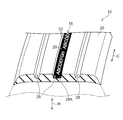
- the tire side part 12 (decoration part) which comprises a tire surface is formed with a first mark part 14 and a second mark part 16 that form a display.
- the 1st mark part 14 and the 2nd mark part 16 are made into strip
- the first mark part 14 and the second mark part 16 have a dark part 20 that appears black in appearance and a bright part 22 that appears brighter than the dark part 20.
- the 1st mark part 14 and the 2nd mark part 16 may be arrange
- the bright portion 22 is composed of, for example, characters “ABCDEFGH” formed with a smooth surface, and the dark portion 20 is formed on the outer peripheral portion of the bright portion 22. Is formed.
- the dark portion 20 is a kind of decorative band, and is formed so as to surround the character formed by the bright portion 22.
- the letters “ABCDEFGH” are formed by the dark portion 20, and the outer peripheral portion of the dark portion 20 is composed of the bright portion 22.
- the light part 22 constitutes a kind of decorative band and is provided so as to surround the character formed by the dark part 20.
- the bright portion 22 is formed of a smooth surface in the same manner as the general surface 12A constituting the surface other than the mark portion of the tire side portion 12, and the bright portion 22 is a stepped surface that is recessed inward from the general surface 12A. 12B.
- the tire 10 includes a tread 26 on the outer side in the tire radial direction R.
- a plurality of circumferential grooves 28 are formed in the tread 26.
- a third mark portion 18 that forms a display is formed on the groove bottom 28A (decoration portion) of the circumferential groove 28 that constitutes the tire surface.
- the third mark portion 18 has a belt shape and is formed in a part of the circumferential groove 28.
- the third mark portion 18 also has a dark portion 20 that appears black in appearance and a bright portion 22 that appears brighter than the dark portion 20.
- the bright portion 22 is composed of, for example, characters “ABCDEFGH” formed with a smooth surface, and the dark portion 20 is formed on the outer peripheral portion of the bright portion 22.
- the dark portion 20 is a kind of decorative band, and is formed so as to surround the character formed by the bright portion 22.
- the 1st mark part 14, the 2nd mark part 16, and the 3rd mark part 18 including the dark part 20 can be formed by providing the unevenness
- the dark portion 20 of the first mark portion 14 includes a first pattern portion 30 formed on a step surface 12 ⁇ / b> B that recedes inward from the general surface 12 ⁇ / b> A (see FIG. 1) of the tire side portion 12,
- the second pattern unit 40 is configured.
- the first pattern portion 30 has a ridge 32 which is an example of the first ridge of the present disclosure in which the ridge line CL is linear in a plan view, along the tire surface and in a direction orthogonal to the extending direction of the ridge 32. Are arranged adjacent to each other in parallel.
- the 2nd pattern part 40 is orthogonal to the extension direction of the protrusion 42 along the tire surface, and the protrusion 42 which is an example of the 2nd protrusion of this indication extended in the direction orthogonal to the protrusion 32 is provided.
- a plurality are arranged in parallel along the direction.
- the first pattern portion 30 and the second pattern portion 40 are alternately arranged adjacent to each other, forming a checkered pattern (in other words, a lattice pattern).
- the dark part 20 of the other 2nd mark part 16 and the 3rd mark part 18 is also made into the same structure. The same applies to the following description.
- the protrusion 32 has a wall surface 32A protruding in the protruding direction (see FIG. 6) so that the interval between the wall surfaces 32A on both sides gradually increases from the top portion 32B to the base portion 32C. 6A is inclined with respect to the direction indicated by the arrow Y.
- the wall surface 32A of the ridge 32 continuously extends linearly from the top portion 32B to the base portion 32C.
- the “base portion 32C” refers to a boundary portion between the protrusion 32 and the step surface 12B.
- the top 32B is a flat surface when the ridge 32 is viewed in a cross section in a direction orthogonal to the extending direction, and the height H of the ridge 32, that is, along the tire radial direction from the top 32B to the step surface 12B.
- the dimension is 0.3 mm or more and 0.4 mm or less.
- this embodiment demonstrates the case where the height H of the protrusion 32 is set to 0.3 mm or more and 0.4 mm or less, embodiment of this indication is not limited to this.
- the height H can be in a range of 0.2 mm or more and 0.5 mm or less, and a predetermined effect can be obtained within this range.
- the dark portion 20 is configured so that light is repeatedly reflected and attenuated between the wall surface 32A of one protrusion 32 and the wall surface 32A of the other protrusion 32 in the space between adjacent protrusions 32 to appear dark.
- the height H of the ridge 32 is less than 0.3 mm, the effect of making it appear black starts to be reduced, and when the height H is less than 0.2 mm, the effect is significantly reduced.
- the height dimension H of the protrusion 32 exceeds 0.4 mm, the protrusion 32 is likely to be deformed by an external force, and when the height H exceeds 0.5 mm, it is difficult to ensure the formability during manufacturing.
- the height H of the protrusion 32 is suitably 0.2 mm or more and 0.5 mm or less, and more preferably 0.3 mm or more and 0.4 mm or less.
- the pitch P of the adjacent ridges 32 is an equal pitch of 0.2 mm or more and 0.3 mm or less. This pitch P is represented by the separation distance of the ridgeline CL of the ridge 32.
- the ridge line CL is a center line of the top portion 32B (in other words, a line along the extending direction of the protrusion 32), and is indicated by a one-dot chain line in FIG.
- the pitch P of the adjacent protrusion 32 is set to 0.2 mm or more and 0.3 mm or less
- embodiment of this indication is not limited to this.
- the pitch P can be in the range of 0.15 mm or more and 0.35 mm or less, and within this range, a predetermined effect can be obtained.
- the space between adjacent protrusions 32 is darkened so that it looks black.
- the pitch P of the adjacent ridges 32 exceeds 0.3 mm, the effect of making it appear black due to the space between the ridges 32 starts, and when the pitch P exceeds 0.35 mm, the reduction in the effect is significant. Become. On the other hand, if the pitch P is less than 0.15 mm, the moldability is deteriorated.
- the pitch P of the adjacent protrusions 32 is suitably 0.15 mm or more and 0.35 mm or less, and the pitch P is more preferably 0.2 mm or more and 0.3 mm or less.
- the wall surfaces 32A on both sides are inclined, and the angle ⁇ formed by the opposing wall surfaces 32A in the adjacent ridges 32 is set to 15 degrees or more and 40 degrees or less. For this reason, it becomes easy to die-cut at the time of manufacture of a tire, and a moldability improves. As a result, the falling is reduced and the durability is improved.
- the angle ⁇ formed by the wall surface 32A of the protrusion 32 is less than 15 degrees, the protrusion 32 is easily deformed and falls easily.
- the angle ⁇ formed by the wall surface 32A of the protrusion 32 exceeds 40 degrees, the rate at which the reflected light on the wall surface 32A is emitted from the dark portion 20 increases.
- the angle ⁇ formed by the wall surface 32A of the adjacent protrusion 32 is 15 degrees or more and 40 degrees or less.
- the configuration of the ridge 32 forming the first pattern portion 30 has been described above, but the ridge 42 forming the second pattern portion 40 has the same configuration as shown in FIG. 6B.
- a first mark portion 14, a second mark portion 16, and a third mark portion 18 that form a display are provided on the groove bottom 28 ⁇ / b> A of the tire side portion 12 and the circumferential groove 28 of the tread 26.
- the dark part 20 constituting the first mark part 14, the second mark part 16 and the third mark part 18 is adjacent to a protrusion 32 having a height H of 0.3 mm or more and 0.4 mm or less.
- the first pattern portion 30 and the protrusion 42 extending in the direction orthogonal to the protrusion 32 are constituted by the second pattern portion 40 adjacently disposed.
- the extending directions of the protrusions 32 and 42 arranged in the first pattern portion 30 and the second pattern portion 40 are different from each other, in the dark portion 20 including the first pattern portion 30 and the second pattern portion 40.
- the reflection of light incident on the tire 10 from each direction can be suppressed.
- it looks black even if it sees from various angles visibility improves.
- the pitch P of the adjacent ridges 32 and 42 is configured to be equidistant from 0.2 mm to 0.3 mm. For this reason, the protrusions 32 and 42 can be densely arranged compared with the case where the protrusions 32 and 42 are arranged apart from each other. Thereby, the dark part 20 can be made to appear blacker.
- the wall surfaces 32A and 42A of the protrusions 32 and 42 are inclined, and the angle ⁇ formed by the wall surfaces 32A and 42A facing each other in the adjacent protrusions 32 and 42 is set to 15 degrees or more and 40 degrees or less. .
- the angle formed between the wall surfaces is greater than 15 degrees, the ratio of the reflected light on the wall surfaces returning from between the ridges to the outside increases, and the improvement in visibility is suppressed. That is, the light is reflected, the difference in contrast with the bright part is reduced, and the improvement in visibility is suppressed.
- the angle ⁇ is smaller than 15 °, the ridge is liable to fall down.
- the angle ⁇ exceeds 40 degrees, the rate at which the reflected light on the wall surface 32A is emitted from the dark part 20 becomes significant. For this reason, visibility can be negotiated while maintaining the shape of the ridge.
- the top portions 32B and 42B of the protrusions 32 and 42 are flat surfaces. For this reason, compared with the case where a flat surface is not formed, the top parts 32B and 42B have high rigidity, and the durability of the protrusions 32 and 42 is improved.
- the top portions 32B and 42B of the ridges 32 and 42 are flat surfaces.
- the embodiment of the present disclosure is not limited to this, and for example, the top portions 32B of the ridges 32 and 42 are provided. , 42B may be pointed vertices.
- the top portions 32B and 42B may have a curved shape such as an arc. Even if the top portions 32B and 42B are curved, it is possible to prevent the reflected light from being directly recognized.
- the wall surface 32A and 42A of the protrusions 32 and 42 extend linearly as illustrated in FIGS. 6A and 6B has been described, but the embodiment of the present disclosure is not limited thereto. It is not limited, The wall surface may extend in the shape of a curve, and may be bent in a polygonal line shape, a zigzag shape, or the like. In this way, the light is irregularly reflected between the wall surfaces 32A and 42A as compared with the case of extending linearly. Therefore, it is possible to bring the reflected light in the first pattern portion and the second pattern portion closer to each other.
- FIG. 7 shows a part of the first mark portion 14.
- the characters that make up the bright portion 22 are formed of a smooth surface and have gloss, and reflect light.
- the surroundings of the bright part 22 are composed of a dark part 20, and the dark part 20 absorbs light and suppresses reflection of light. For this reason, in the bright part 22 which reflects light, and the dark part 20 which absorbs light, contrast is raised and the visibility of the character displayed on the 1st mark part 14 can be improved.
- the first pattern portion 30 and the second pattern portion 40 are adjacent to each other in the direction along the direction in which the first protrusion 32 extends and the direction perpendicular thereto.
- the second pattern portion 40 forms a checkered pattern (in other words, a lattice pattern)
- the embodiment of the present disclosure is not limited to this.
- the adjacent direction of the first pattern portion 30 and the second pattern portion 40 is inclined by 45 ° with respect to the extending direction of the first protrusion 32, and the first pattern portion 30 and the second pattern portion 40 are staggered. You may arrange in a shape.
- the inclination angle is not limited to 45 °, and can be appropriately selected.
- the state in which the first pattern portions 30 and the second pattern portions 40 are alternately formed in the present disclosure is that the adjacent directions of the first pattern portions 30 and the second pattern portions 40 are limited. Instead, the general state in which the fixed region of the tire side portion 12 is covered by the regular arrangement of the first pattern portion 30 and the second pattern portion 40 is shown.
- the base portion 32C is a portion where the flat wall surface 32A and the flat step surface 12B intersect, and is viewed in a cross section in a direction perpendicular to the extending direction of the protrusion 32 in a polygonal line shape.
- the embodiment of the present disclosure is not limited to this.
- the base portion 32 ⁇ / b> C may be formed so as to draw a curve when viewed in a cross section in a direction orthogonal to the extending direction of the protrusion 32. That is, the wall surface 32A and the step surface 12B may be connected by the curved base portion 32C.
- the step surface 12B may be formed in a curved surface shape.
- FIG. 4 shows the dark portion 20 in the second embodiment.
- the ridges 52 and 62 of the second embodiment are configured such that the ridge line CL is formed in an arc shape in plan view, and the first pattern portion 50 and the second pattern portion 60 are configured by arranging a plurality of ridges 52 and 62 adjacent to each other. Has been.
- interval are adjusted so that the virtual line L which tied the edge part of the protrusions 52 adjacent to each other and the protrusions 62 may also become circular arc shape.
- the ridgelines CL of the ridges 52 and 62 are formed in an arc shape as indicated by arrows M and N in FIG. Therefore, the incident light hardly passes linearly between the wall surfaces 52A and 62A of the protrusions 52 and 62. For this reason, reflection is repeated between the wall surfaces 52A and 62A. Therefore, the light attenuation effect can be enhanced as compared with the case where the ridge line CL of the ridge is formed in a straight line.
- FIG. 5 shows a modification of the embodiment of the present disclosure.
- the ridge line CL of the ridge can be formed in a zigzag shape in a plan view, for example. Even if the ridge line CL is formed in a zigzag shape, as indicated by arrows M and N in FIG. 5, the incident light can be repeatedly reflected between the wall surfaces of the ridges to enhance the light attenuation effect.
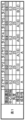
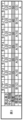
- Test conditions As the test tires, tires having a size of 205 / 55R16 and a tire cross-section height SH of 114 mm were used.
- the dark portion 20 constituting the first mark portion 14 has a height dimension H of the protrusion 32 of 0.35 mm, a pitch P of 0.2 mm, and an angle ⁇ formed by the wall surface 32A of the adjacent protrusion 32 being 25 degrees as a reference. Value.
- an evaluation test was performed using test tires having the height dimension H, the pitch P, or the angle ⁇ as shown in Tables 1 to 3.
- Test method In the test, the visibility when the dark part 20 of the first mark part 14 was viewed from each direction was evaluated. First, each test tire was assembled on an applied rim, and then 20 observers observed to conduct a questionnaire survey on whether the dark part 20 appeared blacker than a normal tire. The results are shown in Tables 1 to 3 as “visibility” (see FIGS. 8 to 10).
- the occurrence of bears on the protrusions constituting the pattern part of each test tire was visually evaluated, and the formability of the pattern part was evaluated using the bear occurrence rate in the pattern part as an index.
- the results are shown in Table 1 as “formability”.
- the formability of the pattern portion is represented by A when the bear occurrence rate is less than 0.1%, and the pattern is produced when the bear occurrence rate is less than 0.1 to 0.3%.
- the moldability of the pattern part was represented by B, and the moldability of the pattern part was represented by C when the bear generation rate was 0.3% or more.
- Test 1 In Test 1, as shown in Table 1 of FIG. 8, tires 1 to 6 in which the height H of the protrusion 32 was changed were prepared and tested. In addition, except the height H, it is set as the above-mentioned reference value.
- the pitch P is set to 0.3 mm so that the angle ⁇ formed by the wall surface 32 ⁇ / b> A of the ridge 32 is 25 degrees and the heights H are 0.5 mm and 0.6 mm, respectively.
- Test 2 In Test 2, as shown in Table 2 of FIG. 9, tires 1 to 7 in which the pitch P of the protrusions 32 was changed were prepared and tested. Except for the pitch P, the above-mentioned reference values are used.
- the visibility is improved in the range where the pitch P is 0.15 mm or more and 0.35 mm or less, and the visibility is further improved in the range where the pitch P is 0.2 mm or more and 0.3 mm or less. An improvement was observed.
- Test 3 In Test 3, as shown in Table 3 of FIG. 10, tires 1 to 7 in which the angle ⁇ formed by the wall surface 32A of the adjacent protrusion 32 was changed were prepared and tested. Except for the angle ⁇ , the above-mentioned reference value is used.
Landscapes
- Engineering & Computer Science (AREA)
- Mechanical Engineering (AREA)
- Tires In General (AREA)
Abstract
タイヤは、タイヤ表面に、第1突条が複数隣接して形成される第1パターン部と、平面視で第1突条と異なる方向に延設された第2突条が複数隣接して形成される第2パターン部と、を備え、第1突条及び第2突条の高さが0.2mm以上0.5mm以下とされ、互いに隣接する第1突条同士及び互いに隣接する第2突条同士が0.15mm以上0.35mm以下の一定ピッチで配置されている。
Description
本開示は、文字などの表示が形成されたタイヤに関する。
特表2009-512584号公報には、タイヤサイド部の表面に複数の突起で構成されたパターン部を形成し、該パターン部に隣接する平滑部との間でコントラストを生じさせてパターン部の視認性を向上させる技術について開示されている。
ところで、特表2009-512584号公報に開示された技術のように、突起を点在させてパターン部を構成する場合、成形時においてモールドに設けられた突起成形用の孔にゴムが流れ込み難く、突起の成形性を確保するのが難しい傾向がある。また、成形される突起は繊維状であり摩耗に対する耐性を確保することが難しい。
本開示は、上記事実を考慮して、パターン部に対して各方向から入射される光の反射を制御してパターン部と周囲とのコントラストを高めつつ視認性を向上させ、複数の突起で構成されるパターン部の成形性及び耐久性に優れたタイヤを提供することを課題とする。
本開示の第1態様のタイヤは、タイヤ表面に、第1突条が複数隣接して形成される第1パターン部と、前記第1パターン部に隣接して配置され、平面視で前記第1突条と異なる方向に延設された第2突条が複数隣接して形成される第2パターン部と、を備え、前記第1突条及び前記第2突条の高さが0.2mm以上0.5mm以下とされ、互いに隣接する前記第1突条同士及び互いに隣接する前記第2突条同士が0.15mm以上0.35mm以下の一定ピッチで配置されている。
本開示の第1態様のタイヤは、タイヤ表面に複数の第1突条で構成された第1パターン部及び複数の第2突条で構成された第2パターン部が形成されている。(以下、第1突条及び第2突条を総称して「突条」と称することがある。また、第1パターン部及び第2パターン部を総称して「パターン部」と称することがある。)ここで、タイヤ表面とは、タイヤサイド部、トレッド部、トレッドの溝底、溝壁など、タイヤの外側から視認可能な表面をいう。また、タイヤとしては、空気入りタイヤ、非空気入り(所謂ソリッドタイヤ)タイヤの両方を含む。なお、突条とはタイヤ表面に沿って細長く延設された突出部を示している。
パターン部は、高さ寸法が0.2mm以上0.5mm以下の突条が複数隣接して構成され、さらに、互いに隣接する突条同士が0.15mm以上0.35mm以下のピッチとされている。このため、隣接した突条の壁面間に光が入射すると、光は壁面間で反射を繰り返し、次第に減衰する。これによりパターン部に対して入射される光の反射を抑制することができる。
互いに隣接する突条同士は一定ピッチで配置されているため、ピッチがバラバラな場合と比較して、反射光にムラが生じにくい。さらに、例えば突条を密に配置することができる。このため、反射光が均質化され、また光の反射を抑制する効果が高められている。
また、第1突条と第2突条とは異なる方向に延設されている。このため、第1パターン部と第2パターン部は、互いに異なる方向からの光を効率的に減衰させることができる。これにより複数方向からの光の反射を抑制することができる。また、延設方向が光の方向に直交する方向に近い突条では、光の反射を抑制することができる一方、延設方向が光の方向に近い突条では、延設方向が光の方向に直交する方向に近い突条と比較して、光の反射が強くなる。このため、第1パターン部と第2パターン部では、一方で光の反射が抑制され、他方で光の反射を強めることができる。このため、第1パターン部と第2パターン部によって模様が形成され、視認性が向上する。
さらに、パターン部は突条により構成されているため、例えばパターン部が繊維状の突起により構成されている場合と比較して、タイヤを成形するモールドにゴムが流れ易い。したがって、パターン部の成形性に優れる。また、突条は繊維状の突起と比較して剛性が高く、外力に対するへたりが少ない。したがって、パターン部の耐久性に優れる。
本開示の第2態様のタイヤは、第1態様のタイヤにおいて、前記第1突条及び前記第2突条を構成する互いに対向した壁面同士の成す角度が15度以上40度以下とされている。
本開示の第2態様のタイヤによると、壁面同士の成す角度が15度よりも大きいと、壁面での反射光が、突条の間から外側へ戻る割合が多くなり、視認性の向上が抑制される。すなわち、光が反射して、明部とのコントラストの差異が小さくなり、視認性の向上が抑制される。一方、角度θが15°よりも小さいと、突条が倒れやすくなる。
本開示の第3態様のタイヤは、第1及び第2態様のタイヤにおいて、前記第1パターン部と前記第2パターン部とが交互に形成されている。
本開示の第3態様のタイヤによると、第1パターン部と前記第2パターン部が交互に形成されていない場合と比較して、光の反射が規則的になる。このため広い範囲に亘って光の反射を均質に抑制することができる。
本開示によれば、パターン部に対して各方向から入射される光の反射を制御してパターン部と周囲とのコントラストを高めつつ視認性を向上させ、パターン部の成形性及び耐久性に優れたタイヤを提供することができる。
[第1実施形態]
以下、図面を参照して、本開示の第1実施形態について説明する。図1には、本実施形態に係るタイヤ10の側面図が示されている。本実施形態では、タイヤ周方向をC、タイヤ径方向をRで示す。なお、このタイヤ10は、空気入りタイヤであってもよいし、非空気入りタイヤであってもよい。
以下、図面を参照して、本開示の第1実施形態について説明する。図1には、本実施形態に係るタイヤ10の側面図が示されている。本実施形態では、タイヤ周方向をC、タイヤ径方向をRで示す。なお、このタイヤ10は、空気入りタイヤであってもよいし、非空気入りタイヤであってもよい。
(標章部)
タイヤ表面を構成するタイヤサイド部12(装飾部)には、表示を形成する第1標章部14及び第2標章部16が形成されている。第1標章部14及び第2標章部16は、帯状の円弧状とされ、タイヤ中心軸CEを挟んで対称位置に形成されている。また、第1標章部14及び第2標章部16は、外観上黒く見える暗部20と、暗部20より明るく見える明部22とを有している。なお、第1標章部14及び第2標章部16は、タイヤ最大幅部(すなわち、タイヤサイド部間の直線距離が最大となる部分)よりもタイヤ径方向の外側に配置されることが好ましい。
タイヤ表面を構成するタイヤサイド部12(装飾部)には、表示を形成する第1標章部14及び第2標章部16が形成されている。第1標章部14及び第2標章部16は、帯状の円弧状とされ、タイヤ中心軸CEを挟んで対称位置に形成されている。また、第1標章部14及び第2標章部16は、外観上黒く見える暗部20と、暗部20より明るく見える明部22とを有している。なお、第1標章部14及び第2標章部16は、タイヤ最大幅部(すなわち、タイヤサイド部間の直線距離が最大となる部分)よりもタイヤ径方向の外側に配置されることが好ましい。
図1の紙面上側に設けられた第1標章部14では、明部22が平滑面で形成された例えば「ABCDEFGH」の文字で構成されており、この明部22の外周部に暗部20が形成されている。この暗部20は、一種の装飾帯であり、明部22で形成された文字を囲むように形成されている。
一方、図1の紙面下側に設けられた第2標章部16では、暗部20によって例えば「ABCDEFGH」の文字が形成されており、この暗部20の外周部は、明部22で構成されている。この第2標章部16では、明部22が一種の装飾帯を構成し、暗部20で形成された文字を囲むように設けられている。この明部22は、タイヤサイド部12の標章部以外の表面を構成する一般面12Aと同様に平滑面で構成されており、当該明部22は、一般面12Aより内側に後退した段差面12Bで構成されている。
また、タイヤ10は、図2に示すように、タイヤ径方向Rの外側にトレッド26を備えている。トレッド26には、複数の周方向溝28が形成されている。タイヤ表面を構成する周方向溝28の溝底28A(装飾部)には、表示を形成する第3標章部18が形成されている。第3標章部18は、帯状とされ、周方向溝28の一部に形成されている。この第3標章部18も、外観上黒く見える暗部20と、暗部20より明るく見える明部22とを有している。
この第3標章部18では、明部22が平滑面で形成された例えば「ABCDEFGH」の文字で構成されており、この明部22の外周部に暗部20が形成されている。この暗部20は、一種の装飾帯であり、明部22で形成された文字を囲むように形成されている。
なお、暗部20を含む第1標章部14、第2標章部16及び第3標章部18は、レーザー加工によってタイヤ10のモールド内に対応する凹凸を設けることによって、形成することができる。
(パターン部)
第1標章部14の暗部20は、図3に示すように、タイヤサイド部12の一般面12A(図1参照)より内側に後退した段差面12Bに形成された第1パターン部30と、第2パターン部40とで構成されている。第1パターン部30は、稜線CLが平面視で直線状とされた本開示の第1突条の一例である突条32をタイヤ表面に沿ってかつ突条32の延設方向と直交する方向に沿って複数平行に隣接配置して構成されている。第2パターン部40は、突条32と直交する方向に延設された本開示の第2突条の一例である突条42をタイヤ表面に沿ってかつ突条42の延設方向と直交する方向に沿って複数平行に配置して構成されている。第1パターン部30と第2パターン部40は互いに隣接して交互に配置され、市松模様(換言すると、格子状模様)を形成している。なお、他の第2標章部16及び第3標章部18の暗部20も同様の構造とされている。以下の説明についても同様である。
第1標章部14の暗部20は、図3に示すように、タイヤサイド部12の一般面12A(図1参照)より内側に後退した段差面12Bに形成された第1パターン部30と、第2パターン部40とで構成されている。第1パターン部30は、稜線CLが平面視で直線状とされた本開示の第1突条の一例である突条32をタイヤ表面に沿ってかつ突条32の延設方向と直交する方向に沿って複数平行に隣接配置して構成されている。第2パターン部40は、突条32と直交する方向に延設された本開示の第2突条の一例である突条42をタイヤ表面に沿ってかつ突条42の延設方向と直交する方向に沿って複数平行に配置して構成されている。第1パターン部30と第2パターン部40は互いに隣接して交互に配置され、市松模様(換言すると、格子状模様)を形成している。なお、他の第2標章部16及び第3標章部18の暗部20も同様の構造とされている。以下の説明についても同様である。
(突条)
突条32は、図6Aに示すように、延在方向と直交する方向の断面で見て、両側の壁面32A間の間隔が頂部32Bから基部32Cにかけて漸増するように壁面32Aが突出方向(図6Aでは、矢印Yで示す方向)に対して傾斜している。また、本実施形態では、突条32の壁面32Aが頂部32Bから基部32Cに亘って連続して直線状に延びている。なお、ここでいう「基部32C」とは、突条32と段差面12Bとの境界部分を指している。
突条32は、図6Aに示すように、延在方向と直交する方向の断面で見て、両側の壁面32A間の間隔が頂部32Bから基部32Cにかけて漸増するように壁面32Aが突出方向(図6Aでは、矢印Yで示す方向)に対して傾斜している。また、本実施形態では、突条32の壁面32Aが頂部32Bから基部32Cに亘って連続して直線状に延びている。なお、ここでいう「基部32C」とは、突条32と段差面12Bとの境界部分を指している。
頂部32Bは、突条32を延在方向と直交する方向の断面で見て平坦面とされており、突条32の高さH、すなわち頂部32Bから段差面12Bまでのタイヤ径方向に沿った寸法は0.3mm以上0.4mm以下とされている。
なお、本実施形態では、突条32の高さHを、0.3mm以上0.4mm以下に設定した場合について説明するが、本開示の実施形態はこれに限定されるものではない。例えば、この高さHは、0.2mm以上0.5mm以下の範囲とすることができ、この範囲内であれば、所定の効果を得ることができる。
なお、本実施形態では、突条32の高さHを、0.3mm以上0.4mm以下に設定した場合について説明するが、本開示の実施形態はこれに限定されるものではない。例えば、この高さHは、0.2mm以上0.5mm以下の範囲とすることができ、この範囲内であれば、所定の効果を得ることができる。
暗部20では、隣接する突条32間の空間で、一方の突条32の壁面32Aと他方の突条32の壁面32A間で光を繰り返し反射し減衰させて暗く見せるように構成されている。
このとき、突条32の高さHが0.3mm未満だと黒く見せる効果の減少が始まり、高さHが0.2mm未満だと、その効果の減少が顕著となる。一方、突条32の高さ寸法Hが0.4mmを超えると、外力による突条32の変形が生じやすく、高さHが0.5mmを超えると、製造時における成形性の確保が難しい。
このため、突条32の高さHは0.2mm以上0.5mm以下とすることが適当であり、高さHを0.3mm以上0.4mm以下とすることがさらに好ましい。
隣接する突条32のピッチPは、0.2mm以上0.3mm以下の等間隔ピッチとされている。このピッチPは、突条32の稜線CLの離間距離で表される。稜線CLは頂部32Bの中心線(換言すると、突条32の延設方向に沿った線)であり、図3に一点鎖線で示されている。
なお、本実施形態では、隣接する突条32のピッチPを、0.2mm以上0.3mm以下に設定した場合について説明するが、本開示の実施形態はこれに限定されるものではない。例えば、このピッチPは、0.15mm以上0.35mm以下の範囲とすることができ、この範囲内であれば、所定の効果を得ることができる。
暗部20では、隣接する突条32間の空間を暗くして黒く見えるようにしている。しかし、隣接する突条32のピッチPが0.3mmを超えると、突条32間の空間によって黒く見せる効果の減少が始まり、ピッチPが0.35mmを超えると、その効果の減少が顕著となる。また、ピッチPが0.15mm未満となると成形性が悪くなる。
このため、隣接する突条32のピッチPは、0.15mm以上0.35mm以下とすることが適当であり、ピッチPは、0.2mm以上0.3mm以下とすることがさらに好ましい。
突条32は、両側の壁面32Aが傾斜しており、隣接する突条32において対向した壁面32Aが成す角度θは、15度以上40度以下に設定されている。このため、タイヤの製造時に型抜きしやすくなり、成形性が向上する。その結果、倒れ込みが少なくなり、耐久性が向上する。
ここで、突条32の壁面32Aが成す角度θを15度未満にすると、突条32が変形し倒れ易くなる。一方、突条32の壁面32Aが成す角度θが40度を超えると、壁面32Aでの反射光が暗部20から放出される率が増加する。
このため、隣接した突条32の壁面32Aが成す角度θは、15度以上40度以下となるように設定することが適当である。
以上、第1パターン部30を形成する突条32の構成について説明したが、図6Bに示すように第2パターン部40を構成する突条42も同様の構成とされている。
(作用・効果)
次に、本実施形態に係るタイヤの作用及び効果について説明する。タイヤサイド部12やトレッド26の周方向溝28の溝底28Aには、表示を形成する第1標章部14、第2標章部16及び第3標章部18が設けられている。これらの第1標章部14、第2標章部16及び第3標章部18を構成する暗部20は、高さHが、0.3mm以上0.4mm以下の突条32が隣接して配置された第1パターン部30及び突条32と直交する方向に延設された突条42が隣接して配置された第2パターン部40で構成されている。
次に、本実施形態に係るタイヤの作用及び効果について説明する。タイヤサイド部12やトレッド26の周方向溝28の溝底28Aには、表示を形成する第1標章部14、第2標章部16及び第3標章部18が設けられている。これらの第1標章部14、第2標章部16及び第3標章部18を構成する暗部20は、高さHが、0.3mm以上0.4mm以下の突条32が隣接して配置された第1パターン部30及び突条32と直交する方向に延設された突条42が隣接して配置された第2パターン部40で構成されている。
このため、例えば突条32の壁面32Aと直交する方向に近い方向から光が入射した際には、図3に矢印Mで示すように、突条32の壁面32A間で光の反射回数が多くなり光が減衰され、第1パターン部30は黒く見える。一方、図3に矢印Nで示すように、突条42の壁面42A間では光の反射回数が少なくなり、第2パターン部40の光の減衰効果は第1パターン部30と比較して低減され、黒さは抑えられる。
逆に、例えば突条42の壁面42Aと直交する方向に近い方向から光が入射した際には、第2パターン部40のほうが第1パターン部30と比較して黒く見える。このように、第1パターン部30と第2パターン部40にそれぞれ配置された突条32、42の延設方向が異なるため、第1パターン部30及び第2パターン部40を備えた暗部20では、タイヤ10に各方向から入射される光の反射を抑制することができる。また、様々な角度から見ても黒く見えるので、視認性が向上する。
逆に、例えば突条42の壁面42Aと直交する方向に近い方向から光が入射した際には、第2パターン部40のほうが第1パターン部30と比較して黒く見える。このように、第1パターン部30と第2パターン部40にそれぞれ配置された突条32、42の延設方向が異なるため、第1パターン部30及び第2パターン部40を備えた暗部20では、タイヤ10に各方向から入射される光の反射を抑制することができる。また、様々な角度から見ても黒く見えるので、視認性が向上する。
また、隣接する突条32、42のピッチPが0.2mm以上0.3mm以下の等間隔となるように構成されている。このため、突条32、42を、隣接間隔をバラバラにして配置した場合と比較して、突条32、42を密に配置することができる。これにより、暗部20をより黒く見せることができる。
そして、突条32、42の壁面32A、42Aはそれぞれ傾斜しており、隣接する突条32、42において対向した壁面32A、42Aの成す角度θが、15度以上40度以下に設定されている。
壁面同士の成す角度が15度よりも大きいと、壁面での反射光が、突条の間から外側へ戻る割合が多くなり、視認性の向上が抑制される。すなわち、光が反射して、明部とのコントラストの差異が小さくなり、視認性の向上が抑制される。一方、角度θが15°よりも小さいと、突条が倒れやすくなる。また、角度θが40度を超えると、壁面32Aでの反射光が暗部20から放出される率が顕著となる。このため、突条の形状を保持しつつ視認性を交渉させることができる。
また、突条32、42の頂部32B、42Bは平坦面とされている。このため、平坦面が形成されない場合と比較して頂部32B、42Bの剛性が高く、突条32、42の耐久性が向上している。
なお、本実施形態においては突条32、42の頂部32B、42Bは平坦面とされているが、本開示の実施形態はこれに限定されるものではなく、例えば突条32、42の頂部32B、42Bは尖った形状の頂点としてもよい。この場合、頂部32Bが平坦面とされている場合と比較して、反射光が直接視認されることを抑制できる。このためパターン部30、40のコントラストを高くして視認性を高めることができる。あるいは、頂部32B、42Bは円弧などの曲面状とされていてもよい。頂部32B、42Bが曲面状とされていても、反射光が直接視認されることを抑制できる。
なお、上述の実施形態では、突条32、42の壁面32A、42Aが図6A、図6Bに示されるように直線状に延びている場合についてのみ説明したが、本開示の実施形態はこれに限定されるものではなく、壁面は曲線状に延びていてもよいし、折れ線状、ジグザグ状等に屈曲していてもよい。このようにすれば、直線状に延びている場合と比較して壁面32A、42A間で光が乱反射する。したがって第1パターン部と第2パターン部における反射光の見え方を近づけることができる。
図7には、第1標章部14の一部が示されている。明部22を構成する文字は、平滑面で構成され光沢を有しており、光が反射する。この明部22の周りは、暗部20で構成されており、この暗部20では、光が吸収され、光の反射が抑制される。このため、光が反射する明部22と光を吸収する暗部20とにおいて、コントラストが高められ、第1標章部14に表示された文字の視認性を向上することができる。
なお、本実施形態においては、第1パターン部30と第2パターン部40との隣接方向を、第1突条32の延設方向に沿った方向及び垂直な方向として、第1パターン部30と第2パターン部40とは市松模様(換言すると、格子状模様)を形成しているものとしたが、本開示の実施形態はこれに限定されるものではない。例えば第1パターン部30と第2パターン部40との隣接方向を、第1突条32の延設方向に対して45°傾斜させて、第1パターン部30と第2パターン部40とを千鳥状に配置してもよい。また、傾斜角度も45°に限定されるものではなく、適宜選択することができる。このように、本開示における第1パターン部30と第2パターン部40とが交互に形成されている状態とは、第1パターン部30と第2パターン部40との隣接方向が限定されるものではなく、タイヤサイド部12の一定領域が第1パターン部30及び第2パターン部40の規則的な配置によって被覆されている状態全般を示す。
また、本実施形態において基部32Cは、平面である壁面32Aと平面である段差面12Bとが交差する部分であり、突条32の延在方向と直交する方向の断面で見て、折れ線状に屈曲して形成されているが、本開示の実施形態はこれに限定されるものではない。例えば基部32Cは突条32の延在方向と直交する方向の断面で見て、曲線を描くように形成されていてもよい。すなわち、壁面32Aと段差面12Bとが、曲面状の基部32Cによって連結されていてもよい。あるいは、段差面12Bが曲面状に形成されていてもよい。このように形成することで、光の反射を抑制し、パターン部30のコントラストを高くして視認性を高めることができる。
[第2実施形態]
次に、本開示の第2実施形態について説明する。なお、第1実施形態と同様の構成については同一の符号を付して、説明は適宜省略する。図4には第2実施形態における暗部20が示されている。
次に、本開示の第2実施形態について説明する。なお、第1実施形態と同様の構成については同一の符号を付して、説明は適宜省略する。図4には第2実施形態における暗部20が示されている。
第2実施形態の突条52、62は、稜線CLが平面視で円弧状に形成され、第1パターン部50、第2パターン部60はそれぞれ、突条52、62を複数隣接配置して構成されている。なお、互いに隣接する突条52同士、突条62同士の端部を結んだ仮想線Lも円弧状となるように隣接方向及び隣接間隔が調整されている。
第2実施形態の第1パターン部50、第2パターン部60に光が入射すると、図4に矢印M、Nで示したように、突条52、62の稜線CLが円弧状に形成されているため、入射光は突条52、62の壁面52A、62A間を直線的に通過しにくい。このため壁面52A、62A間で反射を繰り返す。したがって、突条の稜線CLが直線状に形成されている場合と比較して、光の減衰効果を高めることができる。
また、図5には、本開示の実施形態の変形例が示されている。図5に示すように、突条の稜線CLは例えば平面視でジグザグ状とすることもできる。稜線CLをジグザグ状としても、図5に矢印M、Nで示したように、入射光は突条の壁面間で反射を繰り返し、光の減衰効果を高めることができる。
<試験例>
本開示の効果を立証するために、以下の試験1~試験3を実施した。
本開示の効果を立証するために、以下の試験1~試験3を実施した。
(試験条件)
供試タイヤとしては、いずれもサイズが205/55R16でタイヤ断面高さSHが114mmのタイヤを用いた。
供試タイヤとしては、いずれもサイズが205/55R16でタイヤ断面高さSHが114mmのタイヤを用いた。
供試タイヤには、第1標章部14を設けた。第1標章部14を構成する暗部20は、突条32の高さ寸法Hが0.35mm、ピッチPが0.2mm、隣接する突条32の壁面32Aが成す角度θが25度を基準値とした。各試験において、高さ寸法H、ピッチP、又は角度θを、表1~表3に示す値とする供試タイヤを用いて評価試験を行った。
(試験方法)
試験では、第1標章部14の暗部20を各方向から見たときの視認性について評価した。まず、それぞれの供試タイヤを適用リムに組み付け、その後、20人の看者が観察して、通常のタイヤよりも暗部20が黒く見えるかのアンケート調査を行った。その結果を「視認性」として表1~表3に示す(図8~図10参照)。
試験では、第1標章部14の暗部20を各方向から見たときの視認性について評価した。まず、それぞれの供試タイヤを適用リムに組み付け、その後、20人の看者が観察して、通常のタイヤよりも暗部20が黒く見えるかのアンケート調査を行った。その結果を「視認性」として表1~表3に示す(図8~図10参照)。
また試験では、各供試タイヤのパターン部を構成する突起に対するベアの発生を目視で評価し、パターン部におけるベアの発生率を指標にパターン部の成形性を評価した。その結果を「成形性」として表1に示す。なお、表1~表3では、ベアの発生率が0.1%未満の場合にパターン部の成形性をAで表し、ベアの発生率が0.1~0.3%未満の場合にパターン部の成形性をBで表し、ベアの発生率が0.3%以上の場合にパターン部の成形性をCで表した。
なお、各表では、暗部20が黒く明確に見えたと回答した看者の数が18人以上の場合をA、10~17人の場合をB、9人以下の場合をCとして評価した。なお各表には、暗部20が黒く明確に見えたと回答した看者の人数も併記した。また、各表における「突出高さ」、「中心間隔」、「角度」は、それぞれ以下の記載の「高さH」、「ピッチP」、「角度θ」に相当する。
(試験1)
試験1では、図8の表1に示したように、突条32の高さHを変化させたタイヤ1~タイヤ6を用意して試験を行った。なお、高さH以外は、前述の基準値とする。
試験1では、図8の表1に示したように、突条32の高さHを変化させたタイヤ1~タイヤ6を用意して試験を行った。なお、高さH以外は、前述の基準値とする。
表1に示されるように、高さHが、0.2mm以上0.5mm以下の範囲では、視認性が向上しており、高さHが、0.3mm以上0.4mm以下の範囲では、さらなる視認性の向上が認められた。また、高さHが、0.5mm以下の範囲では成形性が向上しており、0.4mm以下の範囲では、さらなる成形性の向上が認められた。なお、タイヤ5、6においては、突条32の壁面32Aが成す角度θを25度とし、高さHをそれぞれ0.5mm、0.6mmとするために、ピッチPは0.3mmとしている。
(試験2)
試験2では、図9の表2に示したように、突条32のピッチPを変化させたタイヤ1~タイヤ7を用意して試験を行った。なお、ピッチP以外は、前述の基準値とする。
試験2では、図9の表2に示したように、突条32のピッチPを変化させたタイヤ1~タイヤ7を用意して試験を行った。なお、ピッチP以外は、前述の基準値とする。
表2に示されるように、ピッチPが0.15mm以上0.35mm以下の範囲では、視認性が向上しており、ピッチPが0.2mm以上0.3mm以下の範囲では、さらなる視認性の向上が認められた。
(試験3)
試験3では、図10の表3に示したように、隣接する突条32の壁面32Aが成す角度θを変化させたタイヤ1~タイヤ7を用意して試験を行った。なお、角度θ以外は、前述の基準値とする。
試験3では、図10の表3に示したように、隣接する突条32の壁面32Aが成す角度θを変化させたタイヤ1~タイヤ7を用意して試験を行った。なお、角度θ以外は、前述の基準値とする。
表3に示されるように、角度θが15度以上40度以下の範囲で視認性の向上が確認できた。
2016年1月27日に出願された日本国特許出願2016-013633号の開示は、その全体が参照により本明細書に取り込まれる。本明細書に記載されたすべての文献、特許出願、および技術規格は、個々の文献、特許出願、および技術規格が参照により取り込まれることが具体的かつ個々に記された場合と同程度に、本明細書中に参照により取り込まれる。
Claims (3)
- タイヤ表面に、第1突条が複数隣接して形成される第1パターン部と、
前記第1パターン部に隣接して配置され、平面視で前記第1突条と異なる方向に延設された第2突条が複数隣接して形成される第2パターン部と、
を備え、前記第1突条及び前記第2突条の高さが0.2mm以上0.5mm以下とされ、互いに隣接する前記第1突条同士及び互いに隣接する前記第2突条同士が0.15mm以上0.35mm以下の一定ピッチで配置されたタイヤ。 - 前記第1突条及び前記第2突条を構成する互いに対向した壁面同士の成す角度が15度以上40度以下とされた、請求項1に記載のタイヤ。
- 前記第1パターン部と前記第2パターン部とが交互に形成されている、請求項1又は請求項2に記載のタイヤ。
Priority Applications (3)
| Application Number | Priority Date | Filing Date | Title |
|---|---|---|---|
| EP17744320.7A EP3409510B1 (en) | 2016-01-27 | 2017-01-26 | Tire |
| US16/073,025 US10730353B2 (en) | 2016-01-27 | 2017-01-26 | Tire |
| CN201780008287.4A CN108602398A (zh) | 2016-01-27 | 2017-01-26 | 轮胎 |
Applications Claiming Priority (2)
| Application Number | Priority Date | Filing Date | Title |
|---|---|---|---|
| JP2016-013633 | 2016-01-27 | ||
| JP2016013633A JP6694282B2 (ja) | 2016-01-27 | 2016-01-27 | タイヤ |
Publications (1)
| Publication Number | Publication Date |
|---|---|
| WO2017131090A1 true WO2017131090A1 (ja) | 2017-08-03 |
Family
ID=59398499
Family Applications (1)
| Application Number | Title | Priority Date | Filing Date |
|---|---|---|---|
| PCT/JP2017/002742 WO2017131090A1 (ja) | 2016-01-27 | 2017-01-26 | タイヤ |
Country Status (5)
| Country | Link |
|---|---|
| US (1) | US10730353B2 (ja) |
| EP (1) | EP3409510B1 (ja) |
| JP (1) | JP6694282B2 (ja) |
| CN (1) | CN108602398A (ja) |
| WO (1) | WO2017131090A1 (ja) |
Families Citing this family (1)
| Publication number | Priority date | Publication date | Assignee | Title |
|---|---|---|---|---|
| JP7151226B2 (ja) * | 2018-07-10 | 2022-10-12 | 住友ゴム工業株式会社 | タイヤ |
Citations (5)
| Publication number | Priority date | Publication date | Assignee | Title |
|---|---|---|---|---|
| JPH11291722A (ja) * | 1998-04-03 | 1999-10-26 | Bridgestone Corp | 多数のリッジよりなる環状装飾体を備えた空気入りタイヤ |
| JP2014121978A (ja) * | 2012-12-21 | 2014-07-03 | Yokohama Rubber Co Ltd:The | 空気入りタイヤ |
| JP2014136487A (ja) * | 2013-01-16 | 2014-07-28 | Sumitomo Rubber Ind Ltd | 空気入りタイヤ |
| JP2014162447A (ja) * | 2013-02-27 | 2014-09-08 | Yokohama Rubber Co Ltd:The | 空気入りタイヤ |
| JP2015529170A (ja) * | 2012-09-12 | 2015-10-05 | コンパニー ゼネラール デ エタブリッスマン ミシュラン | 複数個の空所を含むハイコントラストパターンを有するタイヤ |
Family Cites Families (11)
| Publication number | Priority date | Publication date | Assignee | Title |
|---|---|---|---|---|
| US4823856A (en) * | 1984-12-19 | 1989-04-25 | The Goodyear Tire & Rubber Company | Serrated outline marking for a tire side wall |
| US6253815B1 (en) * | 1998-08-14 | 2001-07-03 | Michelin Recherche Et Techniques S.A. | Design pattern for a tire |
| FR2892336B1 (fr) | 2005-10-21 | 2009-10-09 | Michelin Soc Tech | Marquage offrant une meilleure visibilite et procede de marquage. |
| JP5160345B2 (ja) | 2008-08-26 | 2013-03-13 | 東洋ゴム工業株式会社 | 空気入りタイヤ |
| JP4687811B2 (ja) * | 2009-04-10 | 2011-05-25 | 横浜ゴム株式会社 | 空気入りタイヤ |
| ITMI20120012U1 (it) | 2012-01-17 | 2013-07-18 | T A Pneumatici S N C Di Totino Fr Anco & C | Pneumatico migliorato per veicoli in genere |
| DE102012104890A1 (de) * | 2012-06-05 | 2013-12-05 | Continental Reifen Deutschland Gmbh | Polymerprodukt, vorzugsweise Fahrzeugreifen |
| FR3007324B1 (fr) | 2013-06-20 | 2015-07-17 | Michelin & Cie | Pneumatique comportant un marquage a fort contraste |
| FR3020594B1 (fr) | 2014-04-30 | 2018-01-05 | Compagnie Generale Des Etablissements Michelin | Pneumatique comportant un symbole matriciel a fort contraste sur le flanc |
| JP6617040B2 (ja) | 2016-01-25 | 2019-12-04 | 株式会社ブリヂストン | タイヤ |
| JP6768300B2 (ja) * | 2016-01-25 | 2020-10-14 | 株式会社ブリヂストン | タイヤ |
-
2016
- 2016-01-27 JP JP2016013633A patent/JP6694282B2/ja active Active
-
2017
- 2017-01-26 WO PCT/JP2017/002742 patent/WO2017131090A1/ja active Application Filing
- 2017-01-26 US US16/073,025 patent/US10730353B2/en active Active
- 2017-01-26 CN CN201780008287.4A patent/CN108602398A/zh active Pending
- 2017-01-26 EP EP17744320.7A patent/EP3409510B1/en active Active
Patent Citations (5)
| Publication number | Priority date | Publication date | Assignee | Title |
|---|---|---|---|---|
| JPH11291722A (ja) * | 1998-04-03 | 1999-10-26 | Bridgestone Corp | 多数のリッジよりなる環状装飾体を備えた空気入りタイヤ |
| JP2015529170A (ja) * | 2012-09-12 | 2015-10-05 | コンパニー ゼネラール デ エタブリッスマン ミシュラン | 複数個の空所を含むハイコントラストパターンを有するタイヤ |
| JP2014121978A (ja) * | 2012-12-21 | 2014-07-03 | Yokohama Rubber Co Ltd:The | 空気入りタイヤ |
| JP2014136487A (ja) * | 2013-01-16 | 2014-07-28 | Sumitomo Rubber Ind Ltd | 空気入りタイヤ |
| JP2014162447A (ja) * | 2013-02-27 | 2014-09-08 | Yokohama Rubber Co Ltd:The | 空気入りタイヤ |
Also Published As
| Publication number | Publication date |
|---|---|
| US10730353B2 (en) | 2020-08-04 |
| EP3409510B1 (en) | 2020-07-29 |
| EP3409510A4 (en) | 2018-12-19 |
| JP6694282B2 (ja) | 2020-05-13 |
| EP3409510A1 (en) | 2018-12-05 |
| CN108602398A (zh) | 2018-09-28 |
| JP2017132351A (ja) | 2017-08-03 |
| US20190030960A1 (en) | 2019-01-31 |
Similar Documents
| Publication | Publication Date | Title |
|---|---|---|
| WO2017130986A1 (ja) | タイヤ | |
| WO2017135149A1 (ja) | タイヤ | |
| WO2017131091A1 (ja) | タイヤ | |
| WO2017131019A1 (ja) | タイヤ | |
| JP6411949B2 (ja) | タイヤ | |
| JP6549412B2 (ja) | タイヤ | |
| WO2017131090A1 (ja) | タイヤ | |
| JP6441170B2 (ja) | タイヤ | |
| JP6436861B2 (ja) | タイヤ | |
| JP6495736B2 (ja) | タイヤ | |
| JP2016215703A (ja) | タイヤ | |
| JP6436860B2 (ja) | タイヤ | |
| JP2017136959A (ja) | タイヤ | |
| JP2016215700A (ja) | タイヤ | |
| JP6549413B2 (ja) | タイヤ | |
| US20200307323A1 (en) | Tire |
Legal Events
| Date | Code | Title | Description |
|---|---|---|---|
| 121 | Ep: the epo has been informed by wipo that ep was designated in this application |
Ref document number: 17744320 Country of ref document: EP Kind code of ref document: A1 |
|
| NENP | Non-entry into the national phase |
Ref country code: DE |
|
| WWE | Wipo information: entry into national phase |
Ref document number: 2017744320 Country of ref document: EP |
|
| ENP | Entry into the national phase |
Ref document number: 2017744320 Country of ref document: EP Effective date: 20180827 |