WO2017126680A1 - 弾性クローラ - Google Patents
弾性クローラ Download PDFInfo
- Publication number
- WO2017126680A1 WO2017126680A1 PCT/JP2017/001989 JP2017001989W WO2017126680A1 WO 2017126680 A1 WO2017126680 A1 WO 2017126680A1 JP 2017001989 W JP2017001989 W JP 2017001989W WO 2017126680 A1 WO2017126680 A1 WO 2017126680A1
- Authority
- WO
- WIPO (PCT)
- Prior art keywords
- lug
- crawler
- elastic
- circumferential direction
- lugs
- Prior art date
- Legal status (The legal status is an assumption and is not a legal conclusion. Google has not performed a legal analysis and makes no representation as to the accuracy of the status listed.)
- Ceased
Links
Images






Classifications
-
- B—PERFORMING OPERATIONS; TRANSPORTING
- B62—LAND VEHICLES FOR TRAVELLING OTHERWISE THAN ON RAILS
- B62D—MOTOR VEHICLES; TRAILERS
- B62D55/00—Endless track vehicles
- B62D55/08—Endless track units; Parts thereof
- B62D55/18—Tracks
- B62D55/24—Tracks of continuously flexible type, e.g. rubber belts
- B62D55/253—Tracks of continuously flexible type, e.g. rubber belts having elements interconnected by one or more cables or like elements
Definitions
- the present invention relates to an elastic crawler.
- the conventional elastic crawler has a lug formed on the outer peripheral surface of the crawler main body (base) for the purpose of uniformizing the spring characteristics of the entire elastic crawler (rubber crawler) and suppressing vibration and improving the service life.
- An object of the present invention is to provide an elastic crawler with improved soil removal properties.
- An elastic crawler according to the present invention is formed of an endless belt-shaped crawler body formed of an elastic body, and is formed to protrude from the outer peripheral surface of the crawler main body, provided at intervals in the crawler circumferential direction, and in the crawler width direction.
- the first lug that extends and the first lugs that are adjacent to each other in the crawler circumferential direction protrude from the outer circumferential surface of the crawler body, and extend while being inclined with respect to the crawler circumferential direction and the crawler width direction. And at least one second lug.
- the elastic crawler according to the present invention it is preferable that at least one end of the second lug in the extending direction of the second lug is connected to the first lug. In this case, excellent soil removal properties can be obtained.
- both ends of the second lug are connected to the first lug in the extending direction.
- the effect of improving the soil removal property can be obtained over a long period of time while enhancing the soil removal property.
- the second lug includes an inflection portion that changes an extending direction of the second lug.
- the soil removal property can be further improved.
- the protruding height of the second lug from the outer peripheral surface of the crawler main body is lower than the protruding height of the first lug from the outer peripheral surface of the crawler main body. In this case, the soil removal property can be further improved.
- the width of the second lug in the direction orthogonal to the extending direction of the second lug is larger than the width of the first lug in the direction orthogonal to the extending direction of the first lug.
- Narrow is preferred. In this case, the soil removal property can be further improved.
- the angle formed by the extending direction of the second lug and the crawler circumferential direction is at least a part of the extending direction of the second lug and is adjacent to the first lug adjacent to the crawler circumferential direction. It is preferable to become smaller as it gets closer. In this case, the soil removal property can be further improved.
- the angle formed by the extending direction of the second lug and the crawler circumferential direction is at least a part of the extending direction of the second lug and is adjacent to the first lug adjacent to the crawler circumferential direction. It is preferable to increase as it approaches. In this case, the soil removal property can be further improved.
- the top portion of the second lug is linearly deformed when wound on a rotating wheel provided in a machine body that drives the elastic crawler.
- the soil removal property can be further improved.
- the first lug extends incline toward one side of the crawler in the crawler width direction from the outer side in the crawler width direction
- the second lug extends from the outer side in the crawler width direction to the inner side. It is preferable to extend incline toward one side of the crawler circumferential direction as it goes. In this case, the soil removal property can be further improved.
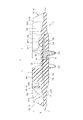
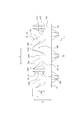
- FIG. 2 is a cross-sectional view taken along the line AA in FIG. It is a side view of FIG. It is a perspective view which shows a part of elastic crawler of FIG. 1 from the crawler outer peripheral surface side.
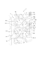
- FIG. 2 is an enlarged plan view of FIG. 1. It is a perspective view which shows a part of elastic crawler concerning the 2nd Embodiment of this invention from the crawler outer peripheral surface side.
- FIG. 7 is a side view of FIG. 6. It is a perspective view which shows a part of elastic crawler concerning the 3rd Embodiment of this invention from the crawler outer peripheral surface side.
- FIG. 11B is three-dimensional data showing the analysis result using the model of FIG.
- (A) is the three-dimensional data which shows the model used in order to carry out FEM analysis of the strain distribution which arises when it winds around the rotation wheel with which an airframe is equipped about the elastic crawler concerning a 3rd embodiment of the present invention.
- (b) is three-dimensional data showing the analysis result using the model of FIG. It is a top view which shows a part of elastic crawler concerning the 4th Embodiment of this invention from the crawler outer peripheral surface side.
- the symbol L indicates the crawler circumferential direction
- the symbol W indicates the crawler width direction
- symbol D shows the crawler thickness direction.
- FIG. 1 to 5 show an elastic crawler 1 according to a first embodiment of the present invention.
- the elastic crawler 1 according to the present embodiment is assumed to rotate from the lower side toward the upper side in FIG.
- Reference numeral 11 denotes a crawler main body formed in an endless belt shape by an elastic body.
- the crawler body 11 is made of an elastic body of vulcanized rubber.
- reference numeral 12 denotes a cored bar embedded in the crawler main body 11.
- a plurality of core bars 12 are embedded at intervals in the crawler circumferential direction.
- Each of the core bars 12 has a center portion 12a and a pair of wing portions 12b extending outward in the crawler width direction with the center portion 12a interposed therebetween.
- a pair of protrusions 12 c that protrude toward the inner peripheral surface of the crawler are provided at the center 12 a of the cored bar 12.
- the two protrusions 12c are arranged at an interval in the crawler width direction.
- the protrusion 12 c is covered with an elastic body together with the crawler main body 11.
- reference numeral 13 denotes a tensile body embedded in the crawler main body 11.
- the tensile body 13 is formed of, for example, a steel cord.
- the tensile body 13 is continuously arranged in the crawler width direction by, for example, being wound in a spiral shape in the crawler circumferential direction or by joining both end portions of the tensile body 13 after being formed in a banded end shape.
- a reinforcing layer or the like can be embedded in the crawler main body 11 at least one of the crawler inner peripheral surface side and the crawler outer peripheral surface side of the tensile body 13.
- the elastic crawler 1 is provided with a pair of roller rolling surfaces 11a on the inner peripheral surface side of the crawler.
- the two roller rolling surfaces 11 a are formed on the inner peripheral surface of the crawler body 11.
- the two rolling wheel rolling surfaces 11a are arranged at intervals in the crawler width direction with the two protrusions 12c interposed therebetween. As shown in FIG. 3, the rolling wheel rolling surface 11 a extends in the crawler circumferential direction.
- the outer peripheral surface of the crawler body 11 is arranged at the center of the crawler width and is formed as a flat surface along the crawler width direction.
- the outer peripheral surface 11f2 is formed as a flat surface inclined toward the peripheral surface side.
- the elastic crawler 1 is provided with a plurality of first lugs R1 and a plurality of second lugs R2 on the outer peripheral surface side of the crawler.
- the first lugs R1 are formed so as to protrude from the outer peripheral surface (11f1, 11f2) of the crawler body 11, and are provided at intervals in the crawler circumferential direction and extend in the crawler width direction.
- the first lug R1 is disposed between the core bars 12 adjacent in the crawler circumferential direction.
- 1st lug R1 is provided in 2 rows at intervals in the crawler width direction.
- a plurality of first lugs R1 are provided at intervals in the crawler circumferential direction on the outer side in the crawler width direction (left and right sides in the drawing) across the crawler width center line O, respectively.
- the first lugs R1 arranged in two rows at intervals in the crawler width direction are respectively spaced from the crawler width center line O by the same interval in the crawler width direction, and in the same crawler width direction. It is arranged on the line. That is, in the elastic crawler 1 according to the present embodiment, the first lugs R1 are arranged symmetrically with respect to the crawler width center line O, respectively.
- the first lug R1 is configured by the long lug 14 or the short lug 15.
- the long lugs 14 and the short lugs 15 are alternately arranged in the crawler circumferential direction.
- the long lug 14 has the main tread part 14a, as shown in FIG.1 and FIG.4.
- the main tread surface portion 14a projects from the outer peripheral surface 11f1 of the crawler main body portion 11 in a tapered manner, and the top portion forms the tread surface 14f1.
- the main tread surface portion 14 a is inclined between the core bars 12 adjacent in the crawler circumferential direction from the crawler width direction center side toward the crawler width direction outer side in plan view of the crawler outer circumference.
- the main tread surface portion 14a is disposed at a position where the end portion 14e1 in one extending direction is adjacent to one cored bar 12 adjacent in the crawler circumferential direction on the crawler width center side, and in the other extending direction.
- the end portion 14e2 is disposed at a position adjacent to the other cored bar 12 adjacent in the crawler circumferential direction on the outer side in the crawler width direction.
- the long lug 14 has a sub tread surface portion 14b connected to the main tread surface portion 14a.
- the auxiliary tread surface portion 14b projects from the outer peripheral surface 11f2 of the crawler main body portion 11 in a tapered manner, and the top surface forms the tread surface 14f2.
- the sub tread surface portion 14 b extends from the main tread surface portion 14 a toward the outside along the crawler width direction in a plan view of the crawler outer peripheral side.
- the sub tread surface portion 14b has one end in the extending direction continuous to the end portion 14e2 in the extending direction of the main tread surface portion 14a, and the other extending direction end 14e3 in the crawler of the crawler body 11.
- the tread surface 14f1 of the main tread surface portion 14a is a horizontal surface having a uniform height in the crawler thickness direction
- the tread surface 14f2 of the sub tread surface portion 14b is In the crawler thickness direction, it is inclined toward the inner peripheral surface of the crawler main body 11 as it goes to the outside of the crawler width.
- the short lug 15 also has a main tread surface portion 15a as shown in FIG.
- the main tread surface portion 15a is a main tread surface portion having the same shape as the long lug 14. That is, the main tread surface portion 15a of the short lug 15 has a tread surface 15f1 similar to the tread surface 14f1 of the long lug 14, and the crawler circumferential direction one side (in FIG. ) And extend in parallel and are arranged in parallel to each other.
- the main tread surface portion 14a of the long lug 14 and the main tread surface portion 15a of the short lug 15 extend incline toward one side of the crawler circumferential direction from the outer side to the inner side in the crawler width direction, and are parallel to each other. Is arranged.
- the short lug 15 has a sub tread surface portion 15b connected to the main tread surface portion 15a.
- the sub tread surface portion 15b of the short lug 15 projects from the outer peripheral surface 11f2 of the crawler main body portion 11 in a tapered manner, and the top portion forms a top surface 15f2.
- the sub-tread surface portion 15 b of the short lug 15 extends from the main tread surface portion 15 a toward the outside along the crawler width direction in a plan view of the crawler outer peripheral side.
- the sub tread 15b of the short lug 15 has one end in the extending direction continuous to the end 15e2 in the extending direction of the main tread 15a, and the other end 15e3 in the extending direction is the crawler body.
- the portion 11 is disposed at a position on the inner side in the crawler width direction than the outer edge 11e in the crawler width direction. That is, the sub tread surface portion 15 b of the short lug 15 is shorter in the crawler width direction than the sub tread surface portion 14 b of the long lug 14. More specifically, as shown in FIGS. 2 to 4, the sub tread surface portion 15b of the short lug 15 is closer to the outer side of the crawler width in the crawler thickness direction than the sub tread surface portion 14b of the long lug 14 is.
- the portion 11 is inclined more greatly on the inner peripheral surface side and is connected to the outer peripheral surface 11 f 2 of the crawler main body portion 11.
- the second lug R2 is formed to protrude from the outer peripheral surface 11f1 of the crawler main body 11 between the first lugs R1 adjacent to each other in the crawler circumferential direction, and in the crawler outer peripheral side plan view, the crawler circumferential direction and the crawler width direction And at least one end in the extending direction is connected to the first lug R1.
- the second lug R2 is formed to protrude from the outer peripheral surface 11f1 of the crawler body 11 between the long lug 14 and the short lug 15, Between the long lugs 14 and the short lugs 15 that are adjacent to each other in the crawler circumferential direction, it is inclined from the center side in the crawler width direction toward the outside in the crawler width direction.
- the second lug R ⁇ b> 2 has one end in the extending direction connected to the long lug 14 and the other end connected to the short lug 15.
- the second lug R2 is configured as the second lug 16 (hereinafter, the second lug R2 is also referred to as “second lug 16”). As shown in FIG.
- the second lug 16 has one end 16e1 in the extending direction connected to one long lug 14 adjacent to the crawler in the circumferential direction on the center side in the crawler width direction, and the other extending in the other direction.
- the end 16e2 in the existing direction is connected to the other short lug 15 adjacent in the crawler circumferential direction on the outer side in the crawler width direction.
- the second lug 16 protrudes from the outer peripheral surface 11f1 of the crawler main body 11, and its top forms a top surface 16f1.
- one end portion of the top surface 16f1 is connected to the tread surface 14f1 of the long lug 14, and the other end portion of the top surface 16f1 is connected to the main tread surface top surface 15f1 of the short lug 15.
- the top surface 16 f 1 of the second lug 16 is more peripheral than the top surface 14 f 1 of the long lug 14 and the top surface 15 f 1 of the short lug 15.
- the height protruding from the surface 11f1 is configured to be low.
- the second lug 16 is inclined to one side in the crawler circumferential direction (the upper side in the drawing in FIG. 1) as it goes from the outer side in the crawler width direction to the inner side in the crawler width direction in plan view on the outer side of the crawler. It is extended. Specifically, as shown in FIG. 1, in the second lug 16, one end portion 16 e 1 in the extending direction of the second lug 16 is connected to the end portion 14 e 1 in the extending direction of the main tread surface portion 14 a in the long lug 14. The other end 16e2 in the extending direction is connected to the end 15e2 in the extending direction of the main tread surface 15a of the short lug 15.
- the long lugs 14 and the short lugs 15 are inclined and extended to one side in the crawler circumferential direction from the outer side in the crawler width direction toward the inner side in the main tread surface portions 14a and 15a.
- the second lugs 16 are not on the other side of the crawler in the crawler width direction from the outer side in the crawler width direction (on the lower side of the drawing in FIG. 2), but on the one side in the crawler circumferential direction. Inclined to extend.
- the 2nd lug 16 is arrange
- the elastic crawler 1 since at least one end of the second lug 16 is connected to the long lug 14 and the short lug 15, the elastic crawler 1 rotates the driving wheel, the idle wheel and the like while the machine body is traveling.
- the second lug 16 is wound (wound) on the ring, the second lug 16 is bent between the crawler main body 11 (or between the long lug 14 and the short lug 15 in accordance with the bending of the crawler main body 11 and the bending). (Hereinafter simply referred to as “bending of the crawler body 11”).
- the second lug 16 is integrated with the long lug 14 and the short lug 15 so that the long lug 14,
- the durability of the second lug 16 is improved by increasing the volume of the lug when viewed as one lug.
- the durability of the second lug 16 is also improved by eliminating at least one end in the extending direction of the two lugs 16 due to the connection between the long lugs 14 and the short lugs 15.
- the second lug 16 is a lug in which both end portions 16e1 and 16e2 in the extending direction are connected to the long lug 14 and the short lug 15, respectively.
- both ends 16e1 and 16e2 in the extending direction of the second lug 16 are respectively connected to the corresponding long lugs 14 and short lugs 15 arranged at intervals in the crawler circumferential direction,
- the second lugs 16 are more easily deformed, and the soil removal properties are further improved.
- the durability of the second lug 16 is increased, so that the effect of improving the soil removal property can be obtained over a long period of time.
- the elastic crawler 1 has an inflection portion that changes the extending direction of the second lug 16.
- the inflection part has an inclination angle that changes in the middle of the extension of the second lug 16, for example, an arc-shaped portion in which the extension direction of the second lug 16 is changed to a concave shape or a convex shape in plan view on the outer periphery side of the crawler. It can be.
- the top surface 16f1 of the second lug 16 is deformed so as to fall down in the crawler width direction while extending linearly. Due to this deformation, the foreign matter clogged between the long lug 14 and the short lug 15 is peeled off by shifting from the outer peripheral surface of the crawler main body 11.
- the second lug 16 includes one inflection point 16 p as an inflection portion that changes the extending direction of the second lug 16. Yes.
- the inflection point 16 p is a point where the bending direction of the second lug 16 changes in the crawler outer peripheral plan view, and a point where the first derivative of the extended curve forming the second lug 16 takes an extreme value. It is.
- the second lug 16 has one inflection point 16p, and thus is shaped as a lug having an S-shaped outline in a plan view of the crawler outer peripheral side.
- the second lug 16 is not limited to a lug having an S-shaped outline in a plan view of the crawler outer peripheral side, and has a wave-shaped outline provided with two or more inflection points 16p. It can be a lug or the like.
- the inflection point 16p of the second lug 16 is arranged at a position overlapping with the cored bar 12 in the crawler thickness direction in plan view of the crawler outer peripheral side.
- the inflection point 16p of the second lug 16 overlaps with the cored bar 12 in the crawler thickness direction in the crawler outer peripheral plan view as in this embodiment. It is preferable that it is arrange
- the inflection point 16p is arrange
- the protruding height of the second lug 16 from the outer peripheral surface 11f1 of the crawler body 11 is that of the crawler body 11 of the long lug 14 and the short lug 15, as described above. It is lower than the protruding height from the outer peripheral surface 11f1.
- the minimum protrusion height h2 of the second lug 16 from the outer peripheral surface 11f1 of the crawler main body 11 is set to the crawler main body 11 of the long lug 14 and the short lug 15. It is about 1/3 of the maximum protrusion height h1 from the outer peripheral surface 11f1.
- the second lug 16 can be deformed following the bending of the crawler body 11, the amount of deformation of the second lug 16 is increased when the elastic crawler 1 is wound around the rotating wheel while the machine is running, Since the foreign matter clogged between the long lugs 14 and the short lugs 15 can be easily peeled off, the soil removal property can be further improved.
- the width w2 of the second lug 16 in the direction orthogonal to the extending direction of the second lug 16 is the extension of the long lug 14 and the short lug 15. It is narrower than the width w1 of the long lug 14 and the width w1 of the short lug 15 in the direction orthogonal to the current direction.
- the width w1 of the long lug 14 and the width w1 of the short lug 15 are the bases of the long lugs 14 (here, the long lugs 14 and the crawler main body 11 in a plan view of the crawler outer peripheral side).
- the width w2 of the second lug 16 is the base of the second lug 16 (here, the second lug 16 and the outer peripheral surface 11f1 of the crawler main body 11) in the plan view on the outer periphery side of the crawler. This is the narrowest width among the widths of the contour shape formed by the portion connecting the two.
- the rigidity of the second lug 16 is lower than the rigidity of the long lug 14 and the short lug 15, the amount of deformation of the second lug 16 is reduced when the elastic crawler 1 is wound around the rotating wheel while the vehicle is running. Since it becomes large and it is easy to peel the foreign material clogged between the long lugs 14 and the short lugs 15, it is possible to further improve the soil removal performance.
- the angle ⁇ 2 formed by the extending direction of the second lug 16 and the crawler circumferential direction is at least part of the extending direction of the second lug 16 and is adjacent to (adjacent to) the crawler circumferential direction. ) It can be made smaller as the long lug 14 and the short lug 15 are approached.
- the extending direction of the second lug 16 in the vicinity of the end portion 16 e 1 in one extending direction of the second lug 16 is the crawler in the crawler outer peripheral side plan view.
- the angle formed by the circumferential line is ⁇ 21
- the angle formed by the extending direction of the second lug 16 in the vicinity of the other extending direction end 16e2 is the crawler circumferential line.
- the angles ⁇ 21 and ⁇ 22 become smaller as approaching the adjacent long lugs 14 and short lugs 15, respectively.
- the elastic crawler 1 when the elastic crawler 1 is wound around the rotating wheel while the aircraft is running, the deformation amount of the second lug 16 is increased, and the foreign matter clogged between the long lug 14 and the short lug 15 can be easily peeled off. Therefore, it is possible to further improve the soil removal.
- the angles ⁇ 21 and ⁇ 22 become smaller in the vicinity of the long lug 14 and the short lug 15 to which the second lug 16 is connected, respectively, and thus the long lugs 14 adjacent in the crawler circumferential direction. It becomes easy to exfoliate the foreign matter near the center between the short lug 15 and the short lug 15.
- the angle formed between the extending direction of the second lug 16 and the crawler circumferential direction is at least a part of the extending direction of the second lug 16 and is adjacent to (adjacent to) the long lugs 14 adjacent to the crawler circumferential direction. It can be enlarged as it approaches the short lag 15.
- the angles ⁇ 21 and ⁇ 22 illustrated in FIG. 5 are increased as the crawler outer peripheral side is viewed in plan view as the long lag 14 and the short lag 15 adjacent in the crawler circumferential direction approach each other.
- the elastic crawler 1 is wound around the rotating wheel while the vehicle is running, the deformation amount of the second lug 16 is increased, and the foreign matter clogged between the long lug 14 and the short lug 15 is easily peeled off. As a result, it is possible to further enhance the soil removal.
- angles ⁇ 21 and ⁇ 22 increase in the vicinity of the first lug R1 to which the second lug 16 is coupled, the foreign matter in the vicinity of the long lug 14 and the vicinity of the short lug 15 that are difficult to remove foreign matter can be easily separated.
- the angles ⁇ 2 formed by the extending direction of the second lugs 16 and the crawler circumferential direction at least one of the angles ⁇ 21 and ⁇ 22 approaches the corresponding long lug 14 or short lug 15. Therefore, it only needs to be large.
- the angle ⁇ 2 is smaller than an angle ⁇ 1 formed by the first lug R1 with respect to the crawler circumferential direction. It is preferable that When the angle ⁇ 2 of the second lug R2 is larger than the angle ⁇ 1 of the first lug R1, the soil removal property tends to be low. Therefore, if the angle ⁇ 2 of the second lug R2 is smaller than the angle ⁇ 1 of the first lug R1, it is possible to prevent the soil removal performance from being deteriorated. More preferably, the angle ⁇ 2 of the second lug R2 is 1 ⁇ 2 of the angle ⁇ 1 of the first lug R1.
- the angle formed by the extending direction of the root portion e1 facing in the circumferential direction with the crawler circumferential line is ⁇ 11, and the main tread surface portion 15a of the short lug 15 protrudes from the outer peripheral surface 11f1 of the crawler main body portion 11,
- An angle between the extending direction of the root portion e2 facing the second lug 16 in the crawler circumferential direction and the crawler circumferential line is defined as ⁇ 12.
- the angle ⁇ 21 near one end direction 16e1 of the second lug 16 is smaller than the angle ⁇ 11 of the long lug 14, and the other end direction 16e2 of the second lug 16 extends.
- the nearby angle ⁇ 22 is smaller than the angle ⁇ 12 of the short lug 15. Therefore, in the present embodiment, it is possible to prevent the soil discharge from being lowered.
- the angle ⁇ 21 of the second lug 16 is 1 ⁇ 2 of the angle ⁇ 11 of the long lug 14, and the angle ⁇ 22 of the second lug 16 is 1 ⁇ 2 of the angle ⁇ 12 of the short lug 15.
- the angle ⁇ 2 of the second lug R2 may be such that at least one of the angles ⁇ 21 and ⁇ 22 is smaller than the angle ⁇ 11 of the corresponding long lug 14 or the angle ⁇ 22 of the short lug 15.
- the long lugs 14 and the short lugs 15 are inclined and extended to one side in the crawler circumferential direction from the outer side in the crawler width direction to the inner side
- the second lug 16 is As it goes from the outer side in the crawler width direction to the inner side, it inclines and extends to one side in the crawler circumferential direction.
- the extended end portion 14 e 1 of the long lug 14 and the extended end portion 16 e 1 of the second lug 16 are arranged so as to be adjacent to the same core metal 12, and The extended end portion 15e2 of the lug 15 and the extended end portion 16e2 of the second lug 16 are arranged adjacent to the same cored bar 12.
- each of the long lugs 14 and the short lugs 15 is inclined toward the inside from the outside in the crawler width direction
- the direction in which the second lug 16 is inclined from the outer side in the crawler width direction toward the inner side is the same.
- the two lugs 16 are arranged so as to be adjacent to the different cores 12 so that the long lugs 14 and the short lugs 15 are inclined from the outer side to the inner side in the crawler width direction, and the second lugs 16 Is the same as the direction of inclination from the outside to the inside in the crawler width direction.
- the direction in which the long lugs 14 and the short lugs 15 are inclined toward the inside from the outer side in the crawler width direction and the direction in which the second lugs 16 are inclined from the outer side in the crawler width direction to the inner side are reversed. Since the extension length of the second lug R2 is increased, the amount of deformation of the second lug 16 is increased when the elastic crawler 1 is wound around the rotating wheel while the aircraft is traveling, and the second lug 14 and the adjacent long lugs 14 are short. Since foreign substances clogged with the lug 15 can be easily peeled off, the soil removal performance can be further improved.
- FIGS. 6 and 7 show an elastic crawler 2 according to a second embodiment of the present invention.
- components that are substantially the same as those of the elastic crawler 1 according to the first embodiment have the same reference numerals, and a description thereof is omitted.
- the protruding height of the second lug 16 from the outer peripheral surface 11f1 of the crawler body 11 is the same as that of the elastic crawler 1 according to the first embodiment.
- the protruding height of the portion 11 from the outer peripheral surface 11f1 is lower.
- the minimum protrusion height h2 of the second lug 16 from the outer peripheral surface 11f1 of the crawler main body 11 is set to the outer peripheral surface 11f1 of the crawler main body 11 of the long lugs 14 and the short lugs 15. About 1/2 of the maximum protrusion height h1.
- the second lug 16 can easily follow the bending of the crawler body 11, the deformation amount of the second lug 16 becomes large when the elastic crawler 1 is wound around the rotating wheel while the vehicle is running. Since the foreign matter clogged between the long lugs 14 and the short lugs 15 can be easily peeled off, the soil removal performance can be further improved.
- FIGS. 8 and 9 show an elastic crawler 3 according to a third embodiment of the present invention.
- components that are substantially the same as those of the elastic crawler according to the other embodiment have the same reference numerals and description thereof is omitted.
- the protruding height of the second lug 16 from the outer peripheral surface 11 f 1 of the crawler main body 11 is the crawler main body of the long lug 14 and the short lug 15. It is equal to the protrusion height of the part 11 from the outer peripheral surface 11f1.
- at least the tread surface 14f1 of the long lug 14, the tread surface 15f1 of the short lug 15, and the top surface 16f1 of the second lug 16 form the same plane. In this case, it is possible to further improve the soil removal performance while increasing the durability of the second lug 16.
- the crawler outer peripheral side plan view changes the inclination angle of the second lug 16 in the course of its extension, so that the elastic crawler becomes a rotating wheel while the vehicle is running.
- the top surface 16f1 of the second lug 16 is linearly deformed.
- the inclination angle of the second lug 16 is extended in the plan view of the crawler outer peripheral side. The second lug 16 follows the bending of the crawler body 11 even when the second lug 16 extends linearly in a plan view on the outer periphery side of the crawler by making it constant without changing with respect to the direction. By deforming, the foreign matter clogged between the long lug 14 and the short lug 15 can be peeled off.
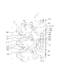
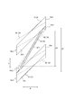
- FIG. 10 shows that the second lug 16 can be placed between the long lug 14 and the short lug 15 by using a rubber crawler extending linearly in a plan view on the outer circumference side of the crawler in an initial state before winding. It is explanatory drawing for demonstrating an example of the mechanism which can peel the clogged foreign material.
- the layout (arrangement configuration) of the first lug R1 and the second lug R2 on the outer peripheral surface of the crawler main body 11 is the same as in the other embodiments.
- symbol B ⁇ b> 1 is the base of the long lug 14
- symbol P ⁇ b> 1 is the top of the long lug 14.
- the base B1 and the top P1 of the long lug 14 are denoted by B1 (14) and P1 (14), respectively
- the base B1 and the top P1 of the short lug 15 are similarly denoted by B1 (15), respectively.
- P1 (15) the base and the top of the second lug 16 are denoted by reference sign B2 (16) and reference sign P2 (16), respectively.
- the extended end portions 14e1 and 14e2 of the long lug 14 are respectively the extended end portion of the top portion P1 (14) of the long lug 14 and the center of the base portion B1 (14) as an axis.
- the base B1 (14) has a shape that is shifted in the crawler circumferential direction in the opposite direction with respect to the extending end.
- the extended end part 14e1 of the long lug 14 has an inclined surface formed between the base part B1 (14) and the top part P1 (14).
- the extended end portions 14e1 and 14e2 of the short lug 15 are respectively extended with the extended end portion of the top portion P1 (15) about the center of the base portion B1 (15), and the extended end portion of the base portion B1 (15). It is shaped to be shifted in the crawler circumferential direction in the opposite direction with respect to the part.
- the inclined surface is formed between base B1 (15) and the top part P1 (15).
- the extended end portions 16e1 and 16e2 of the second lug 16 also have the extended end portion of the top portion P2 (16) thereof, respectively, with the center of the base B2 (16) as an axis.
- the base B2 (16) has a shape shifted in the crawler circumferential direction in the opposite direction with respect to the extending end.
- the long lug 14 and the short lug 15 and the second lug 16 are configured as described above, and one extended end 14e1 of the long lug 14 is connected to one extended end 16e1 of the second lug 16.
- the other extended end portion 16e2 of the second lug 16 is connected to the other extended end portion 15e2 of the short lug 15, the top portion P2 (16) of the second lug 16 is linear in a plan view of the crawler outer peripheral side.
- the long lug 14, the short lug 15 and the second lug 16 can be formed in a shape twisted around the extending direction axis of each lug.
- the circumferential length LP of the top portion P2 (16) of the second lug 16 is longer than the circumferential length LB of the base portion B2 (16) of the second lug 16.
- the second lug 16 is deformed following the bending of the crawler body 11 even if the second lug 16 extends linearly without changing the inclination angle of the second lug 16. By doing so, the foreign material clogged between the long lugs 14 and the short lugs 15 can be peeled off.
- the long lugs 14 and the short lugs 15 relating to the above-described elastic crawlers 1 to 3 project in a tapered manner from the outer peripheral surface 11f1 of the crawler main body 11, so that the crawler outer peripheral plan view is a crawler outer peripheral plan view.
- the second lug 16 having a shape twisted around the extending direction axis line is connected to the long lug 14 and the short lug 15 while the top portion P2 (16) of the second lug 16 extends linearly, the second lug
- the tread surface 16f1 of the second lug 16 can be deformed in a plan view of the crawler outer peripheral side even with the 16 extending straight.
- the amount of deformation of the second lug 16 is increased, and foreign substances clogged between the long lugs 14 and the short lugs 15 can be easily peeled off, so that the soil removal performance can be further improved.
- the extension length of the second lug R2 is increased, the amount of deformation of the second lug R2 increases when the elastic crawler 1 is wound around the rotating wheel while the vehicle is traveling, and the adjacent long lugs 14 and Since foreign substances clogged with the short lugs 15 can be easily peeled off, the soil removal performance can be further improved.
- FIG. 11A shows the rotation provided in the airframe for the elastic crawler 1 according to the first embodiment in which the protruding height of the second lug 16 is lower than the protruding heights of the long lug 14 and the short lug 15.
- FIG. 11B shows a model used for FEM analysis of the strain distribution generated when the ring is wound, and FIG. 11B shows the result of analysis using the model of FIG.
- FIG. 11 (a) shows a steady state before the elastic crawler 1 is wound around the rotating wheel
- FIG. 11 (b) shows a winding state after the elastic crawler 1 is wound around the rotating wheel.
- symbol ⁇ in FIG. 11B indicates distortion (deformation) generated in the second lug 16.
- FIG. 12A shows the rotation provided in the airframe for the elastic crawler 3 according to the third embodiment in which the protruding height of the second lug 16 is the same as the protruding height of the long lug 14 and the short lug 15.
- FIG. 12B shows a model used for FEM analysis of the strain distribution generated when it is wound on a ring, and FIG. 12B shows the result of analysis using the model of FIG. 12A. .
- FIG. 12 (a) shows a steady state before the elastic crawler 3 is wound around the rotating wheel
- FIG. 12 (b) shows a winding state after the elastic crawler 3 is wound around the rotating wheel.
- reference sign ⁇ in FIG. 12B indicates distortion (deformation) generated in the second lug 16.
- the distortion (deformation) generated in the second lug 16 is smaller than that of the elastic crawler 1. It is clear that the foreign matter clogged between the long lug 14 and the short lug 15 can be peeled off by the deformation of the second lug 16.
- the end portions 16e1 and 16e2 in the extending direction of the second lug 16 are respectively connected to the corresponding first lugs R1 arranged in the crawler circumferential direction. What is necessary is just to incline and extend with respect to the crawler circumferential direction and the crawler width direction between 1st lugs R1 adjacent to the crawler circumferential direction. That is, in the present invention, the end portions 16e1 and 16e2 in the extending direction of the second lugs 16 are connected to the corresponding first lugs R1 disposed in the crawler circumferential direction.
- the second lugs 16 that are not connected to the first lugs R1 include those formed intermittently between the first lugs R1 adjacent in the crawler circumferential direction.
- the second lugs 16 that are not connected to the first lugs R1 include individual lugs that are formed between the first lugs R1 that are adjacent in the crawler circumferential direction and are interrupted. Rugs included. Even if it is the 2nd lug 16 which is not connected with 1st lug R1 as mentioned above, the elastic crawler by which the soil removal property was improved can be obtained.
- the second lug 16 can be at least one lug disposed between the first lugs R1 adjacent in the crawler circumferential direction.
- the second lug 16 is connected to one of the two first lugs R1 arranged in the crawler circumferential direction. Most preferably, the second lug 16 is connected to each of the two first lugs R1 arranged in the crawler circumferential direction as in the above-described embodiments.
- 1st lug R1 was comprised with the different long lug 14 and the short lug 15, 1st lug R1 can be made into the 1st lug of the same shape.
- the first lugs R1 arranged on the outer side in the crawler width direction of the crawler main body 11 are arranged on the same line in the crawler width direction and are symmetrical with respect to the crawler width center line O. However, they can be staggered by shifting in the crawler circumferential direction, and the layout with respect to the crawler body 11 is not limited.
- the elastic crawler 1 is grounded at the lower side of the drawing and is rotated from the lower side to the upper side of the drawing.
- the elastic crawler 1 is grounded at the lower side of the drawing and from the upper side of the drawing. It can also be rotated downward. Further, in each of the embodiments described above, the elastic crawler has been described as an elastic crawler with a cored bar, but the elastic crawler according to the present embodiment includes a cored bar-less elastic crawler.
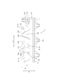
- FIG. 13 shows a part of the elastic crawler 4 according to the fourth embodiment of the present invention from the crawler outer peripheral surface side.
- components that are substantially the same as those of the elastic crawler according to the other embodiment have the same reference numerals, and a description thereof is omitted.
- the layout (arrangement configuration) of the first lug R1 and the second lug R2 on the outer peripheral surface of the crawler main body 11 is the same as in the other embodiments.
- the elastic crawler 4 is an elastic crawler that does not have a core metal 12 and does not have a core metal 12.
- the elastic crawler 4 has a protrusion 17 formed on the inner peripheral surface of the crawler main body portion 11 so as to protrude from the inner peripheral surface of the crawler main body portion 11. Yes.
- the protrusion 17 is engaged with, for example, a rotating wheel provided in the airframe, and drives the elastic crawler 4 by the rotation of the rotating wheel.
- the protrusions 17 are arranged at intervals in the crawler circumferential direction. As shown in FIG.
- the inflection point 16p of the second lug R2 is a region having a length L17 in which the protrusion 17 extends in the crawler circumferential direction in a plan view of the crawler outer peripheral side. It is preferable to arrange in the inside.
- the inflection point 16p of the second lug R2 is a crawler width direction view when the elastic crawler 4 is viewed in the direction of FIG.
- the protrusions 17 are preferably arranged in a region of length L17 extending in the crawler circumferential direction.
- the portion of the elastic crawler 4 in the region where the protrusions 17 extend in the crawler circumferential direction is the most difficult to bend when the elastic crawler 4 is wound, as viewed in the crawler width direction.
- the inflection point 16p is arrange
- the present invention can be used for an elastic crawler in which a plurality of lugs are formed on the outer peripheral surface of the crawler body at intervals in the crawler circumferential direction.
Landscapes
- Engineering & Computer Science (AREA)
- Chemical & Material Sciences (AREA)
- Combustion & Propulsion (AREA)
- Transportation (AREA)
- Mechanical Engineering (AREA)
- Tires In General (AREA)
- Toys (AREA)
Abstract
Description
この場合、排土性をより高めることができる。
14;長ラグ(第1ラグ), 14a;主踏面部, 14b;副踏面部, 14e1;主踏面部の一方の延在方向の端部, 14e2;主踏面部の他方の延在方向の端部, 14e3;副踏面部の他方の延在方向の端部, 14f1;主踏面部の踏面, 14f2;副踏面部の踏面, 15;短ラグ(第1ラグ), 15a;主踏面部, 15b;副踏面部, 15e1;主踏面部の一方の延在方向の端部, 15e2;主踏面部の他方の延在方向の端部, 15f1;主踏面部の踏面, 15f2;副踏面部の踏面, 16;第2ラグ, 16e1;第2ラグの一方の延在方向の端部(第2ラグの一方の延在方向の端部), 16e2;第2ラグの他方の延在方向の端部(第2ラグの他方の延在方向の端部), 16f1;第2ラグの頂面, 17:突起, D;クローラ厚み方向, e1:第2ラグとクローラ周方向で向かい合う、長ラグの主踏面部の根元部分, e2:第2ラグ16とクローラ周方向で向かい合う、短ラグの主踏面部の根元部分, L;クローラ周方向, L1;クローラ周方向, O;クローラ幅中心線, R1;第1ラグ, R2;第2ラグ, W;クローラ幅方向,w1;第1ラグの延在方向に直交する方向の第1ラグの幅,w2;第2ラグの延在方向に直交する方向の第2ラグの幅, θ1;第1ラグの延在方向とクローラ周方向とがなす角度, θ11:第2ラグとクローラ周方向で向かい合う、長ラグの主踏面部の根元部分の延在方向がクローラ周方向線となす角度, θ12:第2ラグとクローラ周方向で向かい合う、短ラグの主踏面部の根元部分の延在方向がクローラ周方向線となす角度, θ2;第2ラグの延在方向とクローラ周方向とがなす角度, θ21:第2ラグの一方の延在方向の端部付近の第2ラグの延在方向がクローラ周方向線となす角度, θ22:第2ラグの他方の延在方向の端部付近の第2ラグの延在方向がクローラ周方向線となす角度
Claims (10)
- 弾性体により無端帯状に形成されたクローラ本体部と、
前記クローラ本体部の外周面から突出して形成され、クローラ周方向に間隔をあけて設けられ、クローラ幅方向に延在する第1ラグと、
クローラ周方向に隣り合う前記第1ラグ同士の間の前記クローラ本体部の外周面から突出して形成され、クローラ周方向及びクローラ幅方向に対して傾斜して延在している、少なくとも1つの第2ラグと、
を備える、弾性クローラ。 - 前記第2ラグは、当該第2ラグの延在方向の少なくとも一方の端部が前記第1ラグに連結されている、請求項1に記載の弾性クローラ。
- 前記第2ラグは、延在方向の両端部が前記第1ラグに連結された、請求項1又は2に記載の弾性クローラ。
- 前記第2ラグは、該第2ラグの延在方向を変化させる変曲部を備える、請求項1乃至3のいずれか1項に記載の弾性クローラ。
- 前記第2ラグの前記クローラ本体部の外周面からの突出高さは、前記第1ラグの前記クローラ本体部の外周面からの突出高さよりも低い、請求項1乃至4のいずれか1項に記載の弾性クローラ。
- 前記第2ラグの延在方向に直交する方向の前記第2ラグの幅は、前記第1ラグの延在方向に直交する方向の前記第1ラグの幅よりも狭い、請求項1乃至5のいずれか1項に記載の弾性クローラ。
- 前記第2ラグの延在方向とクローラ周方向とがなす角度は、前記第2ラグの延在方向の少なくとも一部で、クローラ周方向に隣り合う第1ラグに近づくにしたがって小さくなる、請求項1乃至6のいずれか1項に記載の弾性クローラ。
- 前記第2ラグの延在方向とクローラ周方向とがなす角度は、前記第2ラグの延在方向の少なくとも一部で、クローラ周方向に隣り合う第1ラグに近づくにしたがって大きくなる、請求項1乃至7のいずれか1項に記載の弾性クローラ。
- 前記第2ラグの頂部は、前記弾性クローラを駆動する機体に備えられる回転輪に巻回された際に直線状に変形する、請求項1乃至8のいずれか1項に記載の弾性クローラ。
- 前記第1ラグは、クローラ幅方向外側から内側に向かうに従い、クローラ周方向一方側に傾斜して延在し、
前記第2ラグは、クローラ幅方向外側から内側に向かうに従い、前記クローラ周方向一方側に傾斜して延在する、請求項1乃至9のいずれか1項に記載の弾性クローラ。
Priority Applications (3)
| Application Number | Priority Date | Filing Date | Title |
|---|---|---|---|
| JP2017562930A JPWO2017126680A1 (ja) | 2016-01-22 | 2017-01-20 | 弾性クローラ |
| KR1020187020688A KR102062479B1 (ko) | 2016-01-22 | 2017-01-20 | 탄성 크롤러 |
| CN201780007666.1A CN108473171A (zh) | 2016-01-22 | 2017-01-20 | 弹性履带 |
Applications Claiming Priority (2)
| Application Number | Priority Date | Filing Date | Title |
|---|---|---|---|
| JP2016010949 | 2016-01-22 | ||
| JP2016-010949 | 2016-01-22 |
Publications (1)
| Publication Number | Publication Date |
|---|---|
| WO2017126680A1 true WO2017126680A1 (ja) | 2017-07-27 |
Family
ID=59361881
Family Applications (1)
| Application Number | Title | Priority Date | Filing Date |
|---|---|---|---|
| PCT/JP2017/001989 Ceased WO2017126680A1 (ja) | 2016-01-22 | 2017-01-20 | 弾性クローラ |
Country Status (4)
| Country | Link |
|---|---|
| JP (1) | JPWO2017126680A1 (ja) |
| KR (1) | KR102062479B1 (ja) |
| CN (1) | CN108473171A (ja) |
| WO (1) | WO2017126680A1 (ja) |
Citations (4)
| Publication number | Priority date | Publication date | Assignee | Title |
|---|---|---|---|---|
| JPS563084U (ja) * | 1979-06-20 | 1981-01-12 | ||
| JPH08113173A (ja) * | 1994-10-18 | 1996-05-07 | Bridgestone Corp | ゴムクロ−ラ |
| JP2008221885A (ja) * | 2007-03-08 | 2008-09-25 | Kubota Corp | ゴムクローラベルト |
| JP2012171502A (ja) * | 2011-02-22 | 2012-09-10 | Bridgestone Corp | 弾性クローラ |
Family Cites Families (6)
| Publication number | Priority date | Publication date | Assignee | Title |
|---|---|---|---|---|
| JPS5483235A (en) * | 1977-12-16 | 1979-07-03 | Bridgestone Corp | Elastic crawler track |
| CN2402576Y (zh) * | 1999-07-06 | 2000-10-25 | 芦晓民 | 适用于小节距推土机的履带板 |
| JP4262991B2 (ja) * | 2003-01-09 | 2009-05-13 | 株式会社ブリヂストン | ゴムクロ−ラ |
| JP4204354B2 (ja) * | 2003-03-06 | 2009-01-07 | 住友ゴム工業株式会社 | 弾性クローラ |
| JP4787660B2 (ja) | 2006-04-25 | 2011-10-05 | 株式会社ブリヂストン | ゴムクロ−ラ |
| JP4922017B2 (ja) * | 2007-03-06 | 2012-04-25 | 株式会社ブリヂストン | ゴムクローラ |
-
2017
- 2017-01-20 WO PCT/JP2017/001989 patent/WO2017126680A1/ja not_active Ceased
- 2017-01-20 JP JP2017562930A patent/JPWO2017126680A1/ja not_active Withdrawn
- 2017-01-20 KR KR1020187020688A patent/KR102062479B1/ko not_active Expired - Fee Related
- 2017-01-20 CN CN201780007666.1A patent/CN108473171A/zh active Pending
Patent Citations (4)
| Publication number | Priority date | Publication date | Assignee | Title |
|---|---|---|---|---|
| JPS563084U (ja) * | 1979-06-20 | 1981-01-12 | ||
| JPH08113173A (ja) * | 1994-10-18 | 1996-05-07 | Bridgestone Corp | ゴムクロ−ラ |
| JP2008221885A (ja) * | 2007-03-08 | 2008-09-25 | Kubota Corp | ゴムクローラベルト |
| JP2012171502A (ja) * | 2011-02-22 | 2012-09-10 | Bridgestone Corp | 弾性クローラ |
Also Published As
| Publication number | Publication date |
|---|---|
| JPWO2017126680A1 (ja) | 2018-11-15 |
| KR102062479B1 (ko) | 2020-01-03 |
| KR20180095057A (ko) | 2018-08-24 |
| CN108473171A (zh) | 2018-08-31 |
Similar Documents
| Publication | Publication Date | Title |
|---|---|---|
| JP4990396B2 (ja) | サイドウォール保護手段を備えたタイヤ | |
| JP5411627B2 (ja) | ゴムクローラ | |
| US7044567B2 (en) | Elastic endless crawler | |
| JP6359977B2 (ja) | 車両用空気入りタイヤ | |
| JP2005219567A (ja) | ゴムクローラ | |
| CN102686475B (zh) | 链轮和具有该链轮的橡胶履带组装体 | |
| CN107848589A (zh) | 弹性履带和弹性履带装置 | |
| JP2009248924A (ja) | ゴムクローラ | |
| JP5832791B2 (ja) | クローラ用芯金、弾性クローラ | |
| JP6934810B2 (ja) | ゴムクローラ | |
| WO2017126680A1 (ja) | 弾性クローラ | |
| JP2010120550A (ja) | 弾性クローラ | |
| JP6779583B2 (ja) | 弾性クローラ | |
| JP5785009B2 (ja) | タイヤ | |
| JP6799127B2 (ja) | 弾性クローラ | |
| JP6912973B2 (ja) | 空気入りタイヤ | |
| JP5753014B2 (ja) | タイヤ | |
| JP6758205B2 (ja) | 弾性クローラ | |
| JP6797743B2 (ja) | 弾性クローラ | |
| WO2016013287A1 (ja) | クローラ装置 | |
| JP7298332B2 (ja) | 弾性クローラ | |
| JP5348992B2 (ja) | 弾性履帯 | |
| JP7013436B2 (ja) | 弾性クローラ | |
| JP6805893B2 (ja) | 弾性クローラ | |
| CN110494348A (zh) | 弹性履带 |
Legal Events
| Date | Code | Title | Description |
|---|---|---|---|
| 121 | Ep: the epo has been informed by wipo that ep was designated in this application |
Ref document number: 17741557 Country of ref document: EP Kind code of ref document: A1 |
|
| ENP | Entry into the national phase |
Ref document number: 2017562930 Country of ref document: JP Kind code of ref document: A |
|
| ENP | Entry into the national phase |
Ref document number: 20187020688 Country of ref document: KR Kind code of ref document: A |
|
| WWE | Wipo information: entry into national phase |
Ref document number: 1020187020688 Country of ref document: KR |
|
| NENP | Non-entry into the national phase |
Ref country code: DE |
|
| 122 | Ep: pct application non-entry in european phase |
Ref document number: 17741557 Country of ref document: EP Kind code of ref document: A1 |