WO2017126572A1 - 熱可塑性樹脂フィルムの製造方法及び環状オレフィン樹脂フィルム - Google Patents
熱可塑性樹脂フィルムの製造方法及び環状オレフィン樹脂フィルム Download PDFInfo
- Publication number
- WO2017126572A1 WO2017126572A1 PCT/JP2017/001613 JP2017001613W WO2017126572A1 WO 2017126572 A1 WO2017126572 A1 WO 2017126572A1 JP 2017001613 W JP2017001613 W JP 2017001613W WO 2017126572 A1 WO2017126572 A1 WO 2017126572A1
- Authority
- WO
- WIPO (PCT)
- Prior art keywords
- resin
- screw
- film
- thermoplastic resin
- supply
- Prior art date
- Legal status (The legal status is an assumption and is not a legal conclusion. Google has not performed a legal analysis and makes no representation as to the accuracy of the status listed.)
- Ceased
Links
Images


Classifications
-
- B—PERFORMING OPERATIONS; TRANSPORTING
- B29—WORKING OF PLASTICS; WORKING OF SUBSTANCES IN A PLASTIC STATE IN GENERAL
- B29C—SHAPING OR JOINING OF PLASTICS; SHAPING OF MATERIAL IN A PLASTIC STATE, NOT OTHERWISE PROVIDED FOR; AFTER-TREATMENT OF THE SHAPED PRODUCTS, e.g. REPAIRING
- B29C48/00—Extrusion moulding, i.e. expressing the moulding material through a die or nozzle which imparts the desired form; Apparatus therefor
- B29C48/03—Extrusion moulding, i.e. expressing the moulding material through a die or nozzle which imparts the desired form; Apparatus therefor characterised by the shape of the extruded material at extrusion
- B29C48/07—Flat, e.g. panels
- B29C48/08—Flat, e.g. panels flexible, e.g. films
-
- B—PERFORMING OPERATIONS; TRANSPORTING
- B29—WORKING OF PLASTICS; WORKING OF SUBSTANCES IN A PLASTIC STATE IN GENERAL
- B29C—SHAPING OR JOINING OF PLASTICS; SHAPING OF MATERIAL IN A PLASTIC STATE, NOT OTHERWISE PROVIDED FOR; AFTER-TREATMENT OF THE SHAPED PRODUCTS, e.g. REPAIRING
- B29C48/00—Extrusion moulding, i.e. expressing the moulding material through a die or nozzle which imparts the desired form; Apparatus therefor
- B29C48/25—Component parts, details or accessories; Auxiliary operations
- B29C48/30—Extrusion nozzles or dies
-
- B—PERFORMING OPERATIONS; TRANSPORTING
- B29—WORKING OF PLASTICS; WORKING OF SUBSTANCES IN A PLASTIC STATE IN GENERAL
- B29C—SHAPING OR JOINING OF PLASTICS; SHAPING OF MATERIAL IN A PLASTIC STATE, NOT OTHERWISE PROVIDED FOR; AFTER-TREATMENT OF THE SHAPED PRODUCTS, e.g. REPAIRING
- B29C48/00—Extrusion moulding, i.e. expressing the moulding material through a die or nozzle which imparts the desired form; Apparatus therefor
- B29C48/25—Component parts, details or accessories; Auxiliary operations
- B29C48/30—Extrusion nozzles or dies
- B29C48/305—Extrusion nozzles or dies having a wide opening, e.g. for forming sheets
-
- B—PERFORMING OPERATIONS; TRANSPORTING
- B29—WORKING OF PLASTICS; WORKING OF SUBSTANCES IN A PLASTIC STATE IN GENERAL
- B29C—SHAPING OR JOINING OF PLASTICS; SHAPING OF MATERIAL IN A PLASTIC STATE, NOT OTHERWISE PROVIDED FOR; AFTER-TREATMENT OF THE SHAPED PRODUCTS, e.g. REPAIRING
- B29C48/00—Extrusion moulding, i.e. expressing the moulding material through a die or nozzle which imparts the desired form; Apparatus therefor
- B29C48/25—Component parts, details or accessories; Auxiliary operations
- B29C48/36—Means for plasticising or homogenising the moulding material or forcing it through the nozzle or die
- B29C48/395—Means for plasticising or homogenising the moulding material or forcing it through the nozzle or die using screws surrounded by a cooperating barrel, e.g. single screw extruders
- B29C48/40—Means for plasticising or homogenising the moulding material or forcing it through the nozzle or die using screws surrounded by a cooperating barrel, e.g. single screw extruders using two or more parallel screws or at least two parallel non-intermeshing screws, e.g. twin screw extruders
-
- B—PERFORMING OPERATIONS; TRANSPORTING
- B29—WORKING OF PLASTICS; WORKING OF SUBSTANCES IN A PLASTIC STATE IN GENERAL
- B29C—SHAPING OR JOINING OF PLASTICS; SHAPING OF MATERIAL IN A PLASTIC STATE, NOT OTHERWISE PROVIDED FOR; AFTER-TREATMENT OF THE SHAPED PRODUCTS, e.g. REPAIRING
- B29C48/00—Extrusion moulding, i.e. expressing the moulding material through a die or nozzle which imparts the desired form; Apparatus therefor
- B29C48/25—Component parts, details or accessories; Auxiliary operations
- B29C48/78—Thermal treatment of the extrusion moulding material or of preformed parts or layers, e.g. by heating or cooling
- B29C48/80—Thermal treatment of the extrusion moulding material or of preformed parts or layers, e.g. by heating or cooling at the plasticising zone, e.g. by heating cylinders
- B29C48/82—Cooling
-
- B—PERFORMING OPERATIONS; TRANSPORTING
- B29—WORKING OF PLASTICS; WORKING OF SUBSTANCES IN A PLASTIC STATE IN GENERAL
- B29C—SHAPING OR JOINING OF PLASTICS; SHAPING OF MATERIAL IN A PLASTIC STATE, NOT OTHERWISE PROVIDED FOR; AFTER-TREATMENT OF THE SHAPED PRODUCTS, e.g. REPAIRING
- B29C48/00—Extrusion moulding, i.e. expressing the moulding material through a die or nozzle which imparts the desired form; Apparatus therefor
- B29C48/25—Component parts, details or accessories; Auxiliary operations
- B29C48/78—Thermal treatment of the extrusion moulding material or of preformed parts or layers, e.g. by heating or cooling
- B29C48/80—Thermal treatment of the extrusion moulding material or of preformed parts or layers, e.g. by heating or cooling at the plasticising zone, e.g. by heating cylinders
- B29C48/83—Heating or cooling the cylinders
-
- B—PERFORMING OPERATIONS; TRANSPORTING
- B29—WORKING OF PLASTICS; WORKING OF SUBSTANCES IN A PLASTIC STATE IN GENERAL
- B29C—SHAPING OR JOINING OF PLASTICS; SHAPING OF MATERIAL IN A PLASTIC STATE, NOT OTHERWISE PROVIDED FOR; AFTER-TREATMENT OF THE SHAPED PRODUCTS, e.g. REPAIRING
- B29C48/00—Extrusion moulding, i.e. expressing the moulding material through a die or nozzle which imparts the desired form; Apparatus therefor
- B29C48/25—Component parts, details or accessories; Auxiliary operations
- B29C48/78—Thermal treatment of the extrusion moulding material or of preformed parts or layers, e.g. by heating or cooling
- B29C48/80—Thermal treatment of the extrusion moulding material or of preformed parts or layers, e.g. by heating or cooling at the plasticising zone, e.g. by heating cylinders
- B29C48/84—Thermal treatment of the extrusion moulding material or of preformed parts or layers, e.g. by heating or cooling at the plasticising zone, e.g. by heating cylinders by heating or cooling the feeding screws
-
- B—PERFORMING OPERATIONS; TRANSPORTING
- B29—WORKING OF PLASTICS; WORKING OF SUBSTANCES IN A PLASTIC STATE IN GENERAL
- B29C—SHAPING OR JOINING OF PLASTICS; SHAPING OF MATERIAL IN A PLASTIC STATE, NOT OTHERWISE PROVIDED FOR; AFTER-TREATMENT OF THE SHAPED PRODUCTS, e.g. REPAIRING
- B29C48/00—Extrusion moulding, i.e. expressing the moulding material through a die or nozzle which imparts the desired form; Apparatus therefor
- B29C48/25—Component parts, details or accessories; Auxiliary operations
- B29C48/92—Measuring, controlling or regulating
-
- B—PERFORMING OPERATIONS; TRANSPORTING
- B29—WORKING OF PLASTICS; WORKING OF SUBSTANCES IN A PLASTIC STATE IN GENERAL
- B29C—SHAPING OR JOINING OF PLASTICS; SHAPING OF MATERIAL IN A PLASTIC STATE, NOT OTHERWISE PROVIDED FOR; AFTER-TREATMENT OF THE SHAPED PRODUCTS, e.g. REPAIRING
- B29C2948/00—Indexing scheme relating to extrusion moulding
- B29C2948/92—Measuring, controlling or regulating
- B29C2948/92323—Location or phase of measurement
- B29C2948/92361—Extrusion unit
- B29C2948/92409—Die; Nozzle zone
-
- B—PERFORMING OPERATIONS; TRANSPORTING
- B29—WORKING OF PLASTICS; WORKING OF SUBSTANCES IN A PLASTIC STATE IN GENERAL
- B29C—SHAPING OR JOINING OF PLASTICS; SHAPING OF MATERIAL IN A PLASTIC STATE, NOT OTHERWISE PROVIDED FOR; AFTER-TREATMENT OF THE SHAPED PRODUCTS, e.g. REPAIRING
- B29C2948/00—Indexing scheme relating to extrusion moulding
- B29C2948/92—Measuring, controlling or regulating
- B29C2948/92323—Location or phase of measurement
- B29C2948/92476—Fluids, e.g. for temperature control or of environment
Definitions
- This disclosure relates to a method for producing a thermoplastic resin film and a cyclic olefin resin film.
- Thermoplastic resin films are used in various applications such as optical films and solar cell back surface protective films.
- a cellulose resin film such as a cellulose acylate film is used as an optical film used for a liquid crystal display device or the like.
- a cellulose resin film such as a cellulose acylate film is formed by melting a cellulose resin with an extruder and extruding the cellulose resin into a die, discharging the molten resin into a sheet from the die, and solidifying by cooling.
- a cyclic olefin resin film has attracted attention as a film having a small change in optical properties with respect to changes in environmental temperature and humidity, and it has been studied to melt the cyclic olefin resin and use it as a film for polarizing plates and liquid crystal displays. ing.
- the resin When a thermoplastic resin film is produced by the melt extrusion method, the resin may be thermally oxidized and deteriorated to generate foreign matter (hereinafter, sometimes referred to as “thermally deteriorated foreign matter”).
- thermally deteriorated foreign matter In particular, in the case of an optical film, the foreign matter contained in the film becomes a point defect, which has a great influence on the quality of the optical film, such as a decrease in light transmission due to the point defect and an increase in unevenness.
- the oxygen concentration at the opening of an extruder used for melt film formation is set to 10 ppm or less in an inert gas atmosphere. Thus, it is disclosed that thermal oxidation deterioration of the resin is suppressed.
- An object of one embodiment of the present invention is to provide a method for producing a thermoplastic resin film capable of producing a thermoplastic resin film by suppressing the generation of heat-degraded foreign matter without performing extensive atmosphere replacement.
- the subject of another embodiment of this invention is providing the cyclic olefin resin film with high light transmittance.
- the present disclosure includes the following embodiments. ⁇ 1> A cylinder having a supply port to which the raw material resin is supplied and an extrusion port from which the molten resin in which the raw material resin is melted is extruded, a screw shaft and a flight spirally arranged around the screw shaft, A supply part resin calculated by the following formula using an extruder having a supply part, a compression part and a metering part in order from the supply port side along the screw axis in the cylinder. The process of supplying and melting the raw material resin under the condition that the transport efficiency satisfies 0.75 ⁇ supply part resin transport efficiency ⁇ 1.0, and melt-extruding the molten resin extruded from the extrusion port into a film form from the die. A method for producing a thermoplastic resin film.
- W Screw flight interval (mm) in the supply section Hf: Groove depth in the supply section (mm)
- D Inner diameter of cylinder (mm)
- ⁇ Screw flight angle (°) in the supply section
- Q Extrusion amount of molten resin (kg / h)
- ⁇ Specific gravity of raw resin (g / cm 3 )
- N Number of screw rotations per minute (rpm)
- Compression ratio Volume per pitch of screw flights in the supply section / Volume per pitch of screw flights in the measuring section
- thermoplastic resin film according to ⁇ 1>, wherein the oxygen concentration in the supply port is 0.1% or less.
- the temperature of the raw material resin supplied into the cylinder from the supply port is Tg ⁇ 90 ° C. or more and Tg + 10 ° C. or less ⁇ 1> or ⁇ 2>
- ⁇ 4> The method for producing a thermoplastic resin film according to any one of ⁇ 1> to ⁇ 3>, wherein the raw material resin is supplied into the cylinder from the supply port through a vacuum hopper.
- thermoplastic resin film according to any one of ⁇ 1> to ⁇ 4>, wherein the screw is a double flight screw.
- the temperature of the screw in the supply unit is controlled to any one of ⁇ 1> to ⁇ 5>, which is Tg ⁇ 80 ° C. or higher and Tg ° C. or lower.
- ⁇ 7> The method for producing a thermoplastic resin film according to any one of ⁇ 1> to ⁇ 6>, wherein the raw material resin is a cyclic olefin resin.
- the number of foreign matters having a longest diameter of 30 ⁇ m or more is 0.3 pieces / cm 2 or less per 100 ⁇ m thickness, and the number of foreign matters having a longest diameter of 5 ⁇ m or more and less than 30 ⁇ m is 100 pieces / cm 2 or less.
- Olefin resin film is 0.3 pieces / cm 2 or less per 100 ⁇ m thickness, and the number of foreign matters having a longest diameter of 5 ⁇ m or more and less than 30 ⁇ m is 100 pieces / cm 2 or less.
- thermoplastic resin film capable of producing a thermoplastic resin film while suppressing the occurrence of heat-degraded foreign matter without performing extensive atmosphere replacement.
- a cyclic olefin resin film with high light transmittance is provided.
- FIG. 1 is a schematic diagram illustrating an example of the overall configuration of an apparatus for carrying out the method for producing a thermoplastic resin film of the present disclosure.
- FIG. 2 is a schematic diagram illustrating an example of a configuration of an extruder that can be used in the manufacturing method of the present disclosure.
- FIG. 3 is an enlarged schematic view showing a supply section of the extruder shown in FIG.
- thermoplastic resin film and a cyclic olefin resin film of the present disclosure will be specifically described with reference to the accompanying drawings.
- reference numerals may be omitted.
- ⁇ representing a numerical range means a range including numerical values described as the lower limit value and the upper limit value before and after that, and when only the upper limit value or the lower limit value is attached with a unit. , Meaning the same unit throughout the numerical range.
- process is not only an independent process, but is included in this term if the intended purpose of the process is achieved even when it cannot be clearly distinguished from other processes.
- (co) polymer means either or both of a homopolymer and a copolymer containing a specific repeating unit.
- the upper limit value or lower limit value described in a numerical range may be replaced with the upper limit value or lower limit value of the numerical range described in other steps.
- the upper limit value or the lower limit value described in a certain numerical range may be replaced with the values shown in the examples.
- a method for producing a thermoplastic resin film of the present disclosure includes a supply port to which a raw material resin is supplied and an extrusion port from which a molten resin in which the raw material resin is melted is extruded.
- a cylinder, a screw shaft and a screw spirally arranged around the screw shaft, and a screw that rotates in the cylinder, and the supply unit in order from the supply port side along the screw shaft in the cylinder Using a extruder having a compression part and a metering part, supply and melting of the raw material resin under the condition that the supply part resin transport efficiency calculated by the following formula satisfies 0.75 ⁇ supply part resin transport efficiency ⁇ 1.0 And a step of melt-extruding the molten resin extruded from the extrusion port into a film shape from the die.
- the “raw resin” means a resin composition containing not only a resin component but also an additive added as necessary.
- the thermoplastic resin may be referred to as “resin”, and the thermoplastic resin film may be referred to as “film”.
- FIG. 1 schematically shows an example of the entire configuration of a film forming apparatus (thermoplastic resin film manufacturing apparatus) for carrying out the method for manufacturing a thermoplastic resin film of the present disclosure.
- a film forming apparatus 10 shown in FIG. 1 includes a hopper 12 into which a thermoplastic resin as a raw material resin is charged, an extruder 14 for melting the thermoplastic resin supplied from the hopper 12, and a molten resin (molten resin).
- a gear pump 16 that stabilizes the extrusion amount, a filter 18 that filters the molten resin, a die 20 that melt-extrudes the molten resin into a film, and a plurality of coolings that cool the high-temperature thermoplastic resin discharged from the die 20 in multiple stages.
- Contact rolls that sandwich the thermoplastic resin 100 discharged from the rolls (hereinafter, the cooling rolls may be referred to as casting rolls) 22, 24, 26 and the die 20 with the first cooling rolls 22. Is sometimes referred to as a touch roll) 28.
- a peeling roll for peeling the thermoplastic resin film 100 from the last third cooling roll 26 and a winder for winding the cooled film are provided.
- FIG. 2 schematically shows an example of the configuration of an extruder that can be used in the production method of the present disclosure.
- the extruder 14 includes a cylinder 44 and a screw 50 disposed in the cylinder.
- the cylinder 44 has a supply port 52 to which a thermoplastic resin is supplied and an extrusion port 54 to which a molten resin in which the thermoplastic resin is melted is extruded.
- the inside of the cylinder 44 is along the screw shaft 46 along the supply port 52 side.
- a supply part region indicated by A in FIG. 2 for transporting the thermoplastic resin supplied from the supply port 52 while preheating
- a compression part in FIG. 2 for kneading and melting the thermoplastic resin while compressing.
- FIG. 3 is an enlarged schematic view of the supply section A of the extruder 14. Further, the hopper 12 shown in FIG. 1 is attached to the supply port 52 of the cylinder 44 shown in FIG.
- the screw 50 has a screw shaft 46 and a flight (hereinafter also referred to as a screw flight) 48 arranged in a spiral shape around the screw shaft 46 and is rotated in a cylinder 44 by a motor (not shown). Has been.
- a temperature control means (such as a heater) arranged around the cylinder 44 in a longitudinal direction, for example, divided into 3 to 20 is provided. It is preferable to provide it.
- thermoplastic resin film manufacturing apparatus 10 When an extruder 14 having the configuration shown in FIG. 2 is provided and a thermoplastic resin film is manufactured by the thermoplastic resin film manufacturing apparatus 10 having the configuration shown in FIG. 1, a thermoplastic resin as a raw material resin is introduced into the hopper 12. The gas is supplied into the cylinder 44 through the supply port 52 of the cylinder 44. The thermoplastic resin supplied from the supply port 52 into the cylinder 44 is transported toward the extrusion port 54 while being preheated in the supply part A by the rotation of the screw 50.
- the thermoplastic resin preheated in the supply part A is transported to the compression part B.
- the compression part B has a configuration in which the diameter of the screw shaft 46 gradually increases toward the extrusion port 54, and the thermoplastic resin is transferred between the inner wall of the cylinder 44 and the screw 50 along with the transport in the compression part B.
- the mixture is kneaded while being compressed, and is heated and brought into contact with the temperature-controlled cylinder 44 to melt.
- the resin melted in the compression unit B is transported to the metering unit C, and the metering unit C measures the molten resin, and the amount of extrusion from the extrusion port 54 is stabilized.
- the molten resin melted by the extruder 14 and extruded from the extrusion port 54 is continuously fed toward the die 20 through the pipe 40 through the gear pump 16 and the filter 18.
- the molten resin is melt extruded from the die 20 into a film.
- a thermoplastic resin 100 extruded into a film is shown in FIG.
- the film-like thermoplastic resin melt-extruded from the die 20 is sandwiched between the contact roll (touch roll) 28 and the first cooling roll 22, passed through the second cooling roll 24 and the third cooling roll 26, It is wound up by the illustrated winder.
- thermoplastic resin film of the present disclosure when the thermoplastic resin film is manufactured through the steps as described above, the supply part resin transport efficiency calculated by the above-described formula is 0.75 ⁇ supply part resin transport.
- the thermoplastic resin is supplied and melted under a condition satisfying efficiency ⁇ 1.0, and the resin melted by the extruder is melt-extruded from the die into a film.
- the reason why generation of thermally deteriorated foreign matter is suppressed in the film obtained by the method for producing a thermoplastic resin film of the present disclosure is estimated as follows.
- the fractional molecule “Q / N” in the first term means the amount of molten resin extruded per screw rotation in the melt extrusion process.
- the denominator means the theoretical transport amount in the supply section in the cylinder, and it means that the theoretical transport amount is divided by the compression ratio so that it can be transported with high efficiency regardless of the compression ratio.
- (D / 90) 0.5 is a correction coefficient for the cylinder inner diameter.
- the supply resin transport efficiency calculated by the formula of the supply resin transport efficiency in the present disclosure is 0.75 or more, that is, the solid resin transport efficiency before melting in the extruder supply unit is increased, and the original resin density
- melt extrusion can be performed by setting the resin transport efficiency of the supply section to 1.0 or less. Therefore, it is considered that a thermoplastic resin film in which the generation of heat-deteriorated foreign matter generated by the reaction between the resin and oxygen in the obtained film is suppressed can be produced without requiring a large atmosphere replacement.
- thermoplastic resin film of the present disclosure will be described more specifically.
- the example which manufactures a cyclic olefin resin film suitably using cyclic olefin resin as raw material resin is demonstrated.
- the method for producing a thermoplastic resin film of the present disclosure is not limited to the method for producing a cyclic olefin resin film described below, and is also suitable for producing a thermoplastic resin film using a thermoplastic resin other than the cyclic olefin resin. Can be applied to.
- the raw material resin used in the present disclosure is not particularly limited as long as it is a thermoplastic resin, and may be selected according to the application of the film to be produced.
- an acrylic resin, a methacrylic resin, a polycarbonate (PC) resin, or a cyclic olefin resin is preferably used as the thermoplastic resin from the viewpoint of good transparency of the resulting film. Can do.
- cyclic olefin resins are preferred.
- the cyclic olefin resin is a (co) polymer resin having a cyclic olefin structure.
- Examples of the polymer resin having a cyclic olefin structure include (1) a norbornene-based polymer and (2) a monocyclic cyclic olefin polymer. And (3) a polymer of a cyclic conjugated diene, (4) a vinyl alicyclic hydrocarbon polymer, and hydrides of (1) to (4).
- a norbornene polymer and (2) a polymer of a monocyclic olefin and a hydride thereof are preferable.
- the norbornene-type polymer in this specification is used by the meaning containing the homopolymer and the copolymer containing the repeating unit which has a norbornene structure, and a ring-opening may be sufficient as a norbornene structure.
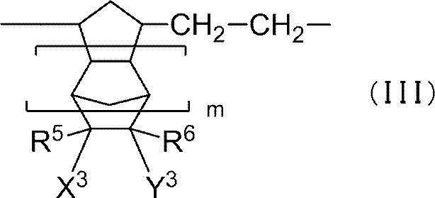
- a ring-opening (co) polymer containing at least one cyclic repeating unit represented by the general formula (III) can also be suitably used.
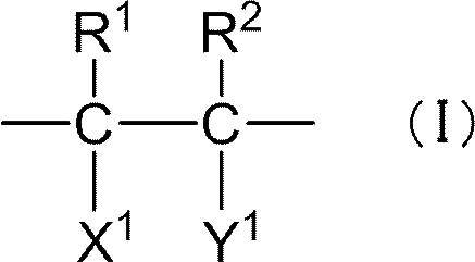
- R 1 , R 2 , R 3 , R 4 , R 5 , and R 6 each independently represent a hydrogen atom or a hydrocarbon group having 1 to 10 carbon atoms
- X 1 , X 2 , X 3 , Y 1 , Y 2 and Y 3 are each independently a hydrogen atom, a hydrocarbon group having 1 to 10 carbon atoms, a halogen atom, a hydrocarbon group having 1 to 10 carbon atoms substituted with a halogen atom, — (CH 2 ) n COOR 11 , — (CH 2 ) n OCOR 12 , — (CH 2 ) n NCO, — (CH 2 ) n NO 2 , — (CH 2 ) n CN, — (CH 2 ) n CONR 13 R 14 , — (CH 2 ) n (—CO) 2 O composed of
- R 11 , R 12 , R 13 , R 14 , and R 15 represent a hydrogen atom or a hydrocarbon group having 1 to 20 carbon atoms
- Z represents a hydrocarbon group or a hydrocarbon group substituted with halogen
- W represents SiR 16 p D 3-p
- R 16 represents a hydrocarbon group having 1 to 10 carbon atoms
- D represents a halogen atom
- p is an integer of 0 to 3
- N represents an integer of 0 to 10.
- the retardation in the thickness direction (Rth) of the optical film is reduced. It is possible to increase the expression of in-plane retardation (Re).
- the functional group having a large polarizability means a functional group containing two or more types of atoms having different electronegativity and having a dipole moment.
- functional groups having a large degree of polarity include, for example, a carboxy group, a carbonyl group, an epoxy group, an ether group, a hydroxy group, an amino group, an imino group, a cyano group, an amide group, an imide group, an ester group, and a sulfone group.
- Norbornene-based addition (co) polymers are disclosed in JP-A-10-7732, JP-T 2002-504184, US Patent Publication US2004 / 229157A1, International Publication WO2004 / 070463A1, and the like.
- the norbornene-based addition (co) polymer is obtained, for example, by addition polymerization of norbornene-based polycyclic unsaturated compounds.
- a norbornene-based addition (co) polymer includes, if necessary, a norbornene-based polycyclic unsaturated compound, ethylene, propylene, butene; conjugated dienes such as butadiene and isoprene; non-conjugated dienes such as ethylidene norbornene; acrylonitrile It can also be obtained by addition polymerization with linear diene compounds such as acrylic acid, methacrylic acid, maleic anhydride, acrylic acid ester, methacrylic acid ester, maleimide, vinyl acetate, and vinyl chloride. A commercially available product may be used as the norbornene-based addition (co) polymer.
- the norbornene-based addition (co) polymer is commercially available from Mitsui Chemicals, Inc. under the name of Apel (registered trademark), and has a different glass transition temperature (Tg), such as APL8008T (Tg: 70 ° C.), APL6013T ( Grades such as Tg: 125 ° C) and APL6015T (Tg: 145 ° C).
- Tg glass transition temperature
- Norbornene-based addition (co) polymers such as TOPAS 8007, 6013, and 6015 are commercially available as pellets from Polyplastics.
- Appear 3000 is commercially available as a norbornene addition (co) polymer from Ferrania.
- a hydride of a norbornene-based polymer can be obtained by subjecting a polycyclic unsaturated compound to addition polymerization or metathesis ring-opening polymerization and then hydrogenation.
- Examples of hydrides of norbornene polymers include, for example, JP-A-1-240517, JP-A-7-196636, JP-A-60-26024, JP-A-62-19801, JP-A-2003-159767, and JP-A-2003-159767. No. 2004-309979 and the like, and the description thereof can be referred to in the present disclosure.
- the norbornene-based polymer used in the production method of the present disclosure is preferably a polymer containing a cyclic repeating unit represented by the general formula (III).
- R 5 and R 6 is preferably a hydrogen atom or -CH 3
- X 3 and Y 3 is a hydrogen atom, it is -Cl or -COOCH 3 preferably, the other groups are selected appropriately.
- Norbornene-based resins are commercially available from JSR Corporation under the trade name Arton (registered trademark) G or Arton F, and from Zeon Corporation, Zeonor (registered trademark) ZF14, ZF16, Zeonex (Zeonex). : Registered trademark) 250 or ZEONEX 280, which are commercially available, and these can be used.
- various additives according to the use of the film to be produced, such as a deterioration inhibitor, an ultraviolet ray inhibitor, a retardation (optical anisotropy) modifier, fine particles, a peeling accelerator, An infrared absorber or the like can be used.
- the additive may be solid or oily.
- ⁇ indicates the specific gravity (g / cm 3 ) of the raw material resin (thermoplastic resin), and the supply part is in accordance with the specific gravity ⁇ of the resin used.
- Other parameters of resin transport efficiency may be set.
- thermoplastic resin as the raw material resin and the additive added as necessary are mixed in advance and pelletized prior to melt film formation. It is preferable to dry the thermoplastic resin in advance for pelletization. When using a solid additive, it is preferable to dry the additive in advance.
- a drying method and drying conditions are not particularly limited. Examples of the drying method include a method of heating in a heating furnace at a temperature of 80 ° C. to 110 ° C., preferably around 90 ° C., for a heating time of 8 hours or longer, preferably 8 hours to 12 hours. This is not the case.
- the heating temperature and heating time for drying the thermoplastic resin may be selected in consideration of at least one of the glass transition temperature Tg and melting point of the thermoplastic resin.
- the additive has fluidity such as an oily substance, it may be put into the extruder as it is and mixed with the thermoplastic resin in the extruder.
- thermoplastic resin for example, by using a vent type extruder, drying of the thermoplastic resin, which is preferably performed in advance, can be omitted.
- Additives added as necessary when pelletizing the thermoplastic resin are not mixed with the thermoplastic resin in advance, but are added from the raw material inlet or vent port in the middle of the extruder used for pelletization You can also
- the size of the pellet is, for example, preferably a cross-sectional area of 1 mm 2 to 300 mm 2 and a length of 1 mm to 30 mm, more preferably a cross-sectional area of 2 mm 2 to 100 mm 2 and a length of 1.5 mm to 10 mm.
- the method for drying the pellet is not particularly limited as long as the desired moisture content can be obtained. Usually, drying using a dehumidifying air dryer is often performed. It is preferable to efficiently dry the pellets by using means such as heating, blowing, decompressing, stirring, etc. alone or in combination. In addition, it is preferable to use a dry hopper for supplying the raw material resin, and it is preferable that the dry hopper to be used has a heat insulating structure.
- the drying temperature for drying the pellets is preferably 0 ° C. to 200 ° C., more preferably 40 ° C. to 180 ° C., and particularly preferably 60 ° C. to 150 ° C.
- the water content of the thermoplastic resin used as the raw material resin is preferably 1.0% by mass or less, more preferably 0.1% by mass or less, and further preferably 0.01% by mass or less.
- Raw material resin is put into the hopper 12 and supplied into the cylinder 44 from the supply port 52 of the cylinder 44.
- the raw material resin charged into the hopper 12 may be a thermoplastic resin pellet, a pellet containing a thermoplastic resin and an additive, or a flaky thermoplastic resin.
- the oxygen concentration at the supply port 52 is preferably low, and specifically, it is preferably 0.1% or less on a volume basis.
- Examples of a method for reducing the oxygen concentration at the supply port 52 include a method of supplying a raw material resin into the cylinder 44 from the supply port 52 through a vacuum hopper, and a method of supplying nitrogen gas to the supply port 52 of the cylinder 44.
- the oxygen concentration at the supply port 52 can be measured by providing a pipe (not shown) at the supply port 52 and connecting an oxygen concentration meter (not shown).
- D indicates the inner diameter (mm) of the cylinder 44.
- the inner diameter D of the cylinder 44 is preferably 10 mm to 300 mm, and more preferably 20 mm to 250 mm, from the viewpoint of carrying out melt extrusion by setting the resin transport efficiency of the supply section to 0.75 or more and 1.0 or less.
- the resin supplied into the cylinder 44 is gradually heated by friction caused by the rotation of the screw 50 and temperature control means (not shown) arranged around the cylinder 44. From the viewpoint of supplying the raw material resin from the supply port 52 and quickly melting the thermoplastic resin in the cylinder 44, it is preferable that the thermoplastic resin is supplied from the supply port in a heated state.
- the temperature of the thermoplastic resin supplied from the supply port 52 into the cylinder 44 is preferably Tg ⁇ 90 ° C. or higher and Tg + 10 ° C. or lower. More preferably, the temperature is controlled to -80 ° C or higher and Tg-10 ° C or lower.
- thermoplastic resin supplied into the cylinder 44 from the supply port 52 As a method of controlling the temperature of the thermoplastic resin supplied into the cylinder 44 from the supply port 52 to the above preferable range, a method of preheating pellets to be put into the hopper, a method using a hopper equipped with a heating means, In addition to the hopper, there may be mentioned a method of providing a heating means in the vicinity of the supply port.
- the thermoplastic resin supplied from the supply port 52 into the cylinder 44 is transported toward the extrusion port 54 while being preheated in the supply part A by the rotation of the screw 50.
- W indicates the flight interval (mm) of the screw 50 in the supply part in the cylinder.
- the screw flight interval W is preferably 10 mm to 300 mm, and more preferably 20 mm to 250 mm, from the viewpoint of carrying out melt extrusion by setting the resin transport efficiency of the supply section to 0.75 or more and 1.0 or less.
- ⁇ indicates the screw flight angle (°) in the supply part A.
- the screw flight angle ⁇ in the supply part A is preferably 5 ° to 30 °, more preferably 10 ° to 25 °, from the viewpoint of carrying out melt extrusion with a supply part resin transport efficiency of 0.75 to 1.0. .
- a full flight, a double flight, etc. can be used for the flight on the screw.
- a double flight screw is preferable.
- the double flight screw is a screw in which two flights are spirally arranged on the screw shaft in the compression section B.
- Hf is the groove depth (mm) in the supply part A, that is, the screw shaft radial direction from the outer peripheral surface of the screw shaft in the supply part A to the outer periphery of the screw flight.
- the distance hereinafter may be referred to as “supply section groove depth”.
- the supply section groove depth Hf is preferably 2 mm to 30 mm, and more preferably 3 mm to 25 mm from the viewpoint of carrying out melt extrusion with a supply section resin transport efficiency of 0.75 to 1.0.
- the supply section groove depth can be adjusted by the inner diameter D of the cylinder 44, the outer diameter d1 of the screw shaft in the supply section, and the height of the screw flight 48.
- N indicates the screw rotation speed (rpm: rotation / min).
- the screw rotation speed (rpm) in the production method of the present disclosure is preferably 3 rpm to 150 rpm, and more preferably 5 rpm to 100 rpm.
- the glass transition temperature of the thermoplastic resin is Tg (° C.)
- Tg glass transition temperature
- the temperature of the screw 50 is set higher than Tg and is set to a temperature at which the raw material resin is softened by the supply unit A, the frictional force of the resin against the screw 50 and There is a possibility that the difference in the frictional force of the resin with respect to the cylinder 44 becomes small and it is difficult to proceed to the compression part B where the resin is melted.
- the temperature of the screw can be controlled with high accuracy by using a screw having a structure that circulates and supplies a heat medium inside the screw shaft.
- the compression ratio indicates “volume per screw flight pitch in the supply unit / volume per screw flight pitch in the metering unit”. The compression ratio is calculated using the outer diameter d1 of the screw shaft of the supply unit A, the outer diameter d2 of the screw shaft of the measuring unit C, the groove depth Hf of the supplying unit A, and the groove depth Hm of the measuring unit C.
- the compression ratio is too small, the thermoplastic resin is not sufficiently melt-kneaded, an undissolved portion is generated, undissolved foreign matter tends to remain in the manufactured thermoplastic film, and air bubbles are easily mixed. As a result, the strength of the thermoplastic film may decrease, or the film may be easily broken when it is stretched, and the orientation may not be sufficiently increased.
- the compression ratio is too large, the shear stress applied to the thermoplastic resin becomes too large and the resin is likely to deteriorate due to heat generation, so that there is a possibility that a yellowish color is likely to appear on the thermoplastic film after production.
- the compression ratio is preferably 1.5 to 4.0, more preferably 2.0 to 3.5, from the above viewpoint and from the viewpoint of carrying out melt extrusion with the resin transport efficiency of the supply section being 0.75 or more and 1.0 or less. preferable.
- the compression ratio is adjusted by adjusting at least one of the inner diameter D of the cylinder 44, the outer diameters d1 and d2 of the screw shafts in the supply unit and the metering unit, the flight interval W of the screw 50, and the flight angle ⁇ . Can do.
- L / D is preferably 20 to 70.
- L / D is the ratio of the cylinder length L to the cylinder inner diameter D.
- the extrusion temperature is preferably set to 200 ° C to 300 ° C.
- the set temperature in the extruder may be the same temperature in the entire region, or may have a different temperature distribution depending on the region. It is preferable that the temperature distribution is different depending on the region. In particular, it is more preferable that the temperature of the supply unit A described above is higher than the temperature of the compression unit B in the extruder.
- L / D is preferably in the range of 20 to 70, more preferably in the range of 22 to 60, and still more preferably in the range of 24 to 50.
- the molten resin is extruded from the extrusion port 54 of the cylinder 44 through the measuring section C.
- the molten resin is measured, and the extrusion amount from the extrusion port 54 is stabilized.
- the molten resin extruded from the extruder 14 is transported toward the die 20 through the pipe 40, but it is preferable to perform a so-called breaker plate type filtration in which a filter medium is provided at the outlet of the extruder 14.
- the molten resin extruded from the extruder 14 is preferably transported to the die 20 via the gear pump 16 and the filter 18.
- the molten resin may be referred to as “melt”.
- gear pump 16 In order to improve the thickness accuracy of the film, it is important to keep the variation in the discharge amount of the molten resin extruded from the extruder 14 low. From the viewpoint of further reducing fluctuations in the discharge amount, it is preferable to provide a gear pump 16 between the extruder 14 and the die 20 and supply a certain amount of molten resin from the gear pump 16.
- the gear pump is accommodated in a state in which a pair of gears composed of a drive gear and a driven gear mesh with each other, and the drive gear is driven to engage and rotate the two gears so that the gear pump is melted from the suction port formed in the housing. Resin is sucked into the cavity, and a certain amount of resin is discharged from a discharge port also formed in the housing.
- the filter 18 is preferably a filtration device incorporating a so-called leaf type disk filter. Filtration of the thermoplastic resin discharged from the extruder may be filtration performed by providing one filtration unit, or multistage filtration performed by providing a plurality of filtration units. It is preferable that the filtration accuracy of the filter medium is higher. However, the filtration accuracy is preferably 15 ⁇ m to 3 ⁇ m and more preferably 10 ⁇ m to 3 ⁇ m from the viewpoint of considering the pressure resistance of the filter medium and suppressing the increase in the filtration pressure due to clogging of the filter medium.
- a filter medium with high filtration accuracy in terms of quality, and in order to ensure the appropriate pressure resistance and filter life, the filtration section
- the pressure resistance, filter life, etc. can be adjusted by the number of filter media loaded in the filter.
- the type of filter medium used for the filter is preferably a filter medium formed of a steel material because it is used under high temperature and pressure.
- steel materials forming the filter medium stainless steel, steel and the like are particularly preferred, and stainless steel is more preferred from the viewpoint of corrosion.
- a sintered filter medium formed by sintering a metal long fiber or metal powder can be used as the structure of the filter medium. From the viewpoint of filtration accuracy and filter life, the sintered filter medium can be used. Is preferred.
- a fish tail die or a hanger coat die may be used in addition to a commonly used T die.
- a static mixer for improving the uniformity of the resin temperature may be placed immediately before the die 20.
- the slit interval (lip clearance) of the die 20 is generally preferably 1.0 to 5.0 times the film thickness, more preferably 1.2 to 3 times, still more preferably 1.3 to 2 times. . If the lip clearance is 1.0 times or more of the film thickness, it is easy to obtain a good surface film by film formation. Moreover, if the lip clearance is 5.0 times or less of the film thickness, the thickness accuracy of the film can be improved.
- the die is one of the equipment that affects the thickness accuracy of the film, and a die that can control the thickness with high accuracy is preferable.
- the installation interval in the die width direction of the thickness adjusting equipment for adjusting the thickness of the film extruded from the die can be selected in the range of 40 mm to 50 mm. From the viewpoint that the thickness can be controlled in detail as the installation interval of the thickness adjustment equipment is narrower, the thickness adjustment equipment can be installed with the installation interval of preferably 35 mm or less, more preferably 25 mm or less. It is preferable to use a die of an adjustable type.
- the conditions so that the temperature unevenness of the die and the flow rate unevenness in the width direction can be reduced as much as possible. It is also effective to reduce the thickness fluctuation in long-term continuous production by measuring the thickness of the downstream film, calculating the thickness deviation, and feeding back the result to the die thickness adjustment.
- a single-layer film forming apparatus with low equipment cost is generally used.
- a film having two or more types of structures can be manufactured using a multilayer film forming apparatus in which a functional layer is provided on the outer layer of the cylinder 44.
- a multilayer film is formed using a multilayer film forming apparatus, it is generally preferable to laminate a functional layer having a thickness smaller than that of a resin film serving as a substrate as a surface layer on the surface of a thermoplastic resin film.
- the thickness ratio of each layer in the multilayer structure is not particularly limited.
- Q indicates the extrusion amount (kg / h) of the molten resin.
- the extrusion amount (kg / h) of the molten resin depends on the supply amount (kg / h) of the thermoplastic resin to the supply port of the extruder and is regarded as the extrusion amount (kg / h) from the extrusion port of the extruder. You can also.
- the extrusion amount Q of the molten resin depends on the cylinder capacity of the extruder, the type of the die, etc., but from the viewpoint of carrying out the melt extrusion with the resin transport efficiency of the supply part being 0.75 or more and 1.0 or less, the molten resin
- the extrusion rate is preferably 0.5 kg / h to 1800 kg / h, more preferably 1 kg / h to 900 kg / h.
- the molten resin extruded from the die in the form of a film is cooled and solidified on a casting roll to obtain a thermoplastic resin film.
- a leveling effect is developed on the drum, and the surface of the melt-extruded film becomes more uniform. The film thickness distribution of the obtained film can be reduced, and the occurrence of die streaks can be suppressed.
- Adhesion between the melt-extruded sheet and the casting roll using the electrostatic application method, air knife method, air chamber method, vacuum nozzle method, touch roll method, etc., on the film extruded on the casting roll Is preferable.
- the touch roll method described above is preferably used.
- a high temperature thermoplastic resin discharged from a die is sandwiched between a casting roll and a touch roll disposed on the casting roll to cool and shape the film surface, that is, smooth the film surface. It is a method of doing.
- the touch roll used in the present disclosure is preferably a roll having elasticity instead of a normal high-rigidity roll.
- the temperature of the touch roll exceeds Tg-10 ° C and is preferably Tg + 30 ° C or less, more preferably Tg-7 ° C or more and Tg + 20 ° C or less, and further preferably Tg-5 ° C or more and Tg + 10 ° C or less.
- Tg-10 ° C is preferably Tg + 30 ° C or less, more preferably Tg-7 ° C or more and Tg + 20 ° C or less, and further preferably Tg-5 ° C or more and Tg + 10 ° C or less.
- touch roll examples include touch rolls described in JP-A Nos. 11-31263 and 11-235747, and the touch rolls described herein can be used in the manufacturing method of the present disclosure.
- the discharged thermoplastic resin is gradually cooled by using a plurality of casting rolls.
- the number of casting rolls used for slow cooling is not particularly limited and is appropriately selected according to the purpose. For example, although the method of using three casting rolls for slow cooling of a thermoplastic resin is mentioned, it is not this limitation.
- the touch roll is preferably arranged at a position where the first casting roll on the most upstream side (the one closer to the die) is touched.
- the diameter of the casting roll is preferably 50 mm to 5000 mm, more preferably 100 mm to 2000 mm, and still more preferably 150 mm to 1000 mm. When a plurality of casting rolls are used, it is preferable that all the casting rolls have a diameter within the above range. When a plurality of casting rolls are used, the distance between adjacent casting rolls is preferably 0.3 mm to 300 mm, more preferably 1 mm to 100 mm, and even more preferably 3 mm to 30 mm between the surfaces.
- the line speed on the most upstream side of the casting roll is preferably 20 m / min or more and 70 m / min or less.
- the longest diameter is 30 ⁇ m or more per 100 ⁇ m thickness.
- a cyclic olefin resin film having the number of foreign matters of 0.3 / cm 2 or less and the number of foreign matters having a longest diameter of 5 ⁇ m or more and less than 30 ⁇ m is 100 / cm 2 or less can be obtained.
- size of the foreign material contained in the film manufactured by the manufacturing method of this indication can be measured by the method in the Example mentioned later.
- Such a cyclic olefin resin film having a small number of foreign substances has high light transmittance and little light transmission unevenness, and therefore can be suitably used as an optical film for use in liquid crystal display devices and the like.
- the thickness of the unstretched film produced by the production method of the present disclosure may be determined according to the use, but when used as an optical film, it is preferably 20 ⁇ m to 250 ⁇ m from the viewpoint of mechanical strength and light transmittance.
- the thickness is preferably 25 ⁇ m to 200 ⁇ m, more preferably 30 ⁇ m to 180 ⁇ m.
- Trimming can be performed by a known method.
- any type of cutter such as a rotary cutter, a shear blade, and a knife may be used.
- the material of the cutter include carbon steel and stainless steel, and any material cutter may be used.
- the height of the unevenness due to the thickening process is preferably 1 ⁇ m to 200 ⁇ m, more preferably 10 ⁇ m to 150 ⁇ m, and still more preferably 20 ⁇ m to 100 ⁇ m.
- Thickening processing may be a shape that is convex on both sides or a shape that is convex on one side.
- the width of the thickening process is preferably 1 mm to 50 mm, more preferably 3 mm to 30 mm, and still more preferably 5 mm to 20 mm. Thickening processing can be performed at room temperature to 300 ° C.
- the thickness of the laminated film is preferably 5 ⁇ m to 200 ⁇ m, more preferably 10 ⁇ m to 150 ⁇ m, and preferably 15 ⁇ m to 100 ⁇ m.
- the material of the laminated film is not particularly limited. Examples of the material for the laminated film include polyethylene, polyester, and polypropylene.
- the formed film can be stretched according to the purpose.
- the formed film may be subjected to on-line stretching which is stretched as it is, or may be subjected to off-line stretching which is once wound and then fed out and stretched again.
- the stretching direction may be transverse stretching that extends in the width direction of the formed film, longitudinal stretching that extends in the film forming direction of the formed film, or both transverse stretching and longitudinal stretching. Furthermore, you may perform the below-mentioned relaxation process combining with extending
- transverse stretching it is preferable to perform a combination of transverse stretching and longitudinal stretching.
- biaxial simultaneous stretching may be performed, or sequential stretching may be performed.
- sequential stretching it is more preferable to perform longitudinal stretching first, and then perform sequential stretching for lateral stretching.
- the dimensional stability of the resin film can be improved by performing relaxation treatment after stretching of the obtained resin film.
- the relaxation treatment is preferably a heat relaxation treatment in which heat-fixing is performed in a state in which at least one of the longitudinal direction and the transverse direction of the stretched film is relaxed by, for example, about 1% to 8%.
- the temperature in the heat relaxation treatment is appropriately selected depending on the kind of the thermoplastic resin used for the thermoplastic resin film, but is generally preferably 130 ° C. to 240 ° C.
- the thermal relaxation is preferably performed after longitudinal stretching, either after lateral stretching, or both, and more preferably after lateral stretching.
- the relaxation treatment may be performed online continuously after the stretching of the thermoplastic resin film, or may be performed offline on the thermoplastic resin film wound up after the stretching.
- the manufacturing method of the present disclosure it is possible to manufacture a thermoplastic resin film having uniform physical properties with suppressed generation of heat-deteriorated foreign matter with high productivity.
- the manufacturing method of this indication is applied suitably for manufacture of the cyclic olefin resin film in which generation
- a functional layer such as a liquid crystal layer, a layer having a controlled refractive index (low reflection layer), a hard coat layer, and the obtained cyclic olefin resin.
- a functional layer such as a liquid crystal layer, a layer having a controlled refractive index (low reflection layer), a hard coat layer, and the obtained cyclic olefin resin.
- the application range of film is wide.
- resin films were basically manufactured by the following procedure. However, in each example, the screw flight interval W of the screw, the supply portion groove depth Hf, the cylinder inner diameter D of the extruder, the compression ratio, and the Q / N are changed as shown in Table 1 to supply the supply portion resin. Adjusted efficiency.
- a melt (molten resin) was extruded onto a casting roll 1 (CR1) set at 122 ° C. from a hanger coat die having a slit interval of 1.0 mm and 270 ° C., and a touch roll was brought into contact therewith.
- a resin film having a thickness of 100 ⁇ m was obtained.
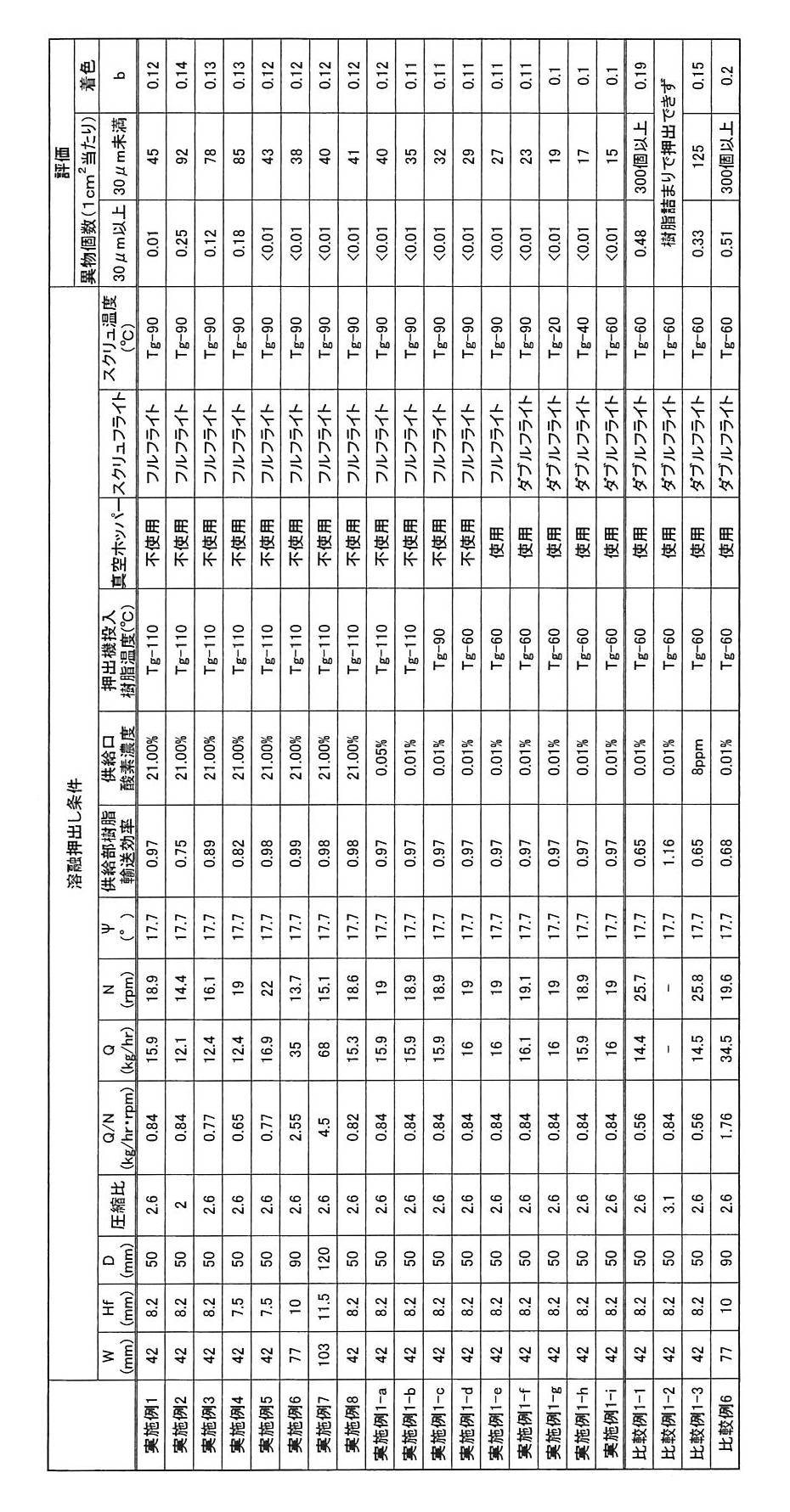
- Example 1 to Example 7 Cyclic olefin resin (ARTON (registered trademark) manufactured by JSR Corporation, specific gravity ⁇ : 1.08 (g / cm 3 ), glass transition temperature Tg: 138 ° C.) is used as a raw material resin, compression ratio, supply section groove depth Adjust Hf, the cylinder inner diameter D or Q / N of the extruder as shown in Table 1 (change the temperature of the extruder supply section A) so that each has a predetermined supply section resin transport efficiency. The melt extrusion was carried out.
- the screw of an extruder is a full flight type and a screw flight angle is 17.7 degrees.
- Example 8 Melt extrusion was carried out in the same manner as in Example 1 except that the raw material resin was changed to polycarbonate in Example 1.
- Example 1-a to Example 1-i> melt extrusion was performed in the same manner as in Example 1 except that the oxygen concentration at the supply port of the extruder, the charged resin temperature, the use of a vacuum hopper, the screw, or the screw temperature was changed.
- the screw flight angle in the double flight type supply unit in Examples 1-a to 1-i is 17.7 °.
- Example 1 except that in Example 1-i, Q / N was changed to 0.56 by changing the cylinder temperature of the extruder supply part (C1), and the supply part resin transport efficiency was adjusted to 0.65. Melt extrusion was carried out in the same manner as 1-i.
- Example 1-i melt extrusion was performed in the same manner as in Example 1-i, except that the compression ratio was 3.1 and the feeding part resin transport efficiency was adjusted to 1.16.
- Comparative Example 1-1 melt extrusion was performed in the same manner as in Comparative Example 1-1 except that the oxygen concentration was adjusted to 8 ppm by continuously supplying nitrogen gas to the supply port.
- Example 6 melt extrusion was carried out in the same manner as in Example 6 except that the Q / N was 1.76, the resin transport efficiency of the supply unit was 0.68, and the double flight type was used as the screw. .
- Table 1 shows the melt extrusion conditions and evaluation results of the films produced in each example.
Landscapes
- Engineering & Computer Science (AREA)
- Mechanical Engineering (AREA)
- Physics & Mathematics (AREA)
- Thermal Sciences (AREA)
- Manufacturing & Machinery (AREA)
- Extrusion Moulding Of Plastics Or The Like (AREA)
Abstract
Description
熱劣化異物の発生を抑制する対策として、例えば、特開2008-137328号公報では、溶融製膜する際に使用する押出機の開口部の酸素濃度を10ppm以下の不活性ガス雰囲気下にすることにより、樹脂の熱酸化劣化を抑制することが開示されている。
<1> 原料樹脂が供給される供給口及び原料樹脂が溶融した溶融樹脂が押出される押出口を有するシリンダーと、スクリュ軸及びスクリュ軸の周囲に螺旋状に配置されたフライトを有し、シリンダー内で回転するスクリュと、を備え、シリンダー内に、スクリュ軸に沿って供給口の側から順に、供給部、圧縮部及び計量部を有する押出機を用い、下記式で算出される供給部樹脂輸送効率が、0.75≦供給部樹脂輸送効率≦1.0を満たす条件で、原料樹脂の供給及び溶融を行い、押出口から押出された溶融樹脂をダイからフィルム状に溶融押出しする工程を有する熱可塑性樹脂フィルムの製造方法。

Hf:供給部における溝深さ(mm)
D:シリンダーの内径(mm)
Ψ:供給部におけるスクリュフライト角(°)
Q:溶融樹脂の押出量(kg/h)
ρ:原料樹脂の比重(g/cm3)
N:1分間当たりのスクリュ回転数(rpm)
圧縮比:供給部におけるスクリュフライト1ピッチあたりの容積/計量部におけるスクリュフライト1ピッチあたりの容積
<3> 原料樹脂のガラス転移温度をTg℃とした場合に、供給口からシリンダー内に供給する原料樹脂の温度が、Tg-90℃以上、Tg+10℃以下である<1>又は<2>に記載の熱可塑性樹脂フィルムの製造方法。
<4> 原料樹脂を、真空ホッパーを通じて供給口からシリンダー内に供給する<1>~<3>のいずれか1つに記載の熱可塑性樹脂フィルムの製造方法。
<5> スクリュがダブルフライトスクリュである<1>~<4>のいずれか1つに記載の熱可塑性樹脂フィルムの製造方法。
<6> 原料樹脂のガラス転移温度をTg℃とした場合に、供給部におけるスクリュの温度を、Tg-80℃以上、Tg℃以下に制御する<1>~<5>のいずれか1つに記載の熱可塑性樹脂フィルムの製造方法。
<7> 原料樹脂が環状オレフィン樹脂である<1>~<6>のいずれか1つに記載の熱可塑性樹脂フィルムの製造方法。
また、以下の説明において数値範囲を表す「~」はその前後に下限値及び上限値として記載されている数値を含む範囲を意味し、上限値又は下限値のみに単位が付されている場合は、その数値範囲全体において同じ単位であることを意味する。
本明細書において「工程」との語は、独立した工程だけでなく、他の工程と明確に区別できない場合であっても工程の所期の目的が達成されれば、本用語に含まれる。
本明細書において、「(共)重合体」とは、特定の繰り返し単位を含む単独重合体及び共重合体の双方又はいずれかを意味する。
本明細書中に段階的に記載されている数値範囲において、ある数値範囲で記載された上限値又は下限値は、他の段階的な記載の数値範囲の上限値又は下限値に置き換えてもよい。また、本明細書中に記載されている数値範囲において、ある数値範囲で記載された上限値又は下限値は、実施例に示されている値に置き換えてもよい。

W:供給部におけるスクリュフライト間隔(mm)
Hf:供給部における溝深さ(mm)
D:シリンダーの内径(mm)
Ψ:供給部におけるスクリュフライト角(°)
Q:溶融樹脂の押出量(kg/h)
ρ:原料樹脂の比重(g/cm3)
N:1分間当たりのスクリュ回転数(rpm)
圧縮比:供給部におけるスクリュフライト1ピッチあたりの容積/計量部におけるスクリュフライト1ピッチあたりの容積
また、熱可塑性樹脂を「樹脂」、熱可塑性樹脂フィルムを「フィルム」と記す場合がある。
図1は、本開示の熱可塑性樹脂フィルムの製造方法を実施するための製膜装置(熱可塑性樹脂フィルム製造装置)の全体構成の一例を概略的に示している。
図1に示す製膜装置10は、原料樹脂としての熱可塑性樹脂が投入されるホッパー12と、ホッパー12から供給された熱可塑性樹脂を溶融する押出機14と、溶融した樹脂(溶融樹脂)の押出量を安定化させるギアポンプ16と、溶融樹脂を濾過するフィルター18と、溶融樹脂をフィルム状に溶融押出するダイ20と、ダイ20から吐出された高温の熱可塑性樹脂を多段冷却する複数の冷却ロール(以下、冷却ロールをキャスティングロールと称することがある)22、24、26と、ダイ20から吐出された熱可塑性樹脂100を第1冷却ロール22との間で挟み込む接触ロール(以下、接触ロールをタッチロールと称することがある)28とを備えている。なお、図示されていないが、通常は、最後の第3冷却ロール26から熱可塑性樹脂フィルム100を剥離する剥離ロールと、冷却されたフィルムを巻き取る巻取機とが設けられる。
図2に示すように、押出機14は、シリンダー44と、シリンダー内に配置されたスクリュ50と、を備えている。
シリンダー44は、熱可塑性樹脂が供給される供給口52及び熱可塑性樹脂が溶融した溶融樹脂が押出される押出口54を有し、シリンダー44内は、スクリュ軸46に沿って、供給口52側から順に、供給口52から供給された熱可塑性樹脂を予熱しながら輸送する供給部(図2においてAで示す領域)と、熱可塑性樹脂を圧縮しながら混練して溶融する圧縮部(図2においてBで示す領域)と、溶融された樹脂を計量し、押出量を安定化する計量部(図2においてCで示す領域)と、を有する。図3は、押出機14の供給部Aを拡大して概略的に示す図である。
また、図2に示すシリンダー44の供給口52には、図1に示すホッパー12が取り付けられている。
ダイ20から溶融押出しされたフィルム状の熱可塑性樹脂は、接触ロール(タッチロール)28と第1冷却ロール22との間に挟み込まれ、第2冷却ロール24、第3冷却ロール26を経て、不図示の巻取機により巻き取られる。
本開示における供給部樹脂輸送効率の算出式において、最初の項の分数の分子「Q/N」は、溶融押出し工程におけるスクリュ1回転当たりの溶融樹脂の押出量を意味している。一方、分母は、シリンダー内の供給部における理論輸送量を意味し、理論輸送量を圧縮比で割ることで、圧縮比に関係無く高効率に輸送できればよいことを意味している。また、(D/90)0.5はシリンダー内径に対する補正係数である。
そのため、大掛かりな雰囲気置換をせずとも、得られたフィルムにおける樹脂と酸素との反応によって生じる熱劣化異物の発生が抑制された熱可塑性樹脂フィルムを製造することができると考えられる。
本開示で用いる原料樹脂は熱可塑性樹脂であれば特に限定されず、製造するフィルムの用途に応じて選択すればよい。
例えば、光学フィルムを製造する場合は、熱可塑性樹脂としては、得られるフィルムの透明性が良好であるという観点から、アクリル樹脂、メタクリル樹脂、ポリカーボネート(PC)樹脂、環状オレフィン樹脂を好適に用いることができる。なかでも、環状オレフィン樹脂が好ましい。
環状オレフィン樹脂は、環状オレフィン構造を有する(共)重合体樹脂であり、環状オレフィン構造を有する重合体樹脂の例としては、(1)ノルボルネン系重合体、(2)単環の環状オレフィンの重合体、(3)環状共役ジエンの重合体、(4)ビニル脂環式炭化水素重合体、及び(1)~(4)の水素化物などが挙げられる。
なお、本明細書におけるノルボルネン系重合体とは、ノルボルネン構造を有する繰り返し単位を含む単独重合体、及び共重合体を含む意味で用いられ、ノルボルネン構造は、開環であってもよい。
例えば、環状オレフィン構造を有する重合体樹脂としては、下記一般式(II)で表される繰り返し単位を少なくとも1種以上含む付加(共)重合体環状ポリオレフィン及び必要に応じ、一般式(I)で表される繰り返し単位の少なくとも1種以上を更に含んでなる付加共重合体環状ポリオレフィンが挙げられる。
また、環状オレフィン構造を有する重合体樹脂としては、一般式(III)で表される環状繰り返し単位を少なくとも1種含む開環(共)重合体も好適に使用することができる。

分極性の大きい官能基とは、電気陰性度の異なる2種以上の原子を含み、双極子モーメントを有する官能基を意味する。分極性の大きい官能基としては、具体的には例えば、カルボキシ基、カルボニル基、エポキシ基、エーテル基、ヒドロキシ基、アミノ基、イミノ基、シアノ基、アミド基、イミド基、エステル基、スルホン基等を挙げることができる。
ノルボルネン系付加(共)重合体は、市販品を用いてもよい。ノルボルネン系付加(共)重合体は、三井化学(株)よりアペル(登録商標)の商品名で市販されており、ガラス転移温度(Tg)の異なる、例えばAPL8008T(Tg:70℃)、APL6013T(Tg:125℃)、APL6015T(Tg:145℃)などのグレードがある。ポリプラスチック(株)よりTOPAS8007、同6013、同6015などのノルボルネン系付加(共)重合体がペレットとして市販されている。更に、Ferrania社よりノルボルネン系付加(共)重合体として、Appear3000が市販されている。
本開示の製造方法において用いるノルボルネン系重合体としては、上記一般式(III)で表される環状繰り返し単位を含む重合体が好ましく、一般式(III)で表される環状繰り返し単位において、R5及びR6は水素原子又は-CH3が好ましく、X3、及びY3は水素原子、-Cl又は-COOCH3が好ましく、その他の基は適宜選択される。
ノルボルネン系樹脂は、JSR(株)からアートン(Arton:登録商標)GあるいはアートンFという商品名で市販されており、日本ゼオン(株)からゼオノア(Zeonor:登録商標)ZF14、ZF16、ゼオネックス(Zeonex:登録商標)250またはゼオネックス280という商品名で市販されており、これらを使用することができる。
ペレット化を行うにあたり熱可塑性樹脂は事前に乾燥を行うことが好ましい。また、固体状添加剤を使用する場合、添加剤も事前に乾燥を行うことが好ましい。熱可塑性樹脂の乾燥を行う場合、乾燥方法、乾燥条件は特に限定されない。乾燥方法としては、例えば、加熱炉内にて80℃~110℃、好ましくは90℃前後の温度条件で、加熱時間8時間以上、好ましくは8時間~12時間加熱する方法等が例示されるが、この限りではない。熱可塑性樹脂を乾燥する際の加熱温度及び加熱時間は、熱可塑性樹脂のガラス転移温度Tg及び融点などの少なくともいずれかを考慮して選択すればよい。
添加剤が油状物等、流動性を有する場合には、そのまま、押出し機に投入し、押出し機中で熱可塑性樹脂と混合すればよい。
熱可塑性樹脂のペレット化を行う時に、必要に応じて添加される添加剤は、予め熱可塑性樹脂と混合せず、ペレット化に使用される押出機の途中にある原料投入口又はベント口から投入することもできる。
ペレットを乾燥する場合の乾燥温度は、好ましくは0℃~200℃であり、さらに好ましくは40℃~180℃であり、特に好ましくは60℃~150℃である。
原料樹脂をホッパー12に投入し、シリンダー44の供給口52からシリンダー44内に供給する。ホッパー12に投入する原料樹脂は、熱可塑性樹脂のペレットであってもよく、熱可塑性樹脂と添加剤とを含むペレットであってもよく、フレーク状の熱可塑性樹脂であってもよい。
シリンダー44に供給する熱可塑性樹脂の熱酸化を抑制する観点から、供給口52における酸素濃度は低いことが好ましく、具体的には体積基準で0.1%以下であることが好ましい。供給口52における酸素濃度を低くする方法としては、原料樹脂を、真空ホッパーを通じて供給口52からシリンダー44内に供給する方法、シリンダー44の供給口52に窒素ガスを供給する方法などが挙げられる。なお、供給口52における酸素濃度は、供給口52に配管(図示せず)を設けて酸素濃度計(図示せず)を接続することによって測定することができる。
熱可塑性樹脂のガラス転移温度をTg(℃)とした場合に、供給口52からシリンダー44内に供給する熱可塑性樹脂の温度が、Tg-90℃以上、Tg+10℃以下であることが好ましく、Tg-80℃以上、Tg-10℃以下に制御することがより好ましい。供給口52からシリンダー44内に供給する熱可塑性樹脂の温度を上記の好ましい範囲に制御する方法としては、ホッパーに投入するペレットを予め加熱しておく方法、加熱手段を備えたホッパーを用いる方法、ホッパーとは別に供給口付近に加熱手段を設ける方法などが挙げられる。
供給口52からシリンダー44内に供給された熱可塑性樹脂は、スクリュ50の回転により、供給部Aにおいて予熱されながら押出口54に向けて輸送される。
本開示における供給部樹脂輸送効率の算出式において、Wは、シリンダー内の供給部におけるスクリュ50のフライト間隔(mm)を示している。スクリュフライト間隔Wは、供給部樹脂輸送効率を0.75以上1.0以下にして溶融押出しを実施する観点から、10mm~300mmが好ましく、20mm~250mmがより好ましい。
本開示における供給部樹脂輸送効率の算出式において、Nは、スクリュ回転数(rpm:回転/分)を示している。本開示の熱可塑性樹脂フィルムの製造方法では、供給部において熱可塑性樹脂が密な状態でスクリュを回転させることになるため、通常は、高いトルクであり、かつ、比較的低速でスクリュを回転させることになる。かかる観点から、本開示の製造方法におけるスクリュ回転数(rpm)は、3rpm~150rpmが好ましく、5rpm~100rpmがより好ましい。
一般的に、シリンダー44が高温であれば、シリンダー44に対する樹脂の摩擦力が高くなり、スクリュ50が低温であれば、スクリュ50に対する樹脂の摩擦力が低くなり、摩擦力差が生じて樹脂を圧縮部B側に送り易くなるという関係となる。熱可塑性樹脂のガラス転移温度をTg(℃)とした場合に、スクリュ50の温度をTgよりも高温にして供給部Aで原料樹脂を軟化させる温度に設定すると、スクリュ50に対する樹脂の摩擦力とシリンダー44に対する樹脂の摩擦力の差が小さくなり、樹脂を溶融させる圧縮部Bに進み難くなる可能性がある。かかる観点から、供給部Aにおけるスクリュの温度をTg-80℃以上Tg℃以下に制御することが好ましく、Tg-70℃以上Tg-10℃以下に制御することがより好ましい。例えば、スクリュ軸の内部に熱媒体を循環供給する構造を有するスクリュを用いることでスクリュの温度を高精度に制御することができる。
本開示における供給部樹脂輸送効率の算出式において、圧縮比は、「供給部におけるスクリュフライト1ピッチあたりの容積/計量部におけるスクリュフライト1ピッチあたりの容積」を示している。圧縮比は、供給部Aのスクリュ軸の外径d1、計量部Cのスクリュ軸の外径d2、供給部Aの溝深さHf、及び計量部Cの溝深さHmを使用して算出される。
圧縮比は、上記観点及び供給部樹脂輸送効率を0.75以上1.0以下にして溶融押出しを実施する観点から、1.5~4.0が好ましく、2.0~3.5がより好ましい。なお、圧縮比は、シリンダー44の内径D、供給部及び計量部におけるスクリュ軸の外径d1、d2、スクリュ50のフライト間隔W、及びフライト角Ψの少なくともいずれかを調整することによって調整することができる。
押出温度は200℃~300℃に設定されることが好ましい。
押出機内の設定温度は、全領域が同じ温度でもよく、領域により異なる温度分布としてもよい。領域により異なる温度分布とすることが好ましく、なかでも、押出機において既述の供給部Aの温度を圧縮部Bの温度より高くすることがより好ましい。
かかる観点から、L/Dは20~70の範囲が好ましく、より好ましくは22~60の範囲であり、さらに好ましくは24~50の範囲である。
フィルムの厚み精度を向上させるために、押出機14から押出される溶融樹脂の吐出量の変動を低く抑えることが重要である。吐出量の変動をより低減させるという観点からは、押出機14とダイ20との間にギアポンプ16を設けて、ギアポンプ16から一定量の溶融樹脂を供給することが好ましい。
ギアポンプは、ドライブギアとドリブンギアとからなる一対のギアが互いに噛み合った状態で収容され、ドライブギアを駆動して両ギアを噛み合い回転させることにより、ハウジングに形成されている吸引口から溶融状態の樹脂をキャビティ内に吸引し、同じくハウジングに形成されている吐出口から樹脂を一定量吐出する。押出機の先端部分の樹脂圧力が若干の変動があっても、ギアポンプを用いることにより、変動を吸収し、製膜装置下流の樹脂圧力の変動は非常に小さくなり、厚み変動が改善される。ギアポンプを用いることにより、ダイ部分の樹脂圧力の変動幅を±1%以内にすることが可能である。
より高い精度で異物の混入を防ぐために、ギアポンプ16通過後にフィルター18を設けることが好ましい。フィルター18としては、いわゆるリーフ型ディスクフィルターを組み込んだ濾過装置が好ましい。押出機から吐出される熱可塑性樹脂の濾過は、濾過部を1カ所設けて行う濾過であってもよく、また、濾過部を複数カ所設けて行う多段濾過でもよい。フィルター濾材の濾過精度は高い方が好ましい。しかし、濾材の耐圧を考慮したり、濾材の目詰まりによる濾圧上昇を抑制したりするという観点から、濾過精度は15μm~3μmが好ましく、10μm~3μmがより好ましい。特に最終的に異物濾過を行うリーフ型ディスクフィルター装置を使用する場合には、品質の上で濾過精度の高い濾材を使用することが好ましく、耐圧、フィルター寿命の適性を確保するために、濾過部に装填する濾材の枚数にて耐圧、フィルターの寿命等を調整することが可能である。
濾材の構成としては、線材を編んで形成された濾材の他に、例えば金属長繊維あるいは金属粉末を焼結して形成する焼結濾材が使用でき、濾過精度、フィルター寿命の点から焼結濾材が好ましい。
押出機14、ギアポンプ16及びフィルター18を経てダイ20に連続的に送られた溶融樹脂(メルト)は、ダイ20からフィルム状に溶融押出しされる。
ダイ20の直前に樹脂温度の均一性向上のためのスタティックミキサーを入れてもよい。
ダイ20のスリット間隔(リップクリアランス)は、一般的に、フィルム厚みの1.0~5.0倍が好ましく、より好ましくは1.2~3倍、さらに好ましくは1.3~2倍である。リップクリアランスがフィルム厚みの1.0倍以上であれば、製膜により面状の良好なフィルムが得られ易い。また、リップクリアランスがフィルム厚みの5.0倍以下であればフィルムの厚み精度を向上させることができる。
また、フィルムの均一性をより向上するために、ダイの温度ムラや幅方向の流速ムラをできるだけ少なくし得る諸条件に調整することが好ましい。また、下流のフィルムの厚みを計測して、厚み偏差を計算し、その結果をダイの厚み調整にフィードバックさせる自動厚み調整ダイを用いることも長期連続生産の厚み変動の低減に有効である。
上記条件にて、ダイよりフィルム状に押し出された溶融樹脂をキャスティングロール上において冷却固化し、熱可塑性樹脂フィルムを得る。なお、溶融樹脂がキャスティングロールに接触する前に、溶融押出されたフィルムを遠赤外線ヒーターで加熱することにより、ドラム上でレベリング効果が発現して、溶融押出されたフィルムの表面がより均一となり、得られるフィルムの膜厚分布を小さくし、ダイスジの発生を抑制することができる。
吐出された熱可塑性樹脂の冷却に複数のキャスティングロールを用いる場合、タッチロールは最上流側(ダイに近い方)の最初のキャスティングロールにタッチさせる位置に配置することが好ましい。
キャスティングロールを複数用いる場合、隣接するキャスティングロールの間隔は、面間で0.3mm~300mmが好ましく、より好ましくは、1mm~100mm、さらに好ましくは3mm~30mmである。
また、キャスティングロールの最上流側のライン速度は20m/分以上70m/分以下とするのが好ましい。
冷却されたフィルム(未延伸フィルム)をキャスティングロールから剥ぎ取った後、ニップロール(不図示)を経て巻き取る。
製膜したフィルムは、目的に応じて延伸を行うことができる。
延伸を行う場合、製膜したフィルムは、そのまま延伸するオンライン延伸を施してもよく、一旦巻き取った後、再度送り出して延伸するオフライン延伸を施してもよい。
さらに、延伸と組み合わせて、後述の緩和処理をおこなってもよい。これらは例えば以下の組合せで実施できる。
得られた樹脂フィルムの延伸後に緩和処理を行うことで樹脂フィルムの寸法安定性を改良できる。緩和処理は延伸フィルムの縦方向及び横方向の少なくともいずれかの寸法を、例えば、1%~8%程度緩和した状態で、熱固定する熱緩和処理が好ましい。熱緩和処理における温度は、熱可塑性樹脂フィルムに用いられる熱可塑性樹脂の種類により適宜選択されるが、一般的には、130℃~240℃が好ましい。
熱緩和は、縦延伸後、横延伸後のいずれか、あるいは両方で行うことが好ましく、より好ましくは横延伸後である。緩和処理は熱可塑性樹脂フィルムの延伸後に連続してオンラインで行ってもよく、延伸後、巻き取った熱可塑性樹脂フィルムに対し、オフラインで行ってもよい。
本開示の製造方法により製造される環状オレフィン樹脂フィルムは、熱劣化異物の発生が抑制され、光学特性が良好であるため、フィルム単独で光学フィルムとして使用してもよい。また、偏光板と組み合わせて使用してもよく、液晶層、屈折率を制御した層(低反射層)、ハードコート層等の機能層を設けて使用してもよく、得られた環状オレフィン樹脂フィルムの応用範囲は広い。
原料の樹脂ペレットを、100℃で5時間予備乾燥した。
予備乾燥後、押出機に設けたホッパーに樹脂ペレットを投入し、押出機により270℃で溶融した。なお、上記温度は、圧縮部以降のシリンダーの温度である。
押出機から押出され、配管を通じてギアポンプに輸送された溶融樹脂(メルト)は、さらにギアポンプから送り出され、濾過精度5μmのリーフ型ディスクフィルターにて濾過された。
原料樹脂として、環状オレフィン樹脂(JSR株式会社製 ARTON(登録商標)、比重ρ:1.08(g/cm3)、ガラス転移温度Tg:138℃)を用い、圧縮比、供給部溝深さHf、押出機のシリンダー内径D、又はQ/Nを表1に示すように変化(押出機供給部Aの温度を変化)させることで、それぞれ所定の供給部樹脂輸送効率を持つように調整して溶融押出しを実施した。なお、押出機のスクリュは、フルフライトタイプであり、スクリュフライト角は17.7°である。
実施例1において原料樹脂をポリカーボネートに変更したこと以外は実施例1と同様にして溶融押出しを実施した。
実施例1において、押出機の供給口における酸素濃度、投入樹脂温度、真空ホッパーの使用、スクリュ、又はスクリュ温度を変更したこと以外は実施例1と同様にして溶融押出しを実施した。なお、実施例1-a~実施例1-iにおけるダブルフライトタイプの供給部におけるスクリュフライト角は、17.7°である。
実施例1-iにおいて、押出機供給部(C1)のシリンダー温度を変化させることでQ/Nを0.56に変化させて供給部樹脂輸送効率を0.65に調整したこと以外は実施例1-iと同様にして溶融押出しを実施した。
実施例1-iにおいて、圧縮比を3.1にして供給部樹脂輸送効率を1.16に調整したこと以外は実施例1-iと同様にして溶融押出しを実施した。
比較例1-1において、供給口に窒素ガスを連続的に供給することにより酸素濃度を8ppmにしたこと以外は比較例1-1と同様にして溶融押出しを実施した。
実施例6において、Q/Nを1.76にして供給部樹脂輸送効率を0.68にしたこと、及びスクリュとしてダブルフライトタイプを用いた以外は実施例6と同様にして溶融押出しを実施した。
<異物数の評価>
各例で製造した樹脂フィルム(厚み:100μm)中の異物数について、ニコン社製の微分干渉顕微鏡(200倍)を用い、フィルムのセンター部分を10cm×10cmの範囲で測定を行った。測定では、最大長が30μm以上の異物数と5μm以上30μm未満の異物数をそれぞれ記録した。
各例で製造した樹脂フィルム(厚み:100μm)について、色差計(スガ試験機株式会社製、SM-T)を用いてLabを測定し、b値で黄色度を評価した。b値の数値が小さいほど、黄色度が低く、樹脂フィルムの着色が抑制されていると評価する。
本明細書に記載された全ての文献、特許出願、及び技術規格は、個々の文献、特許出願、及び技術規格が参照により取り込まれることが具体的かつ個々に記された場合と同程度に、本明細書中に参照により取り込まれる。
Claims (8)
- 原料樹脂が供給される供給口及び前記原料樹脂が溶融した溶融樹脂が押出される押出口を有するシリンダーと、スクリュ軸及びスクリュ軸の周囲に螺旋状に配置されたフライトを有し、前記シリンダー内で回転するスクリュと、を備え、前記シリンダー内に、前記スクリュ軸に沿って前記供給口の側から、供給部、圧縮部及び計量部を順に有する押出機を用い、下記式で算出される供給部樹脂輸送効率が、0.75≦供給部樹脂輸送効率≦1.0を満たす条件で、前記原料樹脂の供給及び溶融を行い、前記押出口から押出された前記溶融樹脂をダイからフィルム状に溶融押出しする工程を有する熱可塑性樹脂フィルムの製造方法。

W:供給部におけるスクリュフライト間隔(mm)
Hf:供給部における溝深さ(mm)
D:シリンダーの内径(mm)
Ψ:供給部におけるスクリュフライト角(°)
Q:溶融樹脂の押出量(kg/h)
ρ:原料樹脂の比重(g/cm3)
N:1分間当たりのスクリュ回転数(rpm)
圧縮比:供給部におけるスクリュフライト1ピッチあたりの容積/計量部におけるスクリュフライト1ピッチあたりの容積 - 前記供給口における酸素濃度が0.1%以下である請求項1に記載の熱可塑性樹脂フィルムの製造方法。
- 前記原料樹脂のガラス転移温度をTg℃とした場合に、前記供給口から前記シリンダー内に供給する前記原料樹脂の温度が、Tg-90℃以上、Tg+10℃以下である請求項1又は請求項2に記載の熱可塑性樹脂フィルムの製造方法。
- 前記原料樹脂を、真空ホッパーを通じて前記供給口から前記シリンダー内に供給する請求項1~請求項3のいずれか1項に記載の熱可塑性樹脂フィルムの製造方法。
- 前記スクリュがダブルフライトスクリュである請求項1~請求項4のいずれか1項に記載の熱可塑性樹脂フィルムの製造方法。
- 前記原料樹脂のガラス転移温度をTg℃とした場合に、前記供給部における前記スクリュの温度を、Tg-80℃以上、Tg℃以下に制御する請求項1~請求項5のいずれか1項に記載の熱可塑性樹脂フィルムの製造方法。
- 前記原料樹脂が環状オレフィン樹脂である請求項1~請求項6のいずれか1項に記載の熱可塑性樹脂フィルムの製造方法。
- 厚さ100μm当たり、最長径が30μm以上の異物数が0.3個/cm2以下であり、かつ、最長径が5μm以上30μm未満の異物数が100個/cm2以下である環状オレフィン樹脂フィルム。
Priority Applications (3)
| Application Number | Priority Date | Filing Date | Title |
|---|---|---|---|
| JP2017562864A JP6545289B2 (ja) | 2016-01-22 | 2017-01-18 | 熱可塑性樹脂フィルムの製造方法及び環状オレフィン樹脂フィルム |
| CN201780006893.2A CN108472849B (zh) | 2016-01-22 | 2017-01-18 | 热塑性树脂薄膜的制造方法及环状烯烃树脂薄膜 |
| KR1020187020315A KR102013606B1 (ko) | 2016-01-22 | 2017-01-18 | 열가소성 수지 필름의 제조 방법 및 환상 올레핀 수지 필름 |
Applications Claiming Priority (2)
| Application Number | Priority Date | Filing Date | Title |
|---|---|---|---|
| JP2016-011074 | 2016-01-22 | ||
| JP2016011074 | 2016-01-22 |
Publications (1)
| Publication Number | Publication Date |
|---|---|
| WO2017126572A1 true WO2017126572A1 (ja) | 2017-07-27 |
Family
ID=59362444
Family Applications (1)
| Application Number | Title | Priority Date | Filing Date |
|---|---|---|---|
| PCT/JP2017/001613 Ceased WO2017126572A1 (ja) | 2016-01-22 | 2017-01-18 | 熱可塑性樹脂フィルムの製造方法及び環状オレフィン樹脂フィルム |
Country Status (5)
| Country | Link |
|---|---|
| JP (1) | JP6545289B2 (ja) |
| KR (1) | KR102013606B1 (ja) |
| CN (1) | CN108472849B (ja) |
| TW (1) | TW201736084A (ja) |
| WO (1) | WO2017126572A1 (ja) |
Cited By (5)
| Publication number | Priority date | Publication date | Assignee | Title |
|---|---|---|---|---|
| CN110014613A (zh) * | 2018-08-01 | 2019-07-16 | 东莞天天向上医疗科技有限公司 | 一种单螺杆精密挤出机螺杆 |
| WO2019163637A1 (ja) * | 2018-02-21 | 2019-08-29 | 富士フイルム株式会社 | 環状オレフィン樹脂フィルムの製造方法、環状オレフィン樹脂フィルム、複合フィルム |
| WO2020039887A1 (ja) * | 2018-08-23 | 2020-02-27 | 株式会社神戸製鋼所 | 押出機 |
| WO2020066350A1 (ja) * | 2018-09-28 | 2020-04-02 | 富士フイルム株式会社 | ポリマーフィルム、及び表示装置 |
| CN116218417A (zh) * | 2022-12-29 | 2023-06-06 | 大连大诺印刷包装有限公司 | 一种用于金属保护膜的粘接树脂的生产工艺 |
Families Citing this family (3)
| Publication number | Priority date | Publication date | Assignee | Title |
|---|---|---|---|---|
| FR3056435B1 (fr) | 2016-09-26 | 2019-05-31 | Armor | Methode de production d'un materiau densifie a partir d'un film complexe, installation de production et utilisation. |
| CN114083793B (zh) * | 2021-10-18 | 2024-05-17 | 深圳市创想三维科技股份有限公司 | 挤出机构及3d打印机 |
| CN117482773B (zh) * | 2023-11-03 | 2024-07-02 | 山东凯恩新材料科技有限公司 | 一种热熔胶的制备方法 |
Citations (4)
| Publication number | Priority date | Publication date | Assignee | Title |
|---|---|---|---|---|
| JP2005015598A (ja) * | 2003-06-25 | 2005-01-20 | Jsr Corp | 環状オレフィン系樹脂フィルムまたはシートの製造方法 |
| JP2007253364A (ja) * | 2006-03-20 | 2007-10-04 | Fujifilm Corp | 熱可塑性樹脂フィルム及びその製造方法 |
| JP2009083322A (ja) * | 2007-09-28 | 2009-04-23 | Fujifilm Corp | 環状オレフィン系樹脂フィルム及びその製造方法 |
| JP2013119201A (ja) * | 2011-12-07 | 2013-06-17 | Konica Minolta Advanced Layers Inc | 熱可塑性樹脂フィルムの製造方法 |
Family Cites Families (1)
| Publication number | Priority date | Publication date | Assignee | Title |
|---|---|---|---|---|
| US20090312535A1 (en) * | 2005-09-14 | 2009-12-17 | Fujifilm Corporation | Cellulose resin film and method for producing the same |
-
2017
- 2017-01-18 JP JP2017562864A patent/JP6545289B2/ja active Active
- 2017-01-18 CN CN201780006893.2A patent/CN108472849B/zh active Active
- 2017-01-18 WO PCT/JP2017/001613 patent/WO2017126572A1/ja not_active Ceased
- 2017-01-18 KR KR1020187020315A patent/KR102013606B1/ko active Active
- 2017-01-20 TW TW106101986A patent/TW201736084A/zh unknown
Patent Citations (4)
| Publication number | Priority date | Publication date | Assignee | Title |
|---|---|---|---|---|
| JP2005015598A (ja) * | 2003-06-25 | 2005-01-20 | Jsr Corp | 環状オレフィン系樹脂フィルムまたはシートの製造方法 |
| JP2007253364A (ja) * | 2006-03-20 | 2007-10-04 | Fujifilm Corp | 熱可塑性樹脂フィルム及びその製造方法 |
| JP2009083322A (ja) * | 2007-09-28 | 2009-04-23 | Fujifilm Corp | 環状オレフィン系樹脂フィルム及びその製造方法 |
| JP2013119201A (ja) * | 2011-12-07 | 2013-06-17 | Konica Minolta Advanced Layers Inc | 熱可塑性樹脂フィルムの製造方法 |
Cited By (12)
| Publication number | Priority date | Publication date | Assignee | Title |
|---|---|---|---|---|
| WO2019163637A1 (ja) * | 2018-02-21 | 2019-08-29 | 富士フイルム株式会社 | 環状オレフィン樹脂フィルムの製造方法、環状オレフィン樹脂フィルム、複合フィルム |
| KR20200108463A (ko) * | 2018-02-21 | 2020-09-18 | 후지필름 가부시키가이샤 | 환상 올레핀 수지 필름의 제조 방법, 환상 올레핀 수지 필름, 복합 필름 |
| CN111727111A (zh) * | 2018-02-21 | 2020-09-29 | 富士胶片株式会社 | 环状烯烃树脂膜的制造方法、环状烯烃树脂膜、复合膜 |
| JPWO2019163637A1 (ja) * | 2018-02-21 | 2020-12-03 | 富士フイルム株式会社 | 環状オレフィン樹脂フィルムの製造方法、環状オレフィン樹脂フィルム、複合フィルム |
| KR102361868B1 (ko) * | 2018-02-21 | 2022-02-14 | 후지필름 가부시키가이샤 | 환상 올레핀 수지 필름의 제조 방법, 환상 올레핀 수지 필름, 복합 필름 |
| CN111727111B (zh) * | 2018-02-21 | 2022-08-23 | 富士胶片株式会社 | 环状烯烃树脂膜的制造方法、环状烯烃树脂膜、复合膜 |
| CN110014613A (zh) * | 2018-08-01 | 2019-07-16 | 东莞天天向上医疗科技有限公司 | 一种单螺杆精密挤出机螺杆 |
| WO2020039887A1 (ja) * | 2018-08-23 | 2020-02-27 | 株式会社神戸製鋼所 | 押出機 |
| WO2020066350A1 (ja) * | 2018-09-28 | 2020-04-02 | 富士フイルム株式会社 | ポリマーフィルム、及び表示装置 |
| JPWO2020066350A1 (ja) * | 2018-09-28 | 2021-04-30 | 富士フイルム株式会社 | ポリマーフィルム、及び表示装置 |
| JP7016425B2 (ja) | 2018-09-28 | 2022-02-04 | 富士フイルム株式会社 | ポリマーフィルム、及び表示装置 |
| CN116218417A (zh) * | 2022-12-29 | 2023-06-06 | 大连大诺印刷包装有限公司 | 一种用于金属保护膜的粘接树脂的生产工艺 |
Also Published As
| Publication number | Publication date |
|---|---|
| JP6545289B2 (ja) | 2019-07-17 |
| TW201736084A (zh) | 2017-10-16 |
| JPWO2017126572A1 (ja) | 2018-11-08 |
| CN108472849A (zh) | 2018-08-31 |
| KR20180095016A (ko) | 2018-08-24 |
| CN108472849B (zh) | 2020-08-25 |
| KR102013606B1 (ko) | 2019-08-23 |
Similar Documents
| Publication | Publication Date | Title |
|---|---|---|
| JP6545289B2 (ja) | 熱可塑性樹脂フィルムの製造方法及び環状オレフィン樹脂フィルム | |
| JP7443553B2 (ja) | 液晶ポリマーフィルム、フレキシブル銅張積層板及び液晶ポリマーフィルムの製造方法 | |
| CN101664991B (zh) | 用于制备膜的方法和光学膜 | |
| CN101516604A (zh) | 制备纤维素树脂膜的方法及装置和光学纤维素树脂膜 | |
| CN101272895B (zh) | 热塑性树脂膜及其制备方法 | |
| US20230331983A1 (en) | Liquid crystal polymer film and substrate for high-speed communication | |
| CN101516607B (zh) | 纵向拉伸热塑性树脂膜的方法以及由其制备的纵向拉伸膜 | |
| CN101180173B (zh) | 用于制备热塑性膜的方法 | |
| JP6910530B2 (ja) | 環状オレフィン樹脂フィルムの製造方法、環状オレフィン樹脂フィルム、複合フィルム | |
| CN101258015B (zh) | 纤维素树脂膜及其制备方法 | |
| JP6671495B2 (ja) | 熱可塑性樹脂フィルムの製造方法 | |
| JP7016425B2 (ja) | ポリマーフィルム、及び表示装置 | |
| JP7163846B2 (ja) | 光学フィルムの製造方法 | |
| US12522703B2 (en) | Polymer film and substrate for communication | |
| CN101262995A (zh) | 纤维素树脂膜及其制备方法 |
Legal Events
| Date | Code | Title | Description |
|---|---|---|---|
| 121 | Ep: the epo has been informed by wipo that ep was designated in this application |
Ref document number: 17741449 Country of ref document: EP Kind code of ref document: A1 |
|
| WWE | Wipo information: entry into national phase |
Ref document number: 2017562864 Country of ref document: JP |
|
| ENP | Entry into the national phase |
Ref document number: 20187020315 Country of ref document: KR Kind code of ref document: A |
|
| WWE | Wipo information: entry into national phase |
Ref document number: 1020187020315 Country of ref document: KR |
|
| NENP | Non-entry into the national phase |
Ref country code: DE |
|
| 122 | Ep: pct application non-entry in european phase |
Ref document number: 17741449 Country of ref document: EP Kind code of ref document: A1 |