WO2017122283A1 - 印刷装置および印刷方法 - Google Patents
印刷装置および印刷方法 Download PDFInfo
- Publication number
- WO2017122283A1 WO2017122283A1 PCT/JP2016/050744 JP2016050744W WO2017122283A1 WO 2017122283 A1 WO2017122283 A1 WO 2017122283A1 JP 2016050744 W JP2016050744 W JP 2016050744W WO 2017122283 A1 WO2017122283 A1 WO 2017122283A1
- Authority
- WO
- WIPO (PCT)
- Prior art keywords
- squeegee
- solder
- viscous material
- printing
- mask
- Prior art date
- Legal status (The legal status is an assumption and is not a legal conclusion. Google has not performed a legal analysis and makes no representation as to the accuracy of the status listed.)
- Ceased
Links
Images




Classifications
-
- B—PERFORMING OPERATIONS; TRANSPORTING
- B41—PRINTING; LINING MACHINES; TYPEWRITERS; STAMPS
- B41F—PRINTING MACHINES OR PRESSES
- B41F15/00—Screen printers
- B41F15/14—Details
- B41F15/40—Inking units
- B41F15/42—Inking units comprising squeegees or doctors
- B41F15/423—Driving means for reciprocating squeegees
-
- B—PERFORMING OPERATIONS; TRANSPORTING
- B41—PRINTING; LINING MACHINES; TYPEWRITERS; STAMPS
- B41F—PRINTING MACHINES OR PRESSES
- B41F15/00—Screen printers
- B41F15/08—Machines
- B41F15/0881—Machines for printing on polyhedral articles
-
- B—PERFORMING OPERATIONS; TRANSPORTING
- B41—PRINTING; LINING MACHINES; TYPEWRITERS; STAMPS
- B41F—PRINTING MACHINES OR PRESSES
- B41F15/00—Screen printers
- B41F15/14—Details
- B41F15/16—Printing tables
- B41F15/18—Supports for workpieces
- B41F15/26—Supports for workpieces for articles with flat surfaces
-
- B—PERFORMING OPERATIONS; TRANSPORTING
- B41—PRINTING; LINING MACHINES; TYPEWRITERS; STAMPS
- B41M—PRINTING, DUPLICATING, MARKING, OR COPYING PROCESSES; COLOUR PRINTING
- B41M1/00—Inking and printing with a printer's forme
- B41M1/12—Stencil printing; Silk-screen printing
Definitions
- a printing apparatus for printing a viscous material on a mask on a substrate is known.
- Such a printing apparatus is disclosed in, for example, Japanese Patent No. 5150092.
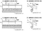
- 3 (D) is a side view showing the state of the solder when the separation speed is relatively slow. It is a figure for demonstrating the relationship between the viscosity of a solder, the thixotropy index
- the substrate holding unit 2 includes a backup unit 21, a clamp mechanism unit 22, and a drive mechanism unit 23.
- the backup unit 21 is configured to support the substrate P from below.
- the backup unit 21 includes a backup plate 21a, a plurality of backup pins 21b, and an elevating mechanism portion 21c.
- the backup plate 21a is configured to move in the vertical direction by the driving force of the elevating mechanism 21c.
- the plurality of backup pins 21b are provided on the backup plate 21a.
- the backup unit 21 is configured to lift the substrate P from the pair of conveyor portions 11 by a plurality of backup pins 21b and to support the substrate from below by moving the backup plate 21a upward.
- the drive mechanism unit 23 is a drive mechanism unit for aligning the substrate P and the mask M held by the pair of clamp mechanism units 22 and for bringing the substrate P and the mask M into contact with each other.
- the drive mechanism unit 23 includes a base plate 231, a Y-axis drive mechanism unit 232, an X-axis drive mechanism unit 233, an R-axis drive mechanism unit 234, and a Z-axis drive mechanism unit 235.
- a Y-axis drive mechanism 232 is provided under the base plate 231.
- a ball nut 231 a that is engaged (screwed) with a ball screw shaft 232 b (described later) of the Y-axis drive mechanism 232 is provided.
- the Z axis drive mechanism 235 is provided on the R axis drive mechanism 234. Further, the Z-axis drive mechanism unit 235 is configured to move the substrate P held by the pair of clamp mechanism units 22 in the vertical direction (Z direction).
- the Z-axis drive mechanism 235 includes a support plate 235a, a plurality of ball screw shafts 235b, and a plurality of ball nuts 235c.
- the squeegee 31 has a rectangular shape and is provided with a plate-like portion 31a for moving the solder Sp in contact with the solder Sp.
- the plate-like portion 31a of the squeegee 31 is formed so as to extend along the direction orthogonal to the printing direction so that the direction orthogonal to the printing direction (X direction) is the longitudinal direction.
- the mask M is a metal mask having a rectangular flat plate shape in plan view.
- the mask M is provided with a plurality of openings Ap constituting a print pattern.
- the solder Sp on the mask M contacts the plate-like portion 31a of the squeegee 31 and moves in the printing direction on the mask M, thereby filling the opening Ap of the mask M.
- the solder Sp is printed on the substrate P disposed below the mask M with the print pattern of the mask M.
- the mask M is disposed between the substrate holding unit 2 and the squeegee unit 3 while being attached to the frame 90.
- the frame 90 is held by a mask holding unit (not shown).
- the mounting portion 323 is configured to be movable in the Y direction along the ball screw shaft 322 together with a ball nut 323a engaged (screwed) with the ball screw shaft 322 by rotating the ball screw shaft 322 by the drive motor 321. Yes.
- the squeegee Y-axis drive mechanism 32 moves the squeegee 31, the squeegee Z-axis drive mechanism 33, the squeegee R-axis drive mechanism 34, and the solder supply unit 35 together with the attachment 323 in the printing direction (Y direction). It is configured as follows.
- a squeegee 31 is rotatably attached to the squeegee R-axis drive mechanism 34 via a support shaft 31b (see FIG. 3).
- the squeegee R-axis drive mechanism 34 extends in the X direction and is configured to rotate the squeegee 31 about an axis passing through the center of the support shaft 31b of the squeegee 31.
- the solder supply unit 35 is attached to the Y1 side of the squeegee Z-axis mechanism 33.
- the solder supply part 35 has a solder storage part 35a in which the solder Sp is stored, and is configured to be able to supply the solder Sp stored in the solder storage part 35a onto the mask M.
- the substrate recognition camera 4 is configured to be movable above the substrate holding unit 2.
- the board recognition camera 4 is configured to image a mark (not shown) attached to the board P from above the board P prior to the printing of the solder Sp on the board P.
- the imaging result of the substrate P by the substrate recognition camera 4 is acquired by the control unit 6.
- the controller 6 is configured to recognize the position of the substrate P based on the acquired imaging result of the substrate P.
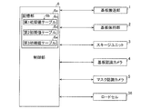
- the control unit 6 includes a CPU (Central Processing Unit) and is configured to control the operation of the printing apparatus 100.
- the control unit 6 is provided with a storage unit 6a.
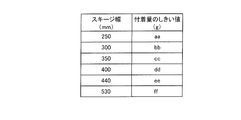
- An initial value table 6b is stored in the storage unit 6a. As shown in FIG. 5, the initial value table 6 b is a table for determining an initial value of the separation speed of the squeegee 31 based on the physical property value information of the solder Sp.
- control unit 6 controls the substrate transport unit 1, the substrate holding unit 2, the squeegee unit 3, the substrate recognition camera 4, the mask recognition camera 5, and the like according to the production program stored in advance, It is configured to perform printing of the solder Sp.
- the control unit 6 When printing the solder Sp on the substrate P, the control unit 6 brings the upper surface of the mask P and the plate-like portion 31a of the squeegee 31 into contact with the upper surface of the substrate P and the lower surface of the mask M in contact with each other. . Then, the control unit 6 moves the squeegee 31 in the printing direction (Y direction) on the mask M in a state where the mask M and the plate-like portion 31a of the squeegee 31 are in contact with each other, thereby moving the mask from the solder supply unit 35a. A printing operation for printing the solder Sp supplied on M on the substrate P is performed. During the printing operation, the solder Sp is moved on the mask M while being rolled by the squeegee 31. As a result, the solder Sp forms a solder roll (see FIG. 3) having a substantially bar shape on the mask M.
- the squeegee 31 is moved in the printing direction (Y1 direction) from the Y2 side of the mask M toward the Y1 side, and the squeegee 31 is separated from the solder Sp and the mask M on the Y1 side of the mask M. Later, the contact surface of the plate-like portion 31a of the squeegee 31 with the solder Sp is reversed from the Y1 side direction to the Y2 side direction.
- control part 6 is comprised so that the printing operation of the solder Sp to the next board
- control unit 6 is configured to acquire the initial value of the separation speed from the initial value table 6b so that the value increases as the viscosity of the solder Sp increases.
- control unit 6 is configured to obtain an initial value of the separation speed from the initial value table 6b so that the value increases as the thixo index of the solder Sp increases.
- the printing apparatus 100 is configured to perform test printing in order to determine the separation speed.
- test printing the printing operation of the solder Sp by the squeegee 31 on one substrate P and the separation operation of the squeegee 31 from the solder Sp after the printing operation are performed.
- the control unit 6 adheres the adhesion amount and the adhesion of the solder Sp to the squeegee 31.
- the separation speed is adjusted so as to increase as the absolute value of the difference from the quantity threshold increases.
- a solder having a viscosity of 130 Pa ⁇ s / thixo index 0.45 and a solder Sp having a viscosity of 270 Pa ⁇ s / thixo index 0.45 has a smaller absolute value of the adjustment amount of the separation speed.
- step S8 printing is started (production is started). That is, in step S8, the printing operation of the solder Sp by the squeegee 31 on the one substrate P to be produced and the separation operation of the squeegee 31 from the solder Sp after the printing operation are performed.
- step S10 it is determined whether or not the remaining amount of solder Sp on the mask M is a value for adjusting the separation speed. For example, in step S10, it is determined whether or not the remaining amount of the solder Sp on the mask M is the value of the adjustment timing when it is reduced by a predetermined amount. When it is determined that the remaining amount of the solder Sp on the mask M is not the value of the adjustment timing, the printing of the next substrate P is started. When it is determined that the remaining amount of solder Sp on the mask M is the value of the adjustment timing, the process proceeds to step S11.
- the physical property value information of the solder Sp is information related to the viscosity of the solder Sp or information related to the thixotropy index of the solder Sp.
- the easiness of cutting of the solder Sp from the squeegee 31 greatly depends on the viscosity of the solder Sp and the thixotropy index of the solder Sp.
- the load cell 36 for measuring the load of the squeegee 31 on the mask M is provided in the printing apparatus 100 as described above. Then, the control unit 6 is configured to acquire the amount of adhesion of the solder Sp to the separated squeegee 31 based on the measurement result by the load cell 36. As a result, the load (printing pressure) of the squeegee 31 on the mask M and the amount of adhesion of the solder Sp to the separated squeegee 31 can be acquired using the common load cell 36, and thus the amount of adhesion of the solder Sp is acquired. Therefore, it is possible to prevent the device configuration from becoming complicated.
- the physical property value information of the solder viscous material
- the information on the viscosity of the solder (viscous material) and the information on the thixotropy index of the solder (viscous material) are shown.
- the invention is not limited to this.
- information other than information related to the viscosity of the viscous material and information related to the thixotropy index of the viscous material may be used as the physical property value information of the viscous material.
Landscapes
- Engineering & Computer Science (AREA)
- Mechanical Engineering (AREA)
- Screen Printers (AREA)
- Electric Connection Of Electric Components To Printed Circuits (AREA)
Abstract
Description
(印刷装置の構成)
図1~図7を参照して、本発明の一実施形態による印刷装置100の構成について説明する。
ここで、図3を参照して、スキージ31の離間動作における離間速度について説明する。ここでは、スキージ31の離間速度が比較的速い場合と、スキージ31の離間速度が比較的遅い場合との2つの場合について説明する。
次に、図4~図7を参照して、スキージ31の離間速度の決定に係る制御部6の構成について説明する。
本実施形態では、制御部6は、まず、はんだSpの物性値情報に基づいて、スキージ31の離間速度の初期値を決定するように構成されている。
また、本実施形態では、印刷装置100は、離間速度を決定するためにテスト印刷を行うように構成されている。テスト印刷では、1つの基板Pへのスキージ31によるはんだSpの印刷動作および印刷動作後のスキージ31のはんだSpからの離間動作が行われる。
また、本実施形態では、制御部6は、生産時に、マスクM上のはんだSpの残量を取得するとともに、取得されたはんだSpの残量に基づいて、スキージ31の離間速度を調整して決定するように構成されている。
M1=ma-mb ・・・ (1)
M2=mc×n ・・・ (2)
M3=M1-M2 ・・・ (3)
次に、図8を参照して、本実施形態の印刷時の処理についてフローチャートに基づいて説明する。印刷時の処理は、制御部6により行われる。
本実施形態では、以下のような効果を得ることができる。
なお、今回開示された実施形態は、全ての点で例示であって制限的なものではないと考えられるべきである。本発明の範囲は、上記した実施形態の説明ではなく請求の範囲によって示され、さらに請求の範囲と均等の意味および範囲内での全ての変更(変形例)が含まれる。
31 スキージ
36 ロードセル(負荷計測部)
100 印刷装置
M マスク
P 基板
Sp はんだ(粘性材)
Claims (11)
- 印刷パターンを有するマスク(M)上を印刷方向に移動されることにより、前記マスク上の粘性材(Sp)を基板(P)に印刷するスキージ(31)と、
前記基板への前記粘性材の印刷動作後、前記粘性材から前記スキージを離間させる動作を行わせる制御部(6)と、を備え、
前記粘性材の物性値情報、または離間した前記スキージへの前記粘性材の付着量のうちの少なくともいずれか一方に基づいて、前記粘性材から前記スキージを離間させる動作における前記スキージの離間速度を決定するように構成されている、印刷装置。 - 前記粘性材の物性値情報に基づいて、前記離間速度の初期値を決定するように構成されている、請求項1に記載の印刷装置。
- 前記粘性材の物性値情報に基づいて決定された前記離間速度の初期値を、離間した前記スキージへの前記粘性材の付着量に基づいて調整して、前記スキージの離間速度を決定するように構成されている、請求項2に記載の印刷装置。
- 前記粘性材の物性値情報は、前記粘性材の粘度に関する情報、または前記粘性材のチクソトロピー指数に関する情報のうちの少なくともいずれか一方を含む、請求項1~3のいずれか1項に記載の印刷装置。
- 離間した前記スキージへの前記粘性材の付着量と付着量のしきい値との差に応じて、前記スキージの離間速度を調整して決定するように構成されている、請求項1~4のいずれか1項に記載の印刷装置。
- 前記印刷方向と略直交する方向の幅が互いに異なる複数の前記スキージを使用可能に構成されており、
前記付着量のしきい値は、前記スキージの前記印刷方向と略直交する方向の幅に応じて設けられている、請求項5に記載の印刷装置。 - 前記粘性材の物性値情報、または離間した前記スキージへの前記粘性材の付着量のうちの少なくともいずれか一方に加えて、前記マスク上の前記粘性材の残量にも基づいて、前記スキージの離間速度を決定するように構成されている、請求項1~6のいずれか1項に記載の印刷装置。
- 前記スキージの離間速度を決定するのに加えて、前記マスク上の前記粘性材の残量に基づいて、前記スキージの前記離間速度を調整するタイミングも決定するように構成されている、請求項7に記載の印刷装置。
- 前記マスク上に供給された前記粘性材の供給量と、離間した前記スキージへの前記粘性材の付着量と、1つの前記基板への前記マスクによる前記粘性材の印刷量と、前記基板の印刷枚数とに基づいて、前記マスク上の前記粘性材の残量を取得するように構成されている、請求項7または8に記載の印刷装置。
- 前記マスクに対する前記スキージの負荷を計測するための負荷計測部(36)をさらに備え、
前記負荷計測部による計測結果に基づいて、離間した前記スキージへの前記粘性材の付着量を取得するように構成されている、請求項1~9のいずれか1項に記載の印刷装置。 - 印刷パターンを有するマスク(M)上をスキージ(31)が移動されることにより、前記マスク上の粘性材(Sp)を基板(P)に印刷し、
前記基板への前記粘性材の印刷動作後、前記粘性材から前記スキージを離間させ、
前記粘性材から前記スキージを離間させる動作における前記スキージの離間速度を、前記粘性材の物性値情報、または離間した前記スキージへの前記粘性材の付着量のうちの少なくともいずれか一方に基づいて決定する、印刷方法。
Priority Applications (4)
| Application Number | Priority Date | Filing Date | Title |
|---|---|---|---|
| CN201680068730.2A CN108430777B (zh) | 2016-01-12 | 2016-01-12 | 印刷装置以及印刷方法 |
| DE112016006209.5T DE112016006209B4 (de) | 2016-01-12 | 2016-01-12 | Druckvorrichtung und Druckverfahren |
| PCT/JP2016/050744 WO2017122283A1 (ja) | 2016-01-12 | 2016-01-12 | 印刷装置および印刷方法 |
| JP2017561096A JP6507266B2 (ja) | 2016-01-12 | 2016-01-12 | 印刷装置および印刷方法 |
Applications Claiming Priority (1)
| Application Number | Priority Date | Filing Date | Title |
|---|---|---|---|
| PCT/JP2016/050744 WO2017122283A1 (ja) | 2016-01-12 | 2016-01-12 | 印刷装置および印刷方法 |
Publications (1)
| Publication Number | Publication Date |
|---|---|
| WO2017122283A1 true WO2017122283A1 (ja) | 2017-07-20 |
Family
ID=59311244
Family Applications (1)
| Application Number | Title | Priority Date | Filing Date |
|---|---|---|---|
| PCT/JP2016/050744 Ceased WO2017122283A1 (ja) | 2016-01-12 | 2016-01-12 | 印刷装置および印刷方法 |
Country Status (4)
| Country | Link |
|---|---|
| JP (1) | JP6507266B2 (ja) |
| CN (1) | CN108430777B (ja) |
| DE (1) | DE112016006209B4 (ja) |
| WO (1) | WO2017122283A1 (ja) |
Families Citing this family (1)
| Publication number | Priority date | Publication date | Assignee | Title |
|---|---|---|---|---|
| JP7493046B2 (ja) * | 2020-09-18 | 2024-05-30 | ヤマハ発動機株式会社 | 印刷装置 |
Citations (4)
| Publication number | Priority date | Publication date | Assignee | Title |
|---|---|---|---|---|
| JP2000263754A (ja) * | 1999-03-18 | 2000-09-26 | Matsushita Electric Ind Co Ltd | スクリーン印刷装置及び方法 |
| JP2009137218A (ja) * | 2007-12-08 | 2009-06-25 | Newlong Seimitsu Kogyo Co Ltd | スクリーン印刷装置 |
| JP2009274401A (ja) * | 2008-05-17 | 2009-11-26 | Fuji Mach Mfg Co Ltd | スキージ・ペースト離間方法およびスクリーン印刷装置 |
| JP5150092B2 (ja) * | 2006-11-08 | 2013-02-20 | 富士機械製造株式会社 | スクリーン印刷機およびスクリーン印刷方法 |
Family Cites Families (6)
| Publication number | Priority date | Publication date | Assignee | Title |
|---|---|---|---|---|
| JPS5150092Y1 (ja) | 1966-03-16 | 1976-12-02 | ||
| JPS5150092A (ja) | 1974-10-28 | 1976-05-01 | Yonetaro Myoshi | Tatsupinguhoho |
| JP4584766B2 (ja) * | 2005-05-12 | 2010-11-24 | ヤマハ発動機株式会社 | スキージの角度制御方法およびスクリーン印刷装置 |
| JP2011189672A (ja) * | 2010-03-16 | 2011-09-29 | Panasonic Corp | スクリーン印刷機及びスクリーン印刷機における付着ペースト量計測方法 |
| JP5906386B2 (ja) * | 2012-05-07 | 2016-04-20 | パナソニックIpマネジメント株式会社 | スクリーン印刷機及びスクリーン印刷方法 |
| EP2881256A1 (en) * | 2013-12-03 | 2015-06-10 | Applied Materials Italia S.R.L. | Apparatus and method for screen printing on a substrate |
-
2016
- 2016-01-12 CN CN201680068730.2A patent/CN108430777B/zh active Active
- 2016-01-12 WO PCT/JP2016/050744 patent/WO2017122283A1/ja not_active Ceased
- 2016-01-12 DE DE112016006209.5T patent/DE112016006209B4/de active Active
- 2016-01-12 JP JP2017561096A patent/JP6507266B2/ja active Active
Patent Citations (4)
| Publication number | Priority date | Publication date | Assignee | Title |
|---|---|---|---|---|
| JP2000263754A (ja) * | 1999-03-18 | 2000-09-26 | Matsushita Electric Ind Co Ltd | スクリーン印刷装置及び方法 |
| JP5150092B2 (ja) * | 2006-11-08 | 2013-02-20 | 富士機械製造株式会社 | スクリーン印刷機およびスクリーン印刷方法 |
| JP2009137218A (ja) * | 2007-12-08 | 2009-06-25 | Newlong Seimitsu Kogyo Co Ltd | スクリーン印刷装置 |
| JP2009274401A (ja) * | 2008-05-17 | 2009-11-26 | Fuji Mach Mfg Co Ltd | スキージ・ペースト離間方法およびスクリーン印刷装置 |
Also Published As
| Publication number | Publication date |
|---|---|
| JP6507266B2 (ja) | 2019-05-08 |
| CN108430777B (zh) | 2020-03-20 |
| DE112016006209B4 (de) | 2022-06-02 |
| CN108430777A (zh) | 2018-08-21 |
| DE112016006209T5 (de) | 2018-09-20 |
| JPWO2017122283A1 (ja) | 2018-07-26 |
Similar Documents
| Publication | Publication Date | Title |
|---|---|---|
| TWI641302B (zh) | 用於自動調整點膠機之點膠單元的方法與裝置 | |
| US8997651B2 (en) | Printing operation assisting device | |
| CN104249547B (zh) | 位置检测装置、基板制造装置、位置检测方法及基板的制造方法 | |
| JP4793187B2 (ja) | 電子部品実装システムおよび電子部品実装方法 | |
| CN101026952A (zh) | 电子部件安装方法及装置 | |
| JP5945697B2 (ja) | 電子部品実装システムおよび電子部品実装方法 | |
| CN104996005B (zh) | 电子元件安装系统及电子元件安装方法 | |
| JP6842555B2 (ja) | 対基板作業機 | |
| JP6244551B2 (ja) | 部品実装ライン及び部品実装方法 | |
| JP2015182231A (ja) | 印刷装置 | |
| CN202738378U (zh) | 安装部件检查装置 | |
| TW201519718A (zh) | 焊膏印刷裝置及焊膏印刷方法 | |
| JP6507266B2 (ja) | 印刷装置および印刷方法 | |
| CN103386808B (zh) | 丝网印刷机及丝网印刷方法 | |
| JP7113183B2 (ja) | 印刷結果の表示方法及びスクリーン印刷方法 | |
| JP5413337B2 (ja) | スクリーン印刷装置およびスクリーン印刷方法 | |
| JP6952160B1 (ja) | スクリーンマスク検査装置、半田印刷検査装置及びスクリーンマスクの検査方法 | |
| JP6010760B2 (ja) | 電子部品実装システムおよび電子部品実装方法 | |
| JP2017220495A (ja) | 実装システムおよび搬送トレイ | |
| JP3972883B2 (ja) | プリコート基板の製作方法および部品実装基板の製作方法 | |
| CN111093996B (zh) | 丝网印刷机 | |
| JP2021075060A (ja) | スクリーン印刷装置およびスクリーン印刷方法 | |
| JP4896778B2 (ja) | 搭載装置およびその制御方法 | |
| JP7144523B2 (ja) | 実装ライン | |
| JP2020188141A (ja) | 部品装着装置、および部品装着方法 |
Legal Events
| Date | Code | Title | Description |
|---|---|---|---|
| 121 | Ep: the epo has been informed by wipo that ep was designated in this application |
Ref document number: 16884886 Country of ref document: EP Kind code of ref document: A1 |
|
| ENP | Entry into the national phase |
Ref document number: 2017561096 Country of ref document: JP Kind code of ref document: A |
|
| WWE | Wipo information: entry into national phase |
Ref document number: 112016006209 Country of ref document: DE |
|
| 122 | Ep: pct application non-entry in european phase |
Ref document number: 16884886 Country of ref document: EP Kind code of ref document: A1 |