WO2017119234A1 - 内燃機関のバルブタイミング制御装置 - Google Patents
内燃機関のバルブタイミング制御装置 Download PDFInfo
- Publication number
- WO2017119234A1 WO2017119234A1 PCT/JP2016/086682 JP2016086682W WO2017119234A1 WO 2017119234 A1 WO2017119234 A1 WO 2017119234A1 JP 2016086682 W JP2016086682 W JP 2016086682W WO 2017119234 A1 WO2017119234 A1 WO 2017119234A1
- Authority
- WO
- WIPO (PCT)
- Prior art keywords
- timing control
- combustion engine
- valve timing
- internal combustion
- peripheral surface
- Prior art date
- Legal status (The legal status is an assumption and is not a legal conclusion. Google has not performed a legal analysis and makes no representation as to the accuracy of the status listed.)
- Ceased
Links
Images

Classifications
-
- F—MECHANICAL ENGINEERING; LIGHTING; HEATING; WEAPONS; BLASTING
- F01—MACHINES OR ENGINES IN GENERAL; ENGINE PLANTS IN GENERAL; STEAM ENGINES
- F01L—CYCLICALLY OPERATING VALVES FOR MACHINES OR ENGINES
- F01L1/00—Valve-gear or valve arrangements, e.g. lift-valve gear
- F01L1/34—Valve-gear or valve arrangements, e.g. lift-valve gear characterised by the provision of means for changing the timing of the valves without changing the duration of opening and without affecting the magnitude of the valve lift
- F01L1/344—Valve-gear or valve arrangements, e.g. lift-valve gear characterised by the provision of means for changing the timing of the valves without changing the duration of opening and without affecting the magnitude of the valve lift changing the angular relationship between crankshaft and camshaft, e.g. using helicoidal gear
- F01L1/3442—Valve-gear or valve arrangements, e.g. lift-valve gear characterised by the provision of means for changing the timing of the valves without changing the duration of opening and without affecting the magnitude of the valve lift changing the angular relationship between crankshaft and camshaft, e.g. using helicoidal gear using hydraulic chambers with variable volume to transmit the rotating force
-
- F—MECHANICAL ENGINEERING; LIGHTING; HEATING; WEAPONS; BLASTING
- F01—MACHINES OR ENGINES IN GENERAL; ENGINE PLANTS IN GENERAL; STEAM ENGINES
- F01L—CYCLICALLY OPERATING VALVES FOR MACHINES OR ENGINES
- F01L1/00—Valve-gear or valve arrangements, e.g. lift-valve gear
- F01L1/02—Valve drive
- F01L1/022—Chain drive
-
- F—MECHANICAL ENGINEERING; LIGHTING; HEATING; WEAPONS; BLASTING
- F01—MACHINES OR ENGINES IN GENERAL; ENGINE PLANTS IN GENERAL; STEAM ENGINES
- F01L—CYCLICALLY OPERATING VALVES FOR MACHINES OR ENGINES
- F01L1/00—Valve-gear or valve arrangements, e.g. lift-valve gear
- F01L1/02—Valve drive
- F01L1/024—Belt drive
-
- F—MECHANICAL ENGINEERING; LIGHTING; HEATING; WEAPONS; BLASTING
- F02—COMBUSTION ENGINES; HOT-GAS OR COMBUSTION-PRODUCT ENGINE PLANTS
- F02B—INTERNAL-COMBUSTION PISTON ENGINES; COMBUSTION ENGINES IN GENERAL
- F02B67/00—Engines characterised by the arrangement of auxiliary apparatus not being otherwise provided for, e.g. the apparatus having different functions; Driving auxiliary apparatus from engines, not otherwise provided for
- F02B67/04—Engines characterised by the arrangement of auxiliary apparatus not being otherwise provided for, e.g. the apparatus having different functions; Driving auxiliary apparatus from engines, not otherwise provided for of mechanically-driven auxiliary apparatus
- F02B67/06—Engines characterised by the arrangement of auxiliary apparatus not being otherwise provided for, e.g. the apparatus having different functions; Driving auxiliary apparatus from engines, not otherwise provided for of mechanically-driven auxiliary apparatus driven by means of chains, belts, or like endless members
-
- F—MECHANICAL ENGINEERING; LIGHTING; HEATING; WEAPONS; BLASTING
- F16—ENGINEERING ELEMENTS AND UNITS; GENERAL MEASURES FOR PRODUCING AND MAINTAINING EFFECTIVE FUNCTIONING OF MACHINES OR INSTALLATIONS; THERMAL INSULATION IN GENERAL
- F16H—GEARING
- F16H55/00—Elements with teeth or friction surfaces for conveying motion; Worms, pulleys or sheaves for gearing mechanisms
- F16H55/02—Toothed members; Worms
- F16H55/30—Chain-wheels
-
- F—MECHANICAL ENGINEERING; LIGHTING; HEATING; WEAPONS; BLASTING
- F01—MACHINES OR ENGINES IN GENERAL; ENGINE PLANTS IN GENERAL; STEAM ENGINES
- F01L—CYCLICALLY OPERATING VALVES FOR MACHINES OR ENGINES
- F01L1/00—Valve-gear or valve arrangements, e.g. lift-valve gear
- F01L1/34—Valve-gear or valve arrangements, e.g. lift-valve gear characterised by the provision of means for changing the timing of the valves without changing the duration of opening and without affecting the magnitude of the valve lift
- F01L1/344—Valve-gear or valve arrangements, e.g. lift-valve gear characterised by the provision of means for changing the timing of the valves without changing the duration of opening and without affecting the magnitude of the valve lift changing the angular relationship between crankshaft and camshaft, e.g. using helicoidal gear
- F01L1/3442—Valve-gear or valve arrangements, e.g. lift-valve gear characterised by the provision of means for changing the timing of the valves without changing the duration of opening and without affecting the magnitude of the valve lift changing the angular relationship between crankshaft and camshaft, e.g. using helicoidal gear using hydraulic chambers with variable volume to transmit the rotating force
- F01L2001/34423—Details relating to the hydraulic feeding circuit
- F01L2001/34426—Oil control valves
- F01L2001/3443—Solenoid driven oil control valves
-
- F—MECHANICAL ENGINEERING; LIGHTING; HEATING; WEAPONS; BLASTING
- F01—MACHINES OR ENGINES IN GENERAL; ENGINE PLANTS IN GENERAL; STEAM ENGINES
- F01L—CYCLICALLY OPERATING VALVES FOR MACHINES OR ENGINES
- F01L1/00—Valve-gear or valve arrangements, e.g. lift-valve gear
- F01L1/34—Valve-gear or valve arrangements, e.g. lift-valve gear characterised by the provision of means for changing the timing of the valves without changing the duration of opening and without affecting the magnitude of the valve lift
- F01L1/344—Valve-gear or valve arrangements, e.g. lift-valve gear characterised by the provision of means for changing the timing of the valves without changing the duration of opening and without affecting the magnitude of the valve lift changing the angular relationship between crankshaft and camshaft, e.g. using helicoidal gear
- F01L1/3442—Valve-gear or valve arrangements, e.g. lift-valve gear characterised by the provision of means for changing the timing of the valves without changing the duration of opening and without affecting the magnitude of the valve lift changing the angular relationship between crankshaft and camshaft, e.g. using helicoidal gear using hydraulic chambers with variable volume to transmit the rotating force
- F01L2001/3445—Details relating to the hydraulic means for changing the angular relationship
- F01L2001/34453—Locking means between driving and driven members
- F01L2001/34469—Lock movement parallel to camshaft axis
-
- F—MECHANICAL ENGINEERING; LIGHTING; HEATING; WEAPONS; BLASTING
- F01—MACHINES OR ENGINES IN GENERAL; ENGINE PLANTS IN GENERAL; STEAM ENGINES
- F01L—CYCLICALLY OPERATING VALVES FOR MACHINES OR ENGINES
- F01L1/00—Valve-gear or valve arrangements, e.g. lift-valve gear
- F01L1/34—Valve-gear or valve arrangements, e.g. lift-valve gear characterised by the provision of means for changing the timing of the valves without changing the duration of opening and without affecting the magnitude of the valve lift
- F01L1/344—Valve-gear or valve arrangements, e.g. lift-valve gear characterised by the provision of means for changing the timing of the valves without changing the duration of opening and without affecting the magnitude of the valve lift changing the angular relationship between crankshaft and camshaft, e.g. using helicoidal gear
- F01L1/3442—Valve-gear or valve arrangements, e.g. lift-valve gear characterised by the provision of means for changing the timing of the valves without changing the duration of opening and without affecting the magnitude of the valve lift changing the angular relationship between crankshaft and camshaft, e.g. using helicoidal gear using hydraulic chambers with variable volume to transmit the rotating force
- F01L2001/3445—Details relating to the hydraulic means for changing the angular relationship
- F01L2001/34479—Sealing of phaser devices
-
- F—MECHANICAL ENGINEERING; LIGHTING; HEATING; WEAPONS; BLASTING
- F01—MACHINES OR ENGINES IN GENERAL; ENGINE PLANTS IN GENERAL; STEAM ENGINES
- F01L—CYCLICALLY OPERATING VALVES FOR MACHINES OR ENGINES
- F01L1/00—Valve-gear or valve arrangements, e.g. lift-valve gear
- F01L1/34—Valve-gear or valve arrangements, e.g. lift-valve gear characterised by the provision of means for changing the timing of the valves without changing the duration of opening and without affecting the magnitude of the valve lift
- F01L1/344—Valve-gear or valve arrangements, e.g. lift-valve gear characterised by the provision of means for changing the timing of the valves without changing the duration of opening and without affecting the magnitude of the valve lift changing the angular relationship between crankshaft and camshaft, e.g. using helicoidal gear
- F01L1/3442—Valve-gear or valve arrangements, e.g. lift-valve gear characterised by the provision of means for changing the timing of the valves without changing the duration of opening and without affecting the magnitude of the valve lift changing the angular relationship between crankshaft and camshaft, e.g. using helicoidal gear using hydraulic chambers with variable volume to transmit the rotating force
- F01L2001/3445—Details relating to the hydraulic means for changing the angular relationship
- F01L2001/34483—Phaser return springs
-
- F—MECHANICAL ENGINEERING; LIGHTING; HEATING; WEAPONS; BLASTING
- F01—MACHINES OR ENGINES IN GENERAL; ENGINE PLANTS IN GENERAL; STEAM ENGINES
- F01L—CYCLICALLY OPERATING VALVES FOR MACHINES OR ENGINES
- F01L2303/00—Manufacturing of components used in valve arrangements
Definitions
- the present invention relates to a valve timing control device for an internal combustion engine that variably controls the opening and closing timing of an intake valve and an exhaust valve according to an operating state.
- Patent Document 1 As a conventional valve timing control device for an internal combustion engine, for example, one described in Patent Document 1 below is known.
- This valve timing control device has a cylindrical housing body integrally formed with a gear portion (sprocket) around which a timing chain for transmitting rotational force from a crankshaft is wound on an outer peripheral surface, and a front end opening of the housing body And a housing composed of a front plate and a rear plate that respectively close the rear end opening, and a plurality of shoes provided in the housing body so as to be relatively rotatable and projecting on the inner peripheral surface of the housing body.
- a vane member integrally including a plurality of retarding oil chambers and a plurality of vanes that separate the advance oil chambers.
- the vane member is fixed to one end of the intake camshaft in the axial direction by a cam bolt, and is selectively supplied and discharged from a hydraulic circuit to each retard oil chamber and each advance oil chamber.
- the hydraulic oil rotates relative to the housing toward the retard side or the advance side, and the opening / closing timing of the intake valve is controlled by the engine operating state via the camshaft.
- the present invention has been devised in view of the technical problem of the conventional valve timing control device, and can improve the durability of the housing body by increasing the rigidity of the base end portion of the gear portion by the built-up portion. It is an object to provide a timing control device.
- the present invention provides a cylindrical housing main body having a plurality of shoes projecting on the inner peripheral side, a transmission member for transmitting the rotational force of the crankshaft, the base end portion being integrally provided on the outer peripheral surface of the housing main body.
- a plurality of gears to be wound and one end of the camshaft in the axial direction are fixed to the inside of the housing body so as to be relatively rotatable, and a retard oil chamber and an advance oil are provided between the shoes.
- a vane member having a plurality of vanes partitioned into a chamber; a rear plate for closing one side opening on the camshaft side in the axial direction of the housing body; and the other side opening on the opposite side of the housing body from the camshaft.
- the present invention it is possible to improve the durability of the housing main body by increasing the rigidity of the base end portion of the gear portion by the built-up portion.
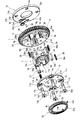
- FIG. 1 is an overall configuration diagram showing a first embodiment of a valve timing control device according to the present invention in cross section. It is a disassembled perspective view of the principal part in the valve timing control apparatus in this embodiment. It is effect
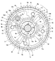
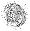
- action explanatory drawing which shows the state which rotated the vane member in this embodiment relatively to the most retarded angle side. It is the bird's-eye view which looked at the valve timing control device of this embodiment from the front.
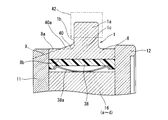
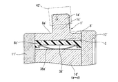
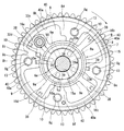
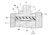
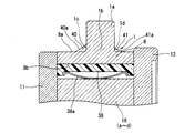
- It is a principal part expanded sectional view of the valve timing control apparatus of this embodiment. It is a principal part expanded sectional view in the conventional valve timing control apparatus. It is a front view which shows the state which removed the front plate in 2nd Embodiment of this invention. It is a principal part expanded sectional view in 3rd Embodiment of this invention. It is a principal part expanded sectional view in 4th Embodiment of this invention.
- the present invention is applied to the intake valve side of a multi-cylinder internal combustion engine having two intake valves and exhaust valves per cylinder.
- the valve timing control device As shown in FIG. 1 and FIG. 2, the valve timing control device (VTC) is a sprocket 1 that is a driving rotating body that is rotationally driven by a crankshaft (not shown) via a timing chain 42 that is an endless transmission member.
- a camshaft 2 on the intake side provided so as to be relatively rotatable with respect to the sprocket 1 and between the sprocket 1 and the camshaft 2 to convert the relative rotational phases of the both 1 and 2.
- a phase change mechanism 3 and a hydraulic circuit 4 that operates the phase change mechanism 3 are provided.
- the sprocket 1 is integrally formed with a housing body 8 of the housing 5 described later of the phase changing mechanism 3, it will be specifically described in the description of the housing 5.
- the camshaft 2 is rotatably supported by a cylinder head (not shown) via a cam bearing, and a pair of drive cams (not shown) having the same profile for opening and closing two intake valves per cylinder on the outer peripheral surface.
- a pair of drive cams (not shown) having the same profile for opening and closing two intake valves per cylinder on the outer peripheral surface.
- An insertion hole 2b is formed.
- a female screw 2c to which a male screw 6c formed at the tip of the cam bolt 6 is screwed is formed at the tip of the bolt insertion hole 2b.
- the phase changing mechanism 3 is fixed to a housing 5 having an operation chamber inside and a cam bolt 6 at one end of the camshaft 2 so as to be relatively rotatable in the housing 5. And a vane member 7 accommodated therein.
- the housing 5 includes a housing body 8 that is formed of a sintered metal in a cylindrical shape, a front plate 11 that closes a front end opening of the housing body 8 opposite to the camshaft 2, and a rear end on the camshaft 2 side. And a rear plate 12 that closes the opening.
- the housing body 8 is integrally formed of a sintered alloy in a cylindrical shape, and the sprocket 1 is integrally provided at a position slightly closer to the rear plate 12 from the center in the axial direction of the outer peripheral surface 8a.
- the four shoes 8c to 8f are integrally projected at substantially equal positions in the circumferential direction of the surface 8b.
- the sprocket 1 integrated with the housing main body 8 has a plurality of gear portions 1a integrally formed by winding the timing chain.
- the working chambers are retarded hydraulic chambers 9 and advanced hydraulic chambers, which are four retarded hydraulic chambers, respectively, by the respective shoes 8c to 8f and four vanes 16a to 16d described later of the vane member 7.
- the advance hydraulic chamber 10 is separated.
- the housing body 8, the front plate 11, and the sprocket 1 are fastened together by the four bolts 13 that pass through bolt insertion holes 8g that are formed through the shoes 8c to 8f.
- the housing body 8 is formed with two lightening portions 8h and 8i at portions where the bases of the first shoe 8c and the second shoe 8d having a relatively large width are located.
- Each of the lightening portions 8h and 8i is formed in a partial arc shape along the cylindrical shape of the housing body 8 so that the housing body 8 is reduced in weight and the entire housing body according to the different shapes of the shoes 8c to 8f. It is formed to balance the weight.
- a positioning groove 8j for positioning with a rear plate 12, which will be described later, is formed through the base portion of the first shoe 8c of the housing body 8 in the axial direction.
- the front plate 11 is formed of carbon steel in a disc shape, and a through hole 11a having a comparatively large diameter is formed through the center position thereof. Further, the front plate 11 is formed with four bolt insertion holes 11b through which the bolts 13 are inserted at equal circumferential positions on the outer peripheral portion.
- the front plate 11 has an outer end surface 11c formed in a flat shape, and an inner edge of a spiral spring 33 described later is brought into contact therewith.
- the outer end surface 11 c has a role as a seating surface of the spiral spring 33. Accordingly, the head 13a of each bolt 13 screwed into the bolt insertion hole 11b does not hinder the contact of the spiral spring 33 with the outer end surface 11c on the outer end surface 11c side of each bolt insertion hole 11b.
- a long groove-shaped counterbore portion 11d into which the base portion of the shaft portion of each bolt 13 is fitted is provided.
- the umbrella-equipped pin 14 includes a pin body 14a formed in a columnar shape, and a disk-shaped umbrella portion 14b provided on an end surface opposite to the press-fitting side of the pin body 14a.
- a second locking end 33c of a spiral spring 33 which will be described later, is wound around the pin body 14a and locked.
- the umbrella portion 14b is formed to have a diameter so as to cover substantially the entire axial end surface of the second locking end portion 33c wound around the pin body 14a, and the second portion of the spiral spring 33 is formed.
- the locking end portion 33 c is prevented from dropping from the outer end surface 11 c of the front plate 11.
- the rear plate 12 is formed with four female screw holes 12a into which the male screw portions 13c formed at the tips of the shaft portions 13b of the bolts 13 are screwed at substantially equal positions in the circumferential direction of the outer peripheral portion. Further, the outer peripheral portion of the rear plate 12 is engaged with the positioning groove 8j of the housing main body 8 in the axial direction at the time of assembling each component member, thereby positioning the housing body in the circumferential direction and the radial direction. A positioning hole 12b into which one end of the positioning pin 36 to be pressed is press-fitted is formed.
- the vane member 7 is integrally formed of a sintered metal material, and as shown in FIGS. 1 to 3, a rotor 15 having a bolt insertion hole 15a formed in the center in the axial direction and a circular shape on the outer peripheral surface of the rotor 15. It is composed of four first to fourth vanes 16a to 16d that project radially at approximately 90-equal intervals in the circumferential direction. Further, the vane member 7 has a camshaft 6 in which the rotor 15 is camshafted. The rotor 15 is formed in a substantially cylindrical shape, and the second positioning pin 37 is attached to the camshaft 2 by the cambolt 6 inserted through the bolt insertion hole 15a. The vane member 7 is attached to the one end portion 2a of the camshaft 2 in a cantilever state.
- a cylindrical projection 17 having the same axial center as that of the rotor 15 is integrally formed at a central position on the front end surface side of the rotor 15 on the front plate 11 side.
- the cylindrical protrusion 17 is formed in a substantially cylindrical shape, and protrudes forward from the front end surface of the rotor 15, and has an outer diameter of the through hole 11a of the front plate 11.
- the axial length is set to a predetermined size longer than the plate thickness of the front plate 11 and the axial spring width W1 of a spiral spring 33 described later. Has been. As a result, when the apparatus is assembled, the tip 17a side of the cylindrical protrusion 17 projects forward of the front plate 11 through the through hole 11a.
- the inner diameter of the cylindrical projection 17 is formed larger than the outer diameter of the head 6b of the cam bolt 6, and when the apparatus is assembled, the head 6b of the cam bolt 6 becomes the cylindrical projection. 17 is accommodated and arranged in the interior.
- a locking groove 18 for locking a first locking end portion 33b of a spiral spring 33 described later is provided on the end surface of the cylindrical projection portion 17 on the tip end portion 17a side.
- the locking groove 18 is notched in a substantially elongated rectangular shape along the axial direction from the proximal end side to the distal end edge at a predetermined position in the circumferential direction of the cylindrical protrusion 17.
- the opposing surface 18a on the side where the first locking end portion 33b is locked is formed as an arc surface.
- the rotor 15 is formed with a circular fitting groove 15b into which the one end portion 2a of the camshaft 2 is fitted on the rear end surface side, and the rear end surface is in contact with the opposing inner end surface of the rear plate 12. It comes in sliding contact with a minute side clearance between them.
- the front end surface of the rotor 15 is in sliding contact with the opposed inner end surface of the front plate 11 with a minute side clearance.
- each of the first to fourth vanes 16a to 16d is disposed between the shoes 8c to 8f, and has a seal groove formed on each arcuate outer peripheral surface.
- a seal member 38 that is slidably sealed on the inner peripheral surface 8b of the housing body 8 is fitted.
- a seal member 39 that slides and seals on the outer peripheral surface of the rotor 15 is fitted in the seal groove formed on the inner peripheral surface of the tip of each of the shoes 8c to 8f.
- the seal members 38 and 39 are urged toward the inner peripheral surface of the housing body 8 or the outer peripheral surface of the rotor 15 by metal arc springs 38a and 39a disposed on the inner side.
- the vanes 16a to 16d are slidably in contact with the inner end surface of the sprocket 1 and the inner end surface of the front plate 11 at both side surfaces in the width direction (rotor axial direction). A sealing function is exhibited between the inner end surface of the front plate 11 and the inner end surface of the rear plate 12.
- each of the vanes 16a to 16d is formed such that the first vane 16a has a fan-shaped maximum width when viewed from the side and is heaviest, and the three second to fourth vanes other than the first vane 16a are formed.
- the widths 16b to 16d are set to substantially the same width smaller than that of the first vane 16a.
- the other second to fourth vanes 16b to 16d are in a separated state without coming into contact with the opposing side surfaces of the shoes 8c and 8d whose both side surfaces face each other in the circumferential direction. Accordingly, the contact accuracy between the first vane 16a and the first and second shoes 8c and 8d is improved, and the supply speed of the hydraulic pressure to each of the retard and advance hydraulic chambers 9 and 10 is increased and the vane member.
- the rotational responsiveness in the forward / reverse direction of 7 increases.
- Each retarded hydraulic chamber 9 and each advanced hydraulic chamber 10 are respectively connected to the hydraulic circuit 4 via a first communication hole 9a and a second communication hole 10a formed in the rotor 15 along the radial direction. Communicate.
- the hydraulic circuit 4 selectively supplies or discharges hydraulic oil (hydraulic pressure) to or from each of the retard and advance hydraulic chambers 9 and 10, as shown in FIG.
- a retard oil passage 19 that supplies and discharges hydraulic pressure via the first communication hole 9a, and an advance oil that supplies and discharges hydraulic pressure to and from each advance hydraulic chamber 10 via the second communication hole 10a.
- the oil pump 21 is a general one such as a trochoid pump that is rotationally driven by an engine crankshaft.
- Each of the retard oil passage 19 and the advance oil passage 20 is connected at one end to the passage port of the electromagnetic switching valve 22, and the other end via an unillustrated cylinder head or cylinder block.
- the first communication hole 9a and the second communication hole 10a communicate with each other through the passage portion 20a.
- the retard passage portion 19a communicates with each retard hydraulic chamber 9 through the first communication hole 9a, while the advance passage portion 20a communicates with each advance through the second communication hole 10a. It communicates with the angular hydraulic chamber 10.
- the electromagnetic switching valve 22 is a 4-port 3-position valve, and an electronic controller 24 is provided with a spool valve body (not shown) provided in the valve body so as to be slidable in the axial direction. It is moved in the front-rear direction so that the discharge passage 21a of the oil pump 21 and one of the oil passages 19 and 20 are communicated with each other, and the other oil passage 19 or 20 and the drain passage 23 are communicated with each other. The oil passages 19 and 20 are closed.
- the suction passage 21b of the oil pump 21 and the drain passage 23 communicate with each other in the oil pan. Further, a filtration filter (not shown) is provided on the downstream side of the discharge passage 21a of the oil pump 21, and a main oil gallery M / M for supplying lubricating oil to a sliding portion of the internal combustion engine on the downstream side. G communicates. Further, the oil pump 21 is provided with a flow rate control valve (not shown) that discharges excess hydraulic oil discharged from the discharge passage 21a to the oil pan and controls it to an appropriate flow rate.
- the electronic controller 24 includes various sensors such as a crank angle sensor, an air flow meter, an engine water temperature sensor, a throttle valve opening sensor, and a cam angle sensor that detects the current rotation phase of the camshaft 2. To detect the current engine operating state and output a control pulse current to the coil of the electromagnetic switching valve 22 to control the movement position of each spool valve body, thereby Switching control is performed.
- various sensors such as a crank angle sensor, an air flow meter, an engine water temperature sensor, a throttle valve opening sensor, and a cam angle sensor that detects the current rotation phase of the camshaft 2.
- a lock mechanism 27 is provided between the first vane 16a and the rear plate 12 to restrain the vane member 7 at the most advanced position with respect to the housing 5.
- the lock mechanism 27 is slidably accommodated in a sliding hole 28 that is formed in the first vane 16a so as to penetrate therethrough in the axial direction.
- the lock pin 29 is formed so as to be freely movable back and forth, and is formed at a predetermined position in the center of the rear plate 12 in the radial direction.
- the lock hole engages with the tip 29a of the lock pin 29 to lock the vane member 7.
- 30 and an engagement / disengagement mechanism for engaging or disengaging the distal end portion 29a of the lock pin 29 with the lock hole 30 in accordance with the starting state of the engine.
- the lock pin 29 is formed in a substantially cylindrical shape including the tip end portion 29a, and is mounted between the bottom surface of the groove formed in the inner axial direction from the rear end side and the inner surface of the front plate 11.
- the coil spring 31 is biased in the advancing direction (engagement direction).
- the lock pin 29 is formed with an annular large-diameter portion that slides in the large-diameter hole of the sliding hole 28 on the outer periphery of the rear end portion, and the large-diameter portion and the large-diameter hole of the sliding hole 28 are connected to each other.
- An annular first pressure receiving chamber 32a which will be described later, is separated from the stepped portion.
- the lock hole 30 is formed to be larger than the outer diameter of the tip end portion of the lock pin 29, is formed at a position biased toward the retard hydraulic chamber 9 in the circumferential direction of the rear plate 12, and the lock pin When 29 is engaged, the relative conversion angle between the housing 5 and the vane member 7 is set to the most retarded position.
- a wear-resistant ring 30a is press-fitted and fixed to the inner peripheral surface of the lock hole 30.
- the ring 30a is formed with high hardness by carburizing, and the lock pin 29 is formed on the inner peripheral surface. Wear is suppressed even if the outer peripheral surface is repeatedly engaged and disengaged while being in sliding contact.
- the engagement / disengagement mechanism includes the coil spring 31 that urges the lock pin 29 in the advance direction, the first pressure receiving chamber 32a and the second pressure receiving chamber 32b formed on the bottom side of the lock hole 30, and the first 1 and a release hydraulic circuit that supplies hydraulic pressure to the second pressure receiving chambers 32a and 32b to retract the lock pin 29.
- the release hydraulic circuit is formed in an inclined shape in the head of the first vane 16a, and the first hydraulic pressure chamber 9 and the first pressure receiving chamber 32a communicate with each other.
- An oil hole 32c and a second oil hole 32d that is formed on the inner end surface of the rear plate 12 and communicates the one second communication hole 10a and the second pressure receiving chamber 32b. Accordingly, the hydraulic pressure selectively supplied to the retard hydraulic chamber 9 and the advanced hydraulic chamber 10 is supplied to the first and second pressure receiving chambers 32a and 32b via the first and second oil holes 32c and 32d.
- the lock pin 29 acts in the backward direction.
- the front end surface of the first vane 16a has an air vent groove 50 that allows air to escape from the back pressure chamber formed on the rear end side of the sliding hole 28 to the outside. It is formed along.
- a spiral spring 33 for urging the vane member 7 in the advance direction with respect to the housing 5 is mounted on the outer end surface 11c of the front plate 11 as shown in FIGS.
- the spiral spring 33 is a so-called spring spring, and is formed by winding a flat rectangular wire having a substantially rectangular cross section on the substantially same plane so that the surfaces in the longitudinal direction face each other.
- a spiral spring main body 33a having a shape that gradually increases in diameter toward the outer peripheral side, a first locking end 33b in which an innermost peripheral portion of the spiral spring main body 33a is bent radially inward, and the spiral
- the outer peripheral part of the spring main body 33a is comprised from the 2nd latching
- the first locking end portion 33b is locked and fixed to the arcuate facing surface 18a of the locking groove 18 of the cylindrical projection portion 17, while the second locking end portion 33c is fixed to the front plate 11. It is fixedly locked to the outer peripheral surface of the pin 14 with a bevel provided on the outer end surface 11c of the outer periphery of the vane member 7 so that the vane member 7 is always assisted in the rotational direction on the advance side by the spring force of the spiral spring 33. It has become. That is, when the vane member 7 rotates relative to the housing 5 relative to the retard side, the spiral spring 33 is deformed in the reduced diameter direction and urged toward the advance side, but this urging force is not large.
- the alternating torque generated in the camshaft 2 is substantially the same as the negative torque that converts the vane member 7 to the retard side, and the vane member 7 is unlocked by the lock mechanism 27. In the state, the vane member 7 is balanced at the intermediate position between the most retarded angle and the most advanced angle in cooperation with the negative torque.
- a support pin 34 is provided on the outer end surface 11c of the front plate 11 to assist the biasing operation of the spiral spring 33 by increasing the torque generated in the spiral spring 33.
- the support pin 34 is press-fitted and fixed at a position spaced a predetermined angle from the pin 14 with an umbrella, and the outermost peripheral portion of the spiral spring 33 is in contact with the outer peripheral surface thereof.
- annular groove 35 for accommodating the innermost peripheral portion 33d of the spiral spring 33 is provided on the outer peripheral surface of the cylindrical projection portion 17.
- the annular groove 35 is formed to have a predetermined groove width longer than the spring width W1 of the spiral spring 33, and the spiral spring 33 can be engaged therein.
- annular groove 35 is formed so that the groove depth is shallower than the spring thickness of the spiral spring 33, and when the innermost peripheral portion of the spiral spring 33 is engaged therein, the innermost peripheral portion is provided.
- the outer diameter side of the projection always protrudes (is exposed) from the annular groove 35.
- the spiral spring 33 since the spiral spring 33 has a shape that gradually increases in diameter from the inner peripheral side toward the outer peripheral side, the spiral spring 33 contacts the bottom surface of the annular groove 35 in the vicinity of the first locking end 33b. Although they are in contact with each other, they gradually move away from the bottom as they move toward the outer peripheral side.
- a built-up portion is formed between the outer peripheral surface 8a of the housing body 8 and one side surface 1c of the base end portion 1b of the gear portion 1a on the front plate 11 side. 40 is provided integrally.
- the said base end part 1b is a site
- the build-up portion 40 is formed together when the housing body 8 is formed by sintering, and as shown in FIGS. 2 to 5, of the base end portion 1b of the gear portion 1a of the sprocket 1 It is provided only on the one side surface 1c side of the front plate 11 side, and is formed over the entire circumferential direction including the respective thinned portions 8h, 8i of the housing body 8.
- the built-up portion 40 is formed on the bottom surface and the entire inner surface on the side of the lightening portion positions 8h and 8i.
- the built-up portion 40 has an outer surface 40a that is tapered downward from one side surface 1c of the sprocket 1, that is, from one side surface 1c of the base end 1b of the gear portion 1a toward the outer peripheral surface 8a of the housing body 8.
- the inclination angle with respect to the outer peripheral surface 8a of the housing body 8 is formed at an acute angle.
- the height H of the side surface 1c side of the built-up portion 40 is set to a height that does not hinder the winding of the timing chain 42.
- the extension line X of the taper angle of the outer surface 40a in the direction of the housing main body 8 does not go to the inner peripheral surface 8b of the housing main body 8, as shown in FIG.
- the inclination angle is set toward the front plate 11.
- each retarded hydraulic chamber 9 flows into each retarded hydraulic chamber 9 through the retarded oil passage 19, and each retarded hydraulic chamber 9 becomes high pressure
- the hydraulic oil in the advance hydraulic chamber 10 passes through the advance oil passage 20 and is discharged from the drain passage 23 into the oil pan, and the pressure in each advance hydraulic chamber 10 becomes low.
- the vane member 7 rotates to the left side (retard angle side) in the figure against the spring force of the spiral spring 33 as the volume of each retard angle hydraulic chamber 9 increases. Is maintained, and one side surface of the first vane 16a abuts against one side surface of the first shoe 8c facing from the circumferential direction, and the rotational position on the maximum retardation side is regulated.
- the vane member 7, that is, the camshaft 2 is maintained in a state in which the relative rotation angle is converted to the most retarded angle side with respect to the housing 5.
- spiral spring 33 is deformed in the reduced diameter direction because the vane member 7 rotates relative to the housing 5 toward the retard side.
- the vane member 7 rotates to the right side (advance angle side) in the figure by the combined force of the hydraulic pressure in each advance angle hydraulic chamber 10 and the spring force accompanying the diameter expansion deformation of the spiral spring 33, and the first
- the other side surface of the vane 16a abuts against the opposite one side surface of the second shoe 8d facing from the circumferential direction, and the rotational position on the maximum advance side is restricted.
- a built-up portion 40 is provided between one side surface 1 c of the sprocket 1, that is, one side surface 1 c on the front plate 11 side of the base end portion 1 b of the gear portion 1 a and the outer peripheral surface 8 a of the housing body 8. Since it provided, the bending rigidity of the base end part 1b becomes large in the gear part 1a.
- the housing 5 and the vane member 7 are cantilevered with the camshaft 2, and the engine is pulled from the timing chain 42 to each gear portion 1a in the direction of the crankshaft as the crankshaft rotates during engine driving. Even if a load in the direction acts and a moment in the crankshaft direction due to the timing chain is generated in the housing 5, the stress concentration on the front plate 11 side of the base end portion 1b of the gear portion 1a is sufficiently generated. Can be suppressed.
- the conventional valve timing control device described in the above publication has a pulling direction load (arrow in the figure) from the timing chain 42 to the crankshaft direction via the gear portion 1a ′.
- the gear portion 1a ' is directed toward the crankshaft (downward) with a portion (one side surface) on the front plate 11' side of the base end portion 1b 'of the gear portion 1a' as a fulcrum.
- the housing body 8 ′ will fall and be deformed as the rear plate 12 side rises due to the inclination.
- the seal is formed with the inner peripheral surface 8b' of the housing body 8 '. For example, a gap C of several microns may be generated between the member 38 'and the sealing function may be deteriorated.
- the rising deformation of the housing main body 8 ′ on the rear plate 12 ′ side may cause a decrease in the sealing performance between the axial end surface of the housing main body 8 ′ and the rear plate 12 ′ in contact with the one end surface. is there.
- the built-up portion 40 is provided on the one side surface 1c on the front plate 11 side of the base end portion 1b of the gear portion 1a, the base end portion of the gear portion 1a.
- the occurrence of stress concentration with respect to 1b is suppressed, the tilt toward the front plate 11 and the deformation of the housing body 8 are sufficiently suppressed, and the deterioration of the durability of the housing body 8 can be suppressed, and the seal on the front plate 11 side is suppressed.
- the uneven wear of the member 38 and the deterioration of the sealing performance on the rear plate 12 side can be suppressed.
- the build-up portion 40 has an outer surface 40a that is inclined downward from the gear portion 1a toward the outer peripheral surface 8a of the housing body 8, thereby ensuring rigidity and supporting beams for the gear portion 1a. Therefore, it is possible to effectively prevent the gear portion 1a from falling in the direction of the front plate 11.
- the extension line X of the taper angle of the outer surface 40a of the built-up portion 40 is in a direction avoiding the inner peripheral surface 8b of the housing main body 8, in other words, the housing main body in contact with the inner end surface of the front plate 11. 8 is within the thickness range excluding the outer peripheral surface 8a of the end face, the function as the support beam is further strengthened, and the deformation of the housing body 8 can be further suppressed. That is, when the extension line X of the taper angle of the outer surface 40a is applied to the inner peripheral surface 8b, there is a moment that the build-up portion 40 is inclined in the direction of the inner peripheral surface of the housing body 8 due to the load applied to the gear portion 1a.
- the function as a support beam becomes insufficient and the deformation of the housing body 8 cannot be suppressed, but if the direction is set so as not to intersect the inner peripheral surface 8b, the function as a support beam is enhanced. The deformation of the housing body 8 can be further suppressed.
- the build-up portion 40 is provided over the entire circumference including the lightening site positions 8h and 8i of the housing main body 8, the base end portion 1b and the rigidity of the entire housing main body 8 are provided on the gear portion 1a.
- the deformation of the housing body 8 in which the stress increases and stress concentration continuously occurs can be effectively suppressed over the entire circumference.
- the gear portion 1a of the sprocket 1 is provided not at the center in the axial direction of the outer peripheral surface 8a of the housing body 8 but at a position biased toward the rear plate 12 side. Since it can be formed largely to the side, the rigidity can be further increased.
- the outer peripheral surface 8a of the housing main body 8 is the outermost diameter portion of the built-up portion 40, that is, the meat, at a portion opposite to the built-up portion 40 with the gear portion 1a interposed therebetween. Since it is formed in a cylindrical shape having an outer diameter smaller than the root portion on the side of the gear portion 1a of the raised portion 40, the powder metal filling property at the portion becomes good at the time of the sintering molding, and the accuracy is high. Molding becomes possible.
- the housing body 8 when the base end portion 1b of the gear portion 1a is tilted in the direction of the crankshaft (downward) with the portion (one side surface) on the front plate 11 side as a fulcrum, this is accompanied.
- the housing body 8 also rises and deforms on the rear plate 12 side, but the rigidity on the rear plate 12 side is low, so that the influence of the falling of the gear portion 1a is reduced, and the housing body 8 is lifted on the rear plate 12 side. Deformation can be suppressed. That is, by making such a setting, it is possible to further suppress the floating deformation of the housing body 8 on the rear plate 12 side.
- the outer diameter of the outer peripheral surface 8 a of the housing body 8 is substantially the same except for the gear portion 1 a and the built-up portion 40.
- annular groove 35 is formed at the tip end portion 17 a of the cylindrical projection 17 integrally provided on the front end surface side of the rotor 15, and the spiral spring 33 is disposed at the innermost end of the annular groove 35. Since a part of the inner peripheral portion is engaged, the spiral spring 33 is opposite to the front plate 11 of the spiral spring 33 when the spiral spring 33 tries to move from the outer end surface 11c of the front plate 11 to the front side of the apparatus at the time of expansion / contraction deformation. The end face on the side comes into contact with one side wall surface 35b of the annular groove 35, and the falling of the spiral spring 33 from the front of the device is restricted.
- the annular groove 35 for engaging the innermost peripheral portion of the spiral spring 33 is provided in the vane member 7 itself, the number of parts can be reduced as compared with the case where another part is provided, and the manufacturing is performed. Work and assembly work can be facilitated, and costs associated with these can be reduced.
- the spiral spring 33 since the second locking end portion 33c of the spiral spring 33 is locked to the pin 14 with the umbrella, the spiral spring 33 is prevented from dropping from the front of the apparatus also by the umbrella portion 14b. Can be regulated.
- the annular groove 35 in the present embodiment is formed so that only a part of the innermost peripheral portion of the spiral spring 33 is engaged inside, the spiral spring 33 moves forward of the apparatus, and the annular groove 35. Even if it comes into contact with one side wall surface, the contact area is very small, so that the friction that can occur between the spiral spring 33 and one side wall surface of the annular groove 35 can be greatly reduced. .
- the annular groove 35 is formed over substantially the entire circumferential direction of the cylindrical protrusion 17, but it is not always necessary to form the entire circumference, and at least the spiral spring 33. It is only necessary to be formed in a range necessary for regulating the drop-out from the front of the apparatus, that is, in a predetermined circumferential range.
- FIG. 7 shows a second embodiment of the present invention, in which the build-up portion 40 is not provided on the outer periphery of the base portion of the four shoes 8c to 8f, not on the entire periphery of the housing body 8 on the front plate 11 side. Four are provided separately in the other four locations.
- each of the built-up portions 40 has a tapered outer surface 40a and the like that are the same as the structure of the first embodiment, but the housing body 8 avoids the outer periphery of the base of each of the shoes 8c to 8f having a high formation position.
- the built-up portion 40 is divided into four parts instead of the entire circumference of the housing body 8, the gear part 1 a and the housing body 8 are deformed to the front plate 11 side.
- the weight of the entire housing main body 8 can be reduced as well as being able to be sufficiently suppressed.
- FIG. 8 shows a second embodiment of the present invention, and the basic configuration such as the formation position of the gear portion 1a with respect to the outer peripheral surface 8a of the housing body 8 is the same as that of the first embodiment, but the outer surface 40a of the built-up portion 40 is the same. It is formed in a stepped protruding shape instead of a tapered shape. That is, the build-up portion 40 is formed in a stepped rectangular shape that is formed in a rectangular cross section and protrudes toward the front plate 11 side.
- this embodiment can also suppress the collapse and deformation of the gear portion 1a and the housing body 8 toward the front plate 11 side by the build-up portion 40, and in particular, the build-up portion 40 has a rectangular cross section. Since the volume is increased by increasing the rigidity, the rigidity is further increased.
- FIG. 9 shows a third embodiment, and the formation position of the sprocket 1 (gear portion 1a) is closer to the front plate 11 in the axial direction of the outer peripheral surface 8a of the housing body 8 than in the first embodiment.
- a second build-up portion 41 is provided.
- the first build-up portion 40 has basically the same structure as that of the first embodiment, but the second build-up portion 41 is smaller in size than the first build-up portion 40. Yes.
- the rigidity on both sides of the base end portion 1b of the gear portion 1a is increased by the first and second build-up portions 40 and 41. Therefore, the gear portion 1a associated with the tensile load by the timing chain 42 is provided. It is possible to more effectively suppress the collapse of the housing and the deformation of the housing body 8.
- first and second build-up portions 40 and 41 are formed over the entire circumference of the housing body 8, but can be provided intermittently as in the second embodiment. It is.
- the present invention is not limited to the configuration of each of the above-described embodiments, and can be similarly applied to only the exhaust valve side or both valve gears as the valve timing control device in addition to the intake valve side. It is.
- timing sprocket In addition to the timing sprocket, it can also be applied to a timing pulley around which an endless timing belt is wound.
- valve timing control device for an internal combustion engine based on the embodiment described above, for example, the following modes can be considered.
- the valve timing control device has a cylindrical housing body with a plurality of shoes projecting on the inner peripheral surface, and a base end portion integrally provided on the outer peripheral surface of the housing main body, and transmits the rotational force of the crankshaft.
- a vane member having a plurality of vanes separated into an advance oil chamber, a rear plate for closing one side opening on the camshaft side in the axial direction of the housing body, and a side of the housing body opposite to the camshaft
- a front plate that closes the other side opening, and at least a side surface on the front plate side of a base end portion of each gear portion and an outer peripheral surface of the housing body. It has a built-up portion that is, a.
- the build-up portion has an outer surface tapered from the side surface of the base end portion of each gear portion toward the outer peripheral surface of the housing body.
- the gear portion is provided on the rear plate side with respect to the axial center position of the housing body.
- the build-up portion is provided only between the outer peripheral surface of the housing body and the side surface on the front plate side of the base end portion of each gear portion.
- the housing main body and the gear portion are integrally formed by sintering molding, and the outer peripheral surface on the opposite side to the build-up portion sandwiching the gear portion in the rotation axis direction of the housing main body is a cylinder. It is formed in a planar shape.
- an inclined extension line from the gear portion side of the tapered outer surface of the built-up portion toward the outer peripheral surface of the housing main body is set so as not to intersect the inner peripheral surface of the housing main body.
- the build-up portion is provided over the entire circumference of the base end portion of each gear portion and the outer peripheral surface of the housing body.
- the build-up portion has an acute angle formed between the tapered outer surface and the outer peripheral surface of the housing body.
- each vane is provided with a seal member in sliding contact with the inner peripheral surface of the housing main body at the outer peripheral portion.
- a portion of the outer peripheral surface of the housing main body that overlaps with the plurality of shoes in the radial direction is formed with a hollow portion recessed inward in the radial direction, and the meat is also formed on the outer surface of the thin portion.
- a heap is provided.
- the build-up portion is provided on the bottom surface and the inner side surface of the meat removal portion.
- the housing main body includes a positioning pin provided on one side of the housing main body and the rear plate, a positioning groove provided on the other side of the both, and the positioning pin engaging from the axial direction. Are positioned with respect to the rear plate.
- a second build-up portion is also provided on the outer peripheral surface of the housing main body and the rear plate side of the base end portion of the gear portion.
- a cylindrical shape in which a plurality of shoes project from the inner peripheral surface and a gear portion around which a transmission member for transmitting the rotational force of the crankshaft is wound is integrally provided on the outer peripheral surface.
- the housing body is fixed to one end of the camshaft in the axial direction and is relatively rotatably provided in the housing body.
- the working chamber cooperates with the shoes to form the working oil chamber and the advance oil.
- a vane member having a plurality of vanes separated into a chamber, and an outer peripheral surface of the housing main body and at least a side surface on the side opposite to the camshaft of a base end portion of the gear portion coupled to the outer peripheral surface. And a built-up portion.
- the housing main body has higher rigidity on the side opposite to the camshaft than the rigidity on the camshaft side across the gear portion.
Landscapes
- Engineering & Computer Science (AREA)
- General Engineering & Computer Science (AREA)
- Mechanical Engineering (AREA)
- Chemical & Material Sciences (AREA)
- Combustion & Propulsion (AREA)
- Valve Device For Special Equipments (AREA)
Abstract
基端部1bがハウジング本体の外周面8aに一体に結合され、クランクシャフトの回転力を伝達するタイミングチェーン42が巻回される複数の歯車部1aと、カムシャフト2の一端部2aに固定されていると共にハウジング本体内に相対回転自在に設けられ、ロータ15の外周に、遅角油室と進角油室に隔成する4枚のベーン16a~16dを有するベーン部材7と、各歯車部の基端部の少なくともフロントプレート11側の一側面1cとハウジング本体の外周面との間に、外面40aがフロントプレート側に向かって下り傾斜状の肉盛り部40が設けられている。この肉盛り部によって歯車部の基端部の剛性を高めてハウジング本体の耐久性を向上させることができる。
Description
本発明は、吸気弁や排気弁の閉開タイミングを運転状態に応じて可変制御する内燃機関のバルブタイミング制御装置に関する。
従来の内燃機関のバルブタイミング制御装置としては、例えば以下の特許文献1に記載されたものが知られている。
このバルブタイミング制御装置は、外周面にクランクシャフトから回転力を伝達するタイミングチェーンが巻回された歯車部(スプロケット)が一体に形成されてなる円筒状のハウジング本体及びこのハウジング本体の前端開口部と後端開口をそれぞれ閉塞するフロントプレート及びリアプレートとからなるハウジングと、前記ハウジング本体内に相対回転自在に設けられ、前記ハウジング本体の内周面に突設された複数のシューとの間に複数の遅角油室と進角油室を隔成する複数のベーンを一体に有するベーン部材と、を備えている。
前記ベーン部材は、吸気側のカムシャフトの軸方向の一端部にカムボルトによって固定されていると共に、前記各遅角油室と各進角油室に対して油圧回路から選択的に給排された作動油によって、前記ハウジングに対して遅角側あるいは進角側へ相対回転して前記カムシャフトを介して吸気弁の開閉タイミングを機関運転状態によって制御するようになっている。
しかしながら、前記ベーン部材とハウジングは、カムシャフトの一端部に片持ち状態に支持されていることから、前記タイミングチェーンからの荷重がスプロケットの歯車部に作用すると、ハウジングが歯車部を介して傾いてしまうおそれがある。
このため、前記タイミングチェーンが巻回された歯車部の一部に、例えばフロントプレート側への倒れ方向にモーメントが作用して歯車部とハウジング本体の結合箇所、つまり歯車部の付け根部(基端部)の前記フロントプレート側に応力集中が継続的に発生し易くなる。この結果、ハウジング本体の耐久性が低下するおそれがある。
本発明は、前記従来のバルブタイミング制御装置の技術的課題に鑑みて案出されたもので、肉盛り部によって歯車部の基端部の剛性を高めてハウジング本体の耐久性を向上し得るバルブタイミング制御装置を提供することを目的としている。
本発明は、内周側に複数のシューが突設された円筒状のハウジング本体と、基端部が前記ハウジング本体の外周面に一体に設けられ、クランクシャフトの回転力を伝達する伝達部材が巻回される複数の歯車部と、カムシャフトの軸方向の一端部に固定されると共に前記ハウジング本体の内部に相対回転自在に設けられ、前記各シューの間を遅角油室と進角油室に隔成する複数のベーンを有するベーン部材と、前記ハウジング本体の軸方向の前記カムシャフト側の一方側開口を閉塞するリアプレートと、前記ハウジング本体の前記カムシャフトと反対側の他方側開口を閉塞するフロントプレートと、前記歯車部の基端部の少なくとも前記フロントプレート側の側面と前記ハウジング本体の外周面との間に設けられた肉盛り部と、を有していることを特徴としている。
本発明によれば、肉盛り部によって歯車部の基端部の剛性を高めてハウジング本体の耐久性を向上させることができる。
以下、本発明に係る内燃機関のバルブタイミング制御装置の実施形態を図面に基づいて詳述する。本実施形態では、一気筒当たりそれぞれ2つの吸気弁と排気弁を有する多気筒内燃機関の吸気弁側に適用したものを示している。
〔第1実施形態〕
前記バルブタイミング制御装置(VTC)は、図1及び図2に示すように、図外のクランクシャフトにより無端状の伝達部材であるタイミングチェーン42を介して回転駆動される駆動回転体であるスプロケット1と、該スプロケット1に対して相対回転可能に設けられた吸気側のカムシャフト2と、前記スプロケット1とカムシャフト2との間に配置されて、該両者1、2の相対回転位相を変換する位相変更機構3と、該位相変更機構3を作動させる油圧回路4と、を備えている。
〔第1実施形態〕
前記バルブタイミング制御装置(VTC)は、図1及び図2に示すように、図外のクランクシャフトにより無端状の伝達部材であるタイミングチェーン42を介して回転駆動される駆動回転体であるスプロケット1と、該スプロケット1に対して相対回転可能に設けられた吸気側のカムシャフト2と、前記スプロケット1とカムシャフト2との間に配置されて、該両者1、2の相対回転位相を変換する位相変更機構3と、該位相変更機構3を作動させる油圧回路4と、を備えている。
前記スプロケット1は、前記位相変更機構3の後述するハウジング5のハウジング本体8と一体に構成されていることから、ハウジング5の説明の中で具体的に述べる。
前記カムシャフト2は、図外のシリンダヘッドにカム軸受を介して回転自在に支持され、外周面には一気筒当たり2つの吸気弁を開閉作動させる同じプロフィールを有する各一対の駆動カム(図示せず)が軸方向の所定位置に一体に固定されていると共に、一端部2a側の内部軸心方向には、後述するベーン部材7を軸方向から固定するカムボルト6の軸部6aが挿通するボルト挿通孔2bが形成されている。なお、このボルト挿通孔2bの先端部には、カムボルト6の先端に形成された雄ねじ6cが螺着する雌ねじ2cが形成されている。
前記位相変更機構3は、図1~図3に示すように、内部に作動室を有するハウジング5と、前記カムシャフト2の一端部にカムボルト6によって固定されて、前記ハウジング5内に相対回転自在に収容されたベーン部材7と、を備えている。
前記ハウジング5は、焼結金属によって円筒状に形成されたハウジング本体8と、このハウジング本体8の前記カムシャフト2と反対側の前端開口を閉塞するフロントプレート11と、カムシャフト2側の後端開口を閉塞するリアプレート12と、から構成されている。
前記ハウジング本体8は、焼結合金によって円筒状に一体に形成され、外周面8aの軸方向の中央からやや前記リアプレート12寄りの位置に、スプロケット1が一体に設けられていると共に、内周面8bの円周方向のほぼ等間隔位置には前記4つのシュー8c~8fが一体に突設されている。
前記ハウジング本体8と一体のスプロケット1は、前記タイミングチェーンが巻回され複数の歯車部1aを一体に有している。
また、この各シュー8c~8fと前記ベーン部材7の後述する4枚のベーン16a~16dとによって前記作動室がそれぞれ4つの遅角油室である遅角油圧室9と進角油室である進角油圧室10が隔成されている。
前記ハウジング本体8とフロントプレート11及びスプロケット1とは、前記各シュー8c~8fにそれぞれ貫通形成されたボルト挿通孔8gを貫通する4本の前記ボルト13によって共締め固定されている。
前記ハウジング本体8は、横幅の比較的大きな前記第1シュー8cと第2シュー8dの各基部が位置する部位に、2つの肉抜き部位8h、8iが形成されている。この各肉抜き部位8h、8iは、ハウジング本体8の円筒形状に沿って部分的な円弧状に形成されて、ハウジング本体8の軽量化とシュー8c~8fの異なる形状に伴うハウジング本体の全体の重量バランスを取るために形成されている。
前記ハウジング本体8の第1シュー8cの基部には、後述するリアプレート12との位置決めを行う位置決め用溝8jが軸方向に貫通形成されている。
前記フロントプレート11は、炭素鋼によって円盤状に形成されると共に、その中央位置には、比較大径な貫通孔11aが貫通形成されている。また、フロントプレート11は、外周部の円周方向等間隔位置に、前記ボルト13が挿通する4つのボルト挿通孔11bが貫通形成されている。
さらに、前記フロントプレート11は、その外端面11cが平坦状に形成され、後述する渦巻ばね33の内側縁が当接されるようになっている。つまり、前記外端面11cは、渦巻ばね33の座面としての役割を有している。これに伴い、前記ボルト挿通孔11bに螺着する各ボルト13の頭部13aが、外端面11cに対する渦巻ばね33の当接を妨げないように、前記各ボルト挿通孔11bの外端面11c側の孔縁には、前記各ボルト13の軸部の付け根部が嵌合する長溝状のザグリ部11dがそれぞれ設けられている。
また、前記フロントプレート11の外端面11cの外周側には、図1、図2及び図4に示すように、傘付ピン14が軸方向から圧入固定されている。この傘付ピン14は、円柱状に形成されたピン本体14aと、該ピン本体14aの圧入側と反対側の端面に設けられた円板状の傘部14bと、から構成されており、前記ピン本体14aには、後述する渦巻ばね33の第2係止端部33cが巻回されて係止されるようになっている。
前記傘部14bは、前記ピン本体14aに巻回された前記第2係止端部33cの軸方向端面のほぼ全体を覆うような径を有して形成されて、前記渦巻ばね33の第2係止端部33cがフロントプレート11の外端面11cから脱落するのを規制している。
前記リアプレート12は、外周部の周方向のほぼ等間隔位置に前記ボルト13の軸部13b先端に形成された雄ねじ部13cが螺着する4つの雌ねじ孔12aが形成されている。また、このリアプレート12の外周部には、各構成部材の組付時において、前記ハウジング本体8の位置決め用溝8jに軸方向から係入してハウジング本体との周方向及び径方向の位置決めを行う位置決めピン36の一端部が圧入される位置決め用孔12bが穿設されている。
前記ベーン部材7は、焼結金属材によって一体に形成され、図1~図3に示すように、軸方向中央にボルト挿通孔15aが形成されたロータ15と、該ロータ15の外周面に円周方向のほぼ90ー等間隔位置に放射状に突設された4枚の第1~第4ベーン16a~16dと、から構成されている。また、このベーン部材7は、前記ロータ15がカムボルト6によってカムシャフト
前記ロータ15は、ほぼ円筒状に形成され、前記ボルト挿通孔15a挿通された前記カムボルト6によってカムシャフト2に第2位置決めピン37を介して位置決めされつつ固定されて、ベーン部材7がカムシャフト2の一端部2aに片持ち状態で取り付けられている。
前記ロータ15は、ほぼ円筒状に形成され、前記ボルト挿通孔15a挿通された前記カムボルト6によってカムシャフト2に第2位置決めピン37を介して位置決めされつつ固定されて、ベーン部材7がカムシャフト2の一端部2aに片持ち状態で取り付けられている。
また、ロータ15の前記フロントプレート11側の前端面側の中央位置には、該ロータ15と軸心を同じくする筒状突起部17が一体形成されている。この筒状突起部17は、図1~図4に示すように、ほぼ円筒状に形成され、ロータ15の前端面から前方へ突設され、その外径が、前記フロントプレート11の貫通孔11aの内径よりも僅かに小径に設定されると共に、その軸方向の長さが、前記フロントプレート11の板厚及び後述する渦巻ばね33の軸方向のばね巾W1よりも長い所定の大きさに設定されている。これにより、装置を組み付けた際に、前記筒状突起部17の先端部17a側が前記貫通孔11aを介してフロントプレート11の前方へ突出するようになっている。
また、前記筒状突起部17の内径は、前記カムボルト6の頭部6bの外径よりも大径に形成されており、装置を組み付けた際に、カムボルト6の頭部6bが筒状突起部17の内部へ収容配置されるようになっている。
また、前記筒状突起部17の先端部17a側の端面には、後述する渦巻ばね33の第1係止端部33bが係止される係止溝18が設けられている。
この係止溝18は、図2及び図4に示すように、前記筒状突起部17の周方向の所定位置でかつ、基端側から先端縁に軸方向に沿ってほぼ細長い矩形状に切欠形成されると共に、周方向の対向面のうち、前記第1係止端部33bが係止する側の対向面18aが円弧面に形成されている。
また、ロータ15は、後端面側に前記カムシャフト2の一端部2aが嵌合する円形状の嵌合溝15bが形成されていると共に、後端面が前記リアプレート12の対向する内端面との間に微小なサイドクリアランスをもって摺接するようになっている。一方、ロータ15の前端面が前記フロントプレート11の対向する内端面に微小なサイドクリアランスをもって摺接するようになっている。
前記第1~第4ベーン16a~16dは、図2及び図3に示すように、それぞれが各シュー8c~8fの間に配置されていると共に、円弧状の各外周面に形成されたシール溝内に、ハウジング本体8の内周面8bに摺動しつつシールするシール部材38がそれぞれ嵌着されている。一方、前記各シュー8c~8fの先端内周面に形成されたシール溝には、ロータ15の外周面に摺動しつつシールするシール部材39がそれぞれ嵌着されている。なお、前記各シール部材38,39は、それぞれ内側に配置された金属製の円弧状ばね38a、39aによってハウジング本体8の内周面方向またはロータ15の外周面方向に付勢されている。
前記各ベーン16a~16dは、幅方向(ロータ軸方向)の各両側面が前記スプロケット1の内端面とフロントプレート11の内端面に対してそれぞれ微小なサイドクリアランスをもって摺接しており、同じく、前記フロントプレート11の内端面とリアプレート12の内端面との間でシール機能を発揮している。
また、前記各ベーン16a~16dは、第1ベーン16aが側面からみて扇状の最大巾に設定されて、最も重量が重く形成され、該第1ベーン16a以外の3枚の第2~第4ベーン16b~16dの巾が第1ベーン16aよりも小さいほぼ同一の巾に設定されている。
また、前記ベーン部材7は、最遅角側へ相対回転すると、図3に示すように、第1ベーン16aの一側面が周方向から対向する前記第1シュー8cの対向一側面に当接して最大遅角側の回転位置が規制されるようになっている。その一方で、図2に示すように、最進角側へ相対回転すると、第1ベーン16aの他側面が周方向から対向する第2シュー8dの対向一側面に当接して最大進角側の回転位置が規制されるようになっている。これら第1ベーン16aと第1、第2シュー8c、8dがベーン部材7の最遅角位置と最進角位置を規制するストッパとして機能するようになっている。
このとき、他の第2~第4ベーン16b~16dは、両側面が円周方向から対向する各シュー8c、8dの対向側面に当接せずに離間状態にある。したがって、第1ベーン16aと第1、第2シュー8c、8dとの当接精度が向上すると共に、前記各遅角、進角油圧室9,10への油圧の供給速度が速くなってベーン部材7の正逆方向の回転応答性が高くなる。
前記各遅角油圧室9と各進角油圧室10は、前記ロータ15の内部に径方向に沿って形成された第1連通孔9aと第2連通孔10aを介して前記油圧回路4にそれぞれ連通している。
前記油圧回路4は、前記各遅角、進角油圧室9,10に対して作動油(油圧)を選択的に供給あるいは排出するもので、図1に示すように、各遅角油圧室9に対して前記第1連通孔9aを介して油圧を給排する遅角油通路19と、各進角油圧室10に対して前記第2連通孔10aを介して油圧を給排する進角油通路20と、該各油通路19,20に作動油を供給するオイルポンプ21と、機関の作動状態に応じて前記遅角油通路19と進角油通路20の流路を切り換える電磁切換弁22と、を備えている。前記オイルポンプ21は、機関のクランクシャフトによって回転駆動するトロコイドポンプなどの一般的なものである。
前記遅角油通路19と進角油通路20とは、それぞれの一端部が前記電磁切換弁22の通路ポートに接続されている一方、各他端部側が図外のシリンダヘッドやシリンダブロックを介して前記カムボルト6の軸部6a外周面とボルト挿通孔2bとの間に形成された遅角通路部19aと、カムシャフト2の一端部2a側の内部に軸方向に沿って形成された進角通路部20aとを介して前記第1連通孔9a、第2連通孔10aにそれぞれ連通している。
前記遅角通路部19aは、前記第1連通孔9aを介して前記各遅角油圧室9に連通している一方、進角通路部20aは、前記第2連通孔10aを介して前記各進角油圧室10に連通している。
前記電磁切換弁22は、図1に示すように、4ポート3位置の弁であって、電子コントローラ24によって、バルブボディ内に軸方向へ摺動自在に設けられた図外のスプール弁体を前後方向に移動させて、オイルポンプ21の吐出通路21aと前記いずれかの油通路19,20と連通させると同時に、該他方の油通路19,20とドレン通路23とを連通させるか、または各油通路19,20を閉止させるようになっている。
前記オイルポンプ21の吸入通路21bと前記ドレン通路23とは、オイルパン内に連通している。また、オイルポンプ21の前記吐出通路21aの下流側には、図外の濾過フィルタが設けられていると共に、この下流側で内燃機関の摺動部などに潤滑油を供給するメインオイルギャラリーM/Gに連通している。さらに、オイルポンプ21は、吐出通路21aから吐出された過剰な作動油をオイルパンに排出して適正な流量に制御する図外の流量制御弁が設けられている。
前記電子コントローラ24は、内部のコンピュータが図外のクランク角センサやエアフローメータ、機関水温センサ、スロットルバルブ開度センサ及びカムシャフト2の現在の回転位相を検出するカム角センサなどの各種センサ類からの情報信号を入力して現在の機関運転状態を検出すると共に、電磁切換弁22のコイルに制御パルス電流を出力してそれぞれのスプール弁体の移動位置を制御し、これによって、前記各通路を切り換え制御するようになっている。
また、前記第1ベーン16aと前記リアプレート12との間には、前記ハウジング5に対してベーン部材7を最進角位置に拘束するロック機構27が設けられている。
このロック機構27は、図1~図3に示すように、前記第1ベーン16aの内部に軸方向に貫通形成された摺動用孔28に摺動自在に収容されて、リアプレート12側に対して進退自在に設けられたロックピン29と、前記リアプレート12の径方向のほぼ中央所定位置に形成され、前記ロックピン29の先端部29aが係合して前記ベーン部材7をロックするロック穴30と、機関の始動状態に応じて前記ロックピン29の先端部29aをロック穴30に係合あるいは係合を解除する係脱機構と、から構成されている。
前記ロックピン29は、先端部29aを含めたほぼ全体が円柱状に形成されていると共に、後端側から内部軸方向に形成された凹溝底面とフロントプレート11の内面との間に弾装された、コイルスプリング31によって進出方向(係合方向)へ付勢されている。また、ロックピン29は、後端部外周に摺動用孔28の大径孔に摺動する円環状の大径部が形成されて、この大径部と摺動用孔28の大径孔との段差部に後述する円環状の第1受圧室32aを隔成するようになっている。
前記ロック穴30は、前記ロックピン29の先端部外径よりも大きく形成され、リアプレート12の円周方向の前記遅角油圧室9側に偏倚した位置に形成されていると共に、前記ロックピン29が係合した場合には、前記ハウジング5とベーン部材7の相対変換角度が最遅角側の位置となるように設定されている。また、このロック穴30の内周面には、耐摩耗性のリング30aが圧入固定されており、このリング30aは、浸炭加工によって高硬度に形成されて、内周面に前記ロックピン29の外周面が摺接しながら繰り返し係脱しても摩耗が抑制されるようになっている。
前記係脱機構は、前記ロックピン29を進出方向へ付勢する前記コイルスプリング31と、前記第1受圧室32a及び前記ロック穴30の底部側に形成された第2受圧室32bと、該第1、第2受圧室32a、32bに油圧を供給してロックピン29を後退させる解除用油圧回路とから構成されている。
前記解除用油圧回路は、図2及び図3に示すように、第1ベーン16aの頭部内に傾斜状に形成されて、前記遅角油圧室9と第1受圧室32aを連通させる第1油孔32cと、リアプレート12の内端面に形成されて、前記一つの第2連通孔10aと第2受圧室32bとを連通させる第2油孔32dとを有している。したがって、前記遅角油圧室9と進角油圧室10にそれぞれ選択的に供給された油圧が第1、第2油孔32c、32dを介して第1、第2受圧室32a、32bに供給されて前記ロックピン29に後退方向へ作用するようになっている。
なお、前記第1ベーン16a前端面には、図1及び図3に示すように、前記摺動用孔28の後端側に形成された背圧室から外部へ空気を逃がす空気抜き溝50が径方向に沿って形成されている。
また、前記フロントプレート11の外端面11cには、図1~図4に示すように、前記ベーン部材7をハウジング5に対して進角方向へ付勢する渦巻ばね33が装着されている。
前記渦巻ばね33は、いわゆるゼンマイばねであって、横断面ほぼ長方形状の扁平な角線を、長手方向の面が対向するようにほぼ同一平面上にて巻回させてなり、内周側から外周側にかけて徐々に拡径する形状を有する渦巻ばね本体33aと、該渦巻ばね本体33aの最内周部を径方向内側に湾曲状に折曲させた第1係止端部33bと、前記渦巻ばね本体33aの最外周部を径方向外側に半円フック状に湾曲させた第2係止端部33cと、から構成されている。
前記第1係止端部33bは、前記筒状突起部17の係止溝18の円弧状の対向面18aに係止固定されている一方、前記第2係止端部33cは、フロントプレート11の外端面11cに設けられた前記傘付ピン14の外周面に係止固定されており、この渦巻ばね33のばね力によって、前記ベーン部材7を進角側の回転方向へ常時アシストするようになっている。すなわち、この渦巻ばね33は、前記ベーン部材7がハウジング5に対して遅角側へ相対回転した場合に縮径方向へ変形して進角側へ付勢するが、この付勢力は大きなものではなく、前記カムシャフト2に発生する交番トルクのうち、ベーン部材7を遅角側に変換させる負のトルクとほぼ同じ程度のものであって、ベーン部材7がロック機構27によるロックが解除された状態では前記負のトルクと協働してベーン部材7を最遅角と最進角の中間位置にバランスさせるようになっている。
さらに、前記フロントプレート11の外端面11cには、前記渦巻ばね33に生じるトルクを増大させることで、該渦巻ばね33の付勢動作を補助するサポートピン34が設けられている。
このサポートピン34は、前記傘付ピン14から所定角度を隔てた位置に圧入固定されていると共に、その外周面には、渦巻ばね33の最外周部が当接されている。これにより、渦巻ばね33が縮径方向へ変形した際に、渦巻ばね33のサポートピン34との当接位置から第2係止端部33cの間に生じるトルクを増大させるようになっている。
また、前記筒状突起部17の外周面には、渦巻ばね33の最内周部33dを内部に収容する環状溝35が設けられている。この環状溝35は、前記渦巻ばね33のばね巾W1よりも長尺な所定の溝巾に形成されて、内部に渦巻ばね33を係入可能としている。
さらに、前記環状溝35は、その溝深さが、前記渦巻ばね33のばね厚さよりも浅く形成されて、内部に渦巻ばね33の最内周部を係入した際に、該最内周部の外径側が常に環状溝35からはみ出す(露出する)ようになっている。
このとき、前記渦巻ばね33は、内周側から外周側へ向かうにつれて徐々に拡径する形状を有していることから、第1係止端部33b付近においては前記環状溝35の底面と当接しているものの、外周側へ向かうにつれて該底面から徐々に離間するようになっている。
そして、本実施形態では、図2~図5に示すように、前記ハウジング本体8の外周面8aと歯車部1aの基端部1bのフロントプレート11側の一側面1cとの間に肉盛り部40が一体に設けられている。なお、前記基端部1bは、歯車部1aの前記タイミングチェーン42が噛み合う歯先先端部分を除いた部位である。
前記肉盛り部40は、ハウジング本体8を焼結成形する際に一緒に成形されるものであって、図2~図5に示すように、スプロケット1の歯車部1aの基端部1bのうちフロントプレート11側の一側面1c側のみに設けられていると共に、ハウジング本体8の前記各肉抜き部位8h、8iを含めた円周方向全体に渡って形成されている。この肉盛り部40は、前記肉抜き部位位8h、8i側では、その底面と内側面全体に形成されている。
また、この肉盛り部40は、その外面40aがスプロケット1の一側面1c、つまり歯車部1aの基端部1bの一側面1cからハウジング本体8の外周面8aに向かって下り傾斜のテーパ状に形成され、そのハウジング本体8の外周面8aに対する傾斜角度が鋭角に形成されている。また、肉盛り部40は、前記一側面1c側の高さHがタイミングチェーン42の巻回に支障のない高さに設定されている。
また、前記外面40aのテーパ角度のハウジング本体8方向への延長線Xは、図5に示すように、前記ハウジング本体8の内周面8bに向かうことなく、つまり内周面8bにかかることなくフロントプレート11方向に向かった傾斜角度に設定されている。
〔本実施形態の作用効果〕
まず、機関停止時にイグニッションスイッチをオフ操作すると、カムシャフト2は交番トルクの大きな負のトルクによって、渦巻ばね33のばね力に抗してベーン部材7を最大遅角位置に付勢すると共に、この位置でロックピン29の先端部29aがロック穴30内に係入して、ベーン部材7を始動に最適な遅角側の相対回転位置に拘束する。このため、吸気弁は、開閉タイミングが最遅角側へ安定的に保持される。
〔本実施形態の作用効果〕
まず、機関停止時にイグニッションスイッチをオフ操作すると、カムシャフト2は交番トルクの大きな負のトルクによって、渦巻ばね33のばね力に抗してベーン部材7を最大遅角位置に付勢すると共に、この位置でロックピン29の先端部29aがロック穴30内に係入して、ベーン部材7を始動に最適な遅角側の相対回転位置に拘束する。このため、吸気弁は、開閉タイミングが最遅角側へ安定的に保持される。
そして、イグニッションスイッチをオン操作して機関を始動させると、電子コントローラ24から電磁切換弁22のコイルへの非通電状態が維持される。これによって、オイルポンプ21の吐出通路21aと遅角油通路19を連通させると同時に、進角油通路20とドレン通路23を連通させる。
このため、前記オイルポンプ21から吐出された作動油は、前記遅角油通路19を介して各遅角油圧室9内に流入して、該各遅角油圧室9が高圧になる一方、各進角油圧室10内の作動油が前記進角油通路20を通って前記ドレン通路23からオイルパン内に排出されて、各進角油圧室10内が低圧になる。
このとき、前記各遅角油圧室9内に流入した作動油が前記解除用油圧回路から受圧室32及びロック穴30内にも流入して高圧となり、これにより、ロックピン29が後退動して先端部29aがロック穴30から抜け出して、ベーン部材7の自由な回転が確保される。
したがって、ベーン部材7は、図3に示すように、前記各遅角油圧室9の容積の拡大に伴い、前記渦巻ばね33のばね力に抗して図中左側(遅角側)への回転が維持されて、第1ベーン16aの一側面が周方向から対向する前記第1シュー8cの対向一側面に当接して最大遅角側の回転位置が規制されている。これにより、ベーン部材7、つまりカムシャフト2は、ハウジング5に対して相対回転角度が最遅角側に変換された状態が維持される。
したがって、イグニッションスイッチをオン操作して始動が開始されると、スムーズなクランキングによって良好な始動性が得られる。
なお、ベーン部材7がハウジング5に対して遅角側へ相対回転していることによって前記渦巻ばね33が縮径方向へ変形している。
次に、機関の始動後の例えば低回転低負荷域に移行した場合は、電子コントローラ24から電磁切換弁22に制御電流が出力されて、吐出通路21aと進角油通路20を連通させると同時に、遅角油通路19とドレン通路23を連通させる。これにより、遅角油圧室9内の作動油が排出されて低圧になると共に、進角油圧室10内に作動油が供給されて内部が高圧になる。このとき、進角油圧室10から前記解除用油圧回路を介して前記受圧室32内に油圧が供給されることから、この油圧によってロックピン29はロック穴30から抜け出した状態が維持される。
このため、ベーン部材7は、前記各進角油圧室10内の油圧と前記渦巻ばね33の拡径変形に伴うばね力との合成力により図中右側(進角側)へ回転し、第1ベーン16aの他側面が周方向から対向する第2シュー8dの対向一側面に当接して最大進角側の回転位置が規制される。
これにより、カムシャフト2のハウジング5に対する相対回動位相が最進角側に変換される。この結果、吸気弁の開閉タイミングが進角側に制御されて、かかる低回転低負荷における機関の出力を向上させることができる。なお、機関高回転高負荷域でも同じ作用が得られる。
そして、本実施形態では、前記スプロケット1の一側面1c、つまり歯車部1aの基端部1bのフロントプレート11側の一側面1cとハウジング本体8の外周面8aとの間に肉盛り部40を設けたため、歯車部1aに基端部1bの曲げ剛性が大きくなる。
このため、前記ハウジング5やベーン部材7がカムシャフト2に片持ち状態にあることに起因して、機関駆動中にクランクシャフトの回転に伴いタイミングチェーン42から各歯車部1aにクランクシャフト方向へ引っ張り方向の荷重が作用して、ハウジング5に前記タイミングチェーンによるクランクシャフト方向へのモーメントが発生したとしても、前記歯車部1aの基端部1bの前記フロントプレート11側に対する応力集中の発生を十分に抑制することができる。
すなわち、前記公報記載の従来のバルブタイミング制御装置は、図6に示すように、前記タイミングチェーン42から歯車部1a’を介してクランクシャフト方向へ引っ張り方向の荷重(図中矢印)が作用すると、歯車部1a’が、図中2点鎖線で示すように、歯車部1a’の基端部1b'のうちフロントプレート11’側の部位(一側面)を支点としてクランクシャフト方向(下方向)へ傾斜状に倒れて、これに伴ってハウジング本体8'もリアプレート12側が浮き上がり変形してしまうおそれがある。
つまり、前記歯車部1a’のタイミングチェーンが巻回された一部に、ハウジング本体8’の倒れ方向にモーメントが作用して歯車部1a’とハウジング本体8’の結合箇所、つまり歯車部1a’の基端部1b'の前記フロントプレート11側の部位に応力集中が継続的に発生し易くなる。この結果、ハウジング本体8の耐久性が低下するおそれがある。
また、前述したように、ハウジング本体8’に歯車部1a'の倒れ方向のモーメントが作用してハウジング本体8'が同方向へ変形すると、フロントプレート11側のハウジング本体8’の内周面8b’が各ベーン16a~16dの各シール部材38’に強く圧接して偏摩耗の発生の原因となる一方、リアプレート12’側では図示のようにハウジング本体8’の内周面8b’とシール部材38’との間に例えば数ミクロンの隙間Cが発生してシール機能が低下するおそれがある。
また、リアプレート12'側のハウジング本体8'の浮き上がり変形によって該ハウジング本体8'の軸方向一端面と該一端面に当接するリアプレート12'との間のシール性も低下してしまうおそれがある。
これに対して、本実施形態では、前述したように、歯車部1aの基端部1bのフロントプレート11側の一側面1cに肉盛り部40を設けたことから、歯車部1aの基端部1bに対する応力集中の発生が抑制されて、フロントプレート11側への倒れとハウジング本体8の変形が十分に抑制されて、ハウジング本体8の耐久性の低下を抑制できると共に、フロントプレート11側のシール部材38の偏摩耗やリアプレート12側のシール性能の低下を抑制することができる。
しかも、前記肉盛り部40は、外面40aが歯車部1a側からハウジング本体8の外周面8a方向へ下り傾斜状に形成されていることによって、剛性の確保と共に、歯車部1aに対して支持梁としての機能が発揮されるため、歯車部1aに対するフロントプレート11方向への倒れを効果的に抑制することが可能になる。
特に、前記肉盛り部40の外面40aのテーパ角度の延長線Xは、ハウジング本体8の内周面8bを避けた方向になっており、換言すれば、フロントプレート11の内端面と接するハウジング本体8の端面の外周面8aを除く肉厚範囲内にあることから、前記支持梁としての機能がさらに強化されてハウジング本体8の変形をさらに抑制することが可能になる。つまり、前記外面40aのテーパ角度の延長線Xが内周面8bにかかってしまうと、歯車部1aに掛かる荷重によって前記肉盛り部40がハウジング本体8の内周面方向へ傾くようなモーメントが作用し、支持梁としての機能が不十分になってハウジング本体8の変形を抑えられないが、内周面8bに対して交差しない方向へ設定すると、支持梁としての機能が強化されるので、ハウジング本体8の変形をさらに抑制できるのである。
また、前記肉盛り部40は、ハウジング本体8の肉抜き部位位8h、8iを含めた全周に渡って設けられていることから、歯車部1aに基端部1bとハウジング本体8全体の剛性が大きくなって応力集中が継続的に発生するハウジング本体8の変形を全周で効果的に抑制できる。
さらに、前記スプロケット1の歯車部1aは、ハウジング本体8の外周面8aの軸方向中央ではなく、リアプレート12側へ偏倚した位置に設けられていることから、前記肉盛り部40をフロントプレート11側へ大きく形成することができるので、さらに剛性を高めることができる。
また、本実施形態では、前記ハウジング本体8の外周面8aは、前記歯車部1aを挟んだ前記肉盛り部40と反対側の部位では、前記肉盛り部40の最外径部、つまり、肉盛り部40の前記歯車部1a側の付け根部よりも外径が小さい円筒状に形成されていることから、前記焼結成形時において前記部位における粉末金属の充填性が良好になり、精度の高い成形が可能になる。
また、前述したように、歯車部1aの基端部1bのうち、フロントプレート11側の部位(一側面)を支点としてクランクシャフト方向(下方向)へ傾斜状に倒れた際に、これに伴ってハウジング本体8もリアプレート12側が浮き上がり変形してしまうが、リアプレート12側の剛性が低くなっているので、歯車部1aの倒れの影響が少なくなり、ハウジング本体8のリアプレート12側の浮き上がり変形を抑制できる。すなわち、このような設定をすることによって、ハウジング本体8のリアプレート12側の浮き上がり変形をさらに抑制することができる。
好ましくは、ハウジング本体8の外周面8aの外径が、前記歯車部1aと肉盛り部40を除いてほぼ同じになっている。
また、本実施形態では、前記ロータ15の前端面側に一体に設けられた筒状突起部17の先端部17aに環状溝35が形成され、この環状溝35の内部に前記渦巻ばね33の最内周部の一部を係入させるようにしたため、渦巻ばね33が、拡縮変形時に前記フロントプレート11の外端面11cから装置前方方向へ移動しようとすると、渦巻ばね33のフロントプレート11とは反対側の端面が環状溝35の一側壁面35bに当接して、渦巻ばね33の装置前方からの脱落が規制される。
このように、ベーン部材7自体に渦巻ばね33の最内周部を係入させる環状溝35を設けたことから、別部品を設ける場合に比較して部品点数を削減することができると共に、製造作業や組立作業が容易となり、また、これらに伴うコストの低減化を図ることも可能になる。
また、本実施形態では、前記渦巻ばね33の第2係止端部33cが、傘付ピン14に係止していることから、渦巻ばね33は、傘部14bによっても装置前方からの脱落を規制することができる。
また、本実施形態における環状溝35は、渦巻ばね33の最内周部の一部のみを内部に係入させるように形成したことから、渦巻ばね33が装置前方へ移動して、環状溝35の一側壁面に当接したとしても、その当接面積は微小なものであるからにより、渦巻ばね33と環状溝35の一側壁面との間に生じ得るフリクションを大幅に低下させることができる。
なお、本実施形態にあっては、前記環状溝35が筒状突起部17の円周方向ほぼ全体に亘って形成されているが、必ずしも全周に形成される必要はなく、少なくとも渦巻ばね33の装置前方からの脱落を規制するのに必要な範囲、つまり所定の周方向範囲において形成されていればよい。
〔第2実施形態〕
図7は本発明の第2実施形態を示し、前記肉盛り部40を、ハウジング本体8のフロントプレート11側の全周ではなく、前記4つのシュー8c~8fの基部外周側には設けずにそれ以外の4つの箇所に分離した状態で4つ設けたものである。
〔第2実施形態〕
図7は本発明の第2実施形態を示し、前記肉盛り部40を、ハウジング本体8のフロントプレート11側の全周ではなく、前記4つのシュー8c~8fの基部外周側には設けずにそれ以外の4つの箇所に分離した状態で4つ設けたものである。
すなわち、各肉盛り部40は、テーパ状の外面40aなどは第1実施形態の構造と同じであるが、その形成位置が剛性の高い前記各シュー8c~8fの基部外周を避けたハウジング本体8の比較的薄肉な部位に周方向へ間欠的な円弧状に4つ設けられている。
したがって、この実施形態によれば、肉盛り部40をハウジング本体8の全周ではなく4つに分けて設けたことから、歯車部1aやハウジング本体8のフロントプレート11側への倒れた変形を十分に抑制できることは勿論のこと、ハウジング本体8全体の軽量化が図れる。
また、各肉盛り部40は、ハウジング本体8の比較的薄肉の部位に設けたことから、該薄肉部位の剛性が高くなって前記タイミングチェーン42の引っ張り荷重による歯車部1aの倒れに伴うハウジング本体8全体の変形を十分に抑制することが可能になる。他の作用効果は前述した第1実施形態と同じである。
〔第3実施形態〕
図8は本発明の第2実施形態を示し、ハウジング本体8の外周面8aに対する歯車部1aの形成位置などの基本構成は第1実施形態と同じであるが、肉盛り部40の外面40aがテーパ状ではなく段差突出状に形成されている。つまり、肉盛り部40は、横断面矩形状に形成されてフロントプレート11側へ突出した段差矩形状に形成されている。
〔第3実施形態〕
図8は本発明の第2実施形態を示し、ハウジング本体8の外周面8aに対する歯車部1aの形成位置などの基本構成は第1実施形態と同じであるが、肉盛り部40の外面40aがテーパ状ではなく段差突出状に形成されている。つまり、肉盛り部40は、横断面矩形状に形成されてフロントプレート11側へ突出した段差矩形状に形成されている。
したがって、この実施形態も肉盛り部40によって第1実施形態と同じく歯車部1aやハウジング本体8のフロントプレート11側への倒れや変形を抑制できると共に、特に、肉盛り部40を横断面矩形状に形成して体積を大きくしたので、剛性がさらに大きくなる。
したがって、前記肉盛り部40によるハウジング本体8と歯車部1aの倒れや変形をさらに抑制することが可能になる。
なお、前記肉盛り部40は、第1実施形態と同じくハウジング本体8の全周に渡って形成されているが、第2実施形態のように間欠的に設けることも可能である。
〔第4実施形態〕
図9は第3実施形態を示し、第1実施形態と比較して前記スプロケット1(歯車部1a)の形成位置が、ハウジング本体8の外周面8aの軸方向のフロントプレート11寄りになっている共に、歯車部1aの基端部1bの一側面1c側の第1肉盛り部40の他に、歯車部1aの基端部1bの他側面1dとハウジング本体8の外周面8aとの間に第2肉盛り部41が設けられている。
〔第4実施形態〕
図9は第3実施形態を示し、第1実施形態と比較して前記スプロケット1(歯車部1a)の形成位置が、ハウジング本体8の外周面8aの軸方向のフロントプレート11寄りになっている共に、歯車部1aの基端部1bの一側面1c側の第1肉盛り部40の他に、歯車部1aの基端部1bの他側面1dとハウジング本体8の外周面8aとの間に第2肉盛り部41が設けられている。
すなわち、前記第1肉盛り部40は、基本的に第1実施形態のものとほぼ同じ構造であるが、第2肉盛り部41は、大きさが第1肉盛り部40よりも小さくなっている。
したがって、この実施形態では、前記第1、第2肉盛り部40,41によって、歯車部1aの基端部1bの両側の剛性が高くなるので、前記タイミングチェーン42による引っ張り荷重に伴う歯車部1aの倒れとハウジング本体8の変形をさらに効果的に抑制することが可能になる。
なお、この実施形態でも、前記第1、第2肉盛り部40、41は、ハウジング本体8の全周に渡って形成されているが、第2実施形態のように間欠的に設けることも可能である。
本発明は、前記各実施形態の構成に限定されるものではなく、バルブタイミング制御装置として吸気弁側の他に、排気弁側のみ、あるいは両方の動弁装置にも同様に適用することが可能である。
また、前記タイミングスプロケット以外に、無端状のタイミングベルトが巻回されるタイミングプーリに適用することも可能である。
以上説明した実施形態に基づく内燃機関のバルブタイミング制御装置としては、例えば、以下に述べる態様のものが考えられる。
すなわち、バルブタイミング制御装置は、内周面に複数のシューが突設された円筒状のハウジング本体と、基端部が前記ハウジング本体の外周面に一体に設けられ、クランクシャフトの回転力を伝達する伝達部材が巻回される複数の歯車部と、カムシャフトの軸方向の一端部に固定されると共に前記ハウジング本体の内部に相対回転自在に設けられ、前記各シューの間を遅角油室と進角油室に隔成する複数のベーンを有するベーン部材と、前記ハウジング本体の軸方向の前記カムシャフト側の一方側開口を閉塞するリアプレートと、前記ハウジング本体の前記カムシャフトと反対側の他方側開口を閉塞するフロントプレートと、前記各歯車部の基端部の少なくとも前記フロントプレート側の側面と前記ハウジング本体の外周面との間に設けられた肉盛り部と、を有している。
好ましくは、前記肉盛り部は、外面が前記各歯車部の基端部側面からハウジング本体の外周面に向けてテーパ状に形成されている。
さらに好ましくは、前記歯車部は、前記ハウジング本体の軸方向中央位置よりも前記リアプレート側に設けられている。
さらに好ましくは、前記肉盛り部は、ハウジング本体の外周面と前記各歯車部の基端部のフロントプレート側の側面との間のみ設けられている。
さらに好ましくは、前記ハウジング本体と歯車部は、焼結成形によって一体に形成されている共に、前記ハウジング本体の回転軸方向において前記歯車部を挟んだ前記肉盛り部と反対側の外周面が円筒面状に形成されている。
さらに好ましくは、前記肉盛り部のテーパ状外面の前記歯車部側からハウジング本体の外周面に向かった傾斜の延長線は、前記ハウジング本体の内周面に交差しないように設定した。
さらに好ましくは、前記肉盛り部は、前記各歯車部の基端部とハウジング本体の外周面の全周に渡って設けられている。
さらに好ましくは、前記肉盛り部は、前記テーパ状の外面と前記ハウジング本体の外周面との間に成す角度が鋭角状に形成されている。
さらに好ましくは、前記各ベーンは、外周部に前記ハウジング本体の内周面に摺接するシール部材が設けられている。
さらに好ましくは、前記ハウジング本体の外周面の前記複数のシューと径方向で重なる部分に、径方向内側へ凹んだ肉抜き部位位が形成されていると共に、前記肉抜き部位の外面にも前記肉盛り部が設けられている。
さらに好ましくは、前記肉盛り部は、前記肉抜き部位の底面と内側面に設けられている。
さらに好ましくは、前記ハウジング本体は、前記ハウジング本体とリアプレートのいずれか一方側に設けられた位置決めピンと、前記両者の他方側に設けられて、前記位置決めピンが軸方向から係合する位置決め溝と、によって前記リアプレートと位置決めされている。
さらに好ましくは、前記ハウジング本体の外周面と前記歯車部の基端部の前記リアプレート側にも、第2肉盛り部が設けられている。
さらに別の態様としては、内周面に複数のシューが突設されていると共に、外周面にクランクシャフトの回転力を伝達する伝達部材が巻回される歯車部が一体に設けられた円筒状のハウジング本体と、カムシャフトの軸方向の一端部に固定されると共に前記ハウジング本体内に相対回転自在に設けられ、前記各シューと協働して前記作動室を遅角油室と進角油室に隔成する複数のベーンを有するベーン部材と、前記ハウジング本体の外周面と該外周面に結合された前記歯車部の基端部の少なくとも前記反カムシャフト側の側面との間に設けられた肉盛り部と、を備えている。
さらに好ましくは、前記ハウジング本体は、前記歯車部を挟んだカムシャフト側の剛性よりも反カムシャフト側の剛性が前記肉盛り部によって高くなっている。
Claims (15)
- 内周側に複数のシューが突設された円筒状のハウジング本体と、
基端部が前記ハウジング本体の外周面に一体に設けられ、クランクシャフトの回転力を伝達する伝達部材が巻回される複数の歯車部と、
カムシャフトの軸方向の一端部に固定されると共に前記ハウジング本体の内部に相対回転可能に配置され、前記各シューの間を遅角油室と進角油室に分ける複数のベーンを有するベーン部材と、
前記ハウジング本体の回転軸方向の前記カムシャフト側の一方側開口を閉塞するリアプレートと、
前記ハウジング本体の回転軸方向の前記カムシャフトと反対側の他方側開口を閉塞するフロントプレートと、
前記各歯車部の基端部の少なくとも前記フロントプレート側の側面と前記ハウジング本体の外周面との間に有する肉盛り部と、
を備えたことを特徴とする内燃機関のバルブタイミング制御装置。 - 請求項1に記載の内燃機関のバルブタイミング制御装置において、
前記肉盛り部は、外面が前記各歯車部の基端部側面からハウジング本体の外周面に向けてテーパ状に形成されていることを特徴とする内燃機関のバルブタイミング制御装置。 - 請求項1に記載の内燃機関のバルブタイミング制御装置において、
前記歯車部は、前記ハウジング本体の軸方向中央位置よりも前記リアプレート側に設けられていることを特徴とする内燃機関のバルブタイミング制御装置。 - 請求項1に記載の内燃機関のバルブタイミング制御装置において、
前記ハウジング本体における前記肉盛り部と前記基端部との連結部位の外径が、前記ハウジング本体における前記歯車部よりも前記リアプレート側の外径より大きいことを特徴とする内燃機関のバルブタイミング制御装置。 - 請求項4に記載の内燃機関のバルブタイミング制御装置において、
前記ハウジング本体と歯車部は、焼結成形によって一体に形成されていると共に、前記ハウジング本体における前記歯車部より前記リアプレート側の外周面が円筒面状であることを特徴とする内燃機関のバルブタイミング制御装置。 - 請求項2に記載の内燃機関のバルブタイミング制御装置において、
前記肉盛り部のテーパ状外面の前記歯車部側からハウジング本体の外周面に向かった傾斜の延長線は、前記ハウジング本体の内周面に交差しないことを特徴とする内燃機関のバルブタイミング制御装置。 - 請求項1に記載の内燃機関のバルブタイミング制御装置において、
前記肉盛り部は、前記各歯車部の基端部とハウジング本体の外周面の全周に渡って設けられていることを特徴とする内燃機関のバルブタイミング制御装置。 - 請求項2に記載の内燃機関のバルブタイミング制御装置において、
前記肉盛り部は、前記テーパ状の外面と前記ハウジング本体の外周面との間に成す角度が鋭角であることを特徴とする内燃機関のバルブタイミング制御装置。 - 請求項1に記載の内燃機関のバルブタイミング制御装置において、
前記各ベーンは、外周部に前記ハウジング本体の内周面に摺接するシール部材が設けられていることを特徴とする内燃機関のバルブタイミング制御装置。 - 請求項1に記載の内燃機関のバルブタイミング制御装置において、
前記ハウジング本体の外周面の前記複数のシューと径方向で重なる部分に、径方向内側へ凹んだ肉抜き部位が形成されていると共に、
前記肉抜き部位の外面にも前記肉盛り部が設けられていることを特徴とする内燃機関のバルブタイミング制御装置。 - 請求項10に記載の内燃機関のバルブタイミング制御装置において、
前記肉盛り部は、前記肉抜き部位の底面と内側面に設けられていることを特徴とする内燃機関のバルブタイミング制御装置。 - 請求項1に記載に内燃機関のバルブタイミング制御装置において、
前記ハウジング本体は、前記ハウジング本体とリアプレートのいずれか一方側に設けられた位置決めピンと、前記両者の他方側に設けられて、前記位置決めピンが軸方向から係合する位置決め溝と、によって前記リアプレートと位置決めされていることを特徴とする内燃機関のバルブタイミング制御装置。 - 請求項1に記載の内燃機関のバルブタイミング制御装置において、
前記ハウジング本体の外周面と前記歯車部の基端部の前記リアプレート側にも、第2肉盛り部が設けられていることを特徴とする内燃機関のバルブタイミング制御装置。 - 内周面に複数のシューが突設されていると共に、外周面にクランクシャフトの回転力を伝達する伝達部材が巻回される歯車部が一体に設けられた円筒状のハウジング本体と、
カムシャフトの軸方向の一端部に固定されると共に前記ハウジング本体内に相対回転可能に配置され、前記各シューと協働して前記ハウジング本体内を遅角油室と進角油室に分ける複数のベーンを有するベーン部材と、
前記ハウジング本体の外周面と該外周面に結合された前記歯車部の基端部の少なくとも前記反カムシャフト側の側面との間に有する肉盛り部と、
を備えたことを特徴とする内燃機関のバルブタイミング制御装置。 - 請求項14に記載の内燃機関のバルブタイミング制御装置において、
前記ハウジング本体は、前記歯車部を挟んだカムシャフト側の剛性よりも反カムシャフト側の剛性が前記肉盛り部によって高くなっていることを特徴とする内燃機関のバルブタイミング制御装置。
Priority Applications (3)
| Application Number | Priority Date | Filing Date | Title |
|---|---|---|---|
| JP2017560067A JPWO2017119234A1 (ja) | 2016-01-07 | 2016-12-09 | 内燃機関のバルブタイミング制御装置 |
| US16/066,897 US20190003349A1 (en) | 2016-01-07 | 2016-12-09 | Internal-combustion engine valve timing control device |
| CN201680071986.9A CN108368754A (zh) | 2016-01-07 | 2016-12-09 | 内燃机的气门定时控制装置 |
Applications Claiming Priority (2)
| Application Number | Priority Date | Filing Date | Title |
|---|---|---|---|
| JP2016-001412 | 2016-01-07 | ||
| JP2016001412 | 2016-01-07 |
Publications (1)
| Publication Number | Publication Date |
|---|---|
| WO2017119234A1 true WO2017119234A1 (ja) | 2017-07-13 |
Family
ID=59274301
Family Applications (1)
| Application Number | Title | Priority Date | Filing Date |
|---|---|---|---|
| PCT/JP2016/086682 Ceased WO2017119234A1 (ja) | 2016-01-07 | 2016-12-09 | 内燃機関のバルブタイミング制御装置 |
Country Status (4)
| Country | Link |
|---|---|
| US (1) | US20190003349A1 (ja) |
| JP (1) | JPWO2017119234A1 (ja) |
| CN (1) | CN108368754A (ja) |
| WO (1) | WO2017119234A1 (ja) |
Families Citing this family (2)
| Publication number | Priority date | Publication date | Assignee | Title |
|---|---|---|---|---|
| US20180274651A1 (en) * | 2017-03-27 | 2018-09-27 | Christianson Systems, Inc. | Chainring |
| CN115681446A (zh) * | 2022-10-27 | 2023-02-03 | 安徽江淮汽车集团股份有限公司 | 转角可调的凸轮轴链轮组件 |
Citations (5)
| Publication number | Priority date | Publication date | Assignee | Title |
|---|---|---|---|---|
| JP2003083011A (ja) * | 2001-09-14 | 2003-03-19 | Aisin Seiki Co Ltd | 弁開閉時期制御装置 |
| JP2006183631A (ja) * | 2004-12-28 | 2006-07-13 | Denso Corp | バルブタイミング調整装置 |
| JP2007187171A (ja) * | 2007-04-19 | 2007-07-26 | Hitachi Ltd | 内燃機関のバルブタイミング変更装置 |
| JP2008157074A (ja) * | 2006-12-22 | 2008-07-10 | Honda Motor Co Ltd | 内燃機関のバルブタイミング制御装置 |
| JP2013002372A (ja) * | 2011-06-17 | 2013-01-07 | Hitachi Automotive Systems Ltd | 内燃機関のバルブタイミング制御装置及びこの装置の製造方法 |
Family Cites Families (2)
| Publication number | Priority date | Publication date | Assignee | Title |
|---|---|---|---|---|
| JP4423799B2 (ja) * | 2001-03-22 | 2010-03-03 | アイシン精機株式会社 | 弁開閉時期制御装置 |
| JP6084847B2 (ja) * | 2013-01-21 | 2017-02-22 | 日立オートモティブシステムズ株式会社 | 内燃機関のバルブタイミング制御装置及びその組立方法 |
-
2016
- 2016-12-09 WO PCT/JP2016/086682 patent/WO2017119234A1/ja not_active Ceased
- 2016-12-09 CN CN201680071986.9A patent/CN108368754A/zh active Pending
- 2016-12-09 US US16/066,897 patent/US20190003349A1/en not_active Abandoned
- 2016-12-09 JP JP2017560067A patent/JPWO2017119234A1/ja active Pending
Patent Citations (5)
| Publication number | Priority date | Publication date | Assignee | Title |
|---|---|---|---|---|
| JP2003083011A (ja) * | 2001-09-14 | 2003-03-19 | Aisin Seiki Co Ltd | 弁開閉時期制御装置 |
| JP2006183631A (ja) * | 2004-12-28 | 2006-07-13 | Denso Corp | バルブタイミング調整装置 |
| JP2008157074A (ja) * | 2006-12-22 | 2008-07-10 | Honda Motor Co Ltd | 内燃機関のバルブタイミング制御装置 |
| JP2007187171A (ja) * | 2007-04-19 | 2007-07-26 | Hitachi Ltd | 内燃機関のバルブタイミング変更装置 |
| JP2013002372A (ja) * | 2011-06-17 | 2013-01-07 | Hitachi Automotive Systems Ltd | 内燃機関のバルブタイミング制御装置及びこの装置の製造方法 |
Also Published As
| Publication number | Publication date |
|---|---|
| JPWO2017119234A1 (ja) | 2018-10-18 |
| CN108368754A (zh) | 2018-08-03 |
| US20190003349A1 (en) | 2019-01-03 |
Similar Documents
| Publication | Publication Date | Title |
|---|---|---|
| US9004025B2 (en) | Variable valve timing control apparatus of internal combustion engine | |
| US9133734B2 (en) | Valve timing control apparatus for internal combustion engine | |
| JP5357137B2 (ja) | 内燃機関のバルブタイミング制御装置 | |
| US8955479B2 (en) | Variable valve timing control apparatus of internal combustion engine and method for assembling the same | |
| JP6368008B2 (ja) | 内燃機関のバルブタイミング制御装置 | |
| JPH10141022A (ja) | 内燃機関のバルブタイミング制御装置 | |
| JP5279749B2 (ja) | 内燃機関のバルブタイミング制御装置 | |
| JPWO2017119234A1 (ja) | 内燃機関のバルブタイミング制御装置 | |
| JP5276040B2 (ja) | 内燃機関のバルブタイミング制御装置 | |
| US9506378B2 (en) | Variable valve timing control apparatus of internal combustion engine | |
| US20140102388A1 (en) | Valve timing control apparatus for internal combustion engine | |
| JP4238486B2 (ja) | バルブタイミング調整装置 | |
| JPH09250310A (ja) | 内燃機関のバルブタイミング変更装置 | |
| US6935291B2 (en) | Variable valve timing controller | |
| JP6157308B2 (ja) | 内燃機関のバルブタイミング制御装置 | |
| JP2003106113A (ja) | 内燃機関のバルブタイミング制御装置 | |
| JP6567677B2 (ja) | 内燃機関のバルブタイミング制御装置 | |
| US10837326B2 (en) | Valve timing control device for internal combustion engine | |
| WO2018101155A1 (ja) | 内燃機関のバルブタイミング制御装置 | |
| JP7042155B2 (ja) | 内燃機関のバルブタイミング制御装置 | |
| JP2022138774A (ja) | 内燃機関のバルブタイミング制御装置 | |
| JPH09303119A (ja) | 内燃機関のバルブタイミング可変装置 | |
| JPH10141025A (ja) | 内燃機関の動弁装置 | |
| JP2021004581A (ja) | 内燃機関のバルブタイミング制御装置 | |
| JPH10141023A (ja) | 内燃機関の動弁装置 |
Legal Events
| Date | Code | Title | Description |
|---|---|---|---|
| 121 | Ep: the epo has been informed by wipo that ep was designated in this application |
Ref document number: 16883734 Country of ref document: EP Kind code of ref document: A1 |
|
| WWE | Wipo information: entry into national phase |
Ref document number: 2017560067 Country of ref document: JP |
|
| NENP | Non-entry into the national phase |
Ref country code: DE |
|
| 122 | Ep: pct application non-entry in european phase |
Ref document number: 16883734 Country of ref document: EP Kind code of ref document: A1 |