WO2017119208A1 - 二次電池用正極活物質及びその製造方法、並びに、二次電池 - Google Patents
二次電池用正極活物質及びその製造方法、並びに、二次電池 Download PDFInfo
- Publication number
- WO2017119208A1 WO2017119208A1 PCT/JP2016/084851 JP2016084851W WO2017119208A1 WO 2017119208 A1 WO2017119208 A1 WO 2017119208A1 JP 2016084851 W JP2016084851 W JP 2016084851W WO 2017119208 A1 WO2017119208 A1 WO 2017119208A1
- Authority
- WO
- WIPO (PCT)
- Prior art keywords
- secondary battery
- positive electrode
- active material
- electrode active
- potassium
- Prior art date
- Legal status (The legal status is an assumption and is not a legal conclusion. Google has not performed a legal analysis and makes no representation as to the accuracy of the status listed.)
- Ceased
Links
Images





Classifications
-
- C—CHEMISTRY; METALLURGY
- C01—INORGANIC CHEMISTRY
- C01B—NON-METALLIC ELEMENTS; COMPOUNDS THEREOF; METALLOIDS OR COMPOUNDS THEREOF NOT COVERED BY SUBCLASS C01C
- C01B25/00—Phosphorus; Compounds thereof
- C01B25/16—Oxyacids of phosphorus; Salts thereof
- C01B25/26—Phosphates
- C01B25/37—Phosphates of heavy metals
-
- H—ELECTRICITY
- H01—ELECTRIC ELEMENTS
- H01M—PROCESSES OR MEANS, e.g. BATTERIES, FOR THE DIRECT CONVERSION OF CHEMICAL ENERGY INTO ELECTRICAL ENERGY
- H01M10/00—Secondary cells; Manufacture thereof
- H01M10/05—Accumulators with non-aqueous electrolyte
- H01M10/054—Accumulators with insertion or intercalation of metals other than lithium, e.g. with magnesium or aluminium
-
- H—ELECTRICITY
- H01—ELECTRIC ELEMENTS
- H01M—PROCESSES OR MEANS, e.g. BATTERIES, FOR THE DIRECT CONVERSION OF CHEMICAL ENERGY INTO ELECTRICAL ENERGY
- H01M4/00—Electrodes
- H01M4/02—Electrodes composed of, or comprising, active material
- H01M4/36—Selection of substances as active materials, active masses, active liquids
- H01M4/58—Selection of substances as active materials, active masses, active liquids of inorganic compounds other than oxides or hydroxides, e.g. sulfides, selenides, tellurides, halogenides or LiCoFy; of polyanionic structures, e.g. phosphates, silicates or borates
-
- Y—GENERAL TAGGING OF NEW TECHNOLOGICAL DEVELOPMENTS; GENERAL TAGGING OF CROSS-SECTIONAL TECHNOLOGIES SPANNING OVER SEVERAL SECTIONS OF THE IPC; TECHNICAL SUBJECTS COVERED BY FORMER USPC CROSS-REFERENCE ART COLLECTIONS [XRACs] AND DIGESTS
- Y02—TECHNOLOGIES OR APPLICATIONS FOR MITIGATION OR ADAPTATION AGAINST CLIMATE CHANGE
- Y02E—REDUCTION OF GREENHOUSE GAS [GHG] EMISSIONS, RELATED TO ENERGY GENERATION, TRANSMISSION OR DISTRIBUTION
- Y02E60/00—Enabling technologies; Technologies with a potential or indirect contribution to GHG emissions mitigation
- Y02E60/10—Energy storage using batteries
Definitions
- the present invention relates to a positive electrode active material for a secondary battery, a method for producing the same, and a secondary battery.
- An energy storage medium is indispensable for solving energy problems, and the development of a high-performance secondary battery is urgent.
- the secondary battery with the highest performance is a lithium ion secondary battery, but there are still problems in terms of capacity, cost, and safety in realizing electric vehicles and smart grids that can be considered for future use.
- a secondary battery system using magnesium as a negative electrode has attracted attention because it has a high theoretical capacity density, is rich in resources, has a high melting point, and is safe.
- Magnesium has a high theoretical weight and volume capacity, and exhibits a relatively base redox potential. Therefore, a secondary battery using magnesium as a negative electrode is expected to have a high energy density. In particular, the theoretical capacity per volume is higher than that of lithium, which is advantageous in that a large capacity can be packed in a limited space (volume) such as a secondary battery for an electric vehicle. Furthermore, the reserves of magnesium are abundant in the crust layer, and the problems of resource depletion and cost, which are disadvantages of lithium ion secondary batteries, can be cleared. Magnesium has a melting point of about 650 ° C., which is very high compared to Li (180 ° C.), Na (98 ° C.) and the like.
- the melting point is an indicator of metal stability, and secondary batteries using magnesium can be expected to improve safety.
- the safety of the negative electrode metal will be a very important factor when the metal negative electrode is put to practical use.
- lithium, sodium, and the like are difficult to handle because they react vigorously with moisture in the air, but magnesium is stable in the air and easy to handle.
- magnesium secondary batteries are regarded as candidates for post-lithium ion secondary batteries, and many studies have been conducted in recent years.
- polyvalent ions have twice the Coulomb interaction with anions in the solid phase compared to lithium ions, and the ionic radius is smaller than lithium ions, so the distance from the anion. Becomes smaller and the interaction increases.
- multivalent ions are expected to be greatly affected by the electrostatic interaction in the positive electrode host compound, so the higher the valence ions, the more suitable the intercalation electrode based on the topochemical reaction is. Have difficulty.
- the present invention has been made in view of the above, and can be charged and discharged with respect to various secondary batteries, and the positive electrode active material for secondary batteries capable of improving the characteristics of these secondary batteries, and the production thereof. It is an object to provide a method and a secondary battery having the positive electrode active material as a constituent element.
- the present inventor has found that the above object can be achieved by using a compound having a specific composition, and has completed the present invention.
- the present invention includes, for example, the subject matters described in the following sections.
- Item 1 The following general formula (1) M a OXO b (1) (In the formula (1), M is at least one selected from the group consisting of Ti, V, Nb and Mo, X is at least one selected from the group consisting of P and S, and 0 .5 ⁇ a ⁇ 1.2, 3.5 ⁇ b ⁇ 4.5) Including a compound represented by The positive electrode active material for secondary batteries whose carrier ions are other than lithium ions.
- Item 2. A secondary battery comprising the positive electrode active material according to Item 1 as a constituent element.
- a method for producing a positive electrode active material for a secondary battery according to Item 1 A manufacturing method provided with the heating process which heats the raw material mixture containing the raw material containing said M and the raw material containing said X.
- Item 4. The production method according to Item 3, wherein the heating temperature in the heating step is 500 to 1500 ° C.
- the positive electrode active material for a secondary battery according to the present invention can be charged and discharged with respect to various secondary batteries such as a magnesium ion secondary battery and a potassium ion battery, and can increase the energy density and capacity of the secondary battery.
- a post lithium secondary battery can be constructed at low cost.
- (A) shows the XRD pattern of the product (V a OPO b ) obtained in Example 1
- (b) shows the XRD pattern refined by the Rietveld method.
- the SEM image of V a OPO b obtained in Example 1 is shown.
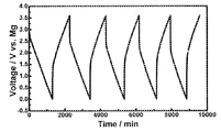
- the result of the potential-time characteristic of all the Mg batteries when using V a OPO b obtained in Example 1 as a positive electrode active material is shown.
- the charge / discharge characteristics when V a OPO b obtained in Example 1 is used as the positive electrode active material, and the relationship between each cycle and the discharge capacity are shown.
- the cycle characteristics when V a OPO b obtained in Example 1 is used as the positive electrode active material are shown.
- the XRD pattern of the product (Nb a OPO b ) baked in Example 2 is shown.
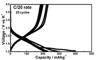
- the result (C / 20 rate) of the test example 2 when the positive electrode active material for secondary batteries containing Nb a OPO b is used as a positive electrode material is shown (C / 20 rate).
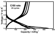
- the result (C / 50 rate) of the test example 2 when the positive electrode active material for secondary batteries containing Nb a OPO b is used as a positive electrode material is shown (C / 50 rate).
- the result (charge / discharge characteristic and relationship between each cycle and discharge capacity) of Test Example 2 when a positive electrode active material for a secondary battery containing Nb a OPO b is used as a positive electrode material is shown.
- the result of the charging / discharging curve of KVOPO 4 (KVPO 5 ) is shown.
- Positive electrode active material for secondary battery The positive electrode active material for a secondary battery of this embodiment is represented by the following general formula (1) M a OXO b (1) (In the formula (1), M is at least one selected from the group consisting of Ti, V, Nb and Mo, X is at least one selected from the group consisting of P and S, and 0 .5 ⁇ a ⁇ 1.2, 3.5 ⁇ b ⁇ 4.5) The compound represented by these is included.
- the positive electrode active material for a secondary battery of the present embodiment is a positive electrode active material for constituting a secondary battery whose carrier ions are other than lithium ions, that is, a secondary battery other than a lithium ion secondary battery.
- the positive electrode active material for secondary batteries of the present embodiment is useful as a positive electrode active material for various metal ion secondary batteries because various metal ions can be inserted and desorbed.
- the positive electrode active material for a secondary battery of the present embodiment can insert and desorb magnesium ions when a compound containing Mg is used as an electrolyte in the secondary battery. It is useful as a positive electrode active material.
- the positive electrode active material for a secondary battery of the present embodiment can insert and desorb potassium ions when a compound containing potassium (K) is used as an electrolyte in the secondary battery. It is useful as a positive electrode active material for a potassium ion secondary battery.
- M is at least one selected from the group consisting of Ti, V, Nb, and Mo.
- M is preferably V, and in this case, the positive electrode active material for the secondary battery can be produced at a lower cost, and the theoretical capacity of the positive electrode active material for the secondary battery becomes higher. It is easy to improve the potential of the secondary battery.
- X is at least one selected from the group consisting of P and S.
- Examples of the compound represented by the general formula (1) include V a OPO b (for example, VPO 5 ) and Nb a OPO b (for example, NbPO 5 ).
- the positive electrode active material for the secondary battery is advantageous in terms of excellent theoretical capacity and high potential in addition to lower costs.
- the crystal structure of the compound represented by the general formula (1) is not particularly limited.
- the crystal structure of the compound represented by the general formula (1) (particularly VOPO 4 ) can form various structures such as ⁇ phase, ⁇ phase, ⁇ phase, ⁇ phase, ⁇ phase, and ⁇ phase.
- ⁇ phase and ⁇ phase are preferable, and ⁇ phase is particularly preferable.
- Such a crystal structure is easy to manufacture, and when used as a positive electrode active material for a secondary battery, the secondary battery can have a higher capacity.
- the abundance of the crystal structure as the main phase is not particularly limited, and is preferably 80 mol% or more, more preferably 90 mol% or more based on the whole compound represented by the general formula (1).
- the compound represented by the general formula (1) can be formed as a material having a single-phase crystal structure.
- the compound represented by the general formula (1) may be formed as a material having a plurality of crystal structures. The crystal structure of the compound represented by the general formula (1) can be confirmed by X-ray diffraction measurement.
- the diffraction angle represented by 2 ⁇ is in the range of 16.67 to 17.56 °, in the range of 18.95 to 20.03 °, 21.97. 23.43 ° range, 25.04-25.83 ° range, 26.00-26.84 ° range, 27.83-28.52 ° range, 28.79-29.47 ° range Range, 27.79 to 30.58 ° range, 31.19 to 32.37 ° range, 33.53 to 35.10 ° range, 36.61 to 38.34 ° range, 38.89 to 42.14 ° range, 42.87 to 43.93 ° range, 45.04 to 51.02 ° range, 51.81 to 58.40 ° range and 59.46 to 64.04 ° range It is preferable to have a peak. In this case, when the compound represented by the general formula (1) is used for the positive electrode active material for the secondary battery, the capacity of the secondary battery is easily.
- the compound represented by the general formula (1) having the above crystal structure and composition can be, for example, in the form of a particulate powder.
- the average particle size is preferably 0.2 to 50 ⁇ m, and preferably 0.5 to 30 ⁇ m from the viewpoints of ease of insertion and removal of various metal ions, capacity, and high potential. More preferred.
- the average particle size of the compound represented by the general formula (1) is measured by observation with an electron microscope (SEM).
- SEM electron microscope
- the average particle diameter here refers to, for example, an arithmetic average value of equivalent circle diameters measured by direct observation with an electron microscope.
- the secondary battery can have a high capacity.
- M is at least one selected from the group consisting of Ti, V, Nb and Mo, a redox reaction in two stages occurs. Battery capacity tends to be high. For example, if M is V, a redox reaction in two stages of V 5+ / V 4+ and V 4+ / V 3+ occurs.
- the compound represented by the general formula (1) can be produced by an inexpensive and easy process. Therefore, according to the positive electrode active material for a secondary battery of the present embodiment, various secondary batteries can be provided at a low cost. Therefore, the positive electrode active material for a secondary battery of the present embodiment has a high energy density. It is suitable as a positive electrode material constituting a secondary battery (for example, a magnesium ion secondary battery or a potassium ion secondary battery).
- the positive electrode active material for secondary batteries of the present embodiment can also contain an unavoidable impurity other than the compound represented by General formula (1).
- the inevitable impurities include a raw material mixture described later.
- the compound represented by the general formula (1) and a carbon material may form a composite.
- the carbon material suppresses the grain growth of the compound represented by the general formula (1) at the time of firing, it can be a fine particle positive electrode active material for a secondary battery having excellent electrode characteristics.
- the content of the carbon material is preferably adjusted to 3 to 20% by mass, particularly 5 to 15% by mass in the positive electrode active material for the secondary battery.
- the method for producing the secondary battery positive electrode active material is not particularly limited.
- the compound is produced by a production method including a heating step of heating a raw material mixture containing the raw material containing M and the raw material containing X to obtain a positive electrode active material for a secondary battery. it can.
- this method will be specifically described.
- the raw material mixture in the said manufacturing method contains the raw material containing M, and the raw material containing said X.
- the raw material mixture may be a compound having both M and X, and may contain one or more of such compounds.
- the raw material mixture may include two or more raw materials containing M, or may include two or more raw materials containing X.
- the raw material containing M may be, for example, metal M (M is one selected from the group consisting of Ti, V, Nb and Mo), or may be a compound containing M. Moreover, the raw material containing M may be two or more kinds of alloys selected from the group consisting of Ti, V, Nb, and Mo, or may contain a metal M alone in addition to this alloy. Examples of the compound containing M include vanadium oxide (V 2 O 5 ), titanium oxide, niobium oxide, molybdenum oxide, and the like. Other examples of the compound containing M include metal M hydroxide, chloride, carbonate, nitrate, oxalate, and the like. The compound containing M may be a hydrate.
- the raw material containing X may be a simple substance (that is, P or S), or may be a compound containing X.
- Examples of the compound containing X include NH 4 H 2 PO 4 (ammonium dihydrogen phosphate).
- examples of the compound containing X include X oxide, hydroxide, chloride, carbonate, nitrate, and oxalate.
- the compound containing X may be a hydrate.
- the raw material mixture does not contain other metal elements other than M and X (particularly rare metal elements).
- other metal elements it is desirable that they are separated and volatilized by heat treatment in a non-oxidizing atmosphere.
- each raw material which comprises a raw material mixture all may use a commercial item, or it can also synthesize
- the shape of the raw material mixture there is no particular limitation on the shape of the raw material mixture, and powder is preferable from the viewpoint of handleability. Further, from the viewpoint of reactivity, the particles are preferably fine, and a powder having an average particle size of 1 ⁇ m or less (particularly about 60 to 80 nm) is preferable. The average particle diameter of each raw material is measured by electron microscope observation (SEM).
- the raw material mixture can be prepared by mixing a raw material containing M and a raw material containing X at a predetermined blending ratio.
- the mixing method is not particularly limited, and for example, a method that can uniformly mix the raw materials can be employed. Specifically, mortar mixing, mechanical milling treatment, coprecipitation method, a method of mixing after each raw material is dispersed in a solvent, a method of mixing each raw material at once in a solvent, etc. may be adopted. it can. Among these, when mortar mixing is adopted, the compound represented by the general formula (1) can be obtained by a simpler method. A coprecipitation method can be employed to obtain a more uniformly mixed raw material mixture.
- the mixing ratio of each raw material in each raw material mixture is not particularly limited.
- the heating step can be performed, for example, in an inert gas atmosphere such as argon or nitrogen. Alternatively, the heating step may be performed under reduced pressure such as vacuum.
- the heating temperature (that is, the firing temperature) in the heating step is preferably 500 to 1500 ° C.
- the operation of the heating step can be performed more easily, and the obtained compound can easily form a desired crystal structure.
- the crystallinity and electrode characteristics (particularly capacity and potential) of the resulting compound are likely to be improved.
- the lower limit of the heating temperature in the heating step is preferably 700 ° C, and more preferably 800 ° C.
- the upper limit of a calcination temperature can be suitably determined in the range which can operate easily in manufacture of the compound represented by General formula (1) (for example, 1500 degreeC).
- the heating time in the heating step is not particularly limited. For example, 10 minutes to 48 hours are preferable, and 30 minutes to 24 hours are more preferable.
- the desired compound After heating for a predetermined time, the desired compound is obtained by cooling.
- the cooling rate is not particularly limited.
- baking may be performed again at the heating temperature.
- the compound represented by the general formula (1) can be produced by a method such as a coprecipitation method, a sol-gel method, or a hydrothermal synthesis method in addition to the above production method.
- Secondary battery of this embodiment includes the above-described positive electrode active material for a secondary battery as a constituent element.
- the secondary battery of this embodiment shows a secondary battery other than a lithium ion secondary battery, such as a magnesium ion secondary battery or a potassium ion secondary battery.
- the basic structure of the secondary battery can be configured with reference to a known non-aqueous electrolyte secondary battery except that the positive electrode active material for a secondary battery is used as a positive electrode active material.
- the positive electrode, the negative electrode, and the separator can be disposed in the battery container so that the positive electrode and the negative electrode are separated from each other by the separator. Then, after filling the non-aqueous electrolyte into the battery container, the secondary battery can be manufactured by sealing the battery container.
- the material, size and shape of the battery container can be appropriately determined according to the use of the secondary battery.
- the positive electrode can employ a structure in which a positive electrode material containing the positive electrode active material for a secondary battery of the above embodiment is supported on a positive electrode current collector.
- a positive electrode material containing the positive electrode active material for a secondary battery of the above embodiment is supported on a positive electrode current collector.
- it can be produced by applying the positive electrode active material for a secondary battery, a conductive additive, and, if necessary, a positive electrode mixture containing a binder to a positive electrode current collector.
- conductive aid for example, carbon materials such as acetylene black, ketjen black, carbon nanotube, vapor grown carbon fiber, carbon nanofiber, graphite, and coke can be used.
- carbon materials such as acetylene black, ketjen black, carbon nanotube, vapor grown carbon fiber, carbon nanofiber, graphite, and coke
- a powder form etc. are employable.
- binder examples include, but are not limited to, fluorine resins such as polyvinylidene fluoride resin and polytetrafluoroethylene.
- the content of various components in the positive electrode material is not particularly limited and can be appropriately determined according to the type of the material.
- the positive electrode active material for a secondary battery is 50 to 95% by volume (particularly 70 to 90%). Volume%), 2.5 to 25 volume% (especially 5 to 15 volume%) of a conductive assistant, and 2.5 to 25 volume% (especially 5 to 15 volume%) of a binder.
- Examples of the material constituting the positive electrode current collector include aluminum, titanium, platinum, molybdenum, stainless steel, and copper.
- Examples of the shape of the positive electrode current collector include a porous body, a foil, a plate, and a mesh made of fibers.
- the amount of the positive electrode material applied to the positive electrode current collector is preferably determined as appropriate according to the desired use of the secondary battery.
- Examples of the negative electrode active material constituting the negative electrode of the magnesium ion secondary battery include magnesium metal; silicon; silicon-containing acrylate compound; magnesium alloy; M 1 M 2 2 O 4 (M 1 : Co, Ni, Mn, Sn, etc. , M 2 : Mn, Fe, Zn, etc.) or a ternary or quaternary oxide; M 3 3 O 4 (M 3 : Fe, Co, Ni, Mn, etc.), M 4 2 O 3 (M 4 : Fe, Co, Ni, Mn, etc.), MnV 2 O 6 , M 5 O 2 (M 5 : Sn, Ti etc.), M 6 O (M 6 : Fe, Co, Ni, Mn, Sn, Cu etc.) Metal oxides represented by, etc .; graphite, hard carbon, soft carbon, graphene; the above-mentioned carbon materials; organic compounds such as MgC 8 H 4 O 4 , MgC 8 H 4 O 4 .2H 2 O, etc.
- magnesium alloys include alloys containing magnesium and aluminum as constituent elements, alloys containing magnesium and zinc as constituent elements, alloys containing magnesium and manganese as constituent elements, alloys containing magnesium and bismuth as constituent elements, magnesium and nickel Alloy containing magnesium, alloy containing magnesium and antimony as constituent elements, alloy containing magnesium and tin as constituent elements, alloy containing magnesium and indium as constituent elements; metal (scandium, titanium, vanadium, chromium, zirconium, niobium) , molybdenum, hafnium, MXene based alloy containing as constituent elements carbon and tantalum), M 7 x BC 3 alloy (M 7: Sc, Ti, V, Cr, Zr, Nb, Mo, Hf, T Quaternary layered carbide or nitride compound etc.) and the like; alloys containing magnesium and lead as a constituent element thereof.
- Such a negative electrode may be an electrode in which metal magnesium, graphite or magnesium alloy is supported on a current collector, and metal magnesium, graphite, carbon or magnesium alloy is formed into a shape suitable for the electrode (for example, a plate shape).
- the electrode obtained in this way may be used.
- examples of the negative electrode active material constituting the negative electrode of the potassium ion secondary battery include potassium metal; silicon; silicon-containing acrylate compound; potassium alloy; M 1 M 2 2 O 4 (M 1 : Co, Ni, Mn, Ternary or quaternary oxides represented by Sn, etc., M 2 : Mn, Fe, Zn, etc .; M 3 3 O 4 (M 3 : Fe, Co, Ni, Mn, etc.), M 4 2 O 3 ( M 4: Fe, Co, Ni , Mn , etc.), MnV 2 O 6, M 5 O 2 (M 5: Sn, Ti , etc.), M 6 O (M 6 : Fe, Co, Ni, Mn, Sn, Cu Etc.) Metal oxides represented by, etc .; graphite, hard carbon, soft carbon, graphene; the above-mentioned carbon materials; Lepidocrosite type K 0.8 Li 0.2 Ti 1.67 O 4 ; KC 8 ; KTi 3 O 4 ; K 2 Ti
- potassium alloys include alloys containing potassium and aluminum as constituent elements, alloys containing potassium and zinc as constituent elements, alloys containing potassium and manganese as constituent elements, alloys containing potassium and bismuth as constituent elements, potassium and nickel Alloy containing potassium and antimony as constituent elements, alloy containing potassium and tin as constituent elements, alloy containing potassium and indium as constituent elements; metal (scandium, titanium, vanadium, chromium, zirconium, niobium) , Molybdenum, hafnium, tantalum, etc.) and carbon as a component element, MXene alloy, M 7 x BC 3 alloy (M 7 : Sc, Ti, V, Cr, Zr, Nb, Mo, Hf, Ta, etc.), etc.
- the negative electrode may be an electrode in which metallic potassium, graphite, or a potassium alloy is supported on a current collector, and metallic potassium, graphite, carbon, or a potassium alloy is formed into a shape (for example, a plate shape) suitable for the electrode.
- the electrode obtained in this way may be used.
- the negative electrode can be composed of a negative electrode active material, and adopts a configuration in which a negative electrode material containing a negative electrode active material, a conductive additive, and a binder as necessary is supported on the negative electrode current collector. You can also. When adopting a configuration in which the negative electrode material is supported on the negative electrode current collector, a negative electrode mixture containing a negative electrode active material, a conductive additive, and a binder as necessary is applied to the negative electrode current collector. Can be manufactured.
- the negative electrode When the negative electrode is composed of a negative electrode active material, it can be obtained by molding the negative electrode active material into a shape (such as a plate shape) suitable for the electrode.
- the types of the conductive auxiliary agent and the binder, and the negative electrode active material, the conductive auxiliary agent, and the binder content are those of the positive electrode described above. Can be applied.
- the material constituting the negative electrode current collector include aluminum, copper, nickel, and stainless steel.
- Examples of the shape of the negative electrode current collector include a porous body, a foil, a plate, and a mesh made of fibers. In addition, it is preferable to determine suitably the application quantity of the negative electrode material with respect to a negative electrode collector according to the use etc. of a secondary battery.
- the separator is not limited as long as it is made of a material that can separate the positive electrode and the negative electrode in the battery and can hold the electrolytic solution to ensure the ionic conductivity between the positive electrode and the negative electrode.
- polyolefin resin such as polyethylene and polypropylene; polyimide; polyvinyl alcohol; fluorine resin such as terminal aminated polyethylene oxide polytetrafluoroethylene; acrylic resin; nylon; aromatic aramid; inorganic glass; Materials in the form of membranes, nonwoven fabrics, woven fabrics, etc. can be used.
- the non-aqueous electrolyte can be appropriately selected according to the type of secondary battery.
- an electrolytic solution containing magnesium ions is preferable.
- examples of such an electrolytic solution include a magnesium salt solution, an ionic liquid composed of an inorganic material containing magnesium, and the like.
- Examples of such an electrolytic solution include a solution in which a magnesium salt is dissolved in a solvent, an ionic liquid composed of an inorganic material containing magnesium, and the like, but is not limited to such an example.
- magnesium salt examples include magnesium halides such as magnesium chloride, magnesium bromide and magnesium iodide, magnesium inorganic salts such as magnesium perchlorate, magnesium tetrafluoroborate, magnesium hexafluorophosphate and magnesium hexafluoroarsenate.
- magnesium halides such as magnesium chloride, magnesium bromide and magnesium iodide
- magnesium inorganic salts such as magnesium perchlorate, magnesium tetrafluoroborate, magnesium hexafluorophosphate and magnesium hexafluoroarsenate.
- Compound Magnesium organic salt compounds such as bis (trifluoromethylsulfonyl) imide magnesium, magnesium benzoate, magnesium salicylate, magnesium phthalate, magnesium acetate, magnesium propionate, tris (pentafluoroethane) trifluorophosphate magnesium, Grignard reagent, etc.
- the present invention is not limited to such examples.
- a solid electrolyte can be used instead of the non-aqueous electrolyte.
- the electrolytic solution may be an electrolytic solution containing potassium cations.
- the electrolytic solution include a solution in which a potassium salt is dissolved in a solvent, an ionic liquid composed of an inorganic material containing potassium, and the like, but is not limited to such an example.
- potassium salts include potassium halides such as potassium chloride, potassium bromide, potassium fluoride, potassium iodide, potassium perchlorate, potassium tetrafluoroborate, potassium hexafluorophosphate, potassium hexafluoroarsenate, etc.
- Potassium inorganic salt compounds potassium trifluoromethanesulfonate, potassium nonafluorobutanesulfonate, potassium bis (trifluoromethanesulfonyl) imide, potassium bis (nonafluorobutanesulfonyl) imide, potassium bis (fluorosulfonyl) imide, potassium trifluoroacetate , Potassium pentafluoropropionate, potassium ethoxide, potassium tetraphenylborate, potassium tetrafluoroborate, potassium hexafluorophosphate, bis (trifluoromethyls Phosphonyl) imide potassium, potassium bis (pentafluoroethanesulfonyl) imide potassium, potassium tris (pentafluoroethane) trifluorophosphate, potassium benzoate, potassium salicylate, potassium phthalate, potassium acetate, potassium propionate, Grignard reagents, etc.
- a solid electrolyte can be used instead of the non-aqueous electrolyte.
- the solid electrolyte for a potassium secondary battery include KBiO 3 , KNO 2 —Gd 2 O 3 solid solution system, KSbO 3 , K 2 SO 4 , KH 2 PO 4 , KZr 2 (PO 4 ) 3 , K 9 Fe ( Listed are potassium ion conductors such as MoO 4 ) 6 , K 4 Fe 3 (PO 4 ) 2 P 27 , K 3 MnTi (PO 4 ) 3, and the like.
- the solvent examples include carbonate compounds such as propylene carbonate, ethylene carbonate, dimethol carbonate, ethylmethyl carbonate, and diethyl carbonate; lactone compounds such as ⁇ -butyrolactone and ⁇ -valerolactone; tetrahydrofuran, 2-methyltetrahydrofuran, diethyl ether, Such as diisopropyl ether, dibutyl ether, methoxymethane, N, N-dimethylformamide, glyme, N-propyl-N-methylpyrrolidinium bis (trifluoromethanesulfonyl) imide, dimethoxyethane, dimethoxymethane, diethoxymethane, dietochiethane, propylene glycol dimethyl ether Ether compounds; acetonitrile and the like.
- carbonate compounds such as propylene carbonate, ethylene carbonate, dimethol carbonate, ethylmethyl carbonate, and diethyl
- the secondary battery of the present embodiment uses a compound having the composition represented by the formula (1), a higher potential and energy density can be secured during the oxidation-reduction reaction (charge / discharge reaction), Moreover, it is excellent in safety (polyanion skeleton) and practicality. Therefore, the secondary battery of this embodiment can be suitably used for, for example, a device that is required to be downsized and high performance.
- magnesium ion secondary battery means a secondary battery using magnesium ions as carrier ions
- magnesium secondary battery uses magnesium metal or a magnesium alloy as a negative electrode active material. It means a secondary battery.
- potassium ion secondary battery means a secondary battery using potassium ions as carrier ions
- potassium secondary battery means a secondary battery using potassium metal or a potassium alloy as a negative electrode active material.
- Example 1 NH 4 H 2 PO 4 and V 2 O 5 are prepared as raw powders, and NH 4 H 2 PO 4 and V 2 O 5 are weighed so that the molar ratio of vanadium and phosphorus is 1: 2,
- the raw material mixture was obtained by mixing for about 30 minutes in a mortar. Thereafter, the raw material mixture was placed in a chrome steel container together with zirconia balls (15 mm ⁇ ⁇ 10), added with acetone, and pulverized and mixed at 400 rpm for 6 hours in a planetary ball mill (Fritsch; P-6). Then, after distilling acetone off under reduced pressure, the recovered powder was pelleted at 40 MPa and fired at 700 ° C. for 2 hours in argon.
- the temperature raising rate was set to 400 ° C./h.
- the cooling rate was set to 100 ° C./h up to 300 ° C., and thereafter it was allowed to cool to room temperature by natural cooling. Then, V a OPO b was obtained by firing again at 700 ° C. for 3 hours.
- Example 2 Prepare NH 4 H 2 PO 4 and Nb 2 O 5 as raw powders, weigh NH 4 H 2 PO 4 and Nb 2 O 5 so that the molar ratio of niobium and phosphorus is 1: 2, and use an agate mortar.
- the raw material mixture was obtained by mixing for about 30 minutes. Thereafter, the raw material mixture was placed in a chrome steel container together with zirconia balls (15 mm ⁇ ⁇ 10), added with acetone, and pulverized and mixed at 400 rpm for 6 hours in a planetary ball mill (Fritsch; P-6).
- the recovered powder was pellet-molded at 40 MPa, and calcined at a calcining temperature of 900 ° C. for 8 hours or more in argon.
- the temperature raising rate was set to 400 ° C./h.
- the cooling rate was set to 100 ° C./h up to 300 ° C., and thereafter, Nb a OPO b was obtained by cooling to room temperature by natural cooling.
- ⁇ Evaluation method> [Powder X-ray diffraction (XRD) measurement]
- the synthesized sample was measured using an X-ray diffractometer (RINT-UltimaIII / G manufactured by Rigaku Corporation).
- a CuK ⁇ ray was used as the X-ray source, the applied voltage was 40 kV, and the current value was 40 mA.
- the measurement was performed at an angle range of 10 ° to 80 ° at a scanning speed of 0.02 ° / sec.
- ICP-AES measurement ICP-AES measurement was performed using an inductively coupled plasma emission spectrometer (“iCAP6500” manufactured by Thermo Fisher Scientific).
- the cell used was a CR2032-type coin cell.
- the electrolyte solution was prepared by dissolving Mg (TFSI) 2 in an ethylene glycol dimethyl ether dimethoxyethylene glycol (trade name: monoglyme) so that its concentration would be 0.5 M, using the Mg disk as the negative electrode.
- the constant current charge / discharge measurement was performed by using a voltage switch, setting the current to 5 mAg ⁇ 1 , the upper limit voltage 3.6 V, and the lower limit voltage 0 V, and starting from charge. The measurement was performed at room temperature.
- Test Example 2 Examination of cation desorption and insertion (potassium secondary battery)
- the cell used was a CR2032-type coin cell. Natural graphite was used as the negative electrode, and 1 M KTFSI (PC solvent) was used as the electrolyte.
- the constant current charge / discharge measurement was started by charging using a voltage switch, setting current 10 mAg ⁇ 1 , upper limit voltage 4.2 V, and lower limit voltage 1.5 V. Charge / discharge measurement was performed in a state where the cell was placed in a 55 ° C. constant temperature bath.
- FIG. 1A shows an XRD pattern of the product (V a OPO b ) baked in Example 1.
- the X-ray wavelength used is 1.5418 mm.
- V a OPO b exhibit polymorphism, among them, ⁇ -V a OPO b polymorph is the most stable phase. This polymorphic V a OPO b was evaluated as a positive electrode material for magnesium and potassium secondary batteries (Test Example 1 and Test Example 2).
- the obtained V a OPO b crystal has a diffraction angle represented by 2 ⁇ in the range of 16.67 to 17.56 °, the range of 18.95 to 20.03 °, 21.97. 23.43 ° range, 25.04-25.83 ° range, 26.00-26.84 ° range, 27.83-28.52 ° range, 28.79-29.47 ° range Range, 27.79 to 30.58 ° range, 31.19 to 32.37 ° range, 33.53 to 35.10 ° range, 36.61 to 38.34 ° range, 38.89 to 42.14 ° range, 42.87 to 43.93 ° range, 45.04 to 51.02 ° range, 51.81 to 58.40 ° range and 59.46 to 64.04 ° range
- the peak position of V a OPO b is almost close to ⁇ -VPO 5 all right. From this result, it can be seen that the lattice constant of V a OPO b is almost close to
- FIG. 1B shows an XRD pattern refined by the Rietveld method.
- FIG. 2 shows an SEM image of V a OPO b obtained in Example 1.
- the scale bar indicates 23.2 ⁇ m. From this result, it can be seen that V a OPO b obtained in Example 1 has an average particle diameter of about 30 ⁇ m, although the particles tend to aggregate.
- FIG. 3 shows the results of Test Example 1 (results of potential-time characteristics of all Mg batteries) when the positive electrode active material for secondary batteries containing V a OPO b obtained in Example 1 was used as the positive electrode material. Show. As a result, it was found that a potential response suggesting insertion and detachment of magnesium was observed.
- FIG. 4 shows the results of Test Example 2 (charge / discharge characteristics and the relationship between each cycle and the discharge capacity) when a positive electrode active material for a secondary battery containing V a OPO b was used as the positive electrode material. . From this result, it can be seen that good cycle characteristics are exhibited by taking in and out potassium ions. It was also found that about 70% of the initial capacity was maintained at the 50th cycle. Furthermore, as shown in FIG. 5, it can be seen that a good reversible capacity was obtained in the cycle test, and the capacity maintenance after 50 cycles showed a stable characteristic of 70%.
- the lead-out capacity (charge capacity) is 70 mAhg ⁇ 1 and the average voltage is about 3.75 V. It can be seen that the obtained positive electrode material is expected as a high capacity / high potential material.
- V a case where OPO b the positive electrode active material for a secondary battery comprising the positive electrode material V in V a OPO b containing a strong polyanion units (PO 4 3-) bunk redox-electron reaction (V 5 + / V 4+ and V 4+ / V 3+ pairs).
- FIG. 6 shows the XRD pattern of the product (Nb a OPO b ) calcined in Example 2.
- the X-ray wavelength used is 1.5418 mm.
- FIGS. 7 and 8 show the results of Test Example 2 (charge / discharge characteristics and the relationship between each cycle and the discharge capacity) when a positive electrode active material for a secondary battery containing Nb a OPO b is used as the positive electrode material.
- FIG. 7 is C / 20 rate
- FIG. 8 is C / 50 rate, both are 25 cycles). From this result, it can be seen from this result that both C / 20 rate and C / 50 rate show good cycle characteristics by taking in and out potassium ions. It was also found that about 70% of the initial capacity was maintained at the 50th cycle. Further, as shown in FIGS. 7 and 8, it can be seen that a good reversible capacity was obtained in the cycle test, and the capacity maintenance after 25 cycles showed a stable characteristic of about 70%.
- FIG. 9 shows a summary of the results of Test Example 2 (charge / discharge characteristics and the relationship between each cycle and the discharge capacity) when a positive electrode active material for a secondary battery containing Nb a OPO b was used as the positive electrode material. ing. As shown in FIG. 9, a good reversible capacity was obtained in the cycle test (relation between each cycle and the discharge capacity), and a relatively high capacity of about 100 mAhg ⁇ 1 was obtained at a rate of C / 5. Although the mix electrode has not been optimized, it can be said that NbOPO 4 exhibits good rate characteristics.
- K 2 CO 3 , V a OPO b and carbon are prepared as raw powders, weighed so that the molar ratio of K, V and C is 2: 4: 1, and mixed in an agate mortar for about 30 minutes. A mixture was obtained. Then, the raw material mixture was pellet-molded at 40 MPa and fired in argon at a firing temperature of 700 ° C. for 1 hour or longer. At this time, the temperature raising rate was set to 400 ° C./h. The cooling rate was set to 100 ° C./h up to 300 ° C., and then KV a OPO b was obtained by allowing to cool to room temperature by natural cooling.
- FIG. 10 shows the result of the charge / discharge curve of KV a OPO b . From this result, it can be seen that although the operating potential is high (around 4 V), the capacity that can be extracted is small, and it is effective to use a V a OPO b skeleton that does not contain potassium in order to improve the performance of the secondary battery. I understand.
Landscapes
- Chemical & Material Sciences (AREA)
- Inorganic Chemistry (AREA)
- Organic Chemistry (AREA)
- Engineering & Computer Science (AREA)
- Chemical Kinetics & Catalysis (AREA)
- Electrochemistry (AREA)
- General Chemical & Material Sciences (AREA)
- Materials Engineering (AREA)
- Manufacturing & Machinery (AREA)
- Secondary Cells (AREA)
- Battery Electrode And Active Subsutance (AREA)
Abstract
種々の二次電池に対して充放電可能で、これらの二次電池の特性向上を図ることができる二次電池用正極活物質及びその製造方法、並びに該正極活物質を構成要素とする二次電池を提供する。 本発明に係るキャリアイオンがリチウムイオン以外である二次電池用正極活物質は、一般式(1) MaOXOb (1) (ここで、式(1)中、Mは、Ti、V、Nb及びMoからなる群より選ばれる少なくとも1種であり、XはP及びSからなる群より選ばれる少なくとも1種であり、0.5≦a≦1.2、3.5≦b≦4.5である)で表される化合物を含む。
Description
本発明は、二次電池用正極活物質及びその製造方法、並びに、二次電池に関する。
エネルギー問題の解決に向け、エネルギー貯蔵媒体は必要不可欠なものであり、高性能な二次電池の開発が急務である。現在、最高性能を誇る二次電池はリチウムイオン二次電池であるが、今後の利用展開として考えられる電気自動車やスマートグリッドの実現にはその容量面、コスト面、安全面に課題が残る。更なる発展に向けては現状の系を超越した革新的な二次電池の開発が必要であり、その方向性の一つに多価のイオンをキャリアとする多価イオン二次電池がある。例えば、マグネシウムを負極とする二次電池系は、高い理論容量密度を有し、資源が豊富で、高融点で安全性に富む点から注目されている。
マグネシウムは高い理論重量、体積容量を有し、比較的卑な酸化還元電位を示すため、マグネシウムを負極に用いた二次電池は高エネルギー密度を有することが予想される。特に体積当たりの理論容量に関してはリチウムを凌ぐ値であり、これは電気自動車用二次電池等、限られたスペース(体積)に大容量を詰め込める点で有利である。さらに、マグネシウム埋蔵量が地殻層に豊富であり、リチウムイオン二次電池の欠点である、資源枯渇及びコストの問題がクリアできる。また、マグネシウムは融点が約650℃であり、Li(180℃)、Na(98℃)などと比べて非常に高い。融点は金属の安定性の指標であり、マグネシウムを用いた二次電池は安全性の向上も見込める。将来金属負極の実用化まで見据えると負極金属の安全性というのは非常に重要なファクターになる。さらに、リチウム、ナトリウムなどは空気中の水分などと激しく反応するため取り扱いが困難であるが、マグネシウムは空気中で安定であり、取り扱いも容易である。これらの理由から、マグネシウム二次電池はポストリチウムイオン二次電池の候補とみなされ、近年、多数の研究が行われている。
マグネシウム二次電池系の創製にはまだいくつかの課題が存在する。特に、正極材料においては、多価のイオンはリチウムイオンに比べ、固相内でのアニオンとのクーロン相互作用は二倍と大きくなり、また、イオン半径がリチウムイオンより小さいため、アニオンとの距離が小さくなり、さらにその相互作用は増大する。それにより、多価のイオンは正極ホスト化合物内での静電相互作用の影響が非常に大きくなることが予想されるため、より価数の高いイオンほどトポケミカル反応に基づくインターカレーション電極の適応は困難である。
これに対し、近年ではマグネシウム二次電池向けの正極材料は多々報告されており、正極としてシェブレル相を有するMo6T8(T=S,Se)、V2O5、TiS2ナノチューブ graphene-like MoS2などのナノ構造材料はマグネシウム二次電池として安定で可逆的な充放電特性を示すことが報告されている(例えば、非特許文献1等を参照)。
Prototype systems for rechargeable magnesium batteries、Nature 407、724-727(2000)
しかしながら、上記多価イオン二次電池を実現するために克服するべき課題は多く、特に、重要なのが正極材料の開発である。多価イオンはリチウムイオンに比べ、固相内でのアニオンとのクーロン相互作用が飛躍的に増大するため、正極ホスト化合物中での多価イオンの固相内拡散が遅く、反応が大きく制限される要因となり得る。上記非特許文献1に開示されるような硫黄イオン等の塩基を含む化合物においても、反応電位が低下しやすく(約1.1V)、また、シェブレル相は分子量が大きくその理論容量が低い(約116mAhg-1)という問題点もあった。このような観点から、正極内における固相内の拡散の問題を解決でき、かつ、その二次電池のポテンシャルを引き出すべく負極と同様で資源が豊富な元素からなり高容量な正極材料の開発が求められていた。
本発明は、上記に鑑みてなされたものであり、種々の二次電池に対して充放電可能で、これらの二次電池の特性向上を図ることができる二次電池用正極活物質及びその製造方法、並びに該正極活物質を構成要素とする二次電池を提供することを目的とする。
本発明者は、上記目的を達成すべく鋭意研究を重ねた結果、特定組成の化合物を使用することにより、上記目的を達成できることを見出し、本発明を完成するに至った。
すなわち、本発明は、例えば、以下の項に記載の主題を包含する。
項1. 下記一般式(1)
MaOXOb (1)
(ここで、式(1)中、Mは、Ti、V、Nb及びMoからなる群より選ばれる少なくとも1種であり、XはP及びSからなる群より選ばれる少なくとも1種であり、0.5≦a≦1.2、3.5≦b≦4.5である)
で表される化合物を含み、
キャリアイオンがリチウムイオン以外である二次電池用正極活物質。
項2.上記項1に記載の正極活物質を構成要素とする二次電池。
項3.上記項1に記載の二次電池用正極活物質の製造方法であって、
上記Mを含有する原料と、上記Xを含有する原料とを含む原料混合物を加熱する加熱工程を備える、製造方法。
項4.前記加熱工程における加熱温度が500~1500℃である、上記項3に記載の製造方法。
項1. 下記一般式(1)
MaOXOb (1)
(ここで、式(1)中、Mは、Ti、V、Nb及びMoからなる群より選ばれる少なくとも1種であり、XはP及びSからなる群より選ばれる少なくとも1種であり、0.5≦a≦1.2、3.5≦b≦4.5である)
で表される化合物を含み、
キャリアイオンがリチウムイオン以外である二次電池用正極活物質。
項2.上記項1に記載の正極活物質を構成要素とする二次電池。
項3.上記項1に記載の二次電池用正極活物質の製造方法であって、
上記Mを含有する原料と、上記Xを含有する原料とを含む原料混合物を加熱する加熱工程を備える、製造方法。
項4.前記加熱工程における加熱温度が500~1500℃である、上記項3に記載の製造方法。
本発明に係る二次電池用正極活物質は、マグネシウムイオン二次電池やカリウムイオン電池等の種々の二次電池に対して充放電可能で、二次電池のエネルギー密度及び容量を高めることが可能であり、低コストでポストリチウム二次電池を構築できる。
以下、本発明の実施形態について詳細に説明する。
1.二次電池用正極活物質
本実施形態の二次電池用正極活物質は、下記一般式(1)
MaOXOb (1)
(ここで、式(1)中、Mは、Ti、V、Nb及びMoからなる群より選ばれる少なくとも1種であり、XはP及びSからなる群より選ばれる少なくとも1種であり、0.5≦a≦1.2、3.5≦b≦4.5である)
で表される化合物を含む。本実施形態の二次電池用正極活物質は、キャリアイオンがリチウムイオン以外である二次電池、つまり、リチウムイオン二次電池以外の二次電池を構成するための正極活物質である。
本実施形態の二次電池用正極活物質は、下記一般式(1)
MaOXOb (1)
(ここで、式(1)中、Mは、Ti、V、Nb及びMoからなる群より選ばれる少なくとも1種であり、XはP及びSからなる群より選ばれる少なくとも1種であり、0.5≦a≦1.2、3.5≦b≦4.5である)
で表される化合物を含む。本実施形態の二次電池用正極活物質は、キャリアイオンがリチウムイオン以外である二次電池、つまり、リチウムイオン二次電池以外の二次電池を構成するための正極活物質である。
本実施形態の二次電池用正極活物質は、種々の金属イオンを挿入及び脱離することができることから、各種金属イオン二次電池用正極活物質として有用である。例えば、本実施形態の二次電池用正極活物質は、二次電池において電解液としてMgを含む化合物を使用した場合にはマグネシウムイオンを挿入及び脱離することができることから、マグネシウムイオン二次電池用正極活物質として有用である。また、例えば、本実施形態の二次電池用正極活物質は、二次電池において電解液としてカリウム(K)を含む化合物を使用した場合にはカリウムイオンを挿入及び脱離することができることから、カリウムイオン二次電池用正極活物質として有用である。
一般式(1)において、Mは、Ti、V、Nb及びMoからなる群より選ばれる少なくとも1種である。中でもMは、Vであることが好ましく、この場合、二次電池用正極活物質をより低コストで製造することができ、また、二次電池用正極活物質の理論容量がより高くなるので、二次電池の電位を向上させやすい。
一般式(1)において、XはP及びSからなる群より選ばれる少なくとも1種である。これにより、二次電池用正極活物質を低コストで製造でき、また、二次電池の電位を向上させやすい。
一般式(1)で表される化合物としては、VaOPOb(例えば、VPO5)、NbaOPOb(例えば、NbPO5)が例示される。この場合、二次電池用正極活物質は、より低コストとなることに加えて、優れた理論容量、並びに高電位の観点においても有利である。
一般式(1)で表される化合物の結晶構造は特に制限されない。例えば、一般式(1)で表される化合物(特に、VOPO4)の結晶構造は、α相、β相、γ相、δ相、ε相、ω相等の種々の構造を形成することができ、中でも、α相及びβ相が好ましく、β相が特に好ましい。このような結晶構造であれば、製造が容易であり、また、二次電池用正極活物質に使用した場合に、二次電池をより高容量とすることが可能となる。
上記化合物において、主相である結晶構造の存在量は特に限定的ではなく、一般式(1)で表される化合物全体を基準として80モル%以上が好ましく、90モル%以上がより好ましい。このため、一般式(1)で表される化合物は、単相の結晶構造からなる材料として形成され得る。ただし、本発明の効果を損なわない範囲であれば、一般式(1)で表される化合物は、複数の結晶構造を有する材料して形成されていてもよい。なお、一般式(1)で表される化合物の結晶構造は、X線回折測定により確認することができる。
一般式(1)で表される化合物のX線回折測定において、2θで表される回折角度が16.67~17.56°の範囲、18.95~20.03°の範囲、21.97~23.43°の範囲、25.04~25.83°の範囲、26.00~26.84°の範囲、27.83~28.52°の範囲、28.79~29.47°の範囲、27.79~30.58°の範囲、31.19~32.37°の範囲、33.53~35.10°の範囲、36.61~38.34°の範囲、38.89~42.14°の範囲、42.87~43.93°の範囲、45.04~51.02°の範囲、51.81~58.40°の範囲および59.46~64.04°の範囲にピークを有していることが好ましい。この場合、一般式(1)で表される化合物を二次電池用正極活物質に使用した場合に、二次電池の容量を向上させやすい。
上記のような結晶構造及び組成を有する一般式(1)で表される化合物は、例えば、粒子状の粉末の形態となり得る。化合物が粒子状である場合、その平均粒子径は、各種金属イオンの挿入及び脱離のしやすさ、容量、並びに高電位の観点から、0.2~50μmが好ましく、0.5~30μmがより好ましい。一般式(1)で表される化合物の平均粒子径は、電子顕微鏡(SEM)観察により測定する。ここでいう平均粒子径とは、例えば、電子顕微鏡による直接観察によって測定された円相当径の算術平均値をいう。
本実施形態の二次電池用正極活物質を用いて、マグネシウムイオン二次電池やカリウムイオン二次電池等の二次電池を形成すると、二次電池を高容量とすることができる。しかも、一般式(1)で表わされる化合物において、MがTi、V、Nb及びMoからなる群より選ばれる少なくとも1種であることによって、二段階でのレドックス反応が起こるので、これによって二次電池の容量が高くなりやすい。例えば、MがVであれば、V5+/V4+及びV4+/V3+の二段階でのレドックス反応が起こる。
また、上記一般式(1)で表わされる化合物は、安価で容易なプロセスで製造することができる。そのため、本実施形態の二次電池用正極活物質によれば、低コストで種々の二次電池を提供することができるので、本実施形態の二次電池用正極活物質は、エネルギー密度の高い二次電池(例えば、マグネシウムイオン二次電池やカリウムイオン二次電池)を構成する正極材料として適している。
なお、本実施形態の二次電池用正極活物質の性能が阻害されない程度であれば、二次電池用正極活物質には他の材料が含まれていてもよい。また、上記二次電池用正極活物質は、一般式(1)で表わされる化合物の他に不可避不純物を含むこともできる。このような不可避不純物としては、後述の原料混合物等が挙げられ、例えば、二次電池用正極活物質中に10モル%以下程度、好ましくは5モル%以下程度、より好ましくは2モル%以下程度含有し得る。
二次電池用正極活物質においては、上記一般式(1)で表わされる化合物と炭素材料(例えば、アセチレンブラック等のカーボンブラック等)とが複合体を形成していてもよい。これにより、焼成時に炭素材料が一般式(1)で表される化合物の粒成長を抑制するため、電極特性に秀でた微粒子状の二次電池用正極活物質となり得る。この場合、炭素材料の含有量は、二次電池用正極活物質中に3~20質量%、特に5~15質量%となるように調整することが好ましい。
2.二次電池用正極活物質の製造方法
二次電池用正極活物質を製造する方法は特に限定されない。例えば、上記Mを含有する原料と、上記Xを含有する原料とを含む原料混合物を加熱する加熱工程を備える、製造方法によって、上記化合物を製造して二次電池用正極活物質を得ることができる。以下、この方法について具体的に説明する。
二次電池用正極活物質を製造する方法は特に限定されない。例えば、上記Mを含有する原料と、上記Xを含有する原料とを含む原料混合物を加熱する加熱工程を備える、製造方法によって、上記化合物を製造して二次電池用正極活物質を得ることができる。以下、この方法について具体的に説明する。
(1)原料混合物
上記製造方法における原料混合物は、Mを含有する原料と、上記Xを含有する原料とを含む。原料混合物は、MとXの両方を有する化合物であってもよく、このような化合物を1種又は2種以上含んでもよい。また、原料混合物は、Mを含有する原料を2種以上含んでもよいし、Xを含有する原料を2種以上含んでもよい。
上記製造方法における原料混合物は、Mを含有する原料と、上記Xを含有する原料とを含む。原料混合物は、MとXの両方を有する化合物であってもよく、このような化合物を1種又は2種以上含んでもよい。また、原料混合物は、Mを含有する原料を2種以上含んでもよいし、Xを含有する原料を2種以上含んでもよい。
Mを含有する原料は、例えば、金属M(MはTi,V,Nb及びMoからなる群より選ばれる1種)であってもよいし、あるいは、Mを含む化合物であってもよい。また、Mを含有する原料は、Ti,V,Nb及びMoからなる群より選ばれる2種以上の合金であってもよいし、この合金に加えて金属M単体を含んでいてもよい。Mを含む化合物としては、例えば、酸化バナジウム(V2O5)、酸化チタン、酸化ニオブ、酸化モリブデン等が例示される。その他、Mを含む化合物としては、金属Mの水酸化物、塩化物、炭酸塩、硝酸塩、シュウ酸塩等が例示される。Mを含む化合物は、水和物であってもよい。
Xを含有する原料は、単体であってもよいし(すなわち、P又はS)、あるいは、Xを含む化合物であってもよい。Xを含む化合物としては、例えば、NH4H2PO4(りん酸二水素アンモニウム)等が例示される。その他、Xを含む化合物としては、Xの酸化物、水酸化物、塩化物、炭酸塩、硝酸塩、シュウ酸塩等が例示される。Xを含む化合物は、水和物であってもよい。
原料混合物は、M及びX以外のその他金属元素(特に希少金属元素)を含まないことが好ましい。また、その他金属元素を含む場合は、非酸化性雰囲気下での熱処理により離脱して揮発していくものが望ましい。
なお、原料混合物を構成する各原料はいずれも市販品を使用してもよく、あるいは、別途合成して使用することもできる。
原料混合物の形状については特に限定はなく、取り扱い性の観点から、粉末状が好ましい。また反応性の観点から粒子は微細である方がよく平均粒子径が1μm以下(特に60~80nm程度)の粉末状が好ましい。各原料の平均粒子径は、電子顕微鏡観察(SEM)により測定する。
原料混合物は、Mを含有する原料と、Xを含有する原料とを所定の配合割合で混合することで調製することができる。混合方法は、特に制限されず、例えば、各原料を均一に混合できる方法を採用することができる。具体的には、乳鉢混合、メカニカルミリング処理、共沈法、各原料を溶媒中に分散させた後に混合する方法、各原料を溶媒中で一度に分散させて混合する方法等を採用することができる。これらのなかでも、乳鉢混合を採用するとより簡便な方法で、一般式(1)で表わされる化合物を得ることができる。より均一な混ざり合った原料混合物を得る場合は、共沈法を採用することができる。
各原料混合物における各原料の混合割合については、特に限定的ではない。例えば、最終生成物である所望の組成を有する一般式(1)で表わされる化合物が得られるように各原料を配合することが好ましい。具体的には、各原料に含まれる各元素の比率が、目的とする化合物中の各元素の比率と同一となるように各原料の配合割合を調整することが好ましい。
(2)加熱工程
加熱工程では、Mを含有する原料と、Xを含有する原料とを含む原料混合物を加熱する。
加熱工程では、Mを含有する原料と、Xを含有する原料とを含む原料混合物を加熱する。
上記加熱工程は、例えば、アルゴン、窒素等の不活性ガス雰囲気等で行うことができる。あるいは、上記加熱工程は、真空等の減圧下で行ってもよい。
加熱工程における加熱温度(すなわち、焼成温度)は500~1500℃であることが好ましい。この場合、加熱工程の操作をより容易に行うことができるとともに、得られる化合物が所望の結晶構造を形成しやすい。その結果、得られる化合物の結晶性及び電極特性(特に容量及び電位)が向上しやすい。
加熱工程における加熱温度の下限は、700℃であることが好ましく、800℃であることがより好ましい。なお、焼成温度の上限値は、一般式(1)で表わされる化合物の製造における操作を容易におこなうことができる範囲で適宜決定することができる(例えば、1500℃)。
加熱工程における加熱時間については、特に限定的ではなく、例えば、10分~48時間が好ましく、30分~24時間がより好ましい。
所定時間加熱を行った後、冷却することで所望の化合物が得られる。冷却速度は特に限定されない。また、一度冷却してから再度、前記加熱温度にて加熱処理を行って焼成を行ってもよい。
なお、一般式(1)で表わされる化合物は、上記製造方法の他に、例えば、共沈法、ゾルゲル法、水熱合成法などの方法によって製造することができる。
3.二次電池
本実施形態の二次電池は、上述の二次電池用正極活物質を構成要素とする。特に、本実施形態の二次電池では、リチウムイオン二次電池以外の二次電池を示し、例えば、マグネシウムイオン二次電池、カリウムイオン二次電池である。
本実施形態の二次電池は、上述の二次電池用正極活物質を構成要素とする。特に、本実施形態の二次電池では、リチウムイオン二次電池以外の二次電池を示し、例えば、マグネシウムイオン二次電池、カリウムイオン二次電池である。
二次電池は、上記二次電池用正極活物質を正極活物質として使用する他は、基本的な構造は、公知の非水電解液の二次電池を参考に構成することができる。例えば、正極、負極及びセパレータを、前記正極及び負極がセパレータによって互いに隔離されるように電池容器内に配置することができる。その後、非水電解液を当該電池容器内に充填した後、当該電池容器を密封すること等によって二次電池を製造することができる。電池容器の材料、大きさ及び形状は、二次電池の用途に応じて適宜決定することができる。
前記正極は、上記実施形態の二次電池用正極活物質を含有する正極材料を正極集電体に担持した構造を採用することができる。例えば、上記二次電池用正極活物質、導電助剤、及び必要に応じて結着剤を含有する正極合剤を、正極集電体に塗布することで製造することができる。
導電助材としては、例えば、アセチレンブラック、ケッチェンブラック、カーボンナノチューブ、気相法炭素繊維、カーボンナノファイバー、黒鉛、コークス類等の炭素材料を用いることができる。導電助剤の形状は、特に制限はなく、例えば粉末状等を採用することができる。
結着剤としては、例えば、ポリフッ化ビニリデン樹脂、ポリテトラフルオロエチレン等のフッ素樹脂等が挙げられるが、これらに限定されるわけではない。
正極材料中の各種成分の含有量については、特に制限はなく、材料の種類に応じて適宜決定することができ、例えば、二次電池用正極活物質を50~95体積%(特に70~90体積%)、導電助剤を2.5~25体積%(特に5~15体積%)、結着剤を2.5~25体積%(特に5~15体積%)含有することができる。
正極集電体を構成する材料としては、例えば、アルミニウム、チタン、白金、モリブデン、ステンレス、銅等が挙げられる。前記正極集電体の形状としては、例えば、多孔質体、箔、板、繊維からなるメッシュ等が挙げられる。
なお、正極集電体に対する正極材料の塗布量は、所望の二次電池の用途等に応じて適宜決定することが好ましい。
マグネシウムイオン二次電池の負極を構成する負極活物質としては、例えば、マグネシウム金属;ケイ素;ケイ素含有Clathrate化合物;マグネシウム合金;M1M2
2O4(M1:Co、Ni、Mn、Sn等、M2:Mn、Fe、Zn等)で表される三元又は四元酸化物;M3
3O4(M3:Fe、Co、Ni、Mn等)、M4
2O3(M4:Fe、Co、Ni、Mn等)、MnV2O6、M5O2(M5:Sn、Ti等)、M6O(M6:Fe、Co、Ni、Mn、Sn、Cu等)等で表される金属酸化物;黒鉛、ハードカーボン、ソフトカーボン、グラフェン;上記した炭素材料;MgC8H4O4、MgC8H4O4・2H2O等のような有機系化合物等が挙げられる。マグネシウム合金としては、例えば、マグネシウム及びアルミニウムを構成元素として含む合金、マグネシウム及び亜鉛を構成元素として含む合金、マグネシウム及びマンガンを構成元素として含む合金、マグネシウム及びビスマスを構成成分として含む合金、マグネシウム及びニッケルを構成元素として含む合金、マグネシウム及びアンチモンを構成元素として含む合金、マグネシウム及びスズを構成元素として含む合金、マグネシウム及びインジウムを構成元素として含む合金;金属(スカンジウム、チタン、バナジウム、クロム、ジルコニウム、ニオブ、モリブデン、ハフニウム、タンタル等)とカーボンを構成元素として含むMXene系合金、M7
xBC3系合金(M7:Sc、Ti、V、Cr、Zr、Nb、Mo、Hf、Ta等)等の四元系層状炭化又は窒化化合物;マグネシウム及び鉛を構成元素として含む合金等が挙げられる。かかる負極は、集電体に金属マグネシウム、黒鉛またはマグネシウム合金を担持させた電極であってもよく、金属マグネシウム、黒鉛やカーボンまたはマグネシウム合金を電極に適した形状(例えば、板状など)に成形して得られた電極であってもよい。
その他、カリウムイオン二次電池の負極を構成する負極活物質としては、例えば、カリウム金属;ケイ素;ケイ素含有Clathrate化合物;カリウム合金;M1M2
2O4(M1:Co、Ni、Mn、Sn等、M2:Mn、Fe、Zn等)で表される三元又は四元酸化物;M3
3O4(M3:Fe、Co、Ni、Mn等)、M4
2O3(M4:Fe、Co、Ni、Mn等)、MnV2O6、M5O2(M5:Sn、Ti等)、M6O(M6:Fe、Co、Ni、Mn、Sn、Cu等)等で表される金属酸化物;黒鉛、ハードカーボン、ソフトカーボン、グラフェン;上記した炭素材料;Lepidocrocite型K0.8Li0.2Ti1.67O4;KC8;KTi3O4;K2Ti6O13;K2TinO2n+1(n=3,4,6,8);K2SiP2;KSi2P3;MnSnO3;K1.4Ti8O16;K1.5Ti6.5V1.5O16;K1.4Ti6.6Mn1.4O16;Zn3(HCOO)6;Co3(HCOO)6;Zn1.5Co1.5(HCOO)6;KVMoO6;AV2O6(A=Mn,Co,Ni,Cu);Mn2GeO4;Ti2(SO4)3;KTi2(PO4)3;SnO2;Nb2O5;TiO2;Te;VOMoO4;polyacetyle (PAc),polyanthracite,polyparaphenylene(PPP),1,4-benzenedicarboxylate (BDC),polayaniline(PAn),polypyrrole (PPy),polythiophene(PTh),teteraethylthiuram disulfide(TETD),poly(2,5-dimercapto-1,3,4-thiadiazole)(PDMcT),poly(2,2’-dithiodianiline)(PDTDA),poly(5,8-dihydro-1H,4H-2,3,6,7-tetrathia-anthracene)(PDTTA),poly(2,2,6,6-tetramethylpiperidine-1-oxyl-4-yl methacrylate)(PTMA),K2C6H4O4、K2C5O5・2H2O、K4C8H2O6,K2C6H4O4,K2C14H6O4,K4C6O6,K4C24H8O8,K4C6O6,K2C6O6,K2C6H2O4,K2C14H6O4,K2C8H4O4,K2C14H4N2O4,K2C6H4O4,K2C18H12O8,K2C16H8O4,K2C10H2N2O4等のような有機系化合物等が挙げられる。カリウム合金としては、例えば、カリウム及びアルミニウムを構成元素として含む合金、カリウム及び亜鉛を構成元素として含む合金、カリウム及びマンガンを構成元素として含む合金、カリウム及びビスマスを構成成分として含む合金、カリウム及びニッケルを構成元素として含む合金、カリウム及びアンチモンを構成元素として含む合金、カリウム及びスズを構成元素として含む合金、カリウム及びインジウムを構成元素として含む合金;金属(スカンジウム、チタン、バナジウム、クロム、ジルコニウム、ニオブ、モリブデン、ハフニウム、タンタル等)とカーボンを構成元素として含むMXene系合金、M7
xBC3系合金(M7:Sc、Ti、V、Cr、Zr、Nb、Mo、Hf、Ta等)等の四元系層状炭化又は窒化化合物;カリウム及び鉛を構成元素として含む合金等が挙げられる。かかる負極は、集電体に金属カリウム、黒鉛またはカリウム合金を担持させた電極であってもよく、金属カリウム、黒鉛やカーボンまたはカリウム合金を電極に適した形状(例えば、板状など)に成形して得られた電極であってもよい。
前記負極は、負極活物質から構成することもでき、また、負極活物質、導電助剤、及び必要に応じて結着剤を含有する負極材料が負極集電体上に担持する構成を採用することもできる。負極材料が負極集電体上に担持する構成を採用する場合、負極活物質、導電助剤、及び必要に応じて結着剤を含有する負極合剤を、負極集電体に塗布することで製造することができる。
負極が負極活物質から構成される場合、上記の負極活物質を電極に適した形状(板状等)に成形して得ることができる。
また、負極材料が負極集電体上に担持する構成を採用する場合、導電助剤及び結着剤の種類、並びに負極活物質、導電助剤及び結着剤の含有量は上記した正極のものを適用することができる。負極集電体を構成する材料としては、例えば、アルミニウム、銅、ニッケル、ステンレス等が挙げられる。前記負極集電体の形状としては、例えば、多孔質体、箔、板、繊維からなるメッシュ等が挙げられる。なお、負極集電体に対する負極材料の塗布量は二次電池の用途等に応じて適宜決定することが好ましい。
セパレータとしては、電池中で正極と負極を隔離し、且つ、電解液を保持して正極と負極との間のイオン伝導性を確保することができる材料からなるものであれば制限はない。例えば、ポリエチレン、ポリプロピレン等のポリオレフィン樹脂;ポリイミド;ポリビニルアルコール;末端アミノ化ポリエチレンオキシドポリテトラフルオロエチレン等のフッ素樹脂;アクリル樹脂;ナイロン;芳香族アラミド;無機ガラス;セラミックス等の材質からなり、多孔質膜、不織布、織布等の形態の材料を用いることができる。
非水電解液は、二次電池の種類に応じて適宜選択することができる。例えば、二次電池がマグネシウムイオン二次電池であれば、マグネシウムイオンを含む電解液が好ましい。このような電解液としては、例えば、マグネシウム塩の溶液、マグネシウムを含む無機材料で構成されるイオン液体等が挙げられる。このような電解液としては、例えば、マグネシウム塩を溶媒に溶解させた溶液、マグネシウムを含む無機材料で構成されるイオン液体などが挙げられるが、かかる例示のみに限定されるものではない。
マグネシウム塩としては、例えば、塩化マグネシウム、臭化マグネシウム、ヨウ化マグネシウムなどのハロゲン化マグネシウム、過塩素酸マグネシウム、テトラフルオロホウ酸マグネシウム、ヘキサフルオロリン酸マグネシウム、ヘキサフルオロヒ酸マグネシウムなどのマグネシウム無機塩化合物;ビス(トリフルオロメチルスルホニル)イミドマグネシウム、安息香酸マグネシウム、サリチル酸マグネシウム、フタル酸マグネシウム、酢酸マグネシウム、プロピオン酸マグネシウム、トリス(ペンタフルオロエタン)トリフルオロフォスフェイトマグネシウム、グリニャール試薬などのマグネシウム有機塩化合物などが挙げられるが、かかる例示のみに限定されるものではない。
また、上記非水電解液の代わりに固体電解質を使用することもできる。固体電解質としては、例えば、(Mg0.1Hf0.9)4/3.8Nb(PO4)3、(Mg0.1Hf0.9)4/3.8(Nb1-yWy)(PO4)3 (0≦y≦3)、MgaZrb(PO4)c(a、b=1、2、4、5、7;c=2、4、6、8、10)、Mg(BH4)2(NH3)2等のマグネシウムイオン伝導体等が列挙される。
また、二次電池がカリウムイオン二次電池であれば、電解液は、カリウムカチオンを含む電解液であればよい。前記電解液としては、例えば、カリウム塩を溶媒に溶解させた溶液、カリウムを含む無機材料で構成されるイオン液体などが挙げられるが、かかる例示のみに限定されるものではない。
カリウム塩としては、例えば、塩化カリウム、臭化カリウム、フッ化カリウム、ヨウ化カリウムなどのハロゲン化カリウム、過塩素酸カリウム、テトラフルオロホウ酸カリウム、ヘキサフルオロリン酸カリウム、ヘキサフルオロヒ酸カリウムなどのカリウム無機塩化合物;トリフルオロメタンスルホン酸カリウム、ノナフルオロブタンスルホン酸カリウム、ビス(トリフルオロメタンスルホニル)イミドカリウム、ビス(ノナフルオロブタンスルホニル)イミドカリウム、ビス(フルオロスルホニル)イミドカリウム、トリフルオロ酢酸カリウム、ペンタフルオロプロピオン酸カリウム、カリウムエトキシド、テトラフェニルホウ酸カリウム、テトラフルオロホウ酸カリウム、ヘキサフルオロリン酸カリウム、ビス(トリフルオロメチルスルホニル)イミドカリウム、ビス(ペンタフルオロエタンスルホニル)イミドカリウム、トリス(ペンタフルオロエタン)トリフルオロフォスフェイトカリウム、安息香酸カリウム、サリチル酸カリウム、フタル酸カリウム、酢酸カリウム、プロピオン酸カリウム、グリニャール試薬などのカリウム有機塩化合物などが挙げられるが、かかる例示のみに限定されるものではない。
また、上記非水電解液の代わりに固体電解質を使用することもできる。カリウム二次電池用固体電解質としては、例えば、KBiO3、KNO2-Gd2O3固溶体系、KSbO3、K2SO4、KH2PO4、KZr2(PO4)3,K9Fe(MoO4)6,K4Fe3(PO4)2P27,K3MnTi(PO4)3等のカリウムイオン伝導体等が列挙される。
溶媒としては、例えば、プロピレンカーボネート、エチレンカーボネート、ジメトルカーボネート、エチルメチルカーボネート、ジエチルカーボネート等のカーボネート化合物;γ-ブチロラクトン、γ-バレロラクトンなどのラクトン化合物;テトラヒドロフラン、2-メチルテトラヒドロフラン、ジエチルエーテル、ジイソプロピルエーテル、ジブチルエーテル、メトキシメタン、N,N-ジメチルホルムアミド、グライム、N-プロピル-N-メチルピロリジニウムビス(トリフルオロメタンスルホニル)イミド、ジメトキシエタン、ジメトキメタン、ジエトキメタン、ジエトキエタン、プロピレングリコールジメチルエーテル等のエーテル化合物;アセトニトリル等が挙げられる。
本実施形態の二次電池は、式(1)で表わされる組成を有する化合物が用いられているので、酸化還元反応(充放電反応)に際し、より高い電位およびエネルギー密度を確保することができ、しかも、安全性(ポリアニオン骨格)および実用性に優れる。したがって、本実施形態の二次電池は、例えば、小型化および高性能化が求められるデバイスなどに好適に用いることができる。
なお、本明細書において、「マグネシウムイオン二次電池」は、マグネシウムイオンをキャリアイオンとする二次電池を意味し、「マグネシウム二次電池」は、負極活物質としてマグネシウム金属又はマグネシウム合金を使用する二次電池を意味する。また、「カリウムイオン二次電池」は、カリウムイオンをキャリアイオンとする二次電池を意味し、「カリウム二次電池」は、負極活物質としてカリウム金属又はカリウム合金を使用する二次電池を意味する。
以下、実施例により本発明をより具体的に説明するが、本発明はこれら実施例の態様に限定されるものではない。
(実施例1)
原料粉体としてNH4H2PO4及びV2O5を準備し、NH4H2PO4及びV2O5を、バナジウムとリンのモル比が1:2となるように秤量し、めのう乳鉢で約30分混合して原料混合物を得た。その後、原料混合物をジルコニアボール(15mmΦ×10個)と共にクロム鋼製容器に入れ、アセトンを加えて遊星ボールミル(Fritsch;P-6)にて、400rpmで6時間粉砕混合した。その後、減圧下でアセトンを留去したのち、回収した粉末を40MPaでペレット成型し、アルゴン中、700℃の焼成温度で2時間焼成した。このとき昇温速度を400℃/hとした。冷却速度は300℃まで100℃/hとし、以降は自然冷却により室温まで放冷した。その後、再び700℃、3時間で焼成することによりVaOPObを得た。
原料粉体としてNH4H2PO4及びV2O5を準備し、NH4H2PO4及びV2O5を、バナジウムとリンのモル比が1:2となるように秤量し、めのう乳鉢で約30分混合して原料混合物を得た。その後、原料混合物をジルコニアボール(15mmΦ×10個)と共にクロム鋼製容器に入れ、アセトンを加えて遊星ボールミル(Fritsch;P-6)にて、400rpmで6時間粉砕混合した。その後、減圧下でアセトンを留去したのち、回収した粉末を40MPaでペレット成型し、アルゴン中、700℃の焼成温度で2時間焼成した。このとき昇温速度を400℃/hとした。冷却速度は300℃まで100℃/hとし、以降は自然冷却により室温まで放冷した。その後、再び700℃、3時間で焼成することによりVaOPObを得た。
(実施例2)
原料粉体としてNH4H2PO4及びNb2O5を準備し、NH4H2PO4及びNb2O5を、ニオブとリンモル比が1:2となるように秤量し、めのう乳鉢で約30分混合して原料混合物を得た。その後、原料混合物をジルコニアボール(15mmΦ×10個)と共にクロム鋼製容器に入れ、アセトンを加えて遊星ボールミル(Fritsch;P-6)にて、400rpmで6時間粉砕混合した。その後、減圧下でアセトンを留去したのち、回収した粉末を40MPaでペレット成型し、アルゴン中、900℃の焼成温度で8時間以上焼成した。このとき昇温速度を400℃/hとした。冷却速度は300℃まで100℃/hとし、以降は自然冷却により室温まで放冷することによりNbaOPObを得た。
原料粉体としてNH4H2PO4及びNb2O5を準備し、NH4H2PO4及びNb2O5を、ニオブとリンモル比が1:2となるように秤量し、めのう乳鉢で約30分混合して原料混合物を得た。その後、原料混合物をジルコニアボール(15mmΦ×10個)と共にクロム鋼製容器に入れ、アセトンを加えて遊星ボールミル(Fritsch;P-6)にて、400rpmで6時間粉砕混合した。その後、減圧下でアセトンを留去したのち、回収した粉末を40MPaでペレット成型し、アルゴン中、900℃の焼成温度で8時間以上焼成した。このとき昇温速度を400℃/hとした。冷却速度は300℃まで100℃/hとし、以降は自然冷却により室温まで放冷することによりNbaOPObを得た。
<評価方法>
[粉末X線回折(XRD)測定]
X線回折装置((株)リガク製 RINT-UltimaIII/G)を用いて合成した試料の測定を行った。X線源には CuKα線を用い、印加電圧40kV、電流値40mAとした。測定は0.02°/secの走査速度で10°~80°の角度範囲で行った。
[粉末X線回折(XRD)測定]
X線回折装置((株)リガク製 RINT-UltimaIII/G)を用いて合成した試料の測定を行った。X線源には CuKα線を用い、印加電圧40kV、電流値40mAとした。測定は0.02°/secの走査速度で10°~80°の角度範囲で行った。
[ICP-AES測定]
ICP-AES測定は、誘導結合プラズマ発光分光分析装置(サーモフィッシャーサイエンティフィック社の「iCAP6500」を使用して行った。
ICP-AES測定は、誘導結合プラズマ発光分光分析装置(サーモフィッシャーサイエンティフィック社の「iCAP6500」を使用して行った。
[試験例1:マグネシウムイオン脱離及び挿入の検討(Mg全電池)]
セルはCR2032型コインセルを用いた。Mg盤を負極として、電解液は、Mg(TFSI)2をその濃度が0.5Mとなるようにエチレングリコールジメチルエーテルジメトキシエチレングリコール(商品名:monoglyme)溶解させて調製した。定電流充放電測定は電圧切り替え器を用い、電流5mAg-1、上限電圧3.6V、下限電圧0Vに設定し、充電より開始することで充放電測定を行った。なお、測定は室温で行った。
セルはCR2032型コインセルを用いた。Mg盤を負極として、電解液は、Mg(TFSI)2をその濃度が0.5Mとなるようにエチレングリコールジメチルエーテルジメトキシエチレングリコール(商品名:monoglyme)溶解させて調製した。定電流充放電測定は電圧切り替え器を用い、電流5mAg-1、上限電圧3.6V、下限電圧0Vに設定し、充電より開始することで充放電測定を行った。なお、測定は室温で行った。
[試験例2:カチオン脱離及び挿入の検討(カリウム二次電池)]
セルはCR2032型コインセルを用いた。天然黒鉛を負極として、電解液は1MのKTFSI(PC溶媒)を用いた。定電流充放電測定は電圧切り替え器を用い、電流10mAg-1、上限電圧4.2V、下限電圧1.5Vに設定し、充電より開始した。55℃恒温槽内にセルを入れた状態で充放電測定を行った。
セルはCR2032型コインセルを用いた。天然黒鉛を負極として、電解液は1MのKTFSI(PC溶媒)を用いた。定電流充放電測定は電圧切り替え器を用い、電流10mAg-1、上限電圧4.2V、下限電圧1.5Vに設定し、充電より開始した。55℃恒温槽内にセルを入れた状態で充放電測定を行った。
図1(a)は、実施例1において焼成された生成物(VaOPOb)のXRDパターンを示している。なお、使用したX線波長は1.5418Åである。
図1(a)から、得られた試料の全てのBraggピークに斜方晶格子の指数付けを行うことができ、出発材料やその生成物等に見られた不純物相の存在がほぼ確認されなかった。また、XRDの結果より、VaOPObは斜方晶系、空間群Pnma(No.62)に帰属できた。リートベルト法により格子定数がa=7.7849(7)Å、b=6.1329(4)Å、c=6.9692(5)Å、α=β=γ=90°、単位格子体積(V)が323.74(7)Å3であり、文献値(Gopalet al. Solid StateChem.,5,432-435(1972))と合致している(すなわち、β相である)ことがわかった。なお、信頼度因子は、Rwp=6.27%、Rp=4.78%、χ2=1.40であった。
VaOPObは多形性を示しことが知られているが、その中でも、β-VaOPOb多形は最も安定な相である。この多形のVaOPObを、マグネシウム及びカリウム二次電池正極材料として評価を行った(試験例1及び試験例2)。
また、図1から、得られたVaOPObの結晶は、2θで表される回折角度が16.67~17.56°の範囲、18.95~20.03°の範囲、21.97~23.43°の範囲、25.04~25.83°の範囲、26.00~26.84°の範囲、27.83~28.52°の範囲、28.79~29.47°の範囲、27.79~30.58°の範囲、31.19~32.37°の範囲、33.53~35.10°の範囲、36.61~38.34°の範囲、38.89~42.14°の範囲、42.87~43.93°の範囲、45.04~51.02°の範囲、51.81~58.40°の範囲および59.46~64.04°の範囲等にピークを有していることがわかり、VaOPObのピーク位置はβ-VPO5とほぼ近いことがわかった。この結果から、VaOPObの格子定数はβ-VPO5とほぼ近いことが分かる。
図1(b)は、リートベルト法により精密化したXRDパターンを示す。この結果、格子定数がa=7.7849(7)Å、b=6.1329(4)Å、c=6.9692(5)Å、α=β=γ=90°、単位格子体積(V)が323.74(7)Å3であり、文献値(Gopal et al. Solid StateChem., 5,432-435(1972))と合致している(すなわち、β相が主相である)ことがわかった。なお、信頼度因子は、Rwp=6.27%、Rp=4.78%、χ2=1.40であった。
また、ICP-AES測定の結果、実施例1で得られたVaOPObは、a=0.722、b=1.00であることがわかった。
図2には、実施例1で得られたVaOPObのSEM像を示している。図中、スケールバーは23.2μmを示す。この結果から、実施例1で得られたVaOPObは、粒子が凝集している傾向にあるが、平均粒子径30μm前後であることがわかる。
図3は、実施例1で得られたVaOPObを含む二次電池用正極活物質を正極材料として用いたときの試験例1の結果(Mg全電池の電位-時間特性の結果)を示している。この結果、マグネシウムの挿入及び脱離を示唆する電位応答が見られることがわかった。
図4は、VaOPObを含む二次電池用正極活物質を正極材料として用いたときの試験例2の結果(充放電特性、並びに、各サイクルと放電容量との関係)を示している。この結果から、カリウムイオンの出し入れによって良好なサイクル特性を示していることがわかる。また、50サイクル目において初期容量の約70%が維持されることが分かった。さらに、図5に示すように、サイクル試験において良好な可逆容量が得られ、50サイクル後の容量維持が70%と安定した特性を示していることがわかる。
引き出し容量(充電容量)は、70mAhg-1で平均電圧は約3.75Vであり、得られた正極材料が高容量・高電位材料として期待されることがわかる。
なお、K+又はMg2+が挿入及び脱離するときの抽出できる理論容量は約331mAhg-1ある。これは、VaOPObを含む二次電池用正極活物質を正極材料とした場合、強固なポリアニオンユニット(PO4
3-)を含むVaOPOb中のVが2段レドックス電子反応(V5+/V4+及びV4+/V3+対)をすることに起因する。
図6は、実施例2において焼成された生成物(NbaOPOb)のXRDパターンを示している。なお、使用したX線波長は1.5418Åである。
図6から、得られた試料の全てのBraggピークに斜方晶格子の指数付けを行うことができ、出発材料やその生成物等に見られた不純物相の存在がほぼ確認されなかった。また、XRDの結果より、NbaOPObはVaOPOb同様に、多形性を示すことがわかり、特に、斜方晶のNbaOPOb多形が主相であることがわかった。
図7、8は、NbaOPObを含む二次電池用正極活物質を正極材料として用いたときの試験例2の結果(充放電特性、並びに、各サイクルと放電容量との関係)を示している(図7がC/20rate、図8がC/50rate、いずれも25サイクル)。この結果から、この結果から、C/20rate、C/50rateいずれにおいてもカリウムイオンの出し入れによって良好なサイクル特性を示していることがわかる。また、50サイクル目において初期容量の約70%が維持されることが分かった。さらに、図7、8に示すように、サイクル試験において良好な可逆容量が得られ、25サイクル後の容量維持が約70%と安定した特性を示していることがわかる。
図9は、NbaOPObを含む二次電池用正極活物質を正極材料として用いたときの試験例2の結果のまとめ(充放電特性、並びに、各サイクルと放電容量との関係)を示している。図9に示すように、サイクル試験(各サイクルと放電容量との関係)において良好な可逆容量が得られ、C/5というレートにおいて約100mAhg-1であり比較的高い容量が得られた。合剤電極の最適化はされていないものの、NbOPO4は良好なレート特性を示すといえる。
(比較例1)
原料粉体としてK2CO3、VaOPOb及びカーボンを準備し、K、V及びCのモル比が2:4:1となるように秤量し、めのう乳鉢で約30分混合して原料混合物を得た。その後、原料混合物を40MPaでペレット成型し、アルゴン中、700℃の焼成温度で1時間以上焼成した。このとき昇温速度を400℃/hとした。冷却速度は300℃まで100℃/hとし、以降は自然冷却により室温まで放冷することによりKVaOPObを得た。
原料粉体としてK2CO3、VaOPOb及びカーボンを準備し、K、V及びCのモル比が2:4:1となるように秤量し、めのう乳鉢で約30分混合して原料混合物を得た。その後、原料混合物を40MPaでペレット成型し、アルゴン中、700℃の焼成温度で1時間以上焼成した。このとき昇温速度を400℃/hとした。冷却速度は300℃まで100℃/hとし、以降は自然冷却により室温まで放冷することによりKVaOPObを得た。
図10は、KVaOPObの充放電曲線の結果である。この結果から、作動電位は高い(4V付近)ものの、引き出せる容量が少ないことがわかり、二次電池の性能を向上させるには、カリウムを含まないVaOPOb骨格を用いることが有効であることがわかる。
Claims (4)
- 下記一般式(1)
MaOXOb (1)
(ここで、式(1)中、Mは、Ti、V、Nb及びMoからなる群より選ばれる少なくとも1種であり、XはP及びSからなる群より選ばれる少なくとも1種であり、0.5≦a≦1.2、3.5≦b≦4.5である)
で表される化合物を含み、
キャリアイオンがリチウムイオン以外である二次電池用正極活物質。 - 請求項1に記載の正極活物質を構成要素とする二次電池。
- 請求項1に記載の二次電池用正極活物質の製造方法であって、
上記Mを含有する原料と、上記Xを含有する原料とを含む原料混合物を加熱する加熱工程を備える、製造方法。 - 前記加熱工程における加熱温度が500~1500℃である、請求項3に記載の製造方法。
Priority Applications (1)
| Application Number | Priority Date | Filing Date | Title |
|---|---|---|---|
| JP2017560050A JP7116464B2 (ja) | 2016-01-06 | 2016-11-24 | 二次電池用正極活物質及びその製造方法、並びに、二次電池 |
Applications Claiming Priority (2)
| Application Number | Priority Date | Filing Date | Title |
|---|---|---|---|
| JP2016000924 | 2016-01-06 | ||
| JP2016-000924 | 2016-01-06 |
Publications (1)
| Publication Number | Publication Date |
|---|---|
| WO2017119208A1 true WO2017119208A1 (ja) | 2017-07-13 |
Family
ID=59273626
Family Applications (1)
| Application Number | Title | Priority Date | Filing Date |
|---|---|---|---|
| PCT/JP2016/084851 Ceased WO2017119208A1 (ja) | 2016-01-06 | 2016-11-24 | 二次電池用正極活物質及びその製造方法、並びに、二次電池 |
Country Status (2)
| Country | Link |
|---|---|
| JP (1) | JP7116464B2 (ja) |
| WO (1) | WO2017119208A1 (ja) |
Cited By (3)
| Publication number | Priority date | Publication date | Assignee | Title |
|---|---|---|---|---|
| JPWO2018097109A1 (ja) * | 2016-11-25 | 2019-10-17 | 学校法人東京理科大学 | カリウムイオン電池用正極活物質、カリウムイオン電池用正極、及び、カリウムイオン電池 |
| JPWO2020195384A1 (ja) * | 2019-03-28 | 2020-10-01 | ||
| WO2022118640A1 (ja) * | 2020-12-04 | 2022-06-09 | 大塚化学株式会社 | チタン酸系固体電解質材料 |
Citations (2)
| Publication number | Priority date | Publication date | Assignee | Title |
|---|---|---|---|---|
| JP2003068304A (ja) * | 2001-08-30 | 2003-03-07 | Yusaku Takita | 非水電解質二次電池用電極活物質、それを含む電極及び電池 |
| JP2013533577A (ja) * | 2010-05-25 | 2013-08-22 | ペリオン テクノロジーズ インク. | マグネシウム電池用の電極材料 |
Family Cites Families (2)
| Publication number | Priority date | Publication date | Assignee | Title |
|---|---|---|---|---|
| JP3887317B2 (ja) | 2003-01-09 | 2007-02-28 | 株式会社東芝 | 非水電解質二次電池 |
| KR101994260B1 (ko) | 2012-10-15 | 2019-06-28 | 삼성에스디아이 주식회사 | 양극 활물질, 그 제조방법, 및 이를 포함하는 리튬 전지 |
-
2016
- 2016-11-24 WO PCT/JP2016/084851 patent/WO2017119208A1/ja not_active Ceased
- 2016-11-24 JP JP2017560050A patent/JP7116464B2/ja active Active
Patent Citations (2)
| Publication number | Priority date | Publication date | Assignee | Title |
|---|---|---|---|---|
| JP2003068304A (ja) * | 2001-08-30 | 2003-03-07 | Yusaku Takita | 非水電解質二次電池用電極活物質、それを含む電極及び電池 |
| JP2013533577A (ja) * | 2010-05-25 | 2013-08-22 | ペリオン テクノロジーズ インク. | マグネシウム電池用の電極材料 |
Non-Patent Citations (1)
| Title |
|---|
| GAUBICHER, J. ET AL.: "Li/beta-VOPO4: A New 4 V System for Lithium Batteries", JOURNAL OF THE ELECTROCHEMICAL SOCIETY, vol. 146, no. 12, 1999, pages 4375 - 4379, XP008131845 * |
Cited By (12)
| Publication number | Priority date | Publication date | Assignee | Title |
|---|---|---|---|---|
| JPWO2018097109A1 (ja) * | 2016-11-25 | 2019-10-17 | 学校法人東京理科大学 | カリウムイオン電池用正極活物質、カリウムイオン電池用正極、及び、カリウムイオン電池 |
| US11145863B2 (en) | 2016-11-25 | 2021-10-12 | Tokyo University Of Science Foundation | Positive electrode active material for potassium ion battery, positive electrode for potassium ion battery, and potassium ion battery |
| JP7007537B2 (ja) | 2016-11-25 | 2022-01-24 | 学校法人東京理科大学 | カリウムイオン電池用正極活物質、カリウムイオン電池用正極、及び、カリウムイオン電池 |
| JPWO2020195384A1 (ja) * | 2019-03-28 | 2020-10-01 | ||
| WO2020195384A1 (ja) * | 2019-03-28 | 2020-10-01 | パナソニック株式会社 | 固体電解質及びそれを用いたマグネシウム二次電池 |
| CN113631510A (zh) * | 2019-03-28 | 2021-11-09 | 松下电器产业株式会社 | 固体电解质和使用该固体电解质的镁二次电池 |
| CN113631510B (zh) * | 2019-03-28 | 2024-04-26 | 松下控股株式会社 | 固体电解质和使用该固体电解质的镁二次电池 |
| JP7498929B2 (ja) | 2019-03-28 | 2024-06-13 | パナソニックホールディングス株式会社 | 固体電解質及びそれを用いたマグネシウム二次電池 |
| US12315877B2 (en) | 2019-03-28 | 2025-05-27 | Panasonic Holdings Corporation | Solid electrolyte and magnesium secondary battery using same |
| WO2022118640A1 (ja) * | 2020-12-04 | 2022-06-09 | 大塚化学株式会社 | チタン酸系固体電解質材料 |
| JPWO2022118640A1 (ja) * | 2020-12-04 | 2022-06-09 | ||
| JP7692935B2 (ja) | 2020-12-04 | 2025-06-16 | 大塚化学株式会社 | チタン酸系固体電解質材料 |
Also Published As
| Publication number | Publication date |
|---|---|
| JP7116464B2 (ja) | 2022-08-10 |
| JPWO2017119208A1 (ja) | 2018-11-08 |
Similar Documents
| Publication | Publication Date | Title |
|---|---|---|
| KR102229991B1 (ko) | 고에너지 캐소드 물질용 산화물 | |
| JP6845507B2 (ja) | カリウムイオン二次電池用正極活物質及びその製造方法 | |
| JP6564397B2 (ja) | ドープドニッケル酸塩材料 | |
| JP7034471B2 (ja) | カリウム化合物及びそれを含有するカリウムイオン二次電池用正極活物質 | |
| JP6927579B2 (ja) | リチウム鉄マンガン系複合酸化物 | |
| JP2014209445A (ja) | 電池用活物質材料、非水電解質電池及び電池パック。 | |
| JP7169650B2 (ja) | カリウムイオン二次電池用正極活物質及びその製造方法、並びにカリウムイオン二次電池 | |
| JP5699876B2 (ja) | ナトリウムイオン電池用活物質およびナトリウムイオン電池 | |
| JP7224617B2 (ja) | カリウム化合物、カリウムイオン二次電池用固体電解質、カリウムイオン二次電池用正極活物質及び二次電池 | |
| JP7255831B2 (ja) | カリウムイオン二次電池用正極活物質及び二次電池 | |
| JP7016148B2 (ja) | カリウムイオン二次電池用正極活物質 | |
| JP7116464B2 (ja) | 二次電池用正極活物質及びその製造方法、並びに、二次電池 | |
| JP7074314B2 (ja) | カリウムイオン二次電池用正極活物質及び二次電池 | |
| JP6934665B2 (ja) | 二次電池用正極活物質及びその製造方法、並びに二次電池 | |
| JP7060866B2 (ja) | 二次電池用正極活物質、及び二次電池、並びに二次電池用正極活物質の製造方法 | |
| TWI790197B (zh) | 鋰銅系複合氧化物 | |
| JP7126234B2 (ja) | カリウム化合物及びそれを含有するカリウムイオン二次電池用正極活物質 | |
| JP2017216211A (ja) | 非水電解質二次電池用負極活物質、非水電解質二次電池用負極、非水電解質二次電池、非水電解質二次電池用負極活物質の製造方法及び非水電解質二次電池の製造方法 | |
| WO2014175255A1 (ja) | フッ素含有マグネシウム化合物 | |
| JP2014120362A (ja) | 電池用活物質および電池 | |
| Gentile | MXene-based materials for alkaline-ion batteries: synthesis, properties, applications | |
| JP2013095609A (ja) | ニトロプルシド化合物を用いたリチウムイオン2次電池用電極材料 |
Legal Events
| Date | Code | Title | Description |
|---|---|---|---|
| 121 | Ep: the epo has been informed by wipo that ep was designated in this application |
Ref document number: 16883708 Country of ref document: EP Kind code of ref document: A1 |
|
| ENP | Entry into the national phase |
Ref document number: 2017560050 Country of ref document: JP Kind code of ref document: A |
|
| NENP | Non-entry into the national phase |
Ref country code: DE |
|
| 122 | Ep: pct application non-entry in european phase |
Ref document number: 16883708 Country of ref document: EP Kind code of ref document: A1 |