WO2017118342A1 - 一种节能房及节能幕墙、装饰墙、粉刷墙 - Google Patents
一种节能房及节能幕墙、装饰墙、粉刷墙 Download PDFInfo
- Publication number
- WO2017118342A1 WO2017118342A1 PCT/CN2016/113458 CN2016113458W WO2017118342A1 WO 2017118342 A1 WO2017118342 A1 WO 2017118342A1 CN 2016113458 W CN2016113458 W CN 2016113458W WO 2017118342 A1 WO2017118342 A1 WO 2017118342A1
- Authority
- WO
- WIPO (PCT)
- Prior art keywords
- wall
- glass
- energy
- insulation
- curtain wall
- Prior art date
Links
- 238000009413 insulation Methods 0.000 claims abstract description 209
- 239000011449 brick Substances 0.000 claims abstract description 85
- 239000004567 concrete Substances 0.000 claims abstract description 36
- 239000011521 glass Substances 0.000 claims description 243
- 229910052751 metal Inorganic materials 0.000 claims description 156
- 239000002184 metal Substances 0.000 claims description 156
- 239000000463 material Substances 0.000 claims description 81
- 239000004575 stone Substances 0.000 claims description 35
- 238000000034 method Methods 0.000 claims description 33
- 238000007789 sealing Methods 0.000 claims description 31
- 238000005516 engineering process Methods 0.000 claims description 30
- 229910000831 Steel Inorganic materials 0.000 claims description 24
- 239000010959 steel Substances 0.000 claims description 24
- 238000009423 ventilation Methods 0.000 claims description 21
- 238000010276 construction Methods 0.000 claims description 20
- XLYOFNOQVPJJNP-UHFFFAOYSA-N water Substances O XLYOFNOQVPJJNP-UHFFFAOYSA-N 0.000 claims description 18
- 239000000919 ceramic Substances 0.000 claims description 16
- 239000000126 substance Substances 0.000 claims description 15
- 238000012546 transfer Methods 0.000 claims description 11
- 238000003466 welding Methods 0.000 claims description 11
- 239000012774 insulation material Substances 0.000 claims description 10
- 238000000465 moulding Methods 0.000 claims description 8
- 238000005192 partition Methods 0.000 claims description 8
- 125000006850 spacer group Chemical group 0.000 claims description 6
- 239000000853 adhesive Substances 0.000 claims description 5
- 230000001070 adhesive effect Effects 0.000 claims description 5
- 230000008859 change Effects 0.000 claims description 5
- 239000011464 hollow brick Substances 0.000 claims description 5
- 238000004080 punching Methods 0.000 claims description 4
- 239000011358 absorbing material Substances 0.000 claims description 2
- 239000006260 foam Substances 0.000 claims description 2
- 239000010440 gypsum Substances 0.000 claims description 2
- 229910052602 gypsum Inorganic materials 0.000 claims description 2
- 230000002093 peripheral effect Effects 0.000 claims 1
- 238000004904 shortening Methods 0.000 claims 1
- 239000010410 layer Substances 0.000 description 145
- 239000010408 film Substances 0.000 description 71
- 238000009434 installation Methods 0.000 description 44
- 239000007789 gas Substances 0.000 description 35
- 238000005034 decoration Methods 0.000 description 21
- 230000002829 reductive effect Effects 0.000 description 20
- 230000005540 biological transmission Effects 0.000 description 14
- 230000000694 effects Effects 0.000 description 14
- ODINCKMPIJJUCX-UHFFFAOYSA-N Calcium oxide Chemical compound [Ca]=O ODINCKMPIJJUCX-UHFFFAOYSA-N 0.000 description 12
- 230000004888 barrier function Effects 0.000 description 11
- 230000000903 blocking effect Effects 0.000 description 11
- 230000006870 function Effects 0.000 description 11
- 229920003023 plastic Polymers 0.000 description 11
- 239000004033 plastic Substances 0.000 description 11
- 230000008901 benefit Effects 0.000 description 9
- 239000011261 inert gas Substances 0.000 description 8
- 238000004519 manufacturing process Methods 0.000 description 8
- 230000008569 process Effects 0.000 description 8
- 229920000742 Cotton Polymers 0.000 description 7
- VVQNEPGJFQJSBK-UHFFFAOYSA-N Methyl methacrylate Chemical compound COC(=O)C(C)=C VVQNEPGJFQJSBK-UHFFFAOYSA-N 0.000 description 7
- 229920005372 Plexiglas® Polymers 0.000 description 7
- 238000013461 design Methods 0.000 description 7
- 235000012255 calcium oxide Nutrition 0.000 description 6
- 239000000292 calcium oxide Substances 0.000 description 6
- 238000004321 preservation Methods 0.000 description 6
- 238000011049 filling Methods 0.000 description 5
- 239000011241 protective layer Substances 0.000 description 5
- 239000005341 toughened glass Substances 0.000 description 5
- 238000013022 venting Methods 0.000 description 5
- 235000008733 Citrus aurantifolia Nutrition 0.000 description 4
- 235000011941 Tilia x europaea Nutrition 0.000 description 4
- 230000006835 compression Effects 0.000 description 4
- 238000007906 compression Methods 0.000 description 4
- 238000010438 heat treatment Methods 0.000 description 4
- 239000004571 lime Substances 0.000 description 4
- 230000001681 protective effect Effects 0.000 description 4
- 239000000565 sealant Substances 0.000 description 4
- 230000035939 shock Effects 0.000 description 4
- 239000007787 solid Substances 0.000 description 4
- 210000003437 trachea Anatomy 0.000 description 4
- 230000002745 absorbent Effects 0.000 description 3
- 239000002250 absorbent Substances 0.000 description 3
- 230000002411 adverse Effects 0.000 description 3
- 238000013459 approach Methods 0.000 description 3
- 238000004364 calculation method Methods 0.000 description 3
- 238000009833 condensation Methods 0.000 description 3
- 230000005494 condensation Effects 0.000 description 3
- 230000005484 gravity Effects 0.000 description 3
- 238000002347 injection Methods 0.000 description 3
- 239000007924 injection Substances 0.000 description 3
- 239000012212 insulator Substances 0.000 description 3
- 239000004570 mortar (masonry) Substances 0.000 description 3
- 238000010422 painting Methods 0.000 description 3
- 229910052573 porcelain Inorganic materials 0.000 description 3
- 230000002265 prevention Effects 0.000 description 3
- 230000005855 radiation Effects 0.000 description 3
- 239000000243 solution Substances 0.000 description 3
- 239000010935 stainless steel Substances 0.000 description 3
- 229910001220 stainless steel Inorganic materials 0.000 description 3
- 239000010409 thin film Substances 0.000 description 3
- 208000027418 Wounds and injury Diseases 0.000 description 2
- 230000032683 aging Effects 0.000 description 2
- 238000004378 air conditioning Methods 0.000 description 2
- 238000005266 casting Methods 0.000 description 2
- 239000003086 colorant Substances 0.000 description 2
- 239000004020 conductor Substances 0.000 description 2
- 238000010411 cooking Methods 0.000 description 2
- 238000006073 displacement reaction Methods 0.000 description 2
- 238000007688 edging Methods 0.000 description 2
- 238000004134 energy conservation Methods 0.000 description 2
- 238000002474 experimental method Methods 0.000 description 2
- 239000002360 explosive Substances 0.000 description 2
- 230000006872 improvement Effects 0.000 description 2
- 238000011900 installation process Methods 0.000 description 2
- JEIPFZHSYJVQDO-UHFFFAOYSA-N iron(III) oxide Inorganic materials O=[Fe]O[Fe]=O JEIPFZHSYJVQDO-UHFFFAOYSA-N 0.000 description 2
- 239000003562 lightweight material Substances 0.000 description 2
- 230000007246 mechanism Effects 0.000 description 2
- 239000002985 plastic film Substances 0.000 description 2
- 229920006255 plastic film Polymers 0.000 description 2
- 239000011148 porous material Substances 0.000 description 2
- 239000000843 powder Substances 0.000 description 2
- 239000011150 reinforced concrete Substances 0.000 description 2
- 230000003014 reinforcing effect Effects 0.000 description 2
- 230000029058 respiratory gaseous exchange Effects 0.000 description 2
- 230000002441 reversible effect Effects 0.000 description 2
- 238000007665 sagging Methods 0.000 description 2
- 239000000725 suspension Substances 0.000 description 2
- 238000012360 testing method Methods 0.000 description 2
- 230000007704 transition Effects 0.000 description 2
- 239000012780 transparent material Substances 0.000 description 2
- 238000004078 waterproofing Methods 0.000 description 2
- 239000002023 wood Substances 0.000 description 2
- 229910000838 Al alloy Inorganic materials 0.000 description 1
- 101100334009 Caenorhabditis elegans rib-2 gene Proteins 0.000 description 1
- 208000001034 Frostbite Diseases 0.000 description 1
- 229910001335 Galvanized steel Inorganic materials 0.000 description 1
- 206010019345 Heat stroke Diseases 0.000 description 1
- 235000019738 Limestone Nutrition 0.000 description 1
- 230000009471 action Effects 0.000 description 1
- 238000004026 adhesive bonding Methods 0.000 description 1
- 230000003712 anti-aging effect Effects 0.000 description 1
- 238000000149 argon plasma sintering Methods 0.000 description 1
- 230000000712 assembly Effects 0.000 description 1
- 238000000429 assembly Methods 0.000 description 1
- 238000000889 atomisation Methods 0.000 description 1
- 238000005452 bending Methods 0.000 description 1
- 230000009286 beneficial effect Effects 0.000 description 1
- 235000021152 breakfast Nutrition 0.000 description 1
- 238000009435 building construction Methods 0.000 description 1
- 239000004568 cement Substances 0.000 description 1
- 239000011248 coating agent Substances 0.000 description 1
- 238000000576 coating method Methods 0.000 description 1
- 230000008602 contraction Effects 0.000 description 1
- 238000005260 corrosion Methods 0.000 description 1
- 230000007423 decrease Effects 0.000 description 1
- 230000001066 destructive effect Effects 0.000 description 1
- 238000001514 detection method Methods 0.000 description 1
- 238000011161 development Methods 0.000 description 1
- 230000018109 developmental process Effects 0.000 description 1
- 230000009977 dual effect Effects 0.000 description 1
- 238000005265 energy consumption Methods 0.000 description 1
- 230000003203 everyday effect Effects 0.000 description 1
- 238000009408 flooring Methods 0.000 description 1
- 239000005338 frosted glass Substances 0.000 description 1
- 239000008397 galvanized steel Substances 0.000 description 1
- 239000003292 glue Substances 0.000 description 1
- 230000017525 heat dissipation Effects 0.000 description 1
- 239000011810 insulating material Substances 0.000 description 1
- 230000008407 joint function Effects 0.000 description 1
- 230000001795 light effect Effects 0.000 description 1
- 239000006028 limestone Substances 0.000 description 1
- 230000000670 limiting effect Effects 0.000 description 1
- 238000012423 maintenance Methods 0.000 description 1
- 238000010297 mechanical methods and process Methods 0.000 description 1
- 238000002844 melting Methods 0.000 description 1
- 230000008018 melting Effects 0.000 description 1
- 239000007769 metal material Substances 0.000 description 1
- 238000002156 mixing Methods 0.000 description 1
- 230000003287 optical effect Effects 0.000 description 1
- 238000013021 overheating Methods 0.000 description 1
- 239000003973 paint Substances 0.000 description 1
- 230000036961 partial effect Effects 0.000 description 1
- 229920001296 polysiloxane Polymers 0.000 description 1
- 238000010248 power generation Methods 0.000 description 1
- 238000012545 processing Methods 0.000 description 1
- 230000002787 reinforcement Effects 0.000 description 1
- 238000009418 renovation Methods 0.000 description 1
- 230000000717 retained effect Effects 0.000 description 1
- 238000005096 rolling process Methods 0.000 description 1
- 239000004576 sand Substances 0.000 description 1
- 239000002356 single layer Substances 0.000 description 1
- 239000010454 slate Substances 0.000 description 1
- 239000002689 soil Substances 0.000 description 1
- 238000000638 solvent extraction Methods 0.000 description 1
- 235000013322 soy milk Nutrition 0.000 description 1
- 230000003068 static effect Effects 0.000 description 1
- 239000002436 steel type Substances 0.000 description 1
- 230000035882 stress Effects 0.000 description 1
- 239000002344 surface layer Substances 0.000 description 1
- 230000001360 synchronised effect Effects 0.000 description 1
- 210000005239 tubule Anatomy 0.000 description 1
- 239000002699 waste material Substances 0.000 description 1
Images


Classifications
-
- E—FIXED CONSTRUCTIONS
- E04—BUILDING
- E04B—GENERAL BUILDING CONSTRUCTIONS; WALLS, e.g. PARTITIONS; ROOFS; FLOORS; CEILINGS; INSULATION OR OTHER PROTECTION OF BUILDINGS
- E04B1/00—Constructions in general; Structures which are not restricted either to walls, e.g. partitions, or floors or ceilings or roofs
- E04B1/62—Insulation or other protection; Elements or use of specified material therefor
- E04B1/74—Heat, sound or noise insulation, absorption, or reflection; Other building methods affording favourable thermal or acoustical conditions, e.g. accumulating of heat within walls
- E04B1/76—Heat, sound or noise insulation, absorption, or reflection; Other building methods affording favourable thermal or acoustical conditions, e.g. accumulating of heat within walls specifically with respect to heat only
- E04B1/762—Exterior insulation of exterior walls
- E04B1/7641—Elements for window or door openings, or for corners of the building
-
- E—FIXED CONSTRUCTIONS
- E04—BUILDING
- E04B—GENERAL BUILDING CONSTRUCTIONS; WALLS, e.g. PARTITIONS; ROOFS; FLOORS; CEILINGS; INSULATION OR OTHER PROTECTION OF BUILDINGS
- E04B2/00—Walls, e.g. partitions, for buildings; Wall construction with regard to insulation; Connections specially adapted to walls
- E04B2/88—Curtain walls
-
- E—FIXED CONSTRUCTIONS
- E06—DOORS, WINDOWS, SHUTTERS, OR ROLLER BLINDS IN GENERAL; LADDERS
- E06B—FIXED OR MOVABLE CLOSURES FOR OPENINGS IN BUILDINGS, VEHICLES, FENCES OR LIKE ENCLOSURES IN GENERAL, e.g. DOORS, WINDOWS, BLINDS, GATES
- E06B3/00—Window sashes, door leaves, or like elements for closing wall or like openings; Layout of fixed or moving closures, e.g. windows in wall or like openings; Features of rigidly-mounted outer frames relating to the mounting of wing frames
- E06B3/66—Units comprising two or more parallel glass or like panes permanently secured together
- E06B3/67—Units comprising two or more parallel glass or like panes permanently secured together characterised by additional arrangements or devices for heat or sound insulation or for controlled passage of light
- E06B3/6715—Units comprising two or more parallel glass or like panes permanently secured together characterised by additional arrangements or devices for heat or sound insulation or for controlled passage of light specially adapted for increased thermal insulation or for controlled passage of light
-
- E—FIXED CONSTRUCTIONS
- E06—DOORS, WINDOWS, SHUTTERS, OR ROLLER BLINDS IN GENERAL; LADDERS
- E06B—FIXED OR MOVABLE CLOSURES FOR OPENINGS IN BUILDINGS, VEHICLES, FENCES OR LIKE ENCLOSURES IN GENERAL, e.g. DOORS, WINDOWS, BLINDS, GATES
- E06B3/00—Window sashes, door leaves, or like elements for closing wall or like openings; Layout of fixed or moving closures, e.g. windows in wall or like openings; Features of rigidly-mounted outer frames relating to the mounting of wing frames
- E06B3/66—Units comprising two or more parallel glass or like panes permanently secured together
- E06B3/673—Assembling the units
Definitions
- the energy-saving room and the energy-saving curtain wall, the decorative wall and the painted wall belong to the construction field.
- the roof of the building is prone to overheating in the summer due to the sun.
- a relatively mature insulation technology has been formed: an insulation layer and a waterproof layer are provided on the roof.
- the insulation of the floor is similar to the insulation of the roof. It is also necessary to install insulation layer, waterproof layer, etc.; the floor needs to be placed on the joist to allow people to leave.
- the insulation of building doors and windows is a key link to the insulation of external walls, because the area of doors and windows often accounts for about half of the total area of the outer wall.
- Ordinary wooden doors, metal doors, hollow glass windows, etc. the heat transfer coefficient is much higher than the brick wall or concrete outer wall with insulation layer, and becomes the bottleneck of heat insulation. It is a challenging problem to make the insulation of doors and windows reach the same level as the latter. Only by properly solving this problem can the insulation of doors and windows be combined with the exterior wall technology of the curtain wall and the roofing and floor insulation technology to truly realize the high efficiency and energy saving of the house and realize the low construction cost, so that it can be promoted.
- Modern curtain walls include glass curtain walls, stone curtain walls, ceramic curtain walls, metal curtain walls, and other materials.
- the advantages of these curtain walls are aesthetics and atmosphere, which form the style of a modern city; the disadvantage is high cost and poor heat insulation.
- Most modern framed glass curtain walls use insulating glass. Compared with single-layer glass, its thermal insulation performance has been doubled, but it is far from the level of insulated brick wall. Because its metal frame is too fast, the addition of cold and thermal bridge can not solve the problem.
- the point-type glass curtain wall does not use a frame, but its technology does not support the superposition of insulating glass, so it also does not achieve the desired thermal insulation performance.
- connection technology of the middle panel of the stone curtain wall is mainly short groove type, that is, short grooves are formed on the upper and lower sides of the stone panel, and then fixed by metal plates.
- This technology as well as the current back-bolt type, through-groove type, etc., rely on a high-strength metal frame to support the huge weight of the stone.
- the keel formed by this frame and its connection to the panel consume a large amount of metal material and form an expensive cost. If the insulation material is filled between the slate and the outer wall, although the insulation performance can be improved, the metal frame and the connecting device extending in all directions greatly accelerate the heat conduction, and the strong connection between the main keel and the house frame is difficult to set. Hot and cold broken bridges, these have limited thermal insulation.
- Ceramic curtain walls and metal curtain walls also have similar cost and insulation disadvantages as stone curtain walls.
- the cost of the two is low, but the insulation performance is not strong; compared with the energy-efficient rooms, the heat insulation function is quite different.
- the above-mentioned curtain wall brick technology is combined with it, there will be a problem of matching the appearance of the brick wall with the decorative wall and the stucco wall: the former has a limited proportion and can only replace the latter within a certain range, limiting the curtain wall brick.
- Application of technology This is also a problem that needs to be solved.
- the insulation bottleneck of energy-saving rooms can be solved to achieve the purpose of high efficiency and energy saving; through the improvement of various curtain wall, decorative wall and stucco wall structure, the heat insulation function can be controlled arbitrarily And maintain its appearance characteristics and feasible construction costs; through the relatively convenient energy-saving decoration of existing houses, the realization of high-efficiency energy-saving housing.
- the three aspects are as follows:
- the building implements integral insulation and insulation to reduce the heat transfer coefficient of the building (the heat transfer coefficient K can be much lower than 0.2w/m2 ⁇ k).
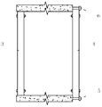
- each layer of glass bonding strip material 6 made of glass or wood with low thermal conductivity and square cross section, and bolt holes 7 on it;
- the door leaf or sash 1 can be integrally embedded in the frame 2 when it is closed.
- a blocking surface 3 is arranged in the frame, and a sealing strip 4 is mounted thereon, so that the closed door leaf or sash forms a sealing surface around;
- the characteristics of the above doors and windows are composed of multiple layers of glass.
- the connection of the glass is realized by several bolts around the glass to clamp the glass frame (or wooden frame, etc.) between the glass, which can form a multi-layer cavity and avoid cold.
- the thermal bridge b) the distance between the glass and the number of layers of the glass can be arbitrarily selected without affecting the structural strength; c) can achieve any thermal insulation performance by controlling the distance between the glass and the number of layers of the glass.
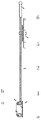
- the bolt holes of the solid plate 4 are the same; then the glass plates 5, 6 are penetrated by bolts 47, and the two ends of the bolts 47 are respectively fixed to the fastening plates 4 and 7; the upper portion of the fastening plate 7 is provided with a connection hole of the bolts 47 ( See rear view 6), the lower side is provided with metal plates 7a, 7b with holes, and the metal rod 7c is connected to the hole; the metal rod 7c can be rotated in the holes of the metal plates 7a, 7b, and one end is provided with a metal ring 7d, and the other end is provided with a metal ring 7d
- the blocking member is fixed to the metal rod 7c by welding or the like to prevent the metal rod 7c from sliding laterally; another fastening plate 8 is mounted on the innermost glass plate 3 (see side view 7), and the upper side is provided with a hole Metal plates 8a, 8b (see top view 8), metal rods 8c are connected to the holes; metal rod 8c has the same structure as 7c, metal ring
- the direction of the metal rings 8d, 7d can be aligned so that the bolts 87 can pass therethrough; then the metal rings 8d, 7d are each fixed to the bolts 87 with nuts on both sides.
- the nut of the rotating bolt 87 abutting against the metal ring 8d can expand or reduce the distance between the fastening plates 8 and 7, and realize fine adjustment and fixation of the longitudinal position between the layers to avoid misalignment caused by gravity or other reasons. Deformation.
- each layer of glass shall be grooved along the positions of the bolts 87, 47 (the strip frame sandwiched between the glass plates shall have sufficient thickness at this position to avoid opening the cavity between the glass when the groove is opened; the glass plate 5, 6
- the place where the bolts 47 are penetrated shall not be grooved.
- the cross section of each groove shall be narrow and wide at the outside, and the depth shall be such that the bolt is completely buried in the groove; then the rubber strips are embedded in the groove to seal the bolts 87, 47.
- the innermost glass sheet 3 can be thicker than other layers of glass, which increases strength and saves material;
- the fastening plate 1 is mounted on the innermost door leaf or sash in the same way as the fastener is installed (see top view 9); the fastening plate 1 is provided with a cylinder a, For connecting the door frame or window frame; the cylinder a is extended downwards and integrated with the lower fastening plate 2 (see Rear view 10); mounting a perforated metal plate a1, a2, b1, b2 on the door frame or window frame (see rear view 10); inserting a bolt c into the hole of the metal plate a1, and inserting a bolt d into the hole of the metal plate b1
- the metal plate e is provided with screw holes a3, b3, the bolts c, d are respectively screwed into a3, b3, and then continue to rotate and pass through the nuts a4, b4 and the metal plates a2, b2 respectively; then at the end points of the bolts c, d Screw on the nuts a5, b
- the hole b6 on the metal plate e When connecting, the hole b6 on the metal plate e is aligned with the cylinder a on the fastening plate 1, and then the bolts c, d are rotated to move the metal plate e until the hole b6 is sleeved on the column a; the upper and lower hinges of the door and window are connected You can also fine-tune the up and down position of the door and window by turning the bolts c and d (and the corresponding bolts on the other hinge); after all the adjustments are completed, the nuts a4, a5 and b4, b5 on the bolts c and d should be tightened. Tighten the corresponding nut on the other hinge.
- a bearing frame can be provided at the hole b6 of the metal plate e and the bearing can be mounted, and then the bearing can be sleeved on the cylinder a (the cylinder a passes through the bearing and the metal plate e at the same time).
- the device can be reverse symmetrical, as shown in Figures 11 and 12, where a is the upper fastener and b is the lower fastener; a1 is the upper hinge , b1 is the lower hinge. If one side is provided with fasteners and hinges at the same time, the hinges on both sides should be hinged, and the fasteners in the middle position.
- the number of each side fastener depends on the weight and thickness of the door and window, and there must be no less than one on the vertical side. On a large weight of doors and windows, the number of hinges can be set;
- the sealing strip 1 is mounted on the base 2; the base 2 is provided with a cylindrical rail 3, a spring 4, a moving block 5; and the upper end of the rail 3 is provided with a screw 6 , thereby preventing the moving block 5 from leaving the guide rail; the moving block 5 is provided with a sliding hole 7 which can slide up and down within the range of the guide rail 3; the lower part of the closing strip 1 is embedded in the base surface 8; the base surface 8 is connected by the screw 9 On the screw hole 5a of the moving block 5; under the action of the spring 4, the base surface 8 is always topped up, and the sealing strip 1 is pressed against the door leaf or the sash to provide a good sealing effect.
- the base 2 should be installed in the tweezers 10 made of low thermal conductivity materials such as glass or wood; the tweezers 10 should have sufficient width to form good insulation; the tweezers 10 on the four sides of the door frame or window frame should be connected as a whole. And the four sides of the base surface 8 and the closing strip 1 are connected end to end (uninterrupted) to achieve a completely closed effect.
- the guide rail 3, its spring 4, and the moving block 5 can be continuously arranged along the closed line (the length of the closed line is unlimited), so that the base surface 8 of any length and the sealing strip 1 can be installed, and a good simultaneous closing and opening is ensured. There is only a small gap between the opening of the tweezers 10 and the sealing strip 1.
- the spring 4 should have sufficient strength (while the sealing strip 1 should have sufficient elasticity) so that the sealing strip 1 is close to the door leaf or The sash expands slightly to the sides to fill the gap; when the door and window are opened, the shape of the sealing strip 1 is restored and the gap is restored.
- double screw holes 5b, 5c may be provided on the moving block 5, and two adjacent base faces are respectively connected. If the sound of the metal sliding on the guide rail 3 is to be reduced when the door and window are closed, the sliding portion should be smoothed, or the glass sheath should be placed on the guide rail 3, and then the spring 4, the moving block 5, and the like should be mounted.
- the material of the above-mentioned energy-saving doors and windows can also be used with other materials with low thermal conductivity and high strength (this is also applicable to glass curtain walls and glass roofing).
- the combination of such doors and windows with the thermal insulation roof, the thermal insulation floor and the exterior wall of the curtain wall brick can make the insulation of the house cover all parts and achieve the purpose of high efficiency and energy saving.
- in terms of appearance if it is simply the use of curtain wall exterior walls, it is not feasible in modern buildings. Only by improving the thermal insulation performance of various curtain walls and decorative walls and stucco walls to the same level as the exterior walls of curtain wall bricks, and greatly reducing the construction cost, can the energy-saving houses be popularized. Below are solutions to these problems.
- A) Glass curtain wall The energy-saving doors and windows mentioned above can be arbitrarily superimposed with insulating glass, and the distance between the glass can be arbitrarily selected, so that the heat insulating layer can reach or exceed the brick wall with the insulating layer. Between this, as shown in Figures 15 and 16, the same as the above-mentioned door leaf and window sash can be used.
- the corresponding process of the point curtain wall (such as cable, connecting rod) can be applied to further increase the safety performance; if the large glass wall 4 is installed outside the floor
- the embedded parts 5, 6 can be arranged to support and fix the glass outer wall.
- the glass curtain wall constructed by this method (especially when the glass wall is all installed on the outside of the floor), in addition to fundamentally solving the problem of heat insulation, is not inferior to the traditional glass curtain wall in appearance; and its strength and life can exceed the latter. .
- the innermost glass is thicker, the other layers can be thinner, and the amount of metal is greatly reduced, and the total weight is comparable to the frame type curtain wall.
- the energy-saving glass curtain wall uses more glass than the point glass curtain wall, but it is a self-supporting structure, which greatly saves the support material of the point curtain wall (the cable and the connecting rod are only used as safety measures to prevent falling, without having to It is used to fix the position of the glass), so the cost is reduced.
- the glass is also used more than the frame glass curtain wall, but the cost-saving frame of the frame curtain wall is saved, so the cost can be greatly reduced.
- the front half of the members a, b are vertical metal plates with holes therein; the rear half is horizontal metal plates) And can be embedded in the joints; the two ends of the member c can slide in the holes of a, b, the threads are matched with the rotating nut d provided outside the member b; the nut d is connected to the member b and can be rotated Its blocking member e can prevent it from coming off the member b.
- the two ends of the member c are inserted into a, b, respectively, and then passed through d at the point b by the rotation of d.
- the members a1, b1, c1, and the nut d1 are the same as a, b, c, and d, respectively, but are embedded in the lower layer joint; the two ends of the member c1 are respectively inserted into a1, b1, and then the rotation of d1 is performed at b1. Pass through d1.
- the members f, f1 are threaded and provided with nuts d2, d3, respectively; the nuts d2, d3 are connected in the holes of the member c and are rotatable, and the blocking member e1 can be prevented from coming off the member c.
- the members f, f1 respectively pass through the two fixing nuts d22, d33 on the member g and the guiding holes in the lower portion of the member g (when the nuts d2, d3 are rotated, the nuts d22, d33 can move the member g up and down).
- f, the lower part of f1 is inserted in the corresponding hole on c1; the length of f and f1 is greater than the distance between the joints of the upper and lower embedded parts.
- f, f1 are respectively connected at the midpoints of c and c1, which can prevent the holes of a, b, a1, and b1 from slipping when c and c1 move horizontally; the length of c and c1 should be such that when moving on one side, the other is There is still a portion of the hole that is beyond the hole.
- the metal plate g1 with the two bolts f11, f22 is passed through the lateral guiding holes h1, h2 on the member g and the rotating nuts d4, d5 provided on the rear side (the nut structure and d, d1 is the same) and connected to the component g. Then, the metal plate g1 is moved left and right by rotating the nuts d and d1, the metal plate g1 is moved up and down by turning the nuts d2 and d3, and g1 is moved back and forth by rotating the nuts d4 and d5.
- the outside of the metal plate can be set at a right angle to form a stepped shape, which is hooked in a short groove opened on the side of the stone panel. Since the metal plate can be moved in three dimensions and can be finely adjusted by the rotation of the nut and nut, the stone panel can be accurately mounted to the desired position.
- a stone panel can be fixed by four stepped metal plates. After the four metal plates have been installed, when the fine adjustment is made, the rotating nut and nut of the lower side and the inner metal plate position are rotated by the elongated sleeve or the driven sleeve and the wrench.
- Each of the above stone panels is directly installed on the embedded parts of the brick-concrete exterior wall, eliminating the huge metal frame, saving a lot of materials, which can greatly reduce the cost; at the same time, the stone panel and the outer wall are reduced. The distance helps to increase strength and service life.
- the cavity can be set according to the exterior technology of the curtain wall brick, the cavity is filled with heat-insulating cotton, and the metal piece is connected with the innermost curtain wall brick.
- the process is exactly the same as the curtain wall exterior wall technology, but the opposite direction: the curtain wall brick is located inside. For convenience, below This process is called curtain wall interior wall technology.
- the thermal insulation performance of the stone curtain wall can fully meet the requirements; at the same time, the interior wall of the curtain wall brick can be directly used as a good interior decorative wall surface.
- Ceramic curtain walls and metal curtain walls are easier to install than stone curtain walls because of their plasticity.
- a short groove may be provided on the side of the ceramic plate, the metal plate or the like (or the inner side is close to the edge), and the stone stone wall is directly installed on the embedded part of the brick-concrete outer wall according to the above-mentioned stone curtain wall process; meanwhile, the thermal insulation is installed according to the interior wall technology of the curtain wall brick.
- Floor and curtain wall tiles Its heat insulation performance and cost are similar to those of the above stone curtain wall.
- the insulation of the decorative wall and the painted wall can also be carried out completely according to the interior wall technology of the curtain wall: a cavity is arranged inside the outer wall, the cavity is filled with heat insulating cotton, and the metal piece is connected with the innermost curtain wall brick.
- the curtain wall brick is located on the inner side, and does not affect the decoration and painting of the outer wall, so the proportion of the wall is not limited.
- the interior wall of the curtain wall brick can be put into use as an interior wall.
- slotting can also be used instead of punching; one end of the reinforcing bar 4 is wound into a ring a and the joint is welded, and the other end is bent into a hook shape (the other end can also be processed into other shapes that are advantageous for preventing loosening of the reinforcing bar) Or replace the steel bar with a casting or the like) and insert the hole 2; make the steel bar 5 (including the ring a1) and insert the hole 3 in the same manner; then fill the holes 2, 3 with the mortar, and make the rings a, a1 coincide.
- Holes 6, 7 are to be parallel to the holes 2, 3 and have the same shape and size; then the same steel bars 8, 9 as the steel bars 4, 5 (with rings a2, a3 respectively) are inserted into the holes 6, 7, fill the holes 6, 7 with mortar, and make the rings a2, a3 coincide.
- the bolt 10 or the large rod
- the bolt 10 is passed through the rings a2, a3, and the nut is screwed at the lower end (or the lower end of the big head member is attached with a fixing member).
- the steel bars 11 When laying the curtain wall bricks in the later stage, the steel bars 11 can move up and down, and smoothly bury the brick joints of the curtain wall bricks to complete a firm connection.
- the multi-layer any controllable thermal insulation structure described in the foregoing can be applied, and the appropriate materials can be directly installed on the original wall, roof, floor, doors and windows, etc.
- the appropriate materials can be directly installed on the original wall, roof, floor, doors and windows, etc.
- Figure 1 is a door leaf or window sash; Figures 3, 4 are door frames or window frames; Figure 5 is a top view of the fastener connection; Figure 6 is a fastener connection Figure 7 is a side view of the fastener connection; Figure 8 is a plan view of the fastener connection; Figure 9 is a top view of the hinge connection; Figure 10 is a rear view of the hinge connection; Figure 11, 12 is the reverse symmetry of the fastener or hinge; Figures 13 and 14 are the closure of the door frame or window frame; Figures 15 and 16 are the energy-saving glass curtain wall; Figure 17 is the side view of the energy-saving stone curtain wall; Figure 18 is the rear view of the energy-saving stone curtain wall Figure 19 is a cross-sectional view of an energy-saving decorative wall and a stucco wall; Figure 20 is a rear view of the energy-saving decorative wall and the stucco wall; Figure 21 is a top view of the energy-saving decorative wall and the stucco wall connector; Figure 22 is a brick-connected curtain wall brick Figure
- FIG. 39 is a side view of the cable or tie rod connection;
- Fig. 40 is a plan view of the cable or tie rod connection;
- Figs. 41 and 42 are the assembly of the thin glass wall block;
- Figs. Figure 45, 46 is a front view of the wall hanging installation;
- Figure 47 is a side view of the wall hanging installation;
- Figure 48 is a front view of the inflatable film structure hanging installation;
- Figure 49 is a pneumatic film structure suspension
- Figure 50 is a pressure air bag;
- Figure 51 is a rear view of the inflatable film structure upside down;
- Figure 52 is a side view of the inflatable film structure upside down;
- Figure 53 is a built-in telescopic air bag;
- Figure 54 is a telescopic air bag
- Figure 55 is an arrangement of energy-saving stone curtain wall, ceramic curtain wall, metal curtain wall connector;
- Figure 56 is an elongated sleeve;
- Figure 57 is a rear view of the transmission sleeve;
- Another common practice is to first install a waterproof and sealing layer on the roof to ensure that the roof is not leaking or vapor-permeable; then install the insulation layer directly on the waterproof and sealing layer (using non-absorbent insulation material); then in the insulation layer A breathable protective layer is provided.
- the insulation can be installed under the roof. Due to the protection of the roof, the insulation will not be exposed to direct sunlight and will not rain. Therefore, the above ventilation layer and the waterproof layer and the protective layer can be omitted (but the lower sealing layer cannot be omitted), and various insulation can be used. material.
- the insulation layer needs to cover the lower layer of the entire roof. If there is a strong enough support surface under the roof, the insulation layer can be installed directly on it; otherwise the support surface must be installed first.
- the insulation layer is installed inside the wall, the above safety, strength, performance, appearance and the like can be solved.
- a thermal insulation layer is placed in the wall, a cavity is formed, and the strength and seismic performance of the cavity become a problem to be solved when the wall area is large.
- the curtain wall exterior wall technology described above can provide a proper solution, and can also arbitrarily adjust the thickness of the cavity and its insulation layer, so that the outer wall can achieve the required insulation performance.
- the structural frame of the house may form an unfavorable cold and heat bridge for extreme climatic conditions and temperature differences.
- a reinforced insulation layer is required to be installed in the structural frame of the room. Because this is a partial, small-area insulation installation, it can be properly covered by the interior design.
- the technology can be extended as follows:
- the bolt is sleeved with a sleeve with low thermal conductivity and a certain strength and hardness (can be made of glass, etc.
- the sleeve should be sized to fit the bolt without leaving a gap; the wall is more Thick, more conducive to heat insulation), then put the hoop steel bar on top, thus forming a cold and hot broken bridge, further reducing heat transfer;
- c) widen the width of the curtain wall brick to about 20cm, so that it can be paved independently and obtain sufficient strength without connecting with the inner wall (but the upper and lower walls should be connected with the floor or the frame of the house, and avoid being made in the hall. Excessively unconnected paving or paving from the frame. The following d, e, f are the same). Although the overall thickness of the outer wall is increased, the heat transfer of the metal parts can be omitted (although the heat transfer amount is small), and the heat insulation performance is further improved;
- the inner and outer walls are made of concrete blocks, and the joints between the inner and outer walls are omitted. In this way, the exterior wall needs to be decorated, but the wall itself can reduce the cost and speed up the paving. This approach is advantageous for buildings that do not have a real brick wall appearance;
- the inner and outer walls are made of hollow brick walls with a width of about 20cm, and the connection between the inner and outer walls is omitted. If you use the appearance of a brick wall, the exterior wall does not need to be decorated; if you use other appearances, you need to decorate it. In areas where the price of hollow bricks is very low, this approach also has advantages;
- Concrete blocks are used for the outer walls, and the inner walls are independently paved with bricks of sufficient size to eliminate the connection of the double walls.
- This method is also feasible under certain conditions. (For example, if the exterior wall needs to be painted with a wall, and the interior can be used with brick walls, this method can be better than the way in d);
- hollow brick walls are used for both inner and outer walls (if the house is not high, technically, solid brick walls can be used, but the consumables are large and heavy), one of which can be smaller in width; the inner and outer walls are connected by metal parts to achieve Sufficient strength. It is also possible to directly connect the inner and outer walls with bricks as shown in Fig. 22: the bricks 1, 2, 3, 4, and 5 are the same size, the bricks 5 are horizontally connected, and the inner and outer walls are connected; the ends of the brick 5 are small and half bricks 6, 7 Paving. For ease of construction, it is also possible to produce bricks 8 dedicated to the lateral connection; the length of the bricks 8 is equal to the length of the bricks 5 plus bricks 6, 7 (including their seams). When laying bricks 5 or bricks 8, the amount of bricks 5 or bricks 8 should not be too much (one to two per square meter), because too much transverse bricks will increase heat transfer; the amount can not be too small to ensure sufficient strength.
- the curtain wall brick with a thin concrete block and connect it to the main wall by bolts or the like.
- the thin concrete block needs to be painted and decorated; in the interior wall structure of the curtain wall brick, the interior decoration is also required.
- the thin concrete block can further reduce the cost and further reduce the weight. If it is used for thermal insulation decoration of the existing decorative wall, stucco wall, stone curtain wall, ceramic curtain wall, metal curtain wall, etc., the connection method in the foregoing invention 2D (Fig. 19, 20, 21) can be applied.
- the exterior wall of the curtain wall and various brick walls and concrete walls with cavities will form a breathing mechanism: the gas is discharged when the wall is heated, and the gas is sucked when it is cold.
- the wall can be sealed, and only a plurality of air filter tubes are arranged in the house: as shown in Figures 23, 24 and 25, the air filter tube 1 is slightly inclined (about 5°) and fixed at the base.
- the lower section of the air filter tube 1 is provided with a stainless steel mesh 2 (this mesh can be stacked in multiple layers and separated from each other by a certain distance), the upper section is provided with a quicklime passage 3; the lower part of the passage 3 is provided with a blocking plate 4 to block The quicklime that turns into powder slides down; the quicklime is placed in the lime channel 3, but does not exceed the height of the barrier plate 4; the upper side of the channel 3 is provided with a transparent glass 5 (or other transparent material) for observing the condition of the lime and when the lime is replaced Take it down. If you want to lengthen the length of the gas pipe, you can set the route of the pipe to be turned back and forth and close to each other (see top view 24).
- the limestone part of the pipe can be leveled and the number of the block can be reduced; It needs to be set to be inclined, which can be "Z" shape (see front view 25) or spiral, so that its channel continues to drop, avoiding the condensation when the condensation occurs.
- the stainless steel mesh part of the pipeline shall be made of metal and placed in a cold water container to facilitate condensation of water vapor; the upper end of the filter gas pipe is connected to the wall, and the lower end is passed through the cold water container followed by a funnel and a drain pipe (not directly connected to the drain pipe to avoid inhalation Wet gas in sewers, etc.). After the quicklime turns into powder, the new quicklime is replaced; other quick water can be used instead of the quicklime.
- a lime basin or other absorbent material can be placed in the cavity in the wall close to the drainage and detection holes and replaced periodically.
- energy-saving rooms can also use energy-saving curtain walls (glass curtain walls, stone curtain walls, ceramic curtain walls, metal curtain walls, and curtain walls of other materials), as well as energy-saving decorative walls and stucco walls.
- the roof of the energy-saving house can also be used with a multi-layer glass roof (see Implementation A of the energy-saving glass curtain wall below) or a low-heat-conducting roof with the same structure.
- Fastening devices for the side of glass panels or other low-heat-conducting materials such as doors and windows and exterior walls can be made of metal or other high-strength materials.
- Spacers shall be provided between the glass plates and the bolts and other metal connectors to prevent damage to the glass (this applies to the glass plate assemblies mentioned below, and will not be repeated for convenience).
- the transition chamber can be set as shown in FIG.
- the door 1 and the door 2 are in a normally closed state; when the door 1 is opened, the door 2 is closed, and when the door 2 is opened, the door 1 is closed, which greatly reduces the heat conduction of the air.
- the metal plate e on the frame is adjustable up and down; if it is set to be left and right,
- the smooth perforated metal plates 1, 2, 3, 4 can be laterally embedded or installed in the manner of the rear view 27; and the threaded metal rods 5, the metal plates 3, 4 are provided in the holes of the metal plates 1, 2 in advance.
- a threaded metal rod 6 is arranged in the hole; the metal rod 5 is vertically provided with holes a1 and b1, and the metal rod 6 is vertically provided with holes a2 and b2.
- the remaining connections are identical to Figures 9 and 10.
- the metal plates 1, 2, 3, and 4 in Fig. 27 can be set to the structure of the metal plate 7 in the side view 28: the bolts 7a, 7b are embedded or mounted on the frame. At the same time, the inner and outer positions of the metal plate 7 can be adjusted by rotating the nut thereon.
- the metal plates 2, 4 in Fig. 27 may also be disposed on the right side of the holes b1, b2 while extending the metal rods 5, 6 on the right side and passing through the holes in the metal plates 2, 4, respectively; The metal rods 5, 6 can be directly inserted into the holes in the metal plates 2, 4 without being connected by welding or the like in advance, and it is advantageous to increase the strength of the metal rods 5, 6.
- the length of the metal plate e otherwise it cannot exceed the position of the metal plates 2, 4 to reach the connector on the door leaf or the sash. If the length of the metal plate e is not lengthened, the length of the connector on the door leaf or the sash needs to be lengthened so that the length of the metal plate e is increased. Reach the metal plate e.
- the rotating shaft on each connecting piece should be set in pairs, not only one; at the same time, the metal plate on the door frame or window frame e They should also be arranged in pairs so that each connector can be clamped so that it can be independently supported, thereby greatly reducing the stress on the door and window panels.
- the doors and windows vertically arranged on the rotating shaft are Lateral length on the door and window panels It can be set up to support a wide range of doors and windows; windows that are placed laterally to the shaft are also more secure than single-shaft connectors.
- the cross section of the metal plate e can be set to "L" shape, "[" shape, or square shape, etc., and its bending strength is much higher than that of the flat plate shape.
- the position of the door leaf or the sash is moved inward, and the effect of the depression may occur.
- the hinge device is installed on the door frame or the window frame, if the device is not hidden under the surface of the outer wall, the position of the door leaf or the sash may move inward or may occur. The effect of the depression. If you want to make it flat, you can also use the small panel.
- Doors and windows open to the outside and inside shall be provided with a sump and a drainage pipe at the bottom of the frame, and the drainage pipe shall be connected to the drainage pipe inside the house or directly connected to the outside of the wall.
- the insulation of the lowest floor of the energy-saving room can be carried out according to the following scheme: a) waterproofing and sealing layer installed on the lower layer; b) waterproofing and insulation layer on the sealing layer with non-absorbent insulation material; If the material is laid, a waterproof layer shall be added on the insulation layer; c) the joist shall be erected on the insulation layer and the waterproof layer, and the joist shall be provided with a certain space above the insulation layer to form a ventilation layer and a vent; d The floor is erected on the joist.
- the insulation of the floor is only required to be carried out on the lowermost floor of the house. If the house has a multi-level basement and the soil around the foundation is dry, there is no need to provide insulation on the floor and perimeter of the lower basement. If the basement of the house is a garage or the like and there is no insulation, the insulation on the first floor of the floor is required.
- the thickness (not just the thickness of the insulation layer). Due to various The thermal conductivity of the material is different. If there are many materials to choose from, the material needs to be determined before determining the thickness. After the material is determined, the thickness can be determined according to the heat insulation requirements; then the theoretical calculation and specific experiments are carried out to ensure the heat transfer of each part. The coefficients are similar or matched, and no bottlenecks occur.
- the ventilation of the kitchen and bathroom can be directly connected to the outdoor, but the inner wall and the door must be insulated (this insulation layer can be insulated lower than the outer wall, because the ventilation of the kitchen is only required during cooking, and the ventilation of the bathroom is not It is necessary to exceed a certain speed, the temperature of these spaces is different from the outdoor.
- the insulation layer should be set based on the temperature of its space), and it can be insulated to reach the predetermined level of the whole building.
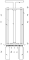
- the support members 1, 2, 3, 4 can be embedded in the frame of the floor of the first floor, and the support members 5, 6, 7, 8 are embedded in the frame at the top of the floor; 1 and 2, 3 and 4, 5 and 6, 7 and 8 are respectively close to each other to enhance safety (if one of the groups is damaged, the other must be able to carry all of its weight); each support member is provided with a thread, and the length of the support member is exceeded.
- the thickness of the glass wall is used to install the nut; the side of the glass wall 9 is provided with fastening means (the specific configuration is shown in Figures 5, 6, 7, 8), thereby preventing misalignment and deformation between the layers of glass.
- the glass wall 9 is placed on top of the support members 1, 2, 3, 4, 5, 6, 7, 8 and then a gasket and a nut are mounted on the threads.
- a certain gap should be left between the glass wall 9 and the supporting members 5, 6, 7, 8 as the expansion joint, and the upper ends of the expansion joint and the glass wall should be completely covered behind the nut and the gasket. All supports must support the weight of the respective upper glass wall while fixing the position of the respective lower glass walls.
- the cross section of the support member and the glass contact section should be square and horizontally arranged to increase the contact surface with the glass wall; the cross section of the support member beyond the glass portion should be circular to provide threads and nuts. If the weight of a glass wall is large and the two sets of supports are insufficient to carry, the number of supports on the same glass wall should be increased.
- the upper and lower positions of the support members should be made adjustable: glass can be carried on each support member. Place two screw holes in the up and down direction, and then screw the two bolts vertically (nut up); turn the nut to reach the uniform level of the same floor and tighten the nut at the lower end of the bolt; Connect the two nuts to the same rectangular metal cover (the metal cover should have sufficient thickness and width to reduce the load per unit area when carrying the glass), and increase the diameter of the transverse nut and the washer on the support.
- the glass wall is out of its barrier range.
- Expansion joints shall be provided in the transverse direction between different glass wall blocks; the transverse and vertical gaps between adjacent glass blocks shall be sealed. Tempered glass is used where people pass and stay.
- the section of the upper and lower seams of the glass wall shall be set in the manner shown in Figure 31.
- the inside and outside of the upper and lower walls are horizontal, and the outer sides are inclined by 3 and 4, which This prevents rainwater from seeping into the interior of the wall or inside the house.
- the outer side of the glass shall be flattened on the glass block on the upper side of the joint so that the support member passes through the ground groove (it may also be formed into the same shape by direct molding or the like), thereby
- the layers of the glass wall are placed on the support member; on the glass block below the seam, the outer side 4 of the glass should be prevented from being machined into a bevel, but should be kept in its original shape (the cross section is a right angle) to avoid the support member.
- the nut and gasket do not have enough contact or sufficient contact surface to prevent sufficient sealing and fixing. A good waterproof seal is required with the sealant at the position of the support.
- each layer of glass except the outermost layer of the glass wall shall be provided with a small hole for filling with inert gas and sealed; in case the glass is atomized by the water in the glass wall, the water vapor may also be passed through the small hole. Discharge; the pores of each layer should be opposite so as to be blocked or opened at the same time. (All the glass walls and roofs below should be provided with such ventilation holes. The doors and windows should also be equipped with ventilation holes).
- the inside of the glass wall of the house should be equipped with anti-theft devices at the necessary positions: as shown in Figures 1 and 2, the bolts 8 can be lengthened and a nut can be added on the inside, and then connected to the anti-theft bar fixed at the frame of the house.
- the connection manner of the anti-theft lever can be as shown in FIG.
- the two ends of the anti-theft bar 1 are wound into a ring shape and welded to the end point; the ring a of the anti-theft bar 1 is connected to the bolt 2 of the glass wall by the nut a1 (the ring a and the bolt 2) Insulation sleeves shall be provided, and insulation rings a2 and a3 shall be respectively provided on both sides of the ring a; the heat insulation sleeve and the heat insulation ring may be made of materials such as glass with low thermal conductivity and hardness and strength, and the greater the thickness, the better.
- the bolt 3 is provided with a nut 4 and a thick metal gasket 5; the ring b of the anti-theft bar 1 is sleeved on the bolt 3 and fixed by the nut 6; the bolt 3 is inserted into the hole of the metal plates 7, 8; the metal plates 7, 8 are fixed in the house A frame or a floor panel; the outer side of the metal plate 8 is screwed onto the nut 9.
- the anti-theft lever 1 will be tightened (can not be pulled too tight to damage the glass).
- the anti-theft bar 1 is first mounted on the bolt 3, then the bolt 3 is mounted on the holes 7, 8 and then the glass wall is installed, and finally the anti-theft bar 1 is attached to the bolt 2.
- the end of the bolt 2 shall be provided with a bolt to prevent the nut a1 from being detached from the bolt when the nut outside the wall is screwed, and a blocking member shall be provided on the frame or the floor of the wall to prevent the anti-theft lever 1 from rotating with the bolt 2 (if the bolt 2 is to be bolted 2
- the position of 3 is set close enough to the frame or floor of the house to prevent the security bar 1 from rotating continuously. To make the anti-theft lever 1 more evenly distributed on the glass wall, it can be symmetrically placed (like a basket bolt).
- the positions of the metal plates 7, 8 should be accurate, and the dimensions of the anti-theft bar 1, the bolts 2, 3 should be uniform.
- the bolt 2 and its nut a1 are required to be equipped with a heat insulating cover (see the contents of FIG. 1Bd and FIG. 2); since many components are added to the bolt 2, the heat insulating cover cannot be installed on the nut a4, and the The insulation ring is placed over it.
- the embedded parts of the above glass wall can be directly mounted on the steel structure, and the rest of the installation is exactly the same. Since the insulation layer is located outside the house, it can eliminate the disadvantages of steel structure insulation.
- the above glass wall can also be installed as a lighting roof in a lateral or oblique direction on the roof.
- a strong supporting structure must be provided (the supporting structure must fully support the weight of the roof and bear the maximum possible rain and snow load, wind load, earthquake shock, etc., and must achieve the predetermined anti-rust, anti-corrosion and anti-aging properties. All roof support structures must be the same); the specific way depends on the shape and structure of the building.
- a removable reflective film is needed to prevent adverse greenhouse effect or heat radiation.
- the installation of the movable reflective film can be carried out in the manner of Figures 33, 34, 35, 36, 37, 38: the rotating shaft 1 and the rotating shaft 2 are respectively mounted on both sides of the glass block (see side view 33); The area of the reflective film 4 can reach the entire range between the rotating shafts 1, 2; the two sides of the reflective film 4 are connected to the guide rail 3 through a plurality of connecting members 5 (see front view 34, which is clearly shown in the figure, enlarged).
- the connecting member 5 is provided with pulleys a, b, c, d and pulleys a1, b1, c1, d1 (see rear view 35, which is clearly shown in the figure, enlarged), and can slide on the guide rail 3; the reflective film 4 One side of the connecting brace 6 (see side view) 33), the length of which is equal to that of the reflective film 4; the connecting member 5 is also provided on the brace so as not to be separated from the guide rail 3.
- the rotating shaft 2 When the reflective film is unfolded, the rotating shaft 2 is rotated by a motor or a manual method, so that the brace is wound around the two ends of the rotating shaft 2, and the reflective film 4 is pulled along the guide rail 3; when the reflective film is removed, the rotating shaft 1 is rotated by a motor or manually.
- the reflective film 4 is pulled up along the guide rail 3 and wound around the rotary shaft 1.
- Both ends of the guide rail 3 are provided with inclined faces 7 and 8 with pulleys (see bottom view 36 and sectional view 37); the gap between the inclined faces 7 and 8 can only pass through the reflective film or the brace, and the pulley thereon can connect the connecting piece
- the position of 5 is extrapolated and pushed up to guide it to the guide rail 3.
- the connecting member 5 and its pulley need to be made of a lightweight material such as plastic and use a minimum size under the premise of ensuring strength; and the pulley should be completely covered inside the outer casing of the connecting member 5 to prevent the connecting members from being entangled on the rotating shaft. Knot. With such a hinge connection, as long as the material of the reflective film is light enough, it can cover a large width (the width of which is mainly limited by the shafts 1 and 2: if the shafts 1 and 2 are too wide, it is inconvenient to install); The length is almost unlimited.
- a cable ring 9 can be provided on the connecting member 5 according to the front view 38, and the rotating shaft 1, 2 and the inclined surfaces 7, 8 in the rotating shaft connection can be eliminated, so that the reflecting film 4 and the pulling film are pulled.
- the strip 6 can be moved over the guide rail 3 by the pulling of the cable in the cable loop 9; the cable can be operated by motor or manually.
- the reflective film or the strip is folded after being moved to the end, and is made of a material that does not easily leave a crease.
- the middle section of the cable is connected at the junction of the reflective film and the brace so that it can be pulled on both sides to realize the unfolding or folding of the reflective film.
- the cables on the two side rails can be rolled together for synchronous operation.
- the folding connection needs to occupy a certain area after the reflective film is folded; if it is to avoid occupying the plane of the roof, the guide rail 3 can be extended downward or upward on the inner side of the outer wall to move the folded reflective film to the outer wall.
- the distance between the connecting members 5 is increased on the guide rails 3, the plane occupied by the roof after the folding of the reflective film can be reduced.
- hinge type and folding reflection film can be applied to the roof as well as other positions.
- the roof should generally have a slope and there should be a good overlap or seal between the glass blocks.
- the glass curtain wall is not less than any other glass curtain wall, and the design life can be greatly extended.
- the glass wall If the glass wall is installed between the floors, it is not good for the overall insulation of the house, but compared to the way of installing the outside of the frame, the glass wall can be assembled with smaller glass, and the glass wall can be omitted. Side fastenings. The feasibility of applying this method under many conditions (such as areas that are not too cold or too hot) is available. At this time, the size of the glass wall block is smaller than the distance between the floors, and the glass wall block can be laid up and down (depending on the size of each wall block, one or more layers can be paved; the smaller the size of the wall block is, the more unfavorable for heat insulation), Each wall block should be bolted to the cable or tie rod.
- the two ends of the connecting member 1 are respectively provided with rings a, b (see side view 39); It is fixed on the bolt of the glass wall (the heat insulation sleeve and the heat insulation ring should be respectively provided between the bolt and the nut, which is the same as the anti-theft lever in the energy-saving glass curtain wall implementation A above); the connecting member 2 is provided with a hole a1 , b1 and "U" bolts 3 (see top view 40, shown clearly in the figure, enlarged).
- the connection between the cable or the tie rod and the floor can be completed by pre-embedded parts on the floor; the embedded parts can be set up with 4 perforated metal plates and connected in a two-dimensional adjustable manner in the door and window hinges (see the summary). 1Db and FIG. 10, and the implementation of the energy-saving room C and FIG. 27), so that the position of the cable or the tie rod can be adjusted in the front, rear, left and right directions.
- the cable or tie rod needs to further prevent the wall from falling off on the basis of the structural rubber wall joint and can pull the whole weight; as long as it can achieve this purpose, the setting does not have to be too thick or too tight.
- This glass curtain wall is not lower than that of any other glass curtain wall, and the design life can be greatly extended.
- expansion joints shall be provided at regular intervals; in the vertical direction, the structure, material, climate and other relevant conditions of the house shall be investigated to determine whether or not to provide expansion joints. If the joint has a certain thickness and uses a flexible silicone structural adhesive, it can play a certain expansion joint function. If the telescoping of the house frame is larger than the wall, more detailed calculations and experiments are required.
- temperred glass is used where people pass and stay.
- Static glass walls are generally not subject to shocks and shocks such as doors and windows.
- shocks and shocks such as doors and windows.
- the outermost side for theft prevention
- only a thick layer of glass can be placed on the innermost side; at the same time, the other layers of glass are greatly thinned, and Keep the frame between the glass from thinning. This minimizes the weight of the glass wall without reducing its overall strength and thermal insulation properties.
- a thick layer of glass can be placed on the innermost side at the same time.
- the outermost glass In areas with strong winds or high-rise buildings, if the outermost glass is a large piece of thin glass, it is necessary to focus on the calculation and test of the wind load to prevent the glass from being damaged by the wind; if the wind is too strong, it must be changed to the corresponding thickness. Glass with strength (the same is true for all exterior walls with thin glass below). When the glass wall is installed laterally or obliquely on the roof, the glass of the lowermost layer cannot be reduced in thickness; the glass of the middle layer can reduce the thickness; in the uppermost layer where it may be affected by hail, rain or snow load or wind load The glass must also have a corresponding thickness and strength (this applies to all glass roofing and other material roofing below).
- the entire glass exterior wall has a light-transmissive function of the window, and the window on the glass outer wall is only necessary if there is no door on the wall in order to change the air.
- Each layer of glass plates (except the outermost layer) of the wall block shall be provided with an air hole at the upper and lower ends for filling with inert gas, or for water vapor removal in the event of atomization in the cavity; if the wall area is small
- the size of the pores can also be reduced accordingly, while using a colorless closure to avoid affecting the appearance.
- the glass wall blocks built between the floors do not need bolts, cables, pull rods and other connecting parts, so the probability of falling is relatively increased; but if the personnel use the tempered glass completely in the past or stay, and in the house Install railings or protective nets near the glass façade (the same railings or protective nets must be provided for the thin glass walls installed outside the frame of the house), and the safety problem can be solved.
- This glass block curtain wall is comparable to that of a framed glass curtain wall.
- the advantage of the thin glass wall between the thin glass wall on the outside of the above-mentioned house frame and the floor of the house is that the cost is further reduced greatly, even lower than the decorative wall and the painted wall; and the appearance effect is not lower than any glass curtain wall. Coupled with its thermal insulation advantages, it may be more popular.
- a thin glass wall can be laid on the inside of the original glass curtain wall and on the edge of the floor. Due to the increase in the weight of the wall, the load on the structure of the building and the foundation should be calculated and reinforced if necessary.
- Thin glass block walls can also be used as interior partitions. At this point, the number of layers of glass can be reduced, and the smaller wall blocks are laid in the lower part and the larger ones are laid on the upper part.
- the strength of this partition wall is limited, but it has many advantages such as low cost, light weight, heat insulation, sound insulation, beautiful appearance and fast paving speed.
- the glass wall installed between the floors can be insulated with a layer of insulation on the structural frame of the indoor house. This can effectively reduce the effect of the cold and hot bridge caused by the structural frame; the best way is to
- the glass wall is installed outside the frame of the house, or a short wall and a narrow wall which are identical to the glass wall structure and completely cover the frame are provided on the outside of the frame.
- the short wall and the narrow wall may have two or more connecting holes in the middle (the annular spacer is arranged around the connecting hole to avoid the leakage of the inert gas in the cavity of each layer; and the strength at the connecting hole is ensured at the same time) ), and the connecting hole is placed on the bolt embedded or installed at the frame of the house, and then the gasket, the nut and the heat insulating cover are installed at the end of the bolt.
- the thin glass block described above can also be installed as a lighting roof in a lateral or oblique direction on the roof.
- the glass block in addition to the need to completely use tempered glass, the glass block must be mounted on a dense support structure; to install a large-area cemented glass block on a relatively sparse support structure, the lowermost One layer of glass is changed to thick tempered glass, and the middle layer can be thinner.
- the upper layer should be determined according to the possibility of impact and rain and snow load and wind load.
- the air bag can be placed in a convenient place and connected to the ventilation hole in the room or the pipe leading to the outside through a small pipe.
- the round tube can be bonded with a structural adhesive on the glass panel at the indoor ventilation hole, and then the small tube of the airbag is fastened to the round tube.
- the airbag will be propped up; when the glass cavity is cooled by the cold, the airbag will contract. If there are more holes in the wall, the tubules of the balloon can be branched.
- the air bag and the air pipe should be sealed to ensure that no gas is wasted.
- the airbag can be placed in a hollow partition wall.
- the glass partition wall described in the implementation of the energy-saving glass curtain wall can serve as the task: as shown in Figs. 43, 44, a vertical port 2 is left inside the glass block 1; the size of the air bag 3 matches the block 1 and is smaller than the block.
- Block 1 cavity, available from The vertical port 2 is placed in the cavity of the block 1 and can prevent the glass from being damaged when the air bag is full; the back of the air bag 3 is provided with a support rod to prevent it from sagging.
- the airbag 3 is placed into the cavity from the vertical opening 2 at the time of installation, while the other end of the air tube 4 on the airbag 3 is passed through the cover strip 5, and then the cover strip 5 is sealed at the vertical opening 2.
- the tracheal outlet on the cover strip 5 needs to be wider than the tracheal diameter so that the cavity of the block 1 itself is ventilated.
- the cover strip 5 is made of a lightweight material such as plastic, and a fastener is provided to be easily removed and covered when the airbag 3 is observed or replaced.
- the diameter of the gas pipe can be thinner and installed along the joint of the glass wall; at the same time, the glass block 1 can be made of frosted glass, embossed glass, or the like, or the airbag 3 can be made of a transparent material.
- Each air bag and air tube should be regularly tested to avoid blockage or air leakage.
- the above-mentioned energy-saving glass curtain wall, roof and door and window cavity adopts impervious and airtight insulation board in the place where no transparency is needed, and the heat insulation board fills the cavity, the ventilation hole, air pipe and air bag can be omitted.
- the cavity does not need to be layered, and the intermediate layer glass can be omitted; as long as it reaches a sufficient total thickness, the predetermined heat insulation purpose can be achieved.
- this approach comes at the expense of the transparent function of the glass and is therefore limited in scope.
- the breathing mechanism of the exterior wall of the curtain wall and various brick walls and concrete walls with cavities described in B can be implemented, and the exhaust port can also be connected to the airbag.
- the displacement of the exterior wall of the curtain wall in areas with large temperature changes and strong sunlight may be very large; if the airbag does not contain its displacement, it is still necessary to use a gas filter and place a water absorbing material in the cavity inside the wall.
- the gas injection pipe When injecting inert gas into each of the glass walls of the glass curtain wall, the roof and the doors and windows, the gas injection pipe can be inserted into the air venting hole, and holes are formed in each layer of the cavity on the pipe to simultaneously inflate the layers. . If it is necessary to fill different layers of gas, separate the ventilation holes and separate them around the air holes in different cavities to avoid mixing of the gas; at this time, the bolt holes connecting the glass plates of each layer The same annular strip must also be installed at the same time, and it should be placed at each layer for partitioning.
- other materials with low thermal conductivity can be used (for example, plexiglass can be used in areas where the climate is not too cold; plastic plates can be used where there is no need for transparency)
- materials that have not been used for a long period of time they can be replaced regularly.
- the assembly of various materials may also be carried out by means of welding or direct molding to form a structure which can arbitrarily stack the slab layers and control the distance between the slabs. Any insulation performance.
- threaded connectors 1, 2 are embedded or mounted
- the upper part of the outer side of the lower house frame (or floor slab), the threaded connectors 3, 4 are pre-buried or installed on the lower part of the outer side of the upper house frame (or floor slab); according to the weight of the wall and the size of the connecting piece, on the same wall
- the number of connectors can be set to multiple. If the floor or frame is thick, the joints on the same layer can be aligned up and down, and vice versa (see Figure 7 for the vertically aligned connectors 1, 3. If the floor or frame is thin, the connectors 1, 3 can be up and down.
- the wall 5 is provided with holes 6, 7, 8, 9 (front view 45), the positions of which correspond to the connectors 1, 2, 3, 4, respectively.
- the connector is inserted into the connector (the upper and lower ends of the wall 5 should be provided with a handle), and then the gasket, the nut and the heat preservation cover are attached to the end of the connector; when the wall 5 is replaced, the wall 5 can be directly removed from the inside of the house.
- the connecting members 1, 2, 3, 4 should be provided with a spherical crown shape 5a at the outer side of the wall 5 (the bottom surface thereof faces the wall and is concave, see enlarged side view 47), Then, it passes through the wall 5 and enters the inner side thereof and is fitted with a gasket, a nut, etc.; at the same time, the holes 6, 7, 8, 9 of the wall 5 should be provided with a convex surface 5b on the outer side, and the convex surface is placed on the spherical surface of the connecting member. Therefore, the rainwater cannot flow into the hole of the wall 5 along the connecting member.
- the holes 6, 7, 8, and 9 are provided with a recess 5c at the root of the outer convex portion so that the rainwater outside the wall 5 cannot flow into the hole along the panel when it flows downward.
- the outer frame of the house frame or the slab needs to be installed with the insulating block 10 (see front view 46).
- the structure and material thereof can be the same as that of the wall 5, and the area should cover the distance between the upper and lower walls, and the outer side is
- the embedded parts of the wall 5 can be extended slightly upwards and downwards respectively to cover the embedded parts (see enlarged side view 47).
- the connection of the insulating block 10 can be completed by the connectors 11, 12 embedded or mounted on the outside of the frame (or floor) (see front view 46); the positions of the connectors 11, 12 need to correspond to the holes in the insulating block 10, thus It is also required to be fixed by the model of the insulating block 10 when it is embedded or installed.
- the insulating block 10 When the insulating block 10 is installed, it is inserted into the connectors 11, 12, and then the gasket, the nut, and the rain cover 10a are screwed at the end of the connector (see enlarged side view 47). After the rain cover 10a is tightened, its edge should enter the corresponding recess 10b of the heat insulating block 10, so that rainwater cannot enter the connecting hole in the heat insulating block. If the area of the heat insulating block 10 is large, a plurality of connecting holes may be provided thereon, and a plurality of connecting members may be provided on the house frame or the floor.
- the movable elastic sealing strip is embedded thereon to close the gap between the upper and lower sides of the wall.
- an elastic barrier strip should be vertically disposed on the left and right sides of the wall; the barrier strip should be at the same height as the wall, and can be narrowed on the side of the wall. Installed with a wide groove.
- the distance between the barrier strip on the left side of the wall and the panel should be different from the distance on the right side, so that two barrier strips are formed between the adjacent walls.
- the barrier strips need to be able to cross each other by their elasticity, otherwise the thickness should be reduced.
- the main function of the barrier strip is to block the rain, and its thickness is more than half of the gap between the walls. If the gap between the two adjacent insulating blocks 10 is large, the elastic barrier strip can also be installed in the same manner.
- the wall 5, the insulating block 10, and the extending portion of the insulating block 10 covering the embedded part need to have a drainage groove at the top, and the drainage groove should be arranged along the inner side and the two sides, and inclined on both sides to the outside so as to The rainwater is led to the outside; at the same time, the wall 5, the insulating block 10, and the insulating block 10 cover the extended part of the embedded part, and a vertical drainage groove is required on both sides, and the drainage groove should be along the inner side.
- Both the wall 5 and the bottom surface of the heat insulating block 10 should have a certain inclination to the outside so as to make the inner high and the outer low, and prevent the rain from flowing to the inner side.
- the air venting hole must be connected with the air bag; when replacing the wall body and the heat insulating block, the inert gas can be discharged into the new one by means of water injection. Wall and insulation block. If the cavity is filled with a water-tight, gas-tight insulation material, the ventilation hole and the air pipe and the air bag can be omitted.
- the installation and disassembly of the above-mentioned wall body 5 and the heat insulating block 10 are greatly simplified and the strength is higher than that of the conventional scaffolding and keel, and the installation and decoration of the outer wall can be carried out indoors, thereby greatly increasing the construction speed. .
- the construction does not limit the height of the building, but all personnel working on the edge of the floor must be connected to a strong seat belt, and the ground must be isolated within the scope of work.
- the above-mentioned suspended installation can be changed to lateral or diagonal installation: mounting on the roof keel
- the connecting rod is upwardly or obliquely upward, and then the wall is laid flat or inclined, and the connecting hole on the connecting rod is placed on the connecting rod, and then the gasket, the nut and the heat insulating cover are installed at the end of the connecting rod.
- the wall that is laid flat or inclined (for convenience, hereinafter referred to as the roofing body) should be convex on the upper side of each connecting hole, and a groove should be formed at the root of the convex surface to prevent rainwater from flowing into the connecting hole.
- each roofing body there should be a slight gap between each roofing body, and a plurality of small cylinders (the top of which should be thicker than the root) should be placed along the adjacent roofing body and there will be two rows of small round holes (the inner diameter should be A movable elastic sealing strip having an upper portion larger than the lower portion and corresponding to the cylindrical body is embedded thereon to close the gap between the two adjacent roofing bodies.
- each roofing body should be provided with a drainage trough along the gap, and the contact surface of the elastic sealing strip and the roofing body should be inclined to the drainage trough; the adjacent eaves should be connected to each other through an aqueduct (aqueduct)
- the cross section shall be the same as the drain groove, and may be "U” or "V" shape, and welded or cemented on the drain grooves on both sides.
- the drain groove Set the same concave surface as the outer cross section of the aqueduct and embed both ends of the aqueduct into the concave surface to finally discharge the rainwater into the roof gutter or outside the eaves.
- the roof In order to facilitate drainage, the roof should not be set to a full level, but a certain slope is required.
- the roof For the roof of the parapet wall, the roof should be placed on the gutter; the gutter should have sufficient capacity and adequate downpipes to avoid heavy rain or snow melting.
- the roof For roofs without a parapet, the roof should be placed over the top of the façade and beyond its position for drainage. For other shapes and structures, the roof should be set according to the specific conditions.
- the cavity of the above-mentioned roofing body is filled with gas, it is also necessary to connect the cavity of each layer to the airbag through the ventilation hole; if the cavity is filled with a water-tight and airtight heat insulating material, the same can be omitted. Ventilation holes and trachea, air bags.
- the installation of the above-mentioned roofing body can be carried out indoors, and the construction personnel do not have to climb to the roof: the roofing body can be jacked up on the floor of the highest floor of the house (or hoisted by a temporary bracket), and then moved to the position of the connecting rod to position it. Lower and insert the connecting rod for all subsequent installation work.
- the last roofing body shall be installed at the highest point and provided with a small area to allow sufficient clearance between the adjacent roofing bodies for easy operation; a lateral slot shall be provided at the bottom for the surrounding Place insulation cotton in the gap and secure it with a lateral insert.
- the gasket, the nut and the heat preservation cover are installed at the end of the connecting rod (if there is a gasket, a nut, etc., the hand is dropped on the roof, and the roof body should be removed to avoid the safety hazard);
- the aqueduct is placed in place, it is welded or cemented; then a wide sealing strip with a plurality of pull wires and recessed holes on the bottom surface (the pull wires and the recessed holes are to be provided at the respective connecting holes of the wide sealing strip) are inserted into the cylinders on both sides of the gap through the wire (After aligning the position of the sealing strip, a small rod can be placed in the concave hole.
- the cylinder can have a smaller diameter at the upper end, the middle portion is thicker, the lower portion is thinner); and finally there will be no debris.
- a piece of insulation cotton or a wrapped bulk insulation cotton is filled into the gap around the roofing body, and a lightweight insert made of plastic or the like is inserted into the bottom slot (the inserting plate should be provided with a fastener for preventing it from slipping out) ) to avoid the insulation cotton falling.
- This type of indoor installation can make the construction of the roof more convenient.
- a structure such as a patio and a foyer
- the foyer is directly connected to the roof, and the supporting structure of the roof can carry people.
- the installation of the roof and the foyer is more suitable for the roof (all installed The operator must be connected to the seat belt and must have a multi-layered safety net underneath; if the roof support structure is not manned, a platform to be installed on the lower part is required.
- the installation method of the above roof can also be changed to the upside down type: a connecting rod pointing downward or obliquely downward is mounted on the roof keel, and the root of the connecting rod is formed into a spherical crown shape (the bottom surface thereof is downward and concave); The roof body is lifted horizontally or obliquely, and the connecting rod is inserted into the connecting hole, and the convex portion on the upper side of the connecting hole is pushed to the spherical surface of the connecting rod root, so that the rainwater cannot flow into the connecting hole along the connecting rod; The end of the end is fitted with a gasket, a nut, and a heat insulating cover.
- the connecting rods must be able to fully carry the weight of the roofing body and be placed in pairs around (assuming one of the pair of connecting rods is damaged and the other must be able to bear its weight separately).
- the last roofing body should also be provided with a small area and installed at the highest point in the same way as the last roofing body installed in the above-mentioned room; however, the gap between the adjacent roofing body and the adjacent roofing body can be small. Because it is not necessary to go through this gap to install the gasket, nut, etc. on the upper side.
- This upside-down type makes the installation and disassembly of the roof more suitable for indoor use, and can be easily installed or replaced at any part of the roof except for the patio of the multi-storey building and the foyer of the straight-through roof.
- the use of plexiglass, plastics, etc. to produce the above-mentioned walls, roofs or doors and windows the material can not be used to release harmful substances, must fully meet the safety standards; at the same time must fully meet the fire prevention standards, to prevent flammable, explosive varieties.
- the products used in the room are the same, for the sake of convenience, will not be repeated.
- the weight is very light, the cost is very low, the color is very rich, and the structural strength and heat preservation function can be in no way inferior to other materials; Very short (generally no more than 10 years, the roof is shorter).
- a hole may be provided in the inner side of the door and window and the nut may be embedded in the hole, and then the fastening plate in FIGS. 9 and 10 is bolted. 2 fixed on the door and window.
- the fastening plate 1 or 2 can be set long and can be provided with a symmetrical cylinder a on both sides thereof, and two symmetrical metal plates e are placed on the door frame or the window frame to sandwich the two cylinders a, thereby making it tight
- the solid plates 1, 2 support a wide range of doors and windows without having to increase the thickness of the door and window panels. Connections such as door locks and window latches can also be achieved by embedding the nut.
- the wall and roof, doors and windows, etc. produced by the above-mentioned plexiglass, plastic, etc. are used for the thermal insulation decoration of the built house, and the installation and disassembly are very convenient except for the installation of the security door and the security window where necessary.
- the insulation performance can be no less than any other energy-saving room, and the service life can be extended due to the protection and shielding of the original building.
- the construction cost is very low, and it can have a good interior decoration effect (the plexiglass, plastic, etc. have advantages in terms of optical properties, color, plasticity, etc.) during the use period.
- the walls of the walls and the roof body can be made thin.
- the whole building only needs to be installed on the inside of the outer wall by hanging, the roofing body is laid on the bracket under the slope roof, and the roofing body is upside down on the lower side of the flat roof.
- the underside is subjected to the upside down of this material (the structure is the same as that of the roofing body, hereinafter referred to as the floor layer), and the doors and windows are replaced with such energy-saving windows and doors (or such energy-saving doors and windows are installed at the original door and window).
- the wall, the roofing body, the floor layer, the door and window can eliminate the drainage groove and the weather block, but the sealing strip must be retained.
- Chemical bolts or welds can be applied in their hanging or upside down installations; chemically bolted or welded can also be used in fixed installations such as roofing in tiled installations.
- the chemical bolt can be fixed by the nut (the connecting rod can be set to "L" shape, the lower part is set on the chemical bolt), and then the connecting rod is passed through the connecting hole of the wall, the roof body, etc., and then connected
- the end of the rod is equipped with a gasket, a nut, and a heat insulating cover.
- Two adjacent connecting rods can be provided as a "U" shaped connecting piece with holes at the bottom and sharing a chemical bolt.
- Chemical bolts should be avoided on the structural frame of the house; if the width of the structural frame on the outer wall is large, chemical bolts can be placed away from the edge and the connecting holes on the wall to be installed are placed at the corresponding positions.
- the roof and floor are cast-in-place reinforced concrete slabs, they can be perforated and bolted from the upper side to connect the light steel crossbar below (the bolt holes should be cut out on the floor) Nut space to avoid nutring Out, causing the floor to be uneven.
- the light connecting rod pointing downward is placed on the light steel crossbar through the upper end of the hoop, and then the connecting hole of the roof body and the floor layer is hung on the crossbar through the lightweight connecting rod (
- the lower end of the lightweight connecting rod should be provided with a light nut or the like.
- the wall and roof, floor, door and window of the built house are insulated and decorated with very light materials such as plastic film, the installation and disassembly are more convenient than the above-mentioned plexiglass, plastic and other panels.
- the film cavity is filled with a heat insulating plate, the thickness of the cavity wall can be as long as the weight of the heat insulating plate can be carried, and the heat insulating plate must have a certain rigidity and maintain the desired appearance; if the film cavity is filled with gas The thickness of the cavity wall is as long as it can avoid air leakage, and its contour is determined by the shape after inflation. Filling the gas can save cost without filling the insulation material without reducing the insulation effect and appearance.
- a hard hollow rib 1 can be used on the upper side (see front view 48 and side view 49, plastic for ribs)
- the light material is made to ensure that the film 3 under the connecting rod 2 does not sag; at the same time, the air pipe 4 spanning the layers is arranged on the rib 1 (if the gas injected in each layer is different, the air pipe needs to be separately provided);
- Each layer of the cavity in the wall can be separated by a strip shape, and the strips arranged side by side are connected to a total strip perpendicular thereto, and the total strip is connected with the trachea 4;
- the connection hole of the film soft wall should be placed in the rib 1; the connection on the original wall should reach the top of the wall so that the soft wall of the film also reaches the top.
- the gap between the rib 1 at the top of the soft wall and the ceiling may be filled with a material such as a sponge. Materials such as sponges should not completely close their voids, but leave a certain interval so that a small amount of air at the original wall is thermally expanded and contracted.
- the two adjacent soft walls can be closed by a zipper.
- a closed strip may be arranged at the two ends of the soft wall to reach the partition wall, and the double-sided adhesive is attached to the back of the closed strip and attached to the partition wall.
- the lower end of the soft wall can also be provided with a closing strip and attached to the floor in the same way. Decorative edging can be applied to the zipper and closure strip.
- a reflective film should be provided on the inner side of the soft wall to block heat radiation.
- the outer side of the soft wall can be set with a variety of colors, borders, patterns, etc., to create a good indoor effect. It can also be made transparent where needed. In addition, this soft wall is also easy to use light scattering to design a variety of atmospheres.
- the gas can be injected through its trachea. Different gases need to be connected to different air pipes. After the gas is filled, the other end of the trachea must be connected to the air bag.
- the air bag can be set as the pressure air bag in Fig. 50: the top of the air bag 1 is provided with a plurality of gravity packs 2, which are filled with water and can be opened or closed by a screw cap 3 (similar to a breakfast soy milk bag). Each gravity pack is connected to cover the entire top of the airbag.
- the weight of the top water injection bag is enough to prevent the airbag from being propped up in a cold weather, and the airbag or the soft wall, the air pipe, etc.
- the individual cavities of the soft wall can remain open at all times. Since the height of the single pressure airbag cannot be too large, a plurality of pressure airbags can be placed side by side or layered on the shelf; a plurality of vertical rods can be arranged around the airbag so that the airbag can be blocked from the vertical rod when the airbag is inflated or the exhaust gas is lowered. Within the range, to avoid tilting or rolling; if the bottom of the airbag is set as a hard plate, its position can be further fixed.
- each air pipe should be separately provided; the cavities of each layer should be separated by a strip shape, and the structure is the same as that of the soft wall; at the same time, each air pipe needs to be connected with a pressure air bag.
- Each roofing or floor layer can be closed by a zipper.
- a closure strip can be placed at the outer wall and attached to the inside of the outer wall in the same manner as the soft wall described above. Decorative edging can be applied to the zipper and closure strip. If the roof or floor is airtight, the underlying roof or floor should not be completely closed. A small number of holes can be placed in the closing strip to allow the air in the upper part to be hot-cold.
- the same reflective film as the above-mentioned soft wall and a variety of colors, borders, patterns, light effects, and the like should be provided.
- the insulation of the door only needs to be carried out on the external wall door or the door directly connected to the outside; most of them do not need to remove the existing door, as long as the "L" shaped connecting rod is installed behind the original door and the above film insulation is suspended (also That is, the above-mentioned soft wall, roofing body, etc.). If the door is susceptible to impact, materials such as foam-filled sheets can provide greater impact resistance than the fill gas.
- the "L"-shaped connecting rod of the film insulation can be placed on the upper and lower sides of the door at the same time to facilitate the fixing of the film insulation; the end of the "L"-shaped connecting rod should be equipped with an insulating cover to simultaneously insulate and cushion the accidental collision.
- the film insulation should have room for operation at the position of the door lock and the handle. If necessary, it can be set as a hole with a heat-insulating plug that can be opened and closed.
- the insulation of the window generally does not require the removal of the existing window, as long as the above-mentioned film insulation is suspended.
- a frame may be provided along the side of the wall on the inner side of the original window, and the upper end of the frame is connected to the wall; the upper and lower ends of the frame are provided with "L" shaped connecting rods and the film insulation is installed by means of the above door.
- the frame can be supported or pulled up when opened (can be raised or pulled more than 90 degrees when fully opened).
- the frame only needs to support the weight of the film insulation and can be set lightly; it should have a sufficiently strong connection with the outer wall (two or more strip connectors can be vertically fixed above the window by chemical bolts)
- a horizontal circular hole is provided, and at the same time, a corresponding circular hole is arranged on the upper side of the frame to form a hinge structure.
- a handle can be provided on the lower side of the frame, and the film insulation can be used to leave room for operation at the handle. If the hinge structure of the frame is set on the side, the strength of the frame needs to be correspondingly increased to avoid deformation.
- each cavity in the film insulation can be set as a built-in telescopic airbag: as shown in FIG. 53 (cross-sectional view), the cavity 1 is partitioned into a plurality of collapsible airbags 2; the wall 3 of the airbag 2 It should be softer than the wall 4, so that the wall 3 is folded and the wall 4 is firm when the airbag is cold contracted; the airbags 2 of the same layer can be provided with a small hole at each end to communicate with each other for inflation; if each of the film insulation The gas filled in the layer cavity is different, and the layers cannot communicate with each other.
- Inflation should generally be done on site to reduce the volume during transportation; the amount of inflation should be such that the built-in airbag does not rupture due to expansion when it reaches the highest temperature in the area of use, and does not cause deformation of the insulation when it reaches the lowest temperature in the area of use.
- the wall of the bladder should have sufficient strength to allow it to compress the gas accordingly.
- the upper end of the hollow rib can be provided with a sliding bar: as shown in Fig.
- the hollow of the film heat insulator 1 A plurality of sliding bars 3 are disposed on the lower side of the rib 2; a surface film (a film farthest from the original wall) 4 is fixed at one end of the sliding bar 3, and other layers of the film 5, 6, 7 and the like can pass through the hole at the upper end thereof. Free sliding on the slide bar 3. If the surface layer of the film insulation is not flat enough, a plurality of ribs may be formed thereon to form a frame or a mesh surface, and rolled into a cylindrical shape during transportation.
- the built-in airbag as a non-retractable compression airbag: the cavity of each layer of the film insulation is divided into smaller airbags, and simulate Use the lowest temperature in the area or compress the gas to the same density as the lowest temperature, then inflate and seal each airbag.
- the airbags must be disconnected from each other (even in the same layer of cavities). The smaller the volume of each airbag, the larger the ratio of the wall thickness to the volume, and thus the stronger the ability to compress the gas, the less likely it is to break.
- the wall thickness, volume, and density of the gas in the bladder should be set for different areas of use so that the gas filled at the lowest temperature is compressed in the same volume at the highest temperature without The method causes the balloon to rupture or deform.
- each airbag can be set in a strip shape, which is connected to the side or the outer surface of the film insulation, and the air holes are provided on the side or the exterior; Fill the airbag with the corresponding air pressure according to the temperature of the construction site and seal it.
- the thin film insulation of the built-in compression airbag can also be applied to roofing, flooring, doors and windows.
- the film insulation can be provided in various forms, but the film structure of any layer and any cavity thickness does not change.
- the external pressure airbag is beneficial to save materials, and the built-in telescopic airbag is the second; the built-in thermal insulation board is advantageous for the fixed shape, and the built-in compression airbag is the second.
- Each method has its own characteristics, advantages and disadvantages, and scope of application.
- the film structure is removed in the insulation decoration of the built house, it can also be replaced by a heat insulation board.
- the thermal insulation board is directly used for indoor installation without a film structure, and the material and appearance thereof are required to meet higher requirements than the thermal insulation board used for filling, so that the cost is increased, and the replacement of the film is also inferior to the replacement of the film. easily.
- this method of directly using the heat insulation board can also be applied. In this way, the seal between the plates can be completed by the male and female grooves (one side is convex, the corresponding side is concave, and the two sides are close together to seal).
- the weight is larger than that of plexiglass and plastic, but the weight can be greatly reduced by greatly reducing the inner glass, and the above-mentioned hanging type and horizontal type can be applied.
- roofing, and insulation properties, strength and appearance are no less than any of the other forms of materials and installations mentioned above, and can be put into permanent use. Such glass walls and roofs, doors and windows are likely to be more popular.
- the joints on the door and window hinges (see the content of the invention 1Db, Fig. 9, 10), door locks, window latches, etc. can be fixed on the door leaf or window sash by bolts, washers, nuts, etc. in the production process of the door and window, and then The production of doors and windows is completed by welding or the like.
- the fastening plate 1 or 2 can be set very long, A symmetrical cylinder a can be provided on both sides thereof and the two cylinders can be simultaneously connected to the door frame or the window frame, so that the fastening plates 1, 2 can support a wide door and window.
- the glass wall and roofing, doors and windows produced by the direct molding method are used to carry out the thermal insulation decoration of the built house, the installation and disassembly are also relatively convenient, and the thermal insulation performance can be no less than any other energy-saving room, and Put into permanent use.
- its thick glass panel eliminates the need to install security doors and windows.
- its weight is large, and it should be combined with the above-mentioned wall and roof produced by plexiglass, plastic, etc., and can be mainly applied to doors and windows.
- the bolts can be pre-embedded in the corresponding position of the concrete frame (the nut can be embedded in the concrete) for later installation of short walls, narrow walls, and decorative surfaces for insulation.
- a large number of chemical bolts and the like cannot be driven into the concrete frame during the exterior decoration. If it is a steel frame, the bolts should also be set in advance.
- the decorative joint can be fastened to the bolt with a nut when decorating. This method is convenient for the installation of the metal plate finish, because the back is easy to install the joint by welding or the like. If a stone panel or a ceramic panel or the like is to be installed, the embedded part in Figs. 17, 18 (invention 2B) may be buried in the concrete frame or pre-installed on the steel structure. If it is a low-rise building, it can also be decorated by means of pasting porcelain plates, and the embedded parts are omitted.
- the decoration of the frame needs to be carried out before the installation of the glass wall, in order to facilitate the transportation and installation of the material.
- the smaller-thickness bricks may be laid at a certain height in the larger-sized concrete blocks, and the components a, b, and components in FIGS. 17, 18 will be laid.
- A1 and b1 are buried in their joints.
- These brick or small concrete blocks may have several layers, the total thickness of which allows the metal plate g1 in Figure 17 to move up and down sufficiently; at the same time, the position of these bricks or small concrete blocks is to be matched with stone panels (or other materials).
- the dimensions of the panel correspond (can be laid down the horizontal seam of the panel).
- the joints of the interior walls of the curtain wall bricks can be pre-buried on the other side of the wall, and the contents of the previous (energy-saving room implementation B) curtain wall brick exterior wall technology expansion are applied.
- the curtain wall brick is located on the inside, it does not affect the implementation of its technology.
- One panel can be fixed by four stepped metal plates.
- the position and installation sequence of these metal plates can be as follows: see Fig. 55, the metal plates g1, g2 on the lower side of the panel 1 are outside, and the upper metal plates g3, g4 are installed inside; then the metal plate g5 of the panel 2, G6 is outside, g7, g8 are installed inside; and so on. In this way, it is possible to prevent the upper row of connectors from blocking the operation of the lower row when adjusting the nut and the nut.
- the two bolts f11, f22 on the stepped metal plate g1 should abut the metal plate in the up and down direction while being on the nut
- the side should be set horizontal to increase the support surface of the metal plate g1.
- the rods of the bolts f11 and f22 should be square or pentagon, etc., and pass through the matching holes on the metal plate g1 to prevent them from rotating on the metal plate g1; the bolts are square (or pentagon, etc.)
- the length of the part should be the same as the thickness of the metal plate g1. If there is an excess, the gasket can be added when the nut is installed.
- the elongated sleeve 1 should have a sufficiently long connecting rod 2 to reach the lower row of nuts and nuts.
- the transmission sleeve can adopt the following structure: see Figs. 57 and 58, the gear 1 is fixed to the lower end of the metal rod 2 through the rotating shaft a (see rear view 57); the gear 3 is fixed to the upper part of the metal rod 2 through the rotating shaft b; the chain 4 is connected to the gear 1, 3; the turntable 5 is fixed on the gear 3; the sleeve 6 is fixed on the gear 1 (see side view 58); the upper part of the metal rod 2 is provided with a handle 7.
- the following structure of the transmission wrench can be used: see Figs. 59 and 60, the rear portion of the hollow gear 1 is a groove a (see side view 59).
- the semi-circular connector b is an intrinsic part of the metal rod 2
- the semi-circular connecting piece b1 is an additional part
- the gear 1 can be rotated at the lower end of the metal rod 2
- the hollow metal piece c is mounted on the gear 1
- the hollow metal piece c can be placed over the nut or The nut is rotated and rotated
- the gear 3 is fixed to the upper portion of the metal rod 2 through the rotating shaft d
- the chain 4 is connected to the gears 1, 3
- the turntable 5 is fixed to the gear 3
- the upper portion of the metal rod 2 is provided with the handle 6.
- the transmitted wrench can also be mounted with a sleeve at its hollow metal sheet c, and the sleeve is oriented in the opposite direction to the transmission sleeve 6 of Fig. 58, thereby facilitating the operation of the transmission sleeve: the turntable 5 can be rotated simultaneously and Push the sleeve 6 forward.
- a bearing can be installed therein (the following transmission wrenches are the same).
- the double lengthening sleeve is used for rotating the vertical nut, and the structure in Figs. 61 and 62 can be used: the lower ends of the rotating rods 1, 2 are respectively equipped with gears a, b and sleeves 3, 4 (see front view 61 and top view of the gears) 62); the lower end of the rotating rod 5 is provided with a gear c, and the upper end is provided with a handle 6.
- the gear c can simultaneously drive the gears d, e and the gears a, b to rotate, thereby rotating the sleeves 3, 4.
- the resistance of the nut is large, the diameter ratio of the gears a, b to the gear c can be increased; the length of the crossbar on the handle 6 can also be lengthened, and a crossbar of the corresponding length can be provided on the upper side of the frame 7. Since the distance between the double lengthened sleeves is not easily adjustable, the distance between the nuts needs to be unified in the manufacturing, or the distance is set to several models.
- the transverse double-drive wrench is used to rotate the inner and outer nut.
- the structure in Fig. 63 can be used: the rear part of the hollow gears 1, 2 is a groove (like the single transmission wrench in Figs. 59 and 60), and is connected by a semicircle.
- the pieces are respectively fixed at the lower end of the metal rod 3; the hollow gears 1 and 2 are rotatable at the lower end of the metal rod 3; the hollow gears 1 and 2 are respectively provided with hollow metal sheets; the hollow metal sheets can be sleeved on the nut and rotated;
- the gear 4 is fixed to the upper portion of the metal rod 3 through a rotating shaft; the chain 5 is connected to the gears 1, 2, 4; the turntable 6 is fixed to the gear 4; the upper end of the metal rod 3 is provided with a hand Handle 7.
- the gears 1, 2 can be driven to rotate at the same time. If the resistance of the nut is large, the diameter ratio of the gears 1, 2 to the gear 4 can be increased; the diameter of the turntable 6 can also be increased.
- the vertical double-drive wrench is used to rotate the transverse nut.
- the structure in Figures 64 and 65 can be used: the rear part of the hollow gears 1, 2 is a groove (like the single-drive wrench in Figures 59 and 60), the hollow gear 1 The groove is fixed to the lower end of the metal rod 3 by a semi-circular connecting member, and the groove of the hollow gear 2 is fixed to the middle portion of the metal rod 3 through the semi-circular connecting member b, the double rail b1, and the pull rod b2 (see rear view) 64); the gears 1, 2 can be rotated on the metal rod 3; by the up and down movement of the rod b2, the semi-circular connecting member b can be pulled to move between the guide rails b1, thereby adjusting the distance between the hollow gears 1, 2 to adapt Various changes in the distance between the nut (these changes are caused by the thickness of the brick and the brick joint); the hollow gears 1 and 2 are each provided with a hollow metal sheet c; the hollow metal sheet c can be placed
- the groove 6a at both ends thereof is to open the chain 7 so that the gear 2 is disengaged from the chain so as to be pulled up and down, and the fastener 8 is prevented from being blocked on the metal rod 3 to prevent it.
- the blocking member 8a is prevented from rotating; after the gear 2 is pulled to its corresponding nut position and put on, the fastener 8 is released, and the rotating rod 6 is turned to a position parallel to the metal rod 3 and the fastener is fastened.
- the 8 card is fixed on the blocking member 8b.
- the rotating rod 6 When the rotating rod 6 is rotated parallel to the metal rod 3, the rotating shaft d is pushed to the highest position; when the rotating rod 6 is turned perpendicular to the metal rod 3, the rotating shaft d is pulled to the lowest position; the connecting rod 5 and the rotating rod 6 are The position of the connection points can be different so that the rotation axis d can be moved by different distances between the guide rails d1, and the distance should be equal to the distance that the rotary rod 6 needs to be lowered when the chain 7 is opened, so that the chain 7 does not leave the gears 1, 4 at all times.
- the turntable 9 is fixed to the gear 4 (the side of the turntable 9 is cut away in the front view 65 to show the internal structure).
- the handle 10 is provided at the upper end of the metal rod 3.
- the gears 1, 2 When the turntable 9 is rotated, the gears 1, 2 can be driven to rotate at the same time. If the resistance of the nut is large, the diameter ratio of the gears 1, 2 to the gear 4 can be increased, and the diameter of the turntable 9 can also be increased.
- the cross section of the fastener 8 is shown in Fig. 66: the spring 1 can push the blocking plate 2 of the fastener downward; when the clamping plate 3 and the fixing plate 4 are clamped by hand, the blocking plate 2 can be lifted; the fixing plate 4 is connected to the rotating rod 5 on.
- the double drive sleeve is used to rotate the transverse nut and can be set as a double drive wrench, but it is generally not needed.
- Fig. 67, 68 the big end of the rotating nut or nut d 1
- the cross section is a polygonal shape for connecting a sleeve or a wrench
- the small end 2 has a circular cross section for connecting and rotating the circular hole in the fixing member 3
- the small end 2 is grooved 4, the groove 5
- the groove 4, 5 is deeper, but the rotating nut can not be deeper than the wall thickness to expose the hole, the rotation nut can not be deeply affected by the strength of the rod
- the wall thickness or diameter at the location should not be too small, so that the grooves 4, 5 do not reach a sufficient depth
- the grooves 4 and 5 are parallel in direction and have a square cross section for inserting the welded part 6.
- the thickness of the spacer 7 is such that the rotating nut or nut d is stably connected to the fixing member 3 without leaving a gap, and the inner diameter of the circular hole in the fixing member 3 is exactly matched with the small end 2 of the rotating nut or nut d. This will prevent it from loosening and accurately mount the panel of the curtain wall in place.
- the fixing nuts d22, d33 in Fig. 18 cannot be replaced by screw holes in the member g (unless the entire member g is used with the nut)
- the same material and process manufacturing because the screw hole strength on ordinary steel is lower than the nut, if the screw hole is damaged during use, it is not easy to replace.
- the outer frame of the same shape as the nut can be arranged at the corresponding position on the member g, and the height of the outer frame can reach half of the nut; then the nut and the other half are placed.
- the outer frame of the hole (for passing through the member f or f1); finally the two parts of the outer frame are welded around.
- the cavity, insulation layer and inner wall can be set on the inner side of the original wall by applying the curtain wall inner wall technology.
- the metal connector can be installed by referring to the method in the foregoing invention 2D (Fig. 19, 20, 21); if the original wall has sufficient strength and the interior wall material to be installed is light, it can be installed indoors by chemical bolts.
- the connecting piece if the material is very light (even if it is collapsed, it is not dangerous), you can also install the connecting piece by using the expansion bolt. When hitting chemical bolts or expansion bolts, avoid the structural beams of the house and avoid the facilities inside the wall with a steel bar scanner.
- connection of the chemical bolt or the expansion bolt can be carried out in the manner of Figs. 69, 70, 71, 72: a hole 2 can be provided at one end of the connecting member 1 (see front view 69), and the other end is provided with a hole 3 (see front view 69 and side). View 70); after the chemical bolt or expansion bolt is set, the hole 2 is placed thereon to fix the connecting member 1 to the wall; and the two connecting members 1 are installed, and the bolt 4 can be fixed through the hole 3.
- the foregoing (Specific Embodiment 1B) façade brick exterior wall technology expansion can also be applied, and the opposite direction (the curtain wall brick is placed on the inside) to further improve its thermal insulation performance, or reduce weight and reduce Construction link.
- the load on the structure and foundation of the building needs to be calculated, and the structure and foundation reinforcement can be carried out if necessary.
- the interior wall is made of light steel keel gypsum board, the strength will be greatly reduced, and the cost is not advantageous; but its weight is lighter than the inner wall of various materials (excluding the thin lightweight concrete inner wall), in the structure or It can also be applied to houses with limited foundation load capacity.
- the existing decorative wall and the painted wall are insulated and decorated, it can be carried out in the same manner as above (implementation D of energy-saving stone curtain wall, ceramic curtain wall, metal curtain wall, etc.).
- High-efficiency energy-saving houses including energy-saving doors and windows, curtain walls, decorative walls, stucco walls, etc. constructed by the above-mentioned processes, and insulation layers are added to the external walls and floors, and the thermal insulation layer thereof The cost is not high; the curtain wall brick exterior wall adds hollow curtain wall bricks, and its cost is also low; stone curtain wall, ceramic curtain wall, metal curtain wall, etc.
Landscapes
- Engineering & Computer Science (AREA)
- Architecture (AREA)
- Physics & Mathematics (AREA)
- Civil Engineering (AREA)
- Structural Engineering (AREA)
- Electromagnetism (AREA)
- Acoustics & Sound (AREA)
- Load-Bearing And Curtain Walls (AREA)
Abstract
Description
Claims (18)
- 一种节能房,其特征在于门扇、窗扇、外墙或屋面设有组装或直接成型的任意层玻璃板块或任意层导热系数低的板块,板块的间距可以任意选择,板块组合后隔热性能达到设保温层的砖墙或混凝土外墙同等的水平;同时屋面、地板与外墙分别为现有的通用保温结构或幕墙砖外墙结构,从而使整房所有的部分均覆盖于保温结构之内,可实现任意的保温性能和可行的建设成本;其保温结构的厚度与材料可使传热系数大大低于0.2w/㎡·k;其幕墙用直接连接或直接铺砌的结构取代传统的框架、龙骨结构;其装饰墙、粉刷墙设有螺栓、钢筋连接的双墙隔热结构。
- 根据权利要求1所述的节能房,其特征在于门扇、窗扇、外墙或屋面的板块之间在周边位置设有导热系数低的隔条,隔条被板块直接夹紧而形成无冷热桥的边框及板块间的空腔;空腔被密封,空腔内填充气体或保温材料。
- 根据权利要求1所述的节能房,其特征在于门扇、窗扇、外墙或屋面多层板块的侧面用金属杆或高强度材料所构成的紧固件进行固定,从而可避免多层板块的错位、变形。
- 根据权利要求1所述的节能房,其特征在于门扇、窗扇、外墙或屋面板块上外露的金属件设有隔热的帽盖。
- 根据权利要求1所述的节能房,其特征在于门扇、窗扇、外墙或屋面板块中填充气体的空腔设有换气孔,并在温差大的条件下连接气囊;砖墙或混凝土外墙的空腔气孔处设有带吸水材料和冷凝装置的滤气管,或连接气囊。
- 根据权利要求1所述的节能房,其特征在于门窗框架中设有多个导轨和封闭面;封闭面的长度无限制,并可实现整体的同时封闭与开启。
- 根据权利要求1所述的节能房,其特征在于螺栓直接组装的玻璃墙或低导热板块墙安装在房屋的外侧或铺砌在房屋的楼层之间,节省了巨大的金属框架、支撑件及成本。
- 根据权利要求1所述的节能房,其特征在于螺栓直接组装的玻璃块或低导热板块横向或斜向安装在屋顶,而成为保温采光顶或保温屋面。
- 根据权利要求1所述的节能房,其特征在于将可移的反射膜安装在导轨上,从而可横向或斜向在屋顶处开启和关闭;导轨的端点设有斜面,以将连接件引导至导轨。
- 根据权利要求1所述的节能房,其特征在于将任意层的玻璃板或低导热板块用结构胶直接组装成可以铺设的砌块,或用熔接、直接成型等方式制造成可以铺设的砌块,并能达到任意的隔热性能;同时将砌块作为外墙铺设在房屋的楼层之间,作为房顶安装在屋面,或作为隔墙铺设在房屋内部。
- 根据权利要求1所述的节能房,其特征在于将任意层的玻璃板或低导热板块用直接成型、熔接、胶结的方式制成可以悬挂的块体,并能达到任意的隔热性能;块体作为外墙安装在房屋框架和楼板的外侧,作为房顶、门窗安装在房屋的相应部位,或作为隔热层安装在房屋的所有部位;块体可直接在房屋内安装到框架和楼板外侧,并通过可移的弹性密封条在外墙和屋顶进行密封、通过块体上的排水槽和渡槽排水,从而使其安装更便利,同时易于更 换。
- 根据权利要求1所述的节能房,其特征在于用薄膜代替面板而制成薄膜隔热结构或用保温板代替薄膜隔结构,通过悬挂、倒挂、平铺的方式用于需达到任意保温要求的已建房或新建房;同时通过压力气囊、内置气囊、泡沫板、肋条确保张开薄膜隔热结构。
- 根据权利要求1所述的节能房,其特征在于石材幕墙、陶瓷幕墙、金属幕墙及其他材料幕墙的面板通过三维可调的连接件直接固定在主体墙上,节省了巨大的金属框架及成本。
- 根据权利要求1所述的节能房,其特征在于石材幕墙、陶瓷幕墙、金属幕墙及其他材料幕墙的主体墙内侧设保温层及内墙,从而可任意提高其隔热性能。
- 根据权利要求1所述的节能房,其特征在于石材幕墙、陶瓷幕墙、金属幕墙及其他材料幕墙的面板连接件可通过螺帽在螺纹杆上的转动而进行精确的调节;同时其螺帽与螺母通过齿轮与链条等传动的套筒或扳手进行操作。
- 根据权利要求1所述的节能房,其特征在于反向应用幕墙砖外墙技术:将幕墙砖设在房屋内侧,混凝土砌块设在外侧,而形成幕墙砖内墙技术。
- 根据权利要求1所述的节能房,其特征在于扩展幕墙砖外墙技术:在主体墙应用厚砌块与薄砌块的组合,从而缩短螺栓的长度,节约材料;在螺栓上安装隔热套筒,从而进一步减少传热;加大幕墙砖的宽度,从而省去内、外墙的连接;内、外墙均用混凝土砌块铺砌,省去连接;内、外墙均用空心砖铺砌,省去连接;内墙用砖、外墙用混凝土砌块铺砌,省去连接;内、外墙用砖铺砌,二者用砖连接;用薄的混凝土砌块取代幕墙砖,保留内外墙的连接。
- 根据权利要求16所述的节能房,其特征在于:在已有墙上增设内墙时,连接件通过打孔、开槽而埋入,或通过化学螺栓、膨胀螺栓安装;同时其内墙应用幕墙砖、轻质混凝土砌块、轻钢龙骨石膏板结构。
Priority Applications (4)
| Application Number | Priority Date | Filing Date | Title |
|---|---|---|---|
| GB1812413.1A GB2562419A (en) | 2016-01-04 | 2016-12-30 | Energy-saving house, energy-saving curtain wall, decorative wall, and plastered wall |
| CA3054764A CA3054764A1 (en) | 2016-01-04 | 2016-12-30 | An energy conservation house with energy-saving curtain wall, decorative wall, and plastered wall |
| US16/068,070 US20200277780A1 (en) | 2016-01-04 | 2016-12-30 | Energy-saving House, Energy-saving Curtain Wall, Decorative Wall, and Plastered Wall |
| AU2016384198A AU2016384198A1 (en) | 2016-01-04 | 2016-12-30 | Energy-saving house, energy-saving curtain wall, decorative wall, and plastered wall |
Applications Claiming Priority (2)
| Application Number | Priority Date | Filing Date | Title |
|---|---|---|---|
| CN201610000457.1 | 2016-01-04 | ||
| CN201610000457.1A CN105507432A (zh) | 2016-01-04 | 2016-01-04 | 一种节能房及节能幕墙、装饰墙、粉刷墙 |
Publications (1)
| Publication Number | Publication Date |
|---|---|
| WO2017118342A1 true WO2017118342A1 (zh) | 2017-07-13 |
Family
ID=55715706
Family Applications (1)
| Application Number | Title | Priority Date | Filing Date |
|---|---|---|---|
| PCT/CN2016/113458 WO2017118342A1 (zh) | 2016-01-04 | 2016-12-30 | 一种节能房及节能幕墙、装饰墙、粉刷墙 |
Country Status (6)
| Country | Link |
|---|---|
| US (1) | US20200277780A1 (zh) |
| CN (1) | CN105507432A (zh) |
| AU (1) | AU2016384198A1 (zh) |
| CA (1) | CA3054764A1 (zh) |
| GB (1) | GB2562419A (zh) |
| WO (1) | WO2017118342A1 (zh) |
Cited By (12)
| Publication number | Priority date | Publication date | Assignee | Title |
|---|---|---|---|---|
| CN107938980A (zh) * | 2017-12-14 | 2018-04-20 | 苏州美瑞德建筑装饰有限公司 | 公共空间超高墙面石材与铝板造型稳固安装结构 |
| CN109083562A (zh) * | 2018-10-26 | 2018-12-25 | 浙江恒红节能科技有限公司 | 一体化节能门窗 |
| CN110306703A (zh) * | 2019-08-11 | 2019-10-08 | 山东绿地泉景门窗有限公司 | 一种玻璃幕墙窗 |
| CN110409681A (zh) * | 2019-08-11 | 2019-11-05 | 山东绿地泉景门窗有限公司 | 一种幕墙窗的建造方法 |
| US20210108166A1 (en) * | 2019-10-15 | 2021-04-15 | The University Of North Carolina At Charlotte | Sustainable curtain wall |
| CN112681576A (zh) * | 2020-11-17 | 2021-04-20 | 中国一冶集团有限公司 | 一种幕墙装饰飘带的连接结构及连接方法 |
| CN112814145A (zh) * | 2021-02-08 | 2021-05-18 | 苏州大学 | 避免浊气自锁于室内的置换通风式建筑物及室内表面材料 |
| CN112814420A (zh) * | 2021-02-08 | 2021-05-18 | 苏州大学 | 一种通过室内浊气管控避免交叉感染的建筑物 |
| CN113309253A (zh) * | 2021-06-03 | 2021-08-27 | 齐齐哈尔大学 | 一种基于太阳高度角的被动式遮阳墙体 |
| CN114232858A (zh) * | 2022-01-13 | 2022-03-25 | 三箭建设工程集团有限公司 | 开放式陶土板幕墙内侧防水格挡安装结构及其施工方法 |
| CN116698908A (zh) * | 2023-06-02 | 2023-09-05 | 南京方正建设工程质量检测有限公司 | 幕墙玻璃隔热性能试验室检测装置 |
| CN117233196A (zh) * | 2023-11-16 | 2023-12-15 | 山东恒川越新材料科技有限公司 | 一种保温隔热挤塑板性能测试装置 |
Families Citing this family (23)
| Publication number | Priority date | Publication date | Assignee | Title |
|---|---|---|---|---|
| CN105507432A (zh) * | 2016-01-04 | 2016-04-20 | 蒋卫国 | 一种节能房及节能幕墙、装饰墙、粉刷墙 |
| CN106121131A (zh) * | 2016-08-23 | 2016-11-16 | 蒋卫国 | 一种节能阳光板 |
| CN107060162A (zh) * | 2017-06-07 | 2017-08-18 | 山东天元装饰工程有限公司 | 一种镂空铝板幕墙安装固定装置 |
| CN107288512A (zh) * | 2017-08-14 | 2017-10-24 | 山东钢铁股份有限公司 | 开启式透明充气窗框保温装置 |
| CN108193993B (zh) * | 2018-01-15 | 2019-07-19 | 怀来元泰环保科技有限公司 | 一种高强度铝合金隔热断桥被动式门窗 |
| CN108560732B (zh) * | 2018-03-21 | 2023-08-01 | 中国建筑股份有限公司 | 一种外墙连接件、外墙系统及其施工方法 |
| CN109339240B (zh) * | 2018-11-20 | 2021-10-01 | 华北水利水电大学 | 生态环保型简易建筑结构 |
| CN109972751A (zh) * | 2019-04-23 | 2019-07-05 | 蒋卫国 | 一种高效节能房 |
| US20220117167A1 (en) * | 2020-10-15 | 2022-04-21 | Carlos BISHOP | Atrium hybrid greenhouse |
| CN112343249A (zh) * | 2020-11-02 | 2021-02-09 | 抚州市恒强达绿色建筑科技有限公司 | 一种装配式房屋墙体 |
| CN112593652B (zh) * | 2020-12-07 | 2021-12-07 | 深圳瑞和建筑装饰股份有限公司 | 一种滑轨式石材装配安装构造及其施工方法 |
| CN112761285A (zh) * | 2021-01-06 | 2021-05-07 | 杨明芹 | 一种节能环保的led玻璃幕墙 |
| CN113062507B (zh) * | 2021-03-29 | 2022-10-25 | 江苏康程新材料科技有限公司 | 一种便于室外安装的防护型建筑幕墙结构 |
| CN113047461B (zh) * | 2021-04-19 | 2022-08-16 | 广东鑫泰洋实业有限公司 | 一种快速拆装的建筑外墙保温结构 |
| CN113944264B (zh) * | 2021-10-21 | 2023-03-07 | 华瓷(江苏)新材料科技有限公司 | 一种抗震幕墙结构及其安装方法 |
| CN114703989B (zh) * | 2022-04-27 | 2023-11-07 | 北京市住宅产业化集团股份有限公司 | 面砖铺贴饰面的外墙结构及包含该结构的楼体的施工方法 |
| CN114934595B (zh) * | 2022-05-27 | 2023-05-26 | 天元建设集团有限公司 | 一种新型组合式模块化房屋及施工安装方法 |
| CN114776034A (zh) * | 2022-05-30 | 2022-07-22 | 北京城建集团有限责任公司 | 一种玻璃幕墙安装施工工艺 |
| CN115043091B (zh) * | 2022-06-29 | 2024-08-13 | 上海外高桥造船有限公司 | 一种天幕结构的运输框架 |
| CN115012559B (zh) * | 2022-06-30 | 2024-03-12 | 广东电网有限责任公司 | 一种配电站隔墙 |
| CN115387485B (zh) * | 2022-08-18 | 2024-08-13 | 杭州壹东建筑设计有限公司 | 一种建筑外墙保温结构 |
| CN116556561B (zh) * | 2023-06-28 | 2023-09-19 | 中铁城建集团第一工程有限公司 | 一种抗冲击的玻璃幕墙及其施工方法 |
| CN116845749B (zh) * | 2023-07-10 | 2023-12-19 | 北京达三江电器设备厂 | 一种带有安全防护隔离门的配电箱 |
Citations (6)
| Publication number | Priority date | Publication date | Assignee | Title |
|---|---|---|---|---|
| KR101172391B1 (ko) * | 2012-06-29 | 2012-08-09 | (주) 비제이건설 | 친환경 단열 커튼월 창호 |
| CN103628582A (zh) * | 2013-11-26 | 2014-03-12 | 中国建筑第四工程局有限公司 | 保温隔音建筑板 |
| CN104343191A (zh) * | 2013-07-25 | 2015-02-11 | 吴淑环 | 一种安装热反射膜的墙体、屋面 |
| CN204510525U (zh) * | 2014-05-16 | 2015-07-29 | 蒋卫国 | 一种幕墙砖外墙 |
| CN105507432A (zh) * | 2016-01-04 | 2016-04-20 | 蒋卫国 | 一种节能房及节能幕墙、装饰墙、粉刷墙 |
| CN205637190U (zh) * | 2016-01-04 | 2016-10-12 | 蒋卫国 | 一种节能房及节能幕墙、装饰墙、粉刷墙 |
Family Cites Families (8)
| Publication number | Priority date | Publication date | Assignee | Title |
|---|---|---|---|---|
| JP5077259B2 (ja) * | 2008-03-10 | 2012-11-21 | パナソニック株式会社 | 建物と住宅 |
| CN201433464Y (zh) * | 2009-06-24 | 2010-03-31 | 刘喜京 | 一种保温节能房屋 |
| CN102199934A (zh) * | 2010-03-22 | 2011-09-28 | 北京环能海臣科技有限公司 | 一种真空玻璃管夹胶复合玻璃板保温幕墙模块 |
| CN203034595U (zh) * | 2012-12-31 | 2013-07-03 | 鹏程住宅工业化材料江苏有限公司 | 集成房屋 |
| CN104727466B (zh) * | 2014-05-16 | 2017-11-07 | 蒋卫国 | 螺栓型与钢筋型幕墙砖外墙 |
| CN204435629U (zh) * | 2015-01-23 | 2015-07-01 | 山东鲁帆集团有限公司 | 保温幕墙 |
| CN105040867A (zh) * | 2015-04-17 | 2015-11-11 | 日照市华业玻璃有限公司 | 一种三玻两腔隔热保温型中空玻璃 |
| CN104790523A (zh) * | 2015-04-24 | 2015-07-22 | 戴长虹 | 节能玻璃房 |
-
2016
- 2016-01-04 CN CN201610000457.1A patent/CN105507432A/zh active Pending
- 2016-12-30 WO PCT/CN2016/113458 patent/WO2017118342A1/zh active Application Filing
- 2016-12-30 US US16/068,070 patent/US20200277780A1/en not_active Abandoned
- 2016-12-30 AU AU2016384198A patent/AU2016384198A1/en not_active Abandoned
- 2016-12-30 CA CA3054764A patent/CA3054764A1/en not_active Abandoned
- 2016-12-30 GB GB1812413.1A patent/GB2562419A/en not_active Withdrawn
Patent Citations (6)
| Publication number | Priority date | Publication date | Assignee | Title |
|---|---|---|---|---|
| KR101172391B1 (ko) * | 2012-06-29 | 2012-08-09 | (주) 비제이건설 | 친환경 단열 커튼월 창호 |
| CN104343191A (zh) * | 2013-07-25 | 2015-02-11 | 吴淑环 | 一种安装热反射膜的墙体、屋面 |
| CN103628582A (zh) * | 2013-11-26 | 2014-03-12 | 中国建筑第四工程局有限公司 | 保温隔音建筑板 |
| CN204510525U (zh) * | 2014-05-16 | 2015-07-29 | 蒋卫国 | 一种幕墙砖外墙 |
| CN105507432A (zh) * | 2016-01-04 | 2016-04-20 | 蒋卫国 | 一种节能房及节能幕墙、装饰墙、粉刷墙 |
| CN205637190U (zh) * | 2016-01-04 | 2016-10-12 | 蒋卫国 | 一种节能房及节能幕墙、装饰墙、粉刷墙 |
Cited By (19)
| Publication number | Priority date | Publication date | Assignee | Title |
|---|---|---|---|---|
| CN107938980A (zh) * | 2017-12-14 | 2018-04-20 | 苏州美瑞德建筑装饰有限公司 | 公共空间超高墙面石材与铝板造型稳固安装结构 |
| CN107938980B (zh) * | 2017-12-14 | 2023-06-13 | 苏州美瑞德建筑装饰有限公司 | 公共空间超高墙面石材与铝板造型稳固安装结构 |
| CN109083562B (zh) * | 2018-10-26 | 2024-05-03 | 河南瑞达节能门窗科技有限公司 | 一体化节能门窗 |
| CN109083562A (zh) * | 2018-10-26 | 2018-12-25 | 浙江恒红节能科技有限公司 | 一体化节能门窗 |
| CN110306703A (zh) * | 2019-08-11 | 2019-10-08 | 山东绿地泉景门窗有限公司 | 一种玻璃幕墙窗 |
| CN110409681A (zh) * | 2019-08-11 | 2019-11-05 | 山东绿地泉景门窗有限公司 | 一种幕墙窗的建造方法 |
| CN110409681B (zh) * | 2019-08-11 | 2024-06-11 | 山东绿地泉景门窗有限公司 | 一种幕墙窗的建造方法 |
| CN110306703B (zh) * | 2019-08-11 | 2024-06-11 | 山东绿地泉景门窗有限公司 | 一种玻璃幕墙窗 |
| US20210108166A1 (en) * | 2019-10-15 | 2021-04-15 | The University Of North Carolina At Charlotte | Sustainable curtain wall |
| CN112681576A (zh) * | 2020-11-17 | 2021-04-20 | 中国一冶集团有限公司 | 一种幕墙装饰飘带的连接结构及连接方法 |
| CN112814145A (zh) * | 2021-02-08 | 2021-05-18 | 苏州大学 | 避免浊气自锁于室内的置换通风式建筑物及室内表面材料 |
| CN112814420A (zh) * | 2021-02-08 | 2021-05-18 | 苏州大学 | 一种通过室内浊气管控避免交叉感染的建筑物 |
| CN113309253A (zh) * | 2021-06-03 | 2021-08-27 | 齐齐哈尔大学 | 一种基于太阳高度角的被动式遮阳墙体 |
| CN114232858B (zh) * | 2022-01-13 | 2023-04-21 | 三箭建设工程集团有限公司 | 开放式陶土板幕墙内侧防水格挡安装结构及其施工方法 |
| CN114232858A (zh) * | 2022-01-13 | 2022-03-25 | 三箭建设工程集团有限公司 | 开放式陶土板幕墙内侧防水格挡安装结构及其施工方法 |
| CN116698908B (zh) * | 2023-06-02 | 2024-03-19 | 南京方正建设工程质量检测有限公司 | 幕墙玻璃隔热性能试验室检测装置 |
| CN116698908A (zh) * | 2023-06-02 | 2023-09-05 | 南京方正建设工程质量检测有限公司 | 幕墙玻璃隔热性能试验室检测装置 |
| CN117233196A (zh) * | 2023-11-16 | 2023-12-15 | 山东恒川越新材料科技有限公司 | 一种保温隔热挤塑板性能测试装置 |
| CN117233196B (zh) * | 2023-11-16 | 2024-04-16 | 山东恒川越新材料科技有限公司 | 一种保温隔热挤塑板性能测试装置 |
Also Published As
| Publication number | Publication date |
|---|---|
| US20200277780A1 (en) | 2020-09-03 |
| GB201812413D0 (en) | 2018-09-12 |
| GB2562419A (en) | 2018-11-14 |
| CN105507432A (zh) | 2016-04-20 |
| CA3054764A1 (en) | 2017-07-13 |
| AU2016384198A1 (en) | 2018-08-16 |
Similar Documents
| Publication | Publication Date | Title |
|---|---|---|
| WO2017118342A1 (zh) | 一种节能房及节能幕墙、装饰墙、粉刷墙 | |
| CA2577139C (en) | Modular room and structure | |
| Brookes et al. | The building envelope: applications of new technology cladding | |
| CN205637190U (zh) | 一种节能房及节能幕墙、装饰墙、粉刷墙 | |
| JPH07150627A (ja) | 建築物、その建造方法及び構造部材 | |
| CN108699854B (zh) | 具有窗户的充气穹顶 | |
| CN106962067A (zh) | 一种用于长江流域地区周年生产的连栋日光能温室 | |
| EA036699B1 (ru) | Теплоизоляционное воздухоопорное сооружение | |
| CN102733552A (zh) | 玻璃中空房顶 | |
| CN211143443U (zh) | 一种通风隔热保温一体化屋顶系统 | |
| WO2018036569A1 (zh) | 一种节能阳光板 | |
| KR101909136B1 (ko) | 조립식 전원주택 시공 방법 및 이 방법에 의해 시공된 조립식 전원주택 | |
| KR100955875B1 (ko) | 에너지 절약을 위한 외벽용 패널 유닛 및 이를 이용한 외벽 구조 시스템 | |
| CN101092843A (zh) | 墙体外立面装饰结构及其施工方法 | |
| CN206737496U (zh) | 一种整体预制混凝土装配式基站房 | |
| JP2017517662A (ja) | 建築物における改良 | |
| CN110725424B (zh) | 被动式钢结构房屋 | |
| CN211143510U (zh) | 一种保温隔热坡屋顶挂瓦面板 | |
| CN1040485A (zh) | 活动顶面水气逆循环果蔬贮藏保鲜库及其保鲜法 | |
| CN111287311A (zh) | 一种冷弯薄壁轻钢结构建筑的施工方法 | |
| CN211143325U (zh) | 被动式钢结构房屋屋顶与墙体的连接结构 | |
| CN204510463U (zh) | 一种新型建筑体 | |
| ES2386672T3 (es) | Edificio a baja energía y método de construcción | |
| CN211607570U (zh) | 一种装配式智能生态休闲温室 | |
| Al-Atafi | Lantern house |
Legal Events
| Date | Code | Title | Description |
|---|---|---|---|
| 121 | Ep: the epo has been informed by wipo that ep was designated in this application |
Ref document number: 16883467 Country of ref document: EP Kind code of ref document: A1 |
|
| NENP | Non-entry into the national phase |
Ref country code: DE |
|
| ENP | Entry into the national phase |
Ref document number: 201812413 Country of ref document: GB Kind code of ref document: A Free format text: PCT FILING DATE = 20161230 |
|
| ENP | Entry into the national phase |
Ref document number: 2016384198 Country of ref document: AU Date of ref document: 20161230 Kind code of ref document: A |
|
| 122 | Ep: pct application non-entry in european phase |
Ref document number: 16883467 Country of ref document: EP Kind code of ref document: A1 |
|
| ENP | Entry into the national phase |
Ref document number: 3054764 Country of ref document: CA |