WO2017115580A1 - Unité d'alimentation en liquide - Google Patents
Unité d'alimentation en liquide Download PDFInfo
- Publication number
- WO2017115580A1 WO2017115580A1 PCT/JP2016/084211 JP2016084211W WO2017115580A1 WO 2017115580 A1 WO2017115580 A1 WO 2017115580A1 JP 2016084211 W JP2016084211 W JP 2016084211W WO 2017115580 A1 WO2017115580 A1 WO 2017115580A1
- Authority
- WO
- WIPO (PCT)
- Prior art keywords
- liquid supply
- engaged
- supply unit
- wall
- unit
- Prior art date
Links
Images


Classifications
-
- B—PERFORMING OPERATIONS; TRANSPORTING
- B41—PRINTING; LINING MACHINES; TYPEWRITERS; STAMPS
- B41J—TYPEWRITERS; SELECTIVE PRINTING MECHANISMS, i.e. MECHANISMS PRINTING OTHERWISE THAN FROM A FORME; CORRECTION OF TYPOGRAPHICAL ERRORS
- B41J2/00—Typewriters or selective printing mechanisms characterised by the printing or marking process for which they are designed
- B41J2/005—Typewriters or selective printing mechanisms characterised by the printing or marking process for which they are designed characterised by bringing liquid or particles selectively into contact with a printing material
- B41J2/01—Ink jet
- B41J2/17—Ink jet characterised by ink handling
- B41J2/175—Ink supply systems ; Circuit parts therefor
- B41J2/17503—Ink cartridges
- B41J2/1752—Mounting within the printer
-
- B—PERFORMING OPERATIONS; TRANSPORTING
- B41—PRINTING; LINING MACHINES; TYPEWRITERS; STAMPS
- B41J—TYPEWRITERS; SELECTIVE PRINTING MECHANISMS, i.e. MECHANISMS PRINTING OTHERWISE THAN FROM A FORME; CORRECTION OF TYPOGRAPHICAL ERRORS
- B41J2/00—Typewriters or selective printing mechanisms characterised by the printing or marking process for which they are designed
- B41J2/005—Typewriters or selective printing mechanisms characterised by the printing or marking process for which they are designed characterised by bringing liquid or particles selectively into contact with a printing material
- B41J2/01—Ink jet
- B41J2/135—Nozzles
- B41J2/14—Structure thereof only for on-demand ink jet heads
-
- B—PERFORMING OPERATIONS; TRANSPORTING
- B41—PRINTING; LINING MACHINES; TYPEWRITERS; STAMPS
- B41J—TYPEWRITERS; SELECTIVE PRINTING MECHANISMS, i.e. MECHANISMS PRINTING OTHERWISE THAN FROM A FORME; CORRECTION OF TYPOGRAPHICAL ERRORS
- B41J2/00—Typewriters or selective printing mechanisms characterised by the printing or marking process for which they are designed
- B41J2/005—Typewriters or selective printing mechanisms characterised by the printing or marking process for which they are designed characterised by bringing liquid or particles selectively into contact with a printing material
- B41J2/01—Ink jet
- B41J2/17—Ink jet characterised by ink handling
- B41J2/175—Ink supply systems ; Circuit parts therefor
- B41J2/17503—Ink cartridges
- B41J2/17506—Refilling of the cartridge
- B41J2/17509—Whilst mounted in the printer
-
- B—PERFORMING OPERATIONS; TRANSPORTING
- B41—PRINTING; LINING MACHINES; TYPEWRITERS; STAMPS
- B41J—TYPEWRITERS; SELECTIVE PRINTING MECHANISMS, i.e. MECHANISMS PRINTING OTHERWISE THAN FROM A FORME; CORRECTION OF TYPOGRAPHICAL ERRORS
- B41J2/00—Typewriters or selective printing mechanisms characterised by the printing or marking process for which they are designed
- B41J2/005—Typewriters or selective printing mechanisms characterised by the printing or marking process for which they are designed characterised by bringing liquid or particles selectively into contact with a printing material
- B41J2/01—Ink jet
- B41J2/17—Ink jet characterised by ink handling
- B41J2/175—Ink supply systems ; Circuit parts therefor
- B41J2/17503—Ink cartridges
- B41J2/1752—Mounting within the printer
- B41J2/17523—Ink connection
-
- B—PERFORMING OPERATIONS; TRANSPORTING
- B41—PRINTING; LINING MACHINES; TYPEWRITERS; STAMPS
- B41J—TYPEWRITERS; SELECTIVE PRINTING MECHANISMS, i.e. MECHANISMS PRINTING OTHERWISE THAN FROM A FORME; CORRECTION OF TYPOGRAPHICAL ERRORS
- B41J2/00—Typewriters or selective printing mechanisms characterised by the printing or marking process for which they are designed
- B41J2/005—Typewriters or selective printing mechanisms characterised by the printing or marking process for which they are designed characterised by bringing liquid or particles selectively into contact with a printing material
- B41J2/01—Ink jet
- B41J2/17—Ink jet characterised by ink handling
- B41J2/175—Ink supply systems ; Circuit parts therefor
- B41J2/17503—Ink cartridges
- B41J2/17526—Electrical contacts to the cartridge
- B41J2/1753—Details of contacts on the cartridge, e.g. protection of contacts
-
- B—PERFORMING OPERATIONS; TRANSPORTING
- B41—PRINTING; LINING MACHINES; TYPEWRITERS; STAMPS
- B41J—TYPEWRITERS; SELECTIVE PRINTING MECHANISMS, i.e. MECHANISMS PRINTING OTHERWISE THAN FROM A FORME; CORRECTION OF TYPOGRAPHICAL ERRORS
- B41J2/00—Typewriters or selective printing mechanisms characterised by the printing or marking process for which they are designed
- B41J2/005—Typewriters or selective printing mechanisms characterised by the printing or marking process for which they are designed characterised by bringing liquid or particles selectively into contact with a printing material
- B41J2/01—Ink jet
- B41J2/17—Ink jet characterised by ink handling
- B41J2/175—Ink supply systems ; Circuit parts therefor
- B41J2/17503—Ink cartridges
- B41J2/17553—Outer structure
-
- B—PERFORMING OPERATIONS; TRANSPORTING
- B41—PRINTING; LINING MACHINES; TYPEWRITERS; STAMPS
- B41J—TYPEWRITERS; SELECTIVE PRINTING MECHANISMS, i.e. MECHANISMS PRINTING OTHERWISE THAN FROM A FORME; CORRECTION OF TYPOGRAPHICAL ERRORS
- B41J2/00—Typewriters or selective printing mechanisms characterised by the printing or marking process for which they are designed
- B41J2/005—Typewriters or selective printing mechanisms characterised by the printing or marking process for which they are designed characterised by bringing liquid or particles selectively into contact with a printing material
- B41J2/01—Ink jet
- B41J2/07—Ink jet characterised by jet control
- B41J2/13—Ink jet characterised by jet control for inclination of printed pattern
-
- B—PERFORMING OPERATIONS; TRANSPORTING
- B41—PRINTING; LINING MACHINES; TYPEWRITERS; STAMPS
- B41J—TYPEWRITERS; SELECTIVE PRINTING MECHANISMS, i.e. MECHANISMS PRINTING OTHERWISE THAN FROM A FORME; CORRECTION OF TYPOGRAPHICAL ERRORS
- B41J2/00—Typewriters or selective printing mechanisms characterised by the printing or marking process for which they are designed
- B41J2/005—Typewriters or selective printing mechanisms characterised by the printing or marking process for which they are designed characterised by bringing liquid or particles selectively into contact with a printing material
- B41J2/01—Ink jet
- B41J2/17—Ink jet characterised by ink handling
- B41J2/175—Ink supply systems ; Circuit parts therefor
- B41J2/17503—Ink cartridges
- B41J2/17526—Electrical contacts to the cartridge
-
- B—PERFORMING OPERATIONS; TRANSPORTING
- B41—PRINTING; LINING MACHINES; TYPEWRITERS; STAMPS
- B41J—TYPEWRITERS; SELECTIVE PRINTING MECHANISMS, i.e. MECHANISMS PRINTING OTHERWISE THAN FROM A FORME; CORRECTION OF TYPOGRAPHICAL ERRORS
- B41J2/00—Typewriters or selective printing mechanisms characterised by the printing or marking process for which they are designed
- B41J2/005—Typewriters or selective printing mechanisms characterised by the printing or marking process for which they are designed characterised by bringing liquid or particles selectively into contact with a printing material
- B41J2/01—Ink jet
- B41J2/17—Ink jet characterised by ink handling
- B41J2/175—Ink supply systems ; Circuit parts therefor
- B41J2/17503—Ink cartridges
- B41J2/17543—Cartridge presence detection or type identification
- B41J2/17546—Cartridge presence detection or type identification electronically
-
- B—PERFORMING OPERATIONS; TRANSPORTING
- B41—PRINTING; LINING MACHINES; TYPEWRITERS; STAMPS
- B41J—TYPEWRITERS; SELECTIVE PRINTING MECHANISMS, i.e. MECHANISMS PRINTING OTHERWISE THAN FROM A FORME; CORRECTION OF TYPOGRAPHICAL ERRORS
- B41J2/00—Typewriters or selective printing mechanisms characterised by the printing or marking process for which they are designed
- B41J2/005—Typewriters or selective printing mechanisms characterised by the printing or marking process for which they are designed characterised by bringing liquid or particles selectively into contact with a printing material
- B41J2/01—Ink jet
- B41J2/17—Ink jet characterised by ink handling
- B41J2/175—Ink supply systems ; Circuit parts therefor
- B41J2/17503—Ink cartridges
- B41J2/17513—Inner structure
- B41J2002/17516—Inner structure comprising a collapsible ink holder, e.g. a flexible bag
Definitions
- the present invention relates to a technique for a liquid supply unit.
- Patent Document 1 an ink cartridge that can be mounted on a printer holder is known (for example, Patent Document 1).
- a conventional ink cartridge includes an ink supply port through which ink can be supplied to a printer, and a lever provided on a side surface of the ink cartridge and engageable with a concave portion of a holder.
- the present invention has been made to solve at least a part of the problems described above, and can be realized as the following forms or application examples.
- a liquid supply unit that includes an engagement structure having an engagement portion and that can be attached to a liquid ejecting apparatus.
- the liquid supply unit includes an outer shell, a liquid supply unit that is disposed in the outer shell and can supply liquid to the liquid ejecting apparatus, and an engaged part that can be engaged with the engaging part of the liquid ejecting apparatus.
- an engaged structure that is formed in the outer shell and that can be inserted through the engaging structure, and the engaged portion is located on the inner side of the outer surface of the outer shell. Has been placed.
- the liquid supply is compared with the case where the engaged portion is formed on the outer side of the outer surface of the outer shell.
- the size of the unit can be reduced.
- the engaged portion is formed inside the outer shell, the possibility that foreign matters such as dust adhere to the engaged portion and its periphery can be reduced. Thereby, since engagement with an engaged part and an engaging part can be performed with sufficient precision, the reliability regarding mounting
- the liquid supply unit may further include a second opening that opens in a direction different from a direction in which the first opening opens. May be.
- the engaged structure has the second opening in addition to the first opening, so that even if foreign matter such as dust enters the engaged structure, Can be easily discharged to the outside.
- the said to-be-engaged structure is a 3rd opening part which opens toward the direction different from the direction where the said 1st opening part opens, and the direction where the said 2nd opening part opens further You may have.
- the engaged structure further includes the third opening, so that the foreign matter that has entered can be more easily discharged to the outside of the engaged structure.
- the engaged portion in the process of mounting the liquid supply unit to the liquid ejecting apparatus, the engaged portion may be configured to be movable by contacting the engaging structure. . According to this embodiment, the engaged portion can be easily moved.
- the said to-be-engaged part may be formed by the protrusion which can be engaged with the said engaging part which is a recessed part or an opening part.
- the engaged portion can be formed with a simple structure.
- the said to-be-engaged part may be formed of the recessed part or opening part which can be engaged with the said engaging part which is protrusion.
- the engaged portion can be formed with a simple structure.
- the liquid ejecting apparatus includes a holder unit that is provided with the engagement structure and can be mounted with the liquid supply unit, and the unit-side operation unit is attached to the liquid ejecting apparatus.
- the liquid supply unit In a mounting state in which the liquid supply unit is mounted, the liquid supply unit may be disposed at a position exposed from the holder unit. According to this form, the user can easily operate the unit side operation unit.
- the unit-side operation unit is opposed to the tip side portion of the outer shell, rather than the tip side portion in the mounting direction of the liquid supply unit to the liquid ejecting apparatus, You may arrange
- a part of the outer shell is configured to be movable, and the engaged portion is a part of the movable outer shell. It may be connected to a part of the movable outer shell so as to be interlocked with the outer shell. According to this embodiment, the engaged portion can be easily moved.
- the unit-side operation unit is opposed to the tip side portion of the outer shell, rather than the tip side portion in the mounting direction of the liquid supply unit to the liquid ejecting apparatus, You may arrange
- the engagement structure further includes a device-side operation unit capable of moving the engagement unit by operation, and the engaged unit and the engagement unit The engagement may be released by moving the engagement portion. According to this aspect, the engagement between the engaged portion and the engaging portion can be easily released.
- the outer shell includes a first wall portion where the liquid supply portion and the first opening portion are disposed, a second wall portion facing the first wall portion, A third wall portion that intersects the first wall portion and the second wall portion; a fourth wall portion that intersects the first wall portion and the second wall portion and faces the third wall portion; A fifth wall portion intersecting the first wall portion, the second wall portion, the third wall portion, and the fourth wall portion, the first wall portion, the second wall portion, and the third wall portion; And a sixth wall portion that intersects the fourth wall portion and faces the fifth wall portion.
- a liquid supply unit having the first wall portion to the sixth wall portion.
- the distance between the third wall portion and the fourth wall portion may be longer than the distance between the fifth wall portion and the sixth wall portion. According to this aspect, it is possible to provide a liquid supply unit in which the distance between the third wall portion and the fourth wall portion is longer than the distance between the fifth wall portion and the sixth wall portion.
- the present invention can be realized as an apparatus including one or more elements of a plurality of elements including an outer shell, a liquid supply unit, and an engaged structure. That is, this apparatus may or may not have an outer shell. Moreover, this apparatus may have the liquid supply part, and does not need to have it. Further, this device may or may not have an engaged structure. According to such various forms, it is possible to solve at least one of various problems such as downsizing, cost reduction, resource saving, ease of manufacture, and improvement in usability of the apparatus. In addition, all or part of the technical features of each form of the liquid supply unit described above can be applied to this apparatus.
- the present invention can be realized in various forms, and can be realized in a mode such as a liquid supply unit manufacturing method, a liquid supply system including a liquid supply unit and a liquid injection device, in addition to the liquid supply unit. can do.
- FIG. 1 is a perspective view illustrating a configuration of a liquid ejection system as a first embodiment. It is an upper surface schematic diagram of a carriage unit.
- FIG. 3 is a schematic cross-sectional view taken along line F2-F2 of FIG. It is a perspective view of the cartridge of the first embodiment. It is sectional drawing of a cartridge. It is a figure which shows the mounting process to the holder unit of a cartridge. It is a figure which shows the mounting state to the holder unit of a cartridge. It is a schematic diagram for demonstrating a 1st deformation
- FIG. 1 is a perspective view showing a configuration of a liquid ejection system 1000 as a first embodiment of the present invention.
- the liquid ejecting system 1000 includes a cartridge 20 as a liquid supply unit and a printer 10 as a liquid ejecting apparatus.
- the printer 10 includes a carriage unit 60.
- the carriage unit 60 includes a holder unit 61 on which the cartridge 20 can be mounted, and a head unit 50 that can eject ink to the outside.
- the cartridge 20 is detachably attached to the holder unit 61 of the printer 10.
- the cartridge 20 contains ink inside.
- the ink stored in the cartridge 20 is supplied to the head unit 50 through a liquid supply unit and a liquid introduction needle which will be described later.
- a plurality of cartridges 20 are detachably mounted on the holder unit 61 of the printer 10.
- one of six types of cartridges 20 corresponding to six colors (black, yellow, magenta, light magenta, cyan, and light cyan), that is, a total of six (only one is shown in the figure).
- the cartridge 20 is mounted on the holder unit 61. Note that the number of cartridges 20 attached to the holder unit 61 is not limited to six.
- the printer 10 causes ink to circulate through the head unit 50 via a liquid introduction needle described later by sucking ink in the cartridge 20 mounted on the holder unit 61.
- the head unit 50 includes a discharge mechanism such as a piezoelectric element, and discharges (supplies) ink to a print medium P such as paper or a label. Thereby, data such as characters, graphics, and images are printed on the print medium P.
- the control unit 38 included in the printer 10 controls each unit of the printer 10.
- the carriage unit 60 of the printer 10 is configured to be able to move the head unit 50 relative to the print medium P.
- the control unit 38 and the carriage unit 60 are electrically connected via a flexible cable 37.
- the ejection mechanism of the head unit 50 performs an ejection operation based on a control signal from the control unit 38.
- the carriage unit 60 includes a holder unit 61 together with the head unit 50.
- the type of the printer 10 in which the cartridge 20 is mounted on the holder unit 61 on the carriage unit 60 that moves the head unit 50 is also referred to as an “on-carriage type”.
- an immovable holder unit 61 may be configured in a different part from the carriage unit 60, and ink may be supplied from the cartridge 20 mounted on the holder unit 61 to the head unit 50 via a tube.
- Such a printer type is also called an “off-carriage type”.
- the printer 10 further includes a main-scan feed mechanism and a sub-scan feed mechanism for moving the carriage unit 50 and the print medium P relative to each other to realize printing on the print medium P.
- the main scanning feed mechanism of the printer 10 includes a carriage motor 13 and a drive belt 14. By transmitting the power of the carriage motor 13 to the carriage unit 60 via the drive belt 14, the carriage unit 60 is reciprocated in the main scanning direction.
- the sub-scan feed mechanism of the printer 10 includes a transport motor 18 and a platen 12. When the power of the transport motor 18 is transmitted to the platen 12, the print medium P is transported in the sub-scanning direction orthogonal to the main scanning direction.
- the axis along the sub-scanning direction (front-rear direction) for transporting the print medium P is the Y axis, and the carriage unit 60 is reciprocated.
- An axis along the main scanning direction (left-right direction) to be moved is an X-axis
- an axis along the gravity direction (up-down direction) is a Z-axis.
- the usage state of the liquid ejecting system 1000 is a state of the liquid ejecting system 1000 installed on a horizontal surface.
- the horizontal surface is a surface parallel to the X axis and the Y axis (XY plane). It is.
- the sub-scanning direction (front direction) is the + Y axis direction
- the opposite direction (rear direction) is the ⁇ Y axis direction
- the direction from the lower side to the upper side of the gravity direction (upward direction) is the + Z axis direction
- the reverse direction (downward) is taken as the -Z axis direction.
- the direction from the right side surface to the left side surface of the liquid ejecting system 1000 is the + X axis direction (left direction)
- the opposite direction is the ⁇ X axis direction (right direction).
- the arrangement direction of the plurality of cartridges 20 attached to the holder unit 61 is a direction along the X axis (left-right direction, also simply referred to as “X-axis direction”).
- the direction along the X axis (left-right direction) is also referred to as “X-axis direction”, and the direction along the Z-axis (vertical direction) is also referred to as “Z-axis direction”.
- the mounting direction of the cartridge 20 to the holder unit 61 is the ⁇ Z axis direction
- the removal direction for removing the cartridge 20 from the holder unit 61 is the + Z axis direction.
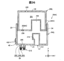
- FIG. 2 is a schematic top view of the carriage unit 60.
- FIG. 3 is a schematic cross-sectional view taken along line F2-F2 of FIG.
- the holder unit 61 (FIGS. 2 and 3) has five wall portions 62, 64, 65, 66, and 67.
- the wall portion 62 is also called the device front wall portion 62
- the wall portion 64 is also called the first side wall portion 64
- the wall portion 65 is also called the second side wall portion 65
- the wall portion 66 is also called the third side wall portion 66.
- 67 is also referred to as a fourth side wall portion 67.
- the five wall portions 62, 64, 65, 66, and 67 are formed of, for example, a synthetic resin.
- the apparatus front wall 62 constitutes the bottom wall of the holder unit 61.
- the apparatus front wall 62 is located on the mounting direction side.
- the four wall portions 64, 65, 66, 67 extend in the + Z-axis direction (removal direction) from the peripheral portion of the device front wall portion 62.
- a recess is formed by these five wall portions 62, 64, 65, 66 and 67.
- This recess forms a cartridge housing chamber 69 (also referred to as “cartridge mounting portion 69”) that houses the cartridge 20.
- the cartridge storage chamber 69 has a plurality of slots (mounting spaces) 69A to 69F that can receive the cartridges 20.
- the plurality of slots 69A to 69F may be divided, for example, by providing a plate-like partition wall on the apparatus front wall 62.
- the first side wall portion 64 and the second side wall portion 65 face each other in the Y-axis direction.
- the third side wall portion 66 and the fourth side wall portion 67 face each other in the X-axis direction.
- the Z-axis direction is the height direction
- the Y-axis direction is the length direction
- the X-axis direction is the width direction.
- the holder unit 61 includes a liquid introduction needle 622 as a liquid introduction portion, an engagement structure 70, and an electrode portion 644 for each of the slots 69A to 69F.
- the liquid introduction needle 622 (FIG. 3) is disposed on the front wall portion 62 of the apparatus.
- the liquid introduction needle 622 protrudes from the device front wall 62 in the + Z axis direction. Inside the liquid introduction needle 622, a flow path through which ink can flow is formed.
- the liquid introduction needle 622 extends along the ⁇ Z axis direction (mounting direction).
- the liquid introduction needle 622 has a proximal end portion 622s located on the apparatus front wall portion 62 side and a distal end portion 622t opposite to the proximal end portion 622s.
- the liquid introduction needle 622 of the present embodiment has a substantially circular cross section and has a central axis CT extending along the mounting direction (+ Z axis direction).
- the direction from the base end 622s to the tip end 622t is the + Z-axis direction, and the direction from the tip end 622t to the base end 622s is the ⁇ Z-axis direction.
- the liquid introduction needle 622 communicates with the head unit 50.
- the engagement structure 70 is a columnar member extending from the device front wall 62 in the removal direction (+ Z axis direction).
- the engagement structure 70 includes a main body portion 772 extending in the removal direction from the device front wall portion 62, and an engagement portion 776 connected to an end portion (removal direction side end portion) of the main body portion 772.
- the engagement structure 70 may be integrally formed with the device front wall portion 62 by synthetic resin, or may be formed by a separate member from the device front wall portion 62.
- the main body 772 is a columnar member. One end 772 s of the main body 772 is connected to the device front wall 62.
- the main body 772 is configured to be movable in a direction RM in which the other end 772t has a Y-axis direction component by elastically deforming the main body 772 with the one end 772s as a fulcrum by an external force.
- the external force applied to the main body 772 is, for example, a force applied by the engagement structure 70 coming into contact with the cartridge 20 in the mounting process of the cartridge 20.
- the engaging portion 776 is a protrusion connected to the other end portion 772 t of the main body portion 772.
- the engaging portion 776 is detached from the other end 772t of the main body 772t (+ Z axis direction) and perpendicular to the removing direction, and is directed from the second side wall 65 to the first side wall 64 (specifically, -Y Project in the axial direction).
- the engaging portion 776 can be engaged with the cartridge 20 (specifically, an engaged portion described later) in a mounted state where the cartridge 20 is mounted on the holder unit 61. Engagement of the engaging portion 776 and the engaged portion of the cartridge 20 restricts movement of the cartridge 20 in the removal direction (+ Z-axis direction) in the mounted state.
- the engaging portion 776 includes a guide surface 775 and an engagement forming surface 774.
- the guide surface 775 contacts the cartridge 20 in the mounting process of the cartridge 20. By this contact, the other end 772t moves to the ⁇ Y axis direction side.
- the guide surface 775 is a member for guiding the cartridge 20 to the engagement position.
- the guide surface 775 faces in a direction including a component in a direction perpendicular to the removal direction ( ⁇ Z axis direction) and the removal direction.
- the guide surface 775 has a direction including a component in a direction ( ⁇ Y axis direction) from the second side wall 65 toward the first side wall 64 perpendicular to the removal direction ( ⁇ Z axis direction) and the removal direction.
- the face (element) faces the direction” is directed to the direction of the normal vector Ve of the face (element). That is, the direction of the normal vector Ve1 of the guide surface 775 is a direction including a + Z-axis direction component and a ⁇ Y-axis direction component.
- the engagement forming surface 774 engages with the engaged portion of the cartridge 20 in the mounted state of the cartridge 20.
- the engagement forming surface 774 is a horizontal surface that faces the mounting direction ( ⁇ Z-axis direction).
- the engagement forming surface 774 extends from the main body portion 772 to the side where the holder side terminal 645 is located ( ⁇ Y axis direction side).
- the engagement forming surface 774 is not limited to the present embodiment as long as the engagement forming surface 774 has a shape that can be engaged with an engaged portion of the cartridge 20 described later in order to restrict movement of the cartridge 20 in the removal direction.
- the engagement forming surface 774 may be inclined with respect to the removal direction, or may be a surface having irregularities instead of a flat surface.
- a shape that can be engaged by being engaged with the engaged portion of the cartridge 20 may be employed.
- the engagement structure 70 may further include a device-side operation unit (not shown) for moving the engagement unit 776 in the direction indicated by the arrow RM.
- the apparatus side operation part is arrange
- the apparatus-side operation unit is used for releasing the engagement between the engagement forming surface 774 and the cartridge 20.
- the device-side operation unit is, for example, a rod-shaped member connected to the other end 772t.
- a part of the apparatus side operation part protrudes outward from the apparatus front wall part 62. The user can move the engaging portion 776 by applying an external force to the apparatus-side operation portion.
- the electrode portion 644 has a plurality of holder side terminals 645.
- the electrode part 644 is provided on the first side wall part 64.
- nine holder side terminals 645 are provided.
- the number of holder side terminals 645 is not limited to this, and may be less than nine or more than nine.
- the holder side terminal 645 is electrically connected to the control unit 38 (FIG. 1).
- a part of the holder side terminal 645 is located in the cartridge housing chamber 69.
- the holder side terminal 645 is a plate-shaped metal member and is configured to be elastically deformable at least in the Y-axis direction.
- each holder-side terminal 645 is electrically connected to the contact portion by contacting a corresponding member (contact portion) of the cartridge 20. In the mounted state, each holder-side terminal 645 urges the cartridge 20 toward the + Y-axis direction side by elastically deforming toward the ⁇ Y-axis direction side.
- each part with which the holder unit 61 is provided has the following positional relationship. That is, the liquid introduction needle 622 and the electrode portion 644 are located on one side RA, and the engaging portion 776 is located on the other side RB.
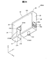
- FIG. 4 is a perspective view of the cartridge 20 of the first embodiment.
- FIG. 5 is a cross-sectional view of the cartridge 20. 4 and 5 are attached with XYZ axes in the mounted state. In the following drawings, XYZ axes in the mounted state are attached as necessary.
- the cartridge 20 (FIG. 4) includes an outer shell 28, a liquid storage unit 201, a liquid supply unit 212, a circuit board 40, and an engaged structure 27.
- the outer shell 28 forms the outer surface of the cartridge 20.
- the outer shell 28 is a main body of the cartridge 20 and defines an internal space including the liquid storage unit 201.
- the outer shell 28 is made of a synthetic resin such as polypropylene (PP).
- PP polypropylene
- the outer shell 28 has a substantially prismatic shape or a substantially rectangular parallelepiped shape. Part of the outer shell 28 may be formed of a resin film.
- the outer shell 28 includes a first wall portion 21, a second wall portion 22, a third wall portion 23, a fourth wall portion 24, a fifth wall portion 25, and a sixth wall portion 26.
- the outer surfaces of the first wall portion 21 to the sixth wall portion 26 are each generally flat.
- the “substantially flat” includes the case where the entire surface is completely flat and the case where the surface is partially uneven. That is, it includes a case where the surface or wall constituting the outer shell 28 of the cartridge 20 can be grasped even if there is some unevenness on a part of the surface.
- the outer shapes of the first wall portion 21 to the sixth wall portion 26 in plan view are all substantially rectangular.
- the first wall portion 21 constitutes a horizontal bottom surface in the mounted state.
- the first wall portion 21 faces a direction having a component in the mounting direction ( ⁇ Z-axis direction).
- the first wall portion 21 faces the mounting direction. That is, in this embodiment, the direction of the normal vector on the outer surface of the first wall portion 21 is the mounting direction.
- the first wall portion 21 is also referred to as a “tip side portion 21”. It can be said that the first wall portion (front end side portion) 21 is a portion located on the mounting direction side of the outer shell 28.
- the first wall portion (front end side portion) 21 is a portion facing the device front wall portion 62 (FIG. 3) where the liquid introduction needle 622 is provided.
- the 1st wall part 21 faced the mounting direction, it is not limited to this, What is necessary is just to face the direction which has a component of a mounting direction.
- the second wall portion 22 constitutes a horizontal upper surface in the mounted state.
- the second wall portion 22 faces the first wall portion 21.
- the second wall portion 22 is located on the removal direction side opposite to the mounting direction.
- the 2nd wall part 22 is a part which faces the direction which has a component of a removal direction (+ Z-axis direction). In the present embodiment, the second wall portion 22 faces the removal direction.
- the second wall portion 22 is also referred to as a “rear end portion 22”.
- “when two elements face each other” means either a case where another element is located between the two elements or a case where no other element is located between the two elements. Including the case.
- An air inlet 220 (FIG. 5) is formed in the second wall portion 22. The air inlet 220 introduces air into the liquid container 201 as the ink in the liquid container 201 is consumed.
- the cartridge 20 may have a liquid injection port for injecting ink into the liquid storage unit 201 on the second wall portion 22 or the like.
- 3rd wall part 23 comprises a back surface in a mounting state.
- the third wall portion 23 intersects the first wall portion 21 and the second wall portion.
- the outer surface of the third wall portion 23 is a surface (XZ plane) parallel to the X-axis direction and the Z-axis direction and perpendicular to the Y-axis direction.
- two elements for example, a wall or a surface
- intersect means that the two elements actually intersect each other and the other element when one element is extended. It means that the state intersects with each other and the state where the extended portions intersect when they extend to each other.
- 4th wall part 24 comprises a front surface in a mounting state.
- the fourth wall portion 24 intersects the first wall portion 21 and the second wall portion 22. Further, the fourth wall portion 24 faces the third wall portion 23.
- the outer surface of the fourth wall portion 24 is a surface (YZ plane) parallel to the X-axis direction and the Z-axis direction and perpendicular to the Y-axis direction.
- the fifth wall 25 constitutes the right side surface in the mounted state.
- the sixth wall portion 26 constitutes the left side surface in the mounted state.
- the fifth wall portion 25 and the sixth wall portion 26 face each other.
- the fifth wall portion 25 and the sixth wall portion 26 intersect with the first to fourth wall portions 21 to 24, respectively.
- the outer surfaces of the fifth wall portion 25 and the sixth wall portion 26 are surfaces (YZ plane) parallel to the Y-axis direction and the Z-axis direction and perpendicular to the X-axis direction.
- the fifth wall portion 25 and the sixth wall portion 26 face each other.
- the outer shell 28 has a dimension in a direction in which the fifth wall portion 25 and the sixth wall portion face each other (X-axis direction), and a direction in which the first wall portion 21 and the second wall portion 22 face each other (Z-axis direction). And the dimension in the direction (Y-axis direction) in which the third wall portion 23 and the fourth wall portion 24 face each other. That is, the distance between the third wall portion 23 and the fourth wall portion 24 is longer than the distance between the fifth wall portion 25 and the sixth wall portion.
- the Y-axis direction orthogonal to the mounting direction is also referred to as the first direction.
- the first direction is a direction in which the third wall portion 23 and the fourth wall portion 24 face each other.
- the first direction is a direction in which the dimension of the outer shell 28 is large among two directions (X-axis direction and Y-axis direction) orthogonal to the mounting direction.
- the center of the outer surface of the third wall portion 23 and the outer surface of the fourth wall portion 24 is the central portion CPb in the first direction, and the third wall is located with respect to the central portion CPb.
- the portion 23 side is one side RA
- the fourth wall portion 24 side is the other side RB with respect to the central portion CPb.
- the liquid storage unit 201 (FIG. 5) stores ink to be supplied to the head unit 50.
- the liquid container 201 is defined by the outer shell 28.
- the liquid supply unit 212 can be connected to the liquid introduction needle 622 (FIG. 3).
- the liquid supply unit 212 communicates with the liquid storage unit 201 through a communication hole 205 formed in the first wall portion 21. That is, the liquid supply unit 212 can supply ink to the printer 10.
- the liquid supply unit 212 is disposed on the first wall portion 21 that constitutes the tip side portion of the outer shell 28. Further, the liquid supply unit 212 is disposed on one side RA in the first direction.
- the liquid supply part 212 is a cylindrical member that protrudes from the first wall part 21 in the mounting direction. The tip of the liquid supply unit 212 is open.
- the liquid supply unit 212 distributes the ink stored in the liquid storage unit 201 to the outside (for example, the liquid introduction needle 622) through the opening at the tip.
- the liquid introduction needle 622 is inserted into the cylindrical liquid supply section 212, whereby the liquid supply section 212 is connected to the liquid introduction needle 622. This connection enables ink to flow from the liquid supply unit 212 to the liquid introduction needle 622.
- a valve mechanism 29 is disposed inside the liquid supply unit 212.
- the valve mechanism 29 opens and closes the internal flow path of the liquid supply unit 212.
- the valve mechanism 29 includes a seal portion (valve seat) 29A, a valve body 29B, and an urging member 29C in order from the distal end side of the liquid supply portion 212.
- the seal portion 29A is a substantially annular member.
- the seal portion 29A is made of an elastic body such as rubber or elastomer, for example.
- the seal portion 29 ⁇ / b> A is press-fitted inside the liquid supply portion 57.
- the valve body 29B is a substantially columnar member.
- the valve body 29 ⁇ / b> B closes the hole (valve hole) formed in the seal portion 29 ⁇ / b> A before the cartridge 20 is attached to the holder unit 61 (non-attached state).
- the urging member 29C is a compression coil spring.
- the urging member 29C urges the valve body 29B in the direction toward the seal portion 29A.
- the liquid introduction needle 622 FIG. 3
- the valve body 29 ⁇ / b> B pushes the valve body 29 ⁇ / b> B in the direction away from the seal portion 29 ⁇ / b> A, whereby the valve body 29 ⁇ / b> B is separated from the seal portion 29 ⁇ / b> A.
- the valve mechanism 29 is opened.
- the circuit board 40 (FIG. 4) is electrically connected to the control unit 38 (FIG. 1) when the cartridge 20 is mounted.
- a plurality of unit-side terminals 432 are provided on the surface 40fa of the circuit board 40.
- a plurality of unit side terminals 432 are provided corresponding to the number of holder side terminals 645 (FIG. 3).
- the outer shape of each unit side terminal 432 is substantially rectangular.
- the unit-side terminal 432 and the holder-side terminal 645 can be electrically connected by the center portion of the substantially rectangular unit-side terminal 432 coming into contact with the corresponding holder-side terminal 645. Therefore, the unit side terminal 432 is also referred to as a contact portion 432.
- An electrical device such as a storage device is provided on the back surface of the circuit board 40. This electrical device is connected to the unit side terminal 432 by wiring.
- the storage device stores information (ink remaining amount and ink color) related to the ink of the cartridge 20. In the mounted state of the cartridge 20, signals are exchanged between the storage device and the control unit 38 (FIG. 1).
- the circuit board 40 (FIG. 5) is disposed on the third wall portion 23 located on one side RA in the first direction (Y-axis direction).
- the direction of the normal vector of the surface 40fa of the circuit board 40 is the ⁇ Y axis direction.
- the unit side terminal 432 is disposed on one side RA in the second direction.
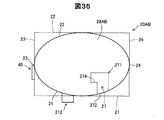
- the engaged structure 27 includes an engaged portion 274, a receiving portion 275, and a first opening 272.
- the engaged structure 27 is a recess formed in the first wall portion 21.
- the engaged structure 27 is defined by an inner wall portion 271 provided in the cartridge 20.
- the receiving portion 275 receives the columnar engagement structure 70 (FIG. 3) in the mounted state.
- the receiving portion 275 includes a first receiving portion 275A that receives the main body portion 772, and a second receiving portion 275B that receives the engaging portion 776.
- the first receiving portion 275A is located closer to the mounting direction than the second receiving portion 275B.
- a step is formed at the boundary between the first receiving portion 275A and the second receiving portion 275B.
- the engaged portion 274 is formed by this step.
- the first opening 272 is an opening formed in the first wall 21. It can be said that the 1st opening part 272 is an opening of the receiving part 275 which is a recessed part. The first opening 272 opens so that the main body 772 of the engagement structure 70 can be inserted.
- the opening direction of the first opening 272 is the mounting direction ( ⁇ Z axis direction).
- the opening direction is the direction of the normal vector Ve2 (FIG. 5) of the opening surface of the first opening 272 from the inside of the cartridge 20 toward the outside.
- the engaged portion 274 can be engaged with an engaging portion 776 (FIG. 3) of the printer 10.
- the engaged portion 274 is formed by an inner wall portion 271 that defines the engaged structure 27.
- the engaged portion 274 is a surface facing the removal direction ( ⁇ Z axis direction).
- the engaged portion 274 extends from one wall portion 278 forming a side wall portion of the receiving portion 275 that is a concave portion to the side where the unit side terminal 432 is located in the first direction ( ⁇ Y axis direction side).
- the wall portion 278 is located on the unit side terminal 432 side ( ⁇ Y-axis direction side) in the first direction in the side wall portion of the first receiving portion 275A.
- the wall 278 defines the first opening 272.
- the engaged portion 274 is disposed inside the outer surface of the outer shell 28. That is, the engaged portion 274 is disposed in a region surrounded by the outer surface of the outer shell 28. Further, the engaged portion 274 is disposed between the first wall portion 21 and the second wall portion 22. Further, the engaged portion 274 is disposed between the third wall portion 23 and the fourth wall portion 24. Further, the engaged portion 274 is disposed between the fifth wall portion 25 and the sixth wall portion 26.
- the configuration of the engaged portion 274 is not limited to the present embodiment, and it is sufficient that the movement of the cartridge 20 in the removal direction can be restricted by engaging with the engaging portion 776.
- the engaging portion 776 may be a protrusion extending in the horizontal direction
- the engaged portion 274 may be a through-hole portion that receives the engaging portion 776 that is a protrusion.
- FIG. 6 is a diagram illustrating a process of attaching the cartridge 20 to the holder unit 61.
- FIG. 7 is a diagram illustrating a mounting state of the cartridge 20 to the holder unit 61.
- the engaging portion 776 is in contact with the first wall portion 21 that defines the first opening 272 and the insertion into the receiving portion 275 is advanced, so that the engaging portion 776 is moved in the + RM direction (fourth).
- the main body 772 is elastically deformed so as to move in the direction in which the wall 24 is located.
- the engaging portion 776 is engaged while the engaging portion 776 (specifically, the end portion on the ⁇ Y-axis direction side of the engaging portion 776) abuts the wall portion 278. Proceed to the back side (+ Z-axis direction side) of the receiving part 275 toward the joint part 274.
- the engaging portion 776 comes into contact with the wall portion 278, the displacement of the engaging portion 776 in the + RM direction is maintained.
- the engaging portion 776 passes through the wall portion 278, the engaging portion 776 and the wall portion 278 are separated from each other, resulting from an external force applied from the wall portion 278 to the engaged portion 274.
- the elastic deformation of the main body 772 is released.
- the engaging portion 776 moves to the ⁇ RM direction side (third wall portion 23 side), and the engaged portion 274 faces the engagement forming surface 774.
- the wall portion 278 also functions as a guide portion for guiding the engaging portion 776 to the engaged portion 274.
- the liquid supply unit 212 is connected to the liquid introduction needle 622, and the unit side terminal 432 contacts the holder side terminal 645. Further, in the mounted state of the cartridge 20, the cartridge 20 receives the external force Pt and the external force Ps from the holder unit 61.
- the external force Pt is a force applied to the valve body 29B of the cartridge 20 by the liquid introduction needle 622.
- the direction of the external force Pt is the removal direction (+ Z-axis direction).
- the external force Ps is a force applied to the unit side terminal 432 of the cartridge 20 by the holder side terminal 645.
- the direction of the external force Ps is a direction (+ Y-axis direction) from the one side RA to the other side RB in the first direction (Y-axis direction).
- the cartridge 20 receives a force in the removal direction by the external force Pt.
- the engaged portion 274 engages with the engagement forming surface 774, thereby restricting the movement of the cartridge 20 in the removal direction.
- the cartridge 20 receives a force in the direction from the third wall portion 23 side to the fourth wall portion 24 side (+ Y-axis direction) by the external force Ps.
- the direction of the external force Ps is the direction (locking direction) opposite to the direction in which the engagement between the engaged portion 274 and the engagement forming surface 774 is released. Therefore, the possibility that the engaged portion 274 is disengaged from the engagement forming surface 774 can be reduced.
- the user When removing the cartridge 20 from the holder unit 61, the user operates the device side operation unit provided in the engagement structure 70 to move the engagement unit 776 in the + RM direction. As a result, the engaged portion 274 is disengaged from the engagement forming surface 774. In this state, the user removes the cartridge 20 from the holder unit 61 by moving the cartridge 20 in the removal direction.
- a lever structure provided on the side surface forming the outer shell of the cartridge is employed as the engaged structure of the cartridge.
- the cartridge and the holder unit may be increased in size by providing the lever structure.
- the lever structure since the lever structure is provided on the side surface, there is a possibility that the lever structure may be damaged if the cartridge is accidentally dropped.
- the printing operation of the printer is executed in a state where the cartridge is not sufficiently mounted on the holder unit.
- the lever structure is provided on the side surface, and therefore the other side surface of the cartridge not provided with the lever structure is inclined in the mounting state.
- Another example of a state where the mounting is insufficient is a state where the holder unit and the lever structure are not engaged due to deformation of the lever structure or adhesion of foreign matter.
- at least one of the problems that can occur in the conventional technology can be solved.
- the engaged portion 274 is formed inside the outer surface of the outer shell 28 as shown in FIG. Thereby, the possibility that foreign matters such as dust adhere to the engaged portion 274 and its surroundings can be reduced. As a result, the engaged portion 274 and the engaging portion 776 can be engaged with each other with high accuracy, so that the reliability related to the mounting of the cartridge 20 can be improved.
- the engaged portion 274 (the engagement position st with the engaging portion 776 shown in FIG. 7) is formed on the inner side of the outer surface of the outer shell 28. Therefore, the cartridge 20 can be downsized as compared with the case where the engaged portion 274 is formed outside the outer surface of the outer shell 28.
- the engaged portion 274 is formed by the receiving portion 275 that is a recess that can be engaged with the engaging portion 776 that is a protrusion.
- the engaged portion 274 can be formed with a simple structure.
- the engaged portion 274 may have another configuration as long as it can be engaged with the engaging portion 776 that is a protrusion.
- the engaged portion 274 may be formed by providing a plate-like wall extending in the mounting direction in the inner wall portion 271 and forming an opening penetrating in the Y-axis direction on the plate-like wall. Even in this case, the engaged portion 274 can be formed with a simple structure.
- the engaged portion 274 is not limited to a horizontal surface facing the removal direction, and may be inclined with respect to the removal direction, for example, as long as the engagement portion 274 can be engaged with the engagement portion 776.
- A-5-1 Deformation modes of the number, position, and shape of the engaging structure 70 and the engaged structure 27:
- the number, position, and shape of the engagement structure 70 are not limited to the above embodiment. The following describes how the number and position of the engagement structures 70 are modified.
- FIG. 8 is a schematic diagram for explaining the first modified embodiment.
- FIG. 8 is a view of the cartridge 20A and the engagement structure 70 as viewed from the + X-axis direction side.
- the engaged structure 27 and the engaging structure 70 located on the ⁇ X axis direction side of the sixth wall portion 26 are also shown.
- the difference between the cartridge 20A and the cartridge 20 (FIG. 5) of the first embodiment is the position of the engaged structure 27 in the Y-axis direction.
- the position of the engaging structure 70 is also different from the position of the engaging structure 70 of the first embodiment. Since the configuration of the other liquid ejecting system is the same as that of the first embodiment, the same reference numeral as that of the first embodiment is assigned to the same configuration, and the description thereof is omitted as appropriate.
- the engaged structure 27 of the cartridge 20 ⁇ / b> A has a liquid supply portion 212 and a contact portion when the cartridge 20 ⁇ / b> A is viewed in a predetermined direction (+ Z axis direction, removal direction) from the first wall portion 21 toward the second wall portion 22. 432. That is, when the cartridge 20 ⁇ / b> A is planarly viewed in a predetermined direction, the opening 272 and the engaged portion 274 (the engagement position st between the engaged portion 274 and the engaging portion 776) are in contact with the liquid supply portion 212. It is located between the part 432.
- the liquid supply unit 212 is located closer to the third wall 23 than the fourth wall 24 when the cartridge 20A is viewed in plan in a predetermined direction. That is, in the first direction, the liquid supply unit 212 is located on one side RA.
- the same effect as that of the first embodiment is obtained in that it has the same configuration as that of the first embodiment. Furthermore, according to the first modification, the engagement position st is set on one side RA of the cartridge 20 as compared with the case where the engagement position st is not positioned between the liquid supply unit 212 and the contact unit 432 in the first direction. It is possible to reduce the possibility that one of the two sides sandwiching the side is inclined. Thereby, compared with the case where engagement position st is not located between the liquid supply part 212 and the contact part 432 in a 1st direction, the contact with the contact part 432 and the electrode part 644 can be maintained favorable.
- the possibility that one of the both sides sandwiching the engagement position st can be reduced, so that the connection between the liquid supply unit 212 and the liquid introduction needle 622 can be maintained well.
- the reliability related to the mounting of the cartridge 20A can be further improved.
- FIG. 9 is a schematic diagram for explaining the second modified embodiment.
- FIG. 9 is a view of the cartridge 20B and the engagement structure 70B as seen from the + X-axis direction side. Further, for easy understanding, the engaged structure 27 and the engaging structure 70B, which are located on the ⁇ X axis direction side of the sixth wall portion 26, are also illustrated.
- the difference between the first modified embodiment and the second modified embodiment is the configuration of the main body 772B. Since the other configuration is the same as that of the first modified embodiment, the same reference numeral as that of the first modified embodiment is assigned to the same configuration and the description thereof is omitted.
- the engaging structure 70B has a positioning portion 790 for positioning in a direction orthogonal to the mounting direction of the cartridge 20B with respect to the holder unit 61.
- the positioning portion 790 is a portion on the one end portion 772s side of the main body portion 772B.
- a cross section (transverse cross section) orthogonal to the mounting direction of the positioning portion 790 is an outer shape that can be inserted into the opening 272 and forms an outer shape that causes a slight gap from the contour of the opening 272. In the mounted state, the positioning portion 790 is inserted through the opening 272.
- the cross-section of the other end 772t of the main end 772B forms an outer shape that produces a sufficient gap with the contour of the opening 272.
- the positioning in the direction perpendicular to the mounting direction of the cartridge 20B can be performed by inserting the positioning portion 790 into the opening 272 in the mounting process of the cartridge 20B.
- the opening part 272 of the positioning part 790 is entered.
- the insertion of is started.
- the positioning of the liquid supply part 212 with respect to the liquid introduction needle 622 and the positioning of the contact part 432 with respect to the holder side terminal 645 in the direction orthogonal to the mounting direction can be performed with higher accuracy.
- the reliability related to mounting on the cartridge 20B can be further improved.
- the positioning unit 790 is configured to perform positioning in two directions (X-axis direction and Y-axis direction) orthogonal to the mounting direction, but in one direction (X-axis) orthogonal to the mounting direction.
- Direction and one direction of the Y-axis direction) may be configured.
- the positioning unit 790 performs positioning in the Y-axis direction, it is only necessary that the dimension of the positioning unit 790 is slightly smaller than the dimension of the opening 272 at least in the Y-axis direction.
- FIG. 10 is a schematic diagram for explaining the third modification.
- FIG. 10 is a view of the cartridge 20C and the engagement structure 70 as seen from the + X-axis direction side, as in FIG.
- the engaged structure 27 and the engaging structure 70 located on the ⁇ X axis direction side of the sixth wall portion 26 are also shown.
- the difference between the cartridge 20 ⁇ / b> C and the cartridge 20 (FIG. 5) of the first embodiment is the number of engaged structures 27.
- the same number of engaging structures 70 as the number of engaged structures 27 are provided in the holder unit 61. Since the configuration of the other liquid ejecting system 1000 is the same as that of the first embodiment, the same components are denoted by the same reference numerals and description thereof is omitted as appropriate.
- the cartridge 20C is provided with two engaged structures 27.
- One engaged structure 27 is formed between the liquid supply part 212 and the contact part 432 when the cartridge 20C is viewed in a predetermined direction (+ Z-axis direction), similarly to the first modified embodiment (FIG. 8).
- the other engaged structure 27 Located in.
- the other engaged structure 27 has the fourth wall portion 24 rather than the liquid supply portion 212 when the cartridge 20C is viewed in a predetermined direction (+ Z-axis direction).
- the two engaged structures 27 sandwich the liquid supply unit 212 in the first direction (Y-axis direction).
- the same effect is achieved in that it has the same configuration as the first embodiment and each modified aspect. Furthermore, according to the third modified embodiment, since the cartridge 20C has the plurality of engaged structures 27, the possibility that the cartridge 20C moves in the removal direction in the mounted state can be further reduced. Further, according to the third modification, the two engaged structures 27 are arranged so as to sandwich the liquid supply unit 212 in the first direction (Y-axis direction). Thereby, the external force in the removal direction received by the cartridge 20C from the liquid introduction needle 622 can be received by the two engaged portions 274 in a distributed manner. Therefore, the connection between the liquid supply unit 212 and the liquid introduction needle 622 can be favorably maintained. As described above, according to the third modification, the reliability related to mounting on the cartridge 20C can be further improved.
- the operation unit for releasing the engagement between the engaged portion 274 and the engaging portion 776 is provided on the printer 10 side, but is not limited thereto.
- the operation unit may be provided on the cartridge 20 side. Below, the deformation
- FIG. 11 is a schematic diagram for explaining a first modification of the operation unit.
- FIG. 11 is a view of the cartridge 20D and the engagement structure 70D as seen from the + X-axis direction side, as in FIG.
- the engaged structure 27D and the engaging structure 70D which are located on the ⁇ X axis direction side of the sixth wall portion 26, are also illustrated.
- the difference between the cartridge 20D and the cartridge 20 of the first embodiment (FIG. 5) is that the engaged structure 27D has a unit side operation member 79, and the first direction (Y Position in the axial direction). Since the configuration of the other liquid ejecting system 1000 is the same as that of the first embodiment, the same components are denoted by the same reference numerals and description thereof is omitted as appropriate.
- the opening 272 and the engagement position st in the first direction (Y-axis direction) are located between the liquid supply unit 212 and the contact unit 432, as in the cartridge 20A (FIG. 8) of the first modification.
- the engagement structure 70 ⁇ / b> D has a facing portion 778 connected to the guide surface 775 and the engagement forming surface 774.
- the facing portion 778 is a plane that faces the direction toward one side RA in the first direction (Y-axis direction).
- the engaged structure 27D newly has a unit side operation member 79.
- the unit side operation member 79 is inserted through the through hole 232 from the third wall portion 23 to the second receiving portion 275B.
- the unit side operation member 79 is a columnar member extending in the first direction (Y-axis direction).
- the unit side operation member 79 is inserted into the through hole 232 so as to be movable along the first direction in the through hole 232.
- One end portion (unit side operation portion) 798 of the unit side operation member 79 is disposed outside the outer shell 28 (first to sixth wall portions 21 to 26) in the mounted state. In this modification, the one end 798 protrudes outward from the third wall portion 23.
- the one end 798 is operated to release the engagement between the engaged portion 274 and the engaging portion 776. Therefore, the one end 798 is also referred to as a unit side operation unit 798.
- the other end portion (engagement release portion) 799 of the unit side operation member 79 faces the facing portion 778 of the engagement portion 776D in the mounted state.
- the engagement release portion 799 moves the engagement portion 776D in the release direction (+ Y-axis direction) by contacting the engagement portion 776D.
- the unit side operation member 79 is disposed at a position closer to the rear end side portion 22 than the front end side portion 21 in the outer shell 28. Release of engagement between the engaged portion 274 and the engaging portion 776D is performed by the user moving the unit side operation portion 798 in the direction toward the facing portion 778 (+ Y-axis direction), thereby releasing the engagement releasing portion 799. Is brought into contact with the engaging portion 776D to move the engaging portion 776D to the + Y-axis direction side (release direction side). Thereby, the engagement between the engaged portion 274 and the engaging portion 776D is released.
- the engaged structure 27D includes the unit-side operation unit 798, so that the user operates the unit-side operation unit 798 so that the engaged unit 274 and the engagement unit 776D are operated. Can be easily released.
- the unit side operation portion 798 is disposed at a position closer to the rear end side portion 22 than to the front end side portion 21. Thereby, the user can operate the unit side operation part more easily.
- the unit side operation member 79 moves in a direction (first direction) orthogonal to the mounting direction. Thereby, the engaging portion 776D can be easily moved in the direction for releasing the engagement (+ Y-axis direction).
- FIG. 12 is a schematic diagram for explaining a second modification of the operation unit.
- the difference between the carriage unit 60E and the carriage unit 60 (FIG. 3) of the first embodiment is that, in the carriage unit 60E, the engaging portion 776 of the engaging structure 70 and the engaged portion 274 of the cartridge 20 (FIG. 5). ) Is disposed on the apparatus front wall 62E. Since the configuration of the other liquid ejecting system is the same as that of the first embodiment, the same components are denoted by the same reference numerals and description thereof is omitted as appropriate.
- the apparatus front wall portion 62E includes a fixed wall portion 62E1 and a moving wall portion 62E2.
- the moving wall 62E2 is configured to be movable in the Y-axis direction with respect to the fixed wall 62E1.
- a rail 780 extending along the Y-axis direction is disposed on the fixed wall portion 62E1
- the moving wall portion 62E2 has a convex portion disposed in the rail 780.
- the moving wall 62E2 can move in the Y-axis direction with respect to the fixed wall 62.
- a liquid introduction needle 622 is disposed on the fixed wall portion 62E1.
- An engagement structure 70 is disposed on the moving wall portion 62E2.
- the engaging portion 776 In the mounted state, the engaging portion 776 is moved in the + Y-axis direction by moving the moving wall 62E2 in the + Y-axis direction. As a result, the engagement between the engaging portion 776 and the engaged portion 274 (FIG. 5) is released.
- the moving wall portion 62E2 and the other wall portion (for example, the second side wall portion 65) interlocking with the moving wall portion 62E2 function as the apparatus-side operation portion.
- the user grasps the second side wall portion 65 and moves it in the + Y-axis direction, thereby moving the engaging portion 776 in the + Y-axis direction and engaging the engaged portion 274 and the engaging portion 776. Is released. Thereby, the engagement between the engaged portion 274 and the engaging portion 776 can be easily released.
- FIG. 13 is a schematic diagram for explaining a third modification of the operation unit.
- the difference between the cartridge 20F and the cartridge 20 (FIG. 5) of the first embodiment is the configuration of the engaged structure 27F, the fourth wall portion 24F, and the engaging structure 70F. Since the configuration of the other liquid ejecting system is the same as that of the first embodiment, the same components are denoted by the same reference numerals and description thereof is omitted as appropriate.
- the engaged portion 274F of the engaged structure 27F is a surface extending in the + Y-axis direction from the wall portion 277 facing the wall portion 278 among the side wall portions of the first receiving portion 275A. Similarly to the first embodiment, the engaged portion 274F is a surface that faces the removal direction ( ⁇ Z-axis direction).
- the engaging portion 776F of the engaging structure 70F has a portion protruding from the main body portion 772 in the + Y-axis direction. That is, the engagement structure 70F has a configuration obtained by rotating the engagement structure 70F (FIG. 3) of the first embodiment by 180 degrees around the Z-axis direction.
- the fourth wall portion 24F is configured such that the other end portion 24t positioned on the mounting direction side of the fourth wall portion 24F is rotatable with the one end portion 24s positioned on the removal direction side of the fourth wall portion 24F serving as a fulcrum RtF. Supported by the portion 22.
- the other end 24t rotates and moves in a plane parallel to the Y-axis direction and the Z-axis direction as indicated by an arrow RM24.
- the fulcrum RtF is formed by a hinge, for example.
- the unit side operation unit 79F is connected to the one end 24s.
- the unit side operation part 79F protrudes outward from the one end part 24s.
- the engaged portion 274F is connected to the fourth wall portion 24F. Thereby, the unit side operation part 79F is operated, and the other end part 24t side moves centering on the fulcrum RtF.
- the engaged portion 274F also moves in conjunction with the movement on the other end 24t side. By moving the other end 24t outward as indicated by an arrow RM24A, the engaged portion 274F also moves outward (+ Y-axis direction). As a result, the engagement between the engaged portion 274F and the engaging portion 776F is released.
- the fourth wall portion 24F which is a part of the outer shell 28F, is configured to be movable by operating the unit side operation portion 79F. Further, the engaged portion 274F is connected to the fourth wall portion 24F so as to be interlocked with the fourth wall portion 24F. Thereby, since the engaged portion 274F can be easily moved, the engagement between the engaged portion 274F and the engaging portion 776F can be easily released by the movement of the engaged portion 274F.
- FIG. 14 is a schematic diagram for explaining a fourth modification of the operation unit.
- the engagement position st and the opening 272 are arranged between the liquid supply part 212 and the contact part 432 in the first direction (Y-axis direction), similarly to the first modification (FIG. 8).
- FIG. 14 shows a view corresponding to a sectional view taken along line F2-F2 in the mounted state of the cartridge 20G, but the outer shell 28G and the liquid supply unit 212 of the cartridge 20G are schematically shown.
- the difference between the cartridge 20G and the cartridge 20 (FIG. 5) of the first embodiment is the configuration of the engaged structure 27G and the configuration of the engaging structure 70F.
- a through hole (not shown) for inserting an engaged member 80 described later is formed.
- the seventh modification and the first embodiment are different in the configuration of the engagement structure 70G. Since the configuration of the other liquid ejecting system 1000 is the same as that of the first embodiment, the same components are denoted by the same reference numerals and description thereof is omitted as appropriate.
- the engaging structure 70G is formed by a columnar member (main body portion 772G) extending from the device front wall portion 62 in the removal direction (+ Z-axis direction).
- the main body 772G is disposed in a receiving portion 275G that is a recess formed in the first wall 21 in the mounted state.
- the engaging structure 70G has an engaging portion 774G.
- the engaging portion 774G is an opening that is located in the middle of the main body portion 772G and penetrates the main body portion 772G in the Y-axis direction.
- the engaging portion 774G may be a concave portion that is located in the middle of the main body portion 772G and formed on the side surface of the main body portion 772G.
- the engaging portion 774G as a recess receives an engaged portion 274G described later.
- the engaged structure 27G includes a first opening 272, a receiving portion 275G formed inside the outer shell 28G, an engaged member 80, and a biasing member 89.
- the receiving portion 275G is a recess formed in the first wall portion 21.
- a first opening 272 is formed on the side of the recess that faces the bottom surface 280.
- a part including the engaged part 274G of the engaged member 80 and an urging member 89 are arranged.
- the engaged member 80 is connected to the first member 83 inserted through the third wall portion 23, the second member 84 having one end connected to the first member 83, and the other end of the second member 84. And a third member 86.
- the first member 83 is a columnar member extending in the first direction (Y-axis direction).
- One end 83s of the first member 83 is disposed outside the outer shell 28 (first to sixth wall portions 21 to 26) in the mounted state. In this modification, the one end 83s protrudes outward from the third wall 23G.
- the one end portion 83s functions as a unit side operation portion for releasing the engagement between the engaged portion 274G and the engaging portion 774G. Therefore, the one end portion 83s is also referred to as a unit side operation portion 83s.
- the other end 83t of the first member 83 is disposed in the receiving portion 275G.
- the second member 84 is a columnar member extending from the other end 83t of the first member 83 in the mounting direction ( ⁇ Z axis direction).
- the second member 84 is disposed in the receiving portion 275G.
- the biasing member 89 is a compression coil spring.
- One end portion of the urging member 89 is disposed on the wall portion 277 facing the second member 84 among the side wall portions forming the receiving portion 275G.
- the other end of the urging member 89 is disposed on the second member 84.
- the urging member 89 urges the engaged member 80 in a direction ( ⁇ Y axis direction) from the fourth wall portion 24 toward the third wall portion 23G.
- the ⁇ Y-axis direction is the direction (locking direction) opposite to the direction in which the engagement between the engaged portion 274G and the engaging portion 774G is released.
- the third member 86 is a member connected to the end portion (the other end portion) on the mounting direction side of the second member 84.
- the third member 86 includes an engagement guide portion 866 and an engaged portion 274G.
- the engaged portion 274G is formed by a protrusion (a part of the third member 86) protruding from the second member 84 in the ⁇ Y-axis direction.
- the engaged portion 274G is a surface facing the removal direction.
- the engagement guide portion 866 guides the engagement portion 774G to the engaged portion 274G in the mounting process of the cartridge 20G.
- the engagement guide portion 866 is a surface facing a direction having a mounting direction ( ⁇ Z-axis direction) component and one side RA direction ( ⁇ Y-axis direction) component in the first direction.
- the engagement guide portion 866 moves in the mounting direction ( ⁇ Z-axis direction) while being in contact with the end portion (one end portion) located on the removal direction side of the main body portion 772G.
- the engaged member 80 receives an external force having a + Y-axis direction component from one end of the main body 772G.
- the engaged member 80 moves in the + Y-axis direction against the urging force of the urging member 89. Further, by moving the cartridge 20G in the mounting direction, the engaged portion 274G reaches the engaging portion 774G. When the engaged portion 274G reaches the engaging portion 774G, the engaged member 80 moves in the ⁇ Y-axis direction by the urging force FG of the urging member 89. Thereby, as shown in FIG. 14, the to-be-engaged part 274G and the engaging part 774G engage.
- the user moves the unit side operation portion 83s in the + Y-axis direction against the urging force of the urging member 89.
- the engaged portion 274G moves in the + Y-axis direction, which is the disengagement direction, and the engagement between the engaged portion 274G and the engaging portion 774G is released.
- the same effect is achieved in that the configuration is the same as that of the first embodiment and each of the modifications.
- the engaging portion 774G is formed by a protrusion (third member 86) that can engage with the engaging portion 774G that is an opening.
- the engaged portion 274G can be formed with a simple structure.
- the urging force FG of the urging member 89 to the engaged member 80 releases the engagement between the engaged portion 274G and the engaging portion 774G. This is a force for moving the engaged portion 274G in a direction opposite to the direction ( ⁇ Y-axis direction, lock direction).
- the engaged portion 274G is configured to be movable by contacting the engaging structure 70G. Thereby, the engaged portion 274G can be easily moved. Therefore, the operability of mounting the cartridge 20G on the holder unit 61 can be improved.
- FIG. 15 is a schematic diagram for explaining a fifth modification of the operation unit.
- the engagement position st and the opening 272 are arranged between the liquid supply part 212 and the contact part 432 in the first direction (Y-axis direction), similarly to the first modification (FIG. 8).
- FIG. 15 shows a view corresponding to the F2-F2 cross-sectional view (FIGS. 2 and 3) in the mounted state of the cartridge 20H, but the outer shell 28H and the liquid supply unit 212 of the cartridge 20H are schematically shown. .
- the difference between the cartridge 20H and the cartridge 20G (FIG.
- the seventh modified embodiment is that the engaged member 80 for engaging and releasing the engaged members 80 and 80H and the engaging portion 774G. , 80H is different.
- the engaged portion 274H included in the engaged member 80H according to this modification is rotationally moved around the fulcrum RP to release the engagement with the engaging portion 774G. Since the configuration of the other liquid ejecting system 1000 is the same as that of the fourth modification of the operation unit, the same components are denoted by the same reference numerals and description thereof is omitted as appropriate.
- the engaged structure 27H includes a first opening 272, a receiving portion 275H formed inside the outer shell 28H, an engaged member 80H, and an urging member 89.
- the receiving portion 275H is a recess formed in the first wall portion 21.
- a first opening 272 is formed on the side of the recess that faces the bottom surface 280.
- a portion including the engaged portion 274H of the engaged member 80H and the urging member 89 are disposed.
- the engaged member 80 includes a first member 83H, a second member 84H connected to one end of the first member 83H, and a third member 86H connected to the other end of the second member 84H. .
- the first member 83H is a substantially rectangular parallelepiped member.
- the first member 83H is disposed in an opening formed across the third wall portion 23H and the second wall portion 22H in the outer shell 28H. This opening is connected to the receiving portion 275H.
- One end side corner portion 83Hs of the first member 83H is disposed outside the outer shell 28H.
- the one end side corner portion 83Hs of the first member 83H protrudes outward from the second wall portion 22H and the third wall portion 23H. It can be said that the one end side corner portion 83Hs of the first member 83H is disposed across the second wall portion 22H and the third wall portion 23H.
- the one end side corner portion 83Hs functions as a unit side operation portion for releasing the engagement between the engaged portion 274H and the engaging portion 774G. Therefore, the one end side corner portion 83Hs is also referred to as a unit side operation portion 83Hs.
- the other end side corner portion 83Ht that is a diagonal position of the unit side operation portion 83Hs is disposed in the receiving portion 275H.
- the biasing member 89 is a compression coil spring.
- the urging member 89 applies an urging force FH toward the ⁇ Y axis direction with respect to the first member 83H.
- This urging force FH is a force for moving the engaged portion 274H in the direction opposite to the direction in which the engagement between the engaged portion 274H and the engaging portion 774G is released (+ Y-axis direction, locking direction). It is. Thereby, in a mounting state, possibility that engagement with the to-be-engaged part 274H and the engaging part 774G will be cancelled
- the second member 84H is a columnar member extending in the mounting direction ( ⁇ Z axis direction) from the other end side corner portion 83Ht of the first member 83H.
- the second member 84H is disposed in the receiving portion 275H.
- the second member 84H is rotatably supported by wall portions on both sides in the X axis direction of the receiving portion 275H by a shaft forming member such as a pin. Thereby, the second member 84H forms a fulcrum RP for the engaged member 80H to rotate in a plane parallel to the Y-axis direction and the Z-axis direction.
- 3rd member 86H is the structure which rotated the 3rd member 86 (FIG. 14) of the 4th deformation
- the engagement guide part 866H and the engaged part 274H respectively correspond to the engagement guide part 866 and the engaged part 274G (FIG. 14) of the fourth modification.
- the user moves the unit side operation portion 83Hs in the direction of the arrow RT against the urging force of the urging member 89.
- the engaged portion 274H rotates around the fulcrum RP in the engagement releasing direction (arrow RV), and the engagement between the engaged portion 274H and the engaging portion 774G is released.
- the same effect is obtained in that the configuration is the same as that of the first embodiment and each modification. Furthermore, according to this modification, the engaged portion 274H and the engaging portion 774G can be easily released by operating the unit side operation portion 83Hs.
- the unit side operation parts 83s and 83Hs are connected to the tip side part 21 and the tip side part 21 of the outer shells 28G and 28H. It is preferable that they are arranged on the rear end side portions 22 and 22H that face each other and are located on the removal direction side. By doing so, the user can more easily operate the unit side operation units 83s and 83Hs.
- FIG. 16 is a schematic diagram for explaining a sixth modification of the operation unit.
- the difference from the fifth modification of the operation unit is the position of the biasing member 89I.
- symbol is attached
- the engaged member 80I includes an urging member 89I.
- the biasing member 89I is a compression coil spring. One end of the biasing member 89I is disposed on the bottom surface 280 of the receiving portion 275H.
- the engaging structure 70G is urged in the mounting direction ( ⁇ Z axis direction). That is, in the mounted state of the cartridge 20I, the cartridge 20I receives an external force in the removal direction (+ Z axis direction) from the engagement structure 70G as a reaction force of the urging member 89I.
- the cartridge 20I has the urging member 89I that urges the outer shell 28H in the removal direction (+ Z-axis direction) in the mounted state. Accordingly, when the unit-side operation portion 83Hs is rotated in the direction of the arrow Rt and the engagement between the engaged portion 274H and the engaging portion 774G is released, the outer shell 28H is moved by the biasing force of the biasing member 89I. Move in the direction of removal. Thereby, the operability at the time of removing the cartridge 20I from the holder unit 61 can be improved.
- the contact part 432 and the member (seal part 29A) arranged in the liquid supply part 212 are in contact with corresponding parts (the holder side terminal 645 and the liquid introduction needle 622) of the holder unit 61, respectively. Therefore, when the outer shell 28H moves along the mounting direction, a frictional force is generated in the contacted portion.
- the urging member 89I is disposed between the contact part 432 and the liquid supply part 212 in the first direction (Y-axis direction).
- the outer shell 28H can be reliably moved in the removal direction by the biasing force of the biasing member 89I against the frictional force generated when the outer shell 28H moves in the removal direction.
- the engaged portion 274 is a surface that faces the removal direction ( ⁇ Z-axis direction) (FIG. 5), but is not limited to this and is engaged with the engagement portion 776. Any other configuration may be used as long as it can regulate the movement of the cartridge 20 in the removal direction.
- FIG. 17 is a view for explaining a modification of the engaged portion 274J.
- the difference between the modified cartridge 20 shown in FIG. 17 and the modified cartridge 20A shown in FIG. 8 is the shape of the engaged portion 274J. Since the configuration of the liquid ejecting system 1000 having other configurations is the same as that of the modification shown in FIG. 8, the same components are denoted by the same reference numerals and description thereof is omitted as appropriate.
- the engaged portion 274J has a function of releasing the engagement with the engaging portion 776 in addition to the function of engaging with the engaging portion 776.
- the engaged portion 274J is a hemispherical member provided on the wall portion 278 of the receiving portion 275.
- the engaging portion 776 abuts on the spherical surface constituting the outer surface of the engaged portion 274J.
- the removal direction side end part of the engagement structure 70 moves in the engagement release direction (+ Y-axis direction).
- the engagement forming surface 774 reaches the removal direction side end portion 274Jt of the engaged portion 274J.
- the engagement formation surface 774 engages with the removal direction side end portion 274 of the engaged portion 274J.
- the direction of the normal vector of the removal direction side end portion 274Jt is the removal direction (+ Z-axis direction).
- the cartridge 20J When removing the cartridge 20J from the holder unit 61, the cartridge 20J is moved in the removal direction (+ Z-axis direction). As a result, the engaging portion 776 abuts on the spherical surface forming the outer surface of the engaged portion 274J, thereby moving in the disengaging direction (+ Y-axis direction). As a result, the engagement between the engagement forming surface 774 and the removal direction side end portion 274Jt is released.
- the same effect as that of the first embodiment can be obtained in that it has the same configuration as that of the first embodiment and each of the modifications. Furthermore, according to this modification, the engagement between the engaged portion 274J and the engaging portion 776 can be released by a member different from the engaged portion 274J.
- the unit side operation sections 798, 79F, 83s, and 83Hs (FIGS. 11, 13, 14, and 15) described in the above-described modified modes are the holder units in the mounted state of the cartridges 20D, 20F, 20G, and 20H. It is preferable to be disposed at a position exposed from 61. By doing so, the user can easily operate the unit side operation units 798, 79F, 83s, 83Hs.
- FIG. 18 is a perspective view showing a configuration of a liquid ejection system 1000a as the second embodiment of the present invention.
- the difference between the liquid ejecting system 1000a and the liquid ejecting system 1000 (FIG. 1) is that the liquid ejecting system 1000a is an off-carriage type printer 10a and the configuration of the cartridge 20a.
- the mounting direction and the detaching direction of the cartridge 20a are horizontal directions, and in this embodiment, are directions along the Y-axis direction. Since other configurations are the same as those in the first embodiment, the same configurations are denoted by the same reference numerals as those in the first embodiment and description thereof will be omitted as appropriate.
- the printer 10a is provided with the flexible cable 37 (FIG. 1) similarly to 1st Embodiment.
- the printer 10a has a tube 39 for distributing ink contained in the cartridge 20a to the head unit 50. Ink is supplied to the head unit 50 by sucking ink in the cartridge 20a by a pump mechanism (not shown) of the printer 10a.
- the holder unit 61a is configured to be able to mount four cartridges 20a.
- the mounting direction of the cartridge 20a is the -Y axis direction
- the removal direction of the cartridge 20a is the + Y axis direction.
- the first direction is the Z-axis direction
- one side RA is the ⁇ Z-axis direction side
- the other side RB is the + Z-axis direction side.
- FIG. 19 is a diagram for explaining the holder unit 61a.
- the holder unit 61a has five wall portions 62a, 64a, 65a, 66a, 67a (FIGS. 18 and 19).
- the five wall portions 62a, 64a, 65a, 66a, and 67a correspond to the five wall portions 62, 64, 65, 66, and 67 in the first embodiment. That is, the wall 62a is positioned on the mounting direction ( ⁇ Z axis direction) side.
- the wall part 64a comprises the bottom wall of the holder unit 61a.
- the four wall portions 64a, 65a, 66a, 67a extend in the + Y-axis direction (removal direction) from the peripheral portion of the wall portion 62a.
- a concave cartridge housing chamber 69 is formed by the five walls 62a, 64a, 65a, 66a, 67a.
- the cartridge storage chamber 69 is divided into a plurality of slots (mounting spaces) that can receive the cartridges 20a.
- the wall 62a is also called the apparatus front wall 62a
- the wall 64a is also called the first side wall 64a
- the wall 65a is also called the second side wall 65a
- the wall 66a is also called the third side wall 66a.
- 67a is also referred to as a fourth side wall portion 67a.
- the holder unit 61a includes a liquid introduction needle 622, an engagement structure 120, and an electrode portion 644 for each slot.
- the protruding direction of the liquid introduction needle 622 is the + Y-axis direction from the wall 62a.
- the direction in which the central axis CT of the liquid introduction needle 622 extends is the Y-axis direction.
- the electrode portion 644 is provided on the second side wall portion 65a constituting the upper wall.
- the holder-side terminal 645 of the electrode portion 644 biases the cartridge 20a toward the ⁇ Z axis direction side in the mounted state of the cartridge 20a.
- the holder unit 61a may be disposed around the liquid introduction needle 622, and an urging member (for example, a coil spring) for urging the cartridge 20a in the removal direction in the mounted state of the cartridge 20a may be disposed. By doing so, it is possible to reduce the possibility that the second engaged portion 642a and the second engaging portion of the cartridge 20a, which will be described later, are unintentionally released.
- an urging member for example, a coil spring
- the engagement structure 120 is a plate-like member extending in the removal direction (+ Y-axis direction) from the device front wall portion 62a.
- the engagement structure 120 includes a main body portion 122 extending in the removal direction from the device front wall portion 62a, and an engagement portion 124 connected to an end portion (removal direction side end portion) of the main body portion 122.
- the engagement structure 120 may be integrally formed with the device front wall portion 62a with synthetic resin, or may be formed with a separate member from the device front wall portion 62.
- One end portion 122s of the main body portion 122 is connected to the device front wall portion 62a.
- the main body 122 is elastically deformed by an external force so that the other end 122t can move in a direction RP having a Z-axis direction component with the one end 122s as a fulcrum.
- the external force applied to the main body 122 is, for example, a force applied by the engagement structure 120 coming into contact with the cartridge 20a in the mounting process of the cartridge 20a.
- the engaging part 124 is a protrusion connected to the other end part 122 t of the main body part 122.
- the engaging portion 124 is orthogonal to the removal direction (+ Z axis direction) from the other end portion 122t of the main body portion 122, and protrudes in the direction (+ Z axis direction) from the first side wall portion 64a toward the second side wall portion 65a.
- the engaging portion 124 can be engaged with the cartridge 20a (specifically, an engaged portion described later) in a mounted state where the cartridge 20a is mounted on the holder unit 61a. Engagement of the engaging portion 124 and the engaged portion of the cartridge 20a restricts the movement of the cartridge 20a in the mounted state in the removal direction (+ Y-axis direction).
- FIG. 20 is a perspective view of the cartridge 20a.
- FIG. 21 is a schematic diagram for mainly explaining the internal configuration of the cartridge 20a.
- the cartridge 20a (FIG. 20) includes an outer shell 28a, an engaged structure 27a, a liquid storage unit 201a, a circuit board 40, a liquid supply unit 212a, and a unit side operation structure 310.
- the liquid container 201a is a bag housed in the outer shell 28a. This bag is filled with ink.
- the outer shell 28a (FIG. 20) forms an outer surface of a substantially prismatic shape or a substantially rectangular parallelepiped shape.
- the outer shell 28a has first to sixth wall portions 21a to 26a as in the first embodiment.
- the first to sixth wall portions 21a to 26a correspond to the first to sixth wall portions 21 to 26 (FIG. 4) in the first embodiment. That is, the first wall portion 21a constitutes the tip side portion of the cartridge 20a.
- the first wall portion 21a faces the mounting direction ( ⁇ Y-axis direction).
- the second wall portion 22a faces the first wall portion 21a and is located on the removal direction (+ Y axis direction) side.
- the third wall portion 23a is located on one side RA ( ⁇ Z axis direction side) in the first direction (Z axis direction).
- the fourth wall portion 24a faces the third wall portion 23a and is located on the other side RB (+ Z-axis direction side) in the first direction.
- the fifth wall portion 25a and the sixth wall portion 26a form both side surfaces in the second direction (X-axis direction) orthogonal to the mounting direction and the first direction.
- an opening 276 for moving a unit side operation portion 314s described later is formed.
- the first wall portion (tip side portion) 21a is a portion facing the device front wall portion 62a provided with the liquid introduction needle 622.
- the outer shell 28a has a dimension in the direction in which the fifth wall portion 25a and the sixth wall portion 26a face each other (X-axis direction), and the direction in which the first wall portion 21a and the second wall portion 22a face each other (Y-axis direction). ) And the dimension in the direction in which the third wall portion 23a and the fourth wall portion 24a face each other (Z-axis direction). That is, the distance between the third wall portion 23a and the fourth wall portion 24a is longer than the distance between the fifth wall portion 25a and the sixth wall portion 26a.
- a supply portion arrangement port 219 for arranging the liquid supply portion 212a is formed in the first wall portion 21a.
- the supply unit arrangement port 219 is located on one side RA.
- the liquid supply unit 212a can be connected to the liquid introduction needle 622 (FIG. 19).
- the liquid supply unit 212a communicates with the liquid storage unit 201a.
- the liquid supply unit 212a is arranged in the supply unit arrangement port 219.
- a valve mechanism 29 (FIG. 5) is arranged inside the liquid supply unit 212a.
- the valve mechanism 29 may be omitted.
- the circuit board 40 is disposed on the fourth wall portion 24a.
- the normal vector of the surface 40fa of the circuit board 40 is the + Z axis direction.
- a plurality of unit side terminals (contact portions) 432 are provided on the surface 40fa of the circuit board 40.
- the engaged structure 27a (FIG. 20) includes a first opening 272a and an engaged member 80a.
- the first opening 272a is an opening formed in the first wall 21a.
- the 1st opening part 272a is opened so that the main-body part 122 of the engagement structure 120 can be penetrated.
- the opening direction of the first opening 272 is the mounting direction ( ⁇ Y axis direction).
- the opening direction is the direction of the normal vector Ve21 (FIG. 21) of the opening surface of the first opening 272a from the inside to the outside of the cartridge 20a.
- the engaged member 80a is a member disposed on the inner surface of the fourth wall portion 24a. That is, the engaged member 80a is a protrusion that protrudes from the fourth wall portion 24a to the inside of the outer shell 80a. As shown in FIG. 21, the engaged member 80a includes an engagement guide portion 866a and an engaged portion 274a.
- the engagement guide portion 866a guides the engagement portion 124 to the engaged portion 274a in the mounting process of the cartridge 20a.
- the engagement guide portion 866a is a surface facing in a direction having one side RA direction ( ⁇ Z axis direction) component and a mounting direction ( ⁇ Y axis direction) component in the first direction.
- the engaged portion 274a can be engaged with the engaging portion 124 (FIG. 19) of the printer 10a.
- the engagement portion 124 is a surface connected to the end portion in the removal direction (+ Y-axis direction) of the engagement guide portion 866a.
- the engaging portion 124 is a surface that faces the removal direction (+ Y-axis direction).
- the engaged portion 274a is disposed inside the outer surface of the outer shell 28a of the cartridge 20a. That is, the engaged portion 274a is disposed in a region surrounded by the outer surface of the outer shell 28a.
- the unit side operation structure 310 (FIG. 20) includes a unit side operation member 314 and an urging member 316.
- the unit side operation member 314 is a plate-like member.
- the unit side operation member 314 extends along the mounting direction ( ⁇ Y axis direction).
- the unit-side operation member 314 is located at a position facing the engaged member 80a and on the removal direction (+ Y axis direction) side of the engaged member 80a.
- One end portion 314s of the unit side operation member 314 protrudes outward from the second wall portion 22a. That is, the one end portion 314s is disposed on the second wall portion 22a (rear end side portion 22a).
- the other end 314t of the unit side operation member 314 faces the engaged member 80a.
- the one end portion 314s is operated by the user to release the engagement between the engaged portion 274a and the engaging portion 124. Specifically, the user moves the engagement portion 124 in the release direction using the other end 314t by moving the one end 314s. Therefore, the one end 314s is also referred to as a unit side operation unit 314s. The other end portion 314t moves to the position where the engagement portion 124 is released by coming into contact with the engagement portion 124 while moving. Therefore, the other end portion 314t is also referred to as an engagement release portion 314t.
- the biasing member 316 is a compression coil spring.
- the urging member 316 urges the other end portion 314t toward the fourth wall portion 24a.
- One end of the urging member 316 is disposed on the inner wall 318 connected to the second wall 22a.
- the other end of the urging member 316 is disposed between the fulcrum RPa and the other end 314t of the unit side operation member 314.
- the unit side operation member 314 is formed with a fulcrum RPa for rotating the unit side operation unit 314s and the engagement release unit 314t.
- the fulcrum RPa is formed by, for example, a pin (not shown) connected to the unit side operation member 314 and rotatably supported by the fifth wall portion 25a and the sixth wall portion 26a.
- the unit-side operation portion 314s rotates around the fulcrum RPa in the direction indicated by the arrow RM24s, so that the disengagement portion 314t is countered by the arrow RM24t against the urging force of the urging member 316. It rotates in the direction shown in.
- the direction indicated by the arrow RM24t includes a release direction ( ⁇ Z axis direction) component for releasing the engagement between the engaged portion 274a and the engaging portion 124.
- FIG. 22 is a diagram illustrating a process of attaching the cartridge 20a to the holder unit 61a.
- FIG. 23 is a diagram illustrating a mounting state of the cartridge 20a to the holder unit 61a.
- the user moves the cartridge 20a toward the cartridge housing chamber 69 in the mounting direction (FIG. 22).
- the cartridge 20a is moved in the mounting direction while the liquid supply part 212a is positioned on the central axis CT of the liquid introduction needle 622 so that the liquid introduction needle 622 is inserted into the liquid supply part 212a.
- the engaging portion 124 passes through the first opening 272a and enters the inside of the outer shell 28a.
- the engaging portion 124 comes into contact with the engaging guide portion 866a by further pushing the cartridge 20a in the mounting direction.
- the main body portion 122 is elastically deformed so that the engaging portion 124 moves to the ⁇ Z-axis direction side about the one end portion 122s.
- the engaging portion 124 reaches the engaged portion 274a, and the engaging portion 124 and the engaged portion 274a are engaged.
- the cartridge 20a (outer shell 28a) is applied by an urging member 29C (FIG. 7) disposed in the liquid supply unit 212 or an urging member (not shown) disposed around the liquid introduction needle 622. ) Is applied with an urging force Pta in the removal direction.
- the movement of the cartridge 20a in the removal direction is restricted by the engagement between the engaging portion 124 and the engaged portion 274a.
- the liquid introduction needle 622 is connected to the liquid supply unit 212, and the unit side terminal 432 contacts the holder side terminal 645.
- the cartridge 20 a receives an external force Psa from the holder-side terminal 645.
- the direction of the external force Psa is a direction (lock direction) opposite to the direction in which the engagement between the engaged portion 274a and the engaging portion 124 is released. Therefore, in the mounted state of the cartridge 20a, the possibility that the engaged portion 274a and the engaging portion 124 are disengaged can be reduced.
- FIG. 24 is a view for explaining a method of releasing the engagement between the engaging portion 124 and the engaged portion 274a.
- the user moves the unit side operation portion 314s in the + Z-axis direction by rotating around the fulcrum RPa.
- the engagement release portion 314t moves the engagement portion 124 in the release direction ( ⁇ Z axis direction).
- the engagement between the engaging portion 124 and the engaged portion 274a is released.
- the user moves the cartridge 20a in the removal direction (+ Y-axis direction), thereby removing the cartridge 20a from the holder unit 61a.
- the engaged portion 274a is formed inside the outer surface of the outer shell 28a. Thereby, the possibility that foreign matters such as dust adhere to the engaged portion 274a and its surroundings can be reduced. Thereby, since the engaged part 274a and the engaging part 124 can be engaged with each other with high accuracy, the reliability of the mounting of the cartridge 20 can be improved. Further, for example, according to the second embodiment, since the engaged portion 274a is formed on the inner side of the outer surface of the outer shell 28a, the engaged portion 274a is located on the outer side of the outer surface of the outer shell 28a. Compared to the case where the cartridge 20a is formed, the cartridge 20a can be downsized.
- the cartridge 20a has the unit side operation portion 314s operated to release the engagement between the engaged portion 274a and the engagement portion 124. .
- the engagement between the engaged portion 274a and the engaging portion 124 can be easily released by operating the unit side operation portion 314s.
- the unit-side operation unit 314s is disposed at a position exposed from the holder unit 61a when the cartridge 20a is attached to the holder unit 61a.
- the unit side operation portion 314s is disposed outside the opening portion facing the first wall portion 21a of the holder unit 61a. Thereby, the user can operate the unit side operation part 314s easily. Further, as shown in FIG.
- the unit-side operation unit 314s is located on the outer side of the outer shell 28a opposite to the tip-side portion 21a and located on the removal direction opposite to the mounting direction. It is arranged at a position close to the end side portion 22a. As a result, the user can more easily operate the unit side operation member 314s.
- the unit-side operation unit 314s is disposed in the rear end side portion 22a. Thereby, the user can operate the unit side operation part 314s still more easily.
- FIG. 25 is a schematic diagram for explaining a first modification of the second embodiment.
- the difference between the first modified embodiment and the second embodiment is the configuration of the unit side operation structure 310a of the cartridge 20aA.
- the unit side operation member 314a and the engaged member 80a are separate, but in the first modification, the unit side operation member 314aA and the engaged member 80aA are integrated. Yes. Since other configurations are the same as those in the second embodiment, the same reference numerals as those in the second embodiment are given to the same configurations, and the description thereof is omitted as appropriate.
- the urging member 316 is disposed closer to the unit side operation unit 314s than the fulcrum RPa.
- the urging member 316 urges the unit side operation unit 314s to the + Z axis direction side in the mounted state of the cartridge 20aA.
- the other end 314ta of the unit side operation member 314a is connected to the engaged member 80aA.
- the engaged member 80aA is not attached to the outer shell 28a and is configured to be movable.
- the engaged member 80aA includes an engagement guide portion 866aA and an engaged portion 274aA.
- the engagement guide portion 866aA and the engaged portion 274aA correspond to the engagement guide portion 866a and the engaged portion 274a (FIG. 21) of the second embodiment, respectively.
- the engaged portion 274a is a surface extending in the ⁇ Z-axis direction from the other end 314ta, and is a surface facing the removal direction (+ Y-axis direction) in the mounted state.
- the positions of the unit side operation member 314aA and the engaged member 80aA in a state where the cartridge 20aA is not attached to the holder unit 61a (non-attached state) are indicated by broken lines.
- the engagement portion 124 abuts on the engagement guide portion 866aA, whereby the engaged member 80aA is rotated about the fulcrum RPa and moved to the + Z-axis direction side.
- the engaging portion 124 reaches the engaged portion 274aA by moving the cartridge 20aA in the mounting direction. Thereby, the engaging part 124 and the engaged part 274aA are engaged.
- the engaged portion 274aA is configured to be movable by contacting the engaging structure 120. Thereby, the engaged portion 274aA can be easily moved.
- FIG. 26 is a diagram for explaining a method of releasing the engagement between the engaging portion 124 and the engaged portion 274aA.
- the user When releasing the engagement between the engaging portion 124 and the engaged portion 274aA, the user performs the following operation. That is, the unit side operation portion 314s is moved around the fulcrum RPa against the urging force of the urging member 316 to move in the direction including the ⁇ Z axis direction (direction indicated by the arrow RM25s). As a result, the engaged member 80aA moves in the direction including the release direction (+ Z axis direction) (the direction indicated by the arrow RM25t) around the fulcrum RPa.
- the unit-side operation member 314aA and the engaged member 80aA are integrally configured, so that the engaged member 80aA can be easily moved.
- FIG. 27 is a diagram for explaining a liquid ejecting system 1000b according to the third embodiment.
- FIG. 28 is a cross-sectional view of the carriage unit 60b.
- the difference between the liquid ejecting system 1000b and the liquid ejecting system 1000 (FIG. 1) is the configuration of the holder unit 61b and the configuration of a cartridge described later. Since other configurations are the same as those in the first embodiment, the same configurations are denoted by the same reference numerals as those in the first embodiment and description thereof will be omitted as appropriate.
- the carriage unit 60b includes a holder unit 61b and a head unit 50.
- the carriage unit 60 can be used in place of the carriage unit 60 of the printer 10 (FIG. 1).
- the holder unit 61b has five wall portions 62b, 64b, 65b, 66b, 67b.
- the five wall portions 62b, 64b, 65b, 66b, and 67b correspond to the five wall portions 62, 64, 65, 66, and 67 of the holder unit of the first embodiment, respectively. That is, the wall 62b is located on the mounting direction ( ⁇ Z axis direction) side, and constitutes the bottom wall of the holder unit 61b.
- the four wall portions 64b, 65b, 66b, and 67b extend in the + Z-axis direction (removal direction) from the peripheral edge portion of the wall portion 62b.
- the wall 62b is also referred to as the apparatus front wall 62b
- the wall 64b is also referred to as the first side wall 64b
- the wall 65b is also referred to as the second side wall 65b
- the wall 66b is also referred to as the third side wall 66b
- 67b is also referred to as a fourth side wall portion 67b.
- the five wall portions 62b, 64b, 65b, 66b, and 67b are formed of, for example, a synthetic resin.
- the concave cartridge housing chamber 69b is formed by five walls 62b, 64b, 65b, 66b, 67b.
- the cartridge housing chamber 69b is divided into a plurality of slots (mounting spaces) that can receive each cartridge.
- the holder unit 61b includes a liquid introduction tube 622b as a liquid introduction portion, a first engagement structure 70b as an engagement structure, an electrode portion 644b, and a second engagement structure 640 for each slot.
- the liquid introduction pipe 622b is disposed on the apparatus front wall 62b. Similarly to the liquid introduction needle 622 (FIG. 3) of the first embodiment, the liquid introduction tube 622b has a central axis CTb (FIG. 28) extending along the ⁇ Z axis direction (mounting direction).
- the liquid introduction pipe 622b communicates with the head unit 50.
- An elastic member 629 is provided around the liquid introduction tube 622b.
- the elastic member 629 seals the periphery of a later-described liquid supply unit of the cartridge in the mounted state of the cartridge. This prevents leakage of ink from the liquid supply unit to the surroundings. Further, the elastic member 629 generates an urging force in a direction in which the cartridge is pushed back (removal direction, + Z direction) in the mounted state of the cartridge.
- the first engagement structure 70b (FIG. 28) is a columnar member that extends in the removal direction (+ Z-axis direction) from the device front wall 62b.
- the first engagement structure 70b includes a main body 772b extending in the removal direction (+ Z-axis direction) from the device front wall 62b, and an engagement portion 776b connected to an end (removal direction side end) of the main body 772b.
- the engaging portion 776b is a protrusion connected to the main body portion 772b.
- the main body portion 772b and the engaging portion 776b are configured by rotating the main body portion 772 and the engaging portion 776 (FIG. 3) of the first embodiment by 180 degrees around the Z-axis direction.
- the guide surface 775b of the engaging portion 776b is a direction including a + Z-axis direction component and a + Y-axis direction component.
- the engagement forming surface 774b of the engagement portion 776b is a surface facing the mounting direction ( ⁇ Z axis direction).
- the electrode portion 644b (FIG. 28) is disposed at a corner portion between the device front wall portion 62b and the second side wall portion 65b.
- the electrode portion 644b has a plurality of holder-side terminals 645b. In the present embodiment, nine holder side terminals 645b are provided. The number of holder side terminals 645 is not limited to this, and may be less than nine or more than nine.
- the holder side terminal 645b is held by the terminal holding portion 690.
- the holder-side terminal 645b generates a biasing force that pushes back the cartridge in a direction having a cartridge removal direction component (+ Z-axis direction) (a direction that includes components in the + Z-axis direction and the ⁇ Y-axis direction) in a mounted state of the cartridge.
- the direction of this urging force is a direction substantially perpendicular to the inclined surface 691 of the terminal holding portion 690. That is, when the holder side terminal 645b partially protruding from the inclined surface 691 is pushed toward the inclined surface 691 by the cartridge, an urging force in an oblique direction is applied to the cartridge as a reaction force.
- the second engagement structure 640 is a through hole that penetrates the first side wall portion 64b in the Y-axis direction.
- the second engagement structure 640 may be a recess that opens toward the cartridge storage chamber 69b.
- the second engagement structure 640 regulates movement of the cartridge in the removal direction by engaging with a corresponding member of the cartridge in the mounted state of the cartridge.
- the first engagement structure 70b and the second engagement structure 640 are disposed so as to sandwich the liquid introduction tube 622b. Further, in the Y-axis direction (first direction), the engaging portion 776b is disposed between the liquid introduction tube 622b and the holder side terminal 645b.
- the mounting direction of the cartridge is the ⁇ Z-axis direction (vertically downward direction in the present embodiment).
- the state of the cartridge is not always constant. In the middle of mounting the cartridge to the holder unit 61b, the cartridge state may be tilted with respect to the Z-axis direction.
- the liquid supply unit of the cartridge receives the liquid introduction tube 622b having the central axis CTb parallel to the Z-axis direction. Therefore, it can be said that the cartridge is mounted in the ⁇ Z-axis direction with respect to the holder unit 61b.
- FIG. 29 is a perspective view of the cartridge 20b of the third embodiment.
- FIG. 30 is a schematic diagram for explaining the engaged structure 27b and the unit side operation member 79b.
- the difference between the cartridge 20 (FIG. 4) of the first embodiment and the cartridge 20b of the third embodiment is that the outer shell 28b has a new connection wall 208, and the cartridge 20b has a new unit side operation member 79b.
- a configuration of the liquid supply unit 212b are the same as those of the cartridge 20 of the first embodiment, and thus the same configurations are denoted by the same reference numerals as those of the first embodiment and description thereof is omitted as appropriate.
- the cartridge 20b includes an outer shell 28b, a liquid storage unit 201, a liquid supply unit 212b, a first engaged structure 27b as an engaged structure, a unit side operation member 79b, and a second engaged structure 222. And a circuit board 40.
- the outer shell 28b of the cartridge 20b forms a substantially prismatic or cuboid outer surface.
- the outer shell 28b has a connection wall portion 208 in addition to the first to sixth wall portions 21b to 26b.
- the first to sixth wall portions 21b to 26b correspond to the first to sixth wall portions 21 to 26 (FIG. 4) of the cartridge 20 of the first embodiment. That is, the first wall portion 21b constitutes the tip side portion of the cartridge 20b.
- the first wall portion 21b faces the mounting direction ( ⁇ Z axis direction).
- the second wall portion 22b faces the first wall portion 21b and is located on the removal direction (+ Z axis direction) side.
- the third wall portion 23b is located on one side RA (+ Y-axis direction side) in the first direction (Y-axis direction).
- the fourth wall portion 24b faces the third wall portion 23b and is located on the other side RB ( ⁇ Y axis direction side) in the first direction.
- the fourth wall portion 24b constitutes a front surface in the mounted state.
- the fifth wall portion 25b and the sixth wall portion 26b form both side surfaces in the second direction (X-axis direction) orthogonal to the mounting direction and the first direction.
- the first wall portion (tip side portion) 21b is a portion facing the device front wall portion 62b (FIG. 28) provided with the liquid introduction pipe 622b.
- the connection wall 208 connects the first wall 21b and the fourth wall 24b.
- the connecting wall 208 includes a surface (inclined surface) that is inclined in a direction including a mounting direction ( ⁇ Z-axis direction) component and a + Y-axis direction component.
- a circuit board 40 is disposed on the inclined surface.
- the surface 40fa of the circuit board 40 is inclined with respect to the mounting direction ( ⁇ Z axis direction). Specifically, the surface 40fa is inclined toward the direction including the mounting direction ( ⁇ Z axis direction) component and the + Y axis direction component.
- a plurality of unit side terminals (contact portions) 432 are provided on the surface 40fa.
- the liquid storage unit 201 stores ink to be supplied to the head unit 50.
- the liquid container 201 is defined by the outer shell 28. That is, the liquid storage unit 201 is disposed inside the outer shell 28b. As the ink in the liquid storage unit 201 is consumed, air is introduced into the liquid storage unit 201 from an air inlet (not shown) formed in the second wall 22b.
- the liquid supply unit 212b communicates with the liquid storage unit 201 through a communication hole 205 formed in the first wall 21b.
- the liquid supply unit 212 b can supply ink to the printer 10.
- the liquid supply part 212b is arrange
- the liquid supply unit 212b is disposed on one side RA in the first direction.
- a foam resin 284 for holding ink is disposed in the liquid supply unit 212b. The foam resin 284 is in contact with the communication hole 205.
- the foam resin 284 and the tip of the liquid introduction tube 622b (+ Z-axis side end) are in contact with each other, so that ink can be distributed from the foam resin 284 to the liquid introduction tube 622b. It becomes a state.
- the first engaged structure 27b (FIG. 30) includes an engaged portion 274b, a receiving portion 275b, and a first opening 272.
- the first engaged structure 27b is a recess formed in the first wall portion 21b.
- the engaged structure 27b is defined by an inner wall portion 271b included in the cartridge 20.
- the receiving portion 275b receives the columnar engagement structure 70b (FIG. 28) in the mounted state.
- the receiving portion 275b includes a first receiving portion 275A that receives the main body portion 772b, and a second receiving portion 275B that receives the engaging portion 776.
- the first receiving portion 275A is located closer to the mounting direction than the second receiving portion 275B.
- a step is formed at the boundary between the first receiving portion 275A and the second receiving portion 275B.
- the engaged portion 274b is formed by this step.
- the first opening 272 is an opening formed in the first wall 21b. It can be said that the 1st opening part 272 is an opening of the receiving part 275b which is a recessed part. The first opening 272 opens so that the main body 772b of the engagement structure 70b can be inserted.
- the opening direction of the first opening 272 is the mounting direction ( ⁇ Z axis direction).
- the engaged portion 274b can be engaged with the engaging portion 776b (FIG. 28).
- the engaged portion 274b is formed by an inner wall portion 271b that partitions and defines the engaged structure 27b.
- the engaged portion 274b is a surface facing the removal direction ( ⁇ Z axis direction).
- the engaged portion 274b extends from one wall portion 278b forming the side wall portion of the receiving portion 275b, which is a concave portion, to the side where the unit side terminal 432 is located in the first direction (+ axial direction side).
- the wall portion 278b is located on the side where the unit side terminal 432 is located (+ Y-axis direction side) in the side wall portion of the first receiving portion 275A.
- the wall portion 278b defines and defines the first opening 272.
- the engaged portion 274b is disposed inside the outer surface of the outer shell 28b. That is, the engaged portion 274b is disposed in a region surrounded by the outer surface of the outer shell 28b. The engaged portion 274b is disposed between the first wall portion 21b and the second wall portion 22b. Further, the engaged portion 274b is disposed between the third wall portion 23b and the fourth wall portion 24b. The engaged portion 274b is disposed between the fifth wall portion 25b and the sixth wall portion 26b.
- the second engaged structure 222 is a protrusion provided on the third wall portion 23b.
- the second engaged structure engages with the second engagement structure 640 (FIG. 28) in the mounted state of the cartridge 20b.
- the unit side operation member 79b (FIG. 30) is inserted through a through hole 242b formed in the fourth wall portion 24b. Further, the unit side operation member 79b is formed by the inner wall of the outer shell 28b, and is inserted from the through hole 242b into the inner space portion 238 connecting the receiving portion 275b.
- the unit side operation member 79b is arranged so as to be movable along a direction (Y-axis direction) indicated by an arrow YD.
- the unit side operation member 79b is a columnar member that bends in the middle.
- the unit side operation member 79b has a unit side operation part 79bs that constitutes one end part and an engagement release part 79bt that constitutes the other end part.
- the unit side operation part 79bs is arranged outside the outer shell 28b in the mounted state.
- the unit side operation part 79bs protrudes outward from the fourth wall part 24b.
- the unit side operation part 79bs is operated to release the engagement between the engaged part 274b and the engaging part 776b (FIG. 28).
- the unit side operation portion 79bs is disposed at a position closer to the rear end side portion 22b that faces the front end side portion 21b and is located on the removal direction side than the front end side portion 21b in the mounting direction.
- it is preferable that the unit side operation part 79bs is arrange
- the engagement release portion 79bt is configured to be able to release the engagement between the engaged portion 274b and the engagement portion 776b by contacting the engagement portion 776b and moving the engagement portion 776b in the release direction.
- the engagement release portion 79bt faces the engagement portion 776b in the release direction ( ⁇ Y axis direction) in the mounted state.
- FIG. 31 is a diagram showing a process of attaching the cartridge 20b to the holder unit 61b.
- FIG. 32 is a diagram illustrating a mounting state of the cartridge 20b to the holder unit 61b.
- the user when mounting the cartridge 20b to the holder unit 61b, the user first tilts the cartridge 20b so that the third wall portion 23b faces the direction having the mounting direction ( ⁇ Z axis direction) component. Then, the second engaged structure 222 that is a protrusion is inserted into the second engaging structure 640 that is a through hole. Then, the cartridge 20b is moved around the second engaged structure 222 in the direction indicated by the arrow RD20b. Immediately before mounting, the cartridge 20b moves along the ⁇ Z axis direction.
- the guide surface 775b of the engaging portion 776b comes into contact with the wall portion 278b of the receiving portion 275b by further proceeding with the mounting operation of the cartridge 20b.
- the main body portion 772b is elastically deformed so that the engaging portion 776b moves in the + RM direction.
- the engaging portion 776b contacts the wall portion 278b and the engaging portion 776b faces the engaged portion 274b toward the back side (+ Z axis direction side) of the receiving portion 275b. move on.
- the engaging portion 776 comes into contact with the wall portion 278, the displacement of the engaging portion 776 in the + RM direction is maintained.
- the engaging portion 776b reaches the second receiving portion 275B, the engaging portion 776b and the wall portion 278b are separated from each other, and the external force applied to the engaged portion 274b from the wall portion 278b.
- the resulting elastic deformation of the main body 772b is released. Thereby, it moves to the direction side where the 4th wall part 24b is located, and the to-be-engaged part 274b faces the engagement formation surface 774b.
- the wall portion 278b also functions as a guide portion for guiding the engaging portion 776b to the engaged portion 274b.
- the liquid supply part 212b is connected to the liquid introduction pipe 622b, and the unit side terminal 432 contacts the holder side terminal 645.
- the cartridge 20 b receives the external force Ptb and the external force Psb from the holder unit 61.
- the external force Ptb is a force applied to the liquid supply unit 212b of the cartridge 20 by the elastic member 629.
- the direction of the external force Ptb is the removal direction (+ Z-axis direction).
- the external force Psb is a force applied to the unit side terminal 432 of the cartridge 20b by the holder side terminal 645b.
- the direction of the external force Psb is a direction including a ⁇ Y axis direction component and a + Z axis direction component.
- the cartridge 20b receives a force in the removal direction by the external force Pt and the external force Psb.
- the engaged portion 274b engages with the engagement forming surface 774b, thereby restricting movement of the cartridge 20b (specifically, one side RA of the cartridge 20b) in the removal direction. Is done.
- the second engaged structure 222 is engaged with the second engagement structure 640, the movement of the cartridge 20b (specifically, the other side RB of the cartridge 20b) in the removal direction is restricted.
- the cartridge 20b receives a force in the ⁇ Y axis direction by the external force Pst.
- the ⁇ Y-axis direction is a direction (lock direction) opposite to the direction in which the engagement between the engaged portion 274b and the engagement forming surface 774b is released. Therefore, the possibility that the engaged portion 274b is disengaged from the engagement forming surface 774b can be reduced.
- the unit side operation unit 79bs When removing the cartridge 20b from the holder unit 61b, the unit side operation unit 79bs is moved in the ⁇ Y-axis direction. As a result, the engagement release portion 79bt pushes the engagement portion 776b in the release direction ( ⁇ Y axis direction). Thereby, the engagement between the engaged portion 274b and the engaging portion 776b is released. In this state, the cartridge 20b is removed from the holder unit 61b by moving the cartridge 20b in the removal direction (+ Z-axis direction).
- the same effect can be obtained in that it has the same configuration as that of the first and second embodiments and the modifications thereof.
- the engaged portion 274b is formed inside the outer surface of the outer shell 28b. Therefore, the possibility that foreign matters such as dust adhere to the engaged portion 274b and its surroundings can be reduced. Thereby, since the engaged part 274b and the engaging part 776b can be engaged with each other with high accuracy, the reliability related to the mounting of the cartridge 20b can be improved.
- the engaged portion 274b is formed on the inner side of the outer surface of the outer shell 28b, the engaged portion 274b is located on the outer side of the outer surface of the outer shell 28b.
- the cartridge 20b can be downsized as compared to the case where the cartridge 20b is formed.
- the engaged portion 274b is formed by the receiving portion 275b that is a recess that can be engaged with the engaging portion 776b that is a protrusion. Thereby, the engaged portion 274b can be formed with a simple structure.
- the cartridge 20b has the unit side operation portion 79bs, the engagement between the engaged portion 274b and the engagement portion 776b can be easily released by operating the unit side operation portion 79bs.
- the unit side operation member 79b is separate from the engaged portion 274b (FIG. 30), but is not limited to this, and the unit side operation member 79b and the engaged portion 274b are not limited thereto. And may be integrated. Specific examples thereof will be described below.
- FIG. 33 is a schematic diagram for explaining a first modification of the third embodiment.
- the difference between the liquid ejecting system 1000b of the third embodiment and the liquid ejecting system of the first modification is the configuration of the engaged structure 27bA, the configuration of the outer shell 28bA, and the configuration of the engaging structure 70G. Since other configurations are the same as those in the third embodiment, the same reference numerals are given to the same configurations, and descriptions thereof are omitted as appropriate.
- the first wall portion 21bA of the outer shell 28bA includes a first bottom wall portion 215 connected to the third wall portion 23b, a second bottom wall portion 217 connected to the fourth wall portion 24bA, and a first bottom wall portion. 215 and an inclined wall portion 216 that connects the second bottom wall portion 217.
- the inclined wall portion 216 corresponds to the connection wall portion 208 in FIG.
- the first wall portion 21bA faces in a direction having a component in the mounting direction ( ⁇ Z axis direction).
- the circuit board 40 is disposed on the inclined wall portion 216.
- a first opening 272 is formed in the second bottom wall 217.
- the engagement structure 70G has the same configuration as the engagement structure 70G shown in FIG. That is, the engagement structure 70G has an engagement portion 774G as an opening formed in the main body portion 772G.
- the configuration of the engaged structure 27bA is a configuration obtained by rotating the engaged structure 27G shown in FIG. 14 by 180 degrees around the Z-axis direction. Therefore, about the structure similar to the to-be-engaged structure 27G, the same code
- the user When releasing the engagement between the engaged portion 274G and the engaging portion 774G, the user moves the unit side operation portion 83s in the ⁇ Y-axis direction against the urging force of the urging member 89. As a result, the engaged portion 274G moves in the ⁇ Y axis direction, which is the disengagement direction, and the engagement between the engaged portion 274G and the engaging portion 774G is released.
- the engaged structures 27, 27a, 27b (FIGS. 4, 20, 29) of the cartridges 20, 20b, 20c of the first to third embodiments are formed on the first walls 21, 21a, 21b.
- the first openings 272 and 272a are provided, in addition to the first openings 272 and 272a, other openings formed in the outer shells 28a, 28a, and 28b may be provided.
- the inner space for example, the receiving portion 275 shown in FIG. 5
- 28a, 28b may have other openings communicating with each other.
- a specific example thereof will be described as a modification of the cartridge 20 of the first embodiment. Note that this modification can also be applied to the cartridges 20a and 20b of the second and third embodiments.
- FIG. 34 is a perspective view of the cartridge 20AA of the first modification.
- the engaged structure 27AA further includes a second opening 272AB that opens in a direction different from the direction in which the first opening 272 opens.
- the engaged structure 27AA further includes a third opening 272AC that opens in a direction different from the direction in which the first opening 272 opens and the direction in which the second opening 272AB opens.
- the second opening 272AB is formed in the fifth wall 25 and the third opening 275AC is formed in the sixth wall 26.
- the opening direction of the second opening 272AB is the ⁇ X axis direction.
- the opening direction of the third opening 272AC is the + X-axis direction.
- the second opening 272AB and the third opening 272AC are openings formed in the side wall of the receiving portion 275.
- the second opening 272AB and the third opening 272AC communicate with the receiving portion 275 inside the outer shell 28.
- the engaged structure 27AA includes the second opening 272AB and the third opening 272AC in addition to the first opening 272, so that foreign matters such as dust enter the engaged structure 27AA. Even in this case, the foreign matter that has entered can be easily discharged to the outside of the engaged structure 27AA.
- the third opening 272AC may be omitted.
- FIG. 35 is a conceptual diagram showing a modification of the shape of the cartridge.
- FIG. 35 shows a modification of the cartridge 20 (FIG. 4) of the first embodiment as an example.
- the outer shells 28, 28a, 20b of the cartridges 20, 20a, 20b have a substantially rectangular parallelepiped shape (FIGS. 4, 20, 29), but the shape is limited to this. Instead, other shapes may be used as long as they can be attached to the corresponding holder units 61, 61a, 61b.
- the outer shell in the first embodiment is indicated by a broken line.
- the outer shell 28AB has an oval or oval side surface.
- the cartridge 20AB When the cartridge 20AB is viewed from the front side (left side in the figure), it has a certain width.
- a liquid supply section 212 is disposed on the distal end portion 21 facing the direction having the component in the mounting direction in the outer shell 28AB.
- a first opening 272 is formed in the distal end portion 21.
- the engaged portion 274 is disposed on the inner side of the outer surface of the outer shell 28AB.
- the shape of the outer shells 28, 28, 28a, 28b is not limited to the first to third embodiments as long as the compatibility with the cartridges 20, 20a, 20b can be secured.
- the cartridges 20, 20a, and 20b have the liquid storage portions 201 and 201a formed on the outer shells 28, 28a, and 20b on which the engaged structure 27 is disposed (FIGS. 4 and 4). 20, FIG. 29), but is not limited to this.
- a specific example thereof will be described below as a modification of the cartridge 20 of the first embodiment. Note that this modification can also be applied to the cartridges 20a and 20b of the second and third embodiments.
- FIG. 36 is a view for explaining a cartridge 20AC of the third modified example.
- the cartridge 20AC is a cartridge using the adapter 292j.
- the cartridge 20AC can be disassembled into a housing member 290j having a liquid housing portion 210 and an adapter 292j.
- the user replaces the storage member 290j with a new one or refills the storage member 290j with ink.
- the adapter 292j can be reused.
- the cartridge 20AC is compatible with the cartridge 20 of the first embodiment.
- the outer shell 28AC of the cartridge 20AC is configured by a combination of the outer shell of the housing member 290j and the outer shell of the adapter 292j.
- the housing member 290j constitutes the second wall portion 22 of the outer shell 28AC of the cartridge 20AC.
- the storage member 290j includes a liquid storage unit 210 that stores ink, and a circulation unit 209 that distributes the ink to the liquid supply unit 212.
- a liquid holding member 209AC (for example, a porous member) for holding ink is disposed in the circulation portion 209 that is an opening.
- the liquid holding member 209AC is in contact with the communication hole 205.
- the adapter 292j includes a first wall portion 21, a third wall portion 23, a fourth wall portion 24, a fifth wall portion (not shown), and a sixth wall portion ( (Not shown).
- the adapter 292j is provided with members corresponding to the members of the holder unit 61 such as the liquid supply unit 212, the circuit board 40, and the first opening 272.
- the engaged portion 274 is disposed inside the outer surface of the outer shell 28AC.
- FIG. 37 is a view for explaining a cartridge 20AD of a fourth modified example.
- the cartridge 20AC is another example of the cartridge using the adapter 292j.
- the cartridge 20AC includes an adapter 292j, an external tank 800 that stores ink, and a tube 802 that connects the external tank 800 and the liquid supply unit 212.
- the external tank 800 is disposed outside the printer 10, for example.
- the outer shell 28AD is formed by an adapter 292j.
- the second wall portion 22 of the outer shell 28AD is open.
- the cartridge 20AD is compatible with the cartridge 20 of the first embodiment. Note that this modification can also be applied to the cartridges 20a and 20b of the second and third embodiments.
- the engaged portion 274 is disposed inside the outer surface of the outer shell 28AD.
- the present invention is not limited to an ink jet printer and a liquid supply unit for supplying ink to the ink jet printer, but an arbitrary liquid ejecting apparatus for ejecting liquid other than ink and a liquid supply unit for containing the liquid It can also be applied to (cartridge).
- the present invention can be applied to the following various liquid ejecting apparatuses and liquid supply units thereof.
- Image recording device such as a facsimile machine
- Liquid injection device for injecting liquid containing biological organic material used for biochip manufacturing (5) Sample injection device as a precision pipette (6) Lubrication Oil injection device (7) Resin liquid injection device (8) Liquid injection device for injecting lubricating oil pinpoint to precision machines such as watches and cameras (9) Micro hemispherical lenses (optical lenses) used in optical communication elements, etc. ), Etc., to inject a transparent resin liquid such as an ultraviolet curable resin liquid onto the substrate (10) Acid or to etch the substrate A liquid ejecting apparatus that ejects alkaline of the etching solution (11) any other liquid ejecting apparatus including a liquid ejecting head ejecting a minute amount of liquid droplet.
- “droplet” means a state of liquid ejected from the liquid ejecting apparatus, and includes those that have tails in the form of particles, tears, and threads.
- the “liquid” here may be any material that can be ejected by the liquid ejecting apparatus.
- the “liquid” may be a material in a state in which the substance is in a liquid phase, such as a material in a liquid state having high or low viscosity, and sol, gel water, other inorganic solvents, organic solvents, solutions, Liquid materials such as liquid resins and liquid metals (metal melts) are also included in the “liquid”.
- liquid includes not only a liquid as one state of a substance but also a liquid obtained by dissolving, dispersing or mixing particles of a functional material made of a solid such as a pigment or metal particles in a solvent.
- representative examples of the liquid include ink and liquid crystal as described in the above embodiment.
- the ink includes various liquid compositions such as general water-based ink and oil-based ink, gel ink, and hot-melt ink.
- a liquid supply unit that includes a device-side engagement structure having a device-side engagement portion and that can be attached to a liquid ejecting apparatus, A first wall; A second wall facing the first wall; A third wall portion intersecting the first wall portion and the second wall portion; A fourth wall portion intersecting the first wall portion and the second wall portion and facing the third wall portion; A fifth wall that intersects the first wall, the second wall, the third wall, and the fourth wall; A sixth wall portion that intersects the first wall portion, the second wall portion, the third wall portion, and the fourth wall portion, and that faces the fifth wall portion; A liquid supply unit disposed on the first wall and capable of supplying a liquid to the liquid ejecting apparatus; An opening formed in the first wall and through which the device-side engagement structure of the liquid ejecting apparatus is inserted; A liquid supply unit comprising: an engaged portion that is disposed between the third wall portion and the fourth wall portion and is engageable with the engaging
- the engaged portion is disposed between the third wall portion and the fourth wall portion so that the engaged portion is located outside the third wall portion or the fourth wall portion. Compared with the case where it arrange
- [Modification 2] A liquid supply unit according to modified embodiment 1, The liquid supply unit, wherein a distance between the third wall portion and the fourth wall portion is longer than a distance between the fifth wall portion and the sixth wall portion.
- [Modification 3] A liquid supply unit according to Modification 1 or Modification 2, The opening is a liquid supply unit that opens to at least the first wall and the fifth wall.
- [Modification 4] A liquid supply unit according to modified embodiment 3, The opening is a liquid supply unit that further opens in the sixth wall.
- Modification 6 The liquid supply unit according to Modification 5, The liquid supply unit, wherein the engaged portion is configured to be movable by coming into contact with the engagement structure in the mounting process of the liquid supply unit to the liquid ejecting apparatus.
- Module 7 The liquid supply unit according to Modification 5 or Modification 6, The liquid supply unit, wherein the engaged portion is formed by a protrusion engageable with the engaging portion which is a recess or an opening.
- Module 8 The liquid supply unit according to Modification 5 or Modification 6, The liquid supply unit, wherein the engaged portion is formed by a recess or an opening that can be engaged with the engaged portion that is a protrusion.
- the liquid supply unit according to any one of Modified Embodiment 5 to Modified Embodiment 8,
- the liquid ejecting apparatus is provided with the engagement structure, and has a holder unit to which the liquid supply unit can be attached.
- the unit side operation part protrudes outward from the third wall part, and is disposed at a position closer to the second wall part than the first wall part,
- the unit-side operation unit is a liquid supply unit disposed at a position exposed from the holder unit in a mounting state in which the liquid supply unit is mounted on the liquid ejecting apparatus.
- the liquid supply unit according to any one of Modified Embodiment 5 to Modified Embodiment 8 The third wall portion is configured to be movable by operating the unit side operation portion, The liquid supply unit, wherein the engaged portion is connected to a part of the movable outer shell so as to interlock with a part of the movable outer shell.
- the liquid supply unit according to any one of Modified Embodiment 5 to Modified Embodiment 8 The unit-side operation unit is a liquid supply unit that protrudes outward from the second wall.
- the engagement structure further includes a device-side operation unit that can be operated to move the engagement unit.
- the liquid supply unit wherein the engagement between the engaged portion and the engaging portion is released by moving the engaging portion.
- the liquid supply unit according to any one of modified embodiments 1 to 12, further comprising: A contact portion that is disposed on the fifth wall portion and that can be electrically connected by contacting an electrode portion included in the liquid ejecting apparatus; When the liquid supply unit is viewed in plan from the first wall portion toward the second wall portion, The liquid supply part is located closer to the third wall part than the fourth wall part, The said opening part is a liquid supply unit located between the said liquid supply part and the said contact part.
- the present invention is not limited to the above-described embodiments, examples, and modifications, and can be realized with various configurations without departing from the spirit of the invention.
- the technical features in the embodiments, examples, and modifications corresponding to the technical features in each embodiment described in the summary section of the invention are to solve some or all of the above-described problems, or In order to achieve part or all of the above effects, replacement or combination can be performed as appropriate. Further, if the technical feature is not described as essential in the present specification, it can be deleted as appropriate.
- holder unit 62, 62E, 62a, 62b ... device front wall, 64 64a, 64b ... first side wall, 65, 65a, 65b ... second side wall, 66, 66a, 66b ... third side wall, 67, 67a, 67b ... fourth side wall, 69, 69b ... cartridge housing chamber 69A to 69F ... slot, 70, 70A to 70G, 70b ... engagement structure, 79,79b ... unit side operation member, 79F, 79bs ... unit side operation , 79 bt ... disengagement part, 80, 80H, 80I, 80a, 80aA ... engaged member, 83 ... first member, 83H ...
- elastic member 640 , 642a, second engagement structure, 644, 644b, electrode part, 645, 645b, holder side terminal, 690, terminal holding part, 691, inclined surface, 772, 772B, 772G, 772b, main body part, 772s, one end part. , 772t ... other end, 774 ... engagement forming surface, 774G ... engagement portion, 774b ... engagement formation surface, 775, 775b ... guide surface, 776 ... engagement portion, 776D ... engagement portion, 776F ... engagement Part, 776b ... engaging part, 778 ... facing part, 780 ... rail, 790 ... positioning part, 798 ... unit side operation part, 799 ...
Abstract
L'invention concerne une unité d'alimentation en liquide qui comprend une enveloppe externe et une structure pouvant être mise en prise ayant : une partie d'alimentation en liquide qui est disposée sur l'enveloppe externe, et qui peut fournir un liquide à un dispositif d'injection de liquide ; une partie pouvant être mise en prise qui peut être mise en prise avec une partie de prise du dispositif d'injection de liquide ; et une première ouverture qui est formée dans l'enveloppe externe, et à travers laquelle la partie de mise en prise peut être introduite. La partie pouvant être mise en prise est disposée vers l'intérieur de la surface extérieure de l'enveloppe externe.
Priority Applications (4)
| Application Number | Priority Date | Filing Date | Title |
|---|---|---|---|
| CN201680076230.3A CN108472963A (zh) | 2015-12-28 | 2016-11-18 | 液体供给单元 |
| US16/066,012 US10543692B2 (en) | 2015-12-28 | 2016-11-18 | Liquid supply unit |
| JP2017558880A JPWO2017115580A1 (ja) | 2015-12-28 | 2016-11-18 | 液体供給ユニット |
| US16/712,616 US11141985B2 (en) | 2015-12-28 | 2019-12-12 | Liquid supply unit |
Applications Claiming Priority (2)
| Application Number | Priority Date | Filing Date | Title |
|---|---|---|---|
| JP2015-256025 | 2015-12-28 | ||
| JP2015256025 | 2015-12-28 |
Related Child Applications (2)
| Application Number | Title | Priority Date | Filing Date |
|---|---|---|---|
| US16/066,012 A-371-Of-International US10543692B2 (en) | 2015-12-28 | 2016-11-18 | Liquid supply unit |
| US16/712,616 Continuation US11141985B2 (en) | 2015-12-28 | 2019-12-12 | Liquid supply unit |
Publications (1)
| Publication Number | Publication Date |
|---|---|
| WO2017115580A1 true WO2017115580A1 (fr) | 2017-07-06 |
Family
ID=59224841
Family Applications (1)
| Application Number | Title | Priority Date | Filing Date |
|---|---|---|---|
| PCT/JP2016/084211 WO2017115580A1 (fr) | 2015-12-28 | 2016-11-18 | Unité d'alimentation en liquide |
Country Status (4)
| Country | Link |
|---|---|
| US (2) | US10543692B2 (fr) |
| JP (1) | JPWO2017115580A1 (fr) |
| CN (2) | CN108472963A (fr) |
| WO (1) | WO2017115580A1 (fr) |
Families Citing this family (2)
| Publication number | Priority date | Publication date | Assignee | Title |
|---|---|---|---|---|
| JP2020152057A (ja) * | 2019-03-22 | 2020-09-24 | セイコーエプソン株式会社 | 液体吐出システム及び液体収容容器 |
| CN215041412U (zh) * | 2021-04-13 | 2021-12-07 | 珠海纳思达企业管理有限公司 | 墨盒及墨盒安装结构 |
Citations (6)
| Publication number | Priority date | Publication date | Assignee | Title |
|---|---|---|---|---|
| JPH02198862A (ja) * | 1989-01-28 | 1990-08-07 | Canon Inc | インクジェット記録ヘッド |
| JPH05162335A (ja) * | 1991-12-11 | 1993-06-29 | Ricoh Co Ltd | 記録装置及びカートリッジ |
| JP2005343146A (ja) * | 2004-06-07 | 2005-12-15 | Canon Inc | インクタンク、記録ヘッドおよびインクジェット記録装置 |
| JP2006116786A (ja) * | 2004-10-20 | 2006-05-11 | Canon Inc | 液体収納容器および該容器用ホルダ |
| JP3183790U (ja) * | 2013-03-21 | 2013-05-30 | ブラザー工業株式会社 | 印刷流体カートリッジ及び記録装置 |
| JP2014188772A (ja) * | 2013-03-27 | 2014-10-06 | Brother Ind Ltd | 印刷流体供給装置及び印刷流体カートリッジ |
Family Cites Families (31)
| Publication number | Priority date | Publication date | Assignee | Title |
|---|---|---|---|---|
| JPS63178141U (fr) * | 1987-05-08 | 1988-11-17 | ||
| EP0715959B1 (fr) * | 1991-12-11 | 1999-06-30 | Canon Kabushiki Kaisha | Cartouche à jet d'encre et réservoir d'encre |
| CA2084708C (fr) * | 1991-12-11 | 1997-11-25 | Hiromitsu Hirabayashi | Appareil d'enregistrement a jet d'encre et mecanisme de chariot pour cet appareil |
| JP3495926B2 (ja) * | 1998-10-27 | 2004-02-09 | キヤノン株式会社 | 記録装置 |
| JP4395943B2 (ja) * | 1998-11-26 | 2010-01-13 | セイコーエプソン株式会社 | 印刷装置およびその情報の管理方法 |
| JP2001010078A (ja) * | 1999-04-27 | 2001-01-16 | Canon Inc | インクタンク、該インクタンクが取り付けられるホルダー、該ホルダーを備えたインクジェット記録装置、インクタンクのホルダーへの装着方法 |
| JP2001063090A (ja) * | 1999-04-27 | 2001-03-13 | Canon Inc | インクタンク、該インクタンクに用いられる弁ユニット、前記インクタンクの製造方法、前記インクタンクを備えたインクジェットヘッドカートリッジおよびインクジェット記録装置 |
| JP2002254673A (ja) | 2000-12-25 | 2002-09-11 | Seiko Epson Corp | インクジェット記録装置用インクカートリッジ |
| JP4432025B2 (ja) | 2003-08-08 | 2010-03-17 | セイコーエプソン株式会社 | 液体容器 |
| US7438401B2 (en) | 2002-06-17 | 2008-10-21 | Seiko Epson Corporation | Inkjet recording apparatus and ink cartridge |
| JP4631253B2 (ja) | 2002-06-17 | 2011-02-16 | セイコーエプソン株式会社 | インクジェット記録装置、及びインクカートリッジ |
| US7806523B2 (en) | 2003-08-08 | 2010-10-05 | Seiko Epson Corporation | Liquid ejecting apparatus and liquid container holder thereof |
| ATE429336T1 (de) | 2003-08-08 | 2009-05-15 | Seiko Epson Corp | Flüssigkeitsausstossvorrichtung und flüssigkeitsbehälterträger |
| AR049674A1 (es) | 2003-08-08 | 2006-08-30 | Seiko Epson Corp | Recipiente contenedor de liquido a suministrar a un aparato de consumo de dicho liquido |
| DE102006036716B3 (de) * | 2006-06-02 | 2007-09-27 | Artech Gmbh Design + Production In Plastic | Vorrichtung und Verfahren zur Umrüstung eines Druckers |
| JP5552931B2 (ja) * | 2010-07-15 | 2014-07-16 | セイコーエプソン株式会社 | 液体収容容器、および、液体噴射システム |
| JP5870528B2 (ja) * | 2011-07-28 | 2016-03-01 | セイコーエプソン株式会社 | 液体収容容器、液体噴射システム、及び、液体供給システム |
| JP5435149B2 (ja) | 2012-01-12 | 2014-03-05 | セイコーエプソン株式会社 | カートリッジおよび印刷材供給システム |
| AR085901A1 (es) | 2012-01-12 | 2013-11-06 | Seiko Epson Corp | Cartucho y sistema de suministro de material de impresion |
| US8708469B2 (en) | 2012-01-12 | 2014-04-29 | Seiko Epson Corporation | Cartridge and printing material supply system |
| CN103204005B (zh) | 2012-01-12 | 2016-12-28 | 精工爱普生株式会社 | 盒以及印刷材料供应系统 |
| CN103204006B (zh) | 2012-01-12 | 2017-04-26 | 精工爱普生株式会社 | 印刷装置、以及印刷材料供应系统 |
| JP2013248779A (ja) | 2012-05-31 | 2013-12-12 | Seiko Epson Corp | インクカートリッジ及びプリンター |
| JP6142519B2 (ja) | 2012-12-14 | 2017-06-07 | ブラザー工業株式会社 | 印刷流体供給装置及び印刷流体カートリッジ |
| JP6379482B2 (ja) * | 2013-12-19 | 2018-08-29 | セイコーエプソン株式会社 | 液体噴射装置 |
| TWI599492B (zh) * | 2013-03-01 | 2017-09-21 | Seiko Epson Corp | Ink tank unit, ink jet printer, ink tank |
| JP6277641B2 (ja) * | 2013-09-17 | 2018-02-14 | セイコーエプソン株式会社 | 液体収容体 |
| WO2015093008A1 (fr) * | 2013-12-18 | 2015-06-25 | セイコーエプソン株式会社 | Unité d'acheminement de liquide |
| JP6281342B2 (ja) * | 2014-03-17 | 2018-02-21 | セイコーエプソン株式会社 | 液体供給ユニット |
| JP6331623B2 (ja) | 2014-04-11 | 2018-05-30 | セイコーエプソン株式会社 | 液体容器 |
| CN204249558U (zh) * | 2014-10-22 | 2015-04-08 | 珠海诚威电子有限公司 | 通过杠杆机构与墨车定位的墨盒 |
-
2016
- 2016-11-18 CN CN201680076230.3A patent/CN108472963A/zh active Pending
- 2016-11-18 CN CN202010232154.9A patent/CN111409365B/zh active Active
- 2016-11-18 JP JP2017558880A patent/JPWO2017115580A1/ja active Pending
- 2016-11-18 US US16/066,012 patent/US10543692B2/en active Active
- 2016-11-18 WO PCT/JP2016/084211 patent/WO2017115580A1/fr active Application Filing
-
2019
- 2019-12-12 US US16/712,616 patent/US11141985B2/en active Active
Patent Citations (6)
| Publication number | Priority date | Publication date | Assignee | Title |
|---|---|---|---|---|
| JPH02198862A (ja) * | 1989-01-28 | 1990-08-07 | Canon Inc | インクジェット記録ヘッド |
| JPH05162335A (ja) * | 1991-12-11 | 1993-06-29 | Ricoh Co Ltd | 記録装置及びカートリッジ |
| JP2005343146A (ja) * | 2004-06-07 | 2005-12-15 | Canon Inc | インクタンク、記録ヘッドおよびインクジェット記録装置 |
| JP2006116786A (ja) * | 2004-10-20 | 2006-05-11 | Canon Inc | 液体収納容器および該容器用ホルダ |
| JP3183790U (ja) * | 2013-03-21 | 2013-05-30 | ブラザー工業株式会社 | 印刷流体カートリッジ及び記録装置 |
| JP2014188772A (ja) * | 2013-03-27 | 2014-10-06 | Brother Ind Ltd | 印刷流体供給装置及び印刷流体カートリッジ |
Also Published As
| Publication number | Publication date |
|---|---|
| US10543692B2 (en) | 2020-01-28 |
| CN111409365B (zh) | 2021-05-18 |
| US20200114651A1 (en) | 2020-04-16 |
| CN108472963A (zh) | 2018-08-31 |
| US11141985B2 (en) | 2021-10-12 |
| JPWO2017115580A1 (ja) | 2018-10-18 |
| CN111409365A (zh) | 2020-07-14 |
| US20190016144A1 (en) | 2019-01-17 |
Similar Documents
| Publication | Publication Date | Title |
|---|---|---|
| JP6409994B2 (ja) | カートリッジ | |
| WO2017115582A1 (fr) | Unité d'alimentation en liquide | |
| JP2014240182A (ja) | カートリッジ、および、印刷材供給システム | |
| JP6528564B2 (ja) | 液体供給ユニット | |
| US9925783B2 (en) | Liquid supply unit | |
| US11141985B2 (en) | Liquid supply unit | |
| JPWO2019098287A1 (ja) | カートリッジ、および、液体噴射装置 | |
| WO2017090374A1 (fr) | Unité d'alimentation en liquide et dispositif d'éjection de liquide | |
| JP2014014948A (ja) | カートリッジ | |
| JP5962292B2 (ja) | カートリッジ | |
| JP2013141802A (ja) | カートリッジおよび印刷材供給システム | |
| US20130229470A1 (en) | Cartridge | |
| WO2022065203A1 (fr) | Cartouche, système d'impression et dispositif d'impression | |
| WO2022091759A1 (fr) | Cartouche et système d'impression | |
| WO2022264958A1 (fr) | Cartouche et système d'impression | |
| WO2022196482A1 (fr) | Cartouche | |
| JP2016132109A (ja) | 液体供給ユニット、液体噴射システム | |
| JP6028425B2 (ja) | カートリッジおよび印刷装置 |
Legal Events
| Date | Code | Title | Description |
|---|---|---|---|
| 121 | Ep: the epo has been informed by wipo that ep was designated in this application |
Ref document number: 16881560 Country of ref document: EP Kind code of ref document: A1 |
|
| ENP | Entry into the national phase |
Ref document number: 2017558880 Country of ref document: JP Kind code of ref document: A |
|
| NENP | Non-entry into the national phase |
Ref country code: DE |
|
| 122 | Ep: pct application non-entry in european phase |
Ref document number: 16881560 Country of ref document: EP Kind code of ref document: A1 |