WO2017115580A1 - Liquid supply unit - Google Patents
Liquid supply unit Download PDFInfo
- Publication number
- WO2017115580A1 WO2017115580A1 PCT/JP2016/084211 JP2016084211W WO2017115580A1 WO 2017115580 A1 WO2017115580 A1 WO 2017115580A1 JP 2016084211 W JP2016084211 W JP 2016084211W WO 2017115580 A1 WO2017115580 A1 WO 2017115580A1
- Authority
- WO
- WIPO (PCT)
- Prior art keywords
- liquid supply
- engaged
- supply unit
- wall
- unit
- Prior art date
Links
Images


Classifications
-
- B—PERFORMING OPERATIONS; TRANSPORTING
- B41—PRINTING; LINING MACHINES; TYPEWRITERS; STAMPS
- B41J—TYPEWRITERS; SELECTIVE PRINTING MECHANISMS, i.e. MECHANISMS PRINTING OTHERWISE THAN FROM A FORME; CORRECTION OF TYPOGRAPHICAL ERRORS
- B41J2/00—Typewriters or selective printing mechanisms characterised by the printing or marking process for which they are designed
- B41J2/005—Typewriters or selective printing mechanisms characterised by the printing or marking process for which they are designed characterised by bringing liquid or particles selectively into contact with a printing material
- B41J2/01—Ink jet
- B41J2/17—Ink jet characterised by ink handling
- B41J2/175—Ink supply systems ; Circuit parts therefor
- B41J2/17503—Ink cartridges
- B41J2/1752—Mounting within the printer
-
- B—PERFORMING OPERATIONS; TRANSPORTING
- B41—PRINTING; LINING MACHINES; TYPEWRITERS; STAMPS
- B41J—TYPEWRITERS; SELECTIVE PRINTING MECHANISMS, i.e. MECHANISMS PRINTING OTHERWISE THAN FROM A FORME; CORRECTION OF TYPOGRAPHICAL ERRORS
- B41J2/00—Typewriters or selective printing mechanisms characterised by the printing or marking process for which they are designed
- B41J2/005—Typewriters or selective printing mechanisms characterised by the printing or marking process for which they are designed characterised by bringing liquid or particles selectively into contact with a printing material
- B41J2/01—Ink jet
- B41J2/135—Nozzles
- B41J2/14—Structure thereof only for on-demand ink jet heads
-
- B—PERFORMING OPERATIONS; TRANSPORTING
- B41—PRINTING; LINING MACHINES; TYPEWRITERS; STAMPS
- B41J—TYPEWRITERS; SELECTIVE PRINTING MECHANISMS, i.e. MECHANISMS PRINTING OTHERWISE THAN FROM A FORME; CORRECTION OF TYPOGRAPHICAL ERRORS
- B41J2/00—Typewriters or selective printing mechanisms characterised by the printing or marking process for which they are designed
- B41J2/005—Typewriters or selective printing mechanisms characterised by the printing or marking process for which they are designed characterised by bringing liquid or particles selectively into contact with a printing material
- B41J2/01—Ink jet
- B41J2/17—Ink jet characterised by ink handling
- B41J2/175—Ink supply systems ; Circuit parts therefor
- B41J2/17503—Ink cartridges
- B41J2/17506—Refilling of the cartridge
- B41J2/17509—Whilst mounted in the printer
-
- B—PERFORMING OPERATIONS; TRANSPORTING
- B41—PRINTING; LINING MACHINES; TYPEWRITERS; STAMPS
- B41J—TYPEWRITERS; SELECTIVE PRINTING MECHANISMS, i.e. MECHANISMS PRINTING OTHERWISE THAN FROM A FORME; CORRECTION OF TYPOGRAPHICAL ERRORS
- B41J2/00—Typewriters or selective printing mechanisms characterised by the printing or marking process for which they are designed
- B41J2/005—Typewriters or selective printing mechanisms characterised by the printing or marking process for which they are designed characterised by bringing liquid or particles selectively into contact with a printing material
- B41J2/01—Ink jet
- B41J2/17—Ink jet characterised by ink handling
- B41J2/175—Ink supply systems ; Circuit parts therefor
- B41J2/17503—Ink cartridges
- B41J2/1752—Mounting within the printer
- B41J2/17523—Ink connection
-
- B—PERFORMING OPERATIONS; TRANSPORTING
- B41—PRINTING; LINING MACHINES; TYPEWRITERS; STAMPS
- B41J—TYPEWRITERS; SELECTIVE PRINTING MECHANISMS, i.e. MECHANISMS PRINTING OTHERWISE THAN FROM A FORME; CORRECTION OF TYPOGRAPHICAL ERRORS
- B41J2/00—Typewriters or selective printing mechanisms characterised by the printing or marking process for which they are designed
- B41J2/005—Typewriters or selective printing mechanisms characterised by the printing or marking process for which they are designed characterised by bringing liquid or particles selectively into contact with a printing material
- B41J2/01—Ink jet
- B41J2/17—Ink jet characterised by ink handling
- B41J2/175—Ink supply systems ; Circuit parts therefor
- B41J2/17503—Ink cartridges
- B41J2/17526—Electrical contacts to the cartridge
- B41J2/1753—Details of contacts on the cartridge, e.g. protection of contacts
-
- B—PERFORMING OPERATIONS; TRANSPORTING
- B41—PRINTING; LINING MACHINES; TYPEWRITERS; STAMPS
- B41J—TYPEWRITERS; SELECTIVE PRINTING MECHANISMS, i.e. MECHANISMS PRINTING OTHERWISE THAN FROM A FORME; CORRECTION OF TYPOGRAPHICAL ERRORS
- B41J2/00—Typewriters or selective printing mechanisms characterised by the printing or marking process for which they are designed
- B41J2/005—Typewriters or selective printing mechanisms characterised by the printing or marking process for which they are designed characterised by bringing liquid or particles selectively into contact with a printing material
- B41J2/01—Ink jet
- B41J2/17—Ink jet characterised by ink handling
- B41J2/175—Ink supply systems ; Circuit parts therefor
- B41J2/17503—Ink cartridges
- B41J2/17553—Outer structure
-
- B—PERFORMING OPERATIONS; TRANSPORTING
- B41—PRINTING; LINING MACHINES; TYPEWRITERS; STAMPS
- B41J—TYPEWRITERS; SELECTIVE PRINTING MECHANISMS, i.e. MECHANISMS PRINTING OTHERWISE THAN FROM A FORME; CORRECTION OF TYPOGRAPHICAL ERRORS
- B41J2/00—Typewriters or selective printing mechanisms characterised by the printing or marking process for which they are designed
- B41J2/005—Typewriters or selective printing mechanisms characterised by the printing or marking process for which they are designed characterised by bringing liquid or particles selectively into contact with a printing material
- B41J2/01—Ink jet
- B41J2/07—Ink jet characterised by jet control
- B41J2/13—Ink jet characterised by jet control for inclination of printed pattern
-
- B—PERFORMING OPERATIONS; TRANSPORTING
- B41—PRINTING; LINING MACHINES; TYPEWRITERS; STAMPS
- B41J—TYPEWRITERS; SELECTIVE PRINTING MECHANISMS, i.e. MECHANISMS PRINTING OTHERWISE THAN FROM A FORME; CORRECTION OF TYPOGRAPHICAL ERRORS
- B41J2/00—Typewriters or selective printing mechanisms characterised by the printing or marking process for which they are designed
- B41J2/005—Typewriters or selective printing mechanisms characterised by the printing or marking process for which they are designed characterised by bringing liquid or particles selectively into contact with a printing material
- B41J2/01—Ink jet
- B41J2/17—Ink jet characterised by ink handling
- B41J2/175—Ink supply systems ; Circuit parts therefor
- B41J2/17503—Ink cartridges
- B41J2/17526—Electrical contacts to the cartridge
-
- B—PERFORMING OPERATIONS; TRANSPORTING
- B41—PRINTING; LINING MACHINES; TYPEWRITERS; STAMPS
- B41J—TYPEWRITERS; SELECTIVE PRINTING MECHANISMS, i.e. MECHANISMS PRINTING OTHERWISE THAN FROM A FORME; CORRECTION OF TYPOGRAPHICAL ERRORS
- B41J2/00—Typewriters or selective printing mechanisms characterised by the printing or marking process for which they are designed
- B41J2/005—Typewriters or selective printing mechanisms characterised by the printing or marking process for which they are designed characterised by bringing liquid or particles selectively into contact with a printing material
- B41J2/01—Ink jet
- B41J2/17—Ink jet characterised by ink handling
- B41J2/175—Ink supply systems ; Circuit parts therefor
- B41J2/17503—Ink cartridges
- B41J2/17543—Cartridge presence detection or type identification
- B41J2/17546—Cartridge presence detection or type identification electronically
-
- B—PERFORMING OPERATIONS; TRANSPORTING
- B41—PRINTING; LINING MACHINES; TYPEWRITERS; STAMPS
- B41J—TYPEWRITERS; SELECTIVE PRINTING MECHANISMS, i.e. MECHANISMS PRINTING OTHERWISE THAN FROM A FORME; CORRECTION OF TYPOGRAPHICAL ERRORS
- B41J2/00—Typewriters or selective printing mechanisms characterised by the printing or marking process for which they are designed
- B41J2/005—Typewriters or selective printing mechanisms characterised by the printing or marking process for which they are designed characterised by bringing liquid or particles selectively into contact with a printing material
- B41J2/01—Ink jet
- B41J2/17—Ink jet characterised by ink handling
- B41J2/175—Ink supply systems ; Circuit parts therefor
- B41J2/17503—Ink cartridges
- B41J2/17513—Inner structure
- B41J2002/17516—Inner structure comprising a collapsible ink holder, e.g. a flexible bag
Landscapes
- Ink Jet (AREA)
Abstract
This liquid supply unit is provided with an outer shell and an engageable structure having: a liquid supply part which is disposed on the outer shell, and which is capable of supplying a liquid to a liquid injection device; an engageable part which is capable of being engaged with an engaging part of the liquid injection device; and a first opening which is formed in the outer shell, and through which the engaging part can be inserted. The engageable part is disposed inward of the exterior surface of the outer shell.
Description
本発明は、液体供給ユニットについての技術に関する。
The present invention relates to a technique for a liquid supply unit.
従来、プリンターのホルダーに装着可能なインクカートリッジが知られている(例えば、特許文献1)。
Conventionally, an ink cartridge that can be mounted on a printer holder is known (for example, Patent Document 1).
従来のインクカートリッジは、プリンターにインクを供給可能なインク供給口と、インクカートリッジの側面に設けられ、ホルダーの凹部と係合可能なレバーと、を備える。
A conventional ink cartridge includes an ink supply port through which ink can be supplied to a printer, and a lever provided on a side surface of the ink cartridge and engageable with a concave portion of a holder.
従来のインクカートリッジにおいて、プリンターに装着したときのインクカートリッジの装着に関する信頼性の向上が望まれていた。このような要望は、プリンターに装着可能なインクカートリッジに限らず、他の種類の液体噴射装置用の液体供給ユニットにも共通して存在する。また、従来の技術において、小型化、低コスト化、省資源化、製造の容易化、使い勝手の向上等が望まれている。
In conventional ink cartridges, it has been desired to improve the reliability of ink cartridge installation when it is installed in a printer. Such a demand is not limited to an ink cartridge that can be mounted on a printer, but is common to liquid supply units for other types of liquid ejecting apparatuses. Further, in the conventional technology, there is a demand for downsizing, cost reduction, resource saving, manufacturing ease, usability improvement, and the like.
本発明は、上述の課題の少なくとも一部を解決するためになされたものであり、以下の形態又は適用例として実現することが可能である。
The present invention has been made to solve at least a part of the problems described above, and can be realized as the following forms or application examples.
(1)本発明の一形態によれば、係合部を有する係合構造を備える、液体噴射装置に装着可能な液体供給ユニットが提供される。この液体供給ユニットは、外殻と、前記外殻に配置され、前記液体噴射装置に液体を供給可能な液体供給部と、前記液体噴射装置の前記係合部と係合可能な被係合部と、前記外殻に形成され前記係合構造を挿通可能な第1開口部と、を有する被係合構造と、を備え、前記被係合部は、前記外殻の外表面よりも内側に配置されている。
この形態によれば、被係合部が外殻の外表面よりも内側に形成されているので、被係合部が外殻の外表面よりも外側に形成されている場合に比べ、液体供給ユニットの小型化を図ることができる。また、被係合部が外殻の内側に形成されているので、被係合部やその周囲にゴミなどの異物が付着する可能性を低減できる。これにより、被係合部と係合部との係合を精度良く行うことができるので、液体供給ユニットの装着に関する信頼性を向上できる。 (1) According to one aspect of the invention, there is provided a liquid supply unit that includes an engagement structure having an engagement portion and that can be attached to a liquid ejecting apparatus. The liquid supply unit includes an outer shell, a liquid supply unit that is disposed in the outer shell and can supply liquid to the liquid ejecting apparatus, and an engaged part that can be engaged with the engaging part of the liquid ejecting apparatus. And an engaged structure that is formed in the outer shell and that can be inserted through the engaging structure, and the engaged portion is located on the inner side of the outer surface of the outer shell. Has been placed.
According to this aspect, since the engaged portion is formed on the inner side of the outer surface of the outer shell, the liquid supply is compared with the case where the engaged portion is formed on the outer side of the outer surface of the outer shell. The size of the unit can be reduced. In addition, since the engaged portion is formed inside the outer shell, the possibility that foreign matters such as dust adhere to the engaged portion and its periphery can be reduced. Thereby, since engagement with an engaged part and an engaging part can be performed with sufficient precision, the reliability regarding mounting | wearing of a liquid supply unit can be improved.
(2)上記形態であって、液体供給ユニットであって、前記被係合構造は、さらに、前記第1開口部が開口する方向と異なる方向に向かって開口する第2開口部を有していても良い。
この形態によれば、被係合構造は第1開口部に加え第2開口部を有することで、被係合構造内にゴミなどの異物が侵入した場合でも、侵入した異物を被係合構造の外側に容易に排出できる。 (2) In the above embodiment, the liquid supply unit may further include a second opening that opens in a direction different from a direction in which the first opening opens. May be.
According to this aspect, the engaged structure has the second opening in addition to the first opening, so that even if foreign matter such as dust enters the engaged structure, Can be easily discharged to the outside.
(3)上記形態であって、前記被係合構造は、さらに、前記第1開口部が開口する方向と前記第2開口部が開口する方向とは異なる方向に向かって開口する第3開口部を有していても良い。
この形態によれば、被係合構造はさらに第3開口部を有することで、侵入した異物を被係合構造の外側に更に容易に排出できる。 (3) It is the said form, Comprising: The said to-be-engaged structure is a 3rd opening part which opens toward the direction different from the direction where the said 1st opening part opens, and the direction where the said 2nd opening part opens further You may have.
According to this aspect, the engaged structure further includes the third opening, so that the foreign matter that has entered can be more easily discharged to the outside of the engaged structure.
(4)上記形態であって、さらに、前記被係合部と前記係合部との係合を解除するために操作されるユニット側操作部を有していても良い。
この形態によれば、ユニット側操作部を操作することで被係合部と係合部との係合を容易に解除できる。 (4) It is the said form, Comprising: You may have further the unit side operation part operated in order to cancel | release engagement with the said to-be-engaged part and the said engaging part.
According to this aspect, the engagement between the engaged portion and the engaging portion can be easily released by operating the unit side operation portion.
(5)上記形態であって、前記液体噴射装置への前記液体供給ユニットの装着過程において、前記被係合部は、前記係合構造と当接することで、移動可能に構成されていても良い。
この形態によれば、被係合部を容易に移動させることができる。 (5) In the above embodiment, in the process of mounting the liquid supply unit to the liquid ejecting apparatus, the engaged portion may be configured to be movable by contacting the engaging structure. .
According to this embodiment, the engaged portion can be easily moved.
(6)上記形態であって、前記被係合部は、凹部又は開口部である前記係合部と係合可能な突起によって形成されていても良い。
この形態によれば、簡単な構造によって被係合部を形成できる。 (6) It is the said form, Comprising: The said to-be-engaged part may be formed by the protrusion which can be engaged with the said engaging part which is a recessed part or an opening part.
According to this embodiment, the engaged portion can be formed with a simple structure.
(7)上記形態であって、前記被係合部は、突起である前記係合部と係合可能な凹部又は開口部によって形成されていても良い。
この形態によれば、簡単な構造によって被係合部を形成できる。 (7) It is the said form, Comprising: The said to-be-engaged part may be formed of the recessed part or opening part which can be engaged with the said engaging part which is protrusion.
According to this embodiment, the engaged portion can be formed with a simple structure.
(8)上記形態であって、前記液体噴射装置は、前記係合構造が設けられ、前記液体供給ユニットを装着可能なホルダーユニットを有し、前記ユニット側操作部は、前記液体噴射装置に前記液体供給ユニットを装着した装着状態において、前記ホルダーユニットから露出する位置に配置されていても良い。
この形態によれば、利用者はユニット側操作部を容易に操作できる。 (8) In the above aspect, the liquid ejecting apparatus includes a holder unit that is provided with the engagement structure and can be mounted with the liquid supply unit, and the unit-side operation unit is attached to the liquid ejecting apparatus. In a mounting state in which the liquid supply unit is mounted, the liquid supply unit may be disposed at a position exposed from the holder unit.
According to this form, the user can easily operate the unit side operation unit.
(9)上記形態であって、前記ユニット側操作部は、前記外殻のうち、前記液体供給ユニットの前記液体噴射装置への装着方向における先端側部分よりも、前記先端側部分と対向し、前記装着方向とは反対の取り外し方向側に位置する後端側部分に近い位置に配置されていても良い。
この形態によれば、利用者はユニット側操作部を更に容易に操作できる。 (9) In the above embodiment, the unit-side operation unit is opposed to the tip side portion of the outer shell, rather than the tip side portion in the mounting direction of the liquid supply unit to the liquid ejecting apparatus, You may arrange | position in the position near the rear-end side part located in the removal direction side opposite to the said mounting direction.
According to this aspect, the user can more easily operate the unit side operation unit.
(10)上記形態であって、前記ユニット側操作部が操作されることで、前記外殻の一部は移動可能に構成され、前記被係合部は、移動可能な前記外殻の一部と連動するように、移動可能な前記外殻の一部に接続されていても良い。
この形態によれば、被係合部を容易に移動させることができる。 (10) In the above embodiment, when the unit side operation unit is operated, a part of the outer shell is configured to be movable, and the engaged portion is a part of the movable outer shell. It may be connected to a part of the movable outer shell so as to be interlocked with the outer shell.
According to this embodiment, the engaged portion can be easily moved.
(11)上記形態であって、前記ユニット側操作部は、前記外殻のうち、前記液体供給ユニットの前記液体噴射装置への装着方向における先端側部分よりも、前記先端側部分と対向し、前記装着方向とは反対の取り外し方向側に位置する後端側部分に配置されていても良い。
この形態によれば、利用者はユニット側操作部を更に容易に操作できる。 (11) In the above form, the unit-side operation unit is opposed to the tip side portion of the outer shell, rather than the tip side portion in the mounting direction of the liquid supply unit to the liquid ejecting apparatus, You may arrange | position at the rear-end side part located in the removal direction side opposite to the said mounting direction.
According to this aspect, the user can more easily operate the unit side operation unit.
(12)上記形態であって、前記係合構造は、さらに、操作することで前記係合部を移動させることが可能な装置側操作部を有し、前記被係合部と前記係合部との係合は、前記係合部が移動することで解除されても良い。
この形態によれば、被係合部と係合部との係合の解除を容易に行うことができる。 (12) In the above embodiment, the engagement structure further includes a device-side operation unit capable of moving the engagement unit by operation, and the engaged unit and the engagement unit The engagement may be released by moving the engagement portion.
According to this aspect, the engagement between the engaged portion and the engaging portion can be easily released.
(13)上記形態であって、さらに、前記液体噴射装置が備える電極部と接触することで電気的に接続可能な接触部を有し、
前記液体供給ユニットの前記液体噴射装置への装着方向と直交する第1方向において、
前記液体供給部と、前記接触部と、前記係合部と前記被係合部との係合位置は、一方の側に配置され、前記係合位置は、前記液体供給部と前記接触部との間に位置しても良い。
この形態によれば、係合位置が、第1方向において、液体供給部と接触部との間に位置しない場合に比べ、接触部と電極部との接触を良好に維持できる。 (13) It is the above-mentioned form, and further has a contact part that can be electrically connected by contacting with an electrode part included in the liquid ejecting apparatus,
In a first direction orthogonal to the mounting direction of the liquid supply unit to the liquid ejecting apparatus,
The engagement positions of the liquid supply section, the contact section, the engagement section, and the engaged section are arranged on one side, and the engagement position includes the liquid supply section and the contact section. It may be located between.
According to this aspect, the contact between the contact portion and the electrode portion can be favorably maintained as compared with the case where the engagement position is not located between the liquid supply portion and the contact portion in the first direction.
(14)上記形態であって、前記外殻は、前記液体供給部と前記第1開口部とが配置される第1壁部と、前記第1壁部と対向する第2壁部と、前記第1壁部と前記第2壁部とに交差する第3壁部と、前記第1壁部と前記第2壁部とに交差し、前記第3壁部と対向する第4壁部と、前記第1壁部と前記第2壁部と前記第3壁部と前記第4壁部とに交差する第5壁部と、前記第1壁部と前記第2壁部と前記第3壁部と前記第4壁部とに交差し、前記第5壁部と対向する第6壁部と、を有していても良い。
この形態によれば、第1壁部から第6壁部を有する液体供給ユニットを提供できる。 (14) In the above embodiment, the outer shell includes a first wall portion where the liquid supply portion and the first opening portion are disposed, a second wall portion facing the first wall portion, A third wall portion that intersects the first wall portion and the second wall portion; a fourth wall portion that intersects the first wall portion and the second wall portion and faces the third wall portion; A fifth wall portion intersecting the first wall portion, the second wall portion, the third wall portion, and the fourth wall portion, the first wall portion, the second wall portion, and the third wall portion; And a sixth wall portion that intersects the fourth wall portion and faces the fifth wall portion.
According to this aspect, it is possible to provide a liquid supply unit having the first wall portion to the sixth wall portion.
(15)上記形態であって、前記第3壁部と前記第4壁部との距離は、前記第5壁部と前記第6壁部との距離よりも長くても良い。
この形態によれば、第3壁部と第4壁部との距離が、第5壁部と第6壁部との距離よりも長い液体供給ユニットを提供できる。 (15) In the above embodiment, the distance between the third wall portion and the fourth wall portion may be longer than the distance between the fifth wall portion and the sixth wall portion.
According to this aspect, it is possible to provide a liquid supply unit in which the distance between the third wall portion and the fourth wall portion is longer than the distance between the fifth wall portion and the sixth wall portion.
例えば、本発明の一形態において、外殻と、液体供給部と、被係合構造と、の複数の要素の内の1つ以上の要素を備えた装置としても実現可能である。すなわち、この装置は、外殻を有していても良く、有していなくても良い。また、この装置は、液体供給部を有していても良く、有していなくても良い。また、この装置は、被係合構造を有していても良く、有していなくても良い。このような各種形態によれば、装置の小型化、低コスト化、省資源化、製造の容易化、使い勝手の向上等の種々の課題の少なくとも1つを解決できる。また前述した液体供給ユニットの各形態の技術的特徴の一部又は全部は、いずれもこの装置に適用することが可能である。
For example, in one embodiment of the present invention, the present invention can be realized as an apparatus including one or more elements of a plurality of elements including an outer shell, a liquid supply unit, and an engaged structure. That is, this apparatus may or may not have an outer shell. Moreover, this apparatus may have the liquid supply part, and does not need to have it. Further, this device may or may not have an engaged structure. According to such various forms, it is possible to solve at least one of various problems such as downsizing, cost reduction, resource saving, ease of manufacture, and improvement in usability of the apparatus. In addition, all or part of the technical features of each form of the liquid supply unit described above can be applied to this apparatus.
なお、本発明は、種々の形態で実現することが可能であり、液体供給ユニットの他に、液体供給ユニットの製造方法、液体供給ユニットと液体噴射装置とを備える液体噴射システムなどの態様で実現することができる。
The present invention can be realized in various forms, and can be realized in a mode such as a liquid supply unit manufacturing method, a liquid supply system including a liquid supply unit and a liquid injection device, in addition to the liquid supply unit. can do.
A.第1実施形態:
A-1:液体噴射システムの構成:
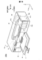
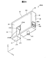
図1は、本発明の第1実施形態としての液体噴射システム1000の構成を示す斜視図である。図1には、互いに直交するXYZ軸が付されている。これ以降に示す図についても必要に応じてXYZ軸を付している。図1のXYZ軸は他の図のXYZ軸にも対応している。液体噴射システム1000は、液体供給ユニットとしてのカートリッジ20と、液体噴射装置としてのプリンター10とを備える。プリンター10は、キャリッジユニット60を備える。キャリッジユニット60は、カートリッジ20を装着可能なホルダーユニット61と、インクを外部に吐出可能なヘッドユニット50とを備える。カートリッジ20は、プリンター10のホルダーユニット61に着脱可能に装着される。 A. First embodiment:
A-1: Configuration of liquid ejection system:
FIG. 1 is a perspective view showing a configuration of aliquid ejection system 1000 as a first embodiment of the present invention. In FIG. 1, XYZ axes orthogonal to each other are attached. The XYZ axes are attached to the drawings shown thereafter as necessary. The XYZ axes in FIG. 1 also correspond to the XYZ axes in other figures. The liquid ejecting system 1000 includes a cartridge 20 as a liquid supply unit and a printer 10 as a liquid ejecting apparatus. The printer 10 includes a carriage unit 60. The carriage unit 60 includes a holder unit 61 on which the cartridge 20 can be mounted, and a head unit 50 that can eject ink to the outside. The cartridge 20 is detachably attached to the holder unit 61 of the printer 10.
A-1:液体噴射システムの構成:
図1は、本発明の第1実施形態としての液体噴射システム1000の構成を示す斜視図である。図1には、互いに直交するXYZ軸が付されている。これ以降に示す図についても必要に応じてXYZ軸を付している。図1のXYZ軸は他の図のXYZ軸にも対応している。液体噴射システム1000は、液体供給ユニットとしてのカートリッジ20と、液体噴射装置としてのプリンター10とを備える。プリンター10は、キャリッジユニット60を備える。キャリッジユニット60は、カートリッジ20を装着可能なホルダーユニット61と、インクを外部に吐出可能なヘッドユニット50とを備える。カートリッジ20は、プリンター10のホルダーユニット61に着脱可能に装着される。 A. First embodiment:
A-1: Configuration of liquid ejection system:
FIG. 1 is a perspective view showing a configuration of a
カートリッジ20は、内部にインクを収容する。カートリッジ20に収容されたインクは、後述する液体供給部及び液体導入針を流通してヘッドユニット50に供給される。本実施形態では、プリンター10のホルダーユニット61には、複数のカートリッジ20が着脱可能に装着される。本実施形態では、6色(ブラック、イエロー、マゼンタ、ライトマゼンタ、シアンおよびライトシアン)のインクに対応して6種類のカートリッジ20が1つずつ、すなわち合計6つ(図では1つのみ図示)のカートリッジ20がホルダーユニット61に装着される。なお、ホルダーユニット61に装着されるカートリッジ20の数は、6つに限定されるものではない。
The cartridge 20 contains ink inside. The ink stored in the cartridge 20 is supplied to the head unit 50 through a liquid supply unit and a liquid introduction needle which will be described later. In the present embodiment, a plurality of cartridges 20 are detachably mounted on the holder unit 61 of the printer 10. In the present embodiment, one of six types of cartridges 20 corresponding to six colors (black, yellow, magenta, light magenta, cyan, and light cyan), that is, a total of six (only one is shown in the figure). The cartridge 20 is mounted on the holder unit 61. Note that the number of cartridges 20 attached to the holder unit 61 is not limited to six.
プリンター10は、ホルダーユニット61に装着されたカートリッジ20内のインクを吸引することによって後述する液体導入針を介してヘッドユニット50にインクを流通させる。ヘッドユニット50は、圧電素子等の吐出機構を備え、紙やラベルなどの印刷媒体Pに対してインクを吐出(供給)する。これにより、印刷媒体Pに文字、図形および画像などのデータが印刷される。
The printer 10 causes ink to circulate through the head unit 50 via a liquid introduction needle described later by sucking ink in the cartridge 20 mounted on the holder unit 61. The head unit 50 includes a discharge mechanism such as a piezoelectric element, and discharges (supplies) ink to a print medium P such as paper or a label. Thereby, data such as characters, graphics, and images are printed on the print medium P.
プリンター10が備える制御部38は、プリンター10の各部を制御する。プリンター10のキャリッジユニット60は、ヘッドユニット50を印刷媒体Pに対して相対的に移動可能に構成されている。制御部38とキャリッジユニット60との間はフレキシブルケーブル37を介して電気的に接続されている。ヘッドユニット50の吐出機構は、制御部38からの制御信号に基づいて吐出動作を実行する。
The control unit 38 included in the printer 10 controls each unit of the printer 10. The carriage unit 60 of the printer 10 is configured to be able to move the head unit 50 relative to the print medium P. The control unit 38 and the carriage unit 60 are electrically connected via a flexible cable 37. The ejection mechanism of the head unit 50 performs an ejection operation based on a control signal from the control unit 38.
本実施形態では、キャリッジユニット60には、ヘッドユニット50と共にホルダーユニット61が構成されている。このように、ヘッドユニット50を移動させるキャリッジユニット60上のホルダーユニット61にカートリッジ20が装着されるプリンター10のタイプは、「オンキャリッジタイプ」とも呼ばれる。他の実施形態では、キャリッジユニット60とは異なる部位に、不動のホルダーユニット61を構成し、ホルダーユニット61に装着されたカートリッジ20からチューブを介してヘッドユニット50にインクを供給しても良い。このようなプリンターのタイプは、「オフキャリッジタイプ」とも呼ばれる。
In this embodiment, the carriage unit 60 includes a holder unit 61 together with the head unit 50. As described above, the type of the printer 10 in which the cartridge 20 is mounted on the holder unit 61 on the carriage unit 60 that moves the head unit 50 is also referred to as an “on-carriage type”. In another embodiment, an immovable holder unit 61 may be configured in a different part from the carriage unit 60, and ink may be supplied from the cartridge 20 mounted on the holder unit 61 to the head unit 50 via a tube. Such a printer type is also called an “off-carriage type”.
プリンター10は、更に、キャリッジユニット50と印刷媒体Pとを相対的に移動させて印刷媒体Pに対する印刷を実現するための主走査送り機構および副走査送り機構を備える。プリンター10の主走査送り機構は、キャリッジモーター13および駆動ベルト14を備える。駆動ベルト14を介してキャリッジモーター13の動力をキャリッジユニット60に伝達することによって、キャリッジユニット60を主走査方向に往復移動させる。プリンター10の副走査送り機構は、搬送モーター18およびプラテン12を備える。搬送モーター18の動力がプラテン12に伝達されることによって、主走査方向に直交する副走査方向に印刷媒体Pを搬送する。
The printer 10 further includes a main-scan feed mechanism and a sub-scan feed mechanism for moving the carriage unit 50 and the print medium P relative to each other to realize printing on the print medium P. The main scanning feed mechanism of the printer 10 includes a carriage motor 13 and a drive belt 14. By transmitting the power of the carriage motor 13 to the carriage unit 60 via the drive belt 14, the carriage unit 60 is reciprocated in the main scanning direction. The sub-scan feed mechanism of the printer 10 includes a transport motor 18 and a platen 12. When the power of the transport motor 18 is transmitted to the platen 12, the print medium P is transported in the sub-scanning direction orthogonal to the main scanning direction.
本実施形態では、液体噴射システム1000の使用状態(「使用姿勢」ともいう。)において、印刷媒体Pを搬送する副走査方向(前後方向)に沿った軸をY軸とし、キャリッジユニット60を往復移動させる主走査方向(左右方向)に沿った軸をX軸とし、重力方向(上下方向)に沿った軸をZ軸とする。なお、液体噴射システム1000の使用状態とは、水平な面に設置された液体噴射システム1000の状態であり、本実施形態では、水平な面はX軸およびY軸に平行な面(XY平面)である。
In the present embodiment, in the usage state (also referred to as “use posture”) of the liquid ejecting system 1000, the axis along the sub-scanning direction (front-rear direction) for transporting the print medium P is the Y axis, and the carriage unit 60 is reciprocated. An axis along the main scanning direction (left-right direction) to be moved is an X-axis, and an axis along the gravity direction (up-down direction) is a Z-axis. The usage state of the liquid ejecting system 1000 is a state of the liquid ejecting system 1000 installed on a horizontal surface. In the present embodiment, the horizontal surface is a surface parallel to the X axis and the Y axis (XY plane). It is.
本実施形態では、副走査方向(前方向)を+Y軸方向、その逆方向(後方向)を-Y軸方向とし、重力方向の下方から上方に向かう方向(上方向)を+Z軸方向、その逆方向(下方向)を-Z軸方向とする。本実施形態では、液体噴射システム1000の右側面から左側面に向かう方向を+X軸方向(左方向)、その逆方向を-X軸方向(右方向)とする。本実施形態では、ホルダーユニット61に装着された複数のカートリッジ20の配列方向はX軸に沿った方向(左右方向,「単に「X軸方向」とも呼ぶ。)である。なお、X軸に沿った方向(左右方向)を「X軸方向」とも呼び、Z軸に沿った方向(上下方向)を「Z軸方向」とも呼ぶ。また、本実施形態では、カートリッジ20のホルダーユニット61への装着方向は-Z軸方向であり、カートリッジ20をホルダーユニット61から取り外すための取り外し方向は+Z軸方向である。
In this embodiment, the sub-scanning direction (front direction) is the + Y axis direction, the opposite direction (rear direction) is the −Y axis direction, the direction from the lower side to the upper side of the gravity direction (upward direction) is the + Z axis direction, The reverse direction (downward) is taken as the -Z axis direction. In the present embodiment, the direction from the right side surface to the left side surface of the liquid ejecting system 1000 is the + X axis direction (left direction), and the opposite direction is the −X axis direction (right direction). In the present embodiment, the arrangement direction of the plurality of cartridges 20 attached to the holder unit 61 is a direction along the X axis (left-right direction, also simply referred to as “X-axis direction”). The direction along the X axis (left-right direction) is also referred to as “X-axis direction”, and the direction along the Z-axis (vertical direction) is also referred to as “Z-axis direction”. In this embodiment, the mounting direction of the cartridge 20 to the holder unit 61 is the −Z axis direction, and the removal direction for removing the cartridge 20 from the holder unit 61 is the + Z axis direction.
A-2.キャリッジユニット60の構成:
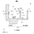
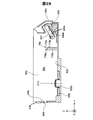
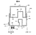
図2は、キャリッジユニット60の上面模式図である。図3は、図2のF2-F2断面模式図である。ホルダーユニット61(図2,図3)は、5つの壁部62,64,65,66,67を有する。壁部62を装置前壁部62とも呼び、壁部64を第1側壁部64とも呼び、壁部65を第2側壁部65とも呼び、壁部66を第3側壁部66とも呼び、壁部67を第4側壁部67とも呼ぶ。5つの壁部62,64,65,66,67は、例えば、合成樹脂によって成形されている。 A-2. Configuration of the carriage unit 60:
FIG. 2 is a schematic top view of thecarriage unit 60. FIG. 3 is a schematic cross-sectional view taken along line F2-F2 of FIG. The holder unit 61 (FIGS. 2 and 3) has five wall portions 62, 64, 65, 66, and 67. The wall portion 62 is also called the device front wall portion 62, the wall portion 64 is also called the first side wall portion 64, the wall portion 65 is also called the second side wall portion 65, and the wall portion 66 is also called the third side wall portion 66. 67 is also referred to as a fourth side wall portion 67. The five wall portions 62, 64, 65, 66, and 67 are formed of, for example, a synthetic resin.
図2は、キャリッジユニット60の上面模式図である。図3は、図2のF2-F2断面模式図である。ホルダーユニット61(図2,図3)は、5つの壁部62,64,65,66,67を有する。壁部62を装置前壁部62とも呼び、壁部64を第1側壁部64とも呼び、壁部65を第2側壁部65とも呼び、壁部66を第3側壁部66とも呼び、壁部67を第4側壁部67とも呼ぶ。5つの壁部62,64,65,66,67は、例えば、合成樹脂によって成形されている。 A-2. Configuration of the carriage unit 60:
FIG. 2 is a schematic top view of the
装置前壁部62は、ホルダーユニット61の底壁を構成する。装置前壁部62は、装着方向側に位置する。
The apparatus front wall 62 constitutes the bottom wall of the holder unit 61. The apparatus front wall 62 is located on the mounting direction side.
4つの壁部64,65,66,67は、装置前壁部62の周縁部から+Z軸方向(取り外し方向)に延びる。これら5つの壁部62,64,65,66,67によって凹部が形成される。この凹部が、カートリッジ20を収容するカートリッジ収容室69(「カートリッジ装着部69」とも呼ぶ)を形成する。また、カートリッジ収容室69は、各カートリッジ20を受け入れ可能な複数のスロット(装着空間)69A~69Fを有する。複数のスロット69A~69Fは、例えば、装置前壁部62に板状の仕切り壁を設けることで分割されても良い。
The four wall portions 64, 65, 66, 67 extend in the + Z-axis direction (removal direction) from the peripheral portion of the device front wall portion 62. A recess is formed by these five wall portions 62, 64, 65, 66 and 67. This recess forms a cartridge housing chamber 69 (also referred to as “cartridge mounting portion 69”) that houses the cartridge 20. The cartridge storage chamber 69 has a plurality of slots (mounting spaces) 69A to 69F that can receive the cartridges 20. The plurality of slots 69A to 69F may be divided, for example, by providing a plate-like partition wall on the apparatus front wall 62.
第1側壁部64と第2側壁部65とはY軸方向に対向する。第3側壁部66と第4側壁部67とはX軸方向に対向する。本実施形態におけるホルダーユニット61では、Z軸方向は高さ方向であり、Y軸方向は長さ方向であり、X軸方向は幅方向である。
The first side wall portion 64 and the second side wall portion 65 face each other in the Y-axis direction. The third side wall portion 66 and the fourth side wall portion 67 face each other in the X-axis direction. In the holder unit 61 in the present embodiment, the Z-axis direction is the height direction, the Y-axis direction is the length direction, and the X-axis direction is the width direction.
ホルダーユニット61はスロット69A~69F毎に、液体導入部としての液体導入針622と、係合構造70と、電極部644と、を備える。
The holder unit 61 includes a liquid introduction needle 622 as a liquid introduction portion, an engagement structure 70, and an electrode portion 644 for each of the slots 69A to 69F.
液体導入針622(図3)は、装置前壁部62に配置されている。液体導入針622は、装置前壁部62から+Z軸方向に突出する。液体導入針622の内部には、インクが流通可能な流路が形成されている。液体導入針622は、-Z軸方向(装着方向)に沿って延びる。液体導入針622は、装置前壁部62側に位置する基端部622sと、基端部622sとは反対側の先端部622tとを有する。本実施形態の液体導入針622は、横断面が略円形であり、装着方向(+Z軸方向)に沿って延びる中心軸CTを有する。基端部622sから先端部622tに向かう方向が+Z軸方向であり、先端部622tから基端部622sに向かう方向が-Z軸方向である。液体導入針622は、ヘッドユニット50と連通する。
The liquid introduction needle 622 (FIG. 3) is disposed on the front wall portion 62 of the apparatus. The liquid introduction needle 622 protrudes from the device front wall 62 in the + Z axis direction. Inside the liquid introduction needle 622, a flow path through which ink can flow is formed. The liquid introduction needle 622 extends along the −Z axis direction (mounting direction). The liquid introduction needle 622 has a proximal end portion 622s located on the apparatus front wall portion 62 side and a distal end portion 622t opposite to the proximal end portion 622s. The liquid introduction needle 622 of the present embodiment has a substantially circular cross section and has a central axis CT extending along the mounting direction (+ Z axis direction). The direction from the base end 622s to the tip end 622t is the + Z-axis direction, and the direction from the tip end 622t to the base end 622s is the −Z-axis direction. The liquid introduction needle 622 communicates with the head unit 50.
係合構造70は、装置前壁部62から取り外し方向(+Z軸方向)に延びる柱状の部材である。係合構造70は、装置前壁部62から取り外し方向に延びる本体部772と、本体部772の端部(取り外し方向側端部)に接続された係合部776と、を備える。係合構造70は、例えば、合成樹脂によって装置前壁部62と一体成形されていても良いし、装置前壁部62と別部材によって成形されていても良い。
The engagement structure 70 is a columnar member extending from the device front wall 62 in the removal direction (+ Z axis direction). The engagement structure 70 includes a main body portion 772 extending in the removal direction from the device front wall portion 62, and an engagement portion 776 connected to an end portion (removal direction side end portion) of the main body portion 772. For example, the engagement structure 70 may be integrally formed with the device front wall portion 62 by synthetic resin, or may be formed by a separate member from the device front wall portion 62.
本体部772は、柱状の部材である。本体部772の一端部772sは装置前壁部62に接続されている。本体部772は、外力によって一端部772sを支点として、本体部772が弾性変形することで、他端部772tがY軸方向成分を有する方向RMに移動可能に構成されている。本体部772に加えられる外力は、例えば、カートリッジ20の装着過程において、係合構造70がカートリッジ20に当接することで加えられる力である。
The main body 772 is a columnar member. One end 772 s of the main body 772 is connected to the device front wall 62. The main body 772 is configured to be movable in a direction RM in which the other end 772t has a Y-axis direction component by elastically deforming the main body 772 with the one end 772s as a fulcrum by an external force. The external force applied to the main body 772 is, for example, a force applied by the engagement structure 70 coming into contact with the cartridge 20 in the mounting process of the cartridge 20.
係合部776は、本体部772の他端部772tに接続された突起である。係合部776は、本体部772の他端部772tから取り外し方向(+Z軸方向)及び取り外し方向と直交し、第2側壁部65から第1側壁部64に向かう方向(詳細には、-Y軸方向)に突出する。係合部776は、カートリッジ20がホルダーユニット61に装着された装着状態において、カートリッジ20(詳細には、後述する被係合部)と係合可能である。係合部776とカートリッジ20の被係合部とが係合することで、装着状態におけるカートリッジ20の取り外し方向(+Z軸方向)への動きが規制される。
The engaging portion 776 is a protrusion connected to the other end portion 772 t of the main body portion 772. The engaging portion 776 is detached from the other end 772t of the main body 772t (+ Z axis direction) and perpendicular to the removing direction, and is directed from the second side wall 65 to the first side wall 64 (specifically, -Y Project in the axial direction). The engaging portion 776 can be engaged with the cartridge 20 (specifically, an engaged portion described later) in a mounted state where the cartridge 20 is mounted on the holder unit 61. Engagement of the engaging portion 776 and the engaged portion of the cartridge 20 restricts movement of the cartridge 20 in the removal direction (+ Z-axis direction) in the mounted state.
係合部776は、案内面775と、係合形成面774と、を備える。案内面775は、カートリッジ20の装着過程においてカートリッジ20と当接する。この当接によって、他端部772tは-Y軸方向側に移動する。案内面775は、カートリッジ20を係合位置まで導くための部材である。案内面775は、取り外し方向(-Z軸方向)と取り外し方向と直交する方向の成分を含む方向を向く。本実施形態では、案内面775は、取り外し方向(-Z軸方向)と取り外し方向と直交し第2側壁部65から第1側壁部64に向かう方向(-Y軸方向)の成分を含む方向を向く。「面(要素)が方向を向く」とは、面(要素)の法線ベクトルVeの向きを対象としている。つまり、案内面775の法線ベクトルVe1の向きは、+Z軸方向成分と-Y軸方向成分を含む方向である。係合形成面774は、カートリッジ20の装着状態において、カートリッジ20の被係合部と係合する。係合形成面774は、水平な面であり、装着方向(-Z軸方向)を向く面である。係合形成面774は、本体部772からホルダー側端子645が位置する側(-Y軸方向側)に延びる。係合形成面774は、カートリッジ20の取り外し方向への動きを規制するために、後述するカートリッジ20の被係合部と係合可能な形状であれば、本実施形態に限定されるものではない。例えば、係合形成面774は、取り外し方向に対して傾斜していても良いし、平面に代えて凹凸を有する面であっても良い。また、係合形成面に代えて、カートリッジ20の被係合部と嵌め合わされることで係合可能な形状が採用されても良い。
The engaging portion 776 includes a guide surface 775 and an engagement forming surface 774. The guide surface 775 contacts the cartridge 20 in the mounting process of the cartridge 20. By this contact, the other end 772t moves to the −Y axis direction side. The guide surface 775 is a member for guiding the cartridge 20 to the engagement position. The guide surface 775 faces in a direction including a component in a direction perpendicular to the removal direction (−Z axis direction) and the removal direction. In the present embodiment, the guide surface 775 has a direction including a component in a direction (−Y axis direction) from the second side wall 65 toward the first side wall 64 perpendicular to the removal direction (−Z axis direction) and the removal direction. Turn to. “The face (element) faces the direction” is directed to the direction of the normal vector Ve of the face (element). That is, the direction of the normal vector Ve1 of the guide surface 775 is a direction including a + Z-axis direction component and a −Y-axis direction component. The engagement forming surface 774 engages with the engaged portion of the cartridge 20 in the mounted state of the cartridge 20. The engagement forming surface 774 is a horizontal surface that faces the mounting direction (−Z-axis direction). The engagement forming surface 774 extends from the main body portion 772 to the side where the holder side terminal 645 is located (−Y axis direction side). The engagement forming surface 774 is not limited to the present embodiment as long as the engagement forming surface 774 has a shape that can be engaged with an engaged portion of the cartridge 20 described later in order to restrict movement of the cartridge 20 in the removal direction. . For example, the engagement forming surface 774 may be inclined with respect to the removal direction, or may be a surface having irregularities instead of a flat surface. Further, instead of the engagement forming surface, a shape that can be engaged by being engaged with the engaged portion of the cartridge 20 may be employed.
係合構造70は、さらに、係合部776を矢印RMに示す方向に移動させるための装置側操作部(図示せず)を有しても良い。装置側操作部は、利用者によって操作できる位置に配置されている。装置側操作部は、係合形成面774とカートリッジ20との係合を解除するために用いられる。装置側操作部は、例えば、他端部772tに連結された棒状の部材である。例えば、装置側操作部の一部は、装置前壁部62から外方に突出している。利用者は、装置側操作部に外力を加えることで、係合部776を移動させることができる。
The engagement structure 70 may further include a device-side operation unit (not shown) for moving the engagement unit 776 in the direction indicated by the arrow RM. The apparatus side operation part is arrange | positioned in the position which can be operated by the user. The apparatus-side operation unit is used for releasing the engagement between the engagement forming surface 774 and the cartridge 20. The device-side operation unit is, for example, a rod-shaped member connected to the other end 772t. For example, a part of the apparatus side operation part protrudes outward from the apparatus front wall part 62. The user can move the engaging portion 776 by applying an external force to the apparatus-side operation portion.
電極部644は、複数のホルダー側端子645を有する。電極部644は、第1側壁部64に設けられている。本実施形態では、ホルダー側端子645は、9個設けられている。なお、ホルダー側端子645の個数はこれに限定されるものではなく、9個より少なくても良いし9個より多くても良い。ホルダー側端子645は、制御部38(図1)に電気的に接続されている。ホルダー側端子645は、一部がカートリッジ収容室69内に位置する。ホルダー側端子645は、板状の金属製部材であり、少なくともY軸方向に弾性変形可能なように構成されている。装着状態において、各ホルダー側端子645は、カートリッジ20の対応する部材(接触部)と接触することで接触部と電気的に接続される。また、装着状態において、各ホルダー側端子645は、-Y軸方向側に弾性変形することによって、カートリッジ20を+Y軸方向側へ付勢する。
The electrode portion 644 has a plurality of holder side terminals 645. The electrode part 644 is provided on the first side wall part 64. In the present embodiment, nine holder side terminals 645 are provided. The number of holder side terminals 645 is not limited to this, and may be less than nine or more than nine. The holder side terminal 645 is electrically connected to the control unit 38 (FIG. 1). A part of the holder side terminal 645 is located in the cartridge housing chamber 69. The holder side terminal 645 is a plate-shaped metal member and is configured to be elastically deformable at least in the Y-axis direction. In the mounted state, each holder-side terminal 645 is electrically connected to the contact portion by contacting a corresponding member (contact portion) of the cartridge 20. In the mounted state, each holder-side terminal 645 urges the cartridge 20 toward the + Y-axis direction side by elastically deforming toward the −Y-axis direction side.
図3に示すように、Y軸方向(第1方向)において、第1側壁部64の内表面と第2側壁部65の内表面との中央を中央部CPaとし、中央部CPaに対して第1側壁部64側を一方の側RAとし、中央部CPaに対して第2側壁部65側を他方の側RBとする。この場合において、ホルダーユニット61が備える各部は以下の位置関係を有する。すなわち、液体導入針622,電極部644は一方の側RAに位置し、係合部776は他方の側RBに位置する。
As shown in FIG. 3, in the Y-axis direction (first direction), the center between the inner surface of the first side wall portion 64 and the inner surface of the second side wall portion 65 is a central portion CPa, and One side wall portion 64 side is set as one side RA, and the second side wall portion 65 side is set as the other side RB with respect to the central portion CPa. In this case, each part with which the holder unit 61 is provided has the following positional relationship. That is, the liquid introduction needle 622 and the electrode portion 644 are located on one side RA, and the engaging portion 776 is located on the other side RB.
A-3.カートリッジ20の構成:
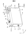
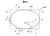
図4は、第1実施形態のカートリッジ20の斜視図である。図5は、カートリッジ20の断面図である。図4及び図5には装着状態におけるXYZ軸を付している。なお、これ以降お図においても、必要に応じて、装着状態におけるXYZ軸を付している。 A-3. Configuration of cartridge 20:
FIG. 4 is a perspective view of thecartridge 20 of the first embodiment. FIG. 5 is a cross-sectional view of the cartridge 20. 4 and 5 are attached with XYZ axes in the mounted state. In the following drawings, XYZ axes in the mounted state are attached as necessary.
図4は、第1実施形態のカートリッジ20の斜視図である。図5は、カートリッジ20の断面図である。図4及び図5には装着状態におけるXYZ軸を付している。なお、これ以降お図においても、必要に応じて、装着状態におけるXYZ軸を付している。 A-3. Configuration of cartridge 20:
FIG. 4 is a perspective view of the
カートリッジ20(図4)は、外殻28と、液体収容部201と、液体供給部212と、回路基板40と、被係合構造27と、を備える。
The cartridge 20 (FIG. 4) includes an outer shell 28, a liquid storage unit 201, a liquid supply unit 212, a circuit board 40, and an engaged structure 27.
外殻28は、カートリッジ20の外表面を形成する。外殻28は、カートリッジ20の本体であり、液体収容部201を含む内部空間を区画規定する。外殻28はポリプロピレン(PP)等の合成樹脂により形成されている。外殻28は、略角柱形状又は略直方体形状である。なお、外殻28の一部は、樹脂製フィルムにより形成されていても良い。
The outer shell 28 forms the outer surface of the cartridge 20. The outer shell 28 is a main body of the cartridge 20 and defines an internal space including the liquid storage unit 201. The outer shell 28 is made of a synthetic resin such as polypropylene (PP). The outer shell 28 has a substantially prismatic shape or a substantially rectangular parallelepiped shape. Part of the outer shell 28 may be formed of a resin film.
外殻28は、第1壁部21と、第2壁部22と、第3壁部23と、第4壁部24と、第5壁部25と、第6壁部26とを有する。第1壁部21~第6壁部26の外表面は、それぞれ概ね平面である。「概ね平面」とは、面全域が完全に平坦である場合と、面の一部に凹凸を有する場合を含む。つまり、面の一部に多少の凹凸があっても、カートリッジ20の外殻28を構成する面や壁が把握できるような場合を含む。第1壁部21~第6壁部26の平面視における外形は、いずれも略長方形である。
The outer shell 28 includes a first wall portion 21, a second wall portion 22, a third wall portion 23, a fourth wall portion 24, a fifth wall portion 25, and a sixth wall portion 26. The outer surfaces of the first wall portion 21 to the sixth wall portion 26 are each generally flat. The “substantially flat” includes the case where the entire surface is completely flat and the case where the surface is partially uneven. That is, it includes a case where the surface or wall constituting the outer shell 28 of the cartridge 20 can be grasped even if there is some unevenness on a part of the surface. The outer shapes of the first wall portion 21 to the sixth wall portion 26 in plan view are all substantially rectangular.
第1壁部21は、装着状態において水平な底面を構成する。第1壁部21は、装着方向(-Z軸方向)の成分を有する方向を向く。本実施形態では、第1壁部21は装着方向を向く。つまり、本実施形態では、第1壁部21の外表面の法線ベクトルの向きは、装着方向である。ここで、第1壁部21を「先端側部分21」とも呼ぶ。第1壁部(先端側部分)21は、外殻28のうち装着方向側に位置する部分であるとも言える。また、第1壁部(先端側部分)21は、液体導入針622が設けられた装置前壁部62(図3)と向かい合う部分である。なお、第1壁部21は、装着方向を向いていたがこれに限定されるものではなく、装着方向の成分を有する方向を向いていれば良い。
The first wall portion 21 constitutes a horizontal bottom surface in the mounted state. The first wall portion 21 faces a direction having a component in the mounting direction (−Z-axis direction). In the present embodiment, the first wall portion 21 faces the mounting direction. That is, in this embodiment, the direction of the normal vector on the outer surface of the first wall portion 21 is the mounting direction. Here, the first wall portion 21 is also referred to as a “tip side portion 21”. It can be said that the first wall portion (front end side portion) 21 is a portion located on the mounting direction side of the outer shell 28. The first wall portion (front end side portion) 21 is a portion facing the device front wall portion 62 (FIG. 3) where the liquid introduction needle 622 is provided. In addition, although the 1st wall part 21 faced the mounting direction, it is not limited to this, What is necessary is just to face the direction which has a component of a mounting direction.
第2壁部22は、装着状態において水平な上面を構成する。第2壁部22は、第1壁部21と対向する。第2壁部22は、装着方向とは反対の取り外し方向側に位置する。第2壁部22は、取り外し方向(+Z軸方向)の成分を有する方向を向く部分である。本実施形態では、第2壁部22は、取り外し方向を向く。第2壁部22を「後端側部分22」とも呼ぶ。なお、本明細書において、「2つの要素が対向する場合」とは、2つの要素の間に他の要素が位置する場合と、2つの要素の間に他の要素が位置しない場合のいずれかの場合を含む。第2壁部22には、大気導入口220(図5)が形成されている。大気導入口220は、液体収容部201のインクの消費に伴って液体収容部201に空気を導入する。また、カートリッジ20は、第2壁部22などに液体収容部201にインクを注入するための液体注入口を有していても良い。
The second wall portion 22 constitutes a horizontal upper surface in the mounted state. The second wall portion 22 faces the first wall portion 21. The second wall portion 22 is located on the removal direction side opposite to the mounting direction. The 2nd wall part 22 is a part which faces the direction which has a component of a removal direction (+ Z-axis direction). In the present embodiment, the second wall portion 22 faces the removal direction. The second wall portion 22 is also referred to as a “rear end portion 22”. In this specification, “when two elements face each other” means either a case where another element is located between the two elements or a case where no other element is located between the two elements. Including the case. An air inlet 220 (FIG. 5) is formed in the second wall portion 22. The air inlet 220 introduces air into the liquid container 201 as the ink in the liquid container 201 is consumed. Further, the cartridge 20 may have a liquid injection port for injecting ink into the liquid storage unit 201 on the second wall portion 22 or the like.
第3壁部23は、装着状態において背面を構成する。第3壁部23は、第1壁部21と第2壁部と交差する。第3壁部23の外表面は、X軸方向及びZ軸方向に平行で、Y軸方向に垂直な面(XZ平面)である。なお、本明細書では、2つの要素(例えば、壁部や面)が「交差する」とは、2つの要素が相互に実際に交差する状態と、一方の要素を延長した場合に他方の要素に交差する状態と、相互に延長した場合に延長した部分が交差する状態と、のいずれかの状態であることを意味する。
3rd wall part 23 comprises a back surface in a mounting state. The third wall portion 23 intersects the first wall portion 21 and the second wall portion. The outer surface of the third wall portion 23 is a surface (XZ plane) parallel to the X-axis direction and the Z-axis direction and perpendicular to the Y-axis direction. In this specification, two elements (for example, a wall or a surface) “intersect” means that the two elements actually intersect each other and the other element when one element is extended. It means that the state intersects with each other and the state where the extended portions intersect when they extend to each other.
第4壁部24は、装着状態において正面を構成する。第4壁部24は、第1壁部21と第2壁部22と交差する。また、第4壁部24は、第3壁部23と対向する。第4壁部24の外表面は、X軸方向及びZ軸方向に平行で、Y軸方向に垂直な面(YZ平面)である。
4th wall part 24 comprises a front surface in a mounting state. The fourth wall portion 24 intersects the first wall portion 21 and the second wall portion 22. Further, the fourth wall portion 24 faces the third wall portion 23. The outer surface of the fourth wall portion 24 is a surface (YZ plane) parallel to the X-axis direction and the Z-axis direction and perpendicular to the Y-axis direction.
第5壁部25は、装着状態において右側面を構成する。第6壁部26は、装着状態において左側面を構成する。第5壁部25と第6壁部26は対向する。第5壁部25と第6壁部26とはそれぞれ、第1~第4壁部21~24と交差する。第5壁部25と第6壁部26とのそれぞれの外表面は、Y軸方向及びZ軸方向に平行で、X軸方向に垂直な面(YZ平面)である。第5壁部25と第6壁部26とは、互いに対向する。
The fifth wall 25 constitutes the right side surface in the mounted state. The sixth wall portion 26 constitutes the left side surface in the mounted state. The fifth wall portion 25 and the sixth wall portion 26 face each other. The fifth wall portion 25 and the sixth wall portion 26 intersect with the first to fourth wall portions 21 to 24, respectively. The outer surfaces of the fifth wall portion 25 and the sixth wall portion 26 are surfaces (YZ plane) parallel to the Y-axis direction and the Z-axis direction and perpendicular to the X-axis direction. The fifth wall portion 25 and the sixth wall portion 26 face each other.
外殻28は、第5壁部25と第6壁部とが対向する方向(X軸方向)の寸法が、第1壁部21と第2壁部22とが対向する方向(Z軸方向)の寸法および第3壁部23と第4壁部24とが対向する方向(Y軸方向)の寸法よりも小さい。つまり、第3壁部23と第4壁部24との距離は、第5壁部25と第6壁部との距離よりも長い。
The outer shell 28 has a dimension in a direction in which the fifth wall portion 25 and the sixth wall portion face each other (X-axis direction), and a direction in which the first wall portion 21 and the second wall portion 22 face each other (Z-axis direction). And the dimension in the direction (Y-axis direction) in which the third wall portion 23 and the fourth wall portion 24 face each other. That is, the distance between the third wall portion 23 and the fourth wall portion 24 is longer than the distance between the fifth wall portion 25 and the sixth wall portion.
装着方向(Z軸方向)と直交するY軸方向を第1方向とも呼ぶ。本実施形態では、第1方向は、第3壁部23と第4壁部24とが対向する方向である。言い換えれば、第1方向は、装着方向と直交する2方向(X軸方向とY軸方向)のうち、外殻28の寸法が大きい方向である。図5に示すように、カートリッジ20において、第3壁部23の外表面と第4壁部24の外表面との中央が第1方向における中央部CPbとなり、中央部CPbに対して第3壁部23側が一方の側RAとなり、中央部CPbに対して第4壁部24側が他方の側RBとなる。
The Y-axis direction orthogonal to the mounting direction (Z-axis direction) is also referred to as the first direction. In the present embodiment, the first direction is a direction in which the third wall portion 23 and the fourth wall portion 24 face each other. In other words, the first direction is a direction in which the dimension of the outer shell 28 is large among two directions (X-axis direction and Y-axis direction) orthogonal to the mounting direction. As shown in FIG. 5, in the cartridge 20, the center of the outer surface of the third wall portion 23 and the outer surface of the fourth wall portion 24 is the central portion CPb in the first direction, and the third wall is located with respect to the central portion CPb. The portion 23 side is one side RA, and the fourth wall portion 24 side is the other side RB with respect to the central portion CPb.
液体収容部201(図5)は、ヘッドユニット50に供給するためのインクを収容する。液体収容部201は、外殻28によって区画形成されている。
The liquid storage unit 201 (FIG. 5) stores ink to be supplied to the head unit 50. The liquid container 201 is defined by the outer shell 28.
液体供給部212は、液体導入針622(図3)と接続可能である。液体供給部212は、第1壁部21に形成された連通孔205を介して液体収容部201と連通する。つまり、液体供給部212は、プリンター10にインクを供給可能である。液体供給部212は、外殻28の先端側部分を構成する第1壁部21に配置されている。また、液体供給部212は、第1方向において、一方の側RAに配置されている。液体供給部212は、第1壁部21から装着方向に突出する筒状の部材である。液体供給部212の先端は開口している。液体供給部212は、先端の開口を介して、液体収容部201が収容するインクを外部(例えば、液体導入針622)に流通させる。装着状態では、筒状の液体供給部212内に液体導入針622が挿入されることで、液体供給部212が液体導入針622に接続される。この接続によって、液体供給部212から液体導入針622へのインクの流通が可能となる。
The liquid supply unit 212 can be connected to the liquid introduction needle 622 (FIG. 3). The liquid supply unit 212 communicates with the liquid storage unit 201 through a communication hole 205 formed in the first wall portion 21. That is, the liquid supply unit 212 can supply ink to the printer 10. The liquid supply unit 212 is disposed on the first wall portion 21 that constitutes the tip side portion of the outer shell 28. Further, the liquid supply unit 212 is disposed on one side RA in the first direction. The liquid supply part 212 is a cylindrical member that protrudes from the first wall part 21 in the mounting direction. The tip of the liquid supply unit 212 is open. The liquid supply unit 212 distributes the ink stored in the liquid storage unit 201 to the outside (for example, the liquid introduction needle 622) through the opening at the tip. In the mounted state, the liquid introduction needle 622 is inserted into the cylindrical liquid supply section 212, whereby the liquid supply section 212 is connected to the liquid introduction needle 622. This connection enables ink to flow from the liquid supply unit 212 to the liquid introduction needle 622.
液体供給部212の内部には、弁機構29が配置されている。弁機構29によって、液体供給部212の内部流路が開閉される。弁機構29は、液体供給部212の先端側から順に、シール部(弁座)29Aと、弁体29Bと、付勢部材29Cとを備える。シール部29Aは、略円環状の部材である。シール部29Aは、例えば、ゴムやエラストマー等の弾性体によって構成されている。シール部29Aは、液体供給部57の内部に圧入されている。弁体29Bは、略円柱状の部材である。弁体29Bは、カートリッジ20がホルダーユニット61に装着される前の状態(未装着状態)において、シール部29Aに形成された孔(弁孔)を塞ぐ。付勢部材29Cは、圧縮コイルばねである。付勢部材29Cは、弁体29Bをシール部29A側に向かう方向に付勢する。カートリッジ20の装着状態では、液体導入針622(図3)が弁体29Bをシール部29Aから離れる方向に向けて押すことで、弁体29Bがシール部29Aから離れる。これにより、弁機構29が開状態になる。
A valve mechanism 29 is disposed inside the liquid supply unit 212. The valve mechanism 29 opens and closes the internal flow path of the liquid supply unit 212. The valve mechanism 29 includes a seal portion (valve seat) 29A, a valve body 29B, and an urging member 29C in order from the distal end side of the liquid supply portion 212. The seal portion 29A is a substantially annular member. The seal portion 29A is made of an elastic body such as rubber or elastomer, for example. The seal portion 29 </ b> A is press-fitted inside the liquid supply portion 57. The valve body 29B is a substantially columnar member. The valve body 29 </ b> B closes the hole (valve hole) formed in the seal portion 29 </ b> A before the cartridge 20 is attached to the holder unit 61 (non-attached state). The urging member 29C is a compression coil spring. The urging member 29C urges the valve body 29B in the direction toward the seal portion 29A. In the mounted state of the cartridge 20, the liquid introduction needle 622 (FIG. 3) pushes the valve body 29 </ b> B in the direction away from the seal portion 29 </ b> A, whereby the valve body 29 </ b> B is separated from the seal portion 29 </ b> A. As a result, the valve mechanism 29 is opened.
回路基板40(図4)は、カートリッジ20の装着状態において、制御部38(図1)と電気的に接続される。回路基板40の表面40faには、複数のユニット側端子432が設けられている。複数のユニット側端子432は、ホルダー側端子645(図3)の数に対応して9個設けられている。各ユニット側端子432の外形は略矩形状である。略矩形状のユニット側端子432の中央部が、対応するホルダー側端子645と接触することで、ユニット側端子432とホルダー側端子645とが電気的に接続可能である。よって、ユニット側端子432を接触部432とも呼ぶ。回路基板40の裏面には、記憶装置などの電気デバイス(図示省略)が設けられている。この電気デバイスは、ユニット側端子432と配線で接続されている。例えば、記憶装置には、カートリッジ20のインクに関する情報(インク残量やインク色)等が格納される。カートリッジ20の装着状態において、記憶装置と制御部38(図1)との間で信号のやり取りが行われる。
The circuit board 40 (FIG. 4) is electrically connected to the control unit 38 (FIG. 1) when the cartridge 20 is mounted. A plurality of unit-side terminals 432 are provided on the surface 40fa of the circuit board 40. A plurality of unit side terminals 432 are provided corresponding to the number of holder side terminals 645 (FIG. 3). The outer shape of each unit side terminal 432 is substantially rectangular. The unit-side terminal 432 and the holder-side terminal 645 can be electrically connected by the center portion of the substantially rectangular unit-side terminal 432 coming into contact with the corresponding holder-side terminal 645. Therefore, the unit side terminal 432 is also referred to as a contact portion 432. An electrical device (not shown) such as a storage device is provided on the back surface of the circuit board 40. This electrical device is connected to the unit side terminal 432 by wiring. For example, the storage device stores information (ink remaining amount and ink color) related to the ink of the cartridge 20. In the mounted state of the cartridge 20, signals are exchanged between the storage device and the control unit 38 (FIG. 1).
回路基板40(図5)は、第1方向(Y軸方向)における一方の側RAに位置する第3壁部23に配置されている。回路基板40の表面40faの法線ベクトルの向きは、-Y軸方向である。ユニット側端子432は、第2方向において、一方の側RAに配置されている。
The circuit board 40 (FIG. 5) is disposed on the third wall portion 23 located on one side RA in the first direction (Y-axis direction). The direction of the normal vector of the surface 40fa of the circuit board 40 is the −Y axis direction. The unit side terminal 432 is disposed on one side RA in the second direction.
被係合構造27は、被係合部274と、受入部275と、第1開口部272とを有する。被係合構造27は、第1壁部21に形成された凹部である。被係合構造27は、カートリッジ20が備える内壁部271によって区画形成されている。受入部275は、装着状態において柱状の係合構造70(図3)を受け入れる。受入部275は、本体部772を受け入れる第1受入部275Aと、係合部776を受け入れる第2受入部275Bとを有する。第1受入部275Aは、第2受入部275Bよりも装着方向側に位置する。第1受入部275Aと第2受入部275Bとの境界部には段差が形成される。この段差によって被係合部274が形成される。
The engaged structure 27 includes an engaged portion 274, a receiving portion 275, and a first opening 272. The engaged structure 27 is a recess formed in the first wall portion 21. The engaged structure 27 is defined by an inner wall portion 271 provided in the cartridge 20. The receiving portion 275 receives the columnar engagement structure 70 (FIG. 3) in the mounted state. The receiving portion 275 includes a first receiving portion 275A that receives the main body portion 772, and a second receiving portion 275B that receives the engaging portion 776. The first receiving portion 275A is located closer to the mounting direction than the second receiving portion 275B. A step is formed at the boundary between the first receiving portion 275A and the second receiving portion 275B. The engaged portion 274 is formed by this step.
第1開口部272は、第1壁部21に形成された開口である。第1開口部272は、凹部である受入部275の開口であるとも言える。第1開口部272は、係合構造70の本体部772が挿通可能に開口する。第1開口部272の開口方向は、装着方向(-Z軸方向)である。開口方向とは、カートリッジ20の内側から外側に向かう第1開口部272の開口面の法線ベクトルVe2(図5)の向きである。
The first opening 272 is an opening formed in the first wall 21. It can be said that the 1st opening part 272 is an opening of the receiving part 275 which is a recessed part. The first opening 272 opens so that the main body 772 of the engagement structure 70 can be inserted. The opening direction of the first opening 272 is the mounting direction (−Z axis direction). The opening direction is the direction of the normal vector Ve2 (FIG. 5) of the opening surface of the first opening 272 from the inside of the cartridge 20 toward the outside.
被係合部274は、プリンター10の係合部776(図3)と係合可能である。被係合部274は、被係合構造27を区画規定する内壁部271によって形成されている。被係合部274は、取り外し方向(-Z軸方向)を向く面である。被係合部274は、凹部である受入部275の側壁部を形成する一つの壁部278から第1方向においてユニット側端子432が位置する側(-Y軸方向側)に延びる。壁部278は、第1受入部275Aの側壁部のうち、第1方向においてユニット側端子432側(-Y軸方向側)に位置する。また、壁部278は、第1開口部272を区画規定する。被係合部274は、外殻28の外表面よりも内側に配置されている。つまり、被係合部274は、外殻28の外表面によって取り囲まれた領域内に配置されている。また、被係合部274は、第1壁部21と第2壁部22との間に配置されている。また、被係合部274は、第3壁部23と第4壁部24との間に配置されている。また、被係合部274は、第5壁部25と第6壁部26との間に配置されている。被係合部274の構成は、本実施形態に限定されるものではなく、係合部776と係合することでカートリッジ20の取り外し方向への動きを規制できれば良い。例えば、係合部776が水平方向に延びる突起であり、被係合部274が突起である係合部776を受け入れる貫通孔部であっても良い。
The engaged portion 274 can be engaged with an engaging portion 776 (FIG. 3) of the printer 10. The engaged portion 274 is formed by an inner wall portion 271 that defines the engaged structure 27. The engaged portion 274 is a surface facing the removal direction (−Z axis direction). The engaged portion 274 extends from one wall portion 278 forming a side wall portion of the receiving portion 275 that is a concave portion to the side where the unit side terminal 432 is located in the first direction (−Y axis direction side). The wall portion 278 is located on the unit side terminal 432 side (−Y-axis direction side) in the first direction in the side wall portion of the first receiving portion 275A. The wall 278 defines the first opening 272. The engaged portion 274 is disposed inside the outer surface of the outer shell 28. That is, the engaged portion 274 is disposed in a region surrounded by the outer surface of the outer shell 28. Further, the engaged portion 274 is disposed between the first wall portion 21 and the second wall portion 22. Further, the engaged portion 274 is disposed between the third wall portion 23 and the fourth wall portion 24. Further, the engaged portion 274 is disposed between the fifth wall portion 25 and the sixth wall portion 26. The configuration of the engaged portion 274 is not limited to the present embodiment, and it is sufficient that the movement of the cartridge 20 in the removal direction can be restricted by engaging with the engaging portion 776. For example, the engaging portion 776 may be a protrusion extending in the horizontal direction, and the engaged portion 274 may be a through-hole portion that receives the engaging portion 776 that is a protrusion.
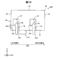
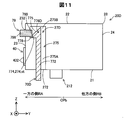
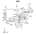
A-4.カートリッジ20のホルダーユニット61への装着態様:
図6は、カートリッジ20のホルダーユニット61への装着過程を示す図である。図7は、カートリッジ20のホルダーユニット61への装着状態を示す図である。カートリッジ20をホルダーユニット61に装着する場合、利用者は、カートリッジ20をカートリッジ収容室69に向けて装着方向に移動させる。具体的には、液体導入針622が液体供給部212内に挿入されるように、液体導入針622の中心軸CT上に液体供給部212を位置させつつ、カートリッジ20を装着方向に移動させる。 A-4. Mounting mode of thecartridge 20 to the holder unit 61:
FIG. 6 is a diagram illustrating a process of attaching thecartridge 20 to the holder unit 61. FIG. 7 is a diagram illustrating a mounting state of the cartridge 20 to the holder unit 61. When mounting the cartridge 20 in the holder unit 61, the user moves the cartridge 20 toward the cartridge storage chamber 69 in the mounting direction. Specifically, the cartridge 20 is moved in the mounting direction while the liquid supply unit 212 is positioned on the central axis CT of the liquid introduction needle 622 so that the liquid introduction needle 622 is inserted into the liquid supply unit 212.
図6は、カートリッジ20のホルダーユニット61への装着過程を示す図である。図7は、カートリッジ20のホルダーユニット61への装着状態を示す図である。カートリッジ20をホルダーユニット61に装着する場合、利用者は、カートリッジ20をカートリッジ収容室69に向けて装着方向に移動させる。具体的には、液体導入針622が液体供給部212内に挿入されるように、液体導入針622の中心軸CT上に液体供給部212を位置させつつ、カートリッジ20を装着方向に移動させる。 A-4. Mounting mode of the
FIG. 6 is a diagram illustrating a process of attaching the
装着過程において、第1開口部272を区画規定する第1壁部21に係合部776が当接しつつ、受入部275への挿入が進行することで、係合部776が+RM方向(第4壁部24が位置する方向)に移動するように本体部772が弾性変形する。さらに、カートリッジ20を装着方向に移動させることで、壁部278に係合部776(詳細には、係合部776の-Y軸方向側端部)が当接しつつ係合部776が被係合部274に向かって受入部275の奥側(+Z軸方向側)に進む。壁部278に係合部776が当接することで、係合部776の+RM方向への変位が維持される。
In the mounting process, the engaging portion 776 is in contact with the first wall portion 21 that defines the first opening 272 and the insertion into the receiving portion 275 is advanced, so that the engaging portion 776 is moved in the + RM direction (fourth). The main body 772 is elastically deformed so as to move in the direction in which the wall 24 is located. Further, by moving the cartridge 20 in the mounting direction, the engaging portion 776 is engaged while the engaging portion 776 (specifically, the end portion on the −Y-axis direction side of the engaging portion 776) abuts the wall portion 278. Proceed to the back side (+ Z-axis direction side) of the receiving part 275 toward the joint part 274. When the engaging portion 776 comes into contact with the wall portion 278, the displacement of the engaging portion 776 in the + RM direction is maintained.
図7に示すように、係合部776が壁部278を通過したとき、係合部776と壁部278とが離間して、壁部278から被係合部274に加えられる外力に起因した本体部772の弾性変形が解除される。これにより、係合部776が-RM方向側(第3壁部23側)に移動して、被係合部274が係合形成面774と向かい合う。上記のごとく、壁部278は、係合部776を被係合部274まで案内するための案内部としても機能する。
As shown in FIG. 7, when the engaging portion 776 passes through the wall portion 278, the engaging portion 776 and the wall portion 278 are separated from each other, resulting from an external force applied from the wall portion 278 to the engaged portion 274. The elastic deformation of the main body 772 is released. As a result, the engaging portion 776 moves to the −RM direction side (third wall portion 23 side), and the engaged portion 274 faces the engagement forming surface 774. As described above, the wall portion 278 also functions as a guide portion for guiding the engaging portion 776 to the engaged portion 274.
カートリッジ20の装着状態では、図7に示すように、液体供給部212が液体導入針622に接続され、ユニット側端子432がホルダー側端子645と接触する。また、カートリッジ20の装着状態では、カートリッジ20は、ホルダーユニット61から外力Ptと外力Psとを受ける。外力Ptは、液体導入針622によってカートリッジ20の弁体29Bに加えられる力である。外力Ptの向きは、取り外し方向(+Z軸方向)である。外力Psは、ホルダー側端子645によってカートリッジ20のユニット側端子432に加えられる力である。外力Psの向きは、第1方向(Y軸方向)において一方の側RAから他方の側RBに向かう方向(+Y軸方向)である。
In the mounted state of the cartridge 20, as shown in FIG. 7, the liquid supply unit 212 is connected to the liquid introduction needle 622, and the unit side terminal 432 contacts the holder side terminal 645. Further, in the mounted state of the cartridge 20, the cartridge 20 receives the external force Pt and the external force Ps from the holder unit 61. The external force Pt is a force applied to the valve body 29B of the cartridge 20 by the liquid introduction needle 622. The direction of the external force Pt is the removal direction (+ Z-axis direction). The external force Ps is a force applied to the unit side terminal 432 of the cartridge 20 by the holder side terminal 645. The direction of the external force Ps is a direction (+ Y-axis direction) from the one side RA to the other side RB in the first direction (Y-axis direction).
カートリッジ20の装着状態では、外力Ptによってカートリッジ20が取り外し方向への力を受ける。しかしながら、カートリッジ20の装着状態では、被係合部274が係合形成面774と係合することで、カートリッジ20の取り外し方向への動きが規制される。また、外力Psによってカートリッジ20が第3壁部23側から第4壁部24側に向かう方向(+Y軸方向)に力を受ける。外力Psの向きは、被係合部274と係合形成面774との係合が解除される方向とは反対の方向(ロック方向)である。よって、被係合部274が係合形成面774との係合が外れる可能性を低減できる。
In the mounted state of the cartridge 20, the cartridge 20 receives a force in the removal direction by the external force Pt. However, in the mounted state of the cartridge 20, the engaged portion 274 engages with the engagement forming surface 774, thereby restricting the movement of the cartridge 20 in the removal direction. Further, the cartridge 20 receives a force in the direction from the third wall portion 23 side to the fourth wall portion 24 side (+ Y-axis direction) by the external force Ps. The direction of the external force Ps is the direction (locking direction) opposite to the direction in which the engagement between the engaged portion 274 and the engagement forming surface 774 is released. Therefore, the possibility that the engaged portion 274 is disengaged from the engagement forming surface 774 can be reduced.
カートリッジ20をホルダーユニット61から取り外す際には、利用者は、係合構造70が備える装置側操作部を操作して、係合部776を+RM方向に移動させる。これにより、被係合部274が係合形成面774との係合が解除される。この状態で、利用者は、カートリッジ20を取り外し方向に移動させることで、カートリッジ20がホルダーユニット61から取り外される。
When removing the cartridge 20 from the holder unit 61, the user operates the device side operation unit provided in the engagement structure 70 to move the engagement unit 776 in the + RM direction. As a result, the engaged portion 274 is disengaged from the engagement forming surface 774. In this state, the user removes the cartridge 20 from the holder unit 61 by moving the cartridge 20 in the removal direction.
ここで、従来の技術(上記特許文献1)では、カートリッジの被係合構造として、カートリッジの外殻を形成する側面に設けられたレバー構造が採用されている。この場合、レバー構造を設ける分だけ、カートリッジやホルダーユニットが大型化する場合がある。また、従来の技術では、レバー構造が側面に設けられているため、カートリッジを誤って落下させた場合、レバー構造が破損する可能性が生じる。また、従来の技術では、ホルダーユニットへのカートリッジの装着が不十分な状態で、プリンターの印刷動作が実行される恐れがあった。装着が不十分な状態の一例としては、レバー構造が側面に設けられているために、装着状態において、レバー構造が設けられていないカートリッジの他の側面側が傾いた状態が挙げられる。また、装着が不十分な状態の他の一例としては、レバー構造の変形や異物の付着などに起因してホルダーユニットとレバー構造とが係合していない状態が挙げられる。本実施形態では、従来の技術において生じ得る上記課題の少なくとも一つを解決することができる。
Here, in the conventional technique (the above-mentioned Patent Document 1), a lever structure provided on the side surface forming the outer shell of the cartridge is employed as the engaged structure of the cartridge. In this case, the cartridge and the holder unit may be increased in size by providing the lever structure. In the conventional technique, since the lever structure is provided on the side surface, there is a possibility that the lever structure may be damaged if the cartridge is accidentally dropped. Further, in the conventional technique, there is a possibility that the printing operation of the printer is executed in a state where the cartridge is not sufficiently mounted on the holder unit. As an example of the state where the mounting is insufficient, the lever structure is provided on the side surface, and therefore the other side surface of the cartridge not provided with the lever structure is inclined in the mounting state. Another example of a state where the mounting is insufficient is a state where the holder unit and the lever structure are not engaged due to deformation of the lever structure or adhesion of foreign matter. In the present embodiment, at least one of the problems that can occur in the conventional technology can be solved.
例えば、第1実施形態によれば、図5に示すように、被係合部274が外殻28の外表面よりも内側に形成されている。これにより、被係合部274やその周囲にゴミなどの異物が付着する可能性を低減できる。これにより、被係合部274と係合部776との係合を精度良く行うことができるので、カートリッジ20の装着に関する信頼性を向上できる。また、例えば、上記第1実施形態によれば、被係合部274(図7に示す、係合部776との係合位置st)が外殻28の外表面よりも内側に形成されているので、被係合部274が外殻28の外表面よりも外側に形成されている場合に比べ、カートリッジ20の小型化を図ることができる。
For example, according to the first embodiment, the engaged portion 274 is formed inside the outer surface of the outer shell 28 as shown in FIG. Thereby, the possibility that foreign matters such as dust adhere to the engaged portion 274 and its surroundings can be reduced. As a result, the engaged portion 274 and the engaging portion 776 can be engaged with each other with high accuracy, so that the reliability related to the mounting of the cartridge 20 can be improved. For example, according to the first embodiment, the engaged portion 274 (the engagement position st with the engaging portion 776 shown in FIG. 7) is formed on the inner side of the outer surface of the outer shell 28. Therefore, the cartridge 20 can be downsized as compared with the case where the engaged portion 274 is formed outside the outer surface of the outer shell 28.
また、上記第1実施形態によれば、被係合部274は、突起である係合部776と係合可能な凹部である受入部275によって形成されている。これにより、簡単な構造によって被係合部274を形成できる。また、被係合部274は、突起である係合部776と係合可能に構成されていれば、他の構成であっても良い。例えば、被係合部274は、内壁部271内に装着方向に延びる板状の壁を設け、板状の壁にY軸方向に貫通する開口部を形成することで形成しても良い。このようにしても、簡単な構造によって被係合部274を形成できる。また、被係合部274は、取り外し方向を向く水平な面に限らず、係合部776と係合可能に構成されていれば、例えば、取り外し方向に対して傾斜していても良い。
Further, according to the first embodiment, the engaged portion 274 is formed by the receiving portion 275 that is a recess that can be engaged with the engaging portion 776 that is a protrusion. Thereby, the engaged portion 274 can be formed with a simple structure. Further, the engaged portion 274 may have another configuration as long as it can be engaged with the engaging portion 776 that is a protrusion. For example, the engaged portion 274 may be formed by providing a plate-like wall extending in the mounting direction in the inner wall portion 271 and forming an opening penetrating in the Y-axis direction on the plate-like wall. Even in this case, the engaged portion 274 can be formed with a simple structure. Further, the engaged portion 274 is not limited to a horizontal surface facing the removal direction, and may be inclined with respect to the removal direction, for example, as long as the engagement portion 274 can be engaged with the engagement portion 776.
A-5.第1実施形態の変形態様:
上記第1実施形態において、被係合部274が外殻28の外表面よりも内側に配置されている限りにおいて、被係合構造27及び係合構造70の構成や配置位置や個数などは適宜変更可能である。以下に第1実施形態の被係合構造27及び係合構造70の変形態様について説明する。 A-5. Variations of the first embodiment:
In the first embodiment, as long as the engagedportion 274 is arranged on the inner side of the outer surface of the outer shell 28, the configurations, arrangement positions, and numbers of the engaged structure 27 and the engaging structure 70 are appropriately determined. It can be changed. Hereinafter, modifications of the engaged structure 27 and the engaging structure 70 according to the first embodiment will be described.
上記第1実施形態において、被係合部274が外殻28の外表面よりも内側に配置されている限りにおいて、被係合構造27及び係合構造70の構成や配置位置や個数などは適宜変更可能である。以下に第1実施形態の被係合構造27及び係合構造70の変形態様について説明する。 A-5. Variations of the first embodiment:
In the first embodiment, as long as the engaged
A-5-1.係合構造70及び被係合構造27の個数や位置や形状の変形態様:
係合構造70の個数や位置や形状は上記実施形態に限定されるものではない。以下の係合構造70の個数や位置の変形態様について説明する。 A-5-1. Deformation modes of the number, position, and shape of the engagingstructure 70 and the engaged structure 27:
The number, position, and shape of theengagement structure 70 are not limited to the above embodiment. The following describes how the number and position of the engagement structures 70 are modified.
係合構造70の個数や位置や形状は上記実施形態に限定されるものではない。以下の係合構造70の個数や位置の変形態様について説明する。 A-5-1. Deformation modes of the number, position, and shape of the engaging
The number, position, and shape of the
A-5-1a.第1変形態様:
図8は、第1変形態様を説明するための模式図である。図8は、カートリッジ20A及び係合構造70を+X軸方向側から見た図である。また、理解の容易のために、第6壁部26よりも-X軸方向側に位置する、被係合構造27及び係合構造70も図示している。カートリッジ20Aと上記第1実施形態のカートリッジ20(図5)との違いは、被係合構造27のY軸方向における位置である。また、被係合構造27の位置に対応して、係合構造70の位置も第1実施形態の係合構造70の位置と異なる。その他の液体噴射システムの構成は、第1実施形態と同様であるため、同様の構成については第1実施形態と同一の符号を付すと共に説明を適宜省略する。 A-5-1a. First variant:
FIG. 8 is a schematic diagram for explaining the first modified embodiment. FIG. 8 is a view of thecartridge 20A and the engagement structure 70 as viewed from the + X-axis direction side. For easy understanding, the engaged structure 27 and the engaging structure 70 located on the −X axis direction side of the sixth wall portion 26 are also shown. The difference between the cartridge 20A and the cartridge 20 (FIG. 5) of the first embodiment is the position of the engaged structure 27 in the Y-axis direction. Corresponding to the position of the engaged structure 27, the position of the engaging structure 70 is also different from the position of the engaging structure 70 of the first embodiment. Since the configuration of the other liquid ejecting system is the same as that of the first embodiment, the same reference numeral as that of the first embodiment is assigned to the same configuration, and the description thereof is omitted as appropriate.
図8は、第1変形態様を説明するための模式図である。図8は、カートリッジ20A及び係合構造70を+X軸方向側から見た図である。また、理解の容易のために、第6壁部26よりも-X軸方向側に位置する、被係合構造27及び係合構造70も図示している。カートリッジ20Aと上記第1実施形態のカートリッジ20(図5)との違いは、被係合構造27のY軸方向における位置である。また、被係合構造27の位置に対応して、係合構造70の位置も第1実施形態の係合構造70の位置と異なる。その他の液体噴射システムの構成は、第1実施形態と同様であるため、同様の構成については第1実施形態と同一の符号を付すと共に説明を適宜省略する。 A-5-1a. First variant:
FIG. 8 is a schematic diagram for explaining the first modified embodiment. FIG. 8 is a view of the
カートリッジ20Aの被係合構造27は、カートリッジ20Aを第1壁部21から第2壁部22に向かう所定方向(+Z軸方向、取り外し方向)に平面視したときに、液体供給部212と接触部432との間に位置する。つまり、カートリッジ20Aを所定方向に平面視したときに、開口部272、及び、被係合部274(被係合部274と係合部776との係合位置st)が液体供給部212と接触部432との間に位置する。また、上記第1実施形態と同様に、カートリッジ20Aを所定方向に平面視したときに、液体供給部212は、第4壁部24よりも第3壁部23の近くに位置する。つまり、第1方向において、液体供給部212は一方の側RAに位置する。
The engaged structure 27 of the cartridge 20 </ b> A has a liquid supply portion 212 and a contact portion when the cartridge 20 </ b> A is viewed in a predetermined direction (+ Z axis direction, removal direction) from the first wall portion 21 toward the second wall portion 22. 432. That is, when the cartridge 20 </ b> A is planarly viewed in a predetermined direction, the opening 272 and the engaged portion 274 (the engagement position st between the engaged portion 274 and the engaging portion 776) are in contact with the liquid supply portion 212. It is located between the part 432. Similarly to the first embodiment, the liquid supply unit 212 is located closer to the third wall 23 than the fourth wall 24 when the cartridge 20A is viewed in plan in a predetermined direction. That is, in the first direction, the liquid supply unit 212 is located on one side RA.
上記第1変形態様によれば、上記第1実施形態と同様の構成を有する点において第1実施形態と同様の効果を奏する。更に上記第1変形態様によれば、係合位置stが第1方向において液体供給部212と接触部432との間に位置しない場合に比べ、カートリッジ20の一方の側RAにおいて、係合位置stを挟んだ両側の一方が傾く可能性を低減できる。これにより、係合位置stが第1方向において液体供給部212と接触部432との間に位置しない場合に比べ、接触部432と電極部644との接触を良好に維持できる。また、第1変形態様によれば、係合位置stを挟んだ両側の一方が傾く可能性を低減できるため、液体供給部212と液体導入針622との接続を良好に維持できる。以上のように、第1変形態様によれば、カートリッジ20Aの装着に関する信頼性を更に向上できる。
According to the first modification, the same effect as that of the first embodiment is obtained in that it has the same configuration as that of the first embodiment. Furthermore, according to the first modification, the engagement position st is set on one side RA of the cartridge 20 as compared with the case where the engagement position st is not positioned between the liquid supply unit 212 and the contact unit 432 in the first direction. It is possible to reduce the possibility that one of the two sides sandwiching the side is inclined. Thereby, compared with the case where engagement position st is not located between the liquid supply part 212 and the contact part 432 in a 1st direction, the contact with the contact part 432 and the electrode part 644 can be maintained favorable. In addition, according to the first modification, the possibility that one of the both sides sandwiching the engagement position st can be reduced, so that the connection between the liquid supply unit 212 and the liquid introduction needle 622 can be maintained well. As described above, according to the first modification, the reliability related to the mounting of the cartridge 20A can be further improved.
A-5-1b:第2変形態様:
図9は、第2変形態様を説明するための模式図である。図9は、カートリッジ20B及び係合構造70Bを+X軸方向側から見た図である。また、理解の容易のために、第6壁部26よりも-X軸方向側に位置する、被係合構造27及び係合構造70Bも図示している。上記第1変形態様と第2変形態様との異なる点は、本体部772Bの構成である。その他の構成については第1変形態様と同様の構成であるため、同様の構成については第1変形態様と同一符号を付すと共に説明を省略する。 A-5-1b: Second modification:
FIG. 9 is a schematic diagram for explaining the second modified embodiment. FIG. 9 is a view of thecartridge 20B and the engagement structure 70B as seen from the + X-axis direction side. Further, for easy understanding, the engaged structure 27 and the engaging structure 70B, which are located on the −X axis direction side of the sixth wall portion 26, are also illustrated. The difference between the first modified embodiment and the second modified embodiment is the configuration of the main body 772B. Since the other configuration is the same as that of the first modified embodiment, the same reference numeral as that of the first modified embodiment is assigned to the same configuration and the description thereof is omitted.
図9は、第2変形態様を説明するための模式図である。図9は、カートリッジ20B及び係合構造70Bを+X軸方向側から見た図である。また、理解の容易のために、第6壁部26よりも-X軸方向側に位置する、被係合構造27及び係合構造70Bも図示している。上記第1変形態様と第2変形態様との異なる点は、本体部772Bの構成である。その他の構成については第1変形態様と同様の構成であるため、同様の構成については第1変形態様と同一符号を付すと共に説明を省略する。 A-5-1b: Second modification:
FIG. 9 is a schematic diagram for explaining the second modified embodiment. FIG. 9 is a view of the
係合構造70Bは、カートリッジ20Bのホルダーユニット61に対する装着方向と直交する方向の位置決めを行うための位置決め部790を有する。位置決め部790は、本体部772Bの一端部772s側の部分である。位置決め部790の装着方向と直交する断面(横断面)は、開口部272に挿入可能な外形であって、開口部272の輪郭と僅かな隙間を生じる程度の外形を形成する。装着状態において、位置決め部790は開口部272に挿通される。一方で、本端部772Bの他端部772tの横断面は、開口部272の輪郭と十分な隙間を生じる程度の外形を形成する。
The engaging structure 70B has a positioning portion 790 for positioning in a direction orthogonal to the mounting direction of the cartridge 20B with respect to the holder unit 61. The positioning portion 790 is a portion on the one end portion 772s side of the main body portion 772B. A cross section (transverse cross section) orthogonal to the mounting direction of the positioning portion 790 is an outer shape that can be inserted into the opening 272 and forms an outer shape that causes a slight gap from the contour of the opening 272. In the mounted state, the positioning portion 790 is inserted through the opening 272. On the other hand, the cross-section of the other end 772t of the main end 772B forms an outer shape that produces a sufficient gap with the contour of the opening 272.
上記第2変形態様によれば、上記第1実施形態及び上記第1変形態様と同様の構成を有する点において同様の効果を奏する。更に、上記第2変形態様によれば、カートリッジ20Bの装着過程において、開口部272に位置決め部790が挿入されることで、カートリッジ20Bの装着方向と直交する方向の位置決めを行うことができる。装着過程において、液体供給部212と液体導入針622との接続が開始される前、及び、接触部432とホルダー側端子645との接触が開始される前に、位置決め部790の開口部272への挿入が開始されることが好ましい。こうすることで、装着方向と直交する方向における、液体導入針622に対する液体供給部212の位置決め、及び、ホルダー側端子645に対する接触部432の位置決めをより精度良く行うことができる。以上のように、第2変形態様によれば、カートリッジ20Bに装着に関する信頼性をより一層向上できる。
According to the second modified aspect, the same effect is achieved in that it has the same configuration as that of the first embodiment and the first modified aspect. Furthermore, according to the second modification, the positioning in the direction perpendicular to the mounting direction of the cartridge 20B can be performed by inserting the positioning portion 790 into the opening 272 in the mounting process of the cartridge 20B. In the mounting process, before the connection between the liquid supply part 212 and the liquid introduction needle 622 is started and before the contact between the contact part 432 and the holder-side terminal 645 is started, the opening part 272 of the positioning part 790 is entered. Preferably, the insertion of is started. By doing so, the positioning of the liquid supply part 212 with respect to the liquid introduction needle 622 and the positioning of the contact part 432 with respect to the holder side terminal 645 in the direction orthogonal to the mounting direction can be performed with higher accuracy. As described above, according to the second modification, the reliability related to mounting on the cartridge 20B can be further improved.
上記第2変形態様において、位置決め部790は、装着方向と直交する2方向(X軸方向及びY軸方向)における位置決めを行えるように構成されていたが、装着方向と直交する1方向(X軸方向とY軸方向の一方の方向)の位置決めを行えるように構成されていても良い。例えば、位置決め部790がY軸方向における位置決めを行う場合、少なくともY軸方向において、位置決め部790の寸法が開口部272の寸法よりも僅かに小さければ良い。
In the second modification, the positioning unit 790 is configured to perform positioning in two directions (X-axis direction and Y-axis direction) orthogonal to the mounting direction, but in one direction (X-axis) orthogonal to the mounting direction. Direction and one direction of the Y-axis direction) may be configured. For example, when the positioning unit 790 performs positioning in the Y-axis direction, it is only necessary that the dimension of the positioning unit 790 is slightly smaller than the dimension of the opening 272 at least in the Y-axis direction.
A-5-1c:第3変形態様:
図10は、第3変形態様を説明するための模式図である。図10は、図8と同様に、カートリッジ20C及び係合構造70を+X軸方向側から見た図である。また、理解の容易のために、第6壁部26よりも-X軸方向側に位置する、被係合構造27及び係合構造70も図示している。カートリッジ20Cと上記第1実施形態のカートリッジ20(図5)との違いは、被係合構造27の数である。また、被係合構造27の数と同じ数だけ係合構造70がホルダーユニット61に設けられている。その他の液体噴射システム1000の構成は、第1実施形態と同様であるため同様の構成については同一符号を付すと共に説明を適宜省略する。 A-5-1c: Third modification:
FIG. 10 is a schematic diagram for explaining the third modification. FIG. 10 is a view of thecartridge 20C and the engagement structure 70 as seen from the + X-axis direction side, as in FIG. For easy understanding, the engaged structure 27 and the engaging structure 70 located on the −X axis direction side of the sixth wall portion 26 are also shown. The difference between the cartridge 20 </ b> C and the cartridge 20 (FIG. 5) of the first embodiment is the number of engaged structures 27. Further, the same number of engaging structures 70 as the number of engaged structures 27 are provided in the holder unit 61. Since the configuration of the other liquid ejecting system 1000 is the same as that of the first embodiment, the same components are denoted by the same reference numerals and description thereof is omitted as appropriate.
図10は、第3変形態様を説明するための模式図である。図10は、図8と同様に、カートリッジ20C及び係合構造70を+X軸方向側から見た図である。また、理解の容易のために、第6壁部26よりも-X軸方向側に位置する、被係合構造27及び係合構造70も図示している。カートリッジ20Cと上記第1実施形態のカートリッジ20(図5)との違いは、被係合構造27の数である。また、被係合構造27の数と同じ数だけ係合構造70がホルダーユニット61に設けられている。その他の液体噴射システム1000の構成は、第1実施形態と同様であるため同様の構成については同一符号を付すと共に説明を適宜省略する。 A-5-1c: Third modification:
FIG. 10 is a schematic diagram for explaining the third modification. FIG. 10 is a view of the
カートリッジ20Cは、被係合構造27が2つ設けられている。一方の被係合構造27は、上記第1変形態様(図8)と同様に、カートリッジ20Cを所定方向(+Z軸方向)に平面視したときに、液体供給部212と接触部432との間に位置する。他方の被係合構造27は、上記第1実施形態(図7)と同様に、カートリッジ20Cを所定方向(+Z軸方向)に平面視したときに、液体供給部212よりも第4壁部24側に位置する。つまり、2つの被係合構造27は、第1方向(Y軸方向)において液体供給部212を挟む。
The cartridge 20C is provided with two engaged structures 27. One engaged structure 27 is formed between the liquid supply part 212 and the contact part 432 when the cartridge 20C is viewed in a predetermined direction (+ Z-axis direction), similarly to the first modified embodiment (FIG. 8). Located in. Similarly to the first embodiment (FIG. 7), the other engaged structure 27 has the fourth wall portion 24 rather than the liquid supply portion 212 when the cartridge 20C is viewed in a predetermined direction (+ Z-axis direction). Located on the side. That is, the two engaged structures 27 sandwich the liquid supply unit 212 in the first direction (Y-axis direction).
上記第3変形態様によれば、上記第1実施形態及び上記各変形態様と同様の構成を有する点において同様の効果を奏する。更に、第3変形態様によれば、カートリッジ20Cが複数の被係合構造27を有することで、装着状態において、カートリッジ20Cが取り外し方向に動く可能性を更に低減できる。また、第3変形態様によれば、第1方向(Y軸方向)において2つの被係合構造27が液体供給部212を挟むように配置されている。これにより、液体導入針622からカートリッジ20Cが受ける取り外し方向への外力を、2つの被係合部274によって分散して受けることができる。よって、液体供給部212と液体導入針622との接続を良好に維持できる。以上のように、第3変形態様によれば、カートリッジ20Cに装着に関する信頼性をより一層向上できる。
According to the third modified aspect, the same effect is achieved in that it has the same configuration as the first embodiment and each modified aspect. Furthermore, according to the third modified embodiment, since the cartridge 20C has the plurality of engaged structures 27, the possibility that the cartridge 20C moves in the removal direction in the mounted state can be further reduced. Further, according to the third modification, the two engaged structures 27 are arranged so as to sandwich the liquid supply unit 212 in the first direction (Y-axis direction). Thereby, the external force in the removal direction received by the cartridge 20C from the liquid introduction needle 622 can be received by the two engaged portions 274 in a distributed manner. Therefore, the connection between the liquid supply unit 212 and the liquid introduction needle 622 can be favorably maintained. As described above, according to the third modification, the reliability related to mounting on the cartridge 20C can be further improved.
A-5-2.操作部の変形態様:
上記第1実施形態において、被係合部274と係合部776との係合を解除するための操作部はプリンター10側に設けられていたが、これに限定されるものではなく、例えば、操作部は、カートリッジ20側に設けられていても良い。以下に、操作部の変形態様について説明する。 A-5-2. Modifications of the operation unit:
In the first embodiment, the operation unit for releasing the engagement between the engagedportion 274 and the engaging portion 776 is provided on the printer 10 side, but is not limited thereto. The operation unit may be provided on the cartridge 20 side. Below, the deformation | transformation aspect of an operation part is demonstrated.
上記第1実施形態において、被係合部274と係合部776との係合を解除するための操作部はプリンター10側に設けられていたが、これに限定されるものではなく、例えば、操作部は、カートリッジ20側に設けられていても良い。以下に、操作部の変形態様について説明する。 A-5-2. Modifications of the operation unit:
In the first embodiment, the operation unit for releasing the engagement between the engaged
A-5-2a.操作部の第1変形態様:
図11は、操作部の第1変形態様を説明するための模式図である。図11は、図8と同様に、カートリッジ20D及び係合構造70Dを+X軸方向側から見た図である。また、理解の容易のために、第6壁部26よりも-X軸方向側に位置する、被係合構造27D及び係合構造70Dも図示している。カートリッジ20Dと上記第1実施形態のカートリッジ20(図5)との違いは、被係合構造27Dがユニット側操作部材79を有する点と、開口部272及び係合位置stの第1方向(Y軸方向)における位置である。その他の液体噴射システム1000の構成は、第1実施形態と同様であるため同様の構成については同一符号を付すと共に説明を適宜省略する。 A-5-2a. First modification of the operation unit:
FIG. 11 is a schematic diagram for explaining a first modification of the operation unit. FIG. 11 is a view of thecartridge 20D and the engagement structure 70D as seen from the + X-axis direction side, as in FIG. For easy understanding, the engaged structure 27D and the engaging structure 70D, which are located on the −X axis direction side of the sixth wall portion 26, are also illustrated. The difference between the cartridge 20D and the cartridge 20 of the first embodiment (FIG. 5) is that the engaged structure 27D has a unit side operation member 79, and the first direction (Y Position in the axial direction). Since the configuration of the other liquid ejecting system 1000 is the same as that of the first embodiment, the same components are denoted by the same reference numerals and description thereof is omitted as appropriate.
図11は、操作部の第1変形態様を説明するための模式図である。図11は、図8と同様に、カートリッジ20D及び係合構造70Dを+X軸方向側から見た図である。また、理解の容易のために、第6壁部26よりも-X軸方向側に位置する、被係合構造27D及び係合構造70Dも図示している。カートリッジ20Dと上記第1実施形態のカートリッジ20(図5)との違いは、被係合構造27Dがユニット側操作部材79を有する点と、開口部272及び係合位置stの第1方向(Y軸方向)における位置である。その他の液体噴射システム1000の構成は、第1実施形態と同様であるため同様の構成については同一符号を付すと共に説明を適宜省略する。 A-5-2a. First modification of the operation unit:
FIG. 11 is a schematic diagram for explaining a first modification of the operation unit. FIG. 11 is a view of the
第1方向(Y軸方向)における開口部272及び係合位置stは、第1変形態様のカートリッジ20A(図8)と同様、液体供給部212と接触部432との間に位置する。係合構造70Dは、案内面775と係合形成面774とに接続された対向部778を有する。対向部778は、第1方向(Y軸方向)のうち一方の側RAへ向かう方向を向いた平面である。
The opening 272 and the engagement position st in the first direction (Y-axis direction) are located between the liquid supply unit 212 and the contact unit 432, as in the cartridge 20A (FIG. 8) of the first modification. The engagement structure 70 </ b> D has a facing portion 778 connected to the guide surface 775 and the engagement forming surface 774. The facing portion 778 is a plane that faces the direction toward one side RA in the first direction (Y-axis direction).
被係合構造27Dは、新たに、ユニット側操作部材79を有する。ユニット側操作部材79は、第3壁部23から第2受入部275Bに至る貫通孔232に挿通されている。ユニット側操作部材79は、第1方向(Y軸方向)に延びる柱状の部材である。ユニット側操作部材79は、貫通孔232内を第1方向に沿って移動可能に貫通孔232に挿通されている。ユニット側操作部材79の一端部(ユニット側操作部)798は、装着状態において、外殻28(第1~第6壁部21~26)よりも外側に配置されている。本変形態様では、一端部798は、第3壁部23から外方に突出している。一端部798は、被係合部274と係合部776との係合を解除するために操作される。よって、一端部798をユニット側操作部798とも呼ぶ。ユニット側操作部材79の他端部(係合解除部)799は、装着状態において、係合部776Dの対向部778と向かい合う。係合解除部799は、係合部776Dに当接することで、解除方向(+Y軸方向)に係合部776Dを移動させる。
The engaged structure 27D newly has a unit side operation member 79. The unit side operation member 79 is inserted through the through hole 232 from the third wall portion 23 to the second receiving portion 275B. The unit side operation member 79 is a columnar member extending in the first direction (Y-axis direction). The unit side operation member 79 is inserted into the through hole 232 so as to be movable along the first direction in the through hole 232. One end portion (unit side operation portion) 798 of the unit side operation member 79 is disposed outside the outer shell 28 (first to sixth wall portions 21 to 26) in the mounted state. In this modification, the one end 798 protrudes outward from the third wall portion 23. The one end 798 is operated to release the engagement between the engaged portion 274 and the engaging portion 776. Therefore, the one end 798 is also referred to as a unit side operation unit 798. The other end portion (engagement release portion) 799 of the unit side operation member 79 faces the facing portion 778 of the engagement portion 776D in the mounted state. The engagement release portion 799 moves the engagement portion 776D in the release direction (+ Y-axis direction) by contacting the engagement portion 776D.
ユニット側操作部材79は、外殻28のうち先端側部分21よりも後端側部分22に近い位置に配置されている。被係合部274と係合部776Dとの係合の解除は、利用者が、ユニット側操作部798を対向部778に向かう方向(+Y軸方向)に移動させることで、係合解除部799を係合部776Dに当接させることで、係合部776Dを+Y軸方向側(解除方向側)に移動させる。これにより、被係合部274と係合部776Dとの係合が解除される。
The unit side operation member 79 is disposed at a position closer to the rear end side portion 22 than the front end side portion 21 in the outer shell 28. Release of engagement between the engaged portion 274 and the engaging portion 776D is performed by the user moving the unit side operation portion 798 in the direction toward the facing portion 778 (+ Y-axis direction), thereby releasing the engagement releasing portion 799. Is brought into contact with the engaging portion 776D to move the engaging portion 776D to the + Y-axis direction side (release direction side). Thereby, the engagement between the engaged portion 274 and the engaging portion 776D is released.
上記の操作部の第1変形態様によれば、上記第1実施形態及び上記各変形態様と同様の構成を有する点において同様の効果を奏する。更に、第4変形態様によれば、被係合構造27Dがユニット側操作部798を有することで、利用者がユニット側操作部798を操作することで被係合部274と係合部776Dとの係合を容易に解除できる。また、第4変形態様によれば、ユニット側操作部798が、先端側部分21よりも後端側部分22に近い位置に配置されている。これにより、利用者はユニット側操作部を更に容易に操作できる。また、ユニット側操作部材79が装着方向と直交する方向(第1方向)に移動する。これにより、係合部776Dを係合を解除するための方向(+Y軸方向)に容易に移動させることができる。
According to the first modification of the operation unit described above, the same effect is achieved in that the configuration is the same as that of the first embodiment and each modification. Further, according to the fourth modification, the engaged structure 27D includes the unit-side operation unit 798, so that the user operates the unit-side operation unit 798 so that the engaged unit 274 and the engagement unit 776D are operated. Can be easily released. Further, according to the fourth modification, the unit side operation portion 798 is disposed at a position closer to the rear end side portion 22 than to the front end side portion 21. Thereby, the user can operate the unit side operation part more easily. Further, the unit side operation member 79 moves in a direction (first direction) orthogonal to the mounting direction. Thereby, the engaging portion 776D can be easily moved in the direction for releasing the engagement (+ Y-axis direction).
A-5-2b.操作部の第2変形態様:
図12は、操作部の第2変形態様を説明するための模式図である。キャリッジユニット60Eと上記第1実施形態のキャリッジユニット60(図3)との異なる点は、キャリッジユニット60Eでは、係合構造70の係合部776と、カートリッジ20の被係合部274(図5)との係合を解除するための機構が装置前壁部62Eに配置されている点である。その他の液体噴射システムの構成は上記第1実施形態と同様の構成であるため、同様の構成については同一符号を付すと共に説明を適宜省略する。 A-5-2b. Second modification of the operation unit:
FIG. 12 is a schematic diagram for explaining a second modification of the operation unit. The difference between thecarriage unit 60E and the carriage unit 60 (FIG. 3) of the first embodiment is that, in the carriage unit 60E, the engaging portion 776 of the engaging structure 70 and the engaged portion 274 of the cartridge 20 (FIG. 5). ) Is disposed on the apparatus front wall 62E. Since the configuration of the other liquid ejecting system is the same as that of the first embodiment, the same components are denoted by the same reference numerals and description thereof is omitted as appropriate.
図12は、操作部の第2変形態様を説明するための模式図である。キャリッジユニット60Eと上記第1実施形態のキャリッジユニット60(図3)との異なる点は、キャリッジユニット60Eでは、係合構造70の係合部776と、カートリッジ20の被係合部274(図5)との係合を解除するための機構が装置前壁部62Eに配置されている点である。その他の液体噴射システムの構成は上記第1実施形態と同様の構成であるため、同様の構成については同一符号を付すと共に説明を適宜省略する。 A-5-2b. Second modification of the operation unit:
FIG. 12 is a schematic diagram for explaining a second modification of the operation unit. The difference between the
装置前壁部62Eは、固定壁部62E1と移動壁部62E2とを備える。移動壁部62E2は固定壁部62E1に対してY軸方向に移動可能に構成されている。例えば、固定壁部62E1上にはY軸方向に沿って延びるレール780が配置され、移動壁部62E2はレール780内に配置される凸部を有する。これにより、移動壁部62E2が固定壁部62に対してY軸方向に移動可能となる。固定壁部62E1には、液体導入針622が配置されている。移動壁部62E2には、係合構造70が配置されている。装着状態において、移動壁部62E2を+Y軸方向に移動させることで係合部776を+Y軸方向に移動させる。これにより、係合部776と被係合部274(図5)との係合が解除される。移動壁部62E2及び移動壁部62E2に連動する他の壁部(例えば、第2側壁部65)が、装置側操作部として機能する。利用者は、例えば、第2側壁部65を把持して+Y軸方向に移動させることで、係合部776を+Y軸方向に移動させて被係合部274と係合部776との係合を解除する。これにより、被係合部274と係合部776との係合を容易に解除できる。
The apparatus front wall portion 62E includes a fixed wall portion 62E1 and a moving wall portion 62E2. The moving wall 62E2 is configured to be movable in the Y-axis direction with respect to the fixed wall 62E1. For example, a rail 780 extending along the Y-axis direction is disposed on the fixed wall portion 62E1, and the moving wall portion 62E2 has a convex portion disposed in the rail 780. Thereby, the moving wall 62E2 can move in the Y-axis direction with respect to the fixed wall 62. A liquid introduction needle 622 is disposed on the fixed wall portion 62E1. An engagement structure 70 is disposed on the moving wall portion 62E2. In the mounted state, the engaging portion 776 is moved in the + Y-axis direction by moving the moving wall 62E2 in the + Y-axis direction. As a result, the engagement between the engaging portion 776 and the engaged portion 274 (FIG. 5) is released. The moving wall portion 62E2 and the other wall portion (for example, the second side wall portion 65) interlocking with the moving wall portion 62E2 function as the apparatus-side operation portion. For example, the user grasps the second side wall portion 65 and moves it in the + Y-axis direction, thereby moving the engaging portion 776 in the + Y-axis direction and engaging the engaged portion 274 and the engaging portion 776. Is released. Thereby, the engagement between the engaged portion 274 and the engaging portion 776 can be easily released.
A-5-2c.操作部の第3変形態様:
図13は、操作部の第3変形態様を説明するための模式図である。カートリッジ20Fと上記第1実施形態のカートリッジ20(図5)との異なる点は、被係合構造27F、第4壁部24F、係合構造70Fの構成である。その他の液体噴射システムの構成は上記第1実施形態と同様の構成であるため、同様の構成については同一符号を付すと共に説明を適宜省略する。 A-5-2c. Third modification of the operation unit:
FIG. 13 is a schematic diagram for explaining a third modification of the operation unit. The difference between thecartridge 20F and the cartridge 20 (FIG. 5) of the first embodiment is the configuration of the engaged structure 27F, the fourth wall portion 24F, and the engaging structure 70F. Since the configuration of the other liquid ejecting system is the same as that of the first embodiment, the same components are denoted by the same reference numerals and description thereof is omitted as appropriate.
図13は、操作部の第3変形態様を説明するための模式図である。カートリッジ20Fと上記第1実施形態のカートリッジ20(図5)との異なる点は、被係合構造27F、第4壁部24F、係合構造70Fの構成である。その他の液体噴射システムの構成は上記第1実施形態と同様の構成であるため、同様の構成については同一符号を付すと共に説明を適宜省略する。 A-5-2c. Third modification of the operation unit:
FIG. 13 is a schematic diagram for explaining a third modification of the operation unit. The difference between the
被係合構造27Fの被係合部274Fは、第1受入部275Aの側壁部のうち、壁部278と対向する壁部277から+Y軸方向に延びる面である。被係合部274Fは、第1実施形態と同様に、取り外し方向(-Z軸方向)を向く面である。
The engaged portion 274F of the engaged structure 27F is a surface extending in the + Y-axis direction from the wall portion 277 facing the wall portion 278 among the side wall portions of the first receiving portion 275A. Similarly to the first embodiment, the engaged portion 274F is a surface that faces the removal direction (−Z-axis direction).
係合構造70Fの係合部776Fは、本体部772から+Y軸方向に突出する部分を有する。つまり、係合構造70Fは、第1実施形態の係合構造70F(図3)をZ軸方向を中心に180度回転させた構成を有する。
The engaging portion 776F of the engaging structure 70F has a portion protruding from the main body portion 772 in the + Y-axis direction. That is, the engagement structure 70F has a configuration obtained by rotating the engagement structure 70F (FIG. 3) of the first embodiment by 180 degrees around the Z-axis direction.
第4壁部24Fは、第4壁部24Fの取り外し方向側に位置する一端部24sを支点RtFとして、第4壁部24Fの装着方向側に位置する他端部24tが回転可能に第2壁部22に支持されている。他端部24tは、矢印RM24に示すように、Y軸方向とZ軸方向に平行な平面内で回転移動する。支点RtFは、例えば、蝶番によって形成されている。
The fourth wall portion 24F is configured such that the other end portion 24t positioned on the mounting direction side of the fourth wall portion 24F is rotatable with the one end portion 24s positioned on the removal direction side of the fourth wall portion 24F serving as a fulcrum RtF. Supported by the portion 22. The other end 24t rotates and moves in a plane parallel to the Y-axis direction and the Z-axis direction as indicated by an arrow RM24. The fulcrum RtF is formed by a hinge, for example.
ユニット側操作部79Fは、一端部24sに接続されている。ユニット側操作部79Fは、一端部24sから外方に突出している。被係合部274Fは、第4壁部24Fに接続されている。これにより、ユニット側操作部79Fが操作されることで、支点RtFを中心として他端部24t側が移動する。この他端部24t側の移動に連動して、被係合部274Fも移動する。他端部24tを矢印RM24Aに示すように外方に移動させることで被係合部274Fも外方(+Y軸方向)に移動する。これにより、被係合部274Fと係合部776Fとの係合が解除される。
The unit side operation unit 79F is connected to the one end 24s. The unit side operation part 79F protrudes outward from the one end part 24s. The engaged portion 274F is connected to the fourth wall portion 24F. Thereby, the unit side operation part 79F is operated, and the other end part 24t side moves centering on the fulcrum RtF. The engaged portion 274F also moves in conjunction with the movement on the other end 24t side. By moving the other end 24t outward as indicated by an arrow RM24A, the engaged portion 274F also moves outward (+ Y-axis direction). As a result, the engagement between the engaged portion 274F and the engaging portion 776F is released.
このように、上記第6変形態様によれば、ユニット側操作部79Fが操作されることで、外殻28Fの一部である第4壁部24Fが移動可能に構成されている。また、被係合部274Fは、第4壁部24Fと連動するように、第4壁部24Fに接続されている。これにより、被係合部274Fを容易に移動させることができるため、被係合部274Fの移動によって被係合部274Fと係合部776Fとの係合を容易に解除できる。
As described above, according to the sixth modification, the fourth wall portion 24F, which is a part of the outer shell 28F, is configured to be movable by operating the unit side operation portion 79F. Further, the engaged portion 274F is connected to the fourth wall portion 24F so as to be interlocked with the fourth wall portion 24F. Thereby, since the engaged portion 274F can be easily moved, the engagement between the engaged portion 274F and the engaging portion 776F can be easily released by the movement of the engaged portion 274F.
A-5-2d.操作部の第4変形態様:
図14は、操作部の第4変形態様を説明するための模式図である。係合位置st及び開口部272は、上記第1変形態様(図8)と同様に、第1方向(Y軸方向)において、液体供給部212と接触部432との間に配置されている。図14では、カートリッジ20Gの装着状態におけるF2-F2断面図に相当する図を示しているが、カートリッジ20Gの外殻28G及び液体供給部212は模式的に示している。カートリッジ20Gと上記第1実施形態のカートリッジ20(図5)との異なる点は、被係合構造27Gの構成と、係合構造70Fの構成である。また、カートリッジ20Gの第3壁部23G、第1実施形態の第3壁部23と異なり、後述する被係合部材80を挿通するための貫通孔(図示せず)が形成されている。また、第7変形態様と上記第1実施形態では、係合構造70Gの構成が異なる。その他の液体噴射システム1000の構成は、第1実施形態と同様であるため同様の構成については同一符号を付すと共に説明を適宜省略する。 A-5-2d. Fourth modification of the operation unit:
FIG. 14 is a schematic diagram for explaining a fourth modification of the operation unit. The engagement position st and theopening 272 are arranged between the liquid supply part 212 and the contact part 432 in the first direction (Y-axis direction), similarly to the first modification (FIG. 8). FIG. 14 shows a view corresponding to a sectional view taken along line F2-F2 in the mounted state of the cartridge 20G, but the outer shell 28G and the liquid supply unit 212 of the cartridge 20G are schematically shown. The difference between the cartridge 20G and the cartridge 20 (FIG. 5) of the first embodiment is the configuration of the engaged structure 27G and the configuration of the engaging structure 70F. Further, unlike the third wall portion 23G of the cartridge 20G and the third wall portion 23 of the first embodiment, a through hole (not shown) for inserting an engaged member 80 described later is formed. Further, the seventh modification and the first embodiment are different in the configuration of the engagement structure 70G. Since the configuration of the other liquid ejecting system 1000 is the same as that of the first embodiment, the same components are denoted by the same reference numerals and description thereof is omitted as appropriate.
図14は、操作部の第4変形態様を説明するための模式図である。係合位置st及び開口部272は、上記第1変形態様(図8)と同様に、第1方向(Y軸方向)において、液体供給部212と接触部432との間に配置されている。図14では、カートリッジ20Gの装着状態におけるF2-F2断面図に相当する図を示しているが、カートリッジ20Gの外殻28G及び液体供給部212は模式的に示している。カートリッジ20Gと上記第1実施形態のカートリッジ20(図5)との異なる点は、被係合構造27Gの構成と、係合構造70Fの構成である。また、カートリッジ20Gの第3壁部23G、第1実施形態の第3壁部23と異なり、後述する被係合部材80を挿通するための貫通孔(図示せず)が形成されている。また、第7変形態様と上記第1実施形態では、係合構造70Gの構成が異なる。その他の液体噴射システム1000の構成は、第1実施形態と同様であるため同様の構成については同一符号を付すと共に説明を適宜省略する。 A-5-2d. Fourth modification of the operation unit:
FIG. 14 is a schematic diagram for explaining a fourth modification of the operation unit. The engagement position st and the
係合構造70Gは、装置前壁部62から取り外し方向(+Z軸方向)に延びる柱状の部材(本体部772G)によって形成されている。本体部772Gは、装着状態において、第1壁部21に形成された凹部である受入部275G内に配置される。
The engaging structure 70G is formed by a columnar member (main body portion 772G) extending from the device front wall portion 62 in the removal direction (+ Z-axis direction). The main body 772G is disposed in a receiving portion 275G that is a recess formed in the first wall 21 in the mounted state.
係合構造70Gは、係合部774Gを有する。係合部774Gは、本体部772Gの途中に位置し、本体部772GをY軸方向に貫通する開口部である。なお、係合部774Gは、本体部772Gの途中に位置し、本体部772Gの側面に形成された凹部であっても良い。凹部としての係合部774Gは、後述する被係合部274Gを受け入れる。
The engaging structure 70G has an engaging portion 774G. The engaging portion 774G is an opening that is located in the middle of the main body portion 772G and penetrates the main body portion 772G in the Y-axis direction. Note that the engaging portion 774G may be a concave portion that is located in the middle of the main body portion 772G and formed on the side surface of the main body portion 772G. The engaging portion 774G as a recess receives an engaged portion 274G described later.
被係合構造27Gは、第1開口部272と、外殻28Gの内側に形成された受入部275Gと、被係合部材80と、付勢部材89と、を有する。
The engaged structure 27G includes a first opening 272, a receiving portion 275G formed inside the outer shell 28G, an engaged member 80, and a biasing member 89.
受入部275Gは、第1壁部21に形成された凹部である。凹部の底面280と対向する側には、第1開口部272が形成されている。受入部275G内には、被係合部材80の被係合部274Gを含む一部分と、付勢部材89とが配置されている。
The receiving portion 275G is a recess formed in the first wall portion 21. A first opening 272 is formed on the side of the recess that faces the bottom surface 280. In the receiving part 275G, a part including the engaged part 274G of the engaged member 80 and an urging member 89 are arranged.
被係合部材80は、第3壁部23に挿通された第1部材83と、一端部が第1部材83に接続された第2部材84と、第2部材84の他端部に接続された第3部材86と、を有する。
The engaged member 80 is connected to the first member 83 inserted through the third wall portion 23, the second member 84 having one end connected to the first member 83, and the other end of the second member 84. And a third member 86.
第1部材83は、第1方向(Y軸方向)に延びる柱状の部材である。第1部材83の一端部83sは、装着状態において、外殻28(第1~第6壁部21~26)よりも外側に配置されている。本変形態様では、一端部83sは、第3壁部23Gから外方に突出している。一端部83sは、被係合部274Gと係合部774Gとの係合を解除するためのユニット側操作部として機能する。よって、一端部83sをユニット側操作部83sとも呼ぶ。第1部材83の他端部83tは、受入部275G内に配置されている。
The first member 83 is a columnar member extending in the first direction (Y-axis direction). One end 83s of the first member 83 is disposed outside the outer shell 28 (first to sixth wall portions 21 to 26) in the mounted state. In this modification, the one end 83s protrudes outward from the third wall 23G. The one end portion 83s functions as a unit side operation portion for releasing the engagement between the engaged portion 274G and the engaging portion 774G. Therefore, the one end portion 83s is also referred to as a unit side operation portion 83s. The other end 83t of the first member 83 is disposed in the receiving portion 275G.
第2部材84は、第1部材83の他端部83tから装着方向(-Z軸方向)に延びる柱状の部材である。第2部材84は、受入部275G内に配置されている。付勢部材89は、圧縮コイルばねである。付勢部材89の一端部は、受入部275Gを形成する側壁部のうち、第2部材84と対向する壁部277に配置されている。付勢部材89の他端部は、第2部材84に配置されている。付勢部材89は、被係合部材80を第4壁部24から第3壁部23Gに向かう方向(-Y軸方向)に付勢する。-Y軸方向は、被係合部274Gと係合部774Gとの係合が解除される方向とは反対の方向(ロック方向)である。
The second member 84 is a columnar member extending from the other end 83t of the first member 83 in the mounting direction (−Z axis direction). The second member 84 is disposed in the receiving portion 275G. The biasing member 89 is a compression coil spring. One end portion of the urging member 89 is disposed on the wall portion 277 facing the second member 84 among the side wall portions forming the receiving portion 275G. The other end of the urging member 89 is disposed on the second member 84. The urging member 89 urges the engaged member 80 in a direction (−Y axis direction) from the fourth wall portion 24 toward the third wall portion 23G. The −Y-axis direction is the direction (locking direction) opposite to the direction in which the engagement between the engaged portion 274G and the engaging portion 774G is released.
第3部材86は、第2部材84の装着方向側の端部(他端部)に接続された部材である。第3部材86は、係合案内部866と、被係合部274Gとを有する。被係合部274Gは、第2部材84から-Y軸方向に突出する突起(第3部材86の一部)によって形成されている。被係合部274Gは、取り外し方向を向く面である。
The third member 86 is a member connected to the end portion (the other end portion) on the mounting direction side of the second member 84. The third member 86 includes an engagement guide portion 866 and an engaged portion 274G. The engaged portion 274G is formed by a protrusion (a part of the third member 86) protruding from the second member 84 in the −Y-axis direction. The engaged portion 274G is a surface facing the removal direction.
係合案内部866は、カートリッジ20Gの装着過程において、係合部774Gを被係合部274Gまで案内する。係合案内部866は、装着方向(-Z軸方向)成分と、第1方向において一方の側RA方向(-Y軸方向)成分とを有する方向を向く面である。係合案内部866は、カートリッジ20Gの装着過程において、本体部772Gの取り外し方向側に位置する端部(一端部)と当接しながら、装着方向(-Z軸方向)に移動する。これにより、被係合部材80は、本体部772Gの一端部から+Y軸方向成分を有する外力を受ける。この外力によって、被係合部材80は、付勢部材89の付勢力に抗して+Y軸方向に移動する。さらに、カートリッジ20Gを装着方向に移動させることで、被係合部274Gが係合部774Gに到達する。被係合部274Gが係合部774Gに到達したとき、付勢部材89の付勢力FGによって、被係合部材80が-Y軸方向に移動する。これにより、図14に示すように、被係合部274Gと係合部774Gとが係合する。
The engagement guide portion 866 guides the engagement portion 774G to the engaged portion 274G in the mounting process of the cartridge 20G. The engagement guide portion 866 is a surface facing a direction having a mounting direction (−Z-axis direction) component and one side RA direction (−Y-axis direction) component in the first direction. In the mounting process of the cartridge 20G, the engagement guide portion 866 moves in the mounting direction (−Z-axis direction) while being in contact with the end portion (one end portion) located on the removal direction side of the main body portion 772G. As a result, the engaged member 80 receives an external force having a + Y-axis direction component from one end of the main body 772G. Due to this external force, the engaged member 80 moves in the + Y-axis direction against the urging force of the urging member 89. Further, by moving the cartridge 20G in the mounting direction, the engaged portion 274G reaches the engaging portion 774G. When the engaged portion 274G reaches the engaging portion 774G, the engaged member 80 moves in the −Y-axis direction by the urging force FG of the urging member 89. Thereby, as shown in FIG. 14, the to-be-engaged part 274G and the engaging part 774G engage.
被係合部274Gと係合部774Gとの係合を解除する場合、利用者は、ユニット側操作部83sを付勢部材89の付勢力に抗して+Y軸方向に移動させる。これにより、被係合部274Gが係合の解除方向である+Y軸方向に移動して、被係合部274Gと係合部774Gとの係合が解除される。
When releasing the engagement between the engaged portion 274G and the engaging portion 774G, the user moves the unit side operation portion 83s in the + Y-axis direction against the urging force of the urging member 89. As a result, the engaged portion 274G moves in the + Y-axis direction, which is the disengagement direction, and the engagement between the engaged portion 274G and the engaging portion 774G is released.
上記操作部の第4変形態様によれば、上記第1実施形態及び上記各変形態様と同様の構成を有する点において同様の効果を奏する。更に、本変形態様によれば、係合部774Gは、開口部である係合部774Gと係合可能な突起(第3部材86)によって形成されている。これにより、簡単な構造によって被係合部274Gを形成できる。また、上記第4変形態様によれば、装着状態において、付勢部材89の被係合部材80への付勢力FGは、被係合部274Gと係合部774Gとの係合が解除される方向とは反対の方向(-Y軸方向、ロック方向)に被係合部274Gを移動させるための力である。これにより、装着状態において、被係合部274Gと係合部774Gとの係合が解除される可能性を低減できる。また、プリンター10へのカートリッジ20Gの装着過程において、被係合部274Gは、係合構造70Gと当接することで、移動可能に構成されている。これにより、被係合部274Gを容易に移動させることができる。よって、カートリッジ20Gのホルダーユニット61への装着の操作性が向上できる。
According to the fourth modification of the operation unit, the same effect is achieved in that the configuration is the same as that of the first embodiment and each of the modifications. Furthermore, according to this modification, the engaging portion 774G is formed by a protrusion (third member 86) that can engage with the engaging portion 774G that is an opening. Thereby, the engaged portion 274G can be formed with a simple structure. Further, according to the fourth modification, in the mounted state, the urging force FG of the urging member 89 to the engaged member 80 releases the engagement between the engaged portion 274G and the engaging portion 774G. This is a force for moving the engaged portion 274G in a direction opposite to the direction (−Y-axis direction, lock direction). Thereby, in a mounting state, possibility that engagement with the to-be-engaged part 274G and the engaging part 774G will be cancelled | released can be reduced. Further, in the process of mounting the cartridge 20G to the printer 10, the engaged portion 274G is configured to be movable by contacting the engaging structure 70G. Thereby, the engaged portion 274G can be easily moved. Therefore, the operability of mounting the cartridge 20G on the holder unit 61 can be improved.
A-5-2e.操作部の第5変形態様:
図15は、操作部の第5変形態様を説明するための模式図である。係合位置st及び開口部272は、上記第1変形態様(図8)と同様に、第1方向(Y軸方向)において、液体供給部212と接触部432との間に配置されている。図15では、カートリッジ20Hの装着状態におけるF2-F2断面図(図2,図3)に相当する図を示しているが、カートリッジ20Hの外殻28H及び液体供給部212は模式的に示している。カートリッジ20Hと、第7変形態様のカートリッジ20G(図14)との異なる点は、被係合部材80,80Hと係合部774Gとの係合および係合の解除のための被係合部材80,80Hの移動態様が異なる点である。本変形態様の被係合部材80Hが有する被係合部274Hは、支点RPを中心に回転移動することで、係合部774Gとの係合の解除が行われる。その他の液体噴射システム1000の構成は、操作部の第4変形態様と同様であるため同様の構成については同一符号を付すと共に説明を適宜省略する。 A-5-2e. 5th modification of an operation part:
FIG. 15 is a schematic diagram for explaining a fifth modification of the operation unit. The engagement position st and theopening 272 are arranged between the liquid supply part 212 and the contact part 432 in the first direction (Y-axis direction), similarly to the first modification (FIG. 8). FIG. 15 shows a view corresponding to the F2-F2 cross-sectional view (FIGS. 2 and 3) in the mounted state of the cartridge 20H, but the outer shell 28H and the liquid supply unit 212 of the cartridge 20H are schematically shown. . The difference between the cartridge 20H and the cartridge 20G (FIG. 14) of the seventh modified embodiment is that the engaged member 80 for engaging and releasing the engaged members 80 and 80H and the engaging portion 774G. , 80H is different. The engaged portion 274H included in the engaged member 80H according to this modification is rotationally moved around the fulcrum RP to release the engagement with the engaging portion 774G. Since the configuration of the other liquid ejecting system 1000 is the same as that of the fourth modification of the operation unit, the same components are denoted by the same reference numerals and description thereof is omitted as appropriate.
図15は、操作部の第5変形態様を説明するための模式図である。係合位置st及び開口部272は、上記第1変形態様(図8)と同様に、第1方向(Y軸方向)において、液体供給部212と接触部432との間に配置されている。図15では、カートリッジ20Hの装着状態におけるF2-F2断面図(図2,図3)に相当する図を示しているが、カートリッジ20Hの外殻28H及び液体供給部212は模式的に示している。カートリッジ20Hと、第7変形態様のカートリッジ20G(図14)との異なる点は、被係合部材80,80Hと係合部774Gとの係合および係合の解除のための被係合部材80,80Hの移動態様が異なる点である。本変形態様の被係合部材80Hが有する被係合部274Hは、支点RPを中心に回転移動することで、係合部774Gとの係合の解除が行われる。その他の液体噴射システム1000の構成は、操作部の第4変形態様と同様であるため同様の構成については同一符号を付すと共に説明を適宜省略する。 A-5-2e. 5th modification of an operation part:
FIG. 15 is a schematic diagram for explaining a fifth modification of the operation unit. The engagement position st and the
被係合構造27Hは、第1開口部272と、外殻28Hの内側に形成された受入部275Hと、被係合部材80Hと、付勢部材89と、を有する。
The engaged structure 27H includes a first opening 272, a receiving portion 275H formed inside the outer shell 28H, an engaged member 80H, and an urging member 89.
受入部275Hは、第1壁部21に形成された凹部である。凹部の底面280と対向する側には、第1開口部272が形成されている。受入部275G内には、被係合部材80Hの被係合部274Hを含む一部分と、付勢部材89とが配置されている。
The receiving portion 275H is a recess formed in the first wall portion 21. A first opening 272 is formed on the side of the recess that faces the bottom surface 280. In the receiving portion 275G, a portion including the engaged portion 274H of the engaged member 80H and the urging member 89 are disposed.
被係合部材80は、第1部材83Hと、第1部材83Hの一端部に接続された第2部材84Hと、第2部材84Hの他端部に接続された第3部材86Hと、を有する。
The engaged member 80 includes a first member 83H, a second member 84H connected to one end of the first member 83H, and a third member 86H connected to the other end of the second member 84H. .
第1部材83Hは略直方体形状の部材である。第1部材83Hは、外殻28Hのうち、第3壁部23Hと第2壁部22Hに亘って形成された開口部に配置されている。この開口部は、受入部275Hに接続されている。第1部材83Hの一端側コーナー部83Hsは、外殻28Hよりも外側に配置されている。本変形態様では、第1部材83Hの一端側コーナー部83Hsは、第2壁部22H及び第3壁部23Hから外方に突出している。第1部材83Hの一端側コーナー部83Hsは、第2壁部22H及び第3壁部23Hに亘って配置されているとも言える。一端側コーナー部83Hsは、被係合部274Hと係合部774Gとの係合を解除するためのユニット側操作部として機能する。よって、一端側コーナー部83Hsをユニット側操作部83Hsとも呼ぶ。第1部材83のうち、ユニット側操作部83Hsの対角位置である他端側コーナー部83Htは、受入部275H内に配置されている。
The first member 83H is a substantially rectangular parallelepiped member. The first member 83H is disposed in an opening formed across the third wall portion 23H and the second wall portion 22H in the outer shell 28H. This opening is connected to the receiving portion 275H. One end side corner portion 83Hs of the first member 83H is disposed outside the outer shell 28H. In this modification, the one end side corner portion 83Hs of the first member 83H protrudes outward from the second wall portion 22H and the third wall portion 23H. It can be said that the one end side corner portion 83Hs of the first member 83H is disposed across the second wall portion 22H and the third wall portion 23H. The one end side corner portion 83Hs functions as a unit side operation portion for releasing the engagement between the engaged portion 274H and the engaging portion 774G. Therefore, the one end side corner portion 83Hs is also referred to as a unit side operation portion 83Hs. Of the first member 83, the other end side corner portion 83Ht that is a diagonal position of the unit side operation portion 83Hs is disposed in the receiving portion 275H.
付勢部材89は、圧縮コイルばねである。付勢部材89は、第1部材83Hに対し-Y軸方向へ向かう付勢力FHを加える。この付勢力FHは、被係合部274Hと係合部774Gとの係合が解除される方向とは反対の方向(+Y軸方向、ロック方向)に被係合部274Hを移動させるための力である。これにより、装着状態において、被係合部274Hと係合部774Gとの係合が解除される可能性を低減できる。
The biasing member 89 is a compression coil spring. The urging member 89 applies an urging force FH toward the −Y axis direction with respect to the first member 83H. This urging force FH is a force for moving the engaged portion 274H in the direction opposite to the direction in which the engagement between the engaged portion 274H and the engaging portion 774G is released (+ Y-axis direction, locking direction). It is. Thereby, in a mounting state, possibility that engagement with the to-be-engaged part 274H and the engaging part 774G will be cancelled | released can be reduced.
第2部材84Hは、第1部材83Hの他端側コーナー部83Htから装着方向(-Z軸方向)に延びる柱状の部材である。第2部材84Hは、受入部275H内に配置されている。第2部材84Hはピンなどの軸形成部材によって受入部275HのうちX軸方向両側の壁部に回転可能に支持されている。これにより、第2部材84Hは、被係合部材80HがY軸方向とZ軸方向に平行な面内において回転するための支点RPを形成する。
The second member 84H is a columnar member extending in the mounting direction (−Z axis direction) from the other end side corner portion 83Ht of the first member 83H. The second member 84H is disposed in the receiving portion 275H. The second member 84H is rotatably supported by wall portions on both sides in the X axis direction of the receiving portion 275H by a shaft forming member such as a pin. Thereby, the second member 84H forms a fulcrum RP for the engaged member 80H to rotate in a plane parallel to the Y-axis direction and the Z-axis direction.
第3部材86Hは、操作部の第4変形態様の第3部材86(図14)をZ軸方向を中心に180度だけ回転させた構成である。つまり、第3部材86Hは、係合案内部866Hと、被係合部274Hとを有する。係合案内部866Hと被係合部274Hとはそれぞれ、第4変形態様の係合案内部866と被係合部274G(図14)に相当する。
3rd member 86H is the structure which rotated the 3rd member 86 (FIG. 14) of the 4th deformation | transformation aspect of an operation part only 180 degree | times centering on the Z-axis direction. That is, the third member 86H has an engagement guide portion 866H and an engaged portion 274H. The engagement guide part 866H and the engaged part 274H respectively correspond to the engagement guide part 866 and the engaged part 274G (FIG. 14) of the fourth modification.
被係合部274Hと係合部774Gとの係合を解除する場合、利用者は、ユニット側操作部83Hsを付勢部材89の付勢力に抗して矢印RT方向に移動させる。これにより、被係合部274Hが支点RPを中心として、係合の解除方向(矢印RV)に回転移動して、被係合部274Hと係合部774Gとの係合が解除される。
When releasing the engagement between the engaged portion 274H and the engaging portion 774G, the user moves the unit side operation portion 83Hs in the direction of the arrow RT against the urging force of the urging member 89. As a result, the engaged portion 274H rotates around the fulcrum RP in the engagement releasing direction (arrow RV), and the engagement between the engaged portion 274H and the engaging portion 774G is released.
上記操作部の第5変形態様によれば、上記第1実施形態及び上記各変形態様と同様の構成を有する点において同様の効果を奏する。更に、本変形態様によれば、ユニット側操作部83Hsを操作することで、被係合部274Hと係合部774Gを容易に解除できる。
According to the fifth modification of the operation unit, the same effect is obtained in that the configuration is the same as that of the first embodiment and each modification. Furthermore, according to this modification, the engaged portion 274H and the engaging portion 774G can be easily released by operating the unit side operation portion 83Hs.
図14と図15に示す操作部の変形態様において、ユニット側操作部83s,83Hs(図14,図15)は、外殻28G,28Hのうち、先端側部分21よりも、先端側部分21と対向し、取り外し方向側に位置する後端側部分22,22Hに配置されていることが好ましい。こうすることで、利用者はユニット側操作部83s,83Hsを更に容易に操作できる。
14 and FIG. 15, the unit side operation parts 83s and 83Hs (FIGS. 14 and 15) are connected to the tip side part 21 and the tip side part 21 of the outer shells 28G and 28H. It is preferable that they are arranged on the rear end side portions 22 and 22H that face each other and are located on the removal direction side. By doing so, the user can more easily operate the unit side operation units 83s and 83Hs.
A-5-2f.操作部の第6変形態様:
図16は、操作部の第6変形態様を説明するための模式図である。操作部の第5変形態様と異なる点は、付勢部材89Iの配置は位置である。その他の構成については、第5変形態様と同様の構成であるため、同様の構成については同一符号を付すと共に説明を適宜省略する。 A-5-2f. Sixth modification of the operation unit:
FIG. 16 is a schematic diagram for explaining a sixth modification of the operation unit. The difference from the fifth modification of the operation unit is the position of the biasing member 89I. About another structure, since it is the same structure as a 5th modification, about the same structure, the same code | symbol is attached | subjected and description is abbreviate | omitted suitably.
被係合部材80Iは、付勢部材89Iを備える。付勢部材89Iは、圧縮コイルばねである。付勢部材89Iの一端部は、受入部275Hの底面280に配置されている。カートリッジ20Iの装着状態において、係合構造70Gを装着方向(-Z軸方向)へ付勢する。つまり、カートリッジ20Iの装着状態において、付勢部材89Iの反力として、カートリッジ20Iは取り外し方向(+Z軸方向)向きの外力を係合構造70Gから受ける。
The engaged member 80I includes an urging member 89I. The biasing member 89I is a compression coil spring. One end of the biasing member 89I is disposed on the bottom surface 280 of the receiving portion 275H. In the mounted state of the cartridge 20I, the engaging structure 70G is urged in the mounting direction (−Z axis direction). That is, in the mounted state of the cartridge 20I, the cartridge 20I receives an external force in the removal direction (+ Z axis direction) from the engagement structure 70G as a reaction force of the urging member 89I.
上記操作部の第6変形態様によれば、上記第1実施形態及び上記各変形態様と同様の構成を有する点において同様の効果を奏する。更に、本変形態様によれば、カートリッジ20Iは、装着状態において外殻28Hを取り外し方向(+Z軸方向)へ付勢する付勢部材89Iを有する。これにより、ユニット側操作部83Hsを矢印Rt方向に回転させて、被係合部274Hと係合部774Gとの係合が解除されたときに、外殻28Hが付勢部材89Iの付勢力によって取り外し方向へ移動する。これにより、カートリッジ20Iのホルダーユニット61への取り外しの際の操作性を向上できる。
According to the sixth modification of the operation unit, the same effect can be obtained in that it has the same configuration as the first embodiment and each modification. Furthermore, according to this modification, the cartridge 20I has the urging member 89I that urges the outer shell 28H in the removal direction (+ Z-axis direction) in the mounted state. Accordingly, when the unit-side operation portion 83Hs is rotated in the direction of the arrow Rt and the engagement between the engaged portion 274H and the engaging portion 774G is released, the outer shell 28H is moved by the biasing force of the biasing member 89I. Move in the direction of removal. Thereby, the operability at the time of removing the cartridge 20I from the holder unit 61 can be improved.
接触部432と、液体供給部212内に配置された部材(シール部29A)とはそれぞれ、ホルダーユニット61の対応する部分(ホルダー側端子645と液体導入針622)と接触している。よって、外殻28Hが装着方向に沿って移動する際には接触している部分に摩擦力が生じる。ここで、本変形態様では、第1方向(Y軸方向)において、付勢部材89Iは、接触部432と液体供給部212との間に配置されている。これにより、外殻28Hが取り外し方向へ移動する際に生じる摩擦力に抗して、付勢部材89Iの付勢力によって外殻28Hを確実に取り外し方向へ移動させることができる。
The contact part 432 and the member (seal part 29A) arranged in the liquid supply part 212 are in contact with corresponding parts (the holder side terminal 645 and the liquid introduction needle 622) of the holder unit 61, respectively. Therefore, when the outer shell 28H moves along the mounting direction, a frictional force is generated in the contacted portion. Here, in this modification, the urging member 89I is disposed between the contact part 432 and the liquid supply part 212 in the first direction (Y-axis direction). Thus, the outer shell 28H can be reliably moved in the removal direction by the biasing force of the biasing member 89I against the frictional force generated when the outer shell 28H moves in the removal direction.
A-5-3.被係合部の変形態様:
上記第1実施形態では、被係合部274は取り外し方向(-Z軸方向)を向く面であったが(図5)、これに限定されるものではなく係合部776と係合して取り外し方向へのカートリッジ20の動きを規制できる構成であれば、他の構成であっても良い。 A-5-3. Deformation mode of engaged portion:
In the first embodiment, the engagedportion 274 is a surface that faces the removal direction (−Z-axis direction) (FIG. 5), but is not limited to this and is engaged with the engagement portion 776. Any other configuration may be used as long as it can regulate the movement of the cartridge 20 in the removal direction.
上記第1実施形態では、被係合部274は取り外し方向(-Z軸方向)を向く面であったが(図5)、これに限定されるものではなく係合部776と係合して取り外し方向へのカートリッジ20の動きを規制できる構成であれば、他の構成であっても良い。 A-5-3. Deformation mode of engaged portion:
In the first embodiment, the engaged
図17は、被係合部274Jの変形態様を説明するための図である。図17に示す変形態様のカートリッジ20と、図8に示す変形態様のカートリッジ20Aとの違いは、被係合部274Jの形状である。その他の構成の液体噴射システム1000の構成については、図8に示す変形態様と同様であるため、同様の構成については同一符号を付すと共に説明を適宜省略する。
FIG. 17 is a view for explaining a modification of the engaged portion 274J. The difference between the modified cartridge 20 shown in FIG. 17 and the modified cartridge 20A shown in FIG. 8 is the shape of the engaged portion 274J. Since the configuration of the liquid ejecting system 1000 having other configurations is the same as that of the modification shown in FIG. 8, the same components are denoted by the same reference numerals and description thereof is omitted as appropriate.
被係合部274Jは、係合部776と係合する機能に加え、係合部776との係合を解除する機能を備える。被係合部274Jは、受入部275の壁部278に設けられた半球体状の部材である。カートリッジ20Jのホルダーユニット61への装着過程において、係合部776が被係合部274Jの外表面を構成する球面に当接する。これにより、係合構造70の取り外し方向側端部は係合の解除方向(+Y軸方向)に移動する。さらに、カートリッジ20Jが装着方向に移動することで、係合形成面774が被係合部274Jの取り外し方向側端部274Jtに到達する。これにより、係合形成面774が被係合部274Jの取り外し方向側端部274と係合する。取り外し方向側端部274Jtの法線ベクトルの向きは、取り外し方向(+Z軸方向)である。
The engaged portion 274J has a function of releasing the engagement with the engaging portion 776 in addition to the function of engaging with the engaging portion 776. The engaged portion 274J is a hemispherical member provided on the wall portion 278 of the receiving portion 275. In the mounting process of the cartridge 20J to the holder unit 61, the engaging portion 776 abuts on the spherical surface constituting the outer surface of the engaged portion 274J. Thereby, the removal direction side end part of the engagement structure 70 moves in the engagement release direction (+ Y-axis direction). Furthermore, when the cartridge 20J moves in the mounting direction, the engagement forming surface 774 reaches the removal direction side end portion 274Jt of the engaged portion 274J. Thereby, the engagement formation surface 774 engages with the removal direction side end portion 274 of the engaged portion 274J. The direction of the normal vector of the removal direction side end portion 274Jt is the removal direction (+ Z-axis direction).
カートリッジ20Jをホルダーユニット61から取り外す際には、カートリッジ20Jを取り外し方向(+Z軸方向)へ移動させる。これにより、係合部776が被係合部274Jの外表面を構成する球面に当接することで、係合の解除方向(+Y軸方向)へ移動する。これにより、係合形成面774と取り外し方向側端部274Jtとの係合が解除される。
When removing the cartridge 20J from the holder unit 61, the cartridge 20J is moved in the removal direction (+ Z-axis direction). As a result, the engaging portion 776 abuts on the spherical surface forming the outer surface of the engaged portion 274J, thereby moving in the disengaging direction (+ Y-axis direction). As a result, the engagement between the engagement forming surface 774 and the removal direction side end portion 274Jt is released.
本変形態様によれば、上記第1実施形態及び上記各変形態様と同様の構成を有する点において第1実施形態と同様の効果を奏する。更に本変形態様によれば、被係合部274Jとは別の部材によって被係合部274Jと係合部776との係合を解除できる。
According to this modification, the same effect as that of the first embodiment can be obtained in that it has the same configuration as that of the first embodiment and each of the modifications. Furthermore, according to this modification, the engagement between the engaged portion 274J and the engaging portion 776 can be released by a member different from the engaged portion 274J.
A―5-4.第1実施形態のその他の変形態様:
上記第1実施形態と上記各変形態様は組み合わせても良い。例えば、図10に示す2つの係合構造70に代えて、図9に示す係合構造70Bを用いても良い。また、例えば、図9に示すカートリッジ20Bに、図11に示すカートリッジ20Dのユニット側操作部材79を用いても良い。 A-5-4. Other variations of the first embodiment:
You may combine the said 1st Embodiment and said each deformation | transformation aspect. For example, instead of the twoengagement structures 70 shown in FIG. 10, an engagement structure 70B shown in FIG. 9 may be used. Further, for example, the unit side operation member 79 of the cartridge 20D shown in FIG. 11 may be used for the cartridge 20B shown in FIG.
上記第1実施形態と上記各変形態様は組み合わせても良い。例えば、図10に示す2つの係合構造70に代えて、図9に示す係合構造70Bを用いても良い。また、例えば、図9に示すカートリッジ20Bに、図11に示すカートリッジ20Dのユニット側操作部材79を用いても良い。 A-5-4. Other variations of the first embodiment:
You may combine the said 1st Embodiment and said each deformation | transformation aspect. For example, instead of the two
また、上記変形態様に記載されたユニット側操作部798,79F,83s,83Hs(図11,図13,図14,図15)は、カートリッジ20D,20F,20G,20Hの装着状態において、ホルダーユニット61から露出する位置に配置されていることが好ましい。こうすることで、利用者は、ユニット側操作部798,79F,83s,83Hsを容易に操作できる。
Further, the unit side operation sections 798, 79F, 83s, and 83Hs (FIGS. 11, 13, 14, and 15) described in the above-described modified modes are the holder units in the mounted state of the cartridges 20D, 20F, 20G, and 20H. It is preferable to be disposed at a position exposed from 61. By doing so, the user can easily operate the unit side operation units 798, 79F, 83s, 83Hs.
B.第2実施形態:
B-1.液体噴射システムの構成:
図18は、本発明の第2実施形態としての液体噴射システム1000aの構成を示す斜視図である。液体噴射システム1000aと液体噴射システム1000(図1)との違いは、液体噴射システム1000aがオフキャリッジタイプのプリンター10aである点と、カートリッジ20aの構成である。また、カートリッジ20aの装着方向及び取り外し方向は水平な方向であり、本実施形態ではY軸方向に沿った方向である。その他の構成については、第1実施形態と同様の構成であるため同様の構成については第1実施形態と同一の符号を付すと共に説明を適宜省略する。なお、図18では図示は省略しているが、プリンター10aは第1実施形態と同様にフレキシブルケーブル37(図1)を備えている。 B. Second embodiment:
B-1. Liquid injection system configuration:
FIG. 18 is a perspective view showing a configuration of aliquid ejection system 1000a as the second embodiment of the present invention. The difference between the liquid ejecting system 1000a and the liquid ejecting system 1000 (FIG. 1) is that the liquid ejecting system 1000a is an off-carriage type printer 10a and the configuration of the cartridge 20a. Further, the mounting direction and the detaching direction of the cartridge 20a are horizontal directions, and in this embodiment, are directions along the Y-axis direction. Since other configurations are the same as those in the first embodiment, the same configurations are denoted by the same reference numerals as those in the first embodiment and description thereof will be omitted as appropriate. In addition, although illustration is abbreviate | omitted in FIG. 18, the printer 10a is provided with the flexible cable 37 (FIG. 1) similarly to 1st Embodiment.
B-1.液体噴射システムの構成:
図18は、本発明の第2実施形態としての液体噴射システム1000aの構成を示す斜視図である。液体噴射システム1000aと液体噴射システム1000(図1)との違いは、液体噴射システム1000aがオフキャリッジタイプのプリンター10aである点と、カートリッジ20aの構成である。また、カートリッジ20aの装着方向及び取り外し方向は水平な方向であり、本実施形態ではY軸方向に沿った方向である。その他の構成については、第1実施形態と同様の構成であるため同様の構成については第1実施形態と同一の符号を付すと共に説明を適宜省略する。なお、図18では図示は省略しているが、プリンター10aは第1実施形態と同様にフレキシブルケーブル37(図1)を備えている。 B. Second embodiment:
B-1. Liquid injection system configuration:
FIG. 18 is a perspective view showing a configuration of a
プリンター10aは、カートリッジ20aに収容されたインクをヘッドユニット50に流通させるためのチューブ39を有する。プリンター10aのポンプ機構(図示せず)によって、カートリッジ20a内のインクを吸引することで、インクがヘッドユニット50に供給される。ホルダーユニット61aは、4つのカートリッジ20aを装着可能に構成されている。第2実施形態では、カートリッジ20aの装着方向は-Y軸方向であり、カートリッジ20aの取り外し方向は+Y軸方向である。また、第2実施形態では、第1方向はZ軸方向であり、一方の側RAは-Z軸方向側であり、他方の側RBは+Z軸方向側である。
The printer 10a has a tube 39 for distributing ink contained in the cartridge 20a to the head unit 50. Ink is supplied to the head unit 50 by sucking ink in the cartridge 20a by a pump mechanism (not shown) of the printer 10a. The holder unit 61a is configured to be able to mount four cartridges 20a. In the second embodiment, the mounting direction of the cartridge 20a is the -Y axis direction, and the removal direction of the cartridge 20a is the + Y axis direction. In the second embodiment, the first direction is the Z-axis direction, one side RA is the −Z-axis direction side, and the other side RB is the + Z-axis direction side.
図19は、ホルダーユニット61aを説明するための図である。ホルダーユニット61aは、5つの壁部62a,64a,65a,66a,67a(図18,図19)を有する。この5つの壁部62a,64a,65a,66a,67aは、第1実施形態における5つの壁部62,64,65,66,67に対応している。つまり、壁部62aは、装着方向(-Z軸方向)側に位置する。第2実施形態では、壁部64aがホルダーユニット61aの底壁を構成する。4つの壁部64a,65a,66a,67aは、壁部62aの周縁部から+Y軸方向(取り外し方向)に延びる。5つの壁部62a,64a,65a,66a,67aによって凹形状のカートリッジ収容室69が形成される。また、カートリッジ収容室69は、各カートリッジ20aを受け入れ可能な複数のスロット(装着空間)に分割されている。
FIG. 19 is a diagram for explaining the holder unit 61a. The holder unit 61a has five wall portions 62a, 64a, 65a, 66a, 67a (FIGS. 18 and 19). The five wall portions 62a, 64a, 65a, 66a, and 67a correspond to the five wall portions 62, 64, 65, 66, and 67 in the first embodiment. That is, the wall 62a is positioned on the mounting direction (−Z axis direction) side. In 2nd Embodiment, the wall part 64a comprises the bottom wall of the holder unit 61a. The four wall portions 64a, 65a, 66a, 67a extend in the + Y-axis direction (removal direction) from the peripheral portion of the wall portion 62a. A concave cartridge housing chamber 69 is formed by the five walls 62a, 64a, 65a, 66a, 67a. The cartridge storage chamber 69 is divided into a plurality of slots (mounting spaces) that can receive the cartridges 20a.
壁部62aを装置前壁部62aとも呼び、壁部64aを第1側壁部64aとも呼び、壁部65aを第2側壁部65aとも呼び、壁部66aを第3側壁部66aとも呼び、壁部67aを第4側壁部67aとも呼ぶ。
The wall 62a is also called the apparatus front wall 62a, the wall 64a is also called the first side wall 64a, the wall 65a is also called the second side wall 65a, and the wall 66a is also called the third side wall 66a. 67a is also referred to as a fourth side wall portion 67a.
ホルダーユニット61aはスロット毎に、液体導入針622と、係合構造120と、電極部644と、を備える。液体導入針622の突出方向は、第1実施形態と異なり、壁部62aから+Y軸方向である。また、液体導入針622の中心軸CTが延びる方向は、Y軸方向である。電極部644は、上壁を構成する第2側壁部65aに設けられている。電極部644のホルダー側端子645は、カートリッジ20aの装着状態において、カートリッジ20aを-Z軸方向側へ付勢する。
The holder unit 61a includes a liquid introduction needle 622, an engagement structure 120, and an electrode portion 644 for each slot. Unlike the first embodiment, the protruding direction of the liquid introduction needle 622 is the + Y-axis direction from the wall 62a. The direction in which the central axis CT of the liquid introduction needle 622 extends is the Y-axis direction. The electrode portion 644 is provided on the second side wall portion 65a constituting the upper wall. The holder-side terminal 645 of the electrode portion 644 biases the cartridge 20a toward the −Z axis direction side in the mounted state of the cartridge 20a.
ホルダーユニット61aは、液体導入針622の周囲に配置され、カートリッジ20aの装着状態において、カートリッジ20aを取り外し方向へ付勢するための付勢部材(例えば、コイルばね)を配置しても良い。こうすることで、第2被係合部642aと後述するカートリッジ20aの第2係合部との係合が意図せず解除される可能性を低減できる。
The holder unit 61a may be disposed around the liquid introduction needle 622, and an urging member (for example, a coil spring) for urging the cartridge 20a in the removal direction in the mounted state of the cartridge 20a may be disposed. By doing so, it is possible to reduce the possibility that the second engaged portion 642a and the second engaging portion of the cartridge 20a, which will be described later, are unintentionally released.
係合構造120は、装置前壁部62aから取り外し方向(+Y軸方向)に延びる板状の部材である。係合構造120は、装置前壁部62aから取り外し方向に延びる本体部122と、本体部122の端部(取り外し方向側端部)に接続された係合部124と、を備える。係合構造120は、例えば、合成樹脂によって装置前壁部62aと一体成形されていても良いし、装置前壁部62と別部材によって成形されていても良い。
The engagement structure 120 is a plate-like member extending in the removal direction (+ Y-axis direction) from the device front wall portion 62a. The engagement structure 120 includes a main body portion 122 extending in the removal direction from the device front wall portion 62a, and an engagement portion 124 connected to an end portion (removal direction side end portion) of the main body portion 122. For example, the engagement structure 120 may be integrally formed with the device front wall portion 62a with synthetic resin, or may be formed with a separate member from the device front wall portion 62.
本体部122の一端部122sは装置前壁部62aに接続されている。本体部122は、外力によって一端部122sを支点として他端部122tがZ軸方向成分を有する方向RPに移動可能なように弾性変形する。本体部122に加えられる外力は、例えば、カートリッジ20aの装着過程において、係合構造120がカートリッジ20aに当接することで加えられる力である。
One end portion 122s of the main body portion 122 is connected to the device front wall portion 62a. The main body 122 is elastically deformed by an external force so that the other end 122t can move in a direction RP having a Z-axis direction component with the one end 122s as a fulcrum. The external force applied to the main body 122 is, for example, a force applied by the engagement structure 120 coming into contact with the cartridge 20a in the mounting process of the cartridge 20a.
係合部124は、本体部122の他端部122tに接続された突起である。係合部124は、本体部122の他端部122tから取り外し方向(+Z軸方向)と直交し、第1側壁部64aから第2側壁部65aに向かう方向(+Z軸方向)に突出する。係合部124は、カートリッジ20aがホルダーユニット61aに装着された装着状態において、カートリッジ20a(詳細には、後述する被係合部)と係合可能である。係合部124とカートリッジ20aの被係合部とが係合することで、装着状態におけるカートリッジ20aの取り外し方向(+Y軸方向)への動きが規制される。
The engaging part 124 is a protrusion connected to the other end part 122 t of the main body part 122. The engaging portion 124 is orthogonal to the removal direction (+ Z axis direction) from the other end portion 122t of the main body portion 122, and protrudes in the direction (+ Z axis direction) from the first side wall portion 64a toward the second side wall portion 65a. The engaging portion 124 can be engaged with the cartridge 20a (specifically, an engaged portion described later) in a mounted state where the cartridge 20a is mounted on the holder unit 61a. Engagement of the engaging portion 124 and the engaged portion of the cartridge 20a restricts the movement of the cartridge 20a in the mounted state in the removal direction (+ Y-axis direction).
B-2.カートリッジの構成:
図20は、カートリッジ20aの斜視図である。図21は、カートリッジ20aの内部構成を主に説明するための模式図である。カートリッジ20a(図20)は、外殻28aと、被係合構造27aと、液体収容部201aと、回路基板40と、液体供給部212aと、ユニット側操作構造310と、を備える。液体収容部201aは外殻28a内に収容された袋体である。この袋体にインクが充填されている。 B-2. Cartridge configuration:
FIG. 20 is a perspective view of thecartridge 20a. FIG. 21 is a schematic diagram for mainly explaining the internal configuration of the cartridge 20a. The cartridge 20a (FIG. 20) includes an outer shell 28a, an engaged structure 27a, a liquid storage unit 201a, a circuit board 40, a liquid supply unit 212a, and a unit side operation structure 310. The liquid container 201a is a bag housed in the outer shell 28a. This bag is filled with ink.
図20は、カートリッジ20aの斜視図である。図21は、カートリッジ20aの内部構成を主に説明するための模式図である。カートリッジ20a(図20)は、外殻28aと、被係合構造27aと、液体収容部201aと、回路基板40と、液体供給部212aと、ユニット側操作構造310と、を備える。液体収容部201aは外殻28a内に収容された袋体である。この袋体にインクが充填されている。 B-2. Cartridge configuration:
FIG. 20 is a perspective view of the
外殻28a(図20)は、略角柱形状又は略直方体形状の外表面を形成する。外殻28aは、第1実施形態と同様に、第1~第6壁部21a~26aを有する。第1~第6壁部21a~26aは、第1実施形態における第1~第6壁部21~26(図4)に対応している。つまり、第1壁部21aは、カートリッジ20aの先端側部分を構成する。本実施形態では、第1実施形態と同様、第1壁部21aは装着方向(-Y軸方向)を向いている。第2壁部22aは、第1壁部21aと対向し、取り外し方向(+Y軸方向)側に位置する。第3壁部23aは、第1方向(Z軸方向)における一方の側RA(-Z軸方向側)に位置する。第4壁部24aは、第3壁部23aと対向し、第1方向における他方の側RB(+Z軸方向側)に位置する。第5壁部25aと第6壁部26aは、装着方向と第1方向とに直交する第2方向(X軸方向)の両側側面を形成する。第2壁部22aと第4壁部24aとが交差するコーナー部は、後述するユニット側操作部314sが移動するための開口部276が形成されている。また、第1壁部(先端側部分)21aは、液体導入針622が設けられた装置前壁部62aと向かい合う部分である。
The outer shell 28a (FIG. 20) forms an outer surface of a substantially prismatic shape or a substantially rectangular parallelepiped shape. The outer shell 28a has first to sixth wall portions 21a to 26a as in the first embodiment. The first to sixth wall portions 21a to 26a correspond to the first to sixth wall portions 21 to 26 (FIG. 4) in the first embodiment. That is, the first wall portion 21a constitutes the tip side portion of the cartridge 20a. In the present embodiment, as in the first embodiment, the first wall portion 21a faces the mounting direction (−Y-axis direction). The second wall portion 22a faces the first wall portion 21a and is located on the removal direction (+ Y axis direction) side. The third wall portion 23a is located on one side RA (−Z axis direction side) in the first direction (Z axis direction). The fourth wall portion 24a faces the third wall portion 23a and is located on the other side RB (+ Z-axis direction side) in the first direction. The fifth wall portion 25a and the sixth wall portion 26a form both side surfaces in the second direction (X-axis direction) orthogonal to the mounting direction and the first direction. At the corner where the second wall portion 22a and the fourth wall portion 24a intersect, an opening 276 for moving a unit side operation portion 314s described later is formed. The first wall portion (tip side portion) 21a is a portion facing the device front wall portion 62a provided with the liquid introduction needle 622.
外殻28aは、第5壁部25aと第6壁部26aとが対向する方向(X軸方向)の寸法が、第1壁部21aと第2壁部22aとが対向する方向(Y軸方向)の寸法および第3壁部23aと第4壁部24aとが対向する方向(Z軸方向)の寸法よりも小さい。つまり、第3壁部23aと第4壁部24aとの距離は、第5壁部25aと第6壁部26aとの距離よりも長い。
The outer shell 28a has a dimension in the direction in which the fifth wall portion 25a and the sixth wall portion 26a face each other (X-axis direction), and the direction in which the first wall portion 21a and the second wall portion 22a face each other (Y-axis direction). ) And the dimension in the direction in which the third wall portion 23a and the fourth wall portion 24a face each other (Z-axis direction). That is, the distance between the third wall portion 23a and the fourth wall portion 24a is longer than the distance between the fifth wall portion 25a and the sixth wall portion 26a.
第1壁部21aには、液体供給部212aを配置するための供給部配置口219が形成されている。供給部配置口219は、一方の側RAに位置する。
In the first wall portion 21a, a supply portion arrangement port 219 for arranging the liquid supply portion 212a is formed. The supply unit arrangement port 219 is located on one side RA.
液体供給部212aは、液体導入針622(図19)と接続可能である。液体供給部212aは、液体収容部201aと連通している。液体供給部212aは、供給部配置口219に配置されている。液体供給部212aの内部には、第1実施形態と同様に、弁機構29(図5)が配置されている。なお、弁機構29は省略しても良い。
The liquid supply unit 212a can be connected to the liquid introduction needle 622 (FIG. 19). The liquid supply unit 212a communicates with the liquid storage unit 201a. The liquid supply unit 212a is arranged in the supply unit arrangement port 219. As in the first embodiment, a valve mechanism 29 (FIG. 5) is arranged inside the liquid supply unit 212a. The valve mechanism 29 may be omitted.
回路基板40は、第4壁部24aに配置されている。回路基板40の表面40faの法線ベクトルは、+Z軸方向である。回路基板40の表面40faには、複数のユニット側端子(接触部)432が設けられている。
The circuit board 40 is disposed on the fourth wall portion 24a. The normal vector of the surface 40fa of the circuit board 40 is the + Z axis direction. A plurality of unit side terminals (contact portions) 432 are provided on the surface 40fa of the circuit board 40.
被係合構造27a(図20)は、第1開口部272aと、被係合部材80aと、を有する。第1開口部272aは、第1壁部21aに形成された開口である。第1開口部272aは、係合構造120の本体部122を挿通可能に開口する。第1開口部272の開口方向は、装着方向(-Y軸方向)である。開口方向とは、カートリッジ20aの内側から外側に向かう第1開口部272aの開口面の法線ベクトルVe21(図21)の向きである。
The engaged structure 27a (FIG. 20) includes a first opening 272a and an engaged member 80a. The first opening 272a is an opening formed in the first wall 21a. The 1st opening part 272a is opened so that the main-body part 122 of the engagement structure 120 can be penetrated. The opening direction of the first opening 272 is the mounting direction (−Y axis direction). The opening direction is the direction of the normal vector Ve21 (FIG. 21) of the opening surface of the first opening 272a from the inside to the outside of the cartridge 20a.
被係合部材80aは、第4壁部24aの内面に配置された部材である。つまり、被係合部材80aは、第4壁部24aから外殻80aの内側に突出する突起である。被係合部材80aは、図21に示すように、係合案内部866aと、被係合部274aとを有する。
The engaged member 80a is a member disposed on the inner surface of the fourth wall portion 24a. That is, the engaged member 80a is a protrusion that protrudes from the fourth wall portion 24a to the inside of the outer shell 80a. As shown in FIG. 21, the engaged member 80a includes an engagement guide portion 866a and an engaged portion 274a.
係合案内部866aは、カートリッジ20aの装着過程において、係合部124を被係合部274aに案内する。係合案内部866aは、第1方向において一方の側RA方向(-Z軸方向)成分と、装着方向(-Y軸方向)成分とを有する方向を向く面である。
The engagement guide portion 866a guides the engagement portion 124 to the engaged portion 274a in the mounting process of the cartridge 20a. The engagement guide portion 866a is a surface facing in a direction having one side RA direction (−Z axis direction) component and a mounting direction (−Y axis direction) component in the first direction.
被係合部274aは、プリンター10aの係合部124(図19)と係合可能である。係合部124は、係合案内部866aのうち取り外し方向(+Y軸方向)側端部に接続された面である。係合部124は、取り外し方向(+Y軸方向)を向く面である。被係合部274aは、カートリッジ20aの外殻28aの外表面よりも内側に配置されている。つまり、被係合部274aは、外殻28aの外表面によって取り囲まれた領域内に配置されている。
The engaged portion 274a can be engaged with the engaging portion 124 (FIG. 19) of the printer 10a. The engagement portion 124 is a surface connected to the end portion in the removal direction (+ Y-axis direction) of the engagement guide portion 866a. The engaging portion 124 is a surface that faces the removal direction (+ Y-axis direction). The engaged portion 274a is disposed inside the outer surface of the outer shell 28a of the cartridge 20a. That is, the engaged portion 274a is disposed in a region surrounded by the outer surface of the outer shell 28a.
ユニット側操作構造310(図20)は、ユニット側操作部材314と、付勢部材316と、を有する。ユニット側操作部材314は、板状の部材である。ユニット側操作部材314は、装着方向(-Y軸方向)に沿って延びる。ユニット側操作部材314は、被係合部材80aと向かい合う位置であって、被係合部材80aよりも取り外し方向(+Y軸方向)側に位置する。ユニット側操作部材314の一端部314sは、第2壁部22aから外方に突出する。つまり、一端部314sは、第2壁部22a(後端側部分22a)に配置されている。ユニット側操作部材314の他端部314tは、被係合部材80aに向かい合っている。一端部314sは、被係合部274aと係合部124との係合を解除するために、利用者によって操作される。具体的には、利用者は、一端部314sを移動させることで、他端部314tを用いて係合部124を解除方向に移動させる。よって、一端部314sをユニット側操作部314sとも呼ぶ。他端部314tは、移動しつつ係合部124と当接することで、係合部124を係合が解除される位置まで移動させる。よって、他端部314tを、係合解除部314tとも呼ぶ。
The unit side operation structure 310 (FIG. 20) includes a unit side operation member 314 and an urging member 316. The unit side operation member 314 is a plate-like member. The unit side operation member 314 extends along the mounting direction (−Y axis direction). The unit-side operation member 314 is located at a position facing the engaged member 80a and on the removal direction (+ Y axis direction) side of the engaged member 80a. One end portion 314s of the unit side operation member 314 protrudes outward from the second wall portion 22a. That is, the one end portion 314s is disposed on the second wall portion 22a (rear end side portion 22a). The other end 314t of the unit side operation member 314 faces the engaged member 80a. The one end portion 314s is operated by the user to release the engagement between the engaged portion 274a and the engaging portion 124. Specifically, the user moves the engagement portion 124 in the release direction using the other end 314t by moving the one end 314s. Therefore, the one end 314s is also referred to as a unit side operation unit 314s. The other end portion 314t moves to the position where the engagement portion 124 is released by coming into contact with the engagement portion 124 while moving. Therefore, the other end portion 314t is also referred to as an engagement release portion 314t.
付勢部材316は、圧縮コイルばねである。付勢部材316は他端部314tを第4壁部24aに向けて付勢する。付勢部材316の一端部は、第2壁部22aに接続された内壁318に配置されている。付勢部材316の他端部は、ユニット側操作部材314のうち、支点RPaと他端部314tとの間に配置されている。
The biasing member 316 is a compression coil spring. The urging member 316 urges the other end portion 314t toward the fourth wall portion 24a. One end of the urging member 316 is disposed on the inner wall 318 connected to the second wall 22a. The other end of the urging member 316 is disposed between the fulcrum RPa and the other end 314t of the unit side operation member 314.
ユニット側操作部材314には、ユニット側操作部314sと係合解除部314tとを回転移動させるための支点RPaが形成されている。支点RPaは、例えば、ユニット側操作部材314に接続され第5壁部25a及び第6壁部26aに回転可能に支持されたピン(図示せず)によって形成される。
The unit side operation member 314 is formed with a fulcrum RPa for rotating the unit side operation unit 314s and the engagement release unit 314t. The fulcrum RPa is formed by, for example, a pin (not shown) connected to the unit side operation member 314 and rotatably supported by the fifth wall portion 25a and the sixth wall portion 26a.
図21に示すように、ユニット側操作部314sが支点RPaを中心として矢印RM24sに示す方向に回転移動することで、付勢部材316の付勢力に抗して、係合解除部314tは矢印RM24tに示す方向に回転移動する。矢印RM24tに示す方向は、被係合部274aと係合部124との係合を解除するための解除方向(-Z軸方向)成分を含む。
As shown in FIG. 21, the unit-side operation portion 314s rotates around the fulcrum RPa in the direction indicated by the arrow RM24s, so that the disengagement portion 314t is countered by the arrow RM24t against the urging force of the urging member 316. It rotates in the direction shown in. The direction indicated by the arrow RM24t includes a release direction (−Z axis direction) component for releasing the engagement between the engaged portion 274a and the engaging portion 124.
B-3.カートリッジ20aのホルダーユニット61aへの装着態様:
図22は、カートリッジ20aのホルダーユニット61aへの装着過程を示す図である。図23は、カートリッジ20aのホルダーユニット61aへの装着状態を示す図である。カートリッジ20aをホルダーユニット61aに装着する場合、利用者は、カートリッジ20aをカートリッジ収容室69に向けて装着方向に移動させる(図22)。具体的には、液体導入針622が液体供給部212a内に挿入されるように、液体導入針622の中心軸CT上に液体供給部212aを位置させつつ、カートリッジ20aを装着方向に移動させる。装着過程において、係合部124は、第1開口部272aを通過して外殻28aの内側に進入する。 B-3. Mounting mode ofcartridge 20a to holder unit 61a:
FIG. 22 is a diagram illustrating a process of attaching thecartridge 20a to the holder unit 61a. FIG. 23 is a diagram illustrating a mounting state of the cartridge 20a to the holder unit 61a. When mounting the cartridge 20a in the holder unit 61a, the user moves the cartridge 20a toward the cartridge housing chamber 69 in the mounting direction (FIG. 22). Specifically, the cartridge 20a is moved in the mounting direction while the liquid supply part 212a is positioned on the central axis CT of the liquid introduction needle 622 so that the liquid introduction needle 622 is inserted into the liquid supply part 212a. In the mounting process, the engaging portion 124 passes through the first opening 272a and enters the inside of the outer shell 28a.
図22は、カートリッジ20aのホルダーユニット61aへの装着過程を示す図である。図23は、カートリッジ20aのホルダーユニット61aへの装着状態を示す図である。カートリッジ20aをホルダーユニット61aに装着する場合、利用者は、カートリッジ20aをカートリッジ収容室69に向けて装着方向に移動させる(図22)。具体的には、液体導入針622が液体供給部212a内に挿入されるように、液体導入針622の中心軸CT上に液体供給部212aを位置させつつ、カートリッジ20aを装着方向に移動させる。装着過程において、係合部124は、第1開口部272aを通過して外殻28aの内側に進入する。 B-3. Mounting mode of
FIG. 22 is a diagram illustrating a process of attaching the
図22に示す状態から、カートリッジ20aを更に装着方向に押し進めることで、係合部124が係合案内部866aに当接する。これにより、係合部124が一端部122sを中心として-Z軸方向側に移動するように、本体部122が弾性変形する。カートリッジ20aを更に装着方向に押し進めることで、図23に示すように、係合部124が被係合部274aに到達し、係合部124と被係合部274aとが係合する。装着状態では、例えば液体供給部212内に配置された付勢部材29C(図7)や液体導入針622の周囲に配置された付勢部材(図示せず)などによって、カートリッジ20a(外殻28a)には取り外し方向への付勢力Ptaが加えられている。しかしながら、係合部124と被係合部274aとの係合によって、カートリッジ20aの取り外し方向への動きが規制される。
From the state shown in FIG. 22, the engaging portion 124 comes into contact with the engaging guide portion 866a by further pushing the cartridge 20a in the mounting direction. As a result, the main body portion 122 is elastically deformed so that the engaging portion 124 moves to the −Z-axis direction side about the one end portion 122s. By further pushing the cartridge 20a in the mounting direction, as shown in FIG. 23, the engaging portion 124 reaches the engaged portion 274a, and the engaging portion 124 and the engaged portion 274a are engaged. In the mounted state, for example, the cartridge 20a (outer shell 28a) is applied by an urging member 29C (FIG. 7) disposed in the liquid supply unit 212 or an urging member (not shown) disposed around the liquid introduction needle 622. ) Is applied with an urging force Pta in the removal direction. However, the movement of the cartridge 20a in the removal direction is restricted by the engagement between the engaging portion 124 and the engaged portion 274a.
カートリッジ20の装着状態では、図23に示すように、液体供給部212に液体導入針622が接続され、ユニット側端子432がホルダー側端子645と接触する。この接触によって、カートリッジ20aはホルダー側端子645から外力Psaを受ける。外力Psaの向きは、被係合部274aと係合部124との係合が解除される方向とは反対の方向(ロック方向)である。よって、カートリッジ20aの装着状態において、被係合部274aと係合部124との係合が外れる可能性を低減できる。
In the mounted state of the cartridge 20, as shown in FIG. 23, the liquid introduction needle 622 is connected to the liquid supply unit 212, and the unit side terminal 432 contacts the holder side terminal 645. By this contact, the cartridge 20 a receives an external force Psa from the holder-side terminal 645. The direction of the external force Psa is a direction (lock direction) opposite to the direction in which the engagement between the engaged portion 274a and the engaging portion 124 is released. Therefore, in the mounted state of the cartridge 20a, the possibility that the engaged portion 274a and the engaging portion 124 are disengaged can be reduced.
図24は、係合部124と被係合部274aとの係合の解除方法を説明するための図である。係合部124と被係合部274aとの係合を解除する場合、利用者は、ユニット側操作部314sを、支点RPaを中心に回転させることで+Z軸方向に移動させる。これにより、係合解除部314tは係合部124を解除方向(-Z軸方向)に移動させる。これにより、係合部124と被係合部274aとの係合が解除される。この状態で、利用者はカートリッジ20aを取り外し方向(+Y軸方向)に移動させることで、ホルダーユニット61aからカートリッジ20aが取り外される。
FIG. 24 is a view for explaining a method of releasing the engagement between the engaging portion 124 and the engaged portion 274a. When releasing the engagement between the engaging portion 124 and the engaged portion 274a, the user moves the unit side operation portion 314s in the + Z-axis direction by rotating around the fulcrum RPa. As a result, the engagement release portion 314t moves the engagement portion 124 in the release direction (−Z axis direction). As a result, the engagement between the engaging portion 124 and the engaged portion 274a is released. In this state, the user moves the cartridge 20a in the removal direction (+ Y-axis direction), thereby removing the cartridge 20a from the holder unit 61a.
上記第2実施形態によれば、図21に示すように、被係合部274aが外殻28aの外表面よりも内側に形成されている。これにより、被係合部274aやその周囲にゴミなどの異物が付着する可能性を低減できる。これにより、被係合部274aと係合部124との係合を精度良く行うことができるので、カートリッジ20の装着に関する信頼性を向上できる。また、例えば、上記第2実施形態によれば、被係合部274aが外殻28aの外表面よりも内側に形成されているので、被係合部274aが外殻28aの外表面よりも外側に形成されている場合に比べ、カートリッジ20aの小型化を図ることができる。
According to the second embodiment, as shown in FIG. 21, the engaged portion 274a is formed inside the outer surface of the outer shell 28a. Thereby, the possibility that foreign matters such as dust adhere to the engaged portion 274a and its surroundings can be reduced. Thereby, since the engaged part 274a and the engaging part 124 can be engaged with each other with high accuracy, the reliability of the mounting of the cartridge 20 can be improved. Further, for example, according to the second embodiment, since the engaged portion 274a is formed on the inner side of the outer surface of the outer shell 28a, the engaged portion 274a is located on the outer side of the outer surface of the outer shell 28a. Compared to the case where the cartridge 20a is formed, the cartridge 20a can be downsized.
また、上記第2実施形態によれば、図24に示すように、カートリッジ20aは被係合部274aと係合部124との係合を解除するために操作されるユニット側操作部314sを有する。これにより、ユニット側操作部314sを操作することで被係合部274aと係合部124との係合を容易に解除できる。また、図23に示すように、ユニット側操作部314sは、カートリッジ20aのホルダーユニット61aへの装着状態において、ホルダーユニット61aから露出する位置に配置されている。第2実施形態では、ユニット側操作部314sは、ホルダーユニット61aの第1壁部21aと対向する開口部よりも外側に配置されている。これにより、利用者はユニット側操作部314sを容易に操作できる。また、図23に示すように、ユニット側操作部314sは、外殻28aのうち、先端側部分21aよりも、先端側部分21aと対向し、装着方向とは反対の取り外し方向側に位置する後端側部分22aに近い位置に配置されている。これにより、利用者は、ユニット側操作材314sを更に容易に操作できる。特に、第2実施形態によれば、ユニット側操作部314sは、後端側部分22aに配置されている。これにより、利用者はユニット側操作部314sを更に容易に操作できる。
Further, according to the second embodiment, as shown in FIG. 24, the cartridge 20a has the unit side operation portion 314s operated to release the engagement between the engaged portion 274a and the engagement portion 124. . Thereby, the engagement between the engaged portion 274a and the engaging portion 124 can be easily released by operating the unit side operation portion 314s. As shown in FIG. 23, the unit-side operation unit 314s is disposed at a position exposed from the holder unit 61a when the cartridge 20a is attached to the holder unit 61a. In the second embodiment, the unit side operation portion 314s is disposed outside the opening portion facing the first wall portion 21a of the holder unit 61a. Thereby, the user can operate the unit side operation part 314s easily. Further, as shown in FIG. 23, the unit-side operation unit 314s is located on the outer side of the outer shell 28a opposite to the tip-side portion 21a and located on the removal direction opposite to the mounting direction. It is arranged at a position close to the end side portion 22a. As a result, the user can more easily operate the unit side operation member 314s. In particular, according to the second embodiment, the unit-side operation unit 314s is disposed in the rear end side portion 22a. Thereby, the user can operate the unit side operation part 314s still more easily.
B-4.第2実施形態の変形態様:
上記第2実施形態において、被係合部274aが外殻28aの外表面よりも内側に配置されている限りにおいて、被係合構造27及び係合構造120の構成や配置位置や個数などは適宜変更可能である。以下に第2実施形態の被係合構造27a及び係合構造120の変形態様について説明する。 B-4. Variations of the second embodiment:
In the second embodiment, as long as the engagedportion 274a is disposed on the inner side of the outer surface of the outer shell 28a, the configurations, the arrangement positions, the number, and the like of the engaged structure 27 and the engaging structure 120 are appropriately determined. It can be changed. Hereinafter, modifications of the engaged structure 27a and the engaging structure 120 according to the second embodiment will be described.
上記第2実施形態において、被係合部274aが外殻28aの外表面よりも内側に配置されている限りにおいて、被係合構造27及び係合構造120の構成や配置位置や個数などは適宜変更可能である。以下に第2実施形態の被係合構造27a及び係合構造120の変形態様について説明する。 B-4. Variations of the second embodiment:
In the second embodiment, as long as the engaged
B-4-1.第2実施形態の第1変形態様:
図25は、第2実施形態の第1変形態様を説明するための模式図である。第1変形態様と第2実施形態とで異なる点は、カートリッジ20aAのユニット側操作構造310aの構成である。上記第2実施形態では、ユニット側操作部材314aと被係合部材80aとが別体となっていたが、第1変形態様ではユニット側操作部材314aAと被係合部材80aAとが一体となっている。その他の構成については、第2実施形態と同様の構成であるため、同様の構成については第2実施形態と同一の符号を付すと共に説明を適宜省略する。 B-4-1. First modification of the second embodiment:
FIG. 25 is a schematic diagram for explaining a first modification of the second embodiment. The difference between the first modified embodiment and the second embodiment is the configuration of the unitside operation structure 310a of the cartridge 20aA. In the second embodiment, the unit side operation member 314a and the engaged member 80a are separate, but in the first modification, the unit side operation member 314aA and the engaged member 80aA are integrated. Yes. Since other configurations are the same as those in the second embodiment, the same reference numerals as those in the second embodiment are given to the same configurations, and the description thereof is omitted as appropriate.
図25は、第2実施形態の第1変形態様を説明するための模式図である。第1変形態様と第2実施形態とで異なる点は、カートリッジ20aAのユニット側操作構造310aの構成である。上記第2実施形態では、ユニット側操作部材314aと被係合部材80aとが別体となっていたが、第1変形態様ではユニット側操作部材314aAと被係合部材80aAとが一体となっている。その他の構成については、第2実施形態と同様の構成であるため、同様の構成については第2実施形態と同一の符号を付すと共に説明を適宜省略する。 B-4-1. First modification of the second embodiment:
FIG. 25 is a schematic diagram for explaining a first modification of the second embodiment. The difference between the first modified embodiment and the second embodiment is the configuration of the unit
付勢部材316は、支点RPaよりもユニット側操作部314s側に配置されている。付勢部材316は、カートリッジ20aAの装着状態において、ユニット側操作部314sを+Z軸方向側に付勢する。ユニット側操作部材314aの他端部314taは、被係合部材80aAに接続されている。被係合部材80aAは、外殻28aに取り付けられておらず移動可能に構成されている。被係合部材80aAは、係合案内部866aAと被係合部274aAとを有する。係合案内部866aAと被係合部274aAとはそれぞれ、第2実施形態の係合案内部866aと被係合部274a(図21)に相当する。
The urging member 316 is disposed closer to the unit side operation unit 314s than the fulcrum RPa. The urging member 316 urges the unit side operation unit 314s to the + Z axis direction side in the mounted state of the cartridge 20aA. The other end 314ta of the unit side operation member 314a is connected to the engaged member 80aA. The engaged member 80aA is not attached to the outer shell 28a and is configured to be movable. The engaged member 80aA includes an engagement guide portion 866aA and an engaged portion 274aA. The engagement guide portion 866aA and the engaged portion 274aA correspond to the engagement guide portion 866a and the engaged portion 274a (FIG. 21) of the second embodiment, respectively.
被係合部274aは、他端部314taから-Z軸方向に延びる面であり、装着状態において、取り外し方向(+Y軸方向)を向く面である。なお、カートリッジ20aAがホルダーユニット61aに装着されていない状態(非装着状態)における、ユニット側操作部材314aAと被係合部材80aAとの位置を破線によって示している。カートリッジ20aAの装着過程では、係合部124が係合案内部866aAに当接することで、被係合部材80aAを支点RPaを中心として回転移動させて+Z軸方向側へ移動させる。さらに、カートリッジ20aAを装着方向に移動させることで、係合部124が被係合部274aAに到達する。これにより、係合部124と被係合部274aAとが係合する。このように、カートリッジ20aAの装着過程において、被係合部274aAは、係合構造120と当接することで移動可能に構成されている。これにより、被係合部274aAを容易移動させることができる。
The engaged portion 274a is a surface extending in the −Z-axis direction from the other end 314ta, and is a surface facing the removal direction (+ Y-axis direction) in the mounted state. The positions of the unit side operation member 314aA and the engaged member 80aA in a state where the cartridge 20aA is not attached to the holder unit 61a (non-attached state) are indicated by broken lines. In the mounting process of the cartridge 20aA, the engagement portion 124 abuts on the engagement guide portion 866aA, whereby the engaged member 80aA is rotated about the fulcrum RPa and moved to the + Z-axis direction side. Furthermore, the engaging portion 124 reaches the engaged portion 274aA by moving the cartridge 20aA in the mounting direction. Thereby, the engaging part 124 and the engaged part 274aA are engaged. As described above, in the process of mounting the cartridge 20aA, the engaged portion 274aA is configured to be movable by contacting the engaging structure 120. Thereby, the engaged portion 274aA can be easily moved.
図26は、係合部124と被係合部274aAとの係合の解除方法を説明するための図である。係合部124と被係合部274aAとの係合を解除する場合、利用者は以下の操作を行う。つまり、付勢部材316の付勢力に抗して、ユニット側操作部314sを、支点RPaを中心に回転させることで-Z軸方向を含む方向(矢印RM25sに示す方向)に移動させる。これにより、被係合部材80aAは、支点RPaを中心に解除方向(+Z軸方向)を含む方向(矢印RM25tに示す方向)に移動する。この移動によって、係合部124と被係合部274aAとの係合が解除される。この状態で、利用者はカートリッジ20aを取り外し方向(+Y軸方向)に移動させることで、ホルダーユニット61aからカートリッジ20aAが取り外される。
FIG. 26 is a diagram for explaining a method of releasing the engagement between the engaging portion 124 and the engaged portion 274aA. When releasing the engagement between the engaging portion 124 and the engaged portion 274aA, the user performs the following operation. That is, the unit side operation portion 314s is moved around the fulcrum RPa against the urging force of the urging member 316 to move in the direction including the −Z axis direction (direction indicated by the arrow RM25s). As a result, the engaged member 80aA moves in the direction including the release direction (+ Z axis direction) (the direction indicated by the arrow RM25t) around the fulcrum RPa. By this movement, the engagement between the engaging portion 124 and the engaged portion 274aA is released. In this state, the user moves the cartridge 20a in the removal direction (+ Y-axis direction), thereby removing the cartridge 20aA from the holder unit 61a.
上記第2実施形態の第1変形態様によれば、第2実施形態の効果に加えて更に以下の効果を奏する。つまり、ユニット側操作部材314aAと被係合部材80aAとが一体に構成されていることで、被係合部材80aAを容易に移動可能に構成できる。
According to the first modification of the second embodiment, the following effects are further obtained in addition to the effects of the second embodiment. That is, the unit-side operation member 314aA and the engaged member 80aA are integrally configured, so that the engaged member 80aA can be easily moved.
B-4-2.第2実施形態の他の変形態様:
第2実施形態において、第1実施形態の変形態様を適用可能な範囲で採用しても良い。例えば、図10に示す変形態様と同様に、係合構造120を液体導入針622を挟んで2つ設けても良い。また、例えば、図12に示すように、係合構造120を移動させて係合を解除する構成を採用しても良い。この場合、カートリッジ20aは、ユニット側操作構造310(図21)を省略可能である。 B-4-2. Other variations of the second embodiment:
In 2nd Embodiment, you may employ | adopt in the range which can apply the deformation | transformation aspect of 1st Embodiment. For example, similarly to the modification shown in FIG. 10, twoengagement structures 120 may be provided with the liquid introduction needle 622 interposed therebetween. Further, for example, as shown in FIG. 12, a configuration in which the engagement structure 120 is moved to release the engagement may be employed. In this case, the cartridge 20a can omit the unit side operation structure 310 (FIG. 21).
第2実施形態において、第1実施形態の変形態様を適用可能な範囲で採用しても良い。例えば、図10に示す変形態様と同様に、係合構造120を液体導入針622を挟んで2つ設けても良い。また、例えば、図12に示すように、係合構造120を移動させて係合を解除する構成を採用しても良い。この場合、カートリッジ20aは、ユニット側操作構造310(図21)を省略可能である。 B-4-2. Other variations of the second embodiment:
In 2nd Embodiment, you may employ | adopt in the range which can apply the deformation | transformation aspect of 1st Embodiment. For example, similarly to the modification shown in FIG. 10, two
C.第3実施形態:
C-1.キャリッジユニット60bの構成:
図27は、第3実施形態の液体噴射システム1000bを説明するための図である。図28は、キャリッジユニット60bの断面図である。液体噴射システム1000bと液体噴射システム1000(図1)との違いは、ホルダーユニット61bの構成と後述するカートリッジの構成である。その他の構成については、第1実施形態と同様の構成であるため同様の構成については第1実施形態と同一の符号を付すと共に説明を適宜省略する。 C. Third embodiment:
C-1. Configuration of thecarriage unit 60b:
FIG. 27 is a diagram for explaining aliquid ejecting system 1000b according to the third embodiment. FIG. 28 is a cross-sectional view of the carriage unit 60b. The difference between the liquid ejecting system 1000b and the liquid ejecting system 1000 (FIG. 1) is the configuration of the holder unit 61b and the configuration of a cartridge described later. Since other configurations are the same as those in the first embodiment, the same configurations are denoted by the same reference numerals as those in the first embodiment and description thereof will be omitted as appropriate.
C-1.キャリッジユニット60bの構成:
図27は、第3実施形態の液体噴射システム1000bを説明するための図である。図28は、キャリッジユニット60bの断面図である。液体噴射システム1000bと液体噴射システム1000(図1)との違いは、ホルダーユニット61bの構成と後述するカートリッジの構成である。その他の構成については、第1実施形態と同様の構成であるため同様の構成については第1実施形態と同一の符号を付すと共に説明を適宜省略する。 C. Third embodiment:
C-1. Configuration of the
FIG. 27 is a diagram for explaining a
キャリッジユニット60bは、ホルダーユニット61bとヘッドユニット50とを備える。キャリッジユニット60は、プリンター10(図1)のキャリッジユニット60に代えて用いることができる。
The carriage unit 60b includes a holder unit 61b and a head unit 50. The carriage unit 60 can be used in place of the carriage unit 60 of the printer 10 (FIG. 1).
ホルダーユニット61bは、5つの壁部62b,64b,65b,66b,67bを有する。5つの壁部62b,64b,65b,66b,67bはそれぞれ、第1実施形態のホルダーユニットの5つの壁部62,64,65,66,67に対応している。つまり、壁部62bは、装着方向(-Z軸方向)側に位置し、ホルダーユニット61bの底壁を構成する。4つの壁部64b,65b,66b,67bは、壁部62bの周縁部から+Z軸方向(取り外し方向)に延びる。壁部62bを装置前壁部62bとも呼び、壁部64bを第1側壁部64bとも呼び、壁部65bを第2側壁部65bとも呼び、壁部66bを第3側壁部66bとも呼び、壁部67bを第4側壁部67bとも呼ぶ。5つの壁部62b,64b,65b,66b,67bは、例えば、合成樹脂によって成形されている。
The holder unit 61b has five wall portions 62b, 64b, 65b, 66b, 67b. The five wall portions 62b, 64b, 65b, 66b, and 67b correspond to the five wall portions 62, 64, 65, 66, and 67 of the holder unit of the first embodiment, respectively. That is, the wall 62b is located on the mounting direction (−Z axis direction) side, and constitutes the bottom wall of the holder unit 61b. The four wall portions 64b, 65b, 66b, and 67b extend in the + Z-axis direction (removal direction) from the peripheral edge portion of the wall portion 62b. The wall 62b is also referred to as the apparatus front wall 62b, the wall 64b is also referred to as the first side wall 64b, the wall 65b is also referred to as the second side wall 65b, and the wall 66b is also referred to as the third side wall 66b. 67b is also referred to as a fourth side wall portion 67b. The five wall portions 62b, 64b, 65b, 66b, and 67b are formed of, for example, a synthetic resin.
凹形状のカートリッジ収容室69bは、5つの壁部62b,64b,65b,66b,67bによって形成される。カートリッジ収容室69bは、各カートリッジを受け入れ可能な複数のスロット(装着空間)に分割されている。
The concave cartridge housing chamber 69b is formed by five walls 62b, 64b, 65b, 66b, 67b. The cartridge housing chamber 69b is divided into a plurality of slots (mounting spaces) that can receive each cartridge.
ホルダーユニット61bは、スロット毎に、液体導入部としての液体導入管622bと、係合構造としての第1係合構造70bと、電極部644bと、第2係合構造640とを備える。
The holder unit 61b includes a liquid introduction tube 622b as a liquid introduction portion, a first engagement structure 70b as an engagement structure, an electrode portion 644b, and a second engagement structure 640 for each slot.
液体導入管622bは、装置前壁部62bに配置されている。液体導入管622bは、第1実施形態の液体導入針622(図3)と同様に、-Z軸方向(装着方向)に沿って延びる中心軸CTb(図28)を有する。液体導入管622bは、ヘッドユニット50と連通する。液体導入管622bの周囲には、弾性部材629が設けられている。弾性部材629は、カートリッジの装着状態において、カートリッジの後述する液体供給部の周囲を密閉する。これにより、液体供給部から周囲へのインクの漏出を防止する。また、弾性部材629は、カートリッジの装着状態において、カートリッジを押し返す方向(取り外し方向、+Z方向)に付勢力を発生させる。
The liquid introduction pipe 622b is disposed on the apparatus front wall 62b. Similarly to the liquid introduction needle 622 (FIG. 3) of the first embodiment, the liquid introduction tube 622b has a central axis CTb (FIG. 28) extending along the −Z axis direction (mounting direction). The liquid introduction pipe 622b communicates with the head unit 50. An elastic member 629 is provided around the liquid introduction tube 622b. The elastic member 629 seals the periphery of a later-described liquid supply unit of the cartridge in the mounted state of the cartridge. This prevents leakage of ink from the liquid supply unit to the surroundings. Further, the elastic member 629 generates an urging force in a direction in which the cartridge is pushed back (removal direction, + Z direction) in the mounted state of the cartridge.
第1係合構造70b(図28)は、装置前壁部62bから取り外し方向(+Z軸方向)に延びる柱状の部材である。第1係合構造70bは、装置前壁部62bから取り外し方向(+Z軸方向)に延びる本体部772bと、本体部772bの端部(取り外し方向側端部)に接続された係合部776bと、を備える。係合部776bは、本体部772bに接続された突起である。本体部772b及び係合部776bは、第1実施形態の本体部772及び係合部776(図3)をZ軸方向を中心に180度回転させた構成である。つまり、係合部776bの案内面775bは、+Z軸方向成分と+Y軸方向成分を含む方向である。係合部776bの係合形成面774bは、装着方向(-Z軸方向)を向く面である。
The first engagement structure 70b (FIG. 28) is a columnar member that extends in the removal direction (+ Z-axis direction) from the device front wall 62b. The first engagement structure 70b includes a main body 772b extending in the removal direction (+ Z-axis direction) from the device front wall 62b, and an engagement portion 776b connected to an end (removal direction side end) of the main body 772b. . The engaging portion 776b is a protrusion connected to the main body portion 772b. The main body portion 772b and the engaging portion 776b are configured by rotating the main body portion 772 and the engaging portion 776 (FIG. 3) of the first embodiment by 180 degrees around the Z-axis direction. That is, the guide surface 775b of the engaging portion 776b is a direction including a + Z-axis direction component and a + Y-axis direction component. The engagement forming surface 774b of the engagement portion 776b is a surface facing the mounting direction (−Z axis direction).
電極部644b(図28)は、装置前壁部62bと第2側壁部65bとのコーナー部に配置されている。電極部644bは、複数のホルダー側端子645bを有する。本実施形態では、ホルダー側端子645bは、9個設けられている。なお、ホルダー側端子645の個数はこれに限定されるものではなく、9個より少なくても良いし9個より多くても良い。
The electrode portion 644b (FIG. 28) is disposed at a corner portion between the device front wall portion 62b and the second side wall portion 65b. The electrode portion 644b has a plurality of holder-side terminals 645b. In the present embodiment, nine holder side terminals 645b are provided. The number of holder side terminals 645 is not limited to this, and may be less than nine or more than nine.
ホルダー側端子645bは、端子保持部690に保持されている。ホルダー側端子645bは、カートリッジの装着状態において、カートリッジの取り外し方向成分(+Z軸方向)を有する方向(+Z軸方向と-Y軸方向の成分を含む方向)にカートリッジを押し返す付勢力を発生させる。この付勢力の方向は、端子保持部690の傾斜面691に略垂直な方向である。すなわち、傾斜面691から一部が突出しているホルダー側端子645bがカートリッジによって傾斜面691側に押し込まれると、その反力として、斜め方向の付勢力をカートリッジに加える。
The holder side terminal 645b is held by the terminal holding portion 690. The holder-side terminal 645b generates a biasing force that pushes back the cartridge in a direction having a cartridge removal direction component (+ Z-axis direction) (a direction that includes components in the + Z-axis direction and the −Y-axis direction) in a mounted state of the cartridge. The direction of this urging force is a direction substantially perpendicular to the inclined surface 691 of the terminal holding portion 690. That is, when the holder side terminal 645b partially protruding from the inclined surface 691 is pushed toward the inclined surface 691 by the cartridge, an urging force in an oblique direction is applied to the cartridge as a reaction force.
第2係合構造640は、第1側壁部64bをY軸方向に貫通する貫通孔である。なお、第2係合構造640は、カートリッジ収容室69bを向いて開口した凹部であっても良い。第2係合構造640は、カートリッジの装着状態において、カートリッジの対応する部材と係合することで、カートリッジの取り外し方向への動きを規制する。
The second engagement structure 640 is a through hole that penetrates the first side wall portion 64b in the Y-axis direction. The second engagement structure 640 may be a recess that opens toward the cartridge storage chamber 69b. The second engagement structure 640 regulates movement of the cartridge in the removal direction by engaging with a corresponding member of the cartridge in the mounted state of the cartridge.
Y軸方向(第1方向)において、第1係合構造70bと第2係合構造640とは液体導入管622bを挟むように配置されている。また、Y軸方向(第1方向)において、係合部776bは、液体導入管622bとホルダー側端子645bとの間に配置されている。
In the Y-axis direction (first direction), the first engagement structure 70b and the second engagement structure 640 are disposed so as to sandwich the liquid introduction tube 622b. Further, in the Y-axis direction (first direction), the engaging portion 776b is disposed between the liquid introduction tube 622b and the holder side terminal 645b.
カートリッジの装着方向は、-Z軸方向(本実施形態では、鉛直下向き方向)である。ここで、実際にカートリッジをホルダーユニット61bに挿入する際に、カートリッジの状態は、常に一定であるとは限らない。カートリッジをホルダーユニット61bに装着しようとする途中の段階では、カートリッジの状態をZ軸方向に対して傾ける場合もある。しかしながら、装着される直前及び装着された状態では、カートリッジの液体供給部がZ軸方向に平行な中心軸CTbを有する液体導入管622bを受け入れる。よって、カートリッジはホルダーユニット61bに対して-Z軸方向に装着されるということができる。
The mounting direction of the cartridge is the −Z-axis direction (vertically downward direction in the present embodiment). Here, when the cartridge is actually inserted into the holder unit 61b, the state of the cartridge is not always constant. In the middle of mounting the cartridge to the holder unit 61b, the cartridge state may be tilted with respect to the Z-axis direction. However, immediately before mounting and in the mounted state, the liquid supply unit of the cartridge receives the liquid introduction tube 622b having the central axis CTb parallel to the Z-axis direction. Therefore, it can be said that the cartridge is mounted in the −Z-axis direction with respect to the holder unit 61b.
C-2.カートリッジ20bの構成:
図29は、第3実施形態のカートリッジ20bの斜視図である。図30は、被係合構造27b及びユニット側操作部材79bを説明するための模式図である。第1実施形態のカートリッジ20(図4)と第3実施形態のカートリッジ20bとの異なる点は、外殻28bが新たに接続壁部208を有する点と、カートリッジ20bが新たにユニット側操作部材79bを有する点と、液体供給部212bの構成である。その他の構成については、第1実施形態のカートリッジ20と同様の構成であるため同様の構成については第1実施形態と同一の符号を付すと共に説明を適宜省略する。 C-2. Configuration ofcartridge 20b:
FIG. 29 is a perspective view of thecartridge 20b of the third embodiment. FIG. 30 is a schematic diagram for explaining the engaged structure 27b and the unit side operation member 79b. The difference between the cartridge 20 (FIG. 4) of the first embodiment and the cartridge 20b of the third embodiment is that the outer shell 28b has a new connection wall 208, and the cartridge 20b has a new unit side operation member 79b. And a configuration of the liquid supply unit 212b. Other configurations are the same as those of the cartridge 20 of the first embodiment, and thus the same configurations are denoted by the same reference numerals as those of the first embodiment and description thereof is omitted as appropriate.
図29は、第3実施形態のカートリッジ20bの斜視図である。図30は、被係合構造27b及びユニット側操作部材79bを説明するための模式図である。第1実施形態のカートリッジ20(図4)と第3実施形態のカートリッジ20bとの異なる点は、外殻28bが新たに接続壁部208を有する点と、カートリッジ20bが新たにユニット側操作部材79bを有する点と、液体供給部212bの構成である。その他の構成については、第1実施形態のカートリッジ20と同様の構成であるため同様の構成については第1実施形態と同一の符号を付すと共に説明を適宜省略する。 C-2. Configuration of
FIG. 29 is a perspective view of the
カートリッジ20bは、外殻28bと、液体収容部201と、液体供給部212bと、被係合構造としての第1被係合構造27bと、ユニット側操作部材79bと、第2被係合構造222と、回路基板40と、を備える。
The cartridge 20b includes an outer shell 28b, a liquid storage unit 201, a liquid supply unit 212b, a first engaged structure 27b as an engaged structure, a unit side operation member 79b, and a second engaged structure 222. And a circuit board 40.
カートリッジ20b(図29)の外殻28bは、略角柱形状又は略直方体形状の外表面を形成する。外殻28bは、第1~第6壁部21b~26bに加え、接続壁部208を有する。第1~第6壁部21b~26bは、第1実施形態のカートリッジ20の第1~第6壁部21~26(図4)に対応している。つまり、第1壁部21bは、カートリッジ20bの先端側部分を構成する。本実施形態では、第1実施形態と同様、第1壁部21bは装着方向(-Z軸方向)を向いている。第2壁部22bは、第1壁部21bと対向し、取り外し方向(+Z軸方向)側に位置する。第3壁部23bは、第1方向(Y軸方向)における一方の側RA(+Y軸方向側)に位置する。第4壁部24bは、第3壁部23bと対向し、第1方向における他方の側RB(-Y軸方向側)に位置する。第4壁部24bは、装着状態において正面を構成する。第5壁部25bと第6壁部26bは、装着方向と第1方向とに直交する第2方向(X軸方向)の両側側面を形成する。第1壁部(先端側部分)21bは、液体導入管622bが設けられた装置前壁部62b(図28)と向かい合う部分である。
The outer shell 28b of the cartridge 20b (FIG. 29) forms a substantially prismatic or cuboid outer surface. The outer shell 28b has a connection wall portion 208 in addition to the first to sixth wall portions 21b to 26b. The first to sixth wall portions 21b to 26b correspond to the first to sixth wall portions 21 to 26 (FIG. 4) of the cartridge 20 of the first embodiment. That is, the first wall portion 21b constitutes the tip side portion of the cartridge 20b. In the present embodiment, as in the first embodiment, the first wall portion 21b faces the mounting direction (−Z axis direction). The second wall portion 22b faces the first wall portion 21b and is located on the removal direction (+ Z axis direction) side. The third wall portion 23b is located on one side RA (+ Y-axis direction side) in the first direction (Y-axis direction). The fourth wall portion 24b faces the third wall portion 23b and is located on the other side RB (−Y axis direction side) in the first direction. The fourth wall portion 24b constitutes a front surface in the mounted state. The fifth wall portion 25b and the sixth wall portion 26b form both side surfaces in the second direction (X-axis direction) orthogonal to the mounting direction and the first direction. The first wall portion (tip side portion) 21b is a portion facing the device front wall portion 62b (FIG. 28) provided with the liquid introduction pipe 622b.
接続壁部208は、第1壁部21bと第4壁部24bとを接続する。接続壁部208は、装着方向(-Z軸方向)成分と+Y軸方向成分を含む方向を向いて傾斜する面(傾斜面)を含む。傾斜面には、回路基板40が配置されている。回路基板40の表面40faは、装着方向(-Z軸方向)に対して傾斜している。詳細には、表面40faは、装着方向(-Z軸方向)成分と+Y軸方向成分を含む方向を向いて傾斜する。表面40faには、複数のユニット側端子(接触部)432が設けられている。
The connection wall 208 connects the first wall 21b and the fourth wall 24b. The connecting wall 208 includes a surface (inclined surface) that is inclined in a direction including a mounting direction (−Z-axis direction) component and a + Y-axis direction component. A circuit board 40 is disposed on the inclined surface. The surface 40fa of the circuit board 40 is inclined with respect to the mounting direction (−Z axis direction). Specifically, the surface 40fa is inclined toward the direction including the mounting direction (−Z axis direction) component and the + Y axis direction component. A plurality of unit side terminals (contact portions) 432 are provided on the surface 40fa.
液体収容部201は、ヘッドユニット50に供給するためのインクを収容する。液体収容部201は、外殻28によって区画形成されている。つまり、液体収容部201は、外殻28bの内側に配置されている。液体収容部201のインクの消費に伴って、第2壁部22bに形成された大気導入口(図示せず)から液体収容部201には空気が導入される。
The liquid storage unit 201 stores ink to be supplied to the head unit 50. The liquid container 201 is defined by the outer shell 28. That is, the liquid storage unit 201 is disposed inside the outer shell 28b. As the ink in the liquid storage unit 201 is consumed, air is introduced into the liquid storage unit 201 from an air inlet (not shown) formed in the second wall 22b.
液体供給部212bは、第1壁部21bに形成された連通孔205を介して液体収容部201と連通する。液体供給部212bは、プリンター10にインクを供給可能である。液体供給部212bは、外殻28bの先端側部分を構成する第1壁部21bに配置されている。液体供給部212bは、第1方向において、一方の側RAに配置されている。液体供給部212b内には、インクを保持するための発泡体樹脂284が配置されている。発泡体樹脂284は、連通孔205と接している。カートリッジ20bの装着状態では、発泡体樹脂284と液体導入管622bの先端部(+Z軸方向側端部)とが接触することで、発泡体樹脂284から液体導入管622bへのインクの流通が可能な状態となる。
The liquid supply unit 212b communicates with the liquid storage unit 201 through a communication hole 205 formed in the first wall 21b. The liquid supply unit 212 b can supply ink to the printer 10. The liquid supply part 212b is arrange | positioned at the 1st wall part 21b which comprises the front end side part of the outer shell 28b. The liquid supply unit 212b is disposed on one side RA in the first direction. A foam resin 284 for holding ink is disposed in the liquid supply unit 212b. The foam resin 284 is in contact with the communication hole 205. In the mounted state of the cartridge 20b, the foam resin 284 and the tip of the liquid introduction tube 622b (+ Z-axis side end) are in contact with each other, so that ink can be distributed from the foam resin 284 to the liquid introduction tube 622b. It becomes a state.
第1被係合構造27b(図30)は、被係合部274bと、受入部275bと、第1開口部272とを有する。第1被係合構造27bは、第1壁部21bに形成された凹部である。被係合構造27bは、カートリッジ20が備える内壁部271bによって区画形成されている。受入部275bは、装着状態において柱状の係合構造70b(図28)を受け入れる。受入部275bは、本体部772bを受け入れる第1受入部275Aと、係合部776を受け入れる第2受入部275Bとを有する。第1受入部275Aは、第2受入部275Bよりも装着方向側に位置する。第1受入部275Aと第2受入部275Bとの境界部には段差が形成される。この段差によって被係合部274bが形成される。
The first engaged structure 27b (FIG. 30) includes an engaged portion 274b, a receiving portion 275b, and a first opening 272. The first engaged structure 27b is a recess formed in the first wall portion 21b. The engaged structure 27b is defined by an inner wall portion 271b included in the cartridge 20. The receiving portion 275b receives the columnar engagement structure 70b (FIG. 28) in the mounted state. The receiving portion 275b includes a first receiving portion 275A that receives the main body portion 772b, and a second receiving portion 275B that receives the engaging portion 776. The first receiving portion 275A is located closer to the mounting direction than the second receiving portion 275B. A step is formed at the boundary between the first receiving portion 275A and the second receiving portion 275B. The engaged portion 274b is formed by this step.
第1開口部272は、第1壁部21bに形成された開口である。第1開口部272は、凹部である受入部275bの開口であるとも言える。第1開口部272は、係合構造70bの本体部772bが挿通可能に開口する。第1開口部272の開口方向は、装着方向(-Z軸方向)である。
The first opening 272 is an opening formed in the first wall 21b. It can be said that the 1st opening part 272 is an opening of the receiving part 275b which is a recessed part. The first opening 272 opens so that the main body 772b of the engagement structure 70b can be inserted. The opening direction of the first opening 272 is the mounting direction (−Z axis direction).
被係合部274bは、係合部776b(図28)と係合可能である。被係合部274bは、被係合構造27bを区画規定する内壁部271bによって形成されている。被係合部274bは、取り外し方向(-Z軸方向)を向く面である。被係合部274bは、凹部である受入部275bの側壁部を形成する一つの壁部278bから第1方向においてユニット側端子432が位置する側(+軸方向側)に延びる。壁部278bは、第1受入部275Aの側壁部のうち、ユニット側端子432が位置する側(+Y軸方向側)に位置する。また、壁部278bは、第1開口部272を区画規定する。被係合部274bは、外殻28bの外表面よりも内側に配置されている。つまり、被係合部274bは、外殻28bの外表面によって取り囲まれた領域内に配置されている。また、被係合部274bは、第1壁部21bと第2壁部22bとの間に配置されている。また、被係合部274bは、第3壁部23bと第4壁部24bとの間に配置されている。また、被係合部274bは、第5壁部25bと第6壁部26bとの間に配置されている。
The engaged portion 274b can be engaged with the engaging portion 776b (FIG. 28). The engaged portion 274b is formed by an inner wall portion 271b that partitions and defines the engaged structure 27b. The engaged portion 274b is a surface facing the removal direction (−Z axis direction). The engaged portion 274b extends from one wall portion 278b forming the side wall portion of the receiving portion 275b, which is a concave portion, to the side where the unit side terminal 432 is located in the first direction (+ axial direction side). The wall portion 278b is located on the side where the unit side terminal 432 is located (+ Y-axis direction side) in the side wall portion of the first receiving portion 275A. The wall portion 278b defines and defines the first opening 272. The engaged portion 274b is disposed inside the outer surface of the outer shell 28b. That is, the engaged portion 274b is disposed in a region surrounded by the outer surface of the outer shell 28b. The engaged portion 274b is disposed between the first wall portion 21b and the second wall portion 22b. Further, the engaged portion 274b is disposed between the third wall portion 23b and the fourth wall portion 24b. The engaged portion 274b is disposed between the fifth wall portion 25b and the sixth wall portion 26b.
第2被係合構造222は、第3壁部23bに設けられた突起である。第2被係合構造は、カートリッジ20bの装着状態において、第2係合構造640(図28)と係合する。
The second engaged structure 222 is a protrusion provided on the third wall portion 23b. The second engaged structure engages with the second engagement structure 640 (FIG. 28) in the mounted state of the cartridge 20b.
ユニット側操作部材79b(図30)は、第4壁部24bに形成された貫通孔242bに挿通されている。また、ユニット側操作部材79bは、外殻28bの内部壁によって形成され、貫通孔242bから受入部275bを接続する内部空間部238に挿通されている。ユニット側操作部材79bは、矢印YDに示す方向(Y軸方向)に沿って移動可能に配置されている。ユニット側操作部材79bは、途中で屈曲する柱状の部材である。
The unit side operation member 79b (FIG. 30) is inserted through a through hole 242b formed in the fourth wall portion 24b. Further, the unit side operation member 79b is formed by the inner wall of the outer shell 28b, and is inserted from the through hole 242b into the inner space portion 238 connecting the receiving portion 275b. The unit side operation member 79b is arranged so as to be movable along a direction (Y-axis direction) indicated by an arrow YD. The unit side operation member 79b is a columnar member that bends in the middle.
ユニット側操作部材79bは、一端部を構成するユニット側操作部79bsと、他端部を構成する係合解除部79btと、を有する。
The unit side operation member 79b has a unit side operation part 79bs that constitutes one end part and an engagement release part 79bt that constitutes the other end part.
ユニット側操作部79bsは、装着状態において、外殻28bよりも外側に配置されている。本実施形態では、ユニット側操作部79bsは、第4壁部24bから外方に突出している。ユニット側操作部79bsは、被係合部274bと係合部776b(図28)との係合を解除するために操作される。また、ユニット側操作部79bsは、装着方向における先端側部分21bよりも、先端側部分21bと対向し取り外し方向側に位置する後端側部分22bに近い位置に配置されている。なお、ユニット側操作部79bsは、ホルダーユニット61bから露出する位置に配置されていることが好ましい。こうすることで、利用者は、ユニット側操作部79bsを容易に操作できる。
The unit side operation part 79bs is arranged outside the outer shell 28b in the mounted state. In the present embodiment, the unit side operation part 79bs protrudes outward from the fourth wall part 24b. The unit side operation part 79bs is operated to release the engagement between the engaged part 274b and the engaging part 776b (FIG. 28). Further, the unit side operation portion 79bs is disposed at a position closer to the rear end side portion 22b that faces the front end side portion 21b and is located on the removal direction side than the front end side portion 21b in the mounting direction. In addition, it is preferable that the unit side operation part 79bs is arrange | positioned in the position exposed from the holder unit 61b. By doing so, the user can easily operate the unit side operation unit 79bs.
係合解除部79btは、係合部776bと当接して係合部776bを解除方向に移動させることで、被係合部274bと係合部776bとの係合を解除可能に構成されてる。係合解除部79btは、装着状態において、係合部776bと解除方向(-Y軸方向)に向かい合う。
The engagement release portion 79bt is configured to be able to release the engagement between the engaged portion 274b and the engagement portion 776b by contacting the engagement portion 776b and moving the engagement portion 776b in the release direction. The engagement release portion 79bt faces the engagement portion 776b in the release direction (−Y axis direction) in the mounted state.
C-3.カートリッジ20bのホルダーユニット61aへの装着態様:
図31は、カートリッジ20bのホルダーユニット61bへの装着過程を示す図である。図32は、カートリッジ20bのホルダーユニット61bへの装着状態を示す図である。 C-3. Mounting mode of thecartridge 20b to the holder unit 61a:
FIG. 31 is a diagram showing a process of attaching thecartridge 20b to the holder unit 61b. FIG. 32 is a diagram illustrating a mounting state of the cartridge 20b to the holder unit 61b.
図31は、カートリッジ20bのホルダーユニット61bへの装着過程を示す図である。図32は、カートリッジ20bのホルダーユニット61bへの装着状態を示す図である。 C-3. Mounting mode of the
FIG. 31 is a diagram showing a process of attaching the
図31に示すように、カートリッジ20bをホルダーユニット61bに装着する場合、利用者は、まず、第3壁部23bが装着方向(-Z軸方向)成分を有する方向を向くようにカートリッジ20bを傾けて、突起である第2被係合構造222を貫通孔である第2係合構造640内に挿入する。そして、第2被係合構造222を中心に矢印RD20bに示す方向にカートリッジ20bを移動させる。装着直前では、カートリッジ20bは-Z軸方向に沿って移動する。
As shown in FIG. 31, when mounting the cartridge 20b to the holder unit 61b, the user first tilts the cartridge 20b so that the third wall portion 23b faces the direction having the mounting direction (−Z axis direction) component. Then, the second engaged structure 222 that is a protrusion is inserted into the second engaging structure 640 that is a through hole. Then, the cartridge 20b is moved around the second engaged structure 222 in the direction indicated by the arrow RD20b. Immediately before mounting, the cartridge 20b moves along the −Z axis direction.
図31に示す状態から、さらにカートリッジ20bの装着動作を進めることで、受入部275bの壁部278bに係合部776bの案内面775bが当接する。これにより、係合部776bが、+RM方向に移動するように本体部772bが弾性変形する。さらに、カートリッジ20bの装着動作を進めることで、壁部278bに係合部776bが当接しつつ係合部776bが被係合部274bに向かって受入部275bの奥側(+Z軸方向側)に進む。壁部278に係合部776が当接することで、係合部776の+RM方向への変位が維持される。
From the state shown in FIG. 31, the guide surface 775b of the engaging portion 776b comes into contact with the wall portion 278b of the receiving portion 275b by further proceeding with the mounting operation of the cartridge 20b. Thereby, the main body portion 772b is elastically deformed so that the engaging portion 776b moves in the + RM direction. Further, by proceeding with the mounting operation of the cartridge 20b, the engaging portion 776b contacts the wall portion 278b and the engaging portion 776b faces the engaged portion 274b toward the back side (+ Z axis direction side) of the receiving portion 275b. move on. When the engaging portion 776 comes into contact with the wall portion 278, the displacement of the engaging portion 776 in the + RM direction is maintained.
図32に示すように、係合部776bが第2受入部275Bに到達したとき、係合部776bと壁部278bとが離間して、壁部278bから被係合部274bに加えられる外力に起因した本体部772bの弾性変形が解除される。これにより、第4壁部24bが位置する方向側に移動して、被係合部274bが係合形成面774bと向かい合う。上記のごとく、壁部278bは、係合部776bを被係合部274bまで案内するための案内部としても機能する。
As shown in FIG. 32, when the engaging portion 776b reaches the second receiving portion 275B, the engaging portion 776b and the wall portion 278b are separated from each other, and the external force applied to the engaged portion 274b from the wall portion 278b. The resulting elastic deformation of the main body 772b is released. Thereby, it moves to the direction side where the 4th wall part 24b is located, and the to-be-engaged part 274b faces the engagement formation surface 774b. As described above, the wall portion 278b also functions as a guide portion for guiding the engaging portion 776b to the engaged portion 274b.
カートリッジ20bの装着状態では、図32に示すように、液体供給部212bが液体導入管622bに接続され、ユニット側端子432がホルダー側端子645と接触する。また、カートリッジ20bの装着状態では、カートリッジ20bは、ホルダーユニット61から外力Ptbと外力Psbとを受ける。外力Ptbは、弾性部材629によってカートリッジ20の液体供給部212bに加えられる力である。外力Ptbの向きは、取り外し方向(+Z軸方向)である。外力Psbは、ホルダー側端子645bによってカートリッジ20bのユニット側端子432に加えられる力である。外力Psbの向きは、-Y軸方向成分と+Z軸方向成分を含む方向である。
In the mounted state of the cartridge 20b, as shown in FIG. 32, the liquid supply part 212b is connected to the liquid introduction pipe 622b, and the unit side terminal 432 contacts the holder side terminal 645. When the cartridge 20 b is mounted, the cartridge 20 b receives the external force Ptb and the external force Psb from the holder unit 61. The external force Ptb is a force applied to the liquid supply unit 212b of the cartridge 20 by the elastic member 629. The direction of the external force Ptb is the removal direction (+ Z-axis direction). The external force Psb is a force applied to the unit side terminal 432 of the cartridge 20b by the holder side terminal 645b. The direction of the external force Psb is a direction including a −Y axis direction component and a + Z axis direction component.
カートリッジ20bの装着状態では、外力Pt及び外力Psbによってカートリッジ20bが取り外し方向への力を受ける。しかしながら、カートリッジ20の装着状態では、被係合部274bが係合形成面774bと係合することで、カートリッジ20b(詳細には、カートリッジ20bの一方の側RA)の取り外し方向への動きが規制される。また、第2被係合構造222が第2係合構造640と係合することで、カートリッジ20b(詳細には、カートリッジ20bの他方の側RB)の取り外し方向への動きが規制される。また、外力Pstによってカートリッジ20bが-Y軸方向に力を受ける。-Y軸方向は、被係合部274bと係合形成面774bとの係合が解除される方向とは反対の方向(ロック方向)である。よって、被係合部274bが係合形成面774bとの係合が外れる可能性を低減できる。
In the mounted state of the cartridge 20b, the cartridge 20b receives a force in the removal direction by the external force Pt and the external force Psb. However, in the mounted state of the cartridge 20, the engaged portion 274b engages with the engagement forming surface 774b, thereby restricting movement of the cartridge 20b (specifically, one side RA of the cartridge 20b) in the removal direction. Is done. Further, when the second engaged structure 222 is engaged with the second engagement structure 640, the movement of the cartridge 20b (specifically, the other side RB of the cartridge 20b) in the removal direction is restricted. Further, the cartridge 20b receives a force in the −Y axis direction by the external force Pst. The −Y-axis direction is a direction (lock direction) opposite to the direction in which the engagement between the engaged portion 274b and the engagement forming surface 774b is released. Therefore, the possibility that the engaged portion 274b is disengaged from the engagement forming surface 774b can be reduced.
カートリッジ20bをホルダーユニット61bから取り外す際には、ユニット側操作部79bsを-Y軸方向に移動させる。これにより、係合解除部79btが係合部776bを解除方向(-Y軸方向)に押し進める。これにより、被係合部274bと係合部776bとの係合が解除される。この状態で、カートリッジ20bを取り外し方向(+Z軸方向)に移動させることでカートリッジ20bがホルダーユニット61bから取り外される。
When removing the cartridge 20b from the holder unit 61b, the unit side operation unit 79bs is moved in the −Y-axis direction. As a result, the engagement release portion 79bt pushes the engagement portion 776b in the release direction (−Y axis direction). Thereby, the engagement between the engaged portion 274b and the engaging portion 776b is released. In this state, the cartridge 20b is removed from the holder unit 61b by moving the cartridge 20b in the removal direction (+ Z-axis direction).
上記第3実施形態によれば、上記第1,2実施形態やその変形態様と同様の構成を有する点において同様の効果を奏する。例えば、第3実施形態によれば、図32に示すように、被係合部274bが外殻28bの外表面よりも内側に形成されている。これにより、被係合部274bやその周囲にゴミなどの異物が付着する可能性を低減できる。これにより、被係合部274bと係合部776bとの係合を精度良く行うことができるので、カートリッジ20bの装着に関する信頼性を向上できる。また、例えば、上記第3実施形態によれば、被係合部274bが外殻28bの外表面よりも内側に形成されているので、被係合部274bが外殻28bの外表面よりも外側に形成されている場合に比べ、カートリッジ20bの小型化を図ることができる。また例えば、上記第3実施形態によれば、被係合部274bは、突起である係合部776bと係合可能な凹部である受入部275bによって形成されている。これにより、簡単な構造によって被係合部274bを形成できる。また、例えば、カートリッジ20bがユニット側操作部79bsを有することで、ユニット側操作部79bsを操作することで被係合部274bと係合部776bとの係合を容易に解除できる。
According to the third embodiment, the same effect can be obtained in that it has the same configuration as that of the first and second embodiments and the modifications thereof. For example, according to the third embodiment, as shown in FIG. 32, the engaged portion 274b is formed inside the outer surface of the outer shell 28b. Thereby, the possibility that foreign matters such as dust adhere to the engaged portion 274b and its surroundings can be reduced. Thereby, since the engaged part 274b and the engaging part 776b can be engaged with each other with high accuracy, the reliability related to the mounting of the cartridge 20b can be improved. Further, for example, according to the third embodiment, since the engaged portion 274b is formed on the inner side of the outer surface of the outer shell 28b, the engaged portion 274b is located on the outer side of the outer surface of the outer shell 28b. The cartridge 20b can be downsized as compared to the case where the cartridge 20b is formed. Further, for example, according to the third embodiment, the engaged portion 274b is formed by the receiving portion 275b that is a recess that can be engaged with the engaging portion 776b that is a protrusion. Thereby, the engaged portion 274b can be formed with a simple structure. Further, for example, since the cartridge 20b has the unit side operation portion 79bs, the engagement between the engaged portion 274b and the engagement portion 776b can be easily released by operating the unit side operation portion 79bs.
C-4.第3実施形態の変形態様:
上記第3実施形態において、被係合部274bが外殻28bの外表面よりも内側に配置されている限りにおいて、被係合構造27b及び係合構造70bの構成や配置位置や個数などは適宜変更可能である。以下に第3実施形態の被係合構造27b及び係合構造70bの変形態様について説明する。 C-4. Variations of the third embodiment:
In the third embodiment, as long as the engagedportion 274b is disposed on the inner side of the outer surface of the outer shell 28b, the configuration, the arrangement position, the number, and the like of the engaged structure 27b and the engaging structure 70b are appropriately determined. It can be changed. Hereinafter, modifications of the engaged structure 27b and the engaging structure 70b according to the third embodiment will be described.
上記第3実施形態において、被係合部274bが外殻28bの外表面よりも内側に配置されている限りにおいて、被係合構造27b及び係合構造70bの構成や配置位置や個数などは適宜変更可能である。以下に第3実施形態の被係合構造27b及び係合構造70bの変形態様について説明する。 C-4. Variations of the third embodiment:
In the third embodiment, as long as the engaged
C-4-1.第3実施形態の第1変形態様:
上記第3実施形態では、ユニット側操作部材79bが被係合部274bと別体であったが(図30)、これに限定されるものではなく、ユニット側操作部材79bと被係合部274bとが一体であっても良い。以下にその具体例について説明する。 C-4-1. First modification of the third embodiment:
In the third embodiment, the unitside operation member 79b is separate from the engaged portion 274b (FIG. 30), but is not limited to this, and the unit side operation member 79b and the engaged portion 274b are not limited thereto. And may be integrated. Specific examples thereof will be described below.
上記第3実施形態では、ユニット側操作部材79bが被係合部274bと別体であったが(図30)、これに限定されるものではなく、ユニット側操作部材79bと被係合部274bとが一体であっても良い。以下にその具体例について説明する。 C-4-1. First modification of the third embodiment:
In the third embodiment, the unit
図33は、第3実施形態の第1変形態様を説明するための模式図である。第3実施形態の液体噴射システム1000bと、第1変形態様の液体噴射システムとの異なる点は、被係合構造27bAの構成と、外殻28bAの構成と、係合構造70Gの構成である。その他の構成については、第3実施形態と同様の構成であるため、同様の構成については同一符号を付すと共に説明を適宜省略する。
FIG. 33 is a schematic diagram for explaining a first modification of the third embodiment. The difference between the liquid ejecting system 1000b of the third embodiment and the liquid ejecting system of the first modification is the configuration of the engaged structure 27bA, the configuration of the outer shell 28bA, and the configuration of the engaging structure 70G. Since other configurations are the same as those in the third embodiment, the same reference numerals are given to the same configurations, and descriptions thereof are omitted as appropriate.
外殻28bAの第1壁部21bAは、第3壁部23bに接続された第1底壁部215と、第4壁部24bAに接続された第2底壁部217と、第1底壁部215と第2底壁部217とを接続する傾斜壁部216とを有する。傾斜壁部216は、図30の接続壁部208に対応している。第1壁部21bAは、装着方向(-Z軸方向)の成分を有する方向を向く。傾斜壁部216には、回路基板40が配置されている。第2底壁部217には、第1開口部272が形成されている。
The first wall portion 21bA of the outer shell 28bA includes a first bottom wall portion 215 connected to the third wall portion 23b, a second bottom wall portion 217 connected to the fourth wall portion 24bA, and a first bottom wall portion. 215 and an inclined wall portion 216 that connects the second bottom wall portion 217. The inclined wall portion 216 corresponds to the connection wall portion 208 in FIG. The first wall portion 21bA faces in a direction having a component in the mounting direction (−Z axis direction). The circuit board 40 is disposed on the inclined wall portion 216. A first opening 272 is formed in the second bottom wall 217.
係合構造70Gは、図14に示す係合構造70Gと同じ構成である。つまり、係合構造70Gは、本体部772Gに形成された開口部としての係合部774Gを有する。
The engagement structure 70G has the same configuration as the engagement structure 70G shown in FIG. That is, the engagement structure 70G has an engagement portion 774G as an opening formed in the main body portion 772G.
被係合構造27bAの構成は、図14に示す被係合構造27GをZ軸方向を中心に180度回転させた構成である。よって、被係合構造27Gと同様の構成については、同一の符号を付すと共に説明を適宜省略する。つまり、被係合構造27bAは、第1開口部272と、外殻28Gの内側に形成された受入部275Gと、被係合部材80と、付勢部材89と、を有する。付勢部材89は、被係合部材80を+Y軸方向に付勢する。
The configuration of the engaged structure 27bA is a configuration obtained by rotating the engaged structure 27G shown in FIG. 14 by 180 degrees around the Z-axis direction. Therefore, about the structure similar to the to-be-engaged structure 27G, the same code | symbol is attached | subjected and description is abbreviate | omitted suitably. That is, the engaged structure 27bA includes the first opening 272, the receiving portion 275G formed inside the outer shell 28G, the engaged member 80, and the biasing member 89. The urging member 89 urges the engaged member 80 in the + Y axis direction.
被係合部274Gと係合部774Gとの係合を解除する場合、利用者は、ユニット側操作部83sを付勢部材89の付勢力に抗して-Y軸方向に移動させる。これにより、被係合部274Gが係合の解除方向である-Y軸方向に移動して、被係合部274Gと係合部774Gとの係合が解除される。
When releasing the engagement between the engaged portion 274G and the engaging portion 774G, the user moves the unit side operation portion 83s in the −Y-axis direction against the urging force of the urging member 89. As a result, the engaged portion 274G moves in the −Y axis direction, which is the disengagement direction, and the engagement between the engaged portion 274G and the engaging portion 774G is released.
C-4-2.第3実施形態の他の変形態様:
第3実施形態において、第1実施形態及び第2実施形態の変形態様を適用可能な範囲で採用しても良い。例えば、図10に示す変形態様と同様に、係合構造70bを液体導入管622bを挟んで2つ設けても良い。また、例えば、図12に示すように、係合構造70bを移動させて係合を解除する構成を採用しても良い。この場合、カートリッジ20bは、ユニット側操作部材79b(図29)を省略可能である。 C-4-2. Other variations of the third embodiment:
In 3rd Embodiment, you may employ | adopt in the range which can apply the deformation | transformation aspect of 1st Embodiment and 2nd Embodiment. For example, similarly to the modification shown in FIG. 10, twoengagement structures 70b may be provided with the liquid introduction tube 622b interposed therebetween. Further, for example, as shown in FIG. 12, a configuration in which the engagement structure 70b is moved to release the engagement may be employed. In this case, the cartridge 20b can omit the unit side operation member 79b (FIG. 29).
第3実施形態において、第1実施形態及び第2実施形態の変形態様を適用可能な範囲で採用しても良い。例えば、図10に示す変形態様と同様に、係合構造70bを液体導入管622bを挟んで2つ設けても良い。また、例えば、図12に示すように、係合構造70bを移動させて係合を解除する構成を採用しても良い。この場合、カートリッジ20bは、ユニット側操作部材79b(図29)を省略可能である。 C-4-2. Other variations of the third embodiment:
In 3rd Embodiment, you may employ | adopt in the range which can apply the deformation | transformation aspect of 1st Embodiment and 2nd Embodiment. For example, similarly to the modification shown in FIG. 10, two
D.変形例:
なお、この発明は上記の実施例や実施形態に限られるものではなく、その要旨を逸脱しない範囲において種々の態様において実施することが可能であり、例えば次のような変形も可能である。 D. Variation:
The present invention is not limited to the above-described examples and embodiments, and can be implemented in various modes without departing from the gist thereof. For example, the following modifications are possible.
D-1.第1変形例:
上記第1~第3実施形態のカートリッジ20,20b,20cの被係合構造27,27a,27b(図4,図20,図29)は、第1壁部21,21a,21bに形成された第1開口部272,272aを有していたが、第1開口部272,272aに加え、外殻28a,28a,28bに形成された他の開口部を有していても良い。例えば、被係合部274,274a,274b(図5,図21,図30)が位置する外殻28a,28a,28bの内側空間部(例えば、図5に示す受入部275)と外殻28a,28a,28bの内側において連通する他の開口部を有していても良い。以下にその具体例を第1実施形態のカートリッジ20の変形例として説明する。なお、第2,3実施形態のカートリッジ20a,20bにも本変形例は適用可能である。 D-1. First modification:
The engaged structures 27, 27a, 27b (FIGS. 4, 20, 29) of the cartridges 20, 20b, 20c of the first to third embodiments are formed on the first walls 21, 21a, 21b. Although the first openings 272 and 272a are provided, in addition to the first openings 272 and 272a, other openings formed in the outer shells 28a, 28a, and 28b may be provided. For example, the inner space (for example, the receiving portion 275 shown in FIG. 5) and the outer shell 28a of the outer shells 28a, 28a, 28b where the engaged portions 274, 274a, 274b (FIGS. 5, 21, 30) are located. , 28a, 28b may have other openings communicating with each other. A specific example thereof will be described as a modification of the cartridge 20 of the first embodiment. Note that this modification can also be applied to the cartridges 20a and 20b of the second and third embodiments.
上記第1~第3実施形態のカートリッジ20,20b,20cの被係合構造27,27a,27b(図4,図20,図29)は、第1壁部21,21a,21bに形成された第1開口部272,272aを有していたが、第1開口部272,272aに加え、外殻28a,28a,28bに形成された他の開口部を有していても良い。例えば、被係合部274,274a,274b(図5,図21,図30)が位置する外殻28a,28a,28bの内側空間部(例えば、図5に示す受入部275)と外殻28a,28a,28bの内側において連通する他の開口部を有していても良い。以下にその具体例を第1実施形態のカートリッジ20の変形例として説明する。なお、第2,3実施形態のカートリッジ20a,20bにも本変形例は適用可能である。 D-1. First modification:
The engaged
図34は、第1変形例のカートリッジ20AAの斜視図である。被係合構造27AAは、さらに、第1開口部272が開口する方向とは異なる方向に向かって開口する第2開口部272ABを有する。また、被係合構造27AAは、さらに、第1開口部272が開口する方向と第2開口部272ABが開口する方向とは異なる方向に向かって開口する第3開口部272ACを有する。第1変形例では、第2開口部272ABは第5壁部25に形成され、第3開口部275ACは第6壁部26に形成されている。第2開口部272ABの開口方向は、-X軸方向である。第3開口部272ACの開口方向は、+X軸方向である。第2開口部272AB及び第3開口部272ACは、受入部275の側壁部に形成された開口であるとも言える。また、第2開口部272AB及び第3開口部272ACは、外殻28の内側で受入部275と連通するとも言える。
FIG. 34 is a perspective view of the cartridge 20AA of the first modification. The engaged structure 27AA further includes a second opening 272AB that opens in a direction different from the direction in which the first opening 272 opens. The engaged structure 27AA further includes a third opening 272AC that opens in a direction different from the direction in which the first opening 272 opens and the direction in which the second opening 272AB opens. In the first modification, the second opening 272AB is formed in the fifth wall 25 and the third opening 275AC is formed in the sixth wall 26. The opening direction of the second opening 272AB is the −X axis direction. The opening direction of the third opening 272AC is the + X-axis direction. It can be said that the second opening 272AB and the third opening 272AC are openings formed in the side wall of the receiving portion 275. In addition, it can be said that the second opening 272AB and the third opening 272AC communicate with the receiving portion 275 inside the outer shell 28.
第1変形例によれば、被係合構造27AAは第1開口部272に加え第2開口部272AB及び第3開口部272ACを有することで、被係合構造27AA内にゴミなどの異物が侵入した場合でも、侵入した異物を被係合構造27AAの外側に容易に排出できる。なお、第3開口部272ACは省略しても良い。
According to the first modification, the engaged structure 27AA includes the second opening 272AB and the third opening 272AC in addition to the first opening 272, so that foreign matters such as dust enter the engaged structure 27AA. Even in this case, the foreign matter that has entered can be easily discharged to the outside of the engaged structure 27AA. Note that the third opening 272AC may be omitted.
D-2.第2変形例:
図35は、カートリッジの形状について変形例を示す概念図である。図35は、一例として第1実施形態のカートリッジ20(図4)の変形例を示している。上記第1~3実施形態ではカートリッジ20,20a,20bの外殻28,28a,20bは、略直方体形状であったが(図4,図20,図29)、形状はこれに限定されるものではなく、対応するホルダーユニット61,61a,61bに装着可能な形状であれば他の形状であっても良い。図35には、第1実施形態における外殻を破線で示している。 D-2. Second modification:
FIG. 35 is a conceptual diagram showing a modification of the shape of the cartridge. FIG. 35 shows a modification of the cartridge 20 (FIG. 4) of the first embodiment as an example. In the first to third embodiments, the outer shells 28, 28a, 20b of the cartridges 20, 20a, 20b have a substantially rectangular parallelepiped shape (FIGS. 4, 20, 29), but the shape is limited to this. Instead, other shapes may be used as long as they can be attached to the corresponding holder units 61, 61a, 61b. In FIG. 35, the outer shell in the first embodiment is indicated by a broken line.
図35は、カートリッジの形状について変形例を示す概念図である。図35は、一例として第1実施形態のカートリッジ20(図4)の変形例を示している。上記第1~3実施形態ではカートリッジ20,20a,20bの外殻28,28a,20bは、略直方体形状であったが(図4,図20,図29)、形状はこれに限定されるものではなく、対応するホルダーユニット61,61a,61bに装着可能な形状であれば他の形状であっても良い。図35には、第1実施形態における外殻を破線で示している。 D-2. Second modification:
FIG. 35 is a conceptual diagram showing a modification of the shape of the cartridge. FIG. 35 shows a modification of the cartridge 20 (FIG. 4) of the first embodiment as an example. In the first to third embodiments, the
例えば、図35に示すように、外殻28ABは、楕円形又は長円形の側面を有している。カートリッジ20ABを正面側(図の左側)から見ると、一定の幅を有している。外殻28ABのうち装着方向の成分を有する方向を向く先端側部分21には液体供給部212が配置されている。また、先端側部分21には、第1開口部272が形成されている。また、被係合部274は外殻28ABの外表面よりも内側に配置されている。
For example, as shown in FIG. 35, the outer shell 28AB has an oval or oval side surface. When the cartridge 20AB is viewed from the front side (left side in the figure), it has a certain width. A liquid supply section 212 is disposed on the distal end portion 21 facing the direction having the component in the mounting direction in the outer shell 28AB. A first opening 272 is formed in the distal end portion 21. Further, the engaged portion 274 is disposed on the inner side of the outer surface of the outer shell 28AB.
上記のごとく、カートリッジ20,20a,20bと互換性を確保できれば、外殻28,28,28a,28bの形状は上記第1~3実施形態に限定されるものではない。
As described above, the shape of the outer shells 28, 28, 28a, 28b is not limited to the first to third embodiments as long as the compatibility with the cartridges 20, 20a, 20b can be secured.
D-3.第3変形例:
上記第1~3実施形態ではカートリッジ20,20a,20bは、被係合構造27が配置された外殻28,28a,20bに液体収容部201,201aが形成されていたが(図4,図20,図29)、これに限定されるものではない。以下にその具体例を第1実施形態のカートリッジ20の変形例と説明する。なお、第2,3実施形態のカートリッジ20a,20bにも本変形例は適用可能である。 D-3. Third modification:
In the first to third embodiments, the cartridges 20, 20a, and 20b have the liquid storage portions 201 and 201a formed on the outer shells 28, 28a, and 20b on which the engaged structure 27 is disposed (FIGS. 4 and 4). 20, FIG. 29), but is not limited to this. A specific example thereof will be described below as a modification of the cartridge 20 of the first embodiment. Note that this modification can also be applied to the cartridges 20a and 20b of the second and third embodiments.
上記第1~3実施形態ではカートリッジ20,20a,20bは、被係合構造27が配置された外殻28,28a,20bに液体収容部201,201aが形成されていたが(図4,図20,図29)、これに限定されるものではない。以下にその具体例を第1実施形態のカートリッジ20の変形例と説明する。なお、第2,3実施形態のカートリッジ20a,20bにも本変形例は適用可能である。 D-3. Third modification:
In the first to third embodiments, the
図36は、第3変形例のカートリッジ20ACを説明するための図である。カートリッジ20ACは、アダプター292jを使用したカートリッジである。カートリッジ20ACは、液体収容部210を有する収容部材290jと、アダプター292jとに分解できる。利用者は、収容部材290j内のインクが無くなった場合、収容部材290jを新しいものに交換するか、収容部材290jにインクを補充する。アダプター292jは再利用できる。カートリッジ20ACは、第1実施形態のカートリッジ20と互換性を有する。
FIG. 36 is a view for explaining a cartridge 20AC of the third modified example. The cartridge 20AC is a cartridge using the adapter 292j. The cartridge 20AC can be disassembled into a housing member 290j having a liquid housing portion 210 and an adapter 292j. When the ink in the storage member 290j runs out, the user replaces the storage member 290j with a new one or refills the storage member 290j with ink. The adapter 292j can be reused. The cartridge 20AC is compatible with the cartridge 20 of the first embodiment.
カートリッジ20ACの外殻28ACは、収容部材290jの外殻と、アダプター292jの外殻との組み合わせによって構成される。収容部材290jは、カートリッジ20ACの外殻28ACのうち、第2壁部22を構成する。収容部材290jは、インクを収容する液体収容部210と、インクを液体供給部212に流通させるための流通部209と、を有する。開口部である流通部209内には、インクを保持するための液体保持部材209AC(例えば、多孔質部材)が配置されている。液体保持部材209ACは、連通孔205と接触する。
The outer shell 28AC of the cartridge 20AC is configured by a combination of the outer shell of the housing member 290j and the outer shell of the adapter 292j. The housing member 290j constitutes the second wall portion 22 of the outer shell 28AC of the cartridge 20AC. The storage member 290j includes a liquid storage unit 210 that stores ink, and a circulation unit 209 that distributes the ink to the liquid supply unit 212. A liquid holding member 209AC (for example, a porous member) for holding ink is disposed in the circulation portion 209 that is an opening. The liquid holding member 209AC is in contact with the communication hole 205.
アダプター292jは、カートリッジ20ACの外殻28ACのうち、第1壁部21と、第3壁部23と、第4壁部24と、第5壁部(図示せず)と、第6壁部(図示せず)とを構成する。アダプター292jには、液体供給部212や回路基板40や第1開口部272などのホルダーユニット61の各部材に対応する部材が設けられている。被係合部274は、外殻28ACの外表面よりも内側に配置されている。
Of the outer shell 28AC of the cartridge 20AC, the adapter 292j includes a first wall portion 21, a third wall portion 23, a fourth wall portion 24, a fifth wall portion (not shown), and a sixth wall portion ( (Not shown). The adapter 292j is provided with members corresponding to the members of the holder unit 61 such as the liquid supply unit 212, the circuit board 40, and the first opening 272. The engaged portion 274 is disposed inside the outer surface of the outer shell 28AC.
D-4.第4変形例:
図37は、第4変形例のカートリッジ20ADを説明するための図である。カートリッジ20ACは、アダプター292jを使用したカートリッジの他の例である。カートリッジ20ACは、アダプター292jと、インクを収容する外部タンク800と、外部タンク800と液体供給部212とを接続するチューブ802とを備える。外部タンク800は、例えばプリンター10の外側に配置される。外殻28ADは、アダプター292jによって形成される。外殻28ADの第2壁部22は開口している。カートリッジ20ADは、第1実施形態のカートリッジ20と互換性を有する。なお、第2,3実施形態のカートリッジ20a,20bにも本変形例は適用可能である。被係合部274は、外殻28ADの外表面よりも内側に配置されている。 D-4. Fourth modification:
FIG. 37 is a view for explaining a cartridge 20AD of a fourth modified example. The cartridge 20AC is another example of the cartridge using theadapter 292j. The cartridge 20AC includes an adapter 292j, an external tank 800 that stores ink, and a tube 802 that connects the external tank 800 and the liquid supply unit 212. The external tank 800 is disposed outside the printer 10, for example. The outer shell 28AD is formed by an adapter 292j. The second wall portion 22 of the outer shell 28AD is open. The cartridge 20AD is compatible with the cartridge 20 of the first embodiment. Note that this modification can also be applied to the cartridges 20a and 20b of the second and third embodiments. The engaged portion 274 is disposed inside the outer surface of the outer shell 28AD.
図37は、第4変形例のカートリッジ20ADを説明するための図である。カートリッジ20ACは、アダプター292jを使用したカートリッジの他の例である。カートリッジ20ACは、アダプター292jと、インクを収容する外部タンク800と、外部タンク800と液体供給部212とを接続するチューブ802とを備える。外部タンク800は、例えばプリンター10の外側に配置される。外殻28ADは、アダプター292jによって形成される。外殻28ADの第2壁部22は開口している。カートリッジ20ADは、第1実施形態のカートリッジ20と互換性を有する。なお、第2,3実施形態のカートリッジ20a,20bにも本変形例は適用可能である。被係合部274は、外殻28ADの外表面よりも内側に配置されている。 D-4. Fourth modification:
FIG. 37 is a view for explaining a cartridge 20AD of a fourth modified example. The cartridge 20AC is another example of the cartridge using the
D-5.第5変形例:
本発明は、インクジェットプリンター、及び、インクジェットプリンターにインクを供給するための液体供給ユニットに限らず、インク以外の他の液体を噴射する任意の液体噴射装置及びその液体を収容するための液体供給ユニット(カートリッジ)にも適用することができる。例えば、以下のような各種の液体噴射装置及びその液体供給ユニットに適用可能である。
(1)ファクシミリ装置等の画像記録装置
(2)液晶ディスプレイ等の画像表示装置用のカラーフィルタの製造に用いられる色材噴射装置
(3)有機EL(Electro Luminescence)ディスプレイや、面発光ディスプレイ (Field Emission Display、FED)等の電極形成に用いられる電極材噴射装置
(4)バイオチップ製造に用いられる生体有機物を含む液体を噴射する液体噴射装置
(5)精密ピペットとしての試料噴射装置
(6)潤滑油の噴射装置
(7)樹脂液の噴射装置
(8)時計やカメラ等の精密機械にピンポイントで潤滑油を噴射する液体噴射装置
(9)光通信素子等に用いられる微小半球レンズ(光学レンズ)などを形成するために紫外線硬化樹脂液等の透明樹脂液を基板上に噴射する液体噴射装置
(10)基板などをエッチングするために酸性又はアルカリ性のエッチング液を噴射する液体噴射装置
(11)他の任意の微小量の液滴を吐出させる液体噴射ヘッドを備える液体噴射装置。 D-5. Fifth modification:
The present invention is not limited to an ink jet printer and a liquid supply unit for supplying ink to the ink jet printer, but an arbitrary liquid ejecting apparatus for ejecting liquid other than ink and a liquid supply unit for containing the liquid It can also be applied to (cartridge). For example, the present invention can be applied to the following various liquid ejecting apparatuses and liquid supply units thereof.
(1) Image recording device such as a facsimile machine (2) Color material injection device used for manufacturing a color filter for an image display device such as a liquid crystal display (3) Organic EL (Electro Luminescence) display, surface emitting display (Field Electrode material injection device used for electrode formation such as Emission Display (FED), etc. (4) Liquid injection device for injecting liquid containing biological organic material used for biochip manufacturing (5) Sample injection device as a precision pipette (6) Lubrication Oil injection device (7) Resin liquid injection device (8) Liquid injection device for injecting lubricating oil pinpoint to precision machines such as watches and cameras (9) Micro hemispherical lenses (optical lenses) used in optical communication elements, etc. ), Etc., to inject a transparent resin liquid such as an ultraviolet curable resin liquid onto the substrate (10) Acid or to etch the substrate A liquid ejecting apparatus that ejects alkaline of the etching solution (11) any other liquid ejecting apparatus including a liquid ejecting head ejecting a minute amount of liquid droplet.
なお、「液滴」とは、液体噴射装置から吐出される液体の状態をいい、粒状、涙状、糸状に尾を引くものも含むものとする。また、ここでいう「液体」とは、液体噴射装置が噴射させることができるような材料であれば良い。例えば、「液体」は、物質が液相であるときの状態の材料であれば良く、粘性の高い又は低い液状態の材料、及び、ゾル、ゲル水、その他の無機溶剤、有機溶剤、溶液、液状樹脂、液状金属(金属融液)のような液状態の材料も「液体」に含まれる。また、物質の一状態としての液体のみならず、顔料や金属粒子などの固形物からなる機能材料の粒子が溶媒に溶解、分散または混合されたものなども「液体」に含まれる。また、液体の代表的な例としては上記実施形態で説明したようなインクや液晶等が挙げられる。ここで、インクとは一般的な水性インクおよび油性インク並びにジェルインク、ホットメルトインク等の各種の液体状組成物を包含するものとする。
In addition, “droplet” means a state of liquid ejected from the liquid ejecting apparatus, and includes those that have tails in the form of particles, tears, and threads. The “liquid” here may be any material that can be ejected by the liquid ejecting apparatus. For example, the “liquid” may be a material in a state in which the substance is in a liquid phase, such as a material in a liquid state having high or low viscosity, and sol, gel water, other inorganic solvents, organic solvents, solutions, Liquid materials such as liquid resins and liquid metals (metal melts) are also included in the “liquid”. Further, “liquid” includes not only a liquid as one state of a substance but also a liquid obtained by dissolving, dispersing or mixing particles of a functional material made of a solid such as a pigment or metal particles in a solvent. Further, representative examples of the liquid include ink and liquid crystal as described in the above embodiment. Here, the ink includes various liquid compositions such as general water-based ink and oil-based ink, gel ink, and hot-melt ink.
D-6.第6変形例:
本発明は、以下の変形態様としても実現可能である。
[変形態様1]
装置側係合部を有する装置側係合構造を備える、液体噴射装置に装着可能な液体供給ユニットであって、
第1壁部と、
前記第1壁部と対向する第2壁部と、
前記第1壁部と前記第2壁部とに交差する第3壁部と、
前記第1壁部と前記第2壁部とに交差し、前記第3壁部と対向する第4壁部と、
前記第1壁部と前記第2壁部と前記第3壁部と前記第4壁部とに交差する第5壁部と、
前記第1壁部と前記第2壁部と前記第3壁部と前記第4壁部とに交差し、前記第5壁部と対向する第6壁部と、
前記第1壁部に配置され、前記液体噴射装置に液体を供給可能な液体供給部と、
前記第1壁部に形成され、前記液体噴射装置の前記装置側係合構造が挿通されるための開口部と、
前記第3壁部と前記第4壁部との間に配置され、前記液体噴射装置の前記係合部と係合可能な被係合部と、を備える、液体供給ユニット。
この変形態様によれば、被係合部が第3壁部と第4壁部との間に配置されていることで、被係合部が第3壁部又は第4壁部よりも外側に配置されている場合に比べ、第3壁部から第4壁部に向かう方向に沿った方向における液体供給ユニットの小型化を図ることができる。 D-6. Sixth modification:
The present invention can also be realized as the following modifications.
[Modification 1]
A liquid supply unit that includes a device-side engagement structure having a device-side engagement portion and that can be attached to a liquid ejecting apparatus,
A first wall;
A second wall facing the first wall;
A third wall portion intersecting the first wall portion and the second wall portion;
A fourth wall portion intersecting the first wall portion and the second wall portion and facing the third wall portion;
A fifth wall that intersects the first wall, the second wall, the third wall, and the fourth wall;
A sixth wall portion that intersects the first wall portion, the second wall portion, the third wall portion, and the fourth wall portion, and that faces the fifth wall portion;
A liquid supply unit disposed on the first wall and capable of supplying a liquid to the liquid ejecting apparatus;
An opening formed in the first wall and through which the device-side engagement structure of the liquid ejecting apparatus is inserted;
A liquid supply unit comprising: an engaged portion that is disposed between the third wall portion and the fourth wall portion and is engageable with the engaging portion of the liquid ejecting apparatus.
According to this modification, the engaged portion is disposed between the third wall portion and the fourth wall portion so that the engaged portion is located outside the third wall portion or the fourth wall portion. Compared with the case where it arrange | positions, size reduction of the liquid supply unit in the direction along the direction which goes to a 4th wall part from a 3rd wall part can be achieved.
[変形態様2]
変形態様1に記載の液体供給ユニットであって、
前記第3壁部と前記第4壁部との距離は、前記第5壁部と前記第6壁部との距離よりも長い、液体供給ユニット。
[変形態様3]
変形態様1又は変形態様2に記載の液体供給ユニットであって、
前記開口部は、少なくとも前記第1壁部と前記第5壁部とに開口する、液体供給ユニット。
[変形態様4]
変形態様3に記載の液体供給ユニットであって、
前記開口部は、さらに、前記第6壁部に開口する、液体供給ユニット。
[変形態様5]
変形態様1から変形態様4までのいずれか一つに記載の液体供給ユニットであって、 前記被係合部と前記係合部との係合を解除するために操作されるユニット側操作部を有する、液体供給ユニット。
[変形態様6]
変形態様5に記載の液体供給ユニットであって、
前記液体噴射装置への前記液体供給ユニットの装着過程において、前記被係合部は、前記係合構造と当接することで、移動可能に構成されている、液体供給ユニット。
[変形態様7]
変形態様5又は変形態様6に記載の液体供給ユニットであって、
前記被係合部は、凹部又は開口部である前記係合部と係合可能な突起によって形成されている、液体供給ユニット。
[変形態様8]
変形態様5又は変形態様6に記載の液体供給ユニットであって、
前記被係合部は、突起である前記被係合部と係合可能な凹部又は開口部によって形成されている、液体供給ユニット。
[変形態様9]
変形態様5から変形態様8までのいずれか一つに記載の液体供給ユニットであって、
前記液体噴射装置は、前記係合構造が設けられ、前記液体供給ユニットを装着可能なホルダーユニットを有し、
前記ユニット側操作部は、前記第3壁部から外方に突出し、かつ、前記第1壁部よりも前記第2壁部に近い位置に配置され、
前記ユニット側操作部は、前記液体噴射装置に前記液体供給ユニットを装着した装着状態において、前記ホルダーユニットから露出する位置に配置されている、液体供給ユニット。
[変形態様10]
変形態様5から変形態様8までのいずれか一つに記載の液体供給ユニットであって、
前記第3壁部は、前記ユニット側操作部が操作されることで移動可能で構成され、
前記被係合部は、移動可能な前記外殻の一部と連動するように、移動可能な前記外殻の一部に接続されている、液体供給ユニット。
[変形態様11]
変形態様5から変形態様8までのいずれか一つに記載の液体供給ユニットであって、
前記ユニット側操作部は、前記第2壁部から外方に突出している、液体供給ユニット。
[変形態様12]
変形態様1から変形態様3までのいずれか一つに記載の液体供給ユニットであって、
前記係合構造は、さらに、操作することで前記係合部を移動させることが可能な装置側操作部を有し、
前記被係合部と前記係合部との係合は、前記係合部が移動することで解除される、液体供給ユニット。
[変形態様13]
変形態様1から変形態様12のいずれか1つに記載の液体供給ユニットであって、さらに、
前記第5壁部に配置され、前記液体噴射装置が備える電極部と接触することで電気的に接続可能な接触部を有し、
前記液体供給ユニットを前記第1壁部から前記第2壁部に向かう方向に平面視したときに、
前記液体供給部は、前記第4壁部よりも前記第3壁部の近くに位置し、
前記開口部は、前記液体供給部と前記接触部との間に位置する、液体供給ユニット。 [Modification 2]
A liquid supply unit according to modifiedembodiment 1,
The liquid supply unit, wherein a distance between the third wall portion and the fourth wall portion is longer than a distance between the fifth wall portion and the sixth wall portion.
[Modification 3]
A liquid supply unit according toModification 1 or Modification 2,
The opening is a liquid supply unit that opens to at least the first wall and the fifth wall.
[Modification 4]
A liquid supply unit according to modified embodiment 3,
The opening is a liquid supply unit that further opens in the sixth wall.
[Modification 5]
It is a liquid supply unit as described in any one of the deformation |transformation aspect 1 to the deformation | transformation aspect 4, Comprising: The unit side operation part operated in order to cancel | release engagement with the said to-be-engaged part and the said engagement part. A liquid supply unit.
[Modification 6]
The liquid supply unit according to Modification 5,
The liquid supply unit, wherein the engaged portion is configured to be movable by coming into contact with the engagement structure in the mounting process of the liquid supply unit to the liquid ejecting apparatus.
[Modification 7]
The liquid supply unit according to Modification 5 or Modification 6,
The liquid supply unit, wherein the engaged portion is formed by a protrusion engageable with the engaging portion which is a recess or an opening.
[Modification 8]
The liquid supply unit according to Modification 5 or Modification 6,
The liquid supply unit, wherein the engaged portion is formed by a recess or an opening that can be engaged with the engaged portion that is a protrusion.
[Modification 9]
The liquid supply unit according to any one of Modified Embodiment 5 to Modified Embodiment 8,
The liquid ejecting apparatus is provided with the engagement structure, and has a holder unit to which the liquid supply unit can be attached.
The unit side operation part protrudes outward from the third wall part, and is disposed at a position closer to the second wall part than the first wall part,
The unit-side operation unit is a liquid supply unit disposed at a position exposed from the holder unit in a mounting state in which the liquid supply unit is mounted on the liquid ejecting apparatus.
[Modification 10]
The liquid supply unit according to any one of Modified Embodiment 5 to Modified Embodiment 8,
The third wall portion is configured to be movable by operating the unit side operation portion,
The liquid supply unit, wherein the engaged portion is connected to a part of the movable outer shell so as to interlock with a part of the movable outer shell.
[Modification 11]
The liquid supply unit according to any one of Modified Embodiment 5 to Modified Embodiment 8,
The unit-side operation unit is a liquid supply unit that protrudes outward from the second wall.
[Modification 12]
The liquid supply unit according to any one ofModified Embodiment 1 to Modified Embodiment 3,
The engagement structure further includes a device-side operation unit that can be operated to move the engagement unit.
The liquid supply unit, wherein the engagement between the engaged portion and the engaging portion is released by moving the engaging portion.
[Modification 13]
The liquid supply unit according to any one of modifiedembodiments 1 to 12, further comprising:
A contact portion that is disposed on the fifth wall portion and that can be electrically connected by contacting an electrode portion included in the liquid ejecting apparatus;
When the liquid supply unit is viewed in plan from the first wall portion toward the second wall portion,
The liquid supply part is located closer to the third wall part than the fourth wall part,
The said opening part is a liquid supply unit located between the said liquid supply part and the said contact part.
変形態様1に記載の液体供給ユニットであって、
前記第3壁部と前記第4壁部との距離は、前記第5壁部と前記第6壁部との距離よりも長い、液体供給ユニット。
[変形態様3]
変形態様1又は変形態様2に記載の液体供給ユニットであって、
前記開口部は、少なくとも前記第1壁部と前記第5壁部とに開口する、液体供給ユニット。
[変形態様4]
変形態様3に記載の液体供給ユニットであって、
前記開口部は、さらに、前記第6壁部に開口する、液体供給ユニット。
[変形態様5]
変形態様1から変形態様4までのいずれか一つに記載の液体供給ユニットであって、 前記被係合部と前記係合部との係合を解除するために操作されるユニット側操作部を有する、液体供給ユニット。
[変形態様6]
変形態様5に記載の液体供給ユニットであって、
前記液体噴射装置への前記液体供給ユニットの装着過程において、前記被係合部は、前記係合構造と当接することで、移動可能に構成されている、液体供給ユニット。
[変形態様7]
変形態様5又は変形態様6に記載の液体供給ユニットであって、
前記被係合部は、凹部又は開口部である前記係合部と係合可能な突起によって形成されている、液体供給ユニット。
[変形態様8]
変形態様5又は変形態様6に記載の液体供給ユニットであって、
前記被係合部は、突起である前記被係合部と係合可能な凹部又は開口部によって形成されている、液体供給ユニット。
[変形態様9]
変形態様5から変形態様8までのいずれか一つに記載の液体供給ユニットであって、
前記液体噴射装置は、前記係合構造が設けられ、前記液体供給ユニットを装着可能なホルダーユニットを有し、
前記ユニット側操作部は、前記第3壁部から外方に突出し、かつ、前記第1壁部よりも前記第2壁部に近い位置に配置され、
前記ユニット側操作部は、前記液体噴射装置に前記液体供給ユニットを装着した装着状態において、前記ホルダーユニットから露出する位置に配置されている、液体供給ユニット。
[変形態様10]
変形態様5から変形態様8までのいずれか一つに記載の液体供給ユニットであって、
前記第3壁部は、前記ユニット側操作部が操作されることで移動可能で構成され、
前記被係合部は、移動可能な前記外殻の一部と連動するように、移動可能な前記外殻の一部に接続されている、液体供給ユニット。
[変形態様11]
変形態様5から変形態様8までのいずれか一つに記載の液体供給ユニットであって、
前記ユニット側操作部は、前記第2壁部から外方に突出している、液体供給ユニット。
[変形態様12]
変形態様1から変形態様3までのいずれか一つに記載の液体供給ユニットであって、
前記係合構造は、さらに、操作することで前記係合部を移動させることが可能な装置側操作部を有し、
前記被係合部と前記係合部との係合は、前記係合部が移動することで解除される、液体供給ユニット。
[変形態様13]
変形態様1から変形態様12のいずれか1つに記載の液体供給ユニットであって、さらに、
前記第5壁部に配置され、前記液体噴射装置が備える電極部と接触することで電気的に接続可能な接触部を有し、
前記液体供給ユニットを前記第1壁部から前記第2壁部に向かう方向に平面視したときに、
前記液体供給部は、前記第4壁部よりも前記第3壁部の近くに位置し、
前記開口部は、前記液体供給部と前記接触部との間に位置する、液体供給ユニット。 [Modification 2]
A liquid supply unit according to modified
The liquid supply unit, wherein a distance between the third wall portion and the fourth wall portion is longer than a distance between the fifth wall portion and the sixth wall portion.
[Modification 3]
A liquid supply unit according to
The opening is a liquid supply unit that opens to at least the first wall and the fifth wall.
[Modification 4]
A liquid supply unit according to modified embodiment 3,
The opening is a liquid supply unit that further opens in the sixth wall.
[Modification 5]
It is a liquid supply unit as described in any one of the deformation |
[Modification 6]
The liquid supply unit according to Modification 5,
The liquid supply unit, wherein the engaged portion is configured to be movable by coming into contact with the engagement structure in the mounting process of the liquid supply unit to the liquid ejecting apparatus.
[Modification 7]
The liquid supply unit according to Modification 5 or Modification 6,
The liquid supply unit, wherein the engaged portion is formed by a protrusion engageable with the engaging portion which is a recess or an opening.
[Modification 8]
The liquid supply unit according to Modification 5 or Modification 6,
The liquid supply unit, wherein the engaged portion is formed by a recess or an opening that can be engaged with the engaged portion that is a protrusion.
[Modification 9]
The liquid supply unit according to any one of Modified Embodiment 5 to Modified Embodiment 8,
The liquid ejecting apparatus is provided with the engagement structure, and has a holder unit to which the liquid supply unit can be attached.
The unit side operation part protrudes outward from the third wall part, and is disposed at a position closer to the second wall part than the first wall part,
The unit-side operation unit is a liquid supply unit disposed at a position exposed from the holder unit in a mounting state in which the liquid supply unit is mounted on the liquid ejecting apparatus.
[Modification 10]
The liquid supply unit according to any one of Modified Embodiment 5 to Modified Embodiment 8,
The third wall portion is configured to be movable by operating the unit side operation portion,
The liquid supply unit, wherein the engaged portion is connected to a part of the movable outer shell so as to interlock with a part of the movable outer shell.
[Modification 11]
The liquid supply unit according to any one of Modified Embodiment 5 to Modified Embodiment 8,
The unit-side operation unit is a liquid supply unit that protrudes outward from the second wall.
[Modification 12]
The liquid supply unit according to any one of
The engagement structure further includes a device-side operation unit that can be operated to move the engagement unit.
The liquid supply unit, wherein the engagement between the engaged portion and the engaging portion is released by moving the engaging portion.
[Modification 13]
The liquid supply unit according to any one of modified
A contact portion that is disposed on the fifth wall portion and that can be electrically connected by contacting an electrode portion included in the liquid ejecting apparatus;
When the liquid supply unit is viewed in plan from the first wall portion toward the second wall portion,
The liquid supply part is located closer to the third wall part than the fourth wall part,
The said opening part is a liquid supply unit located between the said liquid supply part and the said contact part.
本発明は、上述の実施形態や実施例、変形例に限られるものではなく、その趣旨を逸脱しない範囲において種々の構成で実現することができる。例えば、発明の概要の欄に記載した各形態中の技術的特徴に対応する実施形態、実施例、変形例中の技術的特徴は、上述の課題の一部又は全部を解決するために、あるいは、上述の効果の一部又は全部を達成するために、適宜、差し替えや、組み合わせを行うことが可能である。また、その技術的特徴が本明細書中に必須なものとして説明されていなければ、適宜、削除することが可能である。
The present invention is not limited to the above-described embodiments, examples, and modifications, and can be realized with various configurations without departing from the spirit of the invention. For example, the technical features in the embodiments, examples, and modifications corresponding to the technical features in each embodiment described in the summary section of the invention are to solve some or all of the above-described problems, or In order to achieve part or all of the above effects, replacement or combination can be performed as appropriate. Further, if the technical feature is not described as essential in the present specification, it can be deleted as appropriate.
10,10a…プリンター、12…プラテン、13…キャリッジモーター、14…駆動ベルト、18…搬送モーター、20,20A~20J,20AA、20AB、20AC、20AD,20a~20c,20aA,20bA…カートリッジ、21,21a,21b,21bA…第1壁部(先端側部分)、22,22a,22b,22H…第2壁部(後端側部分)、23,23G,23H,23a,23b…第3壁部、24…第4壁部,24F,24b、24bA,24s…一端部、24t…他端部、25,25a,25b…第5壁部、26,26a,26b…第6壁部、27,27AA,27DD,27D,27F,27G,27H,27a,27b,27bA…被係合構造、28,28AB,28AC,28AD,28F,28G,28H,28a,28b,29bA…外殻、29…弁機構、29A…シール部、29B…弁体、29C…付勢部材、37…フレキシブルケーブル、38…制御部、39…チューブ、40…回路基板、40fa…表面、50…ヘッドユニット、57…液体供給部、60,60E,60b…キャリッジユニット、61、61B、61a,61b…ホルダーユニット、62,62E,62a,62b…装置前壁部、64,64a,64b…第1側壁部、65,65a,65b…第2側壁部、66,66a,66b…第3側壁部、67,67a,67b…第4側壁部、69,69b…カートリッジ収容室、69A~69F…スロット、70、70A~70G,70b…係合構造、79,79b…ユニット側操作部材、79F,79bs…ユニット側操作部、79bt…係合解除部、80,80H,80I,80a,80aA…被係合部材、83…第1部材、83H…第1部材、83Hs…ユニット側操作部、83Ht…他端側コーナー部、83s…ユニット側操作部、83t…他端部、84,84H…第2部材、86,86H…第3部材、89,89I…付勢部材、120…係合構造、122…本体部、122s…一端部、122t…他端部、124…係合部、201,201a…液体収容部、205…連通孔、208…接続壁部、209…流通部、209AC…液体保持部材、210…液体収容部、212,212a,212b…液体供給部、215…第1底壁部、216…傾斜壁部、217…第2底壁部、219…供給部配置口、220…大気導入口、222…第2被係合構造、232…貫通孔、238…内部空間部、242b…貫通孔、271,271b…内壁部、272,272a…第1開口部、272AB…第2開口部、272AC…第3開口部、274,274F,274G,274H,274J,274a,274aA,274b…被係合部、275,275G,275H,275b…受入部、275A…第1受入部、275AC…第3開口部、275B…第2受入部、276…開口部、277…壁部、278,278b…壁部、280…底面、284…発泡体樹脂、290j…収容部材、292j…アダプター、310,310a…ユニット側操作構造、314,314a,314aA…ユニット側操作部材、314s…ユニット側操作部、314t,314ta…係合解除部、316…付勢部材、318…内壁、432…接触部(ユニット側端子)、62E1…固定壁部、62E2…移動壁部、622…液体導入針、622b…液体導入管、622s…基端部、622t…先端部、629…弾性部材、640,642a…第2係合構造、644,644b…電極部、645,645b…ホルダー側端子、690…端子保持部、691…傾斜面、772,772B,772G,772b…本体部、772s…一端部、772t…他端部、774…係合形成面、774G…係合部、774b…係合形成面、775,775b…案内面、776…係合部、776D…係合部、776F…係合部、776b…係合部、778…対向部、780…レール、790…位置決め部、798…ユニット側操作部、799…係合解除部、800…外部タンク、802…チューブ、866,866H,866a,866aA…係合案内部、1000,1000a,1000b…液体噴射システム、62E2…移動壁部、CPa、CPb…中央部、CT,CTb…中心軸、FG,FH…付勢力、P…印刷媒体、Ps,Psa,Pst,Pt,Pta,Ptb…外力、RA…一方の側、RB…他方の側、RtF…支点、Ve,Ve1,Ve2,V21…法線ベクトル、st…係合位置
DESCRIPTION OF SYMBOLS 10,10a ... Printer, 12 ... Platen, 13 ... Carriage motor, 14 ... Drive belt, 18 ... Conveyance motor, 20, 20A-20J, 20AA, 20AB, 20AC, 20AD, 20a-20c, 20aA, 20bA ... Cartridge, 21 , 21a, 21b, 21bA ... 1st wall part (front end side part), 22, 22a, 22b, 22H ... 2nd wall part (rear end side part), 23, 23G, 23H, 23a, 23b ... 3rd wall part 24 ... 4th wall, 24F, 24b, 24bA, 24s ... one end, 24t ... other end, 25, 25a, 25b ... 5th wall, 26, 26a, 26b ... 6th wall, 27, 27AA , 27DD, 27D, 27F, 27G, 27H, 27a, 27b, 27bA ... engaged structure, 28, 28AB, 28AC, 28AD, 28F, 28G, 2 H, 28a, 28b, 29bA ... outer shell, 29 ... valve mechanism, 29A ... seal part, 29B ... valve body, 29C ... biasing member, 37 ... flexible cable, 38 ... control part, 39 ... tube, 40 ... circuit board 40fa ... surface, 50 ... head unit, 57 ... liquid supply unit, 60, 60E, 60b ... carriage unit, 61, 61B, 61a, 61b ... holder unit, 62, 62E, 62a, 62b ... device front wall, 64 64a, 64b ... first side wall, 65, 65a, 65b ... second side wall, 66, 66a, 66b ... third side wall, 67, 67a, 67b ... fourth side wall, 69, 69b ... cartridge housing chamber 69A to 69F ... slot, 70, 70A to 70G, 70b ... engagement structure, 79,79b ... unit side operation member, 79F, 79bs ... unit side operation , 79 bt ... disengagement part, 80, 80H, 80I, 80a, 80aA ... engaged member, 83 ... first member, 83H ... first member, 83Hs ... unit side operation part, 83Ht ... other end side corner part, 83s: Unit side operation section, 83t: Other end section, 84, 84H: Second member, 86, 86H: Third member, 89, 89I: Biasing member, 120: Engagement structure, 122: Main body section, 122s ... One end portion, 122t ... the other end portion, 124 ... engagement portion, 201, 201a ... liquid storage portion, 205 ... communication hole, 208 ... connection wall portion, 209 ... circulation portion, 209AC ... liquid holding member, 210 ... liquid storage portion 212, 212a, 212b ... liquid supply part, 215 ... first bottom wall part, 216 ... inclined wall part, 217 ... second bottom wall part, 219 ... supply part arrangement port, 220 ... air introduction port, 222 ... second Engagement structure, 232. Through-hole, 238 ... internal space, 242b ... through-hole, 271,271b ... inner wall, 272,272a ... first opening, 272AB ... second opening, 272AC ... third opening, 274, 274F, 274G, 274H, 274J, 274a, 274aA, 274b ... engaged portion, 275, 275G, 275H, 275b ... receiving portion, 275A ... first receiving portion, 275AC ... third opening, 275B ... second receiving portion, 276 ... opening Part, 277 ... wall part, 278,278b ... wall part, 280 ... bottom face, 284 ... foam resin, 290j ... housing member, 292j ... adapter, 310,310a ... unit side operation structure, 314,314a, 314aA ... unit side Operation member, 314s ... unit side operation section, 314t, 314ta ... engagement release section, 316 ... biasing member, 318 ... inner wall, 43 ... contact part (unit side terminal), 62E1 ... fixed wall part, 62E2 ... moving wall part, 622 ... liquid introduction needle, 622b ... liquid introduction pipe, 622s ... proximal end part, 622t ... tip part, 629 ... elastic member, 640 , 642a, second engagement structure, 644, 644b, electrode part, 645, 645b, holder side terminal, 690, terminal holding part, 691, inclined surface, 772, 772B, 772G, 772b, main body part, 772s, one end part. , 772t ... other end, 774 ... engagement forming surface, 774G ... engagement portion, 774b ... engagement formation surface, 775, 775b ... guide surface, 776 ... engagement portion, 776D ... engagement portion, 776F ... engagement Part, 776b ... engaging part, 778 ... facing part, 780 ... rail, 790 ... positioning part, 798 ... unit side operation part, 799 ... disengaging part, 800 ... external tank, 802 ... tube, 866, 866H, 866a, 866aA ... engagement guide part, 1000, 1000a, 1000b ... liquid ejection system, 62E2 ... moving wall part, CPa, CPb ... central part, CT, CTb ... central axis, FG, FH ... urging force, P ... print medium, Ps, Psa, Pst, Pt, Pta, Ptb ... external force, RA ... one side, RB ... other side, RtF ... fulcrum, Ve, Ve1, Ve2, V21 ... normal vector, st ... Joint position
Claims (15)
- 係合部を有する係合構造を備える、液体噴射装置に装着可能な液体供給ユニットであって、
外殻と、
前記外殻に配置され、前記液体噴射装置に液体を供給可能な液体供給部と、
前記液体噴射装置の前記係合部と係合可能な被係合部と、前記外殻に形成され前記係合構造を挿通可能な第1開口部と、を有する被係合構造と、を備え、
前記被係合部は、前記外殻の外表面よりも内側に配置されている、液体供給ユニット。 A liquid supply unit that includes an engagement structure having an engagement portion and that can be attached to a liquid ejecting apparatus,
The outer shell,
A liquid supply unit disposed in the outer shell and capable of supplying liquid to the liquid ejecting apparatus;
An engaged structure having an engaged portion engageable with the engaging portion of the liquid ejecting apparatus and a first opening formed in the outer shell and capable of being inserted through the engaging structure. ,
The liquid supply unit, wherein the engaged portion is disposed on an inner side than an outer surface of the outer shell. - 請求項1に記載の液体供給ユニットであって、
前記被係合構造は、さらに、前記第1開口部が開口する方向と異なる方向に向かって開口する第2開口部を有する、液体供給ユニット。 The liquid supply unit according to claim 1,
The engaged structure further includes a second opening that opens in a direction different from a direction in which the first opening opens. - 請求項2に記載の液体供給ユニットであって、
前記被係合構造は、さらに、前記第1開口部が開口する方向と前記第2開口部が開口する方向とは異なる方向に向かって開口する第3開口部を有する、液体供給ユニット。 The liquid supply unit according to claim 2,
The engaged structure further includes a third opening that opens in a direction different from a direction in which the first opening opens and a direction in which the second opening opens. - 請求項1から請求項3までのいずれか一項に記載の液体供給ユニットであって、さらに、
前記被係合部と前記係合部との係合を解除するために操作されるユニット側操作部を有する、液体供給ユニット。 The liquid supply unit according to any one of claims 1 to 3, further comprising:
A liquid supply unit having a unit side operation unit operated to release the engagement between the engaged portion and the engagement portion. - 請求項4に記載の液体供給ユニットであって、
前記液体噴射装置への前記液体供給ユニットの装着過程において、前記被係合部は、前記係合構造と当接することで、移動可能に構成されている、液体供給ユニット。 The liquid supply unit according to claim 4,
The liquid supply unit, wherein the engaged portion is configured to be movable by coming into contact with the engagement structure in the mounting process of the liquid supply unit to the liquid ejecting apparatus. - 請求項4又は請求項5に記載の液体供給ユニットであって、
前記被係合部は、凹部又は開口部である前記係合部と係合可能な突起によって形成されている、液体供給ユニット。 The liquid supply unit according to claim 4 or 5,
The liquid supply unit, wherein the engaged portion is formed by a protrusion engageable with the engaging portion which is a recess or an opening. - 請求項4又は請求項5に記載の液体供給ユニットであって、
前記被係合部は、突起である前記係合部と係合可能な凹部又は開口部によって形成されている、液体供給ユニット。 The liquid supply unit according to claim 4 or 5,
The liquid supply unit, wherein the engaged portion is formed by a recess or an opening that can be engaged with the engaging portion that is a protrusion. - 請求項4から請求項7までのいずれか一項に記載の液体供給ユニットであって、
前記液体噴射装置は、前記係合構造が設けられ、前記液体供給ユニットを装着可能なホルダーユニットを有し、
前記ユニット側操作部は、前記液体噴射装置に前記液体供給ユニットを装着した装着状態において、前記ホルダーユニットから露出する位置に配置されている、液体供給ユニット。 The liquid supply unit according to any one of claims 4 to 7,
The liquid ejecting apparatus is provided with the engagement structure, and has a holder unit to which the liquid supply unit can be attached.
The unit-side operation unit is a liquid supply unit disposed at a position exposed from the holder unit in a mounting state in which the liquid supply unit is mounted on the liquid ejecting apparatus. - 請求項8に記載の液体供給ユニットであって、
前記ユニット側操作部は、前記外殻のうち、前記液体供給ユニットの前記液体噴射装置への装着方向における先端側部分よりも、前記先端側部分と対向し、前記装着方向とは反対の取り外し方向側に位置する後端側部分に近い位置に配置されている、液体供給ユニット。 The liquid supply unit according to claim 8, wherein
The unit-side operation unit is, in the outer shell, more opposed to the distal end portion than the distal end portion in the mounting direction of the liquid supply unit to the liquid ejecting apparatus, and a removal direction opposite to the mounting direction. A liquid supply unit disposed at a position close to a rear end side portion located on the side. - 請求項4から請求項9までのいずれか一項に記載の液体供給ユニットであって、
前記ユニット側操作部が操作されることで、前記外殻の一部は移動可能に構成され、
前記被係合部は、移動可能な前記外殻の一部と連動するように、移動可能な前記外殻の一部に接続されている、液体供給ユニット。 A liquid supply unit according to any one of claims 4 to 9,
By operating the unit side operation part, a part of the outer shell is configured to be movable,
The liquid supply unit, wherein the engaged portion is connected to a part of the movable outer shell so as to interlock with a part of the movable outer shell. - 請求項4から請求項9までのいずれか一項に記載の液体供給ユニットであって、
前記ユニット側操作部は、前記外殻のうち、前記液体供給ユニットの前記液体噴射装置への装着方向における先端側部分よりも、前記先端側部分と対向し、前記装着方向とは反対の取り外し方向側に位置する後端側部分に配置されている、液体供給ユニット。 A liquid supply unit according to any one of claims 4 to 9,
The unit-side operation unit has a removal direction opposite to the front end side portion and opposite to the front end side portion of the outer shell, rather than a front end side portion in the mounting direction of the liquid supply unit to the liquid ejecting apparatus. A liquid supply unit disposed on a rear end side portion located on the side. - 請求項1から請求項3までのいずれか一項に記載の液体供給ユニットであって、
前記係合構造は、さらに、操作することで前記係合部を移動させることが可能な装置側操作部を有し、
前記被係合部と前記係合部との係合は、前記係合部が移動することで解除される、液体供給ユニット。 The liquid supply unit according to any one of claims 1 to 3,
The engagement structure further includes a device-side operation unit that can be operated to move the engagement unit.
The liquid supply unit, wherein the engagement between the engaged portion and the engaging portion is released by moving the engaging portion. - 請求項1から請求項12までのいずれか一項に記載の液体供給ユニットであって、さらに、前記液体噴射装置が備える電極部と接触することで電気的に接続可能な接触部を有し、
前記液体供給ユニットの前記液体噴射装置への装着方向と直交する第1方向において、
前記液体供給部と、前記接触部と、前記係合部と前記被係合部との係合位置は、一方の側に配置され、
前記係合位置は、前記液体供給部と前記接触部との間に位置する、液体供給ユニット。 The liquid supply unit according to any one of claims 1 to 12, further comprising a contact portion that can be electrically connected by contacting an electrode portion included in the liquid ejecting apparatus,
In a first direction orthogonal to the mounting direction of the liquid supply unit to the liquid ejecting apparatus,
The liquid supply part, the contact part, the engagement position of the engagement part and the engaged part are arranged on one side,
The engagement position is a liquid supply unit located between the liquid supply unit and the contact unit. - 請求項1から請求項13までのいずれか一項に記載の液体供給ユニットであって、
前記外殻は、
前記液体供給部と前記第1開口部とが配置される第1壁部と、
前記第1壁部と対向する第2壁部と、
前記第1壁部と前記第2壁部とに交差する第3壁部と、
前記第1壁部と前記第2壁部とに交差し、前記第3壁部と対向する第4壁部と、
前記第1壁部と前記第2壁部と前記第3壁部と前記第4壁部とに交差する第5壁部と、
前記第1壁部と前記第2壁部と前記第3壁部と前記第4壁部とに交差し、前記第5壁部と対向する第6壁部と、を有する、液体供給ユニット。 The liquid supply unit according to any one of claims 1 to 13,
The outer shell is
A first wall portion on which the liquid supply portion and the first opening are disposed;
A second wall facing the first wall;
A third wall portion intersecting the first wall portion and the second wall portion;
A fourth wall portion intersecting the first wall portion and the second wall portion and facing the third wall portion;
A fifth wall that intersects the first wall, the second wall, the third wall, and the fourth wall;
A liquid supply unit, comprising: a sixth wall portion that intersects the first wall portion, the second wall portion, the third wall portion, and the fourth wall portion and faces the fifth wall portion. - 請求項14に記載の液体供給ユニットであって、
前記第3壁部と前記第4壁部との距離は、前記第5壁部と前記第6壁部との距離よりも長い、液体供給ユニット。 The liquid supply unit according to claim 14,
The liquid supply unit, wherein a distance between the third wall portion and the fourth wall portion is longer than a distance between the fifth wall portion and the sixth wall portion.
Priority Applications (4)
| Application Number | Priority Date | Filing Date | Title |
|---|---|---|---|
| CN201680076230.3A CN108472963A (en) | 2015-12-28 | 2016-11-18 | Fluid supply unit |
| US16/066,012 US10543692B2 (en) | 2015-12-28 | 2016-11-18 | Liquid supply unit |
| JP2017558880A JPWO2017115580A1 (en) | 2015-12-28 | 2016-11-18 | Liquid supply unit |
| US16/712,616 US11141985B2 (en) | 2015-12-28 | 2019-12-12 | Liquid supply unit |
Applications Claiming Priority (2)
| Application Number | Priority Date | Filing Date | Title |
|---|---|---|---|
| JP2015-256025 | 2015-12-28 | ||
| JP2015256025 | 2015-12-28 |
Related Child Applications (2)
| Application Number | Title | Priority Date | Filing Date |
|---|---|---|---|
| US16/066,012 A-371-Of-International US10543692B2 (en) | 2015-12-28 | 2016-11-18 | Liquid supply unit |
| US16/712,616 Continuation US11141985B2 (en) | 2015-12-28 | 2019-12-12 | Liquid supply unit |
Publications (1)
| Publication Number | Publication Date |
|---|---|
| WO2017115580A1 true WO2017115580A1 (en) | 2017-07-06 |
Family
ID=59224841
Family Applications (1)
| Application Number | Title | Priority Date | Filing Date |
|---|---|---|---|
| PCT/JP2016/084211 WO2017115580A1 (en) | 2015-12-28 | 2016-11-18 | Liquid supply unit |
Country Status (4)
| Country | Link |
|---|---|
| US (2) | US10543692B2 (en) |
| JP (1) | JPWO2017115580A1 (en) |
| CN (2) | CN108472963A (en) |
| WO (1) | WO2017115580A1 (en) |
Families Citing this family (2)
| Publication number | Priority date | Publication date | Assignee | Title |
|---|---|---|---|---|
| JP2020152057A (en) * | 2019-03-22 | 2020-09-24 | セイコーエプソン株式会社 | Liquid discharge system and liquid storage container |
| CN215041412U (en) * | 2021-04-13 | 2021-12-07 | 珠海纳思达企业管理有限公司 | Ink box and ink box mounting structure |
Citations (6)
| Publication number | Priority date | Publication date | Assignee | Title |
|---|---|---|---|---|
| JPH02198862A (en) * | 1989-01-28 | 1990-08-07 | Canon Inc | Liquid injection recording head |
| JPH05162335A (en) * | 1991-12-11 | 1993-06-29 | Ricoh Co Ltd | Recording apparatus and cartridge |
| JP2005343146A (en) * | 2004-06-07 | 2005-12-15 | Canon Inc | Ink tank, recording head, and inkjet recording device |
| JP2006116786A (en) * | 2004-10-20 | 2006-05-11 | Canon Inc | Liquid storing container and holder for container |
| JP3183790U (en) * | 2013-03-21 | 2013-05-30 | ブラザー工業株式会社 | Printing fluid cartridge and recording apparatus |
| JP2014188772A (en) * | 2013-03-27 | 2014-10-06 | Brother Ind Ltd | Printing fluid supply device and printing fluid cartridge |
Family Cites Families (31)
| Publication number | Priority date | Publication date | Assignee | Title |
|---|---|---|---|---|
| JPS63178141U (en) * | 1987-05-08 | 1988-11-17 | ||
| EP0715959B1 (en) * | 1991-12-11 | 1999-06-30 | Canon Kabushiki Kaisha | Ink jet cartridge and ink tank |
| CA2084708C (en) * | 1991-12-11 | 1997-11-25 | Hiromitsu Hirabayashi | Ink jet recording apparatus and carriage mechanism therefor |
| JP3495926B2 (en) * | 1998-10-27 | 2004-02-09 | キヤノン株式会社 | Recording device |
| JP4395943B2 (en) * | 1998-11-26 | 2010-01-13 | セイコーエプソン株式会社 | Printing apparatus and information management method thereof |
| JP2001010078A (en) * | 1999-04-27 | 2001-01-16 | Canon Inc | Ink tank, holder with the ink tank mounted, ink-jet recording apparatus provided with the holder, and method for mounting ink tank to holder |
| JP2001063090A (en) * | 1999-04-27 | 2001-03-13 | Canon Inc | Ink tank, valve unit used in the ink tank, manufacture of the ink tank, ink-jet head cartridge with the ink tank and ink-jet recording apparatus |
| JP2002254673A (en) | 2000-12-25 | 2002-09-11 | Seiko Epson Corp | Ink cartridge for ink jet recorder |
| JP4432025B2 (en) | 2003-08-08 | 2010-03-17 | セイコーエプソン株式会社 | Liquid container |
| US7438401B2 (en) | 2002-06-17 | 2008-10-21 | Seiko Epson Corporation | Inkjet recording apparatus and ink cartridge |
| JP4631253B2 (en) | 2002-06-17 | 2011-02-16 | セイコーエプソン株式会社 | Ink jet recording apparatus and ink cartridge |
| US7806523B2 (en) | 2003-08-08 | 2010-10-05 | Seiko Epson Corporation | Liquid ejecting apparatus and liquid container holder thereof |
| ATE429336T1 (en) | 2003-08-08 | 2009-05-15 | Seiko Epson Corp | LIQUID DISCHARGE DEVICE AND LIQUID CONTAINER SUPPORT |
| AR049674A1 (en) | 2003-08-08 | 2006-08-30 | Seiko Epson Corp | LIQUID CONTAINER CONTAINER TO SUPPLY A LIQUID SUCH CONSUMPTION APPLIANCE |
| DE102006036716B3 (en) * | 2006-06-02 | 2007-09-27 | Artech Gmbh Design + Production In Plastic | Printer e.g. inkjet printer, retrofitting device, has cartridge retaining device to retain replaceable original ink cartridges, and locking pin to lock fastener in fastening position when insert-ink cartridge is attached in retaining device |
| JP5552931B2 (en) * | 2010-07-15 | 2014-07-16 | セイコーエプソン株式会社 | Liquid container and liquid ejection system |
| JP5870528B2 (en) * | 2011-07-28 | 2016-03-01 | セイコーエプソン株式会社 | Liquid container, liquid ejection system, and liquid supply system |
| JP5435149B2 (en) | 2012-01-12 | 2014-03-05 | セイコーエプソン株式会社 | Cartridge and printing material supply system |
| AR085901A1 (en) | 2012-01-12 | 2013-11-06 | Seiko Epson Corp | CARTRIDGE AND PRINT MATERIAL SUPPLY SYSTEM |
| US8708469B2 (en) | 2012-01-12 | 2014-04-29 | Seiko Epson Corporation | Cartridge and printing material supply system |
| CN103204005B (en) | 2012-01-12 | 2016-12-28 | 精工爱普生株式会社 | Box and printing material supply system |
| CN103204006B (en) | 2012-01-12 | 2017-04-26 | 精工爱普生株式会社 | Printing apparatus and printing material supply system |
| JP2013248779A (en) | 2012-05-31 | 2013-12-12 | Seiko Epson Corp | Ink cartridge and printer |
| JP6142519B2 (en) | 2012-12-14 | 2017-06-07 | ブラザー工業株式会社 | Printing fluid supply apparatus and printing fluid cartridge |
| JP6379482B2 (en) * | 2013-12-19 | 2018-08-29 | セイコーエプソン株式会社 | Liquid ejector |
| TWI599492B (en) * | 2013-03-01 | 2017-09-21 | Seiko Epson Corp | Ink tank unit, ink jet printer, ink tank |
| JP6277641B2 (en) * | 2013-09-17 | 2018-02-14 | セイコーエプソン株式会社 | Liquid container |
| WO2015093008A1 (en) * | 2013-12-18 | 2015-06-25 | セイコーエプソン株式会社 | Liquid supply unit |
| JP6281342B2 (en) * | 2014-03-17 | 2018-02-21 | セイコーエプソン株式会社 | Liquid supply unit |
| JP6331623B2 (en) | 2014-04-11 | 2018-05-30 | セイコーエプソン株式会社 | Liquid container |
| CN204249558U (en) * | 2014-10-22 | 2015-04-08 | 珠海诚威电子有限公司 | By the print cartridge that leverage and black car are located |
-
2016
- 2016-11-18 CN CN201680076230.3A patent/CN108472963A/en active Pending
- 2016-11-18 CN CN202010232154.9A patent/CN111409365B/en active Active
- 2016-11-18 JP JP2017558880A patent/JPWO2017115580A1/en active Pending
- 2016-11-18 US US16/066,012 patent/US10543692B2/en active Active
- 2016-11-18 WO PCT/JP2016/084211 patent/WO2017115580A1/en active Application Filing
-
2019
- 2019-12-12 US US16/712,616 patent/US11141985B2/en active Active
Patent Citations (6)
| Publication number | Priority date | Publication date | Assignee | Title |
|---|---|---|---|---|
| JPH02198862A (en) * | 1989-01-28 | 1990-08-07 | Canon Inc | Liquid injection recording head |
| JPH05162335A (en) * | 1991-12-11 | 1993-06-29 | Ricoh Co Ltd | Recording apparatus and cartridge |
| JP2005343146A (en) * | 2004-06-07 | 2005-12-15 | Canon Inc | Ink tank, recording head, and inkjet recording device |
| JP2006116786A (en) * | 2004-10-20 | 2006-05-11 | Canon Inc | Liquid storing container and holder for container |
| JP3183790U (en) * | 2013-03-21 | 2013-05-30 | ブラザー工業株式会社 | Printing fluid cartridge and recording apparatus |
| JP2014188772A (en) * | 2013-03-27 | 2014-10-06 | Brother Ind Ltd | Printing fluid supply device and printing fluid cartridge |
Also Published As
| Publication number | Publication date |
|---|---|
| US10543692B2 (en) | 2020-01-28 |
| CN111409365B (en) | 2021-05-18 |
| US20200114651A1 (en) | 2020-04-16 |
| CN108472963A (en) | 2018-08-31 |
| US11141985B2 (en) | 2021-10-12 |
| JPWO2017115580A1 (en) | 2018-10-18 |
| CN111409365A (en) | 2020-07-14 |
| US20190016144A1 (en) | 2019-01-17 |
Similar Documents
| Publication | Publication Date | Title |
|---|---|---|
| JP6409994B2 (en) | cartridge | |
| WO2017115582A1 (en) | Liquid supply unit | |
| JP2014240182A (en) | Cartridge, and print material supply system | |
| JP6528564B2 (en) | Liquid supply unit | |
| US9925783B2 (en) | Liquid supply unit | |
| US11141985B2 (en) | Liquid supply unit | |
| JPWO2019098287A1 (en) | Cartridge and liquid injection device | |
| WO2017090374A1 (en) | Liquid supply unit and liquid ejection device | |
| JP2014014948A (en) | Cartridge | |
| JP5962292B2 (en) | cartridge | |
| JP2013141802A (en) | Cartridge and printing material supply system | |
| US20130229470A1 (en) | Cartridge | |
| WO2022065203A1 (en) | Cartridge, printing system, and printing device | |
| WO2022091759A1 (en) | Cartridge and printing system | |
| WO2022264958A1 (en) | Cartridge and printing system | |
| WO2022196482A1 (en) | Cartridge | |
| JP2016132109A (en) | Liquid supply unit and liquid jet system | |
| JP6028425B2 (en) | Cartridge and printing device |
Legal Events
| Date | Code | Title | Description |
|---|---|---|---|
| 121 | Ep: the epo has been informed by wipo that ep was designated in this application |
Ref document number: 16881560 Country of ref document: EP Kind code of ref document: A1 |
|
| ENP | Entry into the national phase |
Ref document number: 2017558880 Country of ref document: JP Kind code of ref document: A |
|
| NENP | Non-entry into the national phase |
Ref country code: DE |
|
| 122 | Ep: pct application non-entry in european phase |
Ref document number: 16881560 Country of ref document: EP Kind code of ref document: A1 |