JP6528564B2 - Liquid supply unit - Google Patents
Liquid supply unit Download PDFInfo
- Publication number
- JP6528564B2 JP6528564B2 JP2015132430A JP2015132430A JP6528564B2 JP 6528564 B2 JP6528564 B2 JP 6528564B2 JP 2015132430 A JP2015132430 A JP 2015132430A JP 2015132430 A JP2015132430 A JP 2015132430A JP 6528564 B2 JP6528564 B2 JP 6528564B2
- Authority
- JP
- Japan
- Prior art keywords
- cartridge
- liquid supply
- engagement
- supply unit
- holder
- Prior art date
- Legal status (The legal status is an assumption and is not a legal conclusion. Google has not performed a legal analysis and makes no representation as to the accuracy of the status listed.)
- Expired - Fee Related
Links
Images


Classifications
-
- B—PERFORMING OPERATIONS; TRANSPORTING
- B41—PRINTING; LINING MACHINES; TYPEWRITERS; STAMPS
- B41J—TYPEWRITERS; SELECTIVE PRINTING MECHANISMS, i.e. MECHANISMS PRINTING OTHERWISE THAN FROM A FORME; CORRECTION OF TYPOGRAPHICAL ERRORS
- B41J2/00—Typewriters or selective printing mechanisms characterised by the printing or marking process for which they are designed
- B41J2/005—Typewriters or selective printing mechanisms characterised by the printing or marking process for which they are designed characterised by bringing liquid or particles selectively into contact with a printing material
- B41J2/01—Ink jet
- B41J2/17—Ink jet characterised by ink handling
- B41J2/175—Ink supply systems ; Circuit parts therefor
- B41J2/17503—Ink cartridges
- B41J2/1752—Mounting within the printer
-
- B—PERFORMING OPERATIONS; TRANSPORTING
- B41—PRINTING; LINING MACHINES; TYPEWRITERS; STAMPS
- B41J—TYPEWRITERS; SELECTIVE PRINTING MECHANISMS, i.e. MECHANISMS PRINTING OTHERWISE THAN FROM A FORME; CORRECTION OF TYPOGRAPHICAL ERRORS
- B41J2/00—Typewriters or selective printing mechanisms characterised by the printing or marking process for which they are designed
- B41J2/005—Typewriters or selective printing mechanisms characterised by the printing or marking process for which they are designed characterised by bringing liquid or particles selectively into contact with a printing material
- B41J2/01—Ink jet
- B41J2/17—Ink jet characterised by ink handling
- B41J2/175—Ink supply systems ; Circuit parts therefor
- B41J2/17503—Ink cartridges
- B41J2/17513—Inner structure
-
- B—PERFORMING OPERATIONS; TRANSPORTING
- B41—PRINTING; LINING MACHINES; TYPEWRITERS; STAMPS
- B41J—TYPEWRITERS; SELECTIVE PRINTING MECHANISMS, i.e. MECHANISMS PRINTING OTHERWISE THAN FROM A FORME; CORRECTION OF TYPOGRAPHICAL ERRORS
- B41J2/00—Typewriters or selective printing mechanisms characterised by the printing or marking process for which they are designed
- B41J2/005—Typewriters or selective printing mechanisms characterised by the printing or marking process for which they are designed characterised by bringing liquid or particles selectively into contact with a printing material
- B41J2/01—Ink jet
- B41J2/17—Ink jet characterised by ink handling
- B41J2/175—Ink supply systems ; Circuit parts therefor
- B41J2/17503—Ink cartridges
- B41J2/17526—Electrical contacts to the cartridge
- B41J2/1753—Details of contacts on the cartridge, e.g. protection of contacts
-
- B—PERFORMING OPERATIONS; TRANSPORTING
- B41—PRINTING; LINING MACHINES; TYPEWRITERS; STAMPS
- B41J—TYPEWRITERS; SELECTIVE PRINTING MECHANISMS, i.e. MECHANISMS PRINTING OTHERWISE THAN FROM A FORME; CORRECTION OF TYPOGRAPHICAL ERRORS
- B41J2/00—Typewriters or selective printing mechanisms characterised by the printing or marking process for which they are designed
- B41J2/005—Typewriters or selective printing mechanisms characterised by the printing or marking process for which they are designed characterised by bringing liquid or particles selectively into contact with a printing material
- B41J2/01—Ink jet
- B41J2/17—Ink jet characterised by ink handling
- B41J2/175—Ink supply systems ; Circuit parts therefor
- B41J2/17503—Ink cartridges
- B41J2/17543—Cartridge presence detection or type identification
- B41J2/17546—Cartridge presence detection or type identification electronically
-
- B—PERFORMING OPERATIONS; TRANSPORTING
- B41—PRINTING; LINING MACHINES; TYPEWRITERS; STAMPS
- B41J—TYPEWRITERS; SELECTIVE PRINTING MECHANISMS, i.e. MECHANISMS PRINTING OTHERWISE THAN FROM A FORME; CORRECTION OF TYPOGRAPHICAL ERRORS
- B41J2/00—Typewriters or selective printing mechanisms characterised by the printing or marking process for which they are designed
- B41J2/005—Typewriters or selective printing mechanisms characterised by the printing or marking process for which they are designed characterised by bringing liquid or particles selectively into contact with a printing material
- B41J2/01—Ink jet
- B41J2/17—Ink jet characterised by ink handling
- B41J2/175—Ink supply systems ; Circuit parts therefor
- B41J2/17503—Ink cartridges
- B41J2/17553—Outer structure
Landscapes
- Ink Jet (AREA)
Description
本発明は、液体噴射装置のキャリッジユニットに装着される液体供給ユニットに関する。 The present invention relates to a liquid supply unit mounted on a carriage unit of a liquid ejecting apparatus.
液体噴射装置の一種として印刷装置が普及しており、印刷装置用の液体供給ユニットとしてインクカートリッジが利用されている。従来から、インクカートリッジを印刷装置に着脱するための種々の係合機構が提案されている。例えば、係合機構としてのレバーを、インクカートリッジの側壁に設ける技術が知られている(特許文献1)。この従来技術では、インクカートリッジをホルダーに装着すると、インクカートリッジのレバーがホルダーの係合部に係合して固定される。取り外しの際には、ユーザーがレバーを押すことによってインクカートリッジと係合部との係合が解除され、インクカートリッジをホルダーから取り外すことができる。また、係合機構としてのレバーを、印刷装置のキャリッジ上のホルダーに設ける技術が知られている(特許文献2)。この従来技術では、インクカートリッジをホルダーに装着すると、インクカートリッジの係合部がホルダーのレバーに係合して固定される。取り外しの際には、ユーザーがレバーを押すことによってインクカートリッジとレバーとの係合が解除され、インクカートリッジをホルダーから取り外すことができる。 Printing apparatuses are widely used as a type of liquid ejection apparatus, and ink cartridges are used as liquid supply units for printing apparatuses. Conventionally, various engagement mechanisms for attaching and detaching an ink cartridge to a printing apparatus have been proposed. For example, there is known a technique in which a lever as an engagement mechanism is provided on a side wall of an ink cartridge (Japanese Patent Application Laid-Open No. 2000-147118). In this prior art, when the ink cartridge is mounted in the holder, the lever of the ink cartridge is engaged and fixed to the engaging portion of the holder. At the time of removal, when the user pushes the lever, the engagement between the ink cartridge and the engaging portion is released, and the ink cartridge can be removed from the holder. Further, there is known a technique in which a lever as an engagement mechanism is provided on a holder on a carriage of a printing apparatus (Patent Document 2). In this prior art, when the ink cartridge is mounted in the holder, the engaging portion of the ink cartridge is engaged with and fixed to the lever of the holder. At the time of removal, when the user pushes the lever, the engagement between the ink cartridge and the lever is released, and the ink cartridge can be removed from the holder.
インクカートリッジの小型化と同様にレバーの小型化を進めると、レバーの操作性が損なわれてしまう懸念がある。そのため、インクカートリッジの側壁に特許文献1のようなレバーを設けることに困難さを感じる場合があった。一方で、特許文献2のように、レバーを印刷装置のキャリッジ上のホルダーに設けても、インクカートリッジの小型化に伴ってレバーも小さくなってきており、ユーザーがレバーの押す位置を正しく認識すること、或いは、レバーを正しく押すことに困難さを感じる場合があった。そのため、従来の技術にない新たな係合機構の提供が望まれている。このような課題は、印刷装置用のインクカートリッジに限らず、他の種類の液体噴射装置用の液体供給システムにも共通する課題であった。 If the lever is miniaturized as well as the ink cartridge is miniaturized, the operability of the lever may be impaired. Therefore, it may be difficult to provide a lever as described in Patent Document 1 on the side wall of the ink cartridge. On the other hand, even if the lever is provided in the holder on the carriage of the printing apparatus as in Patent Document 2, the lever also becomes smaller as the ink cartridge is miniaturized, and the user correctly recognizes the position pressed by the lever. Sometimes, I sometimes find it difficult to push the lever correctly. Therefore, it is desired to provide a new engagement mechanism which is not in the prior art. Such a problem is not limited to the ink cartridge for the printing apparatus, and is a problem common to liquid supply systems for other types of liquid ejecting apparatuses.
本発明は、上述の課題の少なくとも一部を解決するためになされたものであり、以下の形態又は適用例として実現することが可能である。
本発明の一形態は、液体噴射装置のホルダーに装着される液体供給ユニットであって、液体供給部が設けられた第1面と、前記第1面に対向する第2面と、前記第1面と前記第2面とに交差する第3面と、前記第1面と前記第2面とに交差し前記第3面に対向する第4面と、を備えた外殻と、前記外殻とは別体として形成された係合構造と、を備える。前記第1面と前記第3面との交差の状態は、前記第1面と前記第3面の一方の面の延長面が他方の面に交わる第1状態と、前記第1面と前記第3面の相互の延長面が互いに交わる第2状態と、のうちのいずれかである。前記係合構造は、前記第4面から前記第3面に向かう+Y方向及び前記+Y方向とは逆の−Y方向に移動可能に構成され、前記液体供給ユニットが前記ホルダーに装着された状態において、前記液体供給ユニットが前記ホルダーから前記第1面から前記第2面に向かう+Z方向に移動する動きを規制可能な第1係合部と、前記第2面から露出し、前記第1係合部の移動を操作可能な操作部と、を備える。前記液体供給ユニットは、さらに、前記第1係合部を前記+Y方向に付勢する付勢部と、前記第1面と前記第3面との間に配置される電気端子部と、を備え、前記付勢部は前記−Y方向において前記液体供給部と前記電気端子部との間に位置する。
この形態によれば、液体供給ユニットの第2面に露出した操作部を用いて第1係合部の位置を操作することによって、第1係合部とホルダーとの係合を解除することができるので、従来技術に無い新たな係合機構によって液体供給ユニットをホルダーから取り外すことが可能である。
The present invention has been made to solve at least a part of the above-described problems, and can be realized as the following modes or application examples.
One aspect of the present invention is a liquid supply unit attached to a holder of a liquid ejecting apparatus, which includes a first surface provided with a liquid supply unit, a second surface facing the first surface, and the first surface. An outer shell comprising: a third surface intersecting the first surface and the second surface; and a fourth surface intersecting the first surface and the second surface and facing the third surface; And an engaging structure separately formed from the above. In the state of intersection between the first surface and the third surface, a first state in which the extension surface of one surface of the first surface and the third surface intersects the other surface, the first surface and the third surface It is one of the 2nd states where mutual extension faces of three sides cross each other. The engagement structure is configured to be movable in the + Y direction from the fourth surface to the third surface and in the −Y direction opposite to the + Y direction, and in a state in which the liquid supply unit is attached to the holder A first engaging portion capable of restricting movement of the liquid supply unit in the + Z direction from the holder to the second surface from the holder, and exposed from the second surface, the first engagement And an operation unit capable of operating the movement of the unit. The liquid supply unit further includes a biasing portion that biases the first engagement portion in the + Y direction, and an electric terminal portion disposed between the first surface and the third surface. The biasing portion is located between the liquid supply portion and the electrical terminal portion in the -Y direction.
According to this aspect, the engagement between the first engagement portion and the holder can be released by operating the position of the first engagement portion using the operation portion exposed to the second surface of the liquid supply unit. As it is possible, it is possible to remove the liquid supply unit from the holder by a new engagement mechanism which is not in the prior art.
(1)本発明の第1の形態によれば、液体噴射装置のオンキャリッジ・ホルダーに装着される液体供給ユニットが提供される。この液体供給ユニットは、第1面と;前記第1面に対向する第2面と;前記第1面と前記第2面とに交差する第3面と;前記第1面と前記第2面とに交差し前記第3面に対向する第4面と;液体供給部と;第3面から突出し、オンキャリッジ・ホルダーとの係合が可能な第1係合部と;第2面に露出しし、前記第1係合部の位置を操作可能な操作部と、を備える。
この第1の形態によれば、液体供給ユニットの第2面に露出した操作部を用いて第1係合部の位置を操作することによって、第1係合部とオンキャリッジ・ホルダーとの係合を解除することができるので、従来技術に無い新たな係合機構によって液体供給ユニットをオンキャリッジ・ホルダーから取り外すことが可能である。
(1) According to a first aspect of the present invention, there is provided a liquid supply unit mounted on an on-carriage holder of a liquid ejecting apparatus. The liquid supply unit includes a first surface; a second surface opposite to the first surface; a third surface intersecting the first surface and the second surface; the first surface and the second surface A fourth engaging surface facing the third surface; a liquid supply portion; a first engaging portion projecting from the third surface and capable of engaging with the on-carriage holder; and exposed at the second surface And an operation unit capable of operating the position of the first engagement unit.
According to the first aspect, the engagement between the first engagement portion and the on-carriage holder is performed by operating the position of the first engagement portion using the operation portion exposed to the second surface of the liquid supply unit. Since the engagement can be released, it is possible to remove the liquid supply unit from the on-carriage holder by a new engagement mechanism which is not in the prior art.
実施形態において、前記液体供給部は、前記第2面から前記第1面に向かう方向に前記第1面から突出し、前記液体供給ユニットが前記オンキャリッジ・ホルダーに装着された状態において、前記オンキャリッジ・ホルダーにより前記第1面から前記第2面に向かう方向に付勢されるように構成されていてもよい。前記第1係合部は、前記第4面から前記第3面に向かう方向に前記第3面から突出し、前記液体供給ユニットが前記オンキャリッジ・ホルダーに装着された状態において、前記液体供給ユニットが前記オンキャリッジ・ホルダー内で前記第1面から前記第2面に向かう方向に移動する動きを規制可能に構成されていても良い。前記操作部は、前記第1面から前記第2面に向かう方向に前記第2面から露出し、前記第3面から前記第4面に向かう方向における前記第1係合部の位置を操作可能に構成されていても良い。前記付勢部は、前記第1係合部を前記第4面から前記第3面に向かう方向に付勢するように構成されていてもよい。但し、これらの構成は省略や変形が可能である。 In an embodiment, the liquid supply unit protrudes from the first surface in a direction from the second surface to the first surface, and the on-carriage holder is mounted on the on-carriage holder. The holder may be configured to be biased in a direction from the first surface to the second surface. The first engaging portion protrudes from the third surface in a direction from the fourth surface to the third surface, and the liquid supply unit is mounted on the on-carriage holder. The on-carriage holder may be configured to be capable of restricting movement in a direction from the first surface toward the second surface. The operation unit is exposed from the second surface in the direction from the first surface to the second surface, and can operate the position of the first engagement portion in the direction from the third surface to the fourth surface It may be configured. The biasing portion may be configured to bias the first engagement portion in a direction from the fourth surface to the third surface. However, these configurations can be omitted or modified.
(2)上記液体供給ユニットは、さらに、前記第1係合部を前記第4面から前記第3面に向かう方向に付勢する付勢部を備えるようにしても良い。
この構成によれば、付勢部によって第1係合部が付勢されるので、第1係合部とオンキャリッジ・ホルダーとの係合状態を確実に維持することが可能である。
(2) The liquid supply unit may further include a biasing portion that biases the first engagement portion in a direction from the fourth surface toward the third surface.
According to this configuration, since the first engagement portion is biased by the biasing portion, it is possible to reliably maintain the engagement state between the first engagement portion and the on carriage holder.
(3)上記液体供給ユニットは、さらに、前記第3面から前記第4面に向かう方向に前記第4面から突出し、前記液体供給ユニットが前記オンキャリッジ・ホルダーに装着された状態において、前記液体供給ユニットが前記オンキャリッジ・ホルダー内で前記第1面から前記第2面に向かう方向に移動する動きを規制可能な第2係合部、を備えるようにしてもよい。
この構成によれば、第1係合部と第2係合部の2つの係合部によって、液体供給ユニットをオンキャリッジ・ホルダーにより確実に係合させることが可能である。
(3) The liquid supply unit further protrudes from the fourth surface in the direction from the third surface to the fourth surface, and the liquid is supplied to the on-carriage holder when the liquid supply unit is mounted on the on-carriage holder. The supply unit may be provided with a second engaging portion capable of restricting movement in the on-carriage holder from the first surface toward the second surface.
According to this configuration, the liquid supply unit can be reliably engaged with the on-carriage holder by the two engaging portions, the first engaging portion and the second engaging portion.
(4)上記液体供給ユニットは、さらに、前記第1面と前記第3面との間に配置される電気端子部を備え、前記操作部と前記第1係合部は、前記第1面から前記第2面に向かう方向に沿って前記電気端子部を投影した位置に配置されているようにしてもよい。
この構成によれば、電気端子部の近傍に第1係合部が位置するので、電気端子部の電気的接触を安定化することが可能である。
(4) The liquid supply unit further includes an electric terminal portion disposed between the first surface and the third surface, and the operation portion and the first engagement portion are provided from the first surface. The electric terminal portion may be arranged at a projected position along the direction toward the second surface.
According to this configuration, since the first engaging portion is located in the vicinity of the electrical terminal portion, it is possible to stabilize the electrical contact of the electrical terminal portion.
(5)上記液体供給ユニットにおいて、前記第1面と前記第3面との間に配置される電気端子部を備え、前記付勢部は前記第3面から前記第4面に向かう方向において前記液体供給部と前記電気端子部との間に位置するようにしてもよい。
この構成によれば、付勢部が変形して十分な付勢力を発生するのに十分な大きさを確保することができる。
(5) The liquid supply unit further includes an electric terminal portion disposed between the first surface and the third surface, and the biasing unit is configured to move in the direction from the third surface to the fourth surface. You may make it be located between a liquid supply part and the said electrical terminal part.
According to this configuration, it is possible to ensure a sufficient size for the biasing portion to be deformed to generate a sufficient biasing force.
(6)上記液体供給ユニットにおいて前記操作部は、前記第2面に設けられていてもよい。
この構成によれば、利用者が操作部を容易に操作することができる。
(6) In the liquid supply unit, the operation unit may be provided on the second surface.
According to this configuration, the user can easily operate the operation unit.
(7)上記液体供給ユニットにおいて、
前記第1係合部は前記第4面から前記第3面に向かう方向にスライド移動可能であるものとしてもよい。
この構成によれば、第1係合部をスライド移動させることによって、オンキャリッジ・ホルダーと容易に係合させることが可能である。
(7) In the liquid supply unit,
The first engagement portion may be slidable in a direction from the fourth surface toward the third surface.
According to this configuration, it is possible to easily engage the on-carriage holder by sliding the first engagement portion.
(8)本発明の第2の形態によれば、液体噴射装置のオンキャリッジ・ホルダーに装着される液体供給ユニットが提供される。この液体供給ユニットは、液体を収容可能な液体収容室と;前記オンキャリッジ・ホルダーに当接し前記液体を前記オンキャリッジ・ホルダーに供給可能な液体供給部と;前記オンキャリッジ・ホルダーに電気的に接続可能な電気端子部と;前記オンキャリッジ・ホルダーに係合可能な可動式の第1係合部と;前記オンキャリッジ・ホルダーに係合可能な第2係合部と;前記第1係合部の位置を操作可能な操作部と、を備える。前記液体供給ユニットが前記オンキャリッジ・ホルダーに装着された状態において、前記液体供給部は前記オンキャリッジ・ホルダーにより第1方向に付勢され;前記電気端子部は前記オンキャリッジ・ホルダーにより前記第1方向に付勢され;前記第1係合部は前記液体供給ユニットが前記オンキャリッジ・ホルダー内で前記第1方向に移動する動きを規制可能であり;前記第2係合部は前記液体供給ユニットが前記オンキャリッジ・ホルダー内で前記第1方向に移動する動きを規制可能であり;前記第1方向と交差する第2方向において前記液体供給部は前記第1係合部と前記第2係合部との間に位置し;前記第2方向において前記電気端子部は、前記第1係合部と前記オンキャリッジ・ホルダーとの係合箇所と、前記液体供給部との間に位置し;前記第2方向において前記操作部は前記第1係合部と前記第2係合部との間に位置する。
この第2の形態によれば、液体供給ユニットに設けられた操作部を用いて第1係合部とオンキャリッジ・ホルダーとの係合を解除することができるので、従来技術に無い新たな係合機構によって液体供給ユニットをオンキャリッジ・ホルダーから取り外すことが可能である。また、第1係合部と第2係合部の2つの係合部によって、液体供給ユニットをオンキャリッジ・ホルダーにより確実に係合させることが可能である。さらに、第2方向において操作部は第1係合部と第2係合部との間に位置するので、操作部のサイズを十分に操作し易い大きさに確保できる。また、液体供給部が第1係合部と第2係合部との間に位置するので、これらの2つの係合部によって、液体供給部がオンキャリッジ・ホルダーから受ける付勢力に対してバランス良く抗し得る係合状態を実現できる。
(8) According to a second aspect of the present invention, there is provided a liquid supply unit mounted on an on-carriage holder of a liquid ejecting apparatus. The liquid supply unit includes: a liquid storage chamber capable of containing a liquid; a liquid supply portion that is in contact with the on-carriage holder and can supply the liquid to the on-carriage holder; electrically on the on-carriage holder A connectable electrical terminal portion; a movable first engagement portion engageable with the on-carriage holder; a second engagement portion engageable with the on-carriage holder; the first engagement And an operation unit capable of operating the position of the unit. When the liquid supply unit is mounted on the on-carriage holder, the liquid supply unit is biased in a first direction by the on-carriage holder; and the electrical terminal unit is moved on the first by the on-carriage holder. The first engagement portion is capable of restricting movement of the liquid supply unit in the first direction within the on carriage holder; and the second engagement portion is the liquid supply unit. Restricting movement of the on-carriage holder in the first direction; and in a second direction intersecting the first direction, the liquid supply portion is configured to engage the first engagement portion and the second engagement portion. The electrical terminal portion in the second direction between the engagement point of the first engagement portion and the on carriage holder and the liquid supply portion Position is; the operation portion in the second direction is positioned between the second engagement portion and said first engaging portion.
According to the second aspect, since the engagement between the first engagement portion and the on-carriage holder can be released using the operation portion provided in the liquid supply unit, a new engagement not found in the prior art can be obtained. The coupling mechanism allows the liquid supply unit to be removed from the on-carriage holder. In addition, it is possible to reliably engage the liquid supply unit with the on-carriage holder by the two engaging portions of the first engaging portion and the second engaging portion. Furthermore, since the operation portion is located between the first engagement portion and the second engagement portion in the second direction, the size of the operation portion can be secured to a size that is easy to operate. Also, since the liquid supply unit is located between the first engagement unit and the second engagement unit, these two engagement units balance the biasing force that the liquid supply unit receives from the on-carriage holder. A well-tolerated engagement can be realized.
(9)上記液体供給ユニットは、さらに、前記第1係合部を付勢する付勢部を備えるようにしても良い。
この構成によれば、付勢部によって第1係合部が付勢されるので、第1係合部とオンキャリッジ・ホルダーとの係合状態を確実に維持することが可能である。
(9) The liquid supply unit may further include a biasing portion that biases the first engagement portion.
According to this configuration, since the first engagement portion is biased by the biasing portion, it is possible to reliably maintain the engagement state between the first engagement portion and the on carriage holder.
(10)上記液体供給ユニットにおいて、前記液体供給ユニットの前記第1方向側に前記操作部が位置するものとしてもよい。
この構成によれば、操作部が液体供給ユニットの第1方向側に位置しているので、利用者が操作部を操作しやすい構造を実現することができる。
(10) In the liquid supply unit, the operation unit may be located on the first direction side of the liquid supply unit.
According to this configuration, since the operation unit is located on the first direction side of the liquid supply unit, it is possible to realize a structure in which the user can easily operate the operation unit.
(11)上記液体供給ユニットにおいて、前記第2方向において前記付勢部は前記第2係合部と前記電気端子部との間に位置するものとしてもよい。
この構成によれば、付勢部が変形して十分な付勢力を発生するのに十分な大きさを確保することができる。
(11) In the liquid supply unit, the biasing portion may be located between the second engaging portion and the electrical terminal portion in the second direction.
According to this configuration, it is possible to ensure a sufficient size for the biasing portion to be deformed to generate a sufficient biasing force.
(12)上記液体供給ユニットにおいて、前記第2方向において前記操作部は前記第1係合部と前記第2係合部との間に位置するものとしてもよい。
この構成によれば、操作部が第1係合部と第2係合部の間に位置するので、操作部の両側にある2つの係合部で液体供給ユニットがオンキャリッジ・ホルダーに係合された状態で操作部を操作できる。従って、液体供給ユニットの姿勢が安定した状態で操作部を操作できる。
(12) In the liquid supply unit, the operation portion may be located between the first engagement portion and the second engagement portion in the second direction.
According to this configuration, since the operation unit is located between the first engagement unit and the second engagement unit, the liquid supply unit engages with the on-carriage holder at the two engagement units on both sides of the operation unit. The operating unit can be operated in the closed state. Therefore, the operation unit can be operated in a state in which the posture of the liquid supply unit is stable.
(13)上記液体供給ユニットにおいて、前記第1係合部は前記第2方向においてスライド移動可能であるものとしてもよい。
この構成によれば、第1係合部をスライド移動させることによって、オンキャリッジ・ホルダーと容易に係合させることが可能である。
(13) In the liquid supply unit, the first engagement portion may be slidable in the second direction.
According to this configuration, it is possible to easily engage the on-carriage holder by sliding the first engagement portion.
(14)上記液体供給ユニットにおいて、前記第1係合部と前記操作部とは一体成形されているものとしてもよい。
この構成によれば、少ない部品点数で操作部と第1係合部とを実現することができる。
(14) In the liquid supply unit, the first engagement portion and the operation portion may be integrally formed.
According to this configuration, the operation portion and the first engagement portion can be realized with a small number of parts.
(15)液体供給ユニットにおいて、前記付勢部は、前記第1係合部と前記操作部と一体成形されているものとしてもよい。
この構成によれば、少ない部品点数で付勢部と操作部と第1係合部とを実現することができる。
(15) In the liquid supply unit, the biasing portion may be integrally formed with the first engagement portion and the operation portion.
According to this configuration, the biasing portion, the operation portion, and the first engaging portion can be realized with a small number of parts.
(16)液体供給ユニットにおいて、前記第1係合部は、前記第2係合部と前記操作部と前記付勢部と一体成形されているものとしてもよい。
この構成によれば、少ない部品点数で第1係合部と第2係合部と操作部と付勢部とを実現することができる。
(16) In the liquid supply unit, the first engagement portion may be integrally formed with the second engagement portion, the operation portion, and the biasing portion.
According to this configuration, the first engagement portion, the second engagement portion, the operation portion, and the urging portion can be realized with a small number of parts.
本発明は、種々の形態で実現することが可能であり、例えば、液体供給ユニットの他に、液体供給ユニットを備えた液体噴射装置等の様々な形態で実現することができる。 The present invention can be realized in various forms, for example, can be realized in various forms such as a liquid ejecting apparatus provided with a liquid supply unit in addition to the liquid supply unit.
A.第1実施形態
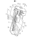
図1は、本発明の一実施形態における液体噴射システム10の斜視図である。図1には、互いに直交するXYZ軸が描かれている。図1のXYZ軸は他の図のXYZ軸に対応している。これ以降に示す図についても必要に応じてXYZ軸を付している。液体噴射システム10は、液体供給ユニットとしてのインクカートリッジ20と、液体噴射装置としてのプリンター50とを備える。
A. First Embodiment FIG. 1 is a perspective view of a
プリンター50は、制御部510と、キャリッジユニット520と、を備える。キャリッジユニット520は、印刷ヘッド540とオンキャリッジ・ホルダー60とを備える。オンキャリッジ・ホルダー60には、利用者(ユーザー)によってインクカートリッジ20が着脱可能に装着される。なお、インクカートリッジ20を「カートリッジ」とも呼ぶ。また、オンキャリッジ・ホルダー60を、「ホルダー」、「ホルダーユニット」又は「カートリッジ装着部」とも呼ぶ。
The
プリンター50の制御部510は、プリンター50の各部を制御する。キャリッジユニット520は、印刷ヘッド540を印刷媒体90に対して相対的に移動可能に構成されている。制御部510とキャリッジユニット520との間はフレキシブルケーブル517を介して電気的に接続されている。印刷ヘッド540は、制御部510からの制御信号に基づいて動作し、紙やラベルなどの印刷媒体90に対してインクを吐出する。これにより、文字、図形、画像などが印刷媒体90に印刷される。
A
本実施形態のプリンター50のように、キャリッジユニット520のホルダー60にインクカートリッジ20が装着されるプリンターは、「オンキャリッジタイプ」とも呼ばれる。他の実施形態では、キャリッジユニット520とは異なる部位に、不動の定置式のカートリッジホルダー(オフキャリッジ・ホルダー)を設置し、そのオフキャリッジ・ホルダーに装着されたインクカートリッジからのインクを、フレキシブルチューブを介してキャリッジユニット520の印刷ヘッド540に供給しても良い。このようなプリンターのタイプは、「オフキャリッジタイプ」とも呼ばれる。
A printer in which the
プリンター50は、キャリッジユニット520と印刷媒体90とを相対的に移動させるための主走査送り機構および副走査送り機構を備える。主走査送り機構は、例えば、キャリッジモーター522および駆動ベルト524を備え、駆動ベルト524を介してキャリッジモーター522の動力をキャリッジユニット520に伝達することによって、キャリッジユニット520を主走査方向に往復移動させる。副走査送り機構は、例えば、搬送モーター532およびプラテン534を備え、搬送モーター532の動力をプラテン534に伝達することによって、主走査方向に直交する副走査方向に印刷媒体90を搬送する。主走査送り機構のキャリッジモーター522および副走査送り機構の搬送モーター532は、制御部510からの制御信号に基づいて動作する。
The
本明細書では、液体噴射システム10の使用状態(「使用姿勢」ともいう)において、キャリッジユニット520を往復移動させる主走査方向(左右方向)に沿った軸をX軸とし、印刷媒体90を搬送する副走査方向(前後方向)に沿った軸をY軸とし、重力方向(上下方向)に沿った軸をZ軸とする。液体噴射システム10の使用状態とは、水平な面に設置された液体噴射システム10の状態であり、水平な面はY軸およびX軸に平行な面(XY平面)である。なお、副走査方向(前方向)を+Y方向、その逆方向(後方向)を−Y方向とし、重力方向の下方から上方に向かう方向(上方向)を+Z方向とし、その逆方向(下方向)を−Z方向とする。液体噴射システム10の+Y方向側(前側)が、液体噴射システム10の正面となる。液体噴射システム10の右側面から左側面に向かう方向を+X方向(左方向)、その逆方向を−X方向(右方向)とする。ホルダー60に装着された複数のカートリッジ20の配列方向は、X軸に沿った方向である。+Z方向を「第1方向」とも呼び、また、+−Y方向を「第2方向」と、−Z方向を「第3方向」とも呼ぶ。
In this specification, in a use state (also referred to as a “use posture”) of the
インクカートリッジ20は、印刷材としてのインクを収容する。カートリッジ20に収容されたインクは、後述するインク供給口及びインク供給管を介して印刷ヘッド540に供給される。ホルダー60には、複数のカートリッジ20が着脱可能に装着される。本実施形態では、6色(ブラック、イエロ、マゼンタ、ライトマゼンタ、シアンおよびライトシアン)のインクに対応して6種類のカートリッジ20が1つずつ、すなわち合計6つのカートリッジ20がホルダー60に装着される。但し、ホルダー60に装着可能なカートリッジ20の数やインクの種類は、任意に設定可能である。カートリッジ20およびホルダー60の詳細構成については後述する。
The
図2及び図3は、インクカートリッジ20の斜視図である。このカートリッジ20は、外殻22と、インク供給口280と、回路基板40と、操作部912と第1係合部914とを含む係合構造910(図3)と、第2係合部220と、突出部260とを備える。第1係合部914と第2係合部220は、カートリッジ20をホルダー60に係合させるための構造である。第1係合部914は可動式の構成を有しており、第2係合部220は非可動式の構成を有している。第2係合部220は、カートリッジ20の外殻22と一体成形されている。一方、係合構造910は、カートリッジ20の外殻22とは別体として形成されている。カートリッジ20をホルダー60に装着する際の装着方向SDは、−Z方向である。なお、外殻22を「カートリッジ本体」とも呼ぶ。また、インク供給口280を「液体供給部」とも呼ぶ。
2 and 3 are perspective views of the
外殻22は、カートリッジ20のインク収容部200(液体収容室)を含む内部空間を区画規定する。また、外殻22はカートリッジ20の外壁面の少なくとも一部を構成する。外殻22はポリプロピレン(PP)等の合成樹脂により形成されている。カートリッジ20は、略角柱形状又は略直方体形状である。なお、外殻22の一部は、樹脂製フィルムにより形成されていても良い。
The
外殻22は、第1壁201と、第2壁202と、第3壁203と、第4壁204と、第5壁205(第6壁の反対側の壁)と、第6壁206と、第7壁207と、第8壁208とを有する。以下の説明において、符号201〜208は、カートリッジの外殻22を構成する壁の外表面(第1〜第8面201〜208)を意味するものとしても利用する。第1面201〜第8面208は、それぞれ概ね平面である。「概ね平面」とは、面全域が完全に平坦である場合と、面の一部に凹凸を有する場合を含む。つまり、面の一部に多少の凹凸があっても、カートリッジ20の外殻を構成する面や壁が把握できるような場合を含む。第1面201〜第8面208の平面視における外形は、いずれも略長方形である。
The
第1面201は、装着状態において底面となる面であり、水平な面となる。すなわち、第1面201は、Y軸及びX軸に平行で、Z軸に垂直な面(XY平面)である。
The
第2面202は、装着状態において上面となる面である。第2面は、第1面201と対向する。また、第2面202は、第1面201に平行な面である。すなわち、第2面202はY軸及びX軸に平行で、Z軸に垂直な面である。第2面202は装着状態において水平な面(XY平面)である。
The
第3面203は、装着状態において正面となる面である。第3面203は、第1面201と第2面202と交差する面である。第3面203はX軸及びZ軸に平行で、Y軸に垂直な面(XZ平面)である。なお、本明細書では、2つの面が「交差する」とは、2つの面が相互に実際に交差する状態と、一方の面の延長面が他方の面に交差する状態と、相互の延長面が交差する状態と、のいずれかの状態であることを意味する。
The
第4面204は、装着状態において背面となる面である。第4面204は、第1面201と第2面202に交差する面である。また、第4面204は、第3面203に平行な面である。第4面204は、X軸及びZ軸に平行で、Y軸に垂直な面(XZ平面)である。
The
第5面205は装着状態において左側面となる面であり、第6面206は装着状態において右側面となる面である。第5面205と第6面206は、それぞれ、第1〜第4面201〜204に交差する面である。第5面205と第6面206は、Y軸及びZ軸に平行で、X軸に垂直な面(YZ平面)である。また、第6面206は、第5面205に平行な面である。
The
第7面207と第8面208は、第1面201と第3面203とを繋ぐ面である。第7面207は、第1面201と交差する面である。第7面207は、X軸及びZ軸に平行な面(XZ平面)である。段差面としての第7面207は、第1面201に対し立設された面である。すなわち、第7面207は第1面201から+Z方向に延びる面である。また、第7面207は第8面208に対して−Y方向側かつ−Z方向側に位置する。第8面208は、第7面207と第3面203とを繋ぐ面である。第8面208は+Y方向と−Z方向の成分を含む方向を向いて傾斜した斜面である。第8面208は、第1面201及び第3面203に対して傾斜した面である。第8面208は、第5面205及び第6面206と交差する面である。第8面208は、XY平面及びXZ平面に対して傾斜しており、YZ平面に対して直角に交差する。第8面208の法線ベクトルは、+Y方向成分と−Z方向成分とに分解可能である。
The
回路基板40は、第8面208に設置されている。回路基板40の表面408の法線ベクトルも、第8面と同様に、+Y方向成分と−Z方向成分とに分解可能である。表面408は、第1面201及び第3面203に対して傾斜した面である。表面408は、第5面205及び第6面206と交差する面である。表面408は、XY平面及びXZ平面に対して傾斜しており、YZ平面に対して直角に交差する。表面408を「傾斜面408」と呼ぶことも可能である。表面408には、カートリッジ側電気端子群400が設けられている。回路基板40の裏側には、例えば記憶装置などの電気デバイス(図示省略)が設けられている。この電気デバイスは、カートリッジ側電気端子群400と配線で接続されている。例えば、記憶装置には、カートリッジ20のインクに関する情報(インク残量やインク色)等が格納される。回路基板40を「電気端子部40」とも呼ぶ。
The
インク供給口280は、第1面201から−Z方向側に突出して設けられている。インク供給口280にはプリンター50のインク供給管(後述)が接続され、カートリッジ20内のインクを印刷ヘッド540に流通させる。すなわち、インク供給口280は外部に向かって開口し、カートリッジ20のインクを外部に流通させる。また、インク供給口280は、第1面201のうち第3面203よりも第4面204に近い部分に設けられている。すなわち、Y方向について、インク供給口280の外表面と第3面203との距離は、インク供給口280の外表面と第4面204との距離よりも大きい。
The
インク供給口280の先端は、開口している。この開口によって形成される面(開口面)288は、装着状態において水平な面である。すなわち、開口面288はY軸及びX軸に平行な面(XY平面)である。カートリッジ20の工場出荷時は、インク供給口280の開口面288は、キャップまたはフィルムなどの封止部材(図示せず)で封止されている。開口面288を封止する封止部材(図示せず)は、ホルダー60にカートリッジ20を装着する前にカートリッジ20から取り外される。
The tip of the
第1係合部914は、カートリッジ20の第3面203から+Y方向に突出する。この第1係合部914は、+−Y方向に沿ってスライド可能に構成されている。第1実施形態では、利用者が操作部912を−Y方向に移動させると、これに応じて第1係合部914が−Y方向にスライドする。第1係合部914は、カートリッジ20がホルダー60に装着された状態で、ホルダー60内の装置側第1係合部(後述)と係合することによって、カートリッジ20が+Z方向に移動する動きを規制する。操作部912と第1係合部914を含む係合構造910の詳細及びその動作については後述する。
The first
カートリッジ20は、さらに、第4面204に設けられた第2係合部220を有する。第2係合部220は、第4面204から−Y方向側に突出するように設けられた突起である。第2係合部220は、カートリッジ20がホルダー60に装着された状態で、ホルダー60内の装置側第2係合部(後述)と係合することによって、カートリッジ20が+Z方向に移動する動きを規制する機能を有する。
The
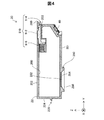
図4は、カートリッジ20の要部断面図である。カートリッジ20のインク収容部200は、インク流通孔282を介してインク供給口280と連通している。インク供給口280には、発泡体樹脂284が配置されている。
FIG. 4 is a sectional view of an essential part of the
係合構造910は、操作部912及び第1係合部914の他に、付勢部916を有している。付勢部916は、操作部912と第1係合部914を+Y方向に付勢する。この例では、付勢部916は、金属製のバネである。付勢部916は、Y方向においてインク供給口280と回路基板40との間に位置することが好ましい。こうすれば、付勢部916が変形して十分な付勢力を発生するのに十分な大きさを確保することができる。但し、付勢部916は省略してもよい。
The
第1係合部914は、Y方向に延びる平板状部材であり、+−Y方向にスライド可能に構成されている。この例では、操作部912と第1係合部914は同一部材で一体成形されている。従って、少ない部品点数で操作部912と第1係合部914とを含む係合構造910を実装することが可能である。但し、操作部912と第1係合部914を別体で形成し、これらを付勢部916と組合せて係合構造910を構成してもよい。第1係合部914は、付勢部916によって+Y方向に付勢されているので、カートリッジ20の未使用状態において、第1係合部914はその移動可能範囲の中で最も+Y方向に進んだ位置にある。但し、図4では、操作部912及び第1係合部914が−Y方向に移動した後の状態を示している。操作部912と第1係合部914は、回路基板40を+Z方向に投影した位置に配置されていることが好ましい。こうすれば、回路基板40の近傍に第1係合部914が位置するので、回路基板40とホルダー60の装置側端子との間の電気的接触を安定化することが可能である。
The first
操作部912は、利用者が第1係合部914を−Y方向に移動させる際に利用される。この例では、操作部912は、多数の凹凸を表面に有する部材である。操作部912の凹凸は、カートリッジ20の第2面202に設けられた開口部から露出している。この操作部912に利用者の指を押し当てつつ−Y方向に操作部912を移動させると、これに応じて第1係合部914が−Y方向に移動する。操作部912は、カートリッジ20の第2面202に露出した状態で設けられているので、利用者が容易に操作可能である。さらに、操作部912は、第1係合部914と第2係合部220との間に位置することが好ましい。こうすれば、操作部912の両側にある2つの係合部914,220でカートリッジ20がホルダー60に係合された状態で操作部912を操作できる。従って、カートリッジ20の姿勢が安定した状態で操作部912を操作することが可能である。
The
図5は、オンキャリッジ・ホルダー60の斜視図であり、図6は、その要部断面図である。ホルダー60は、カートリッジ20を受け入れる凹形状のカートリッジ収容室602を規定する壁面として、5つの壁部601,603,604,605,606を有する。5つの壁部601,603,604,605,606をまとめて、「収容室形成壁部600」と呼ぶ。本実施形態では、5つの壁部601,603,604,605,606は、合成樹脂製の板状部材で形成されている。
FIG. 5 is a perspective view of the on-
壁部601は凹形状のカートリッジ収容室602の底面を規定する。壁部603,604,605,606はそれぞれ、凹形状のカートリッジ収容室602の側面を規定する。壁部601を「装置側底壁部601」とも呼び、また、壁部603を「第1の装置側側壁部603」と、壁部604を「第2の装置側側壁部604」と、壁部605を「第3の装置側側壁部605」と、壁部606を「第4の装置側側壁部606」とも呼ぶ。
The
壁部601上には、Y方向に沿って、インク供給管640と、装置型端子群を備えた接点機構70とが配列されている。インク供給管640は、壁部603よりも壁部604に近い側に設けられている。接点機構70は、インク供給管640よりも壁部603に近い側に設置されている。
On the
壁部601のうちのインク供給管640の周囲には、弾性部材648が設けられている。弾性部材648は、カートリッジ20がホルダー60に装着された状態でカートリッジ20のインク供給口280の周囲を密閉することによって、インク供給口280から周囲へのインクの漏出を防止する。また、弾性部材648は、カートリッジ20がホルダー60に装着された状態で、カートリッジ20のインク供給口280を押し返す方向(+Z方向)に付勢力を発生させる。
An
壁部603は、ホルダー60の正面を構成する。壁部603には、装置側第1係合部660が設けられている。装置側第1係合部660は、カートリッジ20の第1係合部914と係合する部材である。図6に示すように、装置側第1係合部660は、接点機構70を+Z方向に投影した位置にあることが好ましい。装置側第1係合部660は、カートリッジ20の第1係合部914が挿入される係合凹部662を有している。この係合凹部662は、第1係合部914と装置側第1係合部660との係合箇所に相当する。
The
壁部604は、ホルダー60の背面を構成する。壁部604には、装置側第2係合部620が設けられている。装置側第2係合部620は、カートリッジ20の第2係合部220と係合する部材である。この例では、装置側第2係合部620は壁部604をY方向に貫通する貫通孔である。なお、装置側第2係合部620は、カートリッジ収容室602を向いて開口した凹部であっても良い。壁部605は、ホルダー60の右側面を構成する。壁部606は、ホルダー60の左側面を構成する。
The
ホルダー60の壁部601と壁部603とが交差するコーナー部には、接点機構70が設けられている。接点機構70は、インク供給管640よりも壁部603側に設置されている。図6に示すように、接点機構70は、カートリッジ20の回路基板40(図2)の複数の電気端子に対応して接触する複数の装置側電気端子700と、複数の装置側電気端子700を保持する端子台709とを有する。装置側電気端子700は、端子台709の傾斜面708から突出している。装置側電気端子700は、カートリッジ20がホルダー60に装着された状態で、カートリッジ20の回路基板40を押し返す方向(+Z方向と−Y方向の成分を含む方向)に付勢力を発生させる。この付勢力の方向は、端子台709の傾斜面708に略垂直な方向である。すなわち、傾斜面708から突出している装置側電気端子700がカートリッジ20によって傾斜面708側に押し込まれると、その反力として、斜め方向の付勢力をカートリッジ20に与える。
A
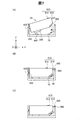
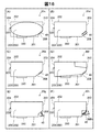
図7は、カートリッジ20をホルダー60に装着する様子を示す説明図である。ここでは、カートリッジ20とホルダー60の外形を簡略化して描いている。ホルダー60内にカートリッジ20を装着する際には、図7(A)に示すように、カートリッジ20の後端側(−Y方向の端部)をやや下げた斜めの姿勢でカートリッジ20をホルダー60内に進入させる。そして、第4面204に形成された第2係合部220としての突起を、ホルダー60の装置側第2係合部620としての貫通孔に挿入する。この第2係合部220と装置側第2係合部620の係合によって、カートリッジ20の後端側の+Z方向への移動が規制される。その後、利用者が、操作部912を操作して第1係合部914を−Y方向に退避させた状態でカートリッジ20の前端側を下降させると、図7(B)の状態となる。そして、利用者が操作部912を解放する(すなわち操作部912から指を離す)と、付勢部916(図4)によって第1係合部914が+Y方向に押し戻される。この結果、図7(C)に示すように、第1係合部914が装置側第1係合部660の係合凹部662に進入する。この状態では、第1係合部914と第2係合部220の2つの係合部によって、カートリッジ20の+Z方向への移動が規制される。
FIG. 7 is an explanatory view showing how the
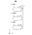
図8は、図7における第1係合部914のY方向に沿った位置の変化を示す説明図である。カートリッジ20をホルダー60に装着する前の状態(利用者が操作部912に触れていない状態)では、第1係合部914の先端は、図8(A)に示す第1位置Aにある。第1位置Aは、第1係合部914の先端の移動可能範囲の中で+Y方向側の最端部にある。図7(B)に示した装着途中の状態では、第1係合部914の先端は、図8(B)に示す第2位置Bにある。第2位置Bは、第1位置Aよりも−Y方向に戻った位置にある。図7(C)に示した装着後の状態では、第1係合部914の先端は、図8(C)に示す第3位置cにある。第3位置Cは、第2位置Bよりも+Y方向に進んだ位置である。なお、第3位置Cは、第1位置Aと第2位置Bの間の位置であってもよく、或いは、第1位置Aと同じ位置であってもよい。このように、利用者が操作部912を用いて第1係合部914を+−Y方向にスライドさせることによって、第1係合部914をホルダー60の装置側第1係合部660に容易に係合させることができる。
FIG. 8 is an explanatory view showing a change in the position of the first engaging
図9は、カートリッジ20がホルダー60に装着された状態を示す要部断面図である。この図は、図7(C)に示した状態に相当する。カートリッジ20がホルダー60内に装着された状態では、カートリッジ20のインク供給口280がホルダー60のインク供給管640の周囲の弾性部材648から+Z方向の付勢力Psを受ける。また、カートリッジ20の回路基板40は、接点機構70から斜め方向の付勢力Ptを受ける。この付勢力Ptは、+Z方向成分を有するので、インク供給口280が受ける付勢力Psとともに、カートリッジ20を+Z方向(「第1方向」)に付勢する力として働く。カートリッジ20の第1係合部914と第2係合部220は、これらの付勢力Ps,Ptに抗して、カートリッジ20をホルダー60内で安定した状態で固定する機能を有する。ここで、「安定した状態」とは、インク供給口280とインク供給管640とが漏れの無い連通状態にあること、及び、回路基板40と接点機構70との間の電気的接続が安定していること、を意味する。なお、回路基板40は、第1係合部914とホルダー60との係合箇所(係合凹部662)と、インク供給口280との間に位置している。従って、第1係合部914は、インク供給口280よりも回路基板40に近いので、回路基板40と接点機構70との間の電気的接続を安定させる機能を有する。
FIG. 9 is a cross-sectional view of an essential part showing a state in which the
以上のように、第1実施形態では、カートリッジ20がホルダー60から上方(+Z方向)に移動する動きを規制可能な第1係合部914をカートリッジ20の前面である第3面203に設けたので、従来とは異なる構造を用いてカートリッジ20をホルダー60に係合させることが可能である。また、第1係合部914とホルダー60との係合を解除可能な操作部912をカートリッジ20に設けたので、従来技術に無い新たな係合機構によってカートリッジ20をホルダー60から取り外すことが可能である。
As described above, in the first embodiment, the first engaging
B.第2実施形態
図10(A)は、第2実施形態におけるカートリッジ20aの要部断面図であり、第1実施形態の図4に対応する図である。第1実施形態との違いは、第1係合部914と操作部912を含む係合構造910aの構成が異なる点である。カートリッジ20aの他の構造は、図2に示した第1実施形態とほぼ同じなのでそれらの説明は省略する。
B. Second Embodiment FIG. 10A is a cross-sectional view of an essential part of a
この係合構造910aは、+−Y方向にスライド移動可能な第1係合部914と、利用者が操作する操作部912と、付勢部917とを有している。この例では、第1係合部914と操作部912と付勢部917は、一体成形されている。また、係合構造910aは、カートリッジ20aの外殻22aとは別体として形成されている。図10(A)は、利用者が操作部912を−Y方向に移動させた状態を示しており、図10(B)は、利用者が操作部912を解放した状態を示している。係合構造910aの付勢部917は、第1係合部914及び操作部912を+Y方向に付勢する。このような付勢力を発生させるために、係合構造910aは弾性のある樹脂等で形成されていることが好ましい。この第2実施形態も、上述した第1実施形態と同様の効果を奏する。また、第2実施形態では、第1係合部914と操作部912と付勢部917とが一体成形されているので、第1実施形態よりもさらに部品点数を削減することが可能である。
The
C.第3実施形態
図11は、第3実施形態におけるカートリッジ20bの要部断面図であり、第2実施形態の図10に対応する図である。第2実施形態との違いは、第1係合部914と操作部912と付勢部917とを含む係合構造910bが、カートリッジ20bの外殻22bと一体成形されている点である。カートリッジ20bの他の構造は、図2に示した第1実施形態とほぼ同じなのでそれらの説明は省略する。
C. Third Embodiment FIG. 11 is a cross-sectional view of an essential part of a
この第3実施形態も、上述した第1実施形態及び第2実施形態と同様の効果を奏する。また、第3実施形態では、第1係合部914と操作部912と付勢部917が、カートリッジ20bの外殻22bと一体成形されているので、第2実施形態よりもさらに部品点数を削減することが可能である。
The third embodiment also exhibits the same effects as those of the first and second embodiments described above. Further, in the third embodiment, since the
D.第4実施形態
図12は、第4実施形態においてカートリッジ20がホルダー60aに装着された状態を示す要部断面図であり、第1実施形態の図9に対応する図である。第1実施形態との違いは、ホルダー60aの装置側第1係合部80の構成である。ホルダー60aの他の部分の構成は第1実施形態とほぼ同じであり、また、カートリッジ20の構成は第1実施形態と同一なので、それらの説明は省略する。
D. Fourth Embodiment FIG. 12 is a cross-sectional view of relevant parts showing a state in which the
装置側第1係合部80は、ホルダー60aの第3壁603の近傍に設けられたレバーとして形成されている。装置側第1係合部80の頭部の内側(−Y方向側)には、凹部810が形成されている。この凹部810には、カートリッジ20の第1係合部914が進入可能である。装置側第1係合部80は、回動軸800cを中心に回動可能に設置されている。すなわち、装置側第1係合部80の頭部の外面830(+Y方向側の面)を利用者が−Y方向に押すと、装置側第1係合部80が軸800cを中心として反時計回りに回動する。図12は、装置側第1係合部80の外面830が押されていない状態を示している。この状態では、仮に、装置側第1係合部80が第1係合部914によって+Y方向に押されたとしても、装置側第1係合部80は回動せずにそのままの姿勢で維持される。従って、この装置側第1係合部80も、図6及び図9に示した第1実施形態の装置側第1係合部660とほぼ同様に、カートリッジ20の第1係合部914と係合する機能を発揮することが可能である。このようなホルダー60aは、上述した第2実施形態や第3実施形態のカートリッジとともに使用することも可能である。この第4実施形態も、上述した第1〜第3実施形態と同様の効果を奏する。
The device-side
E.第5実施形態
図13は、第5実施形態におけるカートリッジ20mの要部断面図であり、第1実施形態の図4に対応する図である。第1実施形態との違いは、係合構造910dの構成が異なる点である。カートリッジ20mの他の構造は、図2に示した第1実施形態とほぼ同じなのでそれらの説明は省略する。
E. Fifth Embodiment FIG. 13 is a cross-sectional view of an essential part of a
この係合構造910dは、付勢部916を含まず、操作部912及び第1係合部914の他に、第2壁202に向かって+Z方向に突出する第1係合突起920を有する。そして、第2壁202は、係合構造910dに向かって−Z方向に突出する第2係合突起261を有する。利用者が操作部912を操作し、第1係合部914を+Y方向に移動させたとき、第1係合突起920が第2係合突起261に当接する。そして係合構造910dまたは第2壁202が一時的に弾性変形することで、第1係合突起920が第2係合突起261と第3壁203との間に移動する。この結果、カートリッジ20mがホルダー60に係合される。
The
図14は、第5実施形態においてカートリッジ20mがホルダー60に装着された状態を示す要部断面図であり、第1実施形態の図9に相当する図である。この装着状態では、第1係合突起920と第2係合突起261とが係合した状態で、係合構造910dがカートリッジ20mの外殻22に固定される。これにより、係合構造910dの−Y方向への移動が規制されて、第3壁203から+Y方向に突出した第1係合部914と装置側第1係合部660との係合状態が維持される。この第5実施形態からも理解できるように、係合構造910は付勢部材を有していなくても良い。但し、係合構造910が第1係合部914を付勢する付勢部材を有するようにすれば、第1係合部914とホルダー60との係合状態を確実に維持することが容易になるという利点がある。
FIG. 14 is a cross-sectional view of relevant parts showing a state in which the
F.カートリッジの他の実施形態
図15は、他の実施形態におけるカートリッジの構成を示す説明図である。なお、図15では、説明の便宜上、個々の部材の形状が簡略化して描かれている。
F. Another Embodiment of Cartridge FIG. 15 is an explanatory view showing a configuration of the cartridge in another embodiment. In addition, in FIG. 15, the shape of each member is simplified and drawn for convenience of explanation.
図15(A)に示すカートリッジは、図4に示した第1実施形態のカートリッジ20と同様の係合構造910を有している。すなわち、この係合構造910は、第1係合部914と操作部912と付勢部916とを含んでおり、第1係合部914と操作部912は一体形成されており、付勢部916は別体のバネで形成されている。但し、図15(A)のカートリッジでは、インクを収容する構造が図4と異なっている。すなわち、カートリッジの第4面204と回路基板40との間には、インク貯蔵室242とインク供給室244とが区画されている。インク貯蔵室242とインク供給室244とを合わせて「液体収容室」とも呼ぶ。カートリッジの第2面202のうちのインク貯蔵室242の上方の位置には、インク注入口241が形成されている。但し、このインク注入口241は、カートリッジ20の使用時にはシール材等でシールされる。第2面202のうちのインク供給室244の上方の位置には、大気孔243が形成されている。インク供給室244内には多孔性のインク保持部材246が収納される。インク供給室244は、インク流通孔282を介してインク供給口280と連通している。
The cartridge shown in FIG. 15A has an
図15(B)に示すカートリッジは、図15(A)に示した構造と同じ液体収容室(インク貯蔵室242及びインク供給室244)を有し、また、図10に示した第2実施形態のカートリッジ20aと同様の係合構造910aを有している。すなわち、この係合構造910aの第1係合部914と操作部912と付勢部917は一体成形されている。また、係合構造910aは、カートリッジの外殻とは別体として形成されている。
The cartridge shown in FIG. 15 (B) has the same liquid storage chamber (
図15(C)に示すカートリッジは、図15(A)に示した構造と同じ液体収容室(インク貯蔵室242及びインク供給室244)を有し、また、図11に示した第3実施形態のカートリッジ20bと同様の係合構造910bを有している。すなわち、この係合構造910bの第1係合部914と操作部912と付勢部917は、カートリッジの外殻と一体成形されている。
The cartridge shown in FIG. 15C has the same liquid storage chamber (
図15(D)に示すカートリッジは、図15(A)に示した構造と同じ液体収容室(インク貯蔵室242及びインク供給室244)を有しているが、係合構造910cは他の実施形態と若干異なっている。すなわち、この係合構造910cの第1係合部914と操作部912は、一体成形されている。付勢部918は、板バネで別体に形成されている。付勢部918は、液体収容室(より正確にはインク供給室244)に隣接して設けられた収容室248に収容されている。この係合構造910cは、図15(A)に示す係合構造910と似ているが、第1係合部914のZ方向の位置が、図15(A)よりも−Z方向側にあり、カートリッジの高さの1/2以下の範囲に存在する点が異なる。なお、「カートリッジの高さ」とは、Z方向における第1面201と第2面202の最大距離を意味する。この係合構造910cは、第1係合部914のZ方向の位置が図15(A)に比べてより低い位置にあるので、回路基板40の接続状態をより安定化させることが可能である。
Although the cartridge shown in FIG. 15D has the same liquid storage chamber (
図15(A)〜(D)から理解できるように、カートリッジの液体収容室や、係合構造910の構成としては、種々の変形が可能である。これらの変形例においても、上述した第1〜第4実施形態とほぼ同様の効果を奏することができる。
As can be understood from FIGS. 15A to 15D, various modifications can be made to the configuration of the liquid storage chamber of the cartridge and the
なお、図15の変形例からも理解できるように、操作部912は、カートリッジの第2面202に設けられている必要は無いが、少なくとも第2面202に露出していることが好ましい。ここで、「操作部912が第2面202に露出している」という語句は、(i)操作部912が第2面202に設けられている場合と、(ii)操作部912が第2面202に設けられている訳ではないが操作部912の一部が第2面202に露出している場合と、を含む意味で使用される。
As can be understood from the modified example of FIG. 15, the
図16は、他の実施形態におけるカートリッジの形状を示す概念図である。但し、図16では、図示の便宜上、係合構造910の図示を省略している。図16(A)に示すカートリッジ20cの外殻22cは、楕円形又は長円形の側面を有している。また、カートリッジ20cは、その正面側に回路基板40を有する。また、カートリッジ20cの底面側には、インク供給口280が形成されており、背面側には第2係合部220が形成されている。なお、このカートリッジ20cを正面側から見ると、一定の幅を有している。このカートリッジ20cも、回路基板40とインク供給口280とが、プリンター50の対応する部材と接続するように構成されていれば、上述した各実施形態のカートリッジ20,20aと互換性を確保することが可能である。
FIG. 16 is a conceptual view showing the shape of the cartridge in another embodiment. However, in FIG. 16, for convenience of illustration, the
図16(B)に示すカートリッジ20dは、図2や図15と同様に略直方体形状を有している。図2のカートリッジ20との大きな差異は、第8面208が、第3面203の下端に連続して設けられていない点である。図16(C)及び図16(D)に示すカートリッジ20e,20fは第7面を有さない点で図2のカートリッジ20と異なる。図16(E)に示すカートリッジ20gでは、回路基板40が、第8面208にバネを介して取り付けられている。図16(F)に示すカートリッジ20hでは、第8面208に相当する面208hが可動となっており、この面208hに回路基板40が設けられている。これらのカートリッジ20c〜20gにおいても、回路基板40とインク供給口280とがプリンター50の対応する部材と接続するように構成されており、上述した各実施形態のカートリッジ20,20aと互換性を確保することが可能である。
The
図16に示した各種の例から理解できるように、カートリッジの外形の形状には、様々な変形例が考えられる。カートリッジの外形の形状が略直方体以外の形状を有している場合にも、例えば図16(A)及び(D)に点線で示したように、略直方体の6つの面、すなわち、図2に示した底面201(第1面)、上面202(第2面)、正面203(第3面)、背面204(第4面)、左側面205(第5面)、及び右側面206(第6面)、を仮想的に考えることが可能である。本明細書において、「面」(プレーン)という用語は、このような仮想的な面(仮想面、非実在面とも呼ぶ)と、図2に記載したような実在面と、の両方を包含した意味で使用することができる。また、「面」という用語は、平面と曲面の両方を包含した意味で使用される。 As can be understood from the various examples shown in FIG. 16, various modifications can be considered for the shape of the outer shape of the cartridge. Even when the external shape of the cartridge has a shape other than a substantially rectangular parallelepiped, for example, as shown by dotted lines in FIGS. 16A and 16D, six sides of the substantially rectangular parallelepiped, ie, FIG. Bottom surface 201 (first surface), top surface 202 (second surface), front surface 203 (third surface), back surface 204 (fourth surface), left surface 205 (fifth surface), and right surface 206 (sixth surface) It is possible to virtually consider In the present specification, the term "plane" (plane) includes both such virtual plane (also referred to as virtual plane or non-real plane) and real plane as described in FIG. Can be used in the sense. Also, the term "surface" is used in a sense that includes both flat and curved surfaces.
・変形例:
なお、この発明は上記の実施例や実施形態に限られるものではなく、その要旨を逸脱しない範囲において種々の態様において実施することが可能であり、例えば次のような変形も可能である。
・ Modification:
The present invention is not limited to the above embodiments and embodiments, and can be implemented in various modes without departing from the scope of the invention. For example, the following modifications can be made.
・変形例1:
上記各実施形態における係合構造910,910a〜910dの各部材の形状や構造は一例であり、これら以外の他の種々の形状や構造を有する係合構造を利用可能である。この場合にも、カートリッジの係合構造は、カートリッジがホルダー60内で第1面201から第2面202に向かう方向(+Z方向)に移動する動きを規制可能な構成を有していることが好ましく、特に、第1係合部914が第3面203から+Y方向に突出していることが好ましい。また、係合構造910,910a〜910cの付勢部916〜918は、省略してもよい。但し、付勢部を設けるようにすれば、第1係合部914とホルダー60との係合をより確実なものとすることができる。
Modification 1:
The shapes and structures of the members of the engaging
・変形例2:
上述した各実施形態及び各変形例において、係合構造910,910a〜910c以外の構成や部材も、目的や用途に応じて適宜変更したり省略したりすることが可能である。例えば、上記各実施形態及び各変形例では、第2係合部220をカートリッジ20の第4面204に設けていたが、第2係合部220を他の面(例えば第1面201や第2面202)に設けてもよい。また、第2係合部220を省略してもよい。但し、第2係合部220を設けるようにすれば、第1係合部914と第2係合部220との両方を用いて、カートリッジ20をより確実にホルダー60に係合させることが可能である。また、上述した各実施形態及び各変形例において、回路基板40(電気端子部)を省略してもよい。
・ Modified example 2:
In each embodiment and each modification which were mentioned above, it is possible to change suitably and to omit composition and members other than
・変形例3:
上述した各実施形態及び各変形例のカートリッジの構成は、インク収容室(液体収容室)を有するインク収容室形成部材と、アダプターとに分離することも可能である。インク収容室部材とアダプターは、組み合わせた状態でホルダー60に装着される。この場合には、第1係合部914を含む係合構造910(又は910a〜910c)と第2係合部220の少なくとも一方を、アダプターに設けることが好ましい。本明細書では、インク収容室部材とアダプターとに分離された構成も、「インク供給ユニット」又は「液体供給ユニット」という用語に包含されている。
Modified Example 3:
The configuration of the cartridge of each embodiment and each modification described above can be separated into an ink storage chamber forming member having an ink storage chamber (liquid storage chamber) and an adapter. The ink storage chamber member and the adapter are mounted on the
・変形例4:
本発明は、インクジェットプリンター及びそのインクカートリッジに限らず、インク以外の他の液体を噴射する任意の液体噴射装置及びそのホルダーに装着される液体供給ユニットにも適用することができる。例えば、以下のような各種の液体噴射装置及びそのホルダーに装着される液体供給ユニットに適用可能である。
(1)ファクシミリ装置等の画像記録装置
(2)液晶ディスプレイ等の画像表示装置用のカラーフィルタの製造に用いられる色材噴射装置
(3)有機EL(Electro Luminescence)ディスプレイや、面発光ディスプレイ (Field Emission Display、FED)等の電極形成に用いられる電極材噴射装置
(4)バイオチップ製造に用いられる生体有機物を含む液体を噴射する液体噴射装置
(5)精密ピペットとしての試料噴射装置
(6)潤滑油の噴射装置
(7)樹脂液の噴射装置
(8)時計やカメラ等の精密機械にピンポイントで潤滑油を噴射する液体噴射装置
(9)光通信素子等に用いられる微小半球レンズ(光学レンズ)などを形成するために紫外線硬化樹脂液等の透明樹脂液を基板上に噴射する液体噴射装置
(10)基板などをエッチングするために酸性又はアルカリ性のエッチング液を噴射する液体噴射装置
(11)他の任意の微小量の液滴を吐出させる液体噴射ヘッドを備える液体噴射装置
Modification 4:
The present invention is applicable not only to an ink jet printer and its ink cartridge, but also to any liquid ejecting apparatus that ejects liquid other than ink and a liquid supply unit attached to its holder. For example, the present invention is applicable to various liquid ejecting apparatuses as described below and a liquid supply unit attached to the holder thereof.
(1) Image recording apparatus such as facsimile apparatus (2) Color material injection apparatus used for manufacturing color filters for image display apparatus such as liquid crystal display (3) Organic EL (Electro Luminescence) display, surface emitting display (Field Electrode material jet device used for electrode formation such as emission display (FED) (4) Liquid jet device for jetting liquid containing bioorganic matter used for biochip manufacturing (5) Sample jet device as precision pipette (6) Lubrication Oil injection device (7) Resin liquid injection device (8) Liquid injection device that injects lubricating oil at precision points such as watches and cameras (9) Micro-hemispherical lenses used for optical communication elements etc. (optical lens A liquid jet apparatus (10) which ejects a transparent resin liquid such as an ultraviolet curable resin liquid onto a substrate to form a substrate etc. A liquid ejecting apparatus that ejects alkaline of the etching solution (11) any other liquid ejecting apparatus including a liquid ejecting head ejecting a minute amount of liquid droplet
なお、「液滴」とは、液体噴射装置から吐出される液体の状態をいい、粒状、涙状、糸状に尾を引くものも含むものとする。また、ここでいう「液体」とは、液体噴射装置が噴射させることができるような材料であれば良い。例えば、「液体」は、物質が液相であるときの状態の材料であれば良く、粘性の高い又は低い液状態の材料、及び、ゾル、ゲル水、その他の無機溶剤、有機溶剤、溶液、液状樹脂、液状金属(金属融液)のような液状態の材料も「液体」に含まれる。また、物質の一状態としての液体のみならず、顔料や金属粒子などの固形物からなる機能材料の粒子が溶媒に溶解、分散または混合されたものなども「液体」に含まれる。また、液体の代表的な例としては上記実施形態で説明したようなインクや液晶等が挙げられる。ここで、インクとは一般的な水性インクおよび油性インク並びにジェルインク、ホットメルトインク等の各種の液体状組成物を包含するものとする。 The “droplet” refers to the state of the liquid discharged from the liquid ejecting apparatus, and includes granular, teardrop-like, and threadlike tails. Further, the “liquid” referred to here may be any material that can be ejected by the liquid ejecting apparatus. For example, the “liquid” may be any material in the liquid phase when the substance is in the liquid phase, and is a liquid material in high or low viscosity, sol, gel water, other inorganic solvents, organic solvents, solutions, Materials in a liquid state such as liquid resin and liquid metal (metal melt) are also included in the “liquid”. Moreover, not only the liquid as one state of the substance, but also those obtained by dissolving, dispersing or mixing particles of functional materials consisting of solid matter such as pigment and metal particles in a solvent are included in the “liquid”. In addition, typical examples of the liquid include the ink described in the above embodiment, liquid crystal, and the like. Here, the ink includes general aqueous inks and oil-based inks, and various liquid compositions such as gel inks and hot melt inks.
以上、いくつかの実施例に基づいて本発明の実施の形態について説明してきたが、上記した発明の実施の形態は、本発明の理解を容易にするためのものであり、本発明を限定するものではない。本発明は、その趣旨並びに特許請求の範囲を逸脱することなく、変更、改良され得るとともに、本発明にはその等価物が含まれることはもちろんである。 Although the embodiments of the present invention have been described above based on several embodiments, the above-described embodiments of the present invention are for the purpose of facilitating the understanding of the present invention, and the present invention is limited. It is not a thing. The present invention can be modified and improved without departing from the spirit and the scope of the claims, and the present invention naturally includes the equivalents thereof.
10…液体噴射システム
20,20a〜20h…インクカートリッジ(カートリッジ)
22,22a〜22c…外殻
40…回路基板(電気端子部)
50…プリンター
60,60a…ホルダー
70…接点機構
80…装置側第1係合部
90…印刷媒体
200…インク収容部
201〜208…第1〜第8面
220…第2係合部
241…インク注入口
242…インク貯蔵室
243…大気孔
244…インク供給室
246…インク保持部材
248…収容室
260…突出部
261…第2係合突起
280…インク供給口
282…インク流通孔
284…発泡体樹脂
288…開口面
400…カートリッジ側電気端子群
408…傾斜面
510…制御部
517…フレキシブルケーブル
520…キャリッジユニット
522…キャリッジモーター
524…駆動ベルト
532…搬送モーター
534…プラテン
540…印刷ヘッド
600…収容室形成壁部
601…装置側底壁部
602…カートリッジ収容室
603…第1の装置側側壁部
604…第2の装置側側壁部
605…第3の装置側側壁部
606…第4の装置側側壁部
620…装置側第2係合部
640…インク供給管
648…弾性部材
660…装置側第1係合部
662…係合凹部
700…装置側電気端子
708…傾斜面
709…端子台
800c…回動軸
810…凹部
830…外面
910,910a〜910c…係合構造
912…操作部
914…第1係合部
916〜918…付勢部
920…第1係合突起
10:
22, 22a to 22c: Outer shell 40: circuit board (electrical terminal portion)
DESCRIPTION OF
Claims (6)
液体供給部が設けられた第1面と、前記第1面に対向する第2面と、前記第1面と前記第2面とに交差する第3面と、前記第1面と前記第2面とに交差し前記第3面に対向する第4面と、を備えた外殻と、
前記外殻とは別体として形成された係合構造と、
を備え、
前記第1面と前記第3面との交差の状態は、前記第1面と前記第3面の一方の面の延長面が他方の面に交わる第1状態と、前記第1面と前記第3面の相互の延長面が互いに交わる第2状態と、のうちのいずれかであり、
前記係合構造は、
前記第4面から前記第3面に向かう+Y方向及び前記+Y方向とは逆の−Y方向に移動可能に構成され、前記液体供給ユニットが前記ホルダーに装着された状態において、前記液体供給ユニットが前記ホルダーから前記第1面から前記第2面に向かう+Z方向に移動する動きを規制可能な第1係合部と、
前記第2面から露出し、前記第1係合部の移動を操作可能な操作部と、を備え、
前記液体供給ユニットは、さらに、
前記第1係合部を前記+Y方向に付勢する付勢部と、
前記第1面と前記第3面との間に配置される電気端子部と、
を備え、
前記付勢部は前記−Y方向において前記液体供給部と前記電気端子部との間に位置する、ことを特徴とする液体供給ユニット。 A liquid supply unit attached to a holder of the liquid ejecting apparatus, the liquid supply unit comprising:
A first surface provided with a liquid supply unit, a second surface facing the first surface, a third surface intersecting the first surface and the second surface, the first surface, and the second surface An outer shell provided with a fourth surface intersecting the surface and facing the third surface;
An engaging structure formed separately from the shell;
Equipped with
In the state of intersection between the first surface and the third surface, a first state in which the extension surface of one surface of the first surface and the third surface intersects the other surface, the first surface and the third surface One of the second states in which the three mutually extending surfaces intersect with each other,
The engagement structure is
The liquid supply unit is configured to be movable in the + Y direction from the fourth surface to the third surface and in the −Y direction opposite to the + Y direction, and in a state where the liquid supply unit is mounted to the holder A first engagement portion capable of restricting movement from the holder to the + Z direction from the first surface to the second surface;
An operation unit exposed from the second surface and capable of operating the movement of the first engagement unit ;
The liquid supply unit further comprises
A biasing portion for biasing the first engagement portion in the + Y direction;
An electrical terminal portion disposed between the first surface and the third surface;
Equipped with
The liquid supply unit according to claim 1, wherein the biasing unit is located between the liquid supply unit and the electric terminal unit in the -Y direction .
前記第4面から突出し、前記液体供給ユニットが前記ホルダーに装着された状態において、前記液体供給ユニットが前記+Z方向に移動する動きを規制可能な第2係合部、を備えることを特徴とする液体供給ユニット。 In the liquid supply unit according to claim 1 , further,
A second engaging portion is provided, which protrudes from the fourth surface and is capable of restricting movement of the liquid supply unit in the + Z direction in a state where the liquid supply unit is attached to the holder. Liquid supply unit.
前記操作部と前記第1係合部は、前記+Z方向に沿って前記電気端子部を投影した位置に配置されている、ことを特徴とする液体供給ユニット。 In the liquid supply unit according to claim 1 or 2 ,
The liquid supply unit characterized in that the operation portion and the first engagement portion are arranged at a position where the electric terminal portion is projected along the + Z direction.
前記操作部は、前記第2面に設けられている、ことを特徴とする液体供給ユニット。 The liquid supply unit according to any one of claims 1 to 3 .
The liquid supply unit, wherein the operation unit is provided on the second surface.
前記第1係合部は前記+Y方向及び−Y方向にスライド移動可能である、ことを特徴とする液体供給ユニット。 The liquid supply unit according to any one of claims 1 to 4 .
The liquid supply unit according to claim 1, wherein the first engaging portion is slidably movable in the + Y direction and the -Y direction.
前記第1係合部と前記操作部とは一体成形されている、ことを特徴とする液体供給ユニット。 The liquid supply unit according to any one of claims 1 to 5 ,
A liquid supply unit characterized in that the first engagement portion and the operation portion are integrally formed.
Priority Applications (4)
| Application Number | Priority Date | Filing Date | Title |
|---|---|---|---|
| JP2015132430A JP6528564B2 (en) | 2014-08-29 | 2015-07-01 | Liquid supply unit |
| CN201510527594.6A CN105383179B (en) | 2014-08-29 | 2015-08-26 | Liquid supplying unit |
| CN201520647883.5U CN205220068U (en) | 2014-08-29 | 2015-08-26 | Liquid supply unit |
| US14/836,291 US9527299B2 (en) | 2014-08-29 | 2015-08-26 | Liquid supply unit |
Applications Claiming Priority (3)
| Application Number | Priority Date | Filing Date | Title |
|---|---|---|---|
| JP2014175154 | 2014-08-29 | ||
| JP2014175154 | 2014-08-29 | ||
| JP2015132430A JP6528564B2 (en) | 2014-08-29 | 2015-07-01 | Liquid supply unit |
Publications (3)
| Publication Number | Publication Date |
|---|---|
| JP2016049772A JP2016049772A (en) | 2016-04-11 |
| JP2016049772A5 JP2016049772A5 (en) | 2018-07-19 |
| JP6528564B2 true JP6528564B2 (en) | 2019-06-12 |
Family
ID=55401502
Family Applications (1)
| Application Number | Title | Priority Date | Filing Date |
|---|---|---|---|
| JP2015132430A Expired - Fee Related JP6528564B2 (en) | 2014-08-29 | 2015-07-01 | Liquid supply unit |
Country Status (3)
| Country | Link |
|---|---|
| US (1) | US9527299B2 (en) |
| JP (1) | JP6528564B2 (en) |
| CN (2) | CN105383179B (en) |
Families Citing this family (5)
| Publication number | Priority date | Publication date | Assignee | Title |
|---|---|---|---|---|
| JP2017056706A (en) * | 2015-09-18 | 2017-03-23 | セイコーエプソン株式会社 | Terminal connection section and cartridge |
| JP6709321B2 (en) * | 2016-08-12 | 2020-06-10 | 珠海納思達企業管理有限公司 | Ink cartridge chip, ink cartridge and inkjet printer |
| JP6895055B2 (en) * | 2017-03-27 | 2021-06-30 | セイコーエプソン株式会社 | Recording device |
| JP2019006016A (en) * | 2017-06-26 | 2019-01-17 | Ppc株式会社 | ink cartridge |
| JP7242231B2 (en) * | 2018-09-28 | 2023-03-20 | キヤノン株式会社 | Member having pad electrode, recording device |
Family Cites Families (24)
| Publication number | Priority date | Publication date | Assignee | Title |
|---|---|---|---|---|
| CN2277679Y (en) * | 1996-06-12 | 1998-04-08 | 友晟塑胶工业股份有限公司 | Telescopic drawing-lever for trunk or trolley |
| US6027209A (en) * | 1997-09-03 | 2000-02-22 | Hewlett-Packard Company | Ordered storage and/or removal of inkjet cartridges and capping means from a storage container |
| JP2001146028A (en) * | 1999-05-20 | 2001-05-29 | Seiko Epson Corp | Liquid detecting device, liquid container and ink cartridge |
| CN2421377Y (en) * | 2000-05-17 | 2001-02-28 | 李吉源 | Lockset with automatic bolt |
| JP4027111B2 (en) * | 2002-02-15 | 2007-12-26 | キヤノン株式会社 | Liquid jet recording head |
| JP4058436B2 (en) | 2003-12-26 | 2008-03-12 | キヤノン株式会社 | Ink storage container |
| JP2006187898A (en) * | 2005-01-04 | 2006-07-20 | Funai Electric Co Ltd | Inkjet printer |
| CN102350879B (en) * | 2007-03-28 | 2014-08-06 | 兄弟工业株式会社 | Ink cartridge, set of ink cartridges, and ink cartridge determination system |
| JP4900124B2 (en) * | 2007-08-06 | 2012-03-21 | ブラザー工業株式会社 | Liquid ejection device |
| ES2375810T3 (en) * | 2008-03-25 | 2012-03-06 | Seiko Epson Corporation | SYSTEM OF INJECTION OF LIQUID JET, SUPPORT AND APPLIANCE OF LIQUID JET INJECTION THAT HAS A SUPPORT. |
| CN201479503U (en) * | 2009-09-09 | 2010-05-19 | 联想(北京)有限公司 | Padlock structure and open-close type electronic equipment with same |
| JP5471655B2 (en) * | 2010-03-17 | 2014-04-16 | 株式会社リコー | Image forming apparatus |
| JP2012051315A (en) * | 2010-09-03 | 2012-03-15 | Seiko Epson Corp | Holder, liquid accommodation container attachable/detachable to/from holder, and liquid ejecting apparatus |
| JP6035724B2 (en) * | 2010-12-22 | 2016-11-30 | セイコーエプソン株式会社 | Mounting member, liquid supply system. |
| CA2909682C (en) | 2012-01-12 | 2019-05-14 | Seiko Epson Corporation | Cartridge and printing material supply system |
| GB2499105B (en) * | 2012-01-12 | 2014-09-17 | Seiko Epson Corp | Cartridge and printing material supply system |
| US8915582B2 (en) * | 2012-01-12 | 2014-12-23 | Seiko Epson Corporation | Cartridge and printing material supply system |
| JP5842620B2 (en) * | 2012-01-12 | 2016-01-13 | セイコーエプソン株式会社 | Printing apparatus, cartridge, and printing material supply system |
| JP2013163364A (en) | 2012-01-12 | 2013-08-22 | Seiko Epson Corp | Cartridge and printing material supply system |
| UA111500C2 (en) | 2012-01-12 | 2016-05-10 | Сейко Епсон Корпорейшн | Cartridge and printing material supply system |
| CN204801244U (en) * | 2012-01-13 | 2015-11-25 | 精工爱普生株式会社 | Box |
| JP6083151B2 (en) * | 2012-08-24 | 2017-02-22 | ブラザー工業株式会社 | Printing fluid supply apparatus and printing fluid cartridge |
| CN203093328U (en) * | 2013-02-06 | 2013-07-31 | 珠海纳思达企业管理有限公司 | Ink box |
| JP3183790U (en) * | 2013-03-21 | 2013-05-30 | ブラザー工業株式会社 | Printing fluid cartridge and recording apparatus |
-
2015
- 2015-07-01 JP JP2015132430A patent/JP6528564B2/en not_active Expired - Fee Related
- 2015-08-26 CN CN201510527594.6A patent/CN105383179B/en not_active Expired - Fee Related
- 2015-08-26 CN CN201520647883.5U patent/CN205220068U/en not_active Expired - Fee Related
- 2015-08-26 US US14/836,291 patent/US9527299B2/en active Active
Also Published As
| Publication number | Publication date |
|---|---|
| CN105383179B (en) | 2019-10-08 |
| US9527299B2 (en) | 2016-12-27 |
| US20160059568A1 (en) | 2016-03-03 |
| JP2016049772A (en) | 2016-04-11 |
| CN105383179A (en) | 2016-03-09 |
| CN205220068U (en) | 2016-05-11 |
Similar Documents
| Publication | Publication Date | Title |
|---|---|---|
| JP7044194B2 (en) | Printing material supply system | |
| US8752944B2 (en) | Cartridge and printing material supply system | |
| JP6528564B2 (en) | Liquid supply unit | |
| US9056482B2 (en) | Printing material supply system and cartridge | |
| US9925783B2 (en) | Liquid supply unit | |
| JP5957891B2 (en) | Cartridge and printing material supply system | |
| JP6531551B2 (en) | Liquid supply unit and liquid supply system | |
| JPWO2019098287A1 (en) | Cartridge and liquid injection device | |
| JP2013180523A (en) | Cartridge | |
| JP2014014948A (en) | Cartridge | |
| WO2017115580A1 (en) | Liquid supply unit | |
| US20130229470A1 (en) | Cartridge | |
| WO2022264958A1 (en) | Cartridge and printing system | |
| JP2016132109A (en) | Liquid supply unit and liquid jet system | |
| JP6090418B2 (en) | cartridge |
Legal Events
| Date | Code | Title | Description |
|---|---|---|---|
| A521 | Request for written amendment filed |
Free format text: JAPANESE INTERMEDIATE CODE: A523 Effective date: 20180607 |
|
| A621 | Written request for application examination |
Free format text: JAPANESE INTERMEDIATE CODE: A621 Effective date: 20180607 |
|
| A977 | Report on retrieval |
Free format text: JAPANESE INTERMEDIATE CODE: A971007 Effective date: 20190213 |
|
| A131 | Notification of reasons for refusal |
Free format text: JAPANESE INTERMEDIATE CODE: A131 Effective date: 20190219 |
|
| A521 | Request for written amendment filed |
Free format text: JAPANESE INTERMEDIATE CODE: A523 Effective date: 20190408 |
|
| TRDD | Decision of grant or rejection written | ||
| A01 | Written decision to grant a patent or to grant a registration (utility model) |
Free format text: JAPANESE INTERMEDIATE CODE: A01 Effective date: 20190416 |
|
| A61 | First payment of annual fees (during grant procedure) |
Free format text: JAPANESE INTERMEDIATE CODE: A61 Effective date: 20190429 |
|
| R150 | Certificate of patent or registration of utility model |
Ref document number: 6528564 Country of ref document: JP Free format text: JAPANESE INTERMEDIATE CODE: R150 |
|
| LAPS | Cancellation because of no payment of annual fees |