JP2013180523A - Cartridge - Google Patents

Cartridge Download PDF

Info

Publication number
JP2013180523A
JP2013180523A JP2012046947A JP2012046947A JP2013180523A JP 2013180523 A JP2013180523 A JP 2013180523A JP 2012046947 A JP2012046947 A JP 2012046947A JP 2012046947 A JP2012046947 A JP 2012046947A JP 2013180523 A JP2013180523 A JP 2013180523A
Authority
JP
Japan
Prior art keywords
cartridge
axis direction
printing material
supply port
axis
Prior art date
Legal status (The legal status is an assumption and is not a legal conclusion. Google has not performed a legal analysis and makes no representation as to the accuracy of the status listed.)
Withdrawn
Application number
JP2012046947A
Other languages
Japanese (ja)
Other versions
JP2013180523A5 (en
Inventor
Izumi Nozawa
泉 野澤
Tadahiro Mizutani
忠弘 水谷
Hidetoshi Kodama
秀俊 児玉
Hiroyuki Nakamura
浩之 中村
Current Assignee (The listed assignees may be inaccurate. Google has not performed a legal analysis and makes no representation or warranty as to the accuracy of the list.)
Seiko Epson Corp
Original Assignee
Seiko Epson Corp
Priority date (The priority date is an assumption and is not a legal conclusion. Google has not performed a legal analysis and makes no representation as to the accuracy of the date listed.)
Filing date
Publication date
Application filed by Seiko Epson Corp filed Critical Seiko Epson Corp
Priority to JP2012046947A priority Critical patent/JP2013180523A/en
Priority to CN 201320095230 priority patent/CN203228502U/en
Priority to CN2013100662229A priority patent/CN103287110A/en
Priority to US13/782,457 priority patent/US8967778B2/en
Publication of JP2013180523A publication Critical patent/JP2013180523A/en
Publication of JP2013180523A5 publication Critical patent/JP2013180523A5/ja
Withdrawn legal-status Critical Current

Links

Images

Classifications

    • BPERFORMING OPERATIONS; TRANSPORTING
    • B41PRINTING; LINING MACHINES; TYPEWRITERS; STAMPS
    • B41JTYPEWRITERS; SELECTIVE PRINTING MECHANISMS, i.e. MECHANISMS PRINTING OTHERWISE THAN FROM A FORME; CORRECTION OF TYPOGRAPHICAL ERRORS
    • B41J2/00Typewriters or selective printing mechanisms characterised by the printing or marking process for which they are designed
    • B41J2/005Typewriters or selective printing mechanisms characterised by the printing or marking process for which they are designed characterised by bringing liquid or particles selectively into contact with a printing material
    • B41J2/01Ink jet
    • B41J2/17Ink jet characterised by ink handling
    • B41J2/175Ink supply systems ; Circuit parts therefor
    • B41J2/17503Ink cartridges
    • B41J2/17553Outer structure
    • BPERFORMING OPERATIONS; TRANSPORTING
    • B41PRINTING; LINING MACHINES; TYPEWRITERS; STAMPS
    • B41JTYPEWRITERS; SELECTIVE PRINTING MECHANISMS, i.e. MECHANISMS PRINTING OTHERWISE THAN FROM A FORME; CORRECTION OF TYPOGRAPHICAL ERRORS
    • B41J2/00Typewriters or selective printing mechanisms characterised by the printing or marking process for which they are designed
    • B41J2/005Typewriters or selective printing mechanisms characterised by the printing or marking process for which they are designed characterised by bringing liquid or particles selectively into contact with a printing material
    • B41J2/01Ink jet
    • B41J2/17Ink jet characterised by ink handling
    • B41J2/175Ink supply systems ; Circuit parts therefor
    • B41J2/17503Ink cartridges
    • B41J2/1752Mounting within the printer

Landscapes

  • Ink Jet (AREA)

Abstract

PROBLEM TO BE SOLVED: To provide a cartridge having a high supply capacity of a print material to a printer.SOLUTION: A cartridge has a print material supply port 280 connected to a print material supply pipe 640 arranged on a printer. An effective area T of the print material supply port 280 is not smaller than single and not larger than five times of an effective area S of the print material supply pipe 640. The effective area T is not smaller than double and not larger than 4.5 times of the effective area S. The effective area T is not smaller than 3 times are not larger than 4 times of the effective area S.

Description

本発明は、カートリッジに関する。   The present invention relates to a cartridge.

記録ヘッドからインク(印刷材)等の液体を印刷媒体に向けて噴射する記録装置として、インクジェットプリンターが広く知られている。
インクジェットプリンターは、キャリッジと、キャリッジに搭載された記録ヘッドとを備える。キャリッジを印刷媒体に対して走査移動させながら、記録ヘッドに形成されたノズルからインクを噴射して、印刷媒体に対して印刷を行う。
2. Description of the Related Art Inkjet printers are widely known as recording apparatuses that eject liquid such as ink (printing material) from a recording head toward a print medium.
The ink jet printer includes a carriage and a recording head mounted on the carriage. While the carriage is scanned and moved with respect to the print medium, ink is ejected from nozzles formed on the recording head to perform printing on the print medium.

インクジェットプリンターには、記録ヘッドにインクを供給するカートリッジがキャリッジ上に搭載されるものがある(オンキャリッジタイプ)。カートリッジは、キャリッジに対して着脱可能に装着される。   Some inkjet printers have a cartridge for supplying ink to a recording head mounted on a carriage (on-carriage type). The cartridge is detachably attached to the carriage.

特許文献1には、カートリッジの印刷材供給口とプリンターの印刷材供給管とを接続することにより、カートリッジ内に収容されたインクをプリンターに供給するカートリッジが開示されている。   Patent Document 1 discloses a cartridge that supplies ink contained in a cartridge to a printer by connecting a printing material supply port of the cartridge and a printing material supply pipe of the printer.

特開2007−230249号公報JP 2007-230249 A

近年では、印刷速度が速いプリンターの需要が高まっている。そのため、記録ヘッドの能力を向上させているが、それだけでは不十分になっている。記録ヘッドの能力を向上させたとしても、記録ヘッドへのインクの供給能力が低いために、印刷不良が生じたり、空吐出(空噴射)による故障が発生したりしている。
高速印刷を実現するためには、カートリッジからプリンターへの印刷材の供給能力も向上させることが必要となる。
In recent years, there is an increasing demand for printers with high printing speed. For this reason, the performance of the recording head is improved, but it is not sufficient. Even if the capacity of the recording head is improved, the ink supply capacity to the recording head is low, so that printing failure occurs or a failure due to idle ejection (idle ejection) occurs.
In order to realize high-speed printing, it is necessary to improve the supply capacity of the printing material from the cartridge to the printer.

本発明は、上記した課題を踏まえ、プリンターへの印刷材の供給能力が高いカートリッジを提供することを目的とする。   In view of the above-described problems, an object of the present invention is to provide a cartridge having a high ability to supply a printing material to a printer.

本発明に係るカートリッジは、印刷装置に設けられた印刷材供給管に接続される印刷材供給口を供えたカートリッジであって、前記印刷材供給口の有効面積は、前記印刷材供給管の有効面積の1倍以上、5倍以下である。   A cartridge according to the present invention is a cartridge provided with a printing material supply port connected to a printing material supply pipe provided in a printing apparatus, and an effective area of the printing material supply port is an effective area of the printing material supply pipe. It is 1 to 5 times the area.

本発明に係るカートリッジは、前記印刷材供給口の有効面積は、前記印刷材供給管の有効面積の2倍以上、4.5倍以下である。   In the cartridge according to the present invention, the effective area of the printing material supply port is not less than twice and not more than 4.5 times the effective area of the printing material supply pipe.

本発明に係るカートリッジは、前記印刷材供給口の有効面積は、前記印刷材供給管の有効面積の3倍以上、4倍以下である。   In the cartridge according to the present invention, the effective area of the printing material supply port is 3 to 4 times the effective area of the printing material supply pipe.

本発明に係るカートリッジは、互いに対向する第1面及び第2面と、前記第2面及び前記第1面と交差し、互いに対向する第3面及び第4面と、前記第1面乃至前記第4面と交差し、互いに対向する第5面及び第6面と、を有し、前記印刷材供給口は、前記第1面に設けられており、前記第1面と前記第2面との間の距離を高さとし、前記第3面と前記第4面との間の距離を奥行きとし、前記第5面と前記第6面との間の距離を幅とすると、前記奥行きは前記高さよりも大きく、前記高さは前記幅よりも大きく、前記印刷材供給口の前記奥行き方向の有効寸法は、前記印刷材供給管の前記奥行き方向の有効寸法の1倍以上、5倍以下である。   The cartridge according to the present invention includes a first surface and a second surface facing each other, a third surface and a fourth surface intersecting with the second surface and the first surface, and facing each other, and the first surface to the first surface. A fifth surface and a sixth surface that intersect with the fourth surface and face each other, and the printing material supply port is provided in the first surface, and the first surface, the second surface, The distance between the third surface and the fourth surface is the depth, and the distance between the fifth surface and the sixth surface is the width. Greater than the height, the height is greater than the width, and the effective dimension of the printing material supply port in the depth direction is not less than 1 and not more than 5 times the effective dimension of the printing material supply pipe in the depth direction. .

本発明に係るカートリッジは、互いに対向する第1面及び第2面と、前記第1面及び前記第2面と交差し、互いに対向する第3面及び第4面と、前記第1面乃至前記第4面と交差し、互いに対向する第5面及び第6面と、を有し、前記印刷材供給口は、前記第1面に設けられており、前記第1面と前記第2面との間の距離を高さとし、前記第3面と前記第4面との間の距離を奥行きとし、前記第5面と前記第6面との間の距離を幅とすると、前記奥行きは前記高さ及び前記幅よりも大きく、前記高さは前記幅よりも大きく、前記印刷材供給口の前記奥行き方向の有効寸法は、前記印刷材供給管の前記奥行き方向の有効寸法の1.5倍以上、4倍以下である。   The cartridge according to the present invention includes a first surface and a second surface facing each other, a third surface and a fourth surface intersecting with the first surface and the second surface, and facing each other, and the first surface to the first surface. A fifth surface and a sixth surface that intersect with the fourth surface and face each other, and the printing material supply port is provided in the first surface, and the first surface, the second surface, The distance between the third surface and the fourth surface is the depth, and the distance between the fifth surface and the sixth surface is the width. And the height is larger than the width, and the effective dimension of the printing material supply port in the depth direction is 1.5 times or more the effective dimension of the printing material supply pipe in the depth direction. 4 times or less.

本発明に係るカートリッジは、互いに対向する第1面及び第2面と、前記第1面及び前記第2面と交差し、互いに対向する第3面及び第4面と、前記第1面乃至前記第4面と交差し、互いに対向する第5面及び第6面と、を有し、前記印刷材供給口は、前記第1面に設けられており、前記第1面と前記第1面との間の距離を高さとし、前記第3面と前記第4面との間の距離を奥行きとし、前記第5面と前記第6面との間の距離を幅とすると、前記奥行きは前記高さ及び前記幅よりも大きく、前記高さは前記幅よりも大きく、前記印刷材供給口の前記奥行き方向の有効寸法は、前記印刷材供給管の前記奥行き方向の有効寸法の2倍以上、3倍以下である。   The cartridge according to the present invention includes a first surface and a second surface facing each other, a third surface and a fourth surface intersecting with the first surface and the second surface, and facing each other, and the first surface to the first surface. A fifth surface and a sixth surface that intersect with the fourth surface and face each other, and the printing material supply port is provided in the first surface, and the first surface, the first surface, The distance between the third surface and the fourth surface is the depth, and the distance between the fifth surface and the sixth surface is the width. And the height is larger than the width, and the effective dimension of the printing material supply port in the depth direction is more than twice the effective dimension of the printing material supply pipe in the depth direction. Is less than double.

本発明に係るカートリッジは、前記印刷材供給口及び前記印刷材供給管の有効面積は、前記印刷材供給口及び前記印刷材供給管内に設けられたフィルターの有効面積によって規定される。   In the cartridge according to the present invention, an effective area of the printing material supply port and the printing material supply pipe is defined by an effective area of a filter provided in the printing material supply port and the printing material supply pipe.

本発明に係るカートリッジは、前記印刷材供給口及び前記印刷材供給管の前記奥行き方向の有効寸法は、前記印刷材供給口及び前記印刷材供給管内に設けられたフィルターの前記奥行き方向の有効寸法によって規定される。   In the cartridge according to the present invention, the effective dimension in the depth direction of the printing material supply port and the printing material supply pipe is the effective dimension in the depth direction of the filter provided in the printing material supply port and the printing material supply pipe. It is prescribed by.

印刷材供給システムの構成を示す斜視図である。It is a perspective view which shows the structure of a printing material supply system. カートリッジが装着されたホルダーを示す斜視図である。It is a perspective view which shows the holder with which the cartridge was mounted | worn. カートリッジが装着されたホルダーを示す斜視図である。It is a perspective view which shows the holder with which the cartridge was mounted | worn. カートリッジが装着されたホルダーを示す上面図である。It is a top view which shows the holder with which the cartridge was mounted | worn. カートリッジが装着されたホルダーを図4の矢視F5−F5で切断して示す断面図である。It is sectional drawing which cut | disconnects and shows the holder with which the cartridge was mounted | worn by arrow F5-F5 of FIG. カートリッジの構成を示す斜視図である。It is a perspective view which shows the structure of a cartridge. カートリッジの構成を示す正面図である。It is a front view which shows the structure of a cartridge. カートリッジの構成を示す背面図である。It is a rear view which shows the structure of a cartridge. カートリッジの構成を示す左側面図である。It is a left view which shows the structure of a cartridge. カートリッジの構成を示す底面図である。It is a bottom view showing the configuration of the cartridge. カートリッジの回路基板の詳細構成を示す説明図である。It is explanatory drawing which shows the detailed structure of the circuit board of a cartridge. ホルダーのインク供給管及びカートリッジのインク供給口の拡大図である。It is an enlarged view of an ink supply pipe of a holder and an ink supply port of a cartridge. ホルダーに対するカートリッジの着脱動作を示す説明図である。It is explanatory drawing which shows the attachment or detachment operation | movement of the cartridge with respect to a holder. ホルダーに対するカートリッジの着脱動作を示す説明図である。It is explanatory drawing which shows the attachment or detachment operation | movement of the cartridge with respect to a holder. ホルダーに対するカートリッジの着脱動作を示す説明図である。It is explanatory drawing which shows the attachment or detachment operation | movement of the cartridge with respect to a holder. カートリッジの外観の変形例を示す説明図である。It is explanatory drawing which shows the modification of the external appearance of a cartridge. アダプターを使用したカートリッジの構成を示す説明図である。It is explanatory drawing which shows the structure of the cartridge which uses an adapter. アダプターを使用したカートリッジの構成を示す説明図である。It is explanatory drawing which shows the structure of the cartridge which uses an adapter. アダプターを使用したカートリッジの構成を示す説明図である。It is explanatory drawing which shows the structure of the cartridge which uses an adapter. 端子形状の変形例を示す図である。It is a figure which shows the modification of a terminal shape.

以下、本発明を適用した印刷材供給システムについて説明する。   Hereinafter, a printing material supply system to which the present invention is applied will be described.

〔印刷材供給システムの全体構成〕
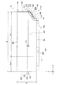
図1は、印刷材供給システム10の構成を示す斜視図である。図1には、互いに直交するXYZ軸が描かれている。図1のXYZ軸は他の図のXYZ軸に対応している。本実施形態では、Z軸方向が鉛直方向である。印刷材供給システム10は、カートリッジ20と、プリンター(印刷装置)50とを備える。印刷材供給システム10では、プリンター50のホルダー(カートリッジ装着部)600に、ユーザーによってカートリッジ20が着脱可能に装着される。
[Overall configuration of printing material supply system]
FIG. 1 is a perspective view showing the configuration of the printing material supply system 10. In FIG. 1, XYZ axes orthogonal to each other are drawn. The XYZ axes in FIG. 1 correspond to the XYZ axes in the other drawings. In the present embodiment, the Z-axis direction is the vertical direction. The printing material supply system 10 includes a cartridge 20 and a printer (printing apparatus) 50. In the printing material supply system 10, the cartridge 20 is detachably mounted on the holder (cartridge mounting unit) 600 of the printer 50 by the user.

印刷材供給システム10のカートリッジ20は、インク(印刷材)を収容する機能を有するカートリッジ(インクカートリッジ)であり、プリンター50に対して着脱可能に構成されている。カートリッジ20に収容された印刷材としてのインクは、後述する印刷材供給口および印刷材供給管を介してプリンター50のヘッド540に供給される。本実施形態では、プリンター50のホルダー600には、複数のカートリッジ20が着脱可能に装着される。本実施形態では、6色(ブラック、イエロー、マゼンタ、ライトマゼンタ、シアンおよびライトシアン)のインクに対応して6種類のカートリッジ20が1つずつ、すなわち合計6つのカートリッジ20がホルダー600に装着される。   The cartridge 20 of the printing material supply system 10 is a cartridge (ink cartridge) having a function of containing ink (printing material), and is configured to be detachable from the printer 50. The ink as the printing material accommodated in the cartridge 20 is supplied to the head 540 of the printer 50 through a printing material supply port and a printing material supply pipe which will be described later. In the present embodiment, a plurality of cartridges 20 are detachably mounted on the holder 600 of the printer 50. In the present embodiment, six types of cartridges 20 are attached to the holder 600 in correspondence with six colors (black, yellow, magenta, light magenta, cyan, and light cyan) of ink, that is, a total of six cartridges 20. .

ホルダー600に装着されるカートリッジの数は、6つに限るものではなく、プリンター50の構成に合わせて、任意の個数に変更可能であり、6つ以下であっても良いし、6つ以上であっても良い。カートリッジ20のインクの種類は、6色に限るものではなく、6色以下(例えば、ブラック、イエロー、マゼンタおよびシアンの4色)であっても、6色以上(例えば、本実施形態のインク色に特殊光沢色(金属光沢、パールホワイト等)を加えた色構成)であっても良い。他の実施形態では、1色のインクに対応して2つ以上のカートリッジ20がホルダー600に装着されても良い。カートリッジ20およびホルダー600の詳細構成については後述する。   The number of cartridges mounted in the holder 600 is not limited to six, and can be changed to an arbitrary number according to the configuration of the printer 50, and may be six or less, or six or more. There may be. The type of ink in the cartridge 20 is not limited to six colors, and six or more colors (for example, the ink colors of the present embodiment) even if there are six colors or less (for example, four colors of black, yellow, magenta, and cyan). And a special glossy color (metallic luster, pearl white, etc.). In another embodiment, two or more cartridges 20 may be mounted on the holder 600 corresponding to one color ink. Detailed configurations of the cartridge 20 and the holder 600 will be described later.

印刷材供給システム10のプリンター50は、インク(印刷材)を供給する機能を有する印刷装置を含むインクジェットプリンターである。プリンター50は、ホルダー600の他、制御部510と、キャリッジ520と、ヘッド540とを備える。プリンター50は、ホルダー600に装着されたカートリッジ20からヘッド540にインクを供給する機能(印刷装置)を有し、紙やラベルなどの印刷媒体90に対してヘッド540からインクを吐出することによって、文字、図形および画像などのデータを印刷媒体90に印刷する。   The printer 50 of the printing material supply system 10 is an ink jet printer including a printing apparatus having a function of supplying ink (printing material). In addition to the holder 600, the printer 50 includes a control unit 510, a carriage 520, and a head 540. The printer 50 has a function (printing apparatus) for supplying ink from the cartridge 20 mounted on the holder 600 to the head 540, and by ejecting ink from the head 540 to a print medium 90 such as paper or a label, Data such as characters, graphics, and images are printed on the print medium 90.

プリンター50の制御部510は、プリンター50の各部を制御する。プリンター50のキャリッジ520は、ヘッド540を印刷媒体90に対して相対的に移動可能に構成されている。プリンター50のヘッド540は、ホルダー600に装着されたカートリッジ20からインクの供給を受け、そのインクを印刷媒体90に吐出するインク吐出機構を備える。制御部510とキャリッジ520との間はフレキシブルケーブル517を介して電気的に接続されており、ヘッド540のインク吐出機構は、制御部510からの制御信号に基づいて動作する。   The control unit 510 of the printer 50 controls each unit of the printer 50. The carriage 520 of the printer 50 is configured to be able to move the head 540 relative to the print medium 90. The head 540 of the printer 50 includes an ink discharge mechanism that receives supply of ink from the cartridge 20 mounted in the holder 600 and discharges the ink onto the print medium 90. The controller 510 and the carriage 520 are electrically connected via a flexible cable 517, and the ink ejection mechanism of the head 540 operates based on a control signal from the controller 510.

本実施形態では、キャリッジ520には、ヘッド540と共にホルダー600が構成されている。このように、ヘッド540を移動させるキャリッジ520上のホルダー600にカートリッジ20が装着されるプリンターのタイプは、「オンキャリッジタイプ」とも呼ばれる。   In the present embodiment, the carriage 520 includes a holder 600 together with the head 540. In this way, the type of printer in which the cartridge 20 is mounted on the holder 600 on the carriage 520 that moves the head 540 is also referred to as an “on-carriage type”.

他の実施形態では、キャリッジ520とは異なる部位にホルダー600を構成し、ホルダー600に装着されたカートリッジ20からのインクを、フレキシブルチューブを介してキャリッジ520のヘッド540に供給しても良い。このようなプリンターのタイプは、「オフキャリッジタイプ」とも呼ばれる。   In another embodiment, the holder 600 may be configured at a site different from the carriage 520, and the ink from the cartridge 20 mounted on the holder 600 may be supplied to the head 540 of the carriage 520 via a flexible tube. Such a printer type is also called an “off-carriage type”.

本実施形態では、プリンター50は、キャリッジ520と印刷媒体90とを相対的に移動させて印刷媒体90に対する印刷を実現するために主走査送り機構および副走査送り機構を備える。プリンター50の主走査送り機構は、キャリッジモーター522および駆動ベルト524を備え、駆動ベルト524を介してキャリッジモーター522の動力をキャリッジ520に伝達することによって、キャリッジ520を主走査方向に往復移動させる。プリンター50の副走査送り機構は、搬送モーター532およびプラテン534を備え、搬送モーター532の動力をプラテン534に伝達することによって、主走査方向に直交する副走査方向に印刷媒体90を搬送する。主走査送り機構のキャリッジモーター522、および副走査送り機構の搬送モーター532は、制御部510からの制御信号に基づいて動作する。   In the present embodiment, the printer 50 includes a main scan feed mechanism and a sub scan feed mechanism in order to move the carriage 520 and the print medium 90 relative to each other to realize printing on the print medium 90. The main scanning feed mechanism of the printer 50 includes a carriage motor 522 and a driving belt 524, and transmits the power of the carriage motor 522 to the carriage 520 via the driving belt 524, thereby reciprocating the carriage 520 in the main scanning direction. The sub-scan feed mechanism of the printer 50 includes a transport motor 532 and a platen 534, and transmits the power of the transport motor 532 to the platen 534, thereby transporting the print medium 90 in the sub-scan direction orthogonal to the main scan direction. The carriage motor 522 of the main scan feed mechanism and the transport motor 532 of the sub scan feed mechanism operate based on a control signal from the control unit 510.

本実施形態では、印刷材供給システム10の使用状態において、印刷媒体90を搬送する副走査方向に沿った軸をX軸とし、キャリッジ520を往復移動させる主走査方向に沿った軸をY軸とし、重力方向に沿った軸をZ軸とする。これらX軸、Y軸およびZ軸は相互に直交する。なお、印刷材供給システム10の使用状態とは、水平な面に設置された印刷材供給システム10の状態であり、本実施形態では、水平な面はX軸およびY軸に平行な面である。   In this embodiment, when the printing material supply system 10 is in use, the axis along the sub-scanning direction for transporting the printing medium 90 is the X axis, and the axis along the main scanning direction for reciprocating the carriage 520 is the Y axis. The axis along the direction of gravity is the Z axis. These X axis, Y axis and Z axis are orthogonal to each other. The usage state of the printing material supply system 10 is the state of the printing material supply system 10 installed on a horizontal surface. In this embodiment, the horizontal surface is a surface parallel to the X axis and the Y axis. .

本実施形態では、副走査方向に向かって+X軸方向、その逆を−X軸方向とし、重力方向の下方から上方に向かって+Z軸方向、その逆を−Z軸方向とする。本実施形態では、+X軸方向側が印刷材供給システム10の正面となる。本実施形態では、印刷材供給システム10の右側面から左側面に向かって+Y軸方向、その逆を−Y軸方向とする。本実施形態では、ホルダー600に装着された複数のカートリッジ20の配列方向はY軸に沿った方向である。   In the present embodiment, the + X-axis direction toward the sub-scanning direction and the opposite thereof are defined as the −X-axis direction, the + Z-axis direction upward from the lower side of the gravity direction, and the opposite thereof as the −Z-axis direction. In the present embodiment, the + X axis direction side is the front surface of the printing material supply system 10. In the present embodiment, the + Y-axis direction from the right side surface of the printing material supply system 10 toward the left side surface, and the opposite is the −Y-axis direction. In the present embodiment, the arrangement direction of the plurality of cartridges 20 attached to the holder 600 is a direction along the Y axis.

〔カートリッジをホルダーに装着した構成〕
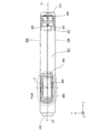
図2および図3は、カートリッジ20が装着されたホルダー600を示す斜視図である。図4は、カートリッジ20が装着されたホルダー600を示す上面図である。図5は、カートリッジ20が装着されたホルダー600を図4の矢視F5−F5で切断して示す断面図である。図2〜図5には、1つのカートリッジ20がホルダー600における設計された装着位置に正しく装着された状態を図示した。
[Configuration with cartridge mounted in holder]
2 and 3 are perspective views showing the holder 600 to which the cartridge 20 is mounted. FIG. 4 is a top view showing the holder 600 to which the cartridge 20 is mounted. FIG. 5 is a cross-sectional view showing the holder 600 to which the cartridge 20 is mounted cut along the arrow F5-F5 in FIG. 2 to 5 show a state where one cartridge 20 is correctly mounted at the designed mounting position in the holder 600.

プリンター50のホルダー600には、複数のカートリッジ20を装着可能に各カートリッジ20に対応して、カートリッジ20を受け入れ可能な複数のスロット(装着空間)が形成されている。プリンター50は、ホルダー600の各スロットに、インク供給管(印刷材供給管)640と、端子台700と、レバー800と、第1装置側係止部810と、第2装置側係止部620とを備える。   In the holder 600 of the printer 50, a plurality of slots (mounting spaces) capable of receiving the cartridges 20 are formed corresponding to the cartridges 20 so that the plurality of cartridges 20 can be mounted. The printer 50 includes an ink supply pipe (printing material supply pipe) 640, a terminal block 700, a lever 800, a first device side locking portion 810, and a second device side locking portion 620 in each slot of the holder 600. With.

図5に示すように、カートリッジ20は、プリンター50のホルダー600に形成されているスロットに合わせて、第1カートリッジ側係止部210と、第2カートリッジ側係止部220と、インク収容部(印刷材収容部)290と、インク供給口(印刷材供給口)280と、回路基板400とを備える。本実施形態では、カートリッジ20のインク供給口280には、インク収容部290に連通するインク流路282が形成されており、インク流路282を通じてインク収容部290からカートリッジ20の外部へとインクを供給することが可能である。本実施形態では、インク流路282の出口側には、インク流路282からの不用意なインクの漏出を防止する発泡樹脂体284が設けられている。   As shown in FIG. 5, the cartridge 20 has a first cartridge side locking portion 210, a second cartridge side locking portion 220, and an ink storage portion (in accordance with a slot formed in the holder 600 of the printer 50. A printing material container) 290, an ink supply port (printing material supply port) 280, and a circuit board 400. In the present embodiment, the ink supply port 280 of the cartridge 20 is formed with an ink flow path 282 that communicates with the ink storage portion 290, and ink is supplied from the ink storage portion 290 to the outside of the cartridge 20 through the ink flow path 282. It is possible to supply. In the present embodiment, a foamed resin body 284 that prevents inadvertent leakage of ink from the ink flow path 282 is provided on the outlet side of the ink flow path 282.

プリンター50のインク供給管640は、カートリッジ20のインク供給口280に接続することによって、カートリッジ20のインク収容部290からのインクをヘッド540へと供給可能に構成されている。インク供給管640は、カートリッジ側に接続される先端部642を有する。インク供給管640の基端部645は、ホルダー600の底面に設けられている。本実施形態では、図5に示すように、インク供給管640の中心軸CはZ軸と平行であり、中心軸Cに沿ってインク供給管640の基端部645から先端部642に向かう方向は+Z軸方向となる。   The ink supply tube 640 of the printer 50 is configured to be able to supply ink from the ink storage portion 290 of the cartridge 20 to the head 540 by connecting to the ink supply port 280 of the cartridge 20. The ink supply tube 640 has a tip portion 642 connected to the cartridge side. A base end portion 645 of the ink supply pipe 640 is provided on the bottom surface of the holder 600. In the present embodiment, as shown in FIG. 5, the central axis C of the ink supply tube 640 is parallel to the Z axis, and the direction from the proximal end 645 to the distal end 642 of the ink supply tube 640 is along the central axis C. Is the + Z-axis direction.

本実施形態では、インク供給管640の先端部642には、カートリッジ20からのインクを濾過する多孔体フィルター644が設けられている。多孔体フィルター644としては、例えば、ステンレスメッシュ、ステンレス不織布などを用いることができる。他の実施形態では、インク供給管640の先端部642から多孔体フィルターを省略しても良い。   In the present embodiment, a porous filter 644 that filters ink from the cartridge 20 is provided at the distal end 642 of the ink supply tube 640. As the porous filter 644, for example, a stainless mesh, a stainless nonwoven fabric, or the like can be used. In other embodiments, the porous filter may be omitted from the tip 642 of the ink supply tube 640.

本実施形態では、図2〜図5に示すように、インク供給管640の周囲には、カートリッジ20のインク供給口280を密閉することによってインク供給口280から周囲へのインクの漏出を防止する弾性部材648が設けられている。ホルダー600に装着された状態のカートリッジ20には、弾性部材648からインク供給口280に対して、+Z軸方向の成分を含む付勢力Psが付与される。   In this embodiment, as shown in FIGS. 2 to 5, the ink supply port 280 of the cartridge 20 is sealed around the ink supply tube 640 to prevent ink leakage from the ink supply port 280 to the surroundings. An elastic member 648 is provided. A biasing force Ps including a component in the + Z-axis direction is applied from the elastic member 648 to the ink supply port 280 to the cartridge 20 mounted in the holder 600.

プリンター50の端子台700は、インク供給管640よりも+X軸方向側に設けられている。端子台700には、カートリッジ20の回路基板400に設けられたカートリッジ側端子と電気的に接続可能な装置側端子が設けられている。ホルダー600に装着された状態のカートリッジ20には、端子台700に設けられた装置側端子から回路基板400に対して、+Z軸方向の成分を含む付勢力Ptが付与される。   The terminal block 700 of the printer 50 is provided on the + X axis direction side of the ink supply pipe 640. The terminal block 700 is provided with device-side terminals that can be electrically connected to the cartridge-side terminals provided on the circuit board 400 of the cartridge 20. A biasing force Pt including a component in the + Z-axis direction is applied to the circuit board 400 from the device-side terminal provided on the terminal block 700 to the cartridge 20 in a state of being mounted in the holder 600.

プリンター50における第1装置側係止部810は、レバー800の一部として設けられ、第1係止位置810Lで第1カートリッジ側係止部210を係止する。第1係止位置810Lは、回路基板400と端子台700に設けられた装置側端子とが接触する位置よりも+Z軸方向側かつ+X軸方向側に位置する。第1装置側係止部810は、第1カートリッジ側係止部210を係止することによって、カートリッジ20の+Z軸方向への移動を制限する。   The first device side locking portion 810 in the printer 50 is provided as a part of the lever 800, and locks the first cartridge side locking portion 210 at the first locking position 810L. The first locking position 810L is located on the + Z-axis direction side and the + X-axis direction side from the position where the circuit board 400 and the device-side terminal provided on the terminal block 700 are in contact. The first device side locking portion 810 limits the movement of the cartridge 20 in the + Z-axis direction by locking the first cartridge side locking portion 210.

プリンター50における第2装置側係止部620は、ホルダー600の一部として設けられ、第2係止位置620Lで第2カートリッジ側係止部220を係止可能に構成されている。本実施形態では、第2カートリッジ側係止部220は、ホルダー600に固設されている。第2係止位置620Lは、インク供給管640よりも+Z軸方向側かつ−X軸方向側に位置する。第2装置側係止部620は、第2カートリッジ側係止部220を係止することによって、カートリッジ20の+Z軸方向への移動を制限する。   The second device side locking portion 620 in the printer 50 is provided as a part of the holder 600, and is configured to be able to lock the second cartridge side locking portion 220 at the second locking position 620L. In the present embodiment, the second cartridge side locking portion 220 is fixed to the holder 600. The second locking position 620L is located on the + Z axis direction side and the −X axis direction side of the ink supply pipe 640. The second device side locking portion 620 limits the movement of the cartridge 20 in the + Z-axis direction by locking the second cartridge side locking portion 220.

ホルダー600対するカートリッジ20の着脱時には、相互に係合させた第2カートリッジ側係止部220と第2装置側係止部620とを回転支点として、Z軸およびX軸に平行な平面に沿ってカートリッジ20を回転させながら、カートリッジ20の着脱が行われる。すなわち、第2カートリッジ側係止部220および第2装置側係止部620は、カートリッジ20の着脱時にカートリッジ20の回転支点として機能する。ホルダー600に対するカートリッジ20の着脱動作の詳細については後述する。   When the cartridge 20 is attached to and detached from the holder 600, the second cartridge side locking portion 220 and the second device side locking portion 620 engaged with each other are used as rotation fulcrums along a plane parallel to the Z axis and the X axis. The cartridge 20 is attached and detached while rotating the cartridge 20. That is, the second cartridge side locking portion 220 and the second device side locking portion 620 function as a rotation fulcrum of the cartridge 20 when the cartridge 20 is attached and detached. Details of the attaching / detaching operation of the cartridge 20 with respect to the holder 600 will be described later.

プリンター50のレバー800は、第1装置側係止部810が第1カートリッジ側係止部210を係止する第1係止位置810Lよりも+Z軸方向側かつ+X軸方向側に回動中心800cを有する。レバー800は、第1装置側係止部810が第1係止位置810Lから+X軸方向に移動するように回動することによって、第1装置側係止部810による第1カートリッジ側係止部210の係止および係止解除を可能に構成されている。   The lever 800 of the printer 50 has a rotation center 800c on the + Z axis direction side and the + X axis direction side from the first locking position 810L where the first device side locking portion 810 locks the first cartridge side locking portion 210. Have The lever 800 rotates so that the first device side locking portion 810 moves in the + X-axis direction from the first locking position 810L, whereby the first cartridge side locking portion by the first device side locking portion 810 is obtained. 210 is configured to be able to be locked and unlocked.

レバー800には、ユーザーによる−X軸方向側に向かう操作力Prを受け付け可能に構成された操作部830が、回動中心800cよりも+Z軸方向側かつ+X軸方向側に形成されている。ユーザーによる操作力Prが操作部830に付与されると、第1装置側係止部810が第1係止位置810Lから+X軸方向に移動するようにレバー800が回動することによって、第1装置側係止部810による第1カートリッジ側係止部210の係止が解除される。これによって、ホルダー600からカートリッジ20を取り外すことが可能になる。   The lever 800 is formed with an operation portion 830 configured to receive an operation force Pr directed toward the −X axis direction by the user on the + Z axis direction side and the + X axis direction side from the rotation center 800c. When the operation force Pr by the user is applied to the operation unit 830, the lever 800 is rotated so that the first device side locking unit 810 moves from the first locking position 810L in the + X-axis direction. The locking of the first cartridge side locking portion 210 by the apparatus side locking portion 810 is released. As a result, the cartridge 20 can be removed from the holder 600.

図5に示すように、カートリッジ20がホルダー600に装着された状態では、第1係止位置810Lが第2係止位置620Lよりも距離Dzを置いて−Z軸方向側に位置する。そのため、ホルダー600からカートリッジ20に対する付勢力Ps,Ptは、第2係止位置620Lをカートリッジ20の回転支点とするモーメントの釣り合いの関係上、第1カートリッジ側係止部210と第1装置側係止部810との係止を強くする方向(+X軸成分および+Z軸成分を含む方向)に作用する。これによって、設計された装着位置にカートリッジ20を安定して保持することができる。   As shown in FIG. 5, in a state where the cartridge 20 is mounted in the holder 600, the first locking position 810L is positioned on the −Z axis direction side with a distance Dz from the second locking position 620L. Therefore, the urging forces Ps and Pt from the holder 600 to the cartridge 20 are related to the first cartridge side locking portion 210 and the first device side due to the moment balance with the second locking position 620L as the rotation fulcrum of the cartridge 20. It acts in a direction (a direction including a + X-axis component and a + Z-axis component) that strengthens the locking with the stop portion 810. Thus, the cartridge 20 can be stably held at the designed mounting position.

〔カートリッジの詳細構成〕
図6は、カートリッジ20の構成を示す斜視図である。図7は、カートリッジ20の構成を示す正面図である。図8は、カートリッジ20の構成を示す背面図である。図9は、カートリッジ20の構成を示す左側面図である。図10は、カートリッジ20の構成を示す底面図である。
[Detailed configuration of cartridge]
FIG. 6 is a perspective view showing the configuration of the cartridge 20. FIG. 7 is a front view showing the configuration of the cartridge 20. FIG. 8 is a rear view showing the configuration of the cartridge 20. FIG. 9 is a left side view showing the configuration of the cartridge 20. FIG. 10 is a bottom view showing the configuration of the cartridge 20.

カートリッジ20の説明では、ホルダー600に装着された装着状態にあるカートリッジ20に対するX軸、Y軸およびZ軸をカートリッジ上の軸とする。本実施形態では、カートリッジ20がホルダー600に装着された装着状態で、+X軸方向側がカートリッジ20の正面となる。図7、図8および図10に図示した平面CXは、中心軸Cを通り、かつ、Z軸およびX軸に平行な平面である。図7、図8および図10に図示した平面Ycは、カートリッジ20のY軸に沿った方向の長さ(幅)の中央を通り、かつ、Z軸およびX軸に平行な平面である。   In the description of the cartridge 20, the X axis, the Y axis, and the Z axis with respect to the cartridge 20 that is mounted in the holder 600 are axes on the cartridge. In the present embodiment, the + X-axis direction side is the front surface of the cartridge 20 when the cartridge 20 is mounted in the holder 600. The plane CX illustrated in FIGS. 7, 8, and 10 is a plane that passes through the central axis C and is parallel to the Z axis and the X axis. The plane Yc shown in FIGS. 7, 8, and 10 is a plane that passes through the center of the length (width) in the direction along the Y axis of the cartridge 20 and is parallel to the Z axis and the X axis.

図6〜図10に示すように、カートリッジ20は、直方体を基調とした外形を構成する6つの平面として、第1面201と、第2面202と、第3面203と、第4面204と、第5面205と、第6面206とを有する。本実施形態では、カートリッジ20は、直方体の6つの平面に対応する第1面201〜第6面206の他、第1面201と第3面203との間に、更に、第7面207と、第8面208とを有する。これら第1面201〜第8面208の内側にはインク収容部290が形成されている。   As shown in FIGS. 6 to 10, the cartridge 20 has a first surface 201, a second surface 202, a third surface 203, and a fourth surface 204 as six planes constituting an outer shape based on a rectangular parallelepiped. And a fifth surface 205 and a sixth surface 206. In the present embodiment, the cartridge 20 includes a first surface 201 to a sixth surface 206 corresponding to six planes of a rectangular parallelepiped, a first surface 201 and a third surface 203, and a seventh surface 207. , And an eighth surface 208. An ink storage portion 290 is formed inside the first surface 201 to the eighth surface 208.

第1面201〜第8面208は、概形として平面を形成しており、面の全域が完全に平坦である必要はなく、面の一部に凹凸を有していても良い。本実施形態では、第1面201〜第8面208は、複数の部材を組み立てた組立体の外表面である。本実施形態では、第1面201〜第8面208は、板状の部材で形成されている。他の実施形態では、第1面201〜第8面208の一部は、フィルム状(薄膜状)の部材で形成されていても良い。第1面201〜第8面208は、樹脂製であり、本実施形態では、ポリプロピレン(PP)よりも高い剛性を得ることが可能な材料(例えば、ポリアセタール(POM))で形成されている。   The first surface 201 to the eighth surface 208 form a flat surface as a rough shape, and it is not necessary that the entire surface is completely flat, and a part of the surface may have irregularities. In the present embodiment, the first surface 201 to the eighth surface 208 are outer surfaces of an assembly in which a plurality of members are assembled. In the present embodiment, the first surface 201 to the eighth surface 208 are formed of plate-like members. In another embodiment, a part of the first surface 201 to the eighth surface 208 may be formed of a film-like (thin film-like) member. The first surface 201 to the eighth surface 208 are made of resin, and in this embodiment, are formed of a material (for example, polyacetal (POM)) that can obtain higher rigidity than polypropylene (PP).

本実施形態では、カートリッジ20の奥行きD(X軸方向の長さ)、幅W(Y軸方向の長さ)、高さH(Z軸方向の長さ)は、奥行きD、高さH、幅Wの順に大きい。
すなわち、奥行きDは高さHよりも大きく、高さHは幅Wよりも大きい。また、奥行きDは高さH及び幅Wよりも大きく、高さHは幅Wよりも大きい。
In this embodiment, the depth D (length in the X-axis direction), the width W (length in the Y-axis direction), and the height H (length in the Z-axis direction) of the cartridge 20 are the depth D, the height H, The width W increases in order.
That is, the depth D is greater than the height H, and the height H is greater than the width W. The depth D is greater than the height H and the width W, and the height H is greater than the width W.

カートリッジ20の第1面201および第2面202は、X軸およびY軸に平行な面であり、Z軸方向において相互に対向する位置関係にある。第1面201が−Z軸方向側、第2面202が+Z軸方向側に位置する。第1面201および第2面202は、第3面203、第4面204、第5面205および第6面206と交わる位置関係にある。
なお、本明細書では、2つの面が「交わる」とは、2つの面が相互に繋がって交わる状態と、一方の面の延長面が他方の面に交わる状態と、相互の延長面が交わる状態と、のいずれかの状態であることを意図する。
本実施形態では、カートリッジ20がホルダー600に装着された装着状態で、第1面201はカートリッジ20の底面を構成し、第2面202はカートリッジ20の上面を構成する。
すなわち、第1面201は底面、第2面202は上面、第3面203は正面、第4面204は背面、第5面205は左側面、第6面206は右側面とも呼ぶ。
The first surface 201 and the second surface 202 of the cartridge 20 are surfaces parallel to the X axis and the Y axis, and are in a positional relationship facing each other in the Z axis direction. The first surface 201 is located on the −Z axis direction side, and the second surface 202 is located on the + Z axis direction side. The first surface 201 and the second surface 202 are in a positional relationship with the third surface 203, the fourth surface 204, the fifth surface 205, and the sixth surface 206.
In this specification, two surfaces "intersect" means that two surfaces are connected to each other, a state where one surface is extended to the other surface, and a surface where the other surfaces are extended to each other. It is intended to be one of the states.
In the present embodiment, the first surface 201 constitutes the bottom surface of the cartridge 20 and the second surface 202 constitutes the top surface of the cartridge 20 in the mounted state where the cartridge 20 is mounted in the holder 600.
That is, the first surface 201 is also referred to as the bottom surface, the second surface 202 is referred to as the top surface, the third surface 203 is referred to as the front surface, the fourth surface 204 is referred to as the back surface, the fifth surface 205 is referred to as the left side surface, and the sixth surface 206 is referred to as the right side surface.

第1面201には、インク供給口280が形成されている。インク供給口280は、第1面201から−Z軸方向に突出しており、X軸およびY軸に平行な面に開口を有する開口面288を−Z軸方向の端部に形成する。本実施形態では、図10に示すように、インク供給口280の内側には、開口面288から+Z軸方向側の内側に発泡樹脂体284が設けられている。本実施形態では、カートリッジ20の工場出荷時に、インク供給口280の開口面288は、キャップまたはフィルムなどの封止部材(図示しない)で封止され、その後、ホルダー600に対するカートリッジ20の装着時に、開口面288を封止する封止部材(図示しない)は、カートリッジ20から取り外される。   An ink supply port 280 is formed on the first surface 201. The ink supply port 280 protrudes from the first surface 201 in the −Z-axis direction, and forms an opening surface 288 having an opening in a plane parallel to the X-axis and the Y-axis at the end in the −Z-axis direction. In the present embodiment, as shown in FIG. 10, a foamed resin body 284 is provided inside the ink supply port 280 on the inner side of the opening surface 288 on the + Z axis direction side. In the present embodiment, when the cartridge 20 is shipped from the factory, the opening surface 288 of the ink supply port 280 is sealed with a sealing member (not shown) such as a cap or a film, and then when the cartridge 20 is mounted on the holder 600, A sealing member (not shown) that seals the opening surface 288 is removed from the cartridge 20.

本実施形態では、インク供給口280は、インク供給管640の中心軸Cを中心として−Z軸方向に突出しているが、他の実施形態では、インク供給口280の中心がインク供給管640の中心軸Cから外れていても良い。本実施形態では、−Z軸方向から+Z軸方向に向って見たインク供給口280の開口面288は、X軸およびY軸にそれぞれ平行な軸に対して線対称の外郭を有するが、他の実施形態では、非対称の外郭であっても良い。
本実施形態では、Z軸方向から見た開口面288の形状は、長方形の角を丸めた形状であるが、他の実施形態において、正円、楕円、長円、正方形、長方形などの形状であっても良い。
In the present embodiment, the ink supply port 280 protrudes in the −Z-axis direction around the central axis C of the ink supply tube 640, but in other embodiments, the center of the ink supply port 280 is the center of the ink supply tube 640. It may deviate from the central axis C. In this embodiment, the opening surface 288 of the ink supply port 280 viewed from the −Z-axis direction toward the + Z-axis direction has a line-symmetric outline with respect to axes parallel to the X-axis and the Y-axis, respectively. In this embodiment, an asymmetric outline may be used.
In the present embodiment, the shape of the opening surface 288 viewed from the Z-axis direction is a shape obtained by rounding the corners of a rectangle. However, in other embodiments, the shape of the opening surface 288 is a shape such as a perfect circle, an ellipse, an ellipse, a square, or a rectangle. There may be.

カートリッジ20の第3面203および第4面204は、Y軸およびZ軸に平行な面であり、X軸方向おいて相互に対向する位置関係にある。第3面203が+X軸方向側、第4面204が−X軸方向側に位置する。第3面203および第4面204は、第1面201、第2面202、第5面205および第6面206と交わる位置関係にある。本実施形態では、カートリッジ20がホルダー600に装着された装着状態で、第3面203はカートリッジ20の正面を構成し、第4面204はカートリッジ20の背面を構成する。   The third surface 203 and the fourth surface 204 of the cartridge 20 are surfaces parallel to the Y-axis and the Z-axis, and are in a positional relationship facing each other in the X-axis direction. The third surface 203 is located on the + X axis direction side, and the fourth surface 204 is located on the −X axis direction side. The third surface 203 and the fourth surface 204 are in a positional relationship with the first surface 201, the second surface 202, the fifth surface 205, and the sixth surface 206. In the present embodiment, the third surface 203 constitutes the front surface of the cartridge 20 and the fourth surface 204 constitutes the back surface of the cartridge 20 with the cartridge 20 mounted in the holder 600.

第3面203には、第1カートリッジ側係止部210が形成されている。第1カートリッジ側係止部210は、インク供給口280および回路基板400よりも+Z軸方向側かつ+X軸方向側に設けられている。第1カートリッジ側係止部210は、+Z軸方向を向いた第1係止面211を有し、レバー800の回動により第1係止位置810Lに位置決めされた第1装置側係止部810が第1係止面211に係止することによって、カートリッジ20の+Z軸方向への移動を制限可能に構成されている。   A first cartridge side locking portion 210 is formed on the third surface 203. The first cartridge side locking portion 210 is provided on the + Z axis direction side and the + X axis direction side from the ink supply port 280 and the circuit board 400. The first cartridge side locking portion 210 has a first locking surface 211 facing the + Z-axis direction, and is positioned at the first locking position 810L by the rotation of the lever 800. Is configured to be able to limit the movement of the cartridge 20 in the + Z-axis direction by being locked to the first locking surface 211.

本実施形態では、第1カートリッジ側係止部210は、第3面203から+X軸方向に突出した凸部である。これによって、第1カートリッジ側係止部210を第3面203に容易に形成することができる。また、カートリッジ20の装着時にユーザーが第1カートリッジ側係止部210を容易に確認することができる。   In the present embodiment, the first cartridge side locking portion 210 is a convex portion that protrudes from the third surface 203 in the + X-axis direction. Accordingly, the first cartridge side locking portion 210 can be easily formed on the third surface 203. Further, the user can easily check the first cartridge side locking portion 210 when the cartridge 20 is mounted.

本実施形態では、図6、図7および図9に示すように、第1カートリッジ側係止部210は、二つの辺がそれぞれY軸およびZ軸に平行なL字状に第3面203から突出した凸部であり、そのL字状凸部におけるY軸に平行な部位のY軸方向の中央から−Z軸方向側には、Y軸に沿った方向から見て三角形の壁部が、L字状凸部の+X軸方向側の端部から第3面203に向けて形成されている。   In this embodiment, as shown in FIGS. 6, 7, and 9, the first cartridge side locking portion 210 has an L shape in which two sides are parallel to the Y axis and the Z axis, respectively, from the third surface 203. From the center in the Y-axis direction of the portion parallel to the Y-axis in the L-shaped convex portion to the −Z-axis direction side, a triangular wall portion when viewed from the direction along the Y-axis, It is formed from the end of the L-shaped convex part on the + X-axis direction side toward the third surface 203.

本実施形態では、第1カートリッジ側係止部210は、+Z軸方向を向いた第1係止面211に加え、+X軸方向を向いた第3係止面213を有し、レバー800の回動により第1係止位置810Lに位置決めされた第1装置側係止部810が第1係止面211および第3係止面213に係止することによって、カートリッジ20の+Z軸方向および+X軸方向への移動を制限可能に構成されている。これによって、設計された装着位置にカートリッジ20をより安定した状態で保持することができる。   In the present embodiment, the first cartridge side locking portion 210 has a third locking surface 213 facing the + X-axis direction in addition to the first locking surface 211 facing the + Z-axis direction. The first device side locking portion 810 positioned at the first locking position 810L by movement is locked to the first locking surface 211 and the third locking surface 213, so that the + Z axis direction and the + X axis of the cartridge 20 are The movement in the direction can be restricted. Thus, the cartridge 20 can be held in a more stable state at the designed mounting position.

本実施形態では、第1カートリッジ側係止部210の第1係止面211は、L字状凸部におけるY軸に平行な部位を構成する+Z軸方向を向いた平面として形成されている。
すなわち、第1係止面211は、X軸およびY軸に平行な平面である。本実施形態では、第1カートリッジ側係止部210の第3係止面213は、L字状凸部におけるY軸に平行な部位を構成する+X軸方向を向いた平面として形成されている。すなわち、第3係止面213は、Y軸およびZ軸に平行な平面である。
In the present embodiment, the first locking surface 211 of the first cartridge side locking portion 210 is formed as a plane facing the + Z-axis direction that constitutes a portion parallel to the Y axis in the L-shaped convex portion.
That is, the first locking surface 211 is a plane parallel to the X axis and the Y axis. In the present embodiment, the third locking surface 213 of the first cartridge side locking portion 210 is formed as a plane facing the + X-axis direction that constitutes a portion parallel to the Y-axis in the L-shaped convex portion. That is, the third locking surface 213 is a plane parallel to the Y axis and the Z axis.

本実施形態では、第1カートリッジ側係止部210は、−Z軸方向および+X軸方向を向いて傾斜する傾斜面216を有する。傾斜面216の+Z軸方向側は、第1係止面211の+X軸方向側に隣接する第3係止面213の−Z軸方向側に隣接し、傾斜面216の−Z軸方向側は、第3面203と第8面208とが隣接する部位に隣接する。これによって、カートリッジ20をホルダー600に装着する際に、第1装置側係止部810を第1係止面211へと円滑に誘導することができる。本実施形態では、第1カートリッジ側係止部210の傾斜面216は、L字状凸部の−Z軸方向側に形成された三角状壁部を構成する+X軸方向側の平面として形成されている。   In the present embodiment, the first cartridge side locking portion 210 has an inclined surface 216 that is inclined toward the −Z axis direction and the + X axis direction. The + Z-axis direction side of the inclined surface 216 is adjacent to the −Z-axis direction side of the third locking surface 213 adjacent to the + X-axis direction side of the first locking surface 211, and the −Z-axis direction side of the inclined surface 216 is The third surface 203 and the eighth surface 208 are adjacent to the adjacent portion. Thus, when the cartridge 20 is mounted on the holder 600, the first device side locking portion 810 can be smoothly guided to the first locking surface 211. In the present embodiment, the inclined surface 216 of the first cartridge side locking portion 210 is formed as a flat surface on the + X axis direction side constituting a triangular wall portion formed on the −Z axis direction side of the L-shaped convex portion. ing.

本実施形態では、第1カートリッジ側係止部210は、第1係止面211の+X軸方向側に隣接する第3係止面213の一部を+Z軸方向に延長した延長面218を有する。
これによって、カートリッジ20をホルダー600に装着する際に、レバー800が第1係止面211の+Z軸方向側に乗り上がってしまうことを防止することができる。本実施形態では、第1カートリッジ側係止部210の延長面218は、L字状凸部におけるZ軸に平行な部位を構成する+X軸方向を向いた平面として形成されている。すなわち、延長面218は、Y軸およびZ軸に平行な平面である。
In the present embodiment, the first cartridge side locking portion 210 has an extended surface 218 that extends a part of the third locking surface 213 adjacent to the + X axis direction side of the first locking surface 211 in the + Z axis direction. .
Accordingly, when the cartridge 20 is mounted on the holder 600, the lever 800 can be prevented from riding on the + Z axis direction side of the first locking surface 211. In the present embodiment, the extended surface 218 of the first cartridge side locking portion 210 is formed as a plane facing the + X axis direction that constitutes a portion parallel to the Z axis in the L-shaped convex portion. That is, the extended surface 218 is a plane parallel to the Y axis and the Z axis.

本実施形態では、第3面203には、突出部260が形成されている。突出部260は、第2面202を+X軸方向に延長した形状を有し、第3面203から+X軸方向に突出している。カートリッジ20に突出部260が形成されているため、カートリッジ20をホルダー600から取り外す際には、ユーザーは、−X軸方向側に向けてレバー800の操作部830を押した指を、そのまま突出部260に引っ掛けることによって、第2カートリッジ側係止部220を回転支点とした+Z軸方向へのカートリッジ20の持ち上げを容易に行うことが可能である。他の実施形態では、第3面203から突出部260を省略しても良い。   In the present embodiment, a protrusion 260 is formed on the third surface 203. The protrusion 260 has a shape obtained by extending the second surface 202 in the + X-axis direction, and protrudes from the third surface 203 in the + X-axis direction. Since the cartridge 20 is formed with the protruding portion 260, when removing the cartridge 20 from the holder 600, the user presses the finger that pressed the operation portion 830 of the lever 800 toward the −X axis direction side as it is. By being hooked on 260, it is possible to easily lift the cartridge 20 in the + Z-axis direction with the second cartridge side locking portion 220 as the rotation fulcrum. In other embodiments, the protrusion 260 may be omitted from the third surface 203.

第4面204には、第2カートリッジ側係止部220が形成されている。第2カートリッジ側係止部220は、インク供給口280および回路基板400よりも+Z軸方向側かつ−X軸方向側に設けられている。第2カートリッジ側係止部220は、+Z軸方向を向いた第2係止面222を有し、第2装置側係止部620が第2係止面222に係止することによって、カートリッジ20の+Z軸方向への移動を制限可能に構成されている。   A second cartridge side locking portion 220 is formed on the fourth surface 204. The second cartridge side locking portion 220 is provided on the + Z axis direction side and the −X axis direction side from the ink supply port 280 and the circuit board 400. The second cartridge side locking portion 220 has a second locking surface 222 facing the + Z-axis direction, and the second device side locking portion 620 locks to the second locking surface 222, whereby the cartridge 20 The movement in the + Z axis direction can be restricted.

本実施形態では、第2カートリッジ側係止部220は、ホルダー600に対するカートリッジ20の着脱時に第2装置側係止部620と係合することによって、ホルダー600に対するカートリッジ20の回転支点としても機能するように構成されている。これによって、ホルダー600に対するカートリッジ20の脱着を容易に行うことができる。   In the present embodiment, the second cartridge side locking portion 220 also functions as a rotation fulcrum of the cartridge 20 with respect to the holder 600 by engaging with the second device side locking portion 620 when the cartridge 20 is attached to and detached from the holder 600. It is configured as follows. Thereby, the cartridge 20 can be easily attached to and detached from the holder 600.

本実施形態では、第2カートリッジ側係止部220は、第4面204から−X軸方向に突出した凸部である。これによって、第2カートリッジ側係止部220を第4面204に容易に形成することができる。また、カートリッジ20の装着時にユーザーが第2カートリッジ側係止部220を容易に確認することができる。   In the present embodiment, the second cartridge side locking portion 220 is a convex portion protruding from the fourth surface 204 in the −X axis direction. Thus, the second cartridge side locking portion 220 can be easily formed on the fourth surface 204. Further, the user can easily confirm the second cartridge side locking portion 220 when the cartridge 20 is mounted.

本実施形態では、第2カートリッジ側係止部220の第2係止面222は、第4面204から−X軸方向に突出した凸部を構成する+Z軸方向を向いた平面として形成されている。すなわち、第2係止面222は、X軸およびY軸に平行な平面である。   In the present embodiment, the second locking surface 222 of the second cartridge side locking portion 220 is formed as a plane facing the + Z axis direction that constitutes a convex portion protruding from the fourth surface 204 in the −X axis direction. Yes. That is, the second locking surface 222 is a plane parallel to the X axis and the Y axis.

本実施形態では、第2カートリッジ側係止部220は、第2係止面222の−X軸方向側に隣接する傾斜面224を有し、傾斜面224は、+Z軸方向および−X軸方向を向いて傾斜している。これによって、カートリッジ20をホルダー600に装着する際に、第2係止面222を第2装置側係止部620へと円滑に誘導することができる。他の実施形態では、傾斜面224を省略しても良い。   In the present embodiment, the second cartridge side locking portion 220 has an inclined surface 224 adjacent to the −X axis direction side of the second locking surface 222, and the inclined surface 224 includes the + Z axis direction and the −X axis direction. It is inclined to face. Thus, when the cartridge 20 is mounted on the holder 600, the second locking surface 222 can be smoothly guided to the second device side locking portion 620. In other embodiments, the inclined surface 224 may be omitted.

図9に示すように、第1カートリッジ側係止部210の第1係止面211は、第2カートリッジ側係止部220の第2係止面222よりも距離Dzを置いて、−Z軸方向側、すなわち、第1面201側に設けられている。言い換えると、第2係止面222は、第1係止面211よりも距離Dzを置いて、+Z軸方向側、すなわち、第2面202側に設けられている。これによって、カートリッジ20がホルダー600に装着された装着状態で、第1カートリッジ側係止部210と第1装置側係止部810との係止を強くすることができる。   As shown in FIG. 9, the first locking surface 211 of the first cartridge side locking portion 210 is positioned at a distance Dz from the second locking surface 222 of the second cartridge side locking portion 220, and the −Z axis It is provided on the direction side, that is, on the first surface 201 side. In other words, the second locking surface 222 is provided on the + Z-axis direction side, that is, on the second surface 202 side with a distance Dz from the first locking surface 211. Accordingly, the first cartridge side locking portion 210 and the first device side locking portion 810 can be strongly locked with the cartridge 20 mounted in the holder 600.

本実施形態では、図7、図8、図10に示すように、第1カートリッジ側係止部210の第1係止面211、および第2カートリッジ側係止部220の第2係止面222は、カートリッジ20の幅(Y軸方向の長さ)の中央を通る平面Ycを横切る位置に設けられている。これによって、ホルダー600からカートリッジ20に対する付勢力Ps,Ptがカートリッジ20をY軸方向に傾かせる力として働く作用を抑制することができる。   In the present embodiment, as shown in FIGS. 7, 8, and 10, the first locking surface 211 of the first cartridge side locking portion 210 and the second locking surface 222 of the second cartridge side locking portion 220. Is provided at a position crossing a plane Yc passing through the center of the width (length in the Y-axis direction) of the cartridge 20. Accordingly, it is possible to suppress the action of the urging forces Ps and Pt from the holder 600 acting on the cartridge 20 as a force that tilts the cartridge 20 in the Y-axis direction.

本実施形態では、図7、図8、図10に示すように、第1カートリッジ側係止部210の第1係止面211、および第2カートリッジ側係止部220の第2係止面222は、中心軸Cを通る平面CXを横切る位置に設けられている。これによって、ホルダー600からカートリッジ20に対する付勢力Psがカートリッジ20をY軸方向に傾かせる力として働く作用を効果的に抑制することができる。   In the present embodiment, as shown in FIGS. 7, 8, and 10, the first locking surface 211 of the first cartridge side locking portion 210 and the second locking surface 222 of the second cartridge side locking portion 220. Is provided at a position crossing the plane CX passing through the central axis C. Accordingly, it is possible to effectively suppress the action of the urging force Ps applied from the holder 600 to the cartridge 20 as a force for tilting the cartridge 20 in the Y-axis direction.

本実施形態では、図9に示すように、中心軸Cと第3面203とのX軸上の距離Dx1は、中心軸Cと第4面204とのX軸上の距離Dx2よりも長い。すなわち、インク供給口280に対するX軸上の距離は、第1カートリッジ側係止部210の第1係止面211よりも、第2カートリッジ側係止部220の第2係止面222の方が近い。これによって、第1係止面211よりも先にホルダー600に対して位置決めされる第2係止面222側にインク供給口280が形成されているため、ホルダー600に対するカートリッジ20の位置決めを容易に行うことができる。   In the present embodiment, as shown in FIG. 9, the distance Dx1 on the X axis between the central axis C and the third surface 203 is longer than the distance Dx2 on the X axis between the central axis C and the fourth surface 204. That is, the distance on the X-axis with respect to the ink supply port 280 is greater on the second locking surface 222 of the second cartridge side locking portion 220 than on the first locking surface 211 of the first cartridge side locking portion 210. close. Accordingly, since the ink supply port 280 is formed on the second locking surface 222 side that is positioned with respect to the holder 600 before the first locking surface 211, the cartridge 20 can be easily positioned with respect to the holder 600. It can be carried out.

本実施形態では、図10に示すように、第1カートリッジ側係止部210のY軸方向の長さは、第2カートリッジ側係止部220のY軸方向の長さよりも小さい。本実施形態では、第1カートリッジ側係止部210のY軸方向の長さは、回路基板400のY軸方向の長さよりも小さい。本実施形態では、第2カートリッジ側係止部220のY軸方向の長さは、回路基板400のY軸方向の長さにほぼ等しい。   In the present embodiment, as shown in FIG. 10, the length of the first cartridge side locking portion 210 in the Y axis direction is smaller than the length of the second cartridge side locking portion 220 in the Y axis direction. In the present embodiment, the length of the first cartridge side locking portion 210 in the Y axis direction is smaller than the length of the circuit board 400 in the Y axis direction. In the present embodiment, the length of the second cartridge side locking portion 220 in the Y axis direction is substantially equal to the length of the circuit board 400 in the Y axis direction.

カートリッジ20の第5面205および第6面206は、Z軸およびX軸に平行な面であり、Y軸方向において相互に対向する位置関係にある。第5面205が+Y軸方向側、第6面206が−Y軸方向側に位置する。第5面205および第6面206は、第1面201、第2面202、第3面203および第4面204と交わる位置関係にある。本実施形態では、カートリッジ20がホルダー600に装着された装着状態で、第5面205はカートリッジ20の左側面を構成し、第6面206はカートリッジ20の右側面を構成する。   The fifth surface 205 and the sixth surface 206 of the cartridge 20 are surfaces parallel to the Z-axis and the X-axis, and are in a positional relationship facing each other in the Y-axis direction. The fifth surface 205 is located on the + Y axis direction side, and the sixth surface 206 is located on the −Y axis direction side. The fifth surface 205 and the sixth surface 206 are in a positional relationship where they intersect with the first surface 201, the second surface 202, the third surface 203, and the fourth surface 204. In the present embodiment, the fifth surface 205 constitutes the left side surface of the cartridge 20 and the sixth surface 206 constitutes the right side surface of the cartridge 20 when the cartridge 20 is attached to the holder 600.

カートリッジ20の第7面207は、第1面201と第3面203とを繋ぐコーナー部に設けられ、第1面201から+Z軸方向側に延びるように形成された面である。第7面207は、+Z軸方向側で第8面208と繋がり、−Z軸方向側で第1面201と繋がる。本実施形態では、第7面207は、Y軸およびZ軸に平行な面であり、第4面204に対向する位置関係にある。   The seventh surface 207 of the cartridge 20 is a surface that is provided at a corner portion connecting the first surface 201 and the third surface 203 and extends from the first surface 201 to the + Z-axis direction side. The seventh surface 207 is connected to the eighth surface 208 on the + Z axis direction side and is connected to the first surface 201 on the −Z axis direction side. In the present embodiment, the seventh surface 207 is a surface parallel to the Y axis and the Z axis, and is in a positional relationship facing the fourth surface 204.

カートリッジ20の第8面208は、第1面201と第3面203とを繋ぐコーナー部に設けられ、第7面207よりも+Z軸方向側に形成された面である。第8面208は、+Z軸方向側で第3面203と繋がり、−Z軸方向側で第7面207と繋がる。本実施形態では、図6および図9に示すように、第8面208は、−Z軸方向および+X軸方向を向いて傾斜している。   The eighth surface 208 of the cartridge 20 is provided at a corner portion connecting the first surface 201 and the third surface 203 and is a surface formed on the + Z-axis direction side with respect to the seventh surface 207. The eighth surface 208 is connected to the third surface 203 on the + Z axis direction side, and is connected to the seventh surface 207 on the −Z axis direction side. In the present embodiment, as shown in FIGS. 6 and 9, the eighth surface 208 is inclined toward the −Z axis direction and the + X axis direction.

第8面208には、本実施形態では、回路基板400が設置されている。図9に示すように、回路基板400は、第8面208に設置された状態で−Z軸方向および+X軸方向を向いて傾斜する表面(「カートリッジ側斜面」とも呼ぶ)408を有する。カートリッジ20がホルダー600に装着された状態で、カートリッジ20の回路基板400に設けられたカートリッジ側端子は、カートリッジ側斜面408側でホルダー600の端子台700に設けられた装置側端子と接触する。   In the present embodiment, the circuit board 400 is installed on the eighth surface 208. As shown in FIG. 9, the circuit board 400 has a surface (also referred to as “cartridge side inclined surface”) 408 that is inclined toward the −Z axis direction and the + X axis direction in a state where it is installed on the eighth surface 208. In a state where the cartridge 20 is mounted on the holder 600, the cartridge side terminal provided on the circuit board 400 of the cartridge 20 contacts the device side terminal provided on the terminal block 700 of the holder 600 on the cartridge side inclined surface 408 side.

カートリッジ側斜面408がX軸およびY軸に平行な平面(インク供給口280の開口面288)に対して傾斜する角度φは、25°〜40°が好ましい。カートリッジ側斜面408の角度を25°以上とすることでワイピング量を十分に確保することができる。ワイピングとは、カートリッジ20をホルダー600に装着する際に、カートリッジ側斜面408に設けられたカートリッジ側端子を、端子台700に設けられた装置側端子によって擦ることである。そして、ワイピング量とは、カートリッジ側端子を装置側端子が擦ることができる長さである。ワイピングによって、カートリッジ側端子上に付着したゴミや埃を除去し、カートリッジ側端子と装置側端子との接続不良を低減することが可能となる。カートリッジ側斜面408の角度を40°以下とすることで、端子台700に設けられた装置側端子から回路基板400に対する付勢力Ptに含まれる+Z軸方向の成分を十分に確保することができる。   The angle φ at which the cartridge-side inclined surface 408 is inclined with respect to a plane parallel to the X axis and the Y axis (the opening surface 288 of the ink supply port 280) is preferably 25 ° to 40 °. A sufficient amount of wiping can be ensured by setting the angle of the cartridge side inclined surface 408 to 25 ° or more. Wiping is to rub the cartridge-side terminal provided on the cartridge-side inclined surface 408 with the device-side terminal provided on the terminal block 700 when the cartridge 20 is mounted on the holder 600. The wiping amount is a length that the device side terminal can rub against the cartridge side terminal. By wiping, it is possible to remove dust and dirt adhering to the cartridge side terminal and to reduce poor connection between the cartridge side terminal and the apparatus side terminal. By setting the angle of the cartridge-side inclined surface 408 to 40 ° or less, a component in the + Z-axis direction included in the biasing force Pt with respect to the circuit board 400 from the device-side terminal provided on the terminal block 700 can be sufficiently secured.

本実施形態では、カートリッジ20をホルダー600に装着する際に端子台700に設けられた装置側端子に対する回路基板400に設けられたカートリッジ側端子の位置ズレを防止するために、カートリッジ20における回路基板400の周囲には、一対の第1係合面230と、一対の第2係合面240と、一対の突出部250とが形成されている。   In the present embodiment, when the cartridge 20 is mounted in the holder 600, the circuit board in the cartridge 20 is prevented in order to prevent displacement of the cartridge side terminal provided in the circuit board 400 with respect to the device side terminal provided in the terminal block 700. A pair of first engagement surfaces 230, a pair of second engagement surfaces 240, and a pair of protrusions 250 are formed around 400.

カートリッジ20の第5面205および第6面206の回路基板400の近傍の位置に設けられた一対の第1係合面230は、それぞれZ軸およびX軸に平行な一対の面であり、回路基板400のY軸に沿った方向の両側にそれぞれ設けられている。一対の第1係合面230は、ホルダー600に設けられた第1係合部(図示しない)と係合可能に構成されている。これによって、ホルダー600に対する回路基板400のY軸方向の位置ズレを防止することができ、装置側端子に対してカートリッジ側端子を正しい位置で接触させることができる。   A pair of first engagement surfaces 230 provided at positions near the circuit board 400 on the fifth surface 205 and the sixth surface 206 of the cartridge 20 are a pair of surfaces parallel to the Z axis and the X axis, respectively. It is provided on each side of the substrate 400 in the direction along the Y axis. The pair of first engagement surfaces 230 is configured to be engageable with a first engagement portion (not shown) provided on the holder 600. Thereby, the positional deviation of the circuit board 400 in the Y-axis direction with respect to the holder 600 can be prevented, and the cartridge side terminal can be brought into contact with the apparatus side terminal at a correct position.

本実施形態では、一対の第1係合面230は、第5面205側の面と、第6面206側の面とを有する。第5面205側の面は、第8面208から一定の距離の領域から突出部250にわたって第5面205を−Y軸方向に低くした面である。第6面206側の面は、第8面208から一定の距離の領域から突出部250にわたって第6面206を+Y軸方向に低くした面である。Y軸方向に沿った一対の第1係合面230の間の距離は、カートリッジ20のY軸方向の寸法(幅)、つまり第5面205と第6面間の距離よりも小さく、回路基板400のY軸方向の寸法(幅)よりも大きい。   In the present embodiment, the pair of first engagement surfaces 230 has a surface on the fifth surface 205 side and a surface on the sixth surface 206 side. The surface on the fifth surface 205 side is a surface in which the fifth surface 205 is lowered in the −Y-axis direction from the region of a constant distance from the eighth surface 208 over the protrusion 250. The surface on the sixth surface 206 side is a surface obtained by lowering the sixth surface 206 in the + Y-axis direction from the region of a constant distance from the eighth surface 208 to the protrusion 250. The distance between the pair of first engagement surfaces 230 along the Y-axis direction is smaller than the dimension (width) of the cartridge 20 in the Y-axis direction, that is, the distance between the fifth surface 205 and the sixth surface. It is larger than the dimension (width) of 400 in the Y-axis direction.

カートリッジ20の第5面205および第6面206の回路基板400の近傍の位置に設けられた一対の第2係合面240は、それぞれZ軸およびX軸に平行な一対の面であり、回路基板400のY軸に沿った方向の両側にそれぞれ設けられている。一対の第2係合面240は、ホルダー600に設けられた第2係合部(図示しない)と係合可能に構成されている。これによって、ホルダー600に対する回路基板400のY軸方向の位置ズレを防止することができ、装置側端子に対してカートリッジ側端子を正しい位置で接触さることができる。   A pair of second engagement surfaces 240 provided at positions near the circuit board 400 on the fifth surface 205 and the sixth surface 206 of the cartridge 20 are a pair of surfaces parallel to the Z axis and the X axis, respectively. It is provided on each side of the substrate 400 in the direction along the Y axis. The pair of second engagement surfaces 240 are configured to be engageable with a second engagement portion (not shown) provided in the holder 600. Thereby, the positional deviation of the circuit board 400 in the Y-axis direction with respect to the holder 600 can be prevented, and the cartridge-side terminal can be brought into contact with the apparatus-side terminal at a correct position.

本実施形態では、一対の第2係合面240は、第5面205側の面と、第6面206側の面とを有する。第5面205側の面は、第1係合面230における第8面208に隣接する一部を更に−Y軸方向に低くした面である。第6面206側の面は、第6面206を+Y軸方向に低くした第1係合面230における第8面208に隣接する一部を更に+Y軸方向に低くした面である。Y軸方向に沿った一対の第2係合面240の間の距離は、カートリッジ20のY軸方向の寸法(幅)、つまり第5面205と第6面間の距離よりも小さく、回路基板400のY軸方向の寸法(幅)にほぼ等しい。   In the present embodiment, the pair of second engagement surfaces 240 has a surface on the fifth surface 205 side and a surface on the sixth surface 206 side. The surface on the fifth surface 205 side is a surface in which a part of the first engagement surface 230 adjacent to the eighth surface 208 is further lowered in the −Y axis direction. The surface on the sixth surface 206 side is a surface in which a part adjacent to the eighth surface 208 in the first engagement surface 230 in which the sixth surface 206 is lowered in the + Y-axis direction is further lowered in the + Y-axis direction. The distance between the pair of second engagement surfaces 240 along the Y-axis direction is smaller than the dimension (width) of the cartridge 20 in the Y-axis direction, that is, the distance between the fifth surface 205 and the sixth surface. It is almost equal to the dimension (width) of 400 in the Y-axis direction.

カートリッジ20における一対の突出部250は、第7面207の+Y軸方向および−Y軸方向の側部に、+X軸方向側に向けてそれぞれ突設されている。一対の突出部250は、回路基板400よりも−Z軸方向側においてY軸上で相互に対峙している。一対の突出部250は、ホルダー600に設けられた嵌合部(図示しない)に係合可能に構成されている。これによって、ホルダー600に対する回路基板400のY軸方向の位置ズレを防止することができ、装置側端子に対してカートリッジ側端子を正しい位置で接触させることができる。   The pair of protrusions 250 in the cartridge 20 protrude from the side of the seventh surface 207 in the + Y axis direction and the −Y axis direction toward the + X axis direction. The pair of protrusions 250 face each other on the Y axis on the −Z axis direction side of the circuit board 400. The pair of projecting portions 250 is configured to be engageable with a fitting portion (not shown) provided in the holder 600. Thereby, the positional deviation of the circuit board 400 in the Y-axis direction with respect to the holder 600 can be prevented, and the cartridge side terminal can be brought into contact with the apparatus side terminal at a correct position.

図11は、カートリッジ20の回路基板400の詳細構成を示す説明図である。図11の上段である図11(A)には、図9の矢視F12Aから見た回路基板400の表面(カートリッジ側斜面)408上における構成を図示した。図11の下段である図11(B)には、図11(A)の矢視F12B(+Y軸方向)から見た回路基板400の側面の構成を図示した。   FIG. 11 is an explanatory diagram showing a detailed configuration of the circuit board 400 of the cartridge 20. FIG. 11A, which is the upper stage of FIG. 11, illustrates a configuration on the surface (cartridge side inclined surface) 408 of the circuit board 400 as viewed from the arrow F12A of FIG. FIG. 11B, which is the lower part of FIG. 11, illustrates the configuration of the side surface of the circuit board 400 viewed from the arrow F12B (+ Y-axis direction) in FIG.

図11(A)に示すように、回路基板400の+Z軸方向側の端部にはボス溝401が形成され、回路基板400の−Z軸方向側の端部にはボス孔402が形成されている。カートリッジ20に設置された状態の回路基板400は、ボス溝401およびボス孔402を用いてカートリッジ20の第8面208に固定されている。本実施形態では、ボス溝401およびボス孔402は、カートリッジ20の幅(Y軸方向の長さ)の中央を通る平面Ycを横切る位置に設けられている。他の実施形態では、ボス溝401およびボス孔402の少なくとも一方を回路基板400から省略して、接着剤を用いて回路基板400を第8面208に固定しても良いし、第8面208側に設けた係合爪(図示しない)を用いて回路基板400を固定しても良い。   As shown in FIG. 11A, a boss groove 401 is formed at the end of the circuit board 400 on the + Z-axis direction side, and a boss hole 402 is formed at the end of the circuit board 400 on the −Z-axis direction side. ing. The circuit board 400 installed in the cartridge 20 is fixed to the eighth surface 208 of the cartridge 20 using the boss groove 401 and the boss hole 402. In the present embodiment, the boss groove 401 and the boss hole 402 are provided at positions crossing the plane Yc passing through the center of the width (length in the Y-axis direction) of the cartridge 20. In other embodiments, at least one of the boss groove 401 and the boss hole 402 may be omitted from the circuit board 400 and the circuit board 400 may be fixed to the eighth surface 208 using an adhesive, or the eighth surface 208 may be fixed. The circuit board 400 may be fixed using an engaging claw (not shown) provided on the side.

本実施形態では、図11(A)に示すように、回路基板400のカートリッジ側斜面408には9つのカートリッジ側端子431〜439が形成されており、図11(B)に示すように、裏面には記憶装置420が形成されている。本実施形態では、回路基板400の記憶装置420には、カートリッジ20のインクに関する情報(例えば、インク残量、インク色)が記憶されている。   In this embodiment, as shown in FIG. 11A, nine cartridge-side terminals 431 to 439 are formed on the cartridge-side inclined surface 408 of the circuit board 400, and as shown in FIG. A storage device 420 is formed. In the present embodiment, the storage device 420 of the circuit board 400 stores information related to the ink of the cartridge 20 (for example, the remaining amount of ink and ink color).

回路基板400のカートリッジ側端子の個数は、9つに限るものではなく、任意の個数に変更可能であり、9つ以下であっても良いし、9つ以上であっても良い。図11(B)に示すように、カートリッジ側端子431〜439は、回路基板400のカートリッジ側斜面408から相互に同じ高さであることが好ましい。   The number of cartridge-side terminals of the circuit board 400 is not limited to nine, and can be changed to an arbitrary number, which may be nine or less, or nine or more. As shown in FIG. 11B, the cartridge side terminals 431 to 439 are preferably at the same height from the cartridge side inclined surface 408 of the circuit board 400.

回路基板400のカートリッジ側端子431〜439の各々は、ホルダー600の端子台700に設けられた装置側端子と接触する接触部cpを有する。カートリッジ側端子431〜439のうち、4つのカートリッジ側端子431〜434は、+Z軸方向側のY軸に平行な端子列R1に沿って並設されており、5つのカートリッジ側端子435〜439は、端子列R1よりも−Z軸方向側のY軸に平行な端子列R2に沿って並設されている。
端子列R1上のカートリッジ側端子431〜434の各接触部cpは、端子列R1上に位置し、端子列R2上のカートリッジ側端子435〜439の各接触部cpは、端子列R2上に位置する。
Each of the cartridge-side terminals 431 to 439 of the circuit board 400 has a contact portion cp that comes into contact with a device-side terminal provided on the terminal block 700 of the holder 600. Among the cartridge side terminals 431 to 439, the four cartridge side terminals 431 to 434 are arranged in parallel along the terminal row R1 parallel to the Y axis on the + Z axis direction side, and the five cartridge side terminals 435 to 439 are arranged. The terminal rows R2 are arranged in parallel along the terminal row R2 parallel to the Y axis on the −Z axis direction side of the terminal row R1.
The contact portions cp of the cartridge side terminals 431 to 434 on the terminal row R1 are located on the terminal row R1, and the contact portions cp of the cartridge side terminals 435 to 439 on the terminal row R2 are located on the terminal row R2. To do.

端子列R1上のカートリッジ側端子431〜434と、端子列R2上のカートリッジ側端子435〜439とがY軸に沿った方向から見て重ならないように、端子列R1上のカートリッジ側端子431〜434は、端子列R2上のカートリッジ側端子435〜439よりも+Z軸方向側に位置する。端子列R1上のカートリッジ側端子431〜434と、端子列R2上のカートリッジ側端子435〜439とがZ軸に沿った方向から見て重ならないように、端子列R1上のカートリッジ側端子431〜434と、端子列R2上のカートリッジ側端子435〜439とは、互い違いに配置されている。   The cartridge side terminals 431 to 434 on the terminal row R1 are arranged so that the cartridge side terminals 431 to 434 on the terminal row R1 and the cartridge side terminals 435 to 439 on the terminal row R2 do not overlap each other when viewed from the direction along the Y axis. 434 is located on the + Z-axis direction side of the cartridge side terminals 435 to 439 on the terminal row R2. The cartridge side terminals 431 to 434 on the terminal row R1 are arranged so that the cartridge side terminals 431 to 434 on the terminal row R1 and the cartridge side terminals 435 to 439 on the terminal row R2 do not overlap each other when viewed from the direction along the Z axis. 434 and the cartridge side terminals 435 to 439 on the terminal row R2 are alternately arranged.

5つのカートリッジ側端子432,433,436,437,438は、記憶装置420に電気的に接続されている。カートリッジ側端子432は、記憶装置420に対するリセット信号RSTの供給を受け付ける「リセット端子」として機能する。カートリッジ側端子433は、記憶装置420に対するクロック信号SCKの供給を受け付ける「クロック端子」として機能する。カートリッジ側端子436は、記憶装置420に対する電源電圧VDD(例えば、定格3.3ボルト)の供給を受け付ける「電源端子」として機能する。カートリッジ側端子437は、記憶装置420に対する接地電圧VSS(0ボルト)の供給を受け付ける「接地端子」、すなわち「カートリッジ側接地端子」として機能する。
カートリッジ側端子437は、記憶装置420に対するデータ信号SDAの供給を受け付ける「データ端子」として機能する。
The five cartridge side terminals 432, 433, 436, 437 and 438 are electrically connected to the storage device 420. The cartridge side terminal 432 functions as a “reset terminal” that receives supply of the reset signal RST to the storage device 420. The cartridge side terminal 433 functions as a “clock terminal” that receives supply of the clock signal SCK to the storage device 420. The cartridge-side terminal 436 functions as a “power supply terminal” that receives supply of a power supply voltage VDD (for example, rated 3.3 volts) to the storage device 420. The cartridge side terminal 437 functions as a “ground terminal” that accepts the supply of the ground voltage VSS (0 volt) to the storage device 420, that is, a “cartridge side ground terminal”.
The cartridge side terminal 437 functions as a “data terminal” that receives supply of the data signal SDA to the storage device 420.

4つのカートリッジ側端子431,434,437,439は、ホルダー600に対してカートリッジ20が正しく装着されているか否かの装着検出をホルダー600側から実施するために用いられる「装着検出端子」として機能する。4つのカートリッジ側端子431,434,437,439の各接触部cpを4つの頂点とする矩形領域内には、他のカートリッジ側端子432,433,436,437,438の各接触部cpが存在する。本実施形態では、4つのカートリッジ側端子431,434,437,439は、回路基板400の内部で相互に電気的に接続されており、カートリッジ20がホルダー600に装着された際に、接地端子として機能するカートリッジ側端子437を通じてプリンター50側の接地ライン(図示しない)に電気的に接続される。   The four cartridge-side terminals 431, 434, 437, and 439 function as “mounting detection terminals” that are used to detect whether or not the cartridge 20 is correctly mounted on the holder 600 from the holder 600 side. To do. The contact portions cp of the other cartridge side terminals 432, 433, 436, 437, and 438 exist in the rectangular area having the four contact points cp of the four cartridge side terminals 431, 434, 437, and 439 as four vertices. To do. In the present embodiment, the four cartridge-side terminals 431, 434, 437, and 439 are electrically connected to each other inside the circuit board 400, and serve as ground terminals when the cartridge 20 is mounted on the holder 600. It is electrically connected to a ground line (not shown) on the printer 50 side through a functioning cartridge side terminal 437.

本実施形態では、カートリッジ20がホルダー600に装着された装着状態で、回路基板400の9つのカートリッジ側端子431〜439は、ホルダー600の端子台700に設けられた装置側端子を介して、プリンター50の制御部510と電気的に接続される。これによって、制御部510は、カートリッジ20の装着検出を行うことが可能になると共に、回路基板400の記憶装置420に対して情報の読み書きを行うことが可能になる。   In the present embodiment, the nine cartridge-side terminals 431 to 439 of the circuit board 400 are connected to the printer via the device-side terminals provided on the terminal block 700 of the holder 600 when the cartridge 20 is attached to the holder 600. 50 control units 510 are electrically connected. As a result, the control unit 510 can detect mounting of the cartridge 20 and can read and write information from and to the storage device 420 of the circuit board 400.

本実施形態では、接地端子として機能するカートリッジ側端子437は、カートリッジ20の幅(Y軸方向の長さ)の中央を通る平面Ycを横切る位置に設けられており、カートリッジ20がホルダー600に装着される際、他のカートリッジ側端子431〜436,438,439と装置側端子(図示しない)との接触に先立って、装置側端子(図示しない)に接触するように構成されている。これによって、ホルダー600から回路基板400に最初に加わる付勢力Ptが、カートリッジ20のY軸に沿った方向の幅の中心に発生するため、カートリッジ側斜面408に加わる付勢力Ptがカートリッジ20をY軸方向に傾かせる力として働く作用を抑制し、カートリッジ20を安定した姿勢でホルダー600に装着できる。また、接地端子として機能するカートリッジ側端子437が他のカートリッジ側端子431〜436,438,439よりも先に装置側端子に接触するため、カートリッジ20側に意図しない高電圧が印加された場合であっても、カートリッジ側端子437の接地機能によって、高電圧による不具合を軽減することができる。   In the present embodiment, the cartridge side terminal 437 that functions as a ground terminal is provided at a position that crosses the plane Yc that passes through the center of the width (length in the Y-axis direction) of the cartridge 20, and the cartridge 20 is attached to the holder 600. In this case, prior to the contact between the other cartridge side terminals 431 to 436, 438, 439 and the apparatus side terminal (not shown), the apparatus side terminal (not shown) is brought into contact. As a result, an urging force Pt first applied from the holder 600 to the circuit board 400 is generated at the center of the width in the direction along the Y axis of the cartridge 20, so that the urging force Pt applied to the cartridge side inclined surface 408 causes the cartridge 20 to Y The action acting as a force for inclining in the axial direction is suppressed, and the cartridge 20 can be mounted on the holder 600 in a stable posture. In addition, since the cartridge-side terminal 437 that functions as a ground terminal contacts the device-side terminal before the other cartridge-side terminals 431 to 436, 438, and 439, an unintended high voltage is applied to the cartridge 20 side. Even if it exists, the trouble by a high voltage can be reduced by the grounding function of the cartridge side terminal 437.

本実施形態では、接地端子として機能するカートリッジ側端子437は、他のカートリッジ側端子431〜436,438,439よりもZ軸に沿った方向に長く形成されている。これによって、接地端子として機能するカートリッジ側端子437と、ホルダー600の端子台700に設けられた装置側端子(図示しない)との接触を、より確実に、他のカートリッジ側端子431〜436,438,439と装置側端子731〜736,738,739との接触よりも早くすることができる。他の実施形態では、全てのカートリッジ側端子431〜439が互いに同じ大きさで形成されていても良い。   In the present embodiment, the cartridge side terminal 437 that functions as a ground terminal is formed longer in the direction along the Z axis than the other cartridge side terminals 431 to 436, 438, and 439. As a result, the cartridge side terminal 437 that functions as a ground terminal and the device side terminal (not shown) provided on the terminal base 700 of the holder 600 are more reliably contacted with the other cartridge side terminals 431 to 436 and 438. , 439 and the device side terminals 731-736, 738, 739 can be made earlier than the contact. In other embodiments, all the cartridge side terminals 431 to 439 may be formed in the same size.

図12は、ホルダー600のインク供給管640及びカートリッジ20のインク供給口280の拡大図である。(a)はホルダー600のインク供給管640の拡大図(図4のF12A拡大図)である。(b)はカートリッジ20のインク供給口280の拡大図(図10のF12B拡大図)である。   FIG. 12 is an enlarged view of the ink supply pipe 640 of the holder 600 and the ink supply port 280 of the cartridge 20. (A) is an enlarged view of the ink supply pipe 640 of the holder 600 (F12A enlarged view of FIG. 4). (B) is an enlarged view of the ink supply port 280 of the cartridge 20 (F12B enlarged view of FIG. 10).

ホルダー600のインク供給管640には、多孔体フィルター644がある。多孔体フィルター644は、インク供給管640に対して溶着される。多孔体フィルター644の表面には、楕円環形の溶着痕644Hが現れている。インクは多孔体フィルター644を介して受給される。
インクは多孔体フィルター644のうち、インクが通過できるのは、溶着痕644Hに囲まれた範囲である。この範囲(部位)は、有効部644Sである。
有効部644Sの奥行き方向の寸法Lは、8.8mmである。
有効部644Sの面積Sは、35.25mm2である。
The ink supply tube 640 of the holder 600 has a porous filter 644. The porous filter 644 is welded to the ink supply pipe 640. On the surface of the porous filter 644, an elliptical ring-shaped welding mark 644H appears. Ink is received through the porous filter 644.
In the porous filter 644, the ink can pass through the area surrounded by the welding mark 644H. This range (part) is the effective portion 644S.
The dimension L in the depth direction of the effective portion 644S is 8.8 mm.
The area S of the effective portion 644S is 35.25 mm2.

インク供給管640の奥行き方向の有効寸法Lは、多孔体フィルター644の有効部644Sの奥行き方向の寸法Lによって規定される。つまり、インク供給管640の奥行き方向の有効寸法Lは、多孔体フィルター644の有効部644Sの奥行き方向の寸法Lである。
インク供給管640の有効面積Sは、多孔体フィルター644の有効部644Sの面積Sによって規定される。つまり、インク供給管640の有効面積Sは、多孔体フィルター644の有効部644Sの面積Sである。
The effective dimension L in the depth direction of the ink supply pipe 640 is defined by the dimension L in the depth direction of the effective part 644S of the porous filter 644. That is, the effective dimension L in the depth direction of the ink supply tube 640 is the dimension L in the depth direction of the effective part 644S of the porous filter 644.
The effective area S of the ink supply tube 640 is defined by the area S of the effective portion 644S of the porous filter 644. That is, the effective area S of the ink supply tube 640 is the area S of the effective portion 644S of the porous filter 644.

カートリッジ20のインク供給口280には、発泡樹脂体284がある。発泡樹脂体284は、インク供給口280に対して溶着される。発泡樹脂体284の表面には、楕円環形の溶着痕284Hが現れている。インクは発泡樹脂体284を介して供給される。
インクは発泡樹脂体284のうち、インクが通過できるのは、溶着痕284Hに囲まれた範囲である。この範囲(部位)は、有効部284Sである。
有効部284Sの奥行き方向の寸法Mは、8.8mm以上、44mm以下である。有効部284Sの奥行きEの最適値は、18.3mmである。
有効部284Sの面積Tは、35.25mm2以上、176.25mm2以下である。有効部284Sの面積Tの最適値は、131.76mm2である。
The ink supply port 280 of the cartridge 20 has a foamed resin body 284. The foamed resin body 284 is welded to the ink supply port 280. On the surface of the foamed resin body 284, an elliptical ring-shaped welding mark 284H appears. Ink is supplied through a foamed resin body 284.
In the foamed resin body 284, the ink can pass through the area surrounded by the welding mark 284H. This range (part) is the effective part 284S.
The dimension M in the depth direction of the effective portion 284S is 8.8 mm or more and 44 mm or less. The optimum value of the depth E of the effective portion 284S is 18.3 mm.
The area T of the effective portion 284S is 35.25 mm 2 or more and 176.25 mm 2 or less. The optimum value of the area T of the effective portion 284S is 131.76 mm2.

インク供給口280の奥行き方向の有効寸法Mは、発泡樹脂体284の有効部284Sの奥行き方向の寸法Mによって規定される。つまり、インク供給口280の奥行き方向の有効寸法Mは、発泡樹脂体284有効部284Sの奥行き方向の寸法Mである。
インク供給口280の有効面積Tは、発泡樹脂体284の有効部284Sの面積Tによって規定される。つまり、インク供給口280の有効面積Tは、発泡樹脂体284の有効部284Sの面積Tである。
The effective dimension M in the depth direction of the ink supply port 280 is defined by the dimension M in the depth direction of the effective part 284S of the foamed resin body 284. That is, the effective dimension M in the depth direction of the ink supply port 280 is the dimension M in the depth direction of the foamed resin body 284 effective portion 284S.
The effective area T of the ink supply port 280 is defined by the area T of the effective portion 284S of the foamed resin body 284. That is, the effective area T of the ink supply port 280 is the area T of the effective portion 284S of the foamed resin body 284.

インク供給口280の有効面積Tは、35.25mm2以上、176.25mm2以下である。インク供給管640の有効面積Sは、35.25mm2である。
したがって、インク供給口280の有効面積Tは、インク供給管640の有効面積Sの1倍以上、5倍以下である。有効部284Sの面積Tが最適値である131.76mm2の場合には、インク供給管640の有効面積Sの3.74倍である。
The effective area T of the ink supply port 280 is 35.25 mm 2 or more and 176.25 mm 2 or less. The effective area S of the ink supply tube 640 is 35.25 mm 2.
Therefore, the effective area T of the ink supply port 280 is 1 to 5 times the effective area S of the ink supply tube 640. When the area T of the effective portion 284S is 131.76 mm2, which is the optimum value, it is 3.74 times the effective area S of the ink supply tube 640.

インク供給口280の有効面積Tをインク供給管640の有効面積Sの1倍以上にすることにより、インク供給口280の流路抵抗を小さくできる。流路が太くなって流路抵抗が低くなる。したがって、印刷材供給能力が高いカートリッジ20を提供できる。よって、プリンター50は、高速印刷の実現が可能となる。
また、インク供給口280の有効面積Tをインク供給管640の有効面積Sの5倍以下にすることにより、インクが蒸発してしまったり、インク供給口280の周辺で固まってしまったりすることを防止できる。
By setting the effective area T of the ink supply port 280 to 1 or more times the effective area S of the ink supply tube 640, the flow path resistance of the ink supply port 280 can be reduced. The channel becomes thicker and the channel resistance becomes lower. Therefore, the cartridge 20 having a high printing material supply capability can be provided. Therefore, the printer 50 can realize high-speed printing.
In addition, by making the effective area T of the ink supply port 280 less than 5 times the effective area S of the ink supply tube 640, the ink may evaporate or be solidified around the ink supply port 280. Can be prevented.

さらに、インク供給口280の有効面積Tは、70.5mm2以上、158.63mm2以下が好ましい。インク供給管640の有効面積Sは、35.25mm2である。
この場合は、インク供給口280の有効面積Tは、インク供給管640の有効面積Sの2倍以上、4.5倍以下である。
インク供給口280の流路抵抗をより小さくすることができ、インク供給能力がより高いカートリッジ20を提供できる。また、インクが蒸発してしまったり、インク供給口280の周辺で固まってしまったりすることを、より確実に防止できる。
Furthermore, the effective area T of the ink supply port 280 is preferably 70.5 mm 2 or more and 158.63 mm 2 or less. The effective area S of the ink supply tube 640 is 35.25 mm 2.
In this case, the effective area T of the ink supply port 280 is not less than twice and not more than 4.5 times the effective area S of the ink supply pipe 640.
The flow path resistance of the ink supply port 280 can be further reduced, and the cartridge 20 with higher ink supply capability can be provided. Further, it is possible to more reliably prevent the ink from evaporating or solidifying around the ink supply port 280.

特に、インク供給口280の有効面積Tは、105.75mm2以上、141mm2以下が好ましい。インク供給管640の有効面積Sは、35.25mm2である。
この場合は、インク供給口280の有効面積Tは、インク供給管640の有効面積Sの3倍以上、4倍以下である。
インク供給口280の流路抵抗を極めて小さくすることができ、インク供給能力が著しく高いカートリッジ20を提供できる。また、インクが蒸発してしまったり、インク供給口280の周辺で固まってしまったりすることを、さらに確実に防止できる。
In particular, the effective area T of the ink supply port 280 is preferably 105.75 mm 2 or more and 141 mm 2 or less. The effective area S of the ink supply tube 640 is 35.25 mm 2.
In this case, the effective area T of the ink supply port 280 is not less than 3 times and not more than 4 times the effective area S of the ink supply pipe 640.
The flow path resistance of the ink supply port 280 can be made extremely small, and the cartridge 20 having a remarkably high ink supply capability can be provided. Further, it is possible to more reliably prevent ink from evaporating or solidifying around the ink supply port 280.

カートリッジ20の奥行きDは高さHよりも大きく、高さHは幅Wよりも大きい。また、インク供給口280の奥行き方向の有効寸法Mは、8.8mm以上、44mm以下である。インク供給管640の奥行き方向の有効寸法Lは、8.8mmである。
したがって、インク供給口280の奥行き方向の有効寸法Mは、インク供給管640の奥行き方向の有効寸法Lの1倍以上、5倍以下である。有効部284Sの奥行きEが最適値である18.3mmの場合には、インク供給管640の奥行き方向の有効寸法Lの2.08倍である。
奥行き方向が最も大きいカートリッジ20では、奥行き方向の大きさを有効利用することで、カートリッジ20の大型化を招くことなく、上記の効果を実現することが可能となる。
The depth D of the cartridge 20 is greater than the height H, and the height H is greater than the width W. The effective dimension M in the depth direction of the ink supply port 280 is 8.8 mm or more and 44 mm or less. The effective dimension L in the depth direction of the ink supply tube 640 is 8.8 mm.
Therefore, the effective dimension M in the depth direction of the ink supply port 280 is 1 to 5 times the effective dimension L in the depth direction of the ink supply pipe 640. When the depth E of the effective portion 284 </ b> S is 18.3 mm, which is the optimum value, it is 2.08 times the effective dimension L in the depth direction of the ink supply tube 640.
In the cartridge 20 having the largest depth direction, the above-described effects can be realized without causing an increase in size of the cartridge 20 by effectively using the size in the depth direction.

さらに、カートリッジ20の奥行きDは高さH及び幅Wよりも大きく、高さHは幅Wよりも大きい。そして、インク供給口280の奥行き方向の有効寸法Mは、13.2mm以上、35.2mm以下が好ましい。インク供給管640の奥行き方向の有効寸法Lは、8.8mmである。
この場合は、インク供給口280の奥行き方向の有効寸法Mは、インク供給管640の奥行き方向の有効寸法Lの1.5倍以上、4倍以下である。
奥行き方向が最も大きいカートリッジ20では、奥行き方向の大きさを有効利用することで、カートリッジ20の大型化を招くことなく、上記の効果をより確実に実現することが可能となる。
Further, the depth D of the cartridge 20 is larger than the height H and the width W, and the height H is larger than the width W. The effective dimension M in the depth direction of the ink supply port 280 is preferably 13.2 mm or more and 35.2 mm or less. The effective dimension L in the depth direction of the ink supply tube 640 is 8.8 mm.
In this case, the effective dimension M in the depth direction of the ink supply port 280 is not less than 1.5 times and not more than 4 times the effective dimension L in the depth direction of the ink supply pipe 640.
In the cartridge 20 having the largest depth direction, the above-described effects can be more reliably realized without increasing the size of the cartridge 20 by effectively using the size in the depth direction.

特に、カートリッジ20の奥行きDは高さH及び幅Wよりも大きく、高さHは幅Wよりも大きい。そして、インク供給口280の奥行き方向の有効寸法Mは、17.6mm以上、26.4mm以下が好ましい。インク供給管640の奥行き方向の有効寸法Lは、8.8mmである。
この場合は、インク供給口280の奥行き方向の有効寸法Mは、インク供給管640の奥行き方向の有効寸法Lの2倍以上、3倍以下である。
奥行き方向が最も大きいカートリッジ20では、奥行き方向の大きさを有効利用することで、カートリッジ20の大型化を招くことなく、上記の効果をさらに確実に実現することが可能となる。
In particular, the depth D of the cartridge 20 is greater than the height H and the width W, and the height H is greater than the width W. The effective dimension M in the depth direction of the ink supply port 280 is preferably 17.6 mm or more and 26.4 mm or less. The effective dimension L in the depth direction of the ink supply tube 640 is 8.8 mm.
In this case, the effective dimension M in the depth direction of the ink supply port 280 is two to three times the effective dimension L in the depth direction of the ink supply pipe 640.
In the cartridge 20 having the largest depth direction, the above-described effects can be more reliably realized without increasing the size of the cartridge 20 by effectively using the size in the depth direction.

〔ホルダーに対するカートリッジの脱着動作〕
図13、図14および図15は、ホルダー600に対するカートリッジ20の着脱動作を示す説明図である。図13〜図15には、図5に対応する位置で切断したカートリッジ20およびホルダー600を図示した。
[Removal of cartridge to holder]
13, 14, and 15 are explanatory diagrams illustrating the attaching / detaching operation of the cartridge 20 with respect to the holder 600. 13 to 15 show the cartridge 20 and the holder 600 cut at a position corresponding to FIG.

カートリッジ20をホルダー600に装着する際には、図13に示すように、カートリッジ20を第2カートリッジ側係止部220側からホルダー600の内部へと−Z軸方向に移動させつつ、第2カートリッジ側係止部220を第2装置側係止部620に挿入する。図13に示す状態では、カートリッジ20における第1カートリッジ側係止部210は、ホルダー600側のレバー800にある第1装置側係止部810の+Z軸方向側に位置する。   When the cartridge 20 is mounted in the holder 600, as shown in FIG. 13, the second cartridge is moved while moving the cartridge 20 from the second cartridge side locking portion 220 side to the inside of the holder 600 in the −Z-axis direction. The side locking part 220 is inserted into the second device side locking part 620. In the state shown in FIG. 13, the first cartridge side locking portion 210 in the cartridge 20 is located on the + Z-axis direction side of the first device side locking portion 810 in the lever 800 on the holder 600 side.

次に、図13に示す状態から、第2装置側係止部620に挿入されている第2カートリッジ側係止部220を回転支点として、+Y軸方向側から見て時計回りに、つまり、第3面203側をホルダー600の壁部601側に向って押し込むようにカートリッジ20を回転させる。すると、図14に示すように、第1カートリッジ側係止部210は、レバー800における一対の壁部860の間に案内されることでY軸方向の動きを制限されながら、および一対の壁部860の間における平面822と接触することでZX軸方向の動きを制限されながら、−Z軸方向に進む。   Next, from the state shown in FIG. 13, the second cartridge side locking portion 220 inserted into the second device side locking portion 620 is used as a rotation fulcrum, as viewed clockwise from the + Y-axis direction side, that is, the first The cartridge 20 is rotated so that the third surface 203 side is pushed toward the wall portion 601 side of the holder 600. Then, as shown in FIG. 14, the first cartridge side locking portion 210 is guided between the pair of wall portions 860 in the lever 800 so that the movement in the Y-axis direction is restricted, and the pair of wall portions. The movement in the ZX-axis direction is restricted by contacting the plane 822 between 860, and the movement proceeds in the -Z-axis direction.

図14に示す状態からカートリッジ20の第3面203側を押し込むように更に回転させる。すると、第1カートリッジ側係止部210がさらに−Z軸方向に押し込まれ、レバー800の平面822上から傾斜面824上に進む。そして、図15に示すように、+Y軸方向側から見て反時計回りにレバー800が回転することによって、レバー800の傾斜面824はZ軸と平行な状態に近づく。図15に示す状態で、第1カートリッジ側係止部210は、Z軸と平行な状態に近づいた傾斜面824上を−Z軸方向に進む。その際、本実施形態では、レバー800の背面の当接部880は、弾性部材682に当接して、+Y軸方向側から見て時計回りにレバー800を押し戻す付勢力を弾性部材682から受ける。この付勢力は、−Z軸方向の成分を含む外力である。つまり、レバー800の回動領域は、弾性部材682によって制限される。レバー800が弾性部材682に当接して付勢される状態は、図15に示す状態から、カートリッジ20をさらに押し込んで、第1カートリッジ側係止部210がレバー800の傾斜面824を乗り越えるまで維持される。   Further rotation is performed so as to push the third surface 203 side of the cartridge 20 from the state shown in FIG. Then, the first cartridge side locking portion 210 is further pushed in the −Z-axis direction and proceeds from the flat surface 822 of the lever 800 to the inclined surface 824. As shown in FIG. 15, when the lever 800 rotates counterclockwise when viewed from the + Y-axis direction side, the inclined surface 824 of the lever 800 approaches a state parallel to the Z-axis. In the state shown in FIG. 15, the first cartridge side locking portion 210 advances in the −Z axis direction on the inclined surface 824 approaching the state parallel to the Z axis. At this time, in the present embodiment, the contact portion 880 on the back surface of the lever 800 contacts the elastic member 682 and receives an urging force from the elastic member 682 to push the lever 800 clockwise when viewed from the + Y-axis direction side. This urging force is an external force including a component in the −Z-axis direction. That is, the rotation area of the lever 800 is limited by the elastic member 682. The state in which the lever 800 abuts against the elastic member 682 is maintained from the state shown in FIG. 15 until the cartridge 20 is further pushed in until the first cartridge side locking portion 210 gets over the inclined surface 824 of the lever 800. Is done.

図15に示す状態からカートリッジ20を更に回転させて、第1カートリッジ側係止部210がレバー800の傾斜面824を通過し面端部828を乗り越えると、図5に示すように、レバー800が元の位置に復帰し、第1装置側係止部810は、第1係止位置810Lに移動して第1カートリッジ側係止部210を係止する。また、カートリッジ20のインク供給口280がインク供給管640と接続し、第2カートリッジ側係止部220と第2装置側係止部620とが係合する。これによって、ホルダー600に対するカートリッジ20の装着が完了する。また、設計された装着位置に正しくカートリッジ20が装着されることで、カートリッジ側端子431〜439と装置側端子731〜739とが電気的に接続され、カートリッジ20とプリンター50との間で信号の伝達が行われる。   When the cartridge 20 is further rotated from the state shown in FIG. 15 and the first cartridge side locking portion 210 passes through the inclined surface 824 of the lever 800 and gets over the surface end portion 828, as shown in FIG. The first device side locking portion 810 moves to the first locking position 810L and locks the first cartridge side locking portion 210. Further, the ink supply port 280 of the cartridge 20 is connected to the ink supply pipe 640, and the second cartridge side locking portion 220 and the second device side locking portion 620 are engaged. Thereby, the mounting of the cartridge 20 to the holder 600 is completed. Further, when the cartridge 20 is correctly mounted at the designed mounting position, the cartridge side terminals 431 to 439 and the apparatus side terminals 731 to 739 are electrically connected, and a signal is transmitted between the cartridge 20 and the printer 50. Transmission takes place.

また、本実施形態では、第1カートリッジ側係止部210がレバー800の傾斜面824を通過し面端部828を乗り越えると同時に、弾性部材682がレバー800の背面の当接部880から離れる。これによって、カートリッジ20をホルダー600に装着する際にクリック感をユーザーに与えることができる。   Further, in the present embodiment, the first cartridge side locking portion 210 passes through the inclined surface 824 of the lever 800 and gets over the surface end portion 828, and at the same time, the elastic member 682 is separated from the contact portion 880 on the back surface of the lever 800. Thus, a click feeling can be given to the user when the cartridge 20 is mounted on the holder 600.

また、本実施形態では、カートリッジ20がホルダー600に装着された状態では、弾性部材682はレバー800に当接しておらず外力を加えていない。これによって、弾性部材682によって常時付勢されることによるレバー800の変形を防止することができる。   In the present embodiment, when the cartridge 20 is mounted in the holder 600, the elastic member 682 is not in contact with the lever 800 and does not apply an external force. Accordingly, it is possible to prevent the lever 800 from being deformed by being always urged by the elastic member 682.

他の実施形態では、カートリッジ20がホルダー600に装着された状態においても弾性部材682がレバー800と当接し、−X軸方向の成分を含む方向にレバー800を付勢するようにしても良い。これによって、カートリッジ20をホルダー600に装着する際にクリック感をユーザーにより強く与えることができる。他の実施形態では、弾性部材682を省略しても良い。これによって、部品点数を削減することができる。   In another embodiment, the elastic member 682 may be in contact with the lever 800 even when the cartridge 20 is mounted on the holder 600, and the lever 800 may be biased in a direction including a component in the −X axis direction. Thus, a click feeling can be given to the user more strongly when the cartridge 20 is mounted on the holder 600. In other embodiments, the elastic member 682 may be omitted. As a result, the number of parts can be reduced.

〔効果〕
以上説明したように、本実施形態によれば、カートリッジ20のインク供給口280の有効面積Tをホルダー600のインク供給管640の有効面積Sの1倍以上にすることにより、インク供給口280の流路抵抗を小さくできる。すなわち、流路が太くなって流路抵抗が低くなる。したがって、印刷材供給能力が高いカートリッジ20を提供できる。よって、プリンター50は、高速印刷の実現が可能となる。
また、インク供給口280の有効面積Tをインク供給管640の有効面積Sの5倍以下にすることにより、インクが蒸発してしまったり、インク供給口280の周辺で固まってしまったりすることを防止できる。
〔effect〕
As described above, according to the present embodiment, the effective area T of the ink supply port 280 of the cartridge 20 is set to one or more times the effective area S of the ink supply tube 640 of the holder 600, thereby The flow path resistance can be reduced. That is, the flow path becomes thicker and the flow path resistance becomes lower. Therefore, the cartridge 20 having a high printing material supply capability can be provided. Therefore, the printer 50 can realize high-speed printing.
In addition, by making the effective area T of the ink supply port 280 less than 5 times the effective area S of the ink supply tube 640, the ink may evaporate or be solidified around the ink supply port 280. Can be prevented.

さらに、インク供給口280の有効面積Tをインク供給管640の有効面積Sの2倍以上、4.5倍以下にすることにより、上記の効果をより確実に実現することが可能となる。   Furthermore, by making the effective area T of the ink supply port 280 to be not less than 2 times and not more than 4.5 times the effective area S of the ink supply pipe 640, the above-described effect can be more reliably realized.

特に、インク供給口280の有効面積Tをインク供給管640の有効面積Sの3倍以上、4倍以下にすることにより、上記の効果をさらに確実に実現することが可能となる。   In particular, by making the effective area T of the ink supply port 280 3 times or more and 4 times or less the effective area S of the ink supply pipe 640, the above-described effect can be realized more reliably.

カートリッジ20の奥行きDは高さHよりも大きく、高さHは幅Wよりも大きい場合において、インク供給口280の奥行き方向の有効寸法Mをインク供給管640の奥行き方向の有効寸法Lの1倍以上、5倍以下にしたので、カートリッジ20の奥行き方向の大きさを有効利用して大型化を招くことなく、上記の効果を実現することが可能となる。   When the depth D of the cartridge 20 is greater than the height H, and the height H is greater than the width W, the effective dimension M of the ink supply port 280 in the depth direction is 1 of the effective dimension L of the ink supply tube 640 in the depth direction. Since it is set to be double or more and 5 times or less, the above effect can be realized without effectively increasing the size of the cartridge 20 in the depth direction without causing an increase in size.

さらに、カートリッジ20の奥行きDは高さH及び幅Wよりも大きく、高さHは幅Wよりも大きい場合において、インク供給口280の奥行き方向の有効寸法Mをインク供給管640の奥行き方向の有効寸法Lの1.5倍以上、4倍以下にしたので、上記の効果をより確実に実現することが可能となる。   Further, when the depth D of the cartridge 20 is larger than the height H and the width W, and the height H is larger than the width W, the effective dimension M in the depth direction of the ink supply port 280 is set to the depth direction of the ink supply tube 640. Since the effective dimension L is 1.5 times or more and 4 times or less, the above-described effect can be realized more reliably.

特に、カートリッジ20の奥行きDは高さH及び幅Wよりも大きく、高さHは幅Wよりも大きい場合において、インク供給口280の奥行き方向の有効寸法Mをインク供給管640の奥行き方向の有効寸法Lの2倍以上、3倍以下にしたので、上記の効果をさらに確実に実現することが可能となる。   In particular, when the depth D of the cartridge 20 is greater than the height H and the width W, and the height H is greater than the width W, the effective dimension M in the depth direction of the ink supply port 280 is set in the depth direction of the ink supply tube 640. Since the effective dimension L is set to be 2 times or more and 3 times or less of the effective dimension L, the above-described effect can be realized more reliably.

〔カートリッジの外観の変形例〕
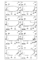
図16は、カートリッジの外観の変形例を示す説明図である。図16には、カートリッジの外観についての8つの異なる変形例を図16(A)〜図16(H)にそれぞれ図示した。本実施形態のカートリッジ20と同様の構成については、同一符号を付すと共に、説明を省略する。
[Modification of cartridge appearance]
FIG. 16 is an explanatory view showing a modified example of the appearance of the cartridge. FIG. 16 illustrates eight different modifications of the appearance of the cartridge in FIGS. 16A to 16H, respectively. The same components as those of the cartridge 20 of the present embodiment are denoted by the same reference numerals and description thereof is omitted.

図16(A)のカートリッジ20aの外殻は、楕円形または長円形の側面を有している。カートリッジ20aの正面側には、第1カートリッジ側係止部210および回路基板400が設けられている。カートリッジ20aの底面側には、インク供給口280が形成されている。カートリッジ20aの背面側には、第2カートリッジ側係止部220が形成されている。カートリッジ20aを正面側から見ると、カートリッジ20aは一定の幅を有している。   The outer shell of the cartridge 20a in FIG. 16A has an elliptical or oval side surface. A first cartridge side locking portion 210 and a circuit board 400 are provided on the front side of the cartridge 20a. An ink supply port 280 is formed on the bottom surface side of the cartridge 20a. A second cartridge side locking portion 220 is formed on the back side of the cartridge 20a. When the cartridge 20a is viewed from the front side, the cartridge 20a has a certain width.

図16(B)のカートリッジ20bは、第3面203の−Z軸方向側に第8面208が繋がっていない点を除き、本実施形態のカートリッジ20と同様である。   The cartridge 20b of FIG. 16B is the same as the cartridge 20 of the present embodiment except that the eighth surface 208 is not connected to the −Z-axis direction side of the third surface 203.

図16(C)のカートリッジ20cは、第8面208を第1面201まで延長して第7面207を省略した点を除き、本実施形態のカートリッジ20と同様である。   The cartridge 20c in FIG. 16C is the same as the cartridge 20 of this embodiment except that the eighth surface 208 is extended to the first surface 201 and the seventh surface 207 is omitted.

図16(D)のカートリッジ20dは、第2面202と第3面203との交わる部位を切り欠いた形状を有する点、および第1面201が第8面208へと傾斜させて第7面207を省略した点を除き、本実施形態のカートリッジ20と同様である。   The cartridge 20d in FIG. 16D has a shape in which a portion where the second surface 202 and the third surface 203 intersect is cut out, and the first surface 201 is inclined to the eighth surface 208 to form a seventh surface. Except for the point that 207 is omitted, it is the same as the cartridge 20 of the present embodiment.

図16(E)のカートリッジ20eは、第8面208にバネを介して回路基板400が取り付けられている点を除き、本実施形態のカートリッジ20と同様である。   The cartridge 20e in FIG. 16E is the same as the cartridge 20 of this embodiment except that the circuit board 400 is attached to the eighth surface 208 via a spring.

図16(F)に示すカートリッジ20fは、第8面208に相当する面208fが可動に構成されており、この面208fに回路基板400が設けられている点を除き、本実施形態のカートリッジ20と同様である。   The cartridge 20f shown in FIG. 16F is configured such that a surface 208f corresponding to the eighth surface 208 is movable, and the circuit board 400 is provided on the surface 208f. It is the same.

図16(G)に示すカートリッジ20gは、第8面208が第1面201まで延長されて第7面207が省略されており、さらに、第3面203の途中から第8面208とほぼ平行に切り込まれたような形状の溝が形成されている。そして、この溝によって隔てられた第8面208の2つの部位のうち、第8面に近い部位の方に、第1カートリッジ側係止部210が設けられている。この点を除き、本実施形態のカートリッジ20と同様である。   In the cartridge 20g shown in FIG. 16G, the eighth surface 208 is extended to the first surface 201, the seventh surface 207 is omitted, and the second surface 208 is almost parallel from the middle of the third surface 203. A groove having a shape that is cut into the groove is formed. Of the two parts of the eighth surface 208 separated by the groove, the first cartridge side locking portion 210 is provided on the part close to the eighth surface. Except for this point, the cartridge 20 is the same as the cartridge 20 of the present embodiment.

図16(H)に示すカートリッジ20hは、第8面208が第1面201まで延長されて第7面207が省略されており、さらに、第3面203と第1カートリッジ側係止部210とが、カートリッジ本体に対して支点を中心に回動可能に固定されたアーム212に設けられている。この点を除き、本実施形態のカートリッジ20と同様である。   In the cartridge 20h shown in FIG. 16H, the eighth surface 208 is extended to the first surface 201 and the seventh surface 207 is omitted, and the third surface 203, the first cartridge side locking portion 210, and the like. Is provided on an arm 212 that is fixed to the cartridge body so as to be rotatable about a fulcrum. Except for this point, the cartridge 20 is the same as the cartridge 20 of the present embodiment.

図16の各変形例のカートリッジ20a〜20hにはいずれも、第1カートリッジ側係止部210、第2カートリッジ側係止部220、インク供給口280および回路基板400の各々が、本実施形態のカートリッジ20に対応する位置に設けられている。これによって、各変形例のカートリッジ20a〜20hはいずれも、本実施形態のカートリッジ20との互換性を有する。   Each of the cartridges 20a to 20h in each modified example of FIG. 16 includes the first cartridge side locking portion 210, the second cartridge side locking portion 220, the ink supply port 280, and the circuit board 400. It is provided at a position corresponding to the cartridge 20. As a result, any of the cartridges 20a to 20h of each modification has compatibility with the cartridge 20 of the present embodiment.

図16の各変形例から理解できるように、カートリッジの外形の形状には、種々の変形例が考えられる。カートリッジの外形の形状が略直方体以外の形状を有している場合にも、例えば、図16(A)および図16(D)に点線で示したように、略直方体の6つの面、すなわち、図6および図7に示した第1面(底面)201、第2面(上面)202、第3面(正面)203、第4面(背面)204、第5面(左側面)205および第6面(右側面)206を、仮想的に考えることが可能である。
本明細書では、「面」(プレーン)という用語を、このような仮想的な面(仮想面、非実在面とも呼ぶ)と、図6や図7に記載したような実在面と、の両方を包含した意味で使用する。また、本明細書では、「面」という用語を、平面と曲面の両方を包含した意味で使用する。
As can be understood from the respective modifications of FIG. 16, various modifications can be considered for the outer shape of the cartridge. Even when the outer shape of the cartridge has a shape other than a substantially rectangular parallelepiped, for example, as shown by dotted lines in FIGS. 16A and 16D, six surfaces of the substantially rectangular parallelepiped, that is, The first surface (bottom surface) 201, the second surface (upper surface) 202, the third surface (front surface) 203, the fourth surface (rear surface) 204, the fifth surface (left side surface) 205 and the first surface shown in FIGS. Six sides (right side) 206 can be considered virtually.
In this specification, the term “plane” is used to refer to both such a virtual plane (also referred to as a virtual plane or a non-real plane) and a real plane as described in FIGS. 6 and 7. It is used in the meaning including. Further, in this specification, the term “surface” is used in a meaning including both a plane and a curved surface.

〔アダプターを使用したカートリッジ〕
図17は、アダプター299を使用したカートリッジ20iの構成を示す斜視図である。カートリッジ20iは、収容部材200iと、アダプター299とに分離可能に構成されている。収容部材200iは、印刷材を内部に収容する印刷材収容部200を有する。
印刷材収容部200から印刷材が無くなった場合、収容部材200iを新しいものに交換するか、印刷材収容部200に印刷材を補給することが可能である。収容部材200iの交換や、印刷材の補給を行う際には、アダプター299を再利用することが可能である。
図17のカートリッジ20iは、図6に示した本実施形態のカートリッジ20と互換性を有する。
[Cartridge using adapter]
FIG. 17 is a perspective view showing the configuration of the cartridge 20 i using the adapter 299. The cartridge 20i is configured to be separable into a housing member 200i and an adapter 299. The accommodation member 200i has a printing material accommodation unit 200 that accommodates the printing material therein.
When the printing material is exhausted from the printing material storage unit 200, it is possible to replace the storage member 200i with a new one or supply the printing material storage unit 200 with the printing material. The adapter 299 can be reused when the housing member 200i is replaced or the printing material is replenished.
The cartridge 20i in FIG. 17 is compatible with the cartridge 20 of the present embodiment shown in FIG.

カートリッジ20iの外殻22iは、収容部材200iの外殻と、アダプター299iの外殻との組み合わせによって構成される。収容部材200iは、印刷材収容部200に加え、インク流路282および発泡樹脂体284を有する。   The outer shell 22i of the cartridge 20i is configured by a combination of the outer shell of the housing member 200i and the outer shell of the adapter 299i. The storage member 200 i includes an ink flow path 282 and a foamed resin body 284 in addition to the printing material storage unit 200.

カートリッジ20iの収容部材200iは、カートリッジ20iの第2面202に相当する第2面202iを備える。収容部材200iは、カートリッジ20iの第1面201、第3〜第8面203〜208にそれぞれ対応する第1面201i、第3面203i、第4面204i、第5面(図示省略)、第6面206i、第7面207i、および第8面208iを備える。   The accommodating member 200i of the cartridge 20i includes a second surface 202i corresponding to the second surface 202 of the cartridge 20i. The housing member 200i includes a first surface 201i, a third surface 203i, a fourth surface 204i, a fifth surface (not shown), a first surface corresponding to the first surface 201 and the third to eighth surfaces 203 to 208 of the cartridge 20i. A sixth surface 206i, a seventh surface 207i, and an eighth surface 208i are provided.

第1面201iと第2面202iは、Z軸方向において対向しており、第1面201iが−Z軸方向側、第2面202iが+Z軸方向側に位置する。第3面203iと第4面204は、X軸方向において対向しており、第3面203iが+X軸方向側、第4面204iが−X軸方向側に位置する。第5面(図示省略)と第6面206iは、Y軸方向において対向しており、第5面(図示省略)が+Y軸方向側、第6面206iが−Y軸方向側に位置する。第7面207iおよび第8面208iは、第1面201iと第3面203iとを繋ぐ接続面を形成する。   The first surface 201i and the second surface 202i face each other in the Z-axis direction, and the first surface 201i is located on the −Z-axis direction side and the second surface 202i is located on the + Z-axis direction side. The third surface 203i and the fourth surface 204 face each other in the X-axis direction, the third surface 203i is positioned on the + X-axis direction side, and the fourth surface 204i is positioned on the −X-axis direction side. The fifth surface (not shown) and the sixth surface 206i face each other in the Y-axis direction, the fifth surface (not shown) is located on the + Y-axis direction side, and the sixth surface 206i is located on the −Y-axis direction side. The seventh surface 207i and the eighth surface 208i form a connection surface that connects the first surface 201i and the third surface 203i.

第7面207iは、第1面201iと直角に交わる面である。第7面207iは、Y軸およびZ軸に平行な面(YZ平面)である。段差面としての第7面207iは、第1面201iに対し立設された面である。すなわち、第7面207iは第1面201iから+Z軸方向に延びる面である。第7面207iは、第8面208iに対して−X軸方向側かつ−Z軸方向側に位置する。   The seventh surface 207i is a surface that intersects the first surface 201i at a right angle. The seventh surface 207 i is a surface (YZ plane) parallel to the Y axis and the Z axis. The seventh surface 207i as the step surface is a surface erected with respect to the first surface 201i. That is, the seventh surface 207i is a surface extending in the + Z-axis direction from the first surface 201i. The seventh surface 207i is located on the −X axis direction side and the −Z axis direction side with respect to the eighth surface 208i.

第8面208iは、第7面207iと第3面203iとを繋ぐ面である。第8面208iは、+X軸方向と−Z軸方向の成分を含む方向を向いて傾斜した斜面である。第8面208iは、第1面201iおよび第3面203iに対して傾斜した面である。第8面208iは、第5面205iおよび第6面206iと直角に交わる面である。第8面208iは、XY平面およびYZ平面に対して傾斜しており、XZ平面に対して直角に交わる。   The eighth surface 208i is a surface that connects the seventh surface 207i and the third surface 203i. The eighth surface 208i is a slope inclined toward the direction including the components in the + X axis direction and the −Z axis direction. The eighth surface 208i is a surface inclined with respect to the first surface 201i and the third surface 203i. The eighth surface 208i is a surface that intersects the fifth surface 205i and the sixth surface 206i at a right angle. The eighth surface 208i is inclined with respect to the XY plane and the YZ plane, and intersects the XZ plane at a right angle.

カートリッジ20iのアダプター299は、カートリッジ20iの第1面201、第3面203、第4面204、第5面205、第6面206、第7面207、および第8面208にそれぞれ相当する面を備える。アダプター299の面のうち、カートリッジ20iの第2面202に相当する面は、開口となっている。アダプター299の内部には、収容部材200iを受け入れる空間が形成されている。アダプター299の第1面201には、インク供給口280が設けられている。   The adapter 299 of the cartridge 20i is a surface corresponding to the first surface 201, the third surface 203, the fourth surface 204, the fifth surface 205, the sixth surface 206, the seventh surface 207, and the eighth surface 208 of the cartridge 20i. Is provided. Of the surfaces of the adapter 299, the surface corresponding to the second surface 202 of the cartridge 20i is an opening. Inside the adapter 299, a space for receiving the housing member 200i is formed. An ink supply port 280 is provided on the first surface 201 of the adapter 299.

図17のカートリッジ20iの構成は、上述したように、収容部材200iとアダプター299とに分離可能である点を除き、変形例を含め図6に示した本実施形態のカートリッジ20と同様である。なお、他の実施形態や他の変形例において、図17のカートリッジ20iのように、収容部材とアダプターとに分離可能な構成を適用しても良い。なお、図17のカートリッジ20iにおける各部の寸法や比率は、本実施形態と異なる部位もあるが、本実施形態と同様の寸法や比率にしても良い。   The configuration of the cartridge 20i of FIG. 17 is the same as that of the cartridge 20 of the present embodiment shown in FIG. 6 including the modification, except that the housing member 200i and the adapter 299 can be separated as described above. In other embodiments and other modifications, a configuration in which the housing member and the adapter can be separated as in the cartridge 20i in FIG. 17 may be applied. Note that the dimensions and ratios of the respective parts of the cartridge 20i in FIG. 17 may be different from those of the present embodiment, but may be the same dimensions and ratios as those of the present embodiment.

図18は、アダプターを使用したカートリッジ20jの構成を示す斜視図である。カートリッジ20jは、収容部材200jと、アダプター299jとに分離可能に構成されている。収容部材200jは、印刷材を内部に収容する印刷材収容部200を有する。印刷材収容部200から印刷材が無くなった場合、収容部材200jを新しいものに交換するか、印刷材収容部200に印刷材を補給することが可能である。収容部材200jの交換や、印刷材の補給を行う際には、アダプター299jを再利用することが可能である。図18のカートリッジ20jは、図6に示した本実施形態のカートリッジ20と互換性を有する。   FIG. 18 is a perspective view showing a configuration of a cartridge 20j using an adapter. The cartridge 20j is configured to be separable into a housing member 200j and an adapter 299j. The accommodation member 200j has a printing material accommodation unit 200 that accommodates the printing material therein. When the printing material is exhausted from the printing material storage unit 200, it is possible to replace the storage member 200j with a new one or supply the printing material storage unit 200 with the printing material. The adapter 299j can be reused when the housing member 200j is replaced or the printing material is supplied. The cartridge 20j in FIG. 18 is compatible with the cartridge 20 of the present embodiment shown in FIG.

カートリッジ20jの外殻22jは、収容部材200jの外殻と、アダプター299jの外殻との組み合わせによって構成される。収容部材200jは、印刷材収容部200およびインク供給口280を有する。   The outer shell 22j of the cartridge 20j is configured by a combination of the outer shell of the housing member 200j and the outer shell of the adapter 299j. The storage member 200j includes a printing material storage unit 200 and an ink supply port 280.

カートリッジ20jの収容部材200jは、カートリッジ20jの第2面202および第6面206にそれぞれ相当する第2面202jおよび第6面206jを備える。収容部材200jは、カートリッジ20jの第1面201、第3面203、第4面204、第5面205、第7面207、および第8面208にそれぞれ対応する第1面201j、第3面203j、第4面204j、第5面(図示省略)、第7面207j、および第8面208jを備える。   The accommodating member 200j of the cartridge 20j includes a second surface 202j and a sixth surface 206j corresponding to the second surface 202 and the sixth surface 206 of the cartridge 20j, respectively. The housing member 200j includes a first surface 201j and a third surface corresponding to the first surface 201, the third surface 203, the fourth surface 204, the fifth surface 205, the seventh surface 207, and the eighth surface 208 of the cartridge 20j, respectively. 203j, a fourth surface 204j, a fifth surface (not shown), a seventh surface 207j, and an eighth surface 208j.

第1面201jと第2面202jは、Z軸方向において対向しており、第1面201jが−Z軸方向側、第2面202jが+Z軸方向側に位置する。第3面203jと第4面204jは、X軸方向において対向しており、第3面203jが+X軸方向側、第4面204jが−X軸方向側に位置する。第5面(図示省略)と第6面206jは、Y軸方向において対向しており、第5面(図示省略)が+Y軸方向側、第6面206jが−Y軸方向側に位置する。第7面207jおよび第8面208jは、第1面201jと第3面203jとを繋ぐ接続面を形成する。   The first surface 201j and the second surface 202j are opposed to each other in the Z-axis direction, and the first surface 201j is located on the −Z-axis direction side and the second surface 202j is located on the + Z-axis direction side. The third surface 203j and the fourth surface 204j face each other in the X-axis direction, the third surface 203j is positioned on the + X-axis direction side, and the fourth surface 204j is positioned on the −X-axis direction side. The fifth surface (not shown) and the sixth surface 206j face each other in the Y-axis direction, the fifth surface (not shown) is located on the + Y-axis direction side, and the sixth surface 206j is located on the −Y-axis direction side. The seventh surface 207j and the eighth surface 208j form a connection surface that connects the first surface 201j and the third surface 203j.

第7面207jは、第1面201jと直角に交わる面である。第7面207jは、Y軸およびZ軸に平行な面(YZ平面)である。段差面としての第7面207jは、第1面201jに対し立設された面である。すなわち、第7面207jは第1面201jから+Z軸方向に延びる面である。第7面207jは第8面208jに対して−X軸方向側かつ−Z軸方向側に位置する。   The seventh surface 207j is a surface that intersects the first surface 201j at a right angle. The seventh surface 207j is a surface (YZ plane) parallel to the Y axis and the Z axis. The seventh surface 207j as the step surface is a surface erected with respect to the first surface 201j. That is, the seventh surface 207j is a surface extending in the + Z-axis direction from the first surface 201j. The seventh surface 207j is located on the −X axis direction side and the −Z axis direction side with respect to the eighth surface 208j.

第8面208jは、第7面207jと第3面203jとを繋ぐ面である。第8面208jは、+X軸方向と−Z軸方向の成分を含む方向を向いて傾斜した斜面である。第8面208jは、第1面201jおよび第3面203jに対して傾斜した面である。第8面208jは、第5面205jおよび第6面206jと直角に交わる面である。第8面208jは、XY平面およびYZ平面に対して傾斜しており、XZ平面に対して直角に交わる。   The eighth surface 208j is a surface connecting the seventh surface 207j and the third surface 203j. The eighth surface 208j is a slope inclined toward the direction including the components in the + X axis direction and the −Z axis direction. The eighth surface 208j is a surface inclined with respect to the first surface 201j and the third surface 203j. The eighth surface 208j is a surface that intersects the fifth surface 205j and the sixth surface 206j at a right angle. The eighth surface 208j is inclined with respect to the XY plane and the YZ plane, and intersects the XZ plane at a right angle.

カートリッジ20jのアダプター299jは、カートリッジ20jの第1面201、第3面203、第4面204、および第5面205に相当する面を備えている。アダプター299jの面のうち、カートリッジ20jの第2面202および第6面206に相当する面は、開口となっている。アダプター299jの内部には、収容部材200jを受け入れる空間が形成されている。アダプター299jは、第1面201の一部に開口を有し、その開口を通して、収容部材200jのインク供給口280を露出させてインク供給管640に接続させる。   The adapter 299j of the cartridge 20j includes surfaces corresponding to the first surface 201, the third surface 203, the fourth surface 204, and the fifth surface 205 of the cartridge 20j. Of the surfaces of the adapter 299j, the surfaces corresponding to the second surface 202 and the sixth surface 206 of the cartridge 20j are openings. A space for receiving the housing member 200j is formed inside the adapter 299j. The adapter 299j has an opening in a part of the first surface 201, through which the ink supply port 280 of the storage member 200j is exposed and connected to the ink supply tube 640.

図18のカートリッジ20jの構成は、上述したように、収容部材200jとアダプター299jとに分離可能である点を除き、変形例を含め図6に示した本実施形態のカートリッジ20と同様である。なお、他の実施形態や他の変形例において、図18のカートリッジ20jのように、収容部材とアダプターとに分離可能な構成を適用しても良い。   The configuration of the cartridge 20j of FIG. 18 is the same as that of the cartridge 20 of the present embodiment shown in FIG. 6 including the modified example, except that the housing member 200j and the adapter 299j can be separated as described above. In other embodiments and other modifications, a configuration in which the housing member and the adapter can be separated as in the cartridge 20j in FIG. 18 may be applied.

なお、図18のカートリッジ20jでは、本実施形態(図6を参照)と比較して、第1カートリッジ側係止部210の形状が簡略化されているが、本実施形態と同様の形状としても良い。また、図18のカートリッジ20jにおける各部の寸法や比率は、本実施形態と異なる部位もあるが、本実施形態と同様の寸法や比率にしても良い。また、図18のカートリッジ20jでは、突出部260が省略されているが、本実施形態と同様に突出部260を設けても良い。   In the cartridge 20j in FIG. 18, the shape of the first cartridge side locking portion 210 is simplified as compared with the present embodiment (see FIG. 6). good. Further, the dimensions and ratios of the respective parts in the cartridge 20j in FIG. 18 may be different from those of the present embodiment, but may be the same dimensions and ratios as those of the present embodiment. Further, in the cartridge 20j of FIG. 18, the protruding portion 260 is omitted, but the protruding portion 260 may be provided as in the present embodiment.

図19は、アダプターを使用したカートリッジ20kの構成を示す斜視図である。カートリッジ20kは、アダプター299kと、外部タンク200Tと、チューブ200Lと、補助アダプター200Sとを備える。カートリッジ20kのアダプター299kは、変形例も含め、図18のアダプター299jと同様の構成である。   FIG. 19 is a perspective view showing a configuration of a cartridge 20k using an adapter. The cartridge 20k includes an adapter 299k, an external tank 200T, a tube 200L, and an auxiliary adapter 200S. The adapter 299k of the cartridge 20k has the same configuration as the adapter 299j of FIG.

カートリッジ20kの外部タンク200Tは、印刷材を内部に収容する。本実施形態では、外部タンク200Tは、図1に示すプリンター50の外部に設置される。外部タンク200Tの印刷材は、チューブ200Lを介して補助アダプター200Sに供給される。
カートリッジ20kの補助アダプター200Sは、インク供給口280に相当するインク供給口280kを有する。
The external tank 200T of the cartridge 20k accommodates the printing material inside. In the present embodiment, the external tank 200T is installed outside the printer 50 shown in FIG. The printing material of the external tank 200T is supplied to the auxiliary adapter 200S through the tube 200L.
The auxiliary adapter 200S of the cartridge 20k has an ink supply port 280k corresponding to the ink supply port 280.

外部タンク200T、補助アダプター200S、およびチューブ200Lは、インクを収容する収容部材200kとして機能する。つまり、図中に点線で示すように、図19のカートリッジ20kは、収容部材200kを有するとみなすことができる。カートリッジ20kの外殻22kは、仮想的な収容部材200kの外殻と、アダプター299kの外殻との組み合わせによって構成される。   The external tank 200T, the auxiliary adapter 200S, and the tube 200L function as a storage member 200k that stores ink. That is, as indicated by a dotted line in the drawing, the cartridge 20k in FIG. The outer shell 22k of the cartridge 20k is configured by a combination of the outer shell of the virtual housing member 200k and the outer shell of the adapter 299k.

このように、図19のカートリッジ20kは、図17のカートリッジ20iや図18のカートリッジ20jと同様に、収容部材200kとアダプター299jとに分離可能に構成されていると捉えることができる。外部タンク200Tから印刷材が無くなった場合、外部タンク200Tを新しいものに交換するか、外部タンク200Tに印刷材を補給することが可能である。外部タンク200Tの交換や、印刷材の補給を行う際には、アダプター299kを再利用することが可能である。図19のカートリッジ20kは、図6に示した本実施形態のカートリッジ20と互換性を有する。   As described above, the cartridge 20k in FIG. 19 can be regarded as being configured to be separable into the housing member 200k and the adapter 299j, similarly to the cartridge 20i in FIG. 17 and the cartridge 20j in FIG. When the printing material runs out of the external tank 200T, it is possible to replace the external tank 200T with a new one or supply the printing material to the external tank 200T. The adapter 299k can be reused when the external tank 200T is replaced or the printing material is replenished. The cartridge 20k of FIG. 19 is compatible with the cartridge 20 of the present embodiment shown in FIG.

図19のカートリッジ20kの構成は、上述したように、収容部材200kとアダプター299kとに分離可能である点を除き、変形例を含め図6に示した本実施形態のカートリッジ20と同様である。なお、他の実施形態や他の変形例において、図19のカートリッジ20kのように、収容部材とアダプターとに分離可能な構成を適用しても良い。   The configuration of the cartridge 20k of FIG. 19 is the same as that of the cartridge 20 of the present embodiment shown in FIG. 6 including the modification except that the cartridge 20k can be separated into the housing member 200k and the adapter 299k as described above. In other embodiments and other modifications, a configuration in which the housing member and the adapter can be separated as in the cartridge 20k of FIG. 19 may be applied.

〔回路基板400および端子配列に関する変形例〕
上述した実施形態では、カートリッジ20に回路基板400が設けられているが、他の実施形態では、カートリッジ20に回路基板400が設けられていなくても良い。すなわち、第8面208上に直接カートリッジ側端子を形成しても良い。この場合、カートリッジ側斜面408は、第8面208の表面となる。
[Variation regarding circuit board 400 and terminal arrangement]
In the above-described embodiment, the circuit board 400 is provided on the cartridge 20. However, in other embodiments, the circuit board 400 may not be provided on the cartridge 20. That is, the cartridge side terminal may be formed directly on the eighth surface 208. In this case, the cartridge side inclined surface 408 is the surface of the eighth surface 208.

また、回路基板400上に形成されていた配線の一部や記憶装置420を、第8面208以外の面に設けても良い。たとえば、回路基板400よりも面積が大きいフレキシブルプリント基板上に、配線、記憶装置420、カートリッジ側端子431〜439を設け、フレキシブルプリント基板を折り曲げて、第8面上にカートリッジ側端子431〜439が配置されるようにし、第8面と隣接する第5面205上に配線の一部や記憶装置420が配置されるようにしても良い。   In addition, part of the wiring formed on the circuit board 400 and the storage device 420 may be provided on a surface other than the eighth surface 208. For example, wiring, a storage device 420, and cartridge side terminals 431 to 439 are provided on a flexible printed circuit board having a larger area than the circuit board 400, and the flexible printed circuit board is bent, and the cartridge side terminals 431 to 439 are formed on the eighth surface. Alternatively, a part of the wiring or the storage device 420 may be disposed on the fifth surface 205 adjacent to the eighth surface.

また、カートリッジ側端子および装置側端子の配列は、2列ではなく、1列であっても良いし、3列以上であっても良い。   Further, the arrangement of the cartridge side terminals and the apparatus side terminals may be one row instead of two rows, or three or more rows.

また、カートリッジ側端子431〜439の形状や配列は、図11(A)に示したものに限られない。
図20は、カートリッジ側端子の形状の変形例を示す図である。
図20に示す変形例の回路基板400A,400B,400Cは、カートリッジ側端子431〜439の表面形状が異なる点を除き、図11(A)の回路基板400と同様である。
Further, the shape and arrangement of the cartridge side terminals 431 to 439 are not limited to those shown in FIG.
FIG. 20 is a diagram illustrating a modified example of the shape of the cartridge side terminal.
Circuit boards 400A, 400B, and 400C of the modification shown in FIG. 20 are the same as circuit board 400 of FIG. 11A except that the surface shapes of cartridge side terminals 431 to 439 are different.

図20(A)の回路基板400Aでは、カートリッジ側端子431〜439の表面形状は、図11(A)の回路基板400のように略長方形ではなく、不規則的な多角形状である。   In the circuit board 400A of FIG. 20A, the surface shape of the cartridge side terminals 431 to 439 is not a substantially rectangular shape as in the circuit board 400 of FIG.

図20(B)の回路基板400Bでは、カートリッジ側端子431〜439の表面形状は、図11(A)の回路基板400のように略長方形ではなく、不規則的な直線や曲線で囲まれた形状である。   In the circuit board 400B of FIG. 20B, the surface shapes of the cartridge side terminals 431 to 439 are not substantially rectangular like the circuit board 400 of FIG. 11A, but are surrounded by irregular straight lines and curves. Shape.

図20(C)の回路基板400Cでは、カートリッジ側端子431〜439の表面形状は、所定の幅を有する直線状であって、それぞれ同じ形状である。これらカートリッジ側端子431〜439は、その幅方向に一列に配列されている。カートリッジ側端子(装着検出端子)435,439は、カートリッジ側端子431〜439が並ぶ配列の両端にそれぞれ配置されている。カートリッジ側端子(装着検出端子)431は、カートリッジ側端子(装着検出端子)435とカートリッジ側端子(電源端子)436との間に配置されている。カートリッジ側端子434(装着検出端子)は、カートリッジ側端子439(装着検出端子)とカートリッジ側端子(電源端子)438との間に配置されている。   In the circuit board 400C of FIG. 20C, the surface shapes of the cartridge side terminals 431 to 439 are linear shapes having a predetermined width, and are the same shape. These cartridge side terminals 431 to 439 are arranged in a line in the width direction. The cartridge side terminals (mounting detection terminals) 435 and 439 are arranged at both ends of the array in which the cartridge side terminals 431 to 439 are arranged. The cartridge side terminal (mounting detection terminal) 431 is disposed between the cartridge side terminal (mounting detection terminal) 435 and the cartridge side terminal (power supply terminal) 436. The cartridge side terminal 434 (mounting detection terminal) is disposed between the cartridge side terminal 439 (mounting detection terminal) and the cartridge side terminal (power supply terminal) 438.

図20に示す変形例の回路基板400A,400B,400Cにおいても、カートリッジ側端子431〜439に対応する装置側端子との接触部cpの配置は、図11(A)の本実施形態と同様である。このように、個々の端子の表面形状は、接触部cpの配置が同一である限り、種々の変形が可能である。   Also in the circuit boards 400A, 400B, and 400C of the modified example shown in FIG. 20, the arrangement of the contact portions cp with the device side terminals corresponding to the cartridge side terminals 431 to 439 is the same as that of the present embodiment of FIG. is there. As described above, the surface shape of each terminal can be variously modified as long as the arrangement of the contact portions cp is the same.

〔その他の変形例〕
上述した実施形態における構成要素のうち、特定の目的、作用、効果に関係の無い構成要素は省略可能である。例えば、カートリッジ20の記憶装置420に代えて、他の電気デバイスを搭載しても良い。
[Other variations]
Among the constituent elements in the above-described embodiments, constituent elements that are not related to a specific purpose, function, and effect can be omitted. For example, instead of the storage device 420 of the cartridge 20, another electric device may be mounted.

上述した実施形態における各種の部材は、それぞれ独立した部材として構成する必要はなく、必要に応じて複数の部材を一体成形しても良い。また、上述した実施形態における1つの部材を、複数の部材の組み合わせによって構成しても良い。   The various members in the above-described embodiment do not need to be configured as independent members, and a plurality of members may be integrally formed as necessary. Moreover, you may comprise one member in embodiment mentioned above by the combination of a some member.

本発明は、インクジェットプリンターおよびそのインクカートリッジに限らず、インク以外の他の液体を噴射する任意の液体噴射装置およびその液体収容容器にも適用することができる。例えば、以下のような各種の液体噴射装置およびその液体収容容器に適用可能である。
・ファクシミリ装置等の画像記録装置・液晶ディスプレー等の画像表示装置用のカラーフィルタの製造に用いられる色材噴射装置・有機EL(Electro Luminescence)ディスプレーや、面発光ディスプレー (Field Emission Display、FED)等の電極形成に用いられる電極材噴射装置・バイオチップ製造に用いられる生体有機物を含む液体を噴射する液体噴射装置・精密ピペットとしての試料噴射装置・潤滑油の噴射装置・樹脂液の噴射装置・時計やカメラ等の精密機械にピンポイントで潤滑油を噴射する液体噴射装置・光通信素子等に用いられる微小半球レンズ(光学レンズ)などを形成するために紫外線硬化樹脂液等の透明樹脂液を基板上に噴射する液体噴射装置・基板などをエッチングするために酸性またはアルカリ性のエッチング液を噴射する液体噴射装置・他の任意の微小量の液滴を吐出させる液体噴射ヘッドを備える液体噴射装置
The present invention can be applied not only to an ink jet printer and its ink cartridge, but also to any liquid ejecting apparatus that ejects liquid other than ink and its liquid container. For example, the present invention can be applied to the following various liquid ejecting apparatuses and the liquid storage containers.
・ Image recording devices such as facsimile devices ・ Color material injection devices used in the production of color filters for image display devices such as liquid crystal displays ・ Organic EL (Electro Luminescence) displays, surface emission displays (Field Emission Displays, FEDs), etc. Electrode material injection device used for electrode formation, Liquid injection device for injecting liquid containing bio-organic matter used for biochip manufacturing, Sample injection device as precision pipette, Lubricating oil injection device, Resin liquid injection device, Clock Transparent resin liquid such as UV curable resin liquid is used to form micro hemispherical lenses (optical lenses) used for liquid injection devices and optical communication elements that inject lubricating oil onto precision machines such as cameras and cameras. Liquid jetting device that injects acidic or alkaline etching solution to etch liquid jetting devices and substrates A liquid ejecting apparatus including a liquid ejecting head for ejecting droplets of equipment and any other small quantity

なお、「液滴」とは、液体噴射装置から吐出される液体の状態をいい、粒状の液体、涙状の液体の他、糸状に尾を引く液体も含むものとする。また、ここでいう「液体」とは、液体噴射装置が噴射させることができるような材料であれば良い。例えば、「液体」は、物質が液相であるときの状態の材料であれば良く、粘性の高いまたは低い液状態の材料、および、ゾル、ゲル水、その他の無機溶剤、有機溶剤、溶液、液状樹脂、液状金属(金属融液)のような液状態の材料も「液体」に含まれる。また、物質の一状態としての液体のみならず、顔料や金属粒子などの固形物からなる機能材料の粒子が溶媒に溶解、分散または混合されたものなども「液体」に含まれる。また、液体の代表的な例としては上記実施形態で説明したようなインクや液晶等が挙げられる。ここで、インクとは一般的な水性インクおよび油性インク並びにジェルインク、ホットメルトインク等の各種の液体状組成物を包含するものとする。   The “droplet” refers to a state of liquid ejected from the liquid ejecting apparatus, and includes a liquid that pulls a tail in a string shape in addition to a granular liquid and a tear-like liquid. The “liquid” here may be any material that can be ejected by the liquid ejecting apparatus. For example, the “liquid” may be a material in a state when the substance is in a liquid phase, and a material in a liquid state having high or low viscosity, and sol, gel water, other inorganic solvents, organic solvents, solutions, Liquid materials such as liquid resins and liquid metals (metal melts) are also included in the “liquid”. Further, “liquid” includes not only a liquid as one state of a substance but also a liquid obtained by dissolving, dispersing or mixing particles of a functional material made of a solid such as a pigment or metal particles in a solvent. Further, representative examples of the liquid include ink and liquid crystal as described in the above embodiment. Here, the ink includes various liquid compositions such as general water-based ink and oil-based ink, gel ink, and hot-melt ink.

20,20a〜k…カートリッジ 50…プリンター(印刷装置) 201…第1面 202…第2面 203…第3面 204…第4面 205…第5面 206…第6面 280,280k…インク供給口(印刷材供給口) 284…発泡樹脂体(フィルター) 640…インク供給管(印刷材供給管) 644…多孔体フィルター(フィルター) L…寸法,有効寸法 M…寸法,有効寸法 S…面積,有効面積 T…面積,有効面積 H…高さ W…幅 D…奥行き     20, 20a-k ... cartridge 50 ... printer (printing apparatus) 201 ... first surface 202 ... second surface 203 ... third surface 204 ... fourth surface 205 ... fifth surface 206 ... sixth surface 280, 280k ... ink supply Port (printing material supply port) 284 ... Foamed resin body (filter) 640 ... Ink supply pipe (printing material supply pipe) 644 ... Porous filter (filter) L ... Dimensions, effective dimensions M ... Dimensions, effective dimensions S ... Area, Effective area T ... Area, Effective area H ... Height W ... Width D ... Depth

Claims (8)

印刷装置に設けられた印刷材供給管に接続される印刷材供給口を供えたカートリッジであって、
前記印刷材供給口の有効面積は、前記印刷材供給管の有効面積の1倍以上、5倍以下である、カートリッジ。
A cartridge provided with a printing material supply port connected to a printing material supply pipe provided in the printing apparatus,
The cartridge, wherein an effective area of the printing material supply port is 1 to 5 times an effective area of the printing material supply pipe.
前記印刷材供給口の有効面積は、前記印刷材供給管の有効面積の2倍以上、4.5倍以下である、請求項1に記載のカートリッジ。   The cartridge according to claim 1, wherein an effective area of the printing material supply port is not less than 2 times and not more than 4.5 times an effective area of the printing material supply pipe. 前記印刷材供給口の有効面積は、前記印刷材供給管の有効面積の3倍以上、4倍以下である、請求項1に記載のカートリッジ。   The cartridge according to claim 1, wherein an effective area of the printing material supply port is not less than 3 times and not more than 4 times an effective area of the printing material supply pipe. 前記カートリッジは、
互いに対向する第1面及び第2面と、
前記第2面及び前記第1面と交差し、互いに対向する第3面及び第4面と、
前記第1面乃至前記第4面と交差し、互いに対向する第5面及び第6面と、を有し、
前記印刷材供給口は、前記第1面に設けられており、
前記第1面と前記第2面との間の距離を高さとし、前記第3面と前記第4面との間の距離を奥行きとし、前記第5面と前記第6面との間の距離を幅とすると、
前記奥行きは前記高さよりも大きく、前記高さは前記幅よりも大きく、
前記印刷材供給口の前記奥行き方向の有効寸法は、前記印刷材供給管の前記奥行き方向の有効寸法の1倍以上、5倍以下である、請求項1に記載のカートリッジ。
The cartridge is
A first surface and a second surface facing each other;
A third surface and a fourth surface intersecting the second surface and the first surface and facing each other;
A fifth surface and a sixth surface intersecting the first surface to the fourth surface and facing each other,
The printing material supply port is provided on the first surface,
The distance between the first surface and the second surface is the height, the distance between the third surface and the fourth surface is the depth, and the distance between the fifth surface and the sixth surface Is the width,
The depth is greater than the height, and the height is greater than the width;
2. The cartridge according to claim 1, wherein an effective dimension of the printing material supply port in the depth direction is 1 to 5 times an effective dimension of the printing material supply pipe in the depth direction.
前記カートリッジは、
互いに対向する第1面及び第2面と、
前記第1面及び前記第2面と交差し、互いに対向する第3面及び第4面と、
前記第1面乃至前記第4面と交差し、互いに対向する第5面及び第6面と、を有し、
前記印刷材供給口は、前記第1面に設けられており、
前記第1面と前記第2面との間の距離を高さとし、前記第3面と前記第4面との間の距離を奥行きとし、前記第5面と前記第6面との間の距離を幅とすると、
前記奥行きは前記高さ及び前記幅よりも大きく、前記高さは前記幅よりも大きく、
前記印刷材供給口の前記奥行き方向の有効寸法は、前記印刷材供給管の前記奥行き方向の有効寸法の1.5倍以上、4倍以下である、請求項1に記載のカートリッジ。
The cartridge is
A first surface and a second surface facing each other;
A third surface and a fourth surface intersecting the first surface and the second surface and facing each other;
A fifth surface and a sixth surface intersecting the first surface to the fourth surface and facing each other,
The printing material supply port is provided on the first surface,
The distance between the first surface and the second surface is the height, the distance between the third surface and the fourth surface is the depth, and the distance between the fifth surface and the sixth surface Is the width,
The depth is greater than the height and the width, and the height is greater than the width;
2. The cartridge according to claim 1, wherein an effective dimension in the depth direction of the printing material supply port is 1.5 to 4 times an effective dimension in the depth direction of the printing material supply pipe.
前記カートリッジは、
互いに対向する第1面及び第2面と、
前記第1面及び前記第2面と交差し、互いに対向する第3面及び第4面と、
前記第1面乃至前記第4面と交差し、互いに対向する第5面及び第6面と、を有し、
前記印刷材供給口は、前記第1面に設けられており、
前記第1面と前記第1面との間の距離を高さとし、前記第3面と前記第4面との間の距離を奥行きとし、前記第5面と前記第6面との間の距離を幅とすると、
前記奥行きは前記高さ及び前記幅よりも大きく、前記高さは前記幅よりも大きく、
前記印刷材供給口の前記奥行き方向の有効寸法は、前記印刷材供給管の前記奥行き方向の有効寸法の2倍以上、3倍以下である、請求項1に記載のカートリッジ。
The cartridge is
A first surface and a second surface facing each other;
A third surface and a fourth surface intersecting the first surface and the second surface and facing each other;
A fifth surface and a sixth surface intersecting the first surface to the fourth surface and facing each other,
The printing material supply port is provided on the first surface,
The distance between the first surface and the first surface is the height, the distance between the third surface and the fourth surface is the depth, and the distance between the fifth surface and the sixth surface Is the width,
The depth is greater than the height and the width, and the height is greater than the width;
2. The cartridge according to claim 1, wherein an effective dimension of the printing material supply port in the depth direction is two to three times an effective dimension of the printing material supply pipe in the depth direction.
前記印刷材供給口及び前記印刷材供給管の有効面積は、前記印刷材供給口及び前記印刷材供給管内に設けられたフィルターの有効面積によって規定される、請求項1乃至6のいずれかに記載のカートリッジ。   The effective area of the printing material supply port and the printing material supply pipe is defined by an effective area of a filter provided in the printing material supply port and the printing material supply pipe. Cartridge. 前記印刷材供給口及び前記印刷材供給管の前記奥行き方向の有効寸法は、前記印刷材供給口及び前記印刷材供給管内に設けられたフィルターの前記奥行き方向の有効寸法によって規定される、請求項3乃至6のいずれかに記載のカートリッジ。   The effective dimension in the depth direction of the printing material supply port and the printing material supply pipe is defined by the effective dimension in the depth direction of a filter provided in the printing material supply port and the printing material supply pipe. The cartridge according to any one of 3 to 6.
JP2012046947A 2012-03-02 2012-03-02 Cartridge Withdrawn JP2013180523A (en)

Priority Applications (4)

Application Number Priority Date Filing Date Title
JP2012046947A JP2013180523A (en) 2012-03-02 2012-03-02 Cartridge
CN 201320095230 CN203228502U (en) 2012-03-02 2013-03-01 Cartridge
CN2013100662229A CN103287110A (en) 2012-03-02 2013-03-01 Cartridge
US13/782,457 US8967778B2 (en) 2012-03-02 2013-03-01 Cartridge

Applications Claiming Priority (1)

Application Number Priority Date Filing Date Title
JP2012046947A JP2013180523A (en) 2012-03-02 2012-03-02 Cartridge

Publications (2)

Publication Number Publication Date
JP2013180523A true JP2013180523A (en) 2013-09-12
JP2013180523A5 JP2013180523A5 (en) 2015-04-16

Family

ID=49042610

Family Applications (1)

Application Number Title Priority Date Filing Date
JP2012046947A Withdrawn JP2013180523A (en) 2012-03-02 2012-03-02 Cartridge

Country Status (3)

Country Link
US (1) US8967778B2 (en)
JP (1) JP2013180523A (en)
CN (2) CN103287110A (en)

Cited By (1)

* Cited by examiner, † Cited by third party
Publication number Priority date Publication date Assignee Title
WO2022196482A1 (en) * 2021-03-19 2022-09-22 セイコーエプソン株式会社 Cartridge

Families Citing this family (4)

* Cited by examiner, † Cited by third party
Publication number Priority date Publication date Assignee Title
JP2013180523A (en) * 2012-03-02 2013-09-12 Seiko Epson Corp Cartridge
JP6531551B2 (en) * 2014-12-02 2019-06-19 セイコーエプソン株式会社 Liquid supply unit and liquid supply system
JP6665649B2 (en) 2016-04-15 2020-03-13 セイコーエプソン株式会社 cartridge
NL2021052B1 (en) * 2018-06-04 2019-12-11 Mevam Bv Add-on module for a printer cartridge and a printer

Citations (2)

* Cited by examiner, † Cited by third party
Publication number Priority date Publication date Assignee Title
JP2002331681A (en) * 2001-05-10 2002-11-19 Canon Inc Liquid container
JP2008094076A (en) * 2006-09-11 2008-04-24 Canon Inc Ink tank and inkjet recording device

Family Cites Families (9)

* Cited by examiner, † Cited by third party
Publication number Priority date Publication date Assignee Title
US5844578A (en) * 1990-01-30 1998-12-01 Seiko Epson Corporation Ink-jet recording apparatus and ink tank cartridge thereof
CA2272165C (en) * 1992-07-31 2003-10-14 Canon Kabushiki Kaisha Liquid storing container for recording apparatus
JP3733266B2 (en) * 1999-10-04 2006-01-11 キヤノン株式会社 Liquid storage container
JP2002137410A (en) * 2000-11-02 2002-05-14 Canon Inc Liquid ejection recording head
JP3796439B2 (en) * 2001-02-09 2006-07-12 キヤノン株式会社 Liquid storage container
JP4058436B2 (en) 2003-12-26 2008-03-12 キヤノン株式会社 Ink storage container
JP2007210186A (en) * 2006-02-09 2007-08-23 Brother Ind Ltd Needle and method for manufacturing needle
US7735983B2 (en) * 2007-02-28 2010-06-15 Eastman Kodak Company Ink jet ink cartridge with vented wick
JP2013180523A (en) * 2012-03-02 2013-09-12 Seiko Epson Corp Cartridge

Patent Citations (2)

* Cited by examiner, † Cited by third party
Publication number Priority date Publication date Assignee Title
JP2002331681A (en) * 2001-05-10 2002-11-19 Canon Inc Liquid container
JP2008094076A (en) * 2006-09-11 2008-04-24 Canon Inc Ink tank and inkjet recording device

Cited By (1)

* Cited by examiner, † Cited by third party
Publication number Priority date Publication date Assignee Title
WO2022196482A1 (en) * 2021-03-19 2022-09-22 セイコーエプソン株式会社 Cartridge

Also Published As

Publication number Publication date
CN103287110A (en) 2013-09-11
US20130229469A1 (en) 2013-09-05
CN203228502U (en) 2013-10-09
US8967778B2 (en) 2015-03-03

Similar Documents

Publication Publication Date Title
US9950537B2 (en) Cartridge and printing material supply system
JP6443480B2 (en) cartridge
US20140368585A1 (en) Cartridge and printing material supply system
US9039153B2 (en) Printing apparatus and printing material supply system
JP6028424B2 (en) Printing material supply system and cartridge thereof
EP2614960B1 (en) Cartridge and printing material supply system
JP5682732B2 (en) cartridge
JP2013180523A (en) Cartridge
JP6528564B2 (en) Liquid supply unit
JP5957891B2 (en) Cartridge and printing material supply system
JP5532154B2 (en) Cartridge and printing material supply system
JP2014014948A (en) Cartridge
JP5880054B2 (en) Printing apparatus and printing material supply system
JP2013180522A (en) Cartridge
JP5888362B2 (en) Printing apparatus and printing material supply system
JP6090418B2 (en) cartridge
JP5532155B2 (en) Cartridge and printing material supply system
JP2016132109A (en) Liquid supply unit and liquid jet system

Legal Events

Date Code Title Description
A621 Written request for application examination

Free format text: JAPANESE INTERMEDIATE CODE: A621

Effective date: 20150302

A521 Written amendment

Free format text: JAPANESE INTERMEDIATE CODE: A523

Effective date: 20150303

A977 Report on retrieval

Free format text: JAPANESE INTERMEDIATE CODE: A971007

Effective date: 20151211

A131 Notification of reasons for refusal

Free format text: JAPANESE INTERMEDIATE CODE: A131

Effective date: 20151215

A761 Written withdrawal of application

Free format text: JAPANESE INTERMEDIATE CODE: A761

Effective date: 20160129