WO2017110902A1 - 高圧容器および高圧容器の製造方法 - Google Patents
高圧容器および高圧容器の製造方法 Download PDFInfo
- Publication number
- WO2017110902A1 WO2017110902A1 PCT/JP2016/088163 JP2016088163W WO2017110902A1 WO 2017110902 A1 WO2017110902 A1 WO 2017110902A1 JP 2016088163 W JP2016088163 W JP 2016088163W WO 2017110902 A1 WO2017110902 A1 WO 2017110902A1
- Authority
- WO
- WIPO (PCT)
- Prior art keywords
- carbon fiber
- fiber bundle
- composite carbon
- composite
- thermosetting resin
- Prior art date
- Legal status (The legal status is an assumption and is not a legal conclusion. Google has not performed a legal analysis and makes no representation as to the accuracy of the status listed.)
- Ceased
Links
Images




Classifications
-
- F—MECHANICAL ENGINEERING; LIGHTING; HEATING; WEAPONS; BLASTING
- F17—STORING OR DISTRIBUTING GASES OR LIQUIDS
- F17C—VESSELS FOR CONTAINING OR STORING COMPRESSED, LIQUEFIED OR SOLIDIFIED GASES; FIXED-CAPACITY GAS-HOLDERS; FILLING VESSELS WITH, OR DISCHARGING FROM VESSELS, COMPRESSED, LIQUEFIED, OR SOLIDIFIED GASES
- F17C1/00—Pressure vessels, e.g. gas cylinder, gas tank, replaceable cartridge
- F17C1/02—Pressure vessels, e.g. gas cylinder, gas tank, replaceable cartridge involving reinforcing arrangements
- F17C1/04—Protecting sheathings
- F17C1/06—Protecting sheathings built-up from wound-on bands or filamentary material, e.g. wires
-
- B—PERFORMING OPERATIONS; TRANSPORTING
- B29—WORKING OF PLASTICS; WORKING OF SUBSTANCES IN A PLASTIC STATE IN GENERAL
- B29C—SHAPING OR JOINING OF PLASTICS; SHAPING OF MATERIAL IN A PLASTIC STATE, NOT OTHERWISE PROVIDED FOR; AFTER-TREATMENT OF THE SHAPED PRODUCTS, e.g. REPAIRING
- B29C53/00—Shaping by bending, folding, twisting, straightening or flattening; Apparatus therefor
- B29C53/56—Winding and joining, e.g. winding spirally
- B29C53/58—Winding and joining, e.g. winding spirally helically
- B29C53/581—Winding and joining, e.g. winding spirally helically using sheets or strips consisting principally of plastics material
- B29C53/582—Winding and joining, e.g. winding spirally helically using sheets or strips consisting principally of plastics material comprising reinforcements, e.g. wires, threads
-
- B—PERFORMING OPERATIONS; TRANSPORTING
- B29—WORKING OF PLASTICS; WORKING OF SUBSTANCES IN A PLASTIC STATE IN GENERAL
- B29C—SHAPING OR JOINING OF PLASTICS; SHAPING OF MATERIAL IN A PLASTIC STATE, NOT OTHERWISE PROVIDED FOR; AFTER-TREATMENT OF THE SHAPED PRODUCTS, e.g. REPAIRING
- B29C53/00—Shaping by bending, folding, twisting, straightening or flattening; Apparatus therefor
- B29C53/56—Winding and joining, e.g. winding spirally
- B29C53/58—Winding and joining, e.g. winding spirally helically
- B29C53/60—Winding and joining, e.g. winding spirally helically using internal forming surfaces, e.g. mandrels
- B29C53/602—Winding and joining, e.g. winding spirally helically using internal forming surfaces, e.g. mandrels for tubular articles having closed or nearly closed ends, e.g. vessels, tanks, containers
-
- B—PERFORMING OPERATIONS; TRANSPORTING
- B29—WORKING OF PLASTICS; WORKING OF SUBSTANCES IN A PLASTIC STATE IN GENERAL
- B29C—SHAPING OR JOINING OF PLASTICS; SHAPING OF MATERIAL IN A PLASTIC STATE, NOT OTHERWISE PROVIDED FOR; AFTER-TREATMENT OF THE SHAPED PRODUCTS, e.g. REPAIRING
- B29C53/00—Shaping by bending, folding, twisting, straightening or flattening; Apparatus therefor
- B29C53/80—Component parts, details or accessories; Auxiliary operations
- B29C53/82—Cores or mandrels
- B29C53/821—Mandrels especially adapted for winding and joining
- B29C53/822—Single use mandrels, e.g. destructible, becoming part of the wound articles
-
- B—PERFORMING OPERATIONS; TRANSPORTING
- B29—WORKING OF PLASTICS; WORKING OF SUBSTANCES IN A PLASTIC STATE IN GENERAL
- B29C—SHAPING OR JOINING OF PLASTICS; SHAPING OF MATERIAL IN A PLASTIC STATE, NOT OTHERWISE PROVIDED FOR; AFTER-TREATMENT OF THE SHAPED PRODUCTS, e.g. REPAIRING
- B29C65/00—Joining or sealing of preformed parts, e.g. welding of plastics materials; Apparatus therefor
- B29C65/02—Joining or sealing of preformed parts, e.g. welding of plastics materials; Apparatus therefor by heating, with or without pressure
- B29C65/08—Joining or sealing of preformed parts, e.g. welding of plastics materials; Apparatus therefor by heating, with or without pressure using ultrasonic vibrations
-
- B—PERFORMING OPERATIONS; TRANSPORTING
- B29—WORKING OF PLASTICS; WORKING OF SUBSTANCES IN A PLASTIC STATE IN GENERAL
- B29C—SHAPING OR JOINING OF PLASTICS; SHAPING OF MATERIAL IN A PLASTIC STATE, NOT OTHERWISE PROVIDED FOR; AFTER-TREATMENT OF THE SHAPED PRODUCTS, e.g. REPAIRING
- B29C70/00—Shaping composites, i.e. plastics material comprising reinforcements, fillers or preformed parts, e.g. inserts
- B29C70/04—Shaping composites, i.e. plastics material comprising reinforcements, fillers or preformed parts, e.g. inserts comprising reinforcements only, e.g. self-reinforcing plastics
- B29C70/06—Fibrous reinforcements only
- B29C70/10—Fibrous reinforcements only characterised by the structure of fibrous reinforcements, e.g. hollow fibres
-
- B—PERFORMING OPERATIONS; TRANSPORTING
- B29—WORKING OF PLASTICS; WORKING OF SUBSTANCES IN A PLASTIC STATE IN GENERAL
- B29C—SHAPING OR JOINING OF PLASTICS; SHAPING OF MATERIAL IN A PLASTIC STATE, NOT OTHERWISE PROVIDED FOR; AFTER-TREATMENT OF THE SHAPED PRODUCTS, e.g. REPAIRING
- B29C70/00—Shaping composites, i.e. plastics material comprising reinforcements, fillers or preformed parts, e.g. inserts
- B29C70/04—Shaping composites, i.e. plastics material comprising reinforcements, fillers or preformed parts, e.g. inserts comprising reinforcements only, e.g. self-reinforcing plastics
- B29C70/28—Shaping operations therefor
- B29C70/30—Shaping by lay-up, i.e. applying fibres, tape or broadsheet on a mould, former or core; Shaping by spray-up, i.e. spraying of fibres on a mould, former or core
- B29C70/32—Shaping by lay-up, i.e. applying fibres, tape or broadsheet on a mould, former or core; Shaping by spray-up, i.e. spraying of fibres on a mould, former or core on a rotating mould, former or core
-
- B—PERFORMING OPERATIONS; TRANSPORTING
- B29—WORKING OF PLASTICS; WORKING OF SUBSTANCES IN A PLASTIC STATE IN GENERAL
- B29C—SHAPING OR JOINING OF PLASTICS; SHAPING OF MATERIAL IN A PLASTIC STATE, NOT OTHERWISE PROVIDED FOR; AFTER-TREATMENT OF THE SHAPED PRODUCTS, e.g. REPAIRING
- B29C70/00—Shaping composites, i.e. plastics material comprising reinforcements, fillers or preformed parts, e.g. inserts
- B29C70/68—Shaping composites, i.e. plastics material comprising reinforcements, fillers or preformed parts, e.g. inserts by incorporating or moulding on preformed parts, e.g. inserts or layers, e.g. foam blocks
- B29C70/86—Incorporated in coherent impregnated reinforcing layers, e.g. by winding
- B29C70/865—Incorporated in coherent impregnated reinforcing layers, e.g. by winding completely encapsulated
-
- B—PERFORMING OPERATIONS; TRANSPORTING
- B29—WORKING OF PLASTICS; WORKING OF SUBSTANCES IN A PLASTIC STATE IN GENERAL
- B29C—SHAPING OR JOINING OF PLASTICS; SHAPING OF MATERIAL IN A PLASTIC STATE, NOT OTHERWISE PROVIDED FOR; AFTER-TREATMENT OF THE SHAPED PRODUCTS, e.g. REPAIRING
- B29C70/00—Shaping composites, i.e. plastics material comprising reinforcements, fillers or preformed parts, e.g. inserts
- B29C70/04—Shaping composites, i.e. plastics material comprising reinforcements, fillers or preformed parts, e.g. inserts comprising reinforcements only, e.g. self-reinforcing plastics
- B29C70/06—Fibrous reinforcements only
- B29C70/10—Fibrous reinforcements only characterised by the structure of fibrous reinforcements, e.g. hollow fibres
- B29C70/16—Fibrous reinforcements only characterised by the structure of fibrous reinforcements, e.g. hollow fibres using fibres of substantial or continuous length
- B29C70/22—Fibrous reinforcements only characterised by the structure of fibrous reinforcements, e.g. hollow fibres using fibres of substantial or continuous length oriented in at least two directions forming a two-dimensional [2D] structure
- B29C70/228—Fibrous reinforcements only characterised by the structure of fibrous reinforcements, e.g. hollow fibres using fibres of substantial or continuous length oriented in at least two directions forming a two-dimensional [2D] structure the structure being stacked in parallel layers with fibres of adjacent layers crossing at substantial angles
-
- B—PERFORMING OPERATIONS; TRANSPORTING
- B29—WORKING OF PLASTICS; WORKING OF SUBSTANCES IN A PLASTIC STATE IN GENERAL
- B29K—INDEXING SCHEME ASSOCIATED WITH SUBCLASSES B29B, B29C OR B29D, RELATING TO MOULDING MATERIALS OR TO MATERIALS FOR MOULDS, REINFORCEMENTS, FILLERS OR PREFORMED PARTS, e.g. INSERTS
- B29K2105/00—Condition, form or state of moulded material or of the material to be shaped
- B29K2105/06—Condition, form or state of moulded material or of the material to be shaped containing reinforcements, fillers or inserts
- B29K2105/08—Condition, form or state of moulded material or of the material to be shaped containing reinforcements, fillers or inserts of continuous length, e.g. cords, rovings, mats, fabrics, strands or yarns
- B29K2105/10—Cords, strands or rovings, e.g. oriented cords, strands or rovings
-
- B—PERFORMING OPERATIONS; TRANSPORTING
- B29—WORKING OF PLASTICS; WORKING OF SUBSTANCES IN A PLASTIC STATE IN GENERAL
- B29K—INDEXING SCHEME ASSOCIATED WITH SUBCLASSES B29B, B29C OR B29D, RELATING TO MOULDING MATERIALS OR TO MATERIALS FOR MOULDS, REINFORCEMENTS, FILLERS OR PREFORMED PARTS, e.g. INSERTS
- B29K2105/00—Condition, form or state of moulded material or of the material to be shaped
- B29K2105/06—Condition, form or state of moulded material or of the material to be shaped containing reinforcements, fillers or inserts
- B29K2105/08—Condition, form or state of moulded material or of the material to be shaped containing reinforcements, fillers or inserts of continuous length, e.g. cords, rovings, mats, fabrics, strands or yarns
- B29K2105/10—Cords, strands or rovings, e.g. oriented cords, strands or rovings
- B29K2105/101—Oriented
- B29K2105/102—Oriented circumferentially
-
- B—PERFORMING OPERATIONS; TRANSPORTING
- B29—WORKING OF PLASTICS; WORKING OF SUBSTANCES IN A PLASTIC STATE IN GENERAL
- B29K—INDEXING SCHEME ASSOCIATED WITH SUBCLASSES B29B, B29C OR B29D, RELATING TO MOULDING MATERIALS OR TO MATERIALS FOR MOULDS, REINFORCEMENTS, FILLERS OR PREFORMED PARTS, e.g. INSERTS
- B29K2105/00—Condition, form or state of moulded material or of the material to be shaped
- B29K2105/06—Condition, form or state of moulded material or of the material to be shaped containing reinforcements, fillers or inserts
- B29K2105/08—Condition, form or state of moulded material or of the material to be shaped containing reinforcements, fillers or inserts of continuous length, e.g. cords, rovings, mats, fabrics, strands or yarns
- B29K2105/10—Cords, strands or rovings, e.g. oriented cords, strands or rovings
- B29K2105/101—Oriented
- B29K2105/103—Oriented helically
-
- B—PERFORMING OPERATIONS; TRANSPORTING
- B29—WORKING OF PLASTICS; WORKING OF SUBSTANCES IN A PLASTIC STATE IN GENERAL
- B29K—INDEXING SCHEME ASSOCIATED WITH SUBCLASSES B29B, B29C OR B29D, RELATING TO MOULDING MATERIALS OR TO MATERIALS FOR MOULDS, REINFORCEMENTS, FILLERS OR PREFORMED PARTS, e.g. INSERTS
- B29K2105/00—Condition, form or state of moulded material or of the material to be shaped
- B29K2105/06—Condition, form or state of moulded material or of the material to be shaped containing reinforcements, fillers or inserts
- B29K2105/16—Fillers
- B29K2105/165—Hollow fillers, e.g. microballoons or expanded particles
- B29K2105/167—Nanotubes
-
- B—PERFORMING OPERATIONS; TRANSPORTING
- B29—WORKING OF PLASTICS; WORKING OF SUBSTANCES IN A PLASTIC STATE IN GENERAL
- B29K—INDEXING SCHEME ASSOCIATED WITH SUBCLASSES B29B, B29C OR B29D, RELATING TO MOULDING MATERIALS OR TO MATERIALS FOR MOULDS, REINFORCEMENTS, FILLERS OR PREFORMED PARTS, e.g. INSERTS
- B29K2307/00—Use of elements other than metals as reinforcement
- B29K2307/04—Carbon
-
- B—PERFORMING OPERATIONS; TRANSPORTING
- B29—WORKING OF PLASTICS; WORKING OF SUBSTANCES IN A PLASTIC STATE IN GENERAL
- B29L—INDEXING SCHEME ASSOCIATED WITH SUBCLASS B29C, RELATING TO PARTICULAR ARTICLES
- B29L2031/00—Other particular articles
- B29L2031/712—Containers; Packaging elements or accessories, Packages
- B29L2031/7154—Barrels, drums, tuns, vats
- B29L2031/7156—Pressure vessels
-
- F—MECHANICAL ENGINEERING; LIGHTING; HEATING; WEAPONS; BLASTING
- F17—STORING OR DISTRIBUTING GASES OR LIQUIDS
- F17C—VESSELS FOR CONTAINING OR STORING COMPRESSED, LIQUEFIED OR SOLIDIFIED GASES; FIXED-CAPACITY GAS-HOLDERS; FILLING VESSELS WITH, OR DISCHARGING FROM VESSELS, COMPRESSED, LIQUEFIED, OR SOLIDIFIED GASES
- F17C2201/00—Vessel construction, in particular geometry, arrangement or size
- F17C2201/01—Shape
- F17C2201/0104—Shape cylindrical
- F17C2201/0109—Shape cylindrical with exteriorly curved end-piece
-
- F—MECHANICAL ENGINEERING; LIGHTING; HEATING; WEAPONS; BLASTING
- F17—STORING OR DISTRIBUTING GASES OR LIQUIDS
- F17C—VESSELS FOR CONTAINING OR STORING COMPRESSED, LIQUEFIED OR SOLIDIFIED GASES; FIXED-CAPACITY GAS-HOLDERS; FILLING VESSELS WITH, OR DISCHARGING FROM VESSELS, COMPRESSED, LIQUEFIED, OR SOLIDIFIED GASES
- F17C2203/00—Vessel construction, in particular walls or details thereof
- F17C2203/06—Materials for walls or layers thereof; Properties or structures of walls or their materials
- F17C2203/0602—Wall structures; Special features thereof
- F17C2203/0604—Liners
-
- F—MECHANICAL ENGINEERING; LIGHTING; HEATING; WEAPONS; BLASTING
- F17—STORING OR DISTRIBUTING GASES OR LIQUIDS
- F17C—VESSELS FOR CONTAINING OR STORING COMPRESSED, LIQUEFIED OR SOLIDIFIED GASES; FIXED-CAPACITY GAS-HOLDERS; FILLING VESSELS WITH, OR DISCHARGING FROM VESSELS, COMPRESSED, LIQUEFIED, OR SOLIDIFIED GASES
- F17C2203/00—Vessel construction, in particular walls or details thereof
- F17C2203/06—Materials for walls or layers thereof; Properties or structures of walls or their materials
- F17C2203/0602—Wall structures; Special features thereof
- F17C2203/0612—Wall structures
- F17C2203/0614—Single wall
- F17C2203/0619—Single wall with two layers
-
- F—MECHANICAL ENGINEERING; LIGHTING; HEATING; WEAPONS; BLASTING
- F17—STORING OR DISTRIBUTING GASES OR LIQUIDS
- F17C—VESSELS FOR CONTAINING OR STORING COMPRESSED, LIQUEFIED OR SOLIDIFIED GASES; FIXED-CAPACITY GAS-HOLDERS; FILLING VESSELS WITH, OR DISCHARGING FROM VESSELS, COMPRESSED, LIQUEFIED, OR SOLIDIFIED GASES
- F17C2203/00—Vessel construction, in particular walls or details thereof
- F17C2203/06—Materials for walls or layers thereof; Properties or structures of walls or their materials
- F17C2203/0634—Materials for walls or layers thereof
- F17C2203/0658—Synthetics
- F17C2203/0663—Synthetics in form of fibers or filaments
- F17C2203/0665—Synthetics in form of fibers or filaments radially wound
-
- F—MECHANICAL ENGINEERING; LIGHTING; HEATING; WEAPONS; BLASTING
- F17—STORING OR DISTRIBUTING GASES OR LIQUIDS
- F17C—VESSELS FOR CONTAINING OR STORING COMPRESSED, LIQUEFIED OR SOLIDIFIED GASES; FIXED-CAPACITY GAS-HOLDERS; FILLING VESSELS WITH, OR DISCHARGING FROM VESSELS, COMPRESSED, LIQUEFIED, OR SOLIDIFIED GASES
- F17C2203/00—Vessel construction, in particular walls or details thereof
- F17C2203/06—Materials for walls or layers thereof; Properties or structures of walls or their materials
- F17C2203/0634—Materials for walls or layers thereof
- F17C2203/0658—Synthetics
- F17C2203/0663—Synthetics in form of fibers or filaments
- F17C2203/067—Synthetics in form of fibers or filaments helically wound
-
- F—MECHANICAL ENGINEERING; LIGHTING; HEATING; WEAPONS; BLASTING
- F17—STORING OR DISTRIBUTING GASES OR LIQUIDS
- F17C—VESSELS FOR CONTAINING OR STORING COMPRESSED, LIQUEFIED OR SOLIDIFIED GASES; FIXED-CAPACITY GAS-HOLDERS; FILLING VESSELS WITH, OR DISCHARGING FROM VESSELS, COMPRESSED, LIQUEFIED, OR SOLIDIFIED GASES
- F17C2221/00—Handled fluid, in particular type of fluid
- F17C2221/01—Pure fluids
- F17C2221/012—Hydrogen
-
- F—MECHANICAL ENGINEERING; LIGHTING; HEATING; WEAPONS; BLASTING
- F17—STORING OR DISTRIBUTING GASES OR LIQUIDS
- F17C—VESSELS FOR CONTAINING OR STORING COMPRESSED, LIQUEFIED OR SOLIDIFIED GASES; FIXED-CAPACITY GAS-HOLDERS; FILLING VESSELS WITH, OR DISCHARGING FROM VESSELS, COMPRESSED, LIQUEFIED, OR SOLIDIFIED GASES
- F17C2221/00—Handled fluid, in particular type of fluid
- F17C2221/03—Mixtures
- F17C2221/032—Hydrocarbons
- F17C2221/033—Methane, e.g. natural gas, CNG, LNG, GNL, GNC, PLNG
-
- F—MECHANICAL ENGINEERING; LIGHTING; HEATING; WEAPONS; BLASTING
- F17—STORING OR DISTRIBUTING GASES OR LIQUIDS
- F17C—VESSELS FOR CONTAINING OR STORING COMPRESSED, LIQUEFIED OR SOLIDIFIED GASES; FIXED-CAPACITY GAS-HOLDERS; FILLING VESSELS WITH, OR DISCHARGING FROM VESSELS, COMPRESSED, LIQUEFIED, OR SOLIDIFIED GASES
- F17C2223/00—Handled fluid before transfer, i.e. state of fluid when stored in the vessel or before transfer from the vessel
- F17C2223/03—Handled fluid before transfer, i.e. state of fluid when stored in the vessel or before transfer from the vessel characterised by the pressure level
- F17C2223/035—High pressure (>10 bar)
-
- F—MECHANICAL ENGINEERING; LIGHTING; HEATING; WEAPONS; BLASTING
- F17—STORING OR DISTRIBUTING GASES OR LIQUIDS
- F17C—VESSELS FOR CONTAINING OR STORING COMPRESSED, LIQUEFIED OR SOLIDIFIED GASES; FIXED-CAPACITY GAS-HOLDERS; FILLING VESSELS WITH, OR DISCHARGING FROM VESSELS, COMPRESSED, LIQUEFIED, OR SOLIDIFIED GASES
- F17C2260/00—Purposes of gas storage and gas handling
- F17C2260/01—Improving mechanical properties or manufacturing
- F17C2260/011—Improving strength
-
- Y—GENERAL TAGGING OF NEW TECHNOLOGICAL DEVELOPMENTS; GENERAL TAGGING OF CROSS-SECTIONAL TECHNOLOGIES SPANNING OVER SEVERAL SECTIONS OF THE IPC; TECHNICAL SUBJECTS COVERED BY FORMER USPC CROSS-REFERENCE ART COLLECTIONS [XRACs] AND DIGESTS
- Y02—TECHNOLOGIES OR APPLICATIONS FOR MITIGATION OR ADAPTATION AGAINST CLIMATE CHANGE
- Y02E—REDUCTION OF GREENHOUSE GAS [GHG] EMISSIONS, RELATED TO ENERGY GENERATION, TRANSMISSION OR DISTRIBUTION
- Y02E60/00—Enabling technologies; Technologies with a potential or indirect contribution to GHG emissions mitigation
- Y02E60/30—Hydrogen technology
- Y02E60/32—Hydrogen storage
Definitions
- the present invention relates to a high-pressure vessel and a method for producing a high-pressure vessel.
- Fuel gas such as hydrogen gas or natural gas is stored at a pressure higher than normal pressure in a high-pressure vessel having a hermetically sealed hollow vessel (liner).
- the outer surface of the hollow container is covered with a reinforcing layer (fiber reinforced resin layer) formed by winding fibers impregnated with resin (for example, Patent Documents 1 and 2).
- an object of the present invention is to provide a high-pressure vessel having higher pressure resistance and a method for producing such a high-pressure vessel.
- the high-pressure container according to the present invention is a high-pressure container including a hollow container that can be sealed and a reinforcing layer that covers an outer surface of the hollow container, and the reinforcing layer is wound around the outer surface of the hollow container.
- a composite carbon fiber bundle fixed with a cured product of a thermosetting resin and laminated in a plurality of layers is provided between a carbon fiber included in one composite carbon fiber bundle and a carbon fiber included in the other composite carbon fiber bundle.
- a stress relieving part including a cured product of the thermosetting resin and a plurality of carbon nanotubes is provided.
- a method for producing a high-pressure container according to the present invention is a method for producing a high-pressure container having a reinforcing layer on the outer surface of a hermetically sealable hollow container, wherein the outer surface of the hollow container is impregnated with a thermosetting resin.
- a step of winding the carbon fiber bundle while applying a tensile load; and a step of curing the thermosetting resin to form the reinforcing layer, and the composite carbon fiber bundle has a structure including a plurality of carbon nanotubes on the surface.
- a plurality of continuous carbon fibers are formed, and the structure is directly attached to a surface of each of the plurality of continuous carbon fibers.
- the high-pressure vessel includes a reinforcing layer including a plurality of layers of composite carbon fiber bundles fixed with a cured product of a thermosetting resin.
- a toughness is improved because a stress relaxation part containing a cured product of a thermosetting resin is formed between the carbon fiber contained in one composite carbon fiber bundle and the carbon fiber contained in the other composite carbon fiber bundle. .
- a high-strength reinforcing layer is formed, and a high-pressure vessel having higher pressure strength is obtained.
- a composite carbon fiber bundle including a plurality of continuous carbon fibers having a plurality of carbon nanotubes (hereinafter referred to as CNT) attached to the surface is used for manufacturing the reinforcing layer. Since a stress relaxation part is formed between the composite carbon fiber bundles by impregnating the composite carbon fiber bundle with a thermosetting resin and winding it around the outer surface of the hollow container while applying a tensile load, a high-strength reinforcing layer Is obtained. In this way, a high-pressure vessel having higher pressure strength can be manufactured.
- FIG. 3 is an enlarged view of a region X in FIG. 2.
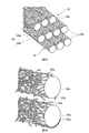
- 4A and 4B are schematic views for explaining a composite carbon fiber bundle constituting a reinforcing layer.
- FIG. 4A is an overall view
- FIG. 4B is an enlarged view.
- It is a schematic diagram explaining the joining state of carbon fibers in the interface of a composite carbon fiber bundle.
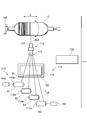
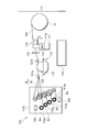
- It is a model top view of a filament winding apparatus. It is a model side view of the filament winding apparatus shown in FIG. FIG.
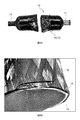
- FIG. 8A is a photograph showing a high-pressure vessel cut to observe a cross section of a reinforcing layer after an internal pressure fracture test
- FIG. 8A is an overall image
- FIG. 8B is an enlarged image of a cut portion.
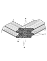
- It is a mimetic diagram showing a plurality of laminated composite carbon fiber bundles contained in a section of a reinforcing layer.
- FIG. 10A is a micrograph showing a cross section of a reinforcing layer sample
- FIG. 10A is an overall image
- FIG. 10B is an enlarged image of a region Y1 in FIG. 10A
- 10B is a scanning electron microscope (SEM) image of the region Y2 in FIG. 10B
- FIG. 11A is an overall image
- FIG. 11B is an enlarged image.
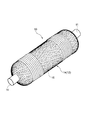
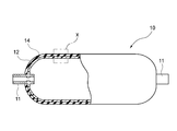
- the high-pressure vessel 10 of this embodiment includes a hermetically sealed hollow vessel 12 and a reinforcing layer 14 that covers the outer surface of the hollow vessel 12.
- the hollow container 12 has a substantially cylindrical cylindrical portion and convex spherical portions provided at both ends of the cylindrical portion.
- the convex spherical portions at both ends are constituted by isotonic curved surfaces.
- a metal base 11 for connecting the high-pressure vessel 10 to an external pipe or the like (not shown) is provided at each vertex of the convex spherical portion.
- a resin container mainly composed of nylon is used as the hollow container 12.
- the base 11 of the hollow container 12 is made of aluminum.
- a space between the hollow container 12 and the base 11 is sealed with a rubber gasket (not shown).
- the reinforcing layer 14 includes a composite carbon fiber bundle 16 wound around the outer surface of the hollow container 12.
- the composite carbon fiber bundles 16 are wound around the outer surface of the hollow container 12 so that the longitudinal directions of the composite carbon fiber bundles 16 are different from each other.
- the composite carbon fiber bundle 16 is formed on the outside of the hollow container 12 by helical winding wound in an oblique direction with respect to the cylindrical portion of the hollow container 12 and hoop winding wound in a direction perpendicular to the axis of the cylindrical portion of the hollow container 12. It is wrapped around the surface.
- the reinforcing layer 14 is composed of a composite carbon fiber bundle 16 laminated in a plurality of layers via the interface 17.
- the reinforcing layer 14 includes a composite carbon fiber bundle 16 in which seven layers are laminated.
- the plurality of laminated composite carbon fiber bundles 16 are fixed by a cured product of a thermosetting resin (not shown).
- stacked several composite carbon fiber bundle 16 is being fixed by the hardened
- the composite carbon fiber bundle 16 may be used as a secondary fiber bundle obtained by bundling a plurality of bundles (for example, four bundles).
- Each of the plurality of composite carbon fiber bundles 16 includes a plurality of continuous composite carbon fibers 18 as shown in FIG. 4A.
- the plurality of composite carbon fibers 18 included in each composite carbon fiber bundle 16 is also thermoset. Are fixed to each other by a cured resin.
- the composite carbon fiber 18 includes a continuous carbon fiber 18a and a plurality of CNTs 20a attached to the surface of the carbon fiber 18a. As shown in FIG.
- the CNT 20a is basically in close contact with the surface of the carbon fiber 18a, but the CNT 20a partially floating from the surface of the carbon fiber 18a and adhering to the surface of the carbon fiber 18a is also included. Exists. In FIG. 4B, the distance between the carbon fibers 18a is exaggerated for easy understanding of the state of the CNT 20a. The carbon fiber 18a to which the CNT 20a is attached will be described in detail later.
- the composite carbon fiber bundle 16 In the composite carbon fiber bundle 16, ten continuous composite carbon fibers 18 are shown for explanation, but the composite carbon fiber bundle 16 in this embodiment has 10,000 to 30,000 continuous composite carbon fibers 18. It is constituted by. The plurality of continuous composite carbon fibers 18 are arranged in one direction while substantially maintaining the linearity without being entangled with each other to constitute the composite carbon fiber bundle 16.
- the entanglement of the composite carbon fiber 18 in the composite carbon fiber bundle 16 can be evaluated by the degree of disturbance of the composite carbon fiber 18.
- the composite carbon fiber bundle 16 is observed at a constant magnification by SEM, and the length of a predetermined number (for example, 10) of composite carbon fibers 18 included therein is measured.
- the degree of disturbance of the composite carbon fiber 18 can be evaluated based on the length variation, the difference between the maximum value and the minimum value, and the standard deviation of the predetermined number of composite carbon fibers 18.
- the fact that the plurality of composite carbon fibers 18 are not substantially entangled can also be determined by measuring the entanglement degree according to the entanglement degree measuring method of JIS L1013: 2010 “Chemical fiber filament yarn test method”, for example. .
- the measured degree of entanglement is small, it means that there is little entanglement between the composite carbon fibers 18 in the composite carbon fiber bundle 16.
- the plurality of composite carbon fibers 18 are not substantially entangled, so that each of the composite carbon fibers 18 can contribute to the strength.
- each of the plurality of continuous composite carbon fibers 18 includes a continuous carbon fiber 18a and a plurality of CNTs 20a attached to the surface of the carbon fiber 18a.
- the carbon fiber 18a is a fiber having a diameter of 5 to 20 ⁇ m.
- the carbon fiber 18a is obtained by firing organic fibers derived from petroleum such as polyacrylonitrile, rayon and pitch, coal and coal tar, and organic fibers derived from wood and plant fibers.
- the CNT 20a is directly attached to the surface of the carbon fiber 18a.
- adheresion refers to bonding by van der Waals force.
- the plurality of CNTs 20a attached to the surface of the carbon fiber 18a are evenly dispersed and intertwined over almost the entire surface of the carbon fiber 18a.
- the plurality of CNTs 20a can form a structure 20 having a network structure on the surface of the carbon fiber 18a by being in direct contact with or directly connected to each other. It is preferable that there is no inclusion such as a dispersant such as a surfactant or an adhesive between the CNTs 20a.
- connection includes physical connection (simple contact).
- direct contact or direct connection includes not only a state in which a plurality of CNTs are simply in contact but also a state in which a plurality of CNTs are integrally connected, and is limitedly interpreted. Should not be done.
- the length of the CNT 20a is preferably 0.1 to 50 ⁇ m.
- the length of the CNT 20a is 0.1 ⁇ m or more, the CNTs 20a are entangled and directly connected. Further, when the length of the CNT 20a is 50 ⁇ m or less, it becomes easy to disperse evenly. On the other hand, if the length of the CNT 20a is less than 0.1 ⁇ m, the CNTs 20a are less likely to be entangled with each other. Further, the CNT 20a tends to aggregate when the length exceeds 50 ⁇ m.
- the CNT 20a preferably has an average diameter of about 30 nm or less.
- the diameter of the CNT 20a is 30 nm or less, the CNT 20a is rich in flexibility, and a network structure can be favorably formed on the surface of each carbon fiber 18a.
- the diameter of the CNT 20a exceeds 30 nm, the flexibility is lost, and it becomes difficult to form a network structure on the surface of each carbon fiber 18a.
- the diameter of CNT20a be the average diameter measured using the transmission electron microscope (TEM: Transmission
- the plurality of CNTs 20a are uniformly attached to the respective surfaces of the plurality of continuous carbon fibers 18a.
- the attached state of the CNT 20a on the surface of the carbon fiber 18a can be observed by SEM, and the obtained image can be visually evaluated.
- a plurality of CNTs 20a are uniformly attached to the surface of a plurality of continuous carbon fibers 18a. Therefore, the carbon fiber having the CNT aggregate attached to the surface is not substantially contained in the composite carbon fiber bundle 16. Carbon fibers with insufficient amount of CNT adhering to the surface are not substantially present in the composite carbon fiber bundle 16.
- the CNT 20a is directly attached to the surface of the carbon fiber 18a. That is, the CNT 20a is directly attached to the surface of the carbon fiber 18a without any dispersant or adhesive such as a surfactant interposed between the surface of the carbon fiber 18a.
- each of the plurality of continuous carbon fibers 18a included in the composite carbon fiber bundle 16 is connected to the other through a cured product of a thermosetting resin (not shown) and the plurality of CNTs 20a. It is in contact with the carbon fiber 18a.
- a cured product of a thermosetting resin including a plurality of CNTs 20a attached to the carbon fiber 18a is referred to as a stress relaxation part.
- FIG. 5 schematically showing the interface 17 between the composite carbon fiber bundles 16 shows the carbon fibers 18 a that are in contact with each other via the stress relaxation portion 26.
- a stress relaxation portion 26 including a cured product 22 of a thermosetting resin.
- the stress relaxation part 26 includes a plurality of CNTs 20a. A part of the plurality of CNTs 20a is directly attached to the surface of each carbon fiber 18a as described above. A part of one CNT 20a may adhere to the surface of the carbon fiber 18a.
- the high-pressure vessel 10 can be manufactured by winding the composite carbon fiber bundle 16 impregnated with the thermosetting resin around the outer surface of the airtight hollow vessel 12 and curing the thermosetting resin. Impregnation means that a thermosetting resin is infiltrated into the gaps between the composite carbon fiber bundles 16.
- the composite carbon fiber bundle 16 is obtained by immersing a carbon fiber bundle including a plurality of continuous carbon fibers 18a in a CNT isolation dispersion liquid (hereinafter also simply referred to as a dispersion liquid) in which the CNTs 20a are isolated and dispersed, and having a predetermined frequency.
- the structure 20 can be manufactured by applying ultrasonic vibrations to attach the CNTs 20a to the respective surfaces of the carbon fibers 18a.
- CNT 20a produced as follows can be used.
- the CNT 20a is formed by forming a catalyst film made of aluminum and iron on a silicon substrate by using a thermal CVD method as described in, for example, Japanese Patent Application Laid-Open No. 2007-12611, and fine particles of catalyst metal for CNT growth. And can be produced by bringing a hydrocarbon gas into contact with the catalytic metal in a heated atmosphere.
- CNT obtained by other manufacturing methods such as an arc discharge method and a laser evaporation method, it is preferable to use a material containing as little impurities as possible.
- the CNT produced in this production example is a long CNT linearly oriented with a high aspect ratio of a diameter of 30 nm or less and a length of several hundred ⁇ m to several mm.
- the CNT may be a single layer or a multilayer, but is preferably a multilayer CNT.
- Isolated dispersion refers to a state where the CNTs 20a are dispersed in a dispersion medium in a state where the CNTs 20a are physically separated and not entangled one by one.
- the isolated dispersion means a state where the ratio of an aggregate in which two or more CNTs 20a are gathered in a bundle is 10% or less.
- the CNT 20a produced as described above is added to a dispersion medium, and the dispersion of the CNT 20a is made uniform by a homogenizer, shear, an ultrasonic disperser, or the like.
- the dispersion medium include alcohols such as water, ethanol, methanol, and isopropyl alcohol, and organic solvents such as toluene, acetone, tetrahydrofuran (THF), methyl ethyl ketone (MEK), hexane, normal hexane, ethyl ether, xylene, methyl acetate, and ethyl acetate.
- a solvent can be used.
- additives such as a dispersant and a surfactant are not necessarily required, but such additives may be used as long as the functions of the carbon fiber 18a and the CNT 20a are not limited.
- the frequency of the ultrasonic waves is preferably 100 kHz or more, and more preferably 130 kHz or more.
- a carbon fiber bundle containing a plurality of continuous carbon fibers 18a is immersed in the dispersion in the reversible reaction state. Then, a reversible reaction state between the dispersed state and the aggregated state of the CNT 20a occurs also on the surface of each carbon fiber 18a, and the CNT 20a adheres to the surface of each carbon fiber 18a when shifting from the dispersed state to the aggregated state.
- the composite carbon fiber bundle 16 is substantially free from entanglement between the carbon fibers 18a. On each surface of the carbon fiber 18a in the composite carbon fiber bundle 16, the CNTs 20a are well attached to form the structure 20.
- the plurality of composite carbon fibers 18 are not substantially entangled, even when the composite carbon fiber bundle 16 is impregnated with a thermosetting resin, there is a possibility that the strength may decrease due to the entanglement between the carbon fibers 18a. Very small. Since the structure 20 is formed by the good adhesion of the CNTs 20a to the surface of each carbon fiber 18a, the carbon fiber 18a is firmly bonded to each other by exerting strength by curing the thermosetting resin. Can do.
- the reinforcing layer 14 can be formed on the outer surface of the hollow container 12 by the filament winding method (hereinafter referred to as “FW method”) using the composite carbon fiber bundle 16 produced as described above.
- FW method the filament winding method
- a filament winding apparatus hereinafter referred to as “FW apparatus” 111 shown in FIGS. 6 and 7 can be used.
- the FW device 111 includes a composite carbon fiber bundle supply unit (composite fiber bundle supply means) 112, a resin impregnation device 113, a composite carbon fiber bundle guide 114, and a yarn feeding unit 115. Since the FW device 111 includes the resin impregnation device 113 for impregnating the composite carbon fiber bundle 16 with a molten resin, it is a wet method device.
- the chuck 109 can rotatably support the sealable hollow container 12.
- the yarn supplying unit 115 provided in the attachment portion 122 can reciprocate along the longitudinal direction of the hollow container 12 (the direction of arrow A in FIG. 6).
- the yarn feeding unit 115 is attached to the second actuator 118 supported by the first actuator 117.
- the second actuator 118 is supported by the first actuator 117 via the moving body 117a.
- the first actuator 117 has a known configuration that uses a ball screw (not shown) and moves a moving body 117a that can move integrally with a nut (not shown) in one axial direction.
- the yarn supplying unit 115 can reciprocate in the direction orthogonal to the paper surface (the direction of arrow A in FIG. 6) by the action of the first actuator 117.
- the yarn supplying unit 115 is a second member on the moving body 117a.
- the actuator 118 can be moved up and down in the direction of arrow C in FIG.
- the illustrated FW device 111 includes four bobbins B1 to B4 around which the composite carbon fiber bundle 16 is wound in the composite carbon fiber bundle supply unit 112.
- Each of the bobbins B1 to B4 is supported by a support shaft 112a connected to the creel stand 112b.
- a powder brake or a so-called permanent torque configured to apply a load to the support shaft 112a by eddy current can be used.
- the resin impregnation apparatus 113 includes a resin tank 119 that contains a molten thermosetting resin, and an impregnation roller 120 that is immersed in the thermosetting resin in the resin tank 119.
- the impregnation roller 120 rotates in the molten thermosetting resin, and supplies the molten thermosetting resin to the composite carbon fiber bundle 16.
- feed rolls 121a and 121b are arranged above the resin tank 119.
- the feed roll 121a feeds the composite carbon fiber bundle 16 drawn in the direction of arrow B from the bobbins B1 to B4 and guides it to a predetermined position in the resin tank 119. Between the composite carbon fiber bundle supply unit 112 and the feed roll 121a, tension rollers (not shown) are provided corresponding to the composite carbon fiber bundles 16 drawn from the bobbins B1 to B4.
- the composite carbon fiber bundle 16 guided to the feed roll 121a is pressed against the surface of the impregnation roller 120. Since the molten thermosetting resin adheres to the surface of the impregnation roller 120, the composite carbon fiber bundle 16 passes through the resin impregnation device 113, so that the composite carbon fiber bundle 16 has a molten thermosetting resin. Is impregnated.
- the feed roll 121b guides the composite carbon fiber bundle 16 after being impregnated with the molten thermosetting resin by the resin impregnation apparatus 113 to the composite carbon fiber bundle guide 114.
- the composite carbon fiber bundle guide 114 guides the plurality of composite carbon fiber bundles 16 impregnated with a molten thermosetting resin to the yarn supplying unit 115.
- the yarn feeding unit 115 bundles a plurality of composite carbon fiber bundles 16 guided from the composite carbon fiber bundle guide 114 in a row and supplies the bundle to the hollow container 12 as a secondary fiber bundle 16X.
- the chuck 109 supports the hollow container 12 rotatably about the axis of the hollow container 12.
- the chuck 109 that supports the hollow container 12 is rotationally driven by a variable speed motor (not shown).
- the variable speed motor is controlled by a control unit (abnormality determination unit) 130.
- the chuck 109 is rotationally driven in synchronization with the moving speed of the yarn feeding unit 115. Accordingly, the composite carbon fiber bundle 16 can be wound around the hollow container 12 while setting the winding angle of the secondary fiber bundle 16X around the hollow container 12 to an arbitrary angle.
- Rotational speed detectors (speed detecting means) 150 for detecting the rotational speeds of the bobbins B1 and B4 are provided on the bobbins B1 and B4 located at both ends in plan view.
- the rotation speed detector 150 is provided on the support shaft 112a of each of the bobbins B1 and B4, and sequentially detects the rotation speed of the bobbins B1 and B4.
- the detection output of the rotation speed detector 150 is given to the control unit 130.
- the rotation speed detector 150 is provided on the bobbins B1 and B4 that supply the composite carbon fiber bundles 16 positioned at both ends in the width direction of the composite carbon fiber bundle 16, respectively.
- the rotation speed detector 150 may be provided in all the bobbins B1 to B4.
- the yarn feeding unit 115 is fixed to the second actuator 118 at the attachment portion 122 and attached to the FW device 111.
- the hollow container 12 is first supported by the chuck 109 of the FW device 111.
- the yarn feeding unit 115 is moved to the original position. Arrange at (winding start position).
- the position of the yarn feeding unit 115 in the longitudinal direction of the hollow container 12 can be adjusted by operating the first actuator 117.
- the position of the yarn feeding unit 115 in the diameter direction of the hollow container 12 can be adjusted by operating the second actuator 118.
- the plurality of composite carbon fiber bundles 16 are fed out in the direction of arrow B from the composite carbon fiber bundle supply unit 112 and guided to the yarn supplying unit 115 through the resin impregnation device 113 and the fiber bundle guide 114.
- the composite carbon fiber bundles 16 impregnated with the thermosetting resin are bundled in a line to form a secondary fiber bundle 16X.
- the end of the secondary fiber bundle 16X is fixed at a predetermined position of the hollow container 12.
- the end of the secondary fiber bundle 16X can be manually fixed by an operator using, for example, an adhesive tape.
- the winding conditions such as the length, diameter, and rotation speed of the hollow container 12 and the width when the secondary fiber bundle 16X is wound around the hollow container 12 are input to the control unit 130.
- the winding operation of the secondary fiber bundle 16X by the FW device 111 is started.
- the hollow container 12 is rotated in a certain direction.
- the first actuator 117 in the yarn supplying unit 115 is driven.
- the yarn feeding unit 115 can move in parallel with the longitudinal direction of the hollow container 12 from the winding start position together with the moving body 117a.
- the plurality of composite carbon fiber bundles 16 are sequentially pulled out from the composite carbon fiber bundle supply unit 112.
- the plurality of composite carbon fiber bundles 16 are impregnated with a molten thermosetting resin in the resin impregnation apparatus 113. Thereafter, the plurality of composite carbon fiber bundles 16 impregnated with the thermosetting resin are bundled in a row by the yarn feeding unit 115 and wound around the wound surface of the hollow container 12 while applying a tensile load as the secondary fiber bundle 16X. .
- the magnitude of the tensile load can be appropriately set in consideration of the winding conditions.
- the secondary fiber bundle 16X can be wound around the outer surface of the hollow container 12 by an arbitrary winding method so as to be a layer having an arbitrary thickness.
- the winding method of the secondary fiber bundle 16X and the thickness of the layer after winding can be set by adjusting the moving speed of the moving body 117a and the rotating speed of the hollow container 12.
- the winding method of the secondary fiber bundle 16X can be selected from helical winding and hoop winding, for example.
- the hollow container 12 is removed from the chuck 109, placed in a heating furnace, and heated at a predetermined temperature.
- the thermosetting resin By curing the thermosetting resin, the composite carbon fiber bundle 16 wound around the outer surface of the hollow container 12 is fixed and the reinforcing layer 14 is formed.
- the high-pressure vessel 10 of the present embodiment in which the outer surface of the hollow vessel 12 is covered with the reinforcing layer 14 is obtained.
- the reinforcing layer 14 is formed by a wound composite carbon fiber bundle 16.
- the high-pressure vessel 10 is reinforced by a reinforcing layer 14 including a composite carbon fiber bundle 16 that is wound around the outer surface of a hollow vessel 12 and fixed with a cured product 22 of a thermosetting resin.
- the composite carbon fiber bundle 16 includes a plurality of carbon fibers 18a having a plurality of CNTs 20a attached to the surface.
- the carbon fibers 18a are in contact with each other via a cured product 22 of a thermosetting resin in which CNTs 20a are dispersed, that is, a stress relaxation portion 26.
- the stress relaxation part 26 is also present between the carbon fibers 18 a included in one composite carbon fiber bundle 16 and the carbon fibers 18 a included in the other composite carbon fiber bundle 16.
- the elastic modulus of carbon fiber is higher than the elastic modulus of the cured product of thermosetting resin, so stress concentration occurs at the interface between the carbon fiber and the cured product of thermosetting resin due to the difference in elastic modulus. To do.
- the load at this time is preferentially borne by the carbon fiber.
- a stress relaxation portion 26 in which the CNT 20a is combined with the cured product 22 of the thermosetting resin is formed between the carbon fibers 18a.
- the elastic modulus of the stress relaxation part 26 becomes higher than the elastic modulus of the cured product 22 of the thermosetting resin. Even if the elastic modulus of the carbon fiber 18a is different from that of the cured product 22 of the thermosetting resin, the stress relaxation portion 26 is interposed, so that a rapid elastic modulus change is suppressed and the stress concentration is relaxed.
- the toughness of the composite carbon fiber bundle 16 can be improved, and the pressure strength can be increased.
- the adhesive force between the carbon fibers 18a and the cured product 22 of the thermosetting resin is reinforced by the anchor effect.
- the peel strength at the interface between the carbon fiber 18a and the cured product 22 of the thermosetting resin is improved.
- the presence of the CNT 20a between the carbon fiber 18a and the cured product 22 of the thermosetting resin allows the carbon fibers 18a and the composite carbon fiber bundles 16 to be firmly bonded to each other.
- the stress relaxation portion 26 exists between the carbon fibers 18 a included in one composite carbon fiber bundle 16 and the carbon fibers 18 a included in the other composite carbon fiber bundle 16.
- the composite carbon fiber bundle 16 is wound around the outer surface of the hollow container 12 while applying a tensile load. Therefore, the carbon fibers 18a constituting the composite carbon fiber bundle 16 are oriented in a certain direction. To do. By applying a tensile load to the composite carbon fiber bundle 16, excessive thermosetting resin between the carbon fibers 18a is extruded. By increasing the uniformity of the carbon fibers 18a in the composite carbon fiber bundle 16, the variation in the content (Vf) of the composite carbon fiber bundle 16 in the reinforcing layer 14 is reduced, and the uniformity of the composite carbon fiber bundle 16 is also increased. It is done.
- the composite carbon fibers 18 can be in contact with each other directly or through a cured product 22 of a thermosetting resin containing a high concentration of CNTs 20a.
- a thermosetting resin containing a high concentration of CNTs 20a By increasing the density of the CNTs 20a, the CNTs 20a can be more strongly coupled by being closer to each other.
- the effect of the stress relaxation part 26 is further enhanced.
- the variation in strength can be reduced due to the high uniformity of the composite carbon fiber bundle 16. Wrapping the composite carbon fiber bundle 16 around the outer surface of the hollow container 12 while applying a tensile load also improves the pressure strength.
- the present invention is not limited to the above-described embodiment, and can be appropriately changed within the scope of the gist of the present invention.
- the composite carbon fiber bundle 16 for forming the reinforcing layer 14 can be produced using a so-called regular toe composed of 10,000 to 30,000 composite carbon fibers 18.
- the diameter of the carbon fiber 18a constituting the composite carbon fiber bundle 16 can be appropriately set within a range of 5 to 10 ⁇ m.
- the dispersion medium may be evaporated from the composite carbon fiber bundle by using an evaporator in addition to placing on the hot plate.
- the hollow container 12 in which the reinforcing layer 14 is formed on the outer surface may be formed of other materials as long as it can accommodate and seal a gas inside. As long as it has airtightness, as the hollow container 12, a container made of other metals or resins can be used.
- the composite carbon fiber bundle 16 When the composite carbon fiber bundle 16 is wound around the outer surface of the hollow container 12, the composite carbon fiber bundle 16 can be laminated in an arbitrary number of layers so as to have a desired layer thickness.
- the reinforcing layer 14 can also be formed by a dry method.
- a prepreg in which a composite carbon fiber bundle 16 is impregnated with a thermosetting resin is used.
- the thermosetting resin impregnated in the tuplepreg may be in a semi-cured state by drying or heating.
- the tuprepreg is wound around the outer surface of the hollow container 12 while applying a tensile load.
- the thermosetting resin can be melted and the tuplepreg can be wound around the outer surface of the hollow container 12.
- the thermosetting resin may be heated and melted and cured in a subsequent process.
- thermosetting resin for fixing the composite carbon fiber bundle 16 a polyester resin, a polyamide resin, or the like may be used in addition to the epoxy resin.
- the hollow container 12 in which the composite carbon fiber bundle 16 impregnated with the thermosetting resin is wound around the outer surface is disposed in the induction heating device, and the thermosetting resin is cured by induction heating. It can also be made.
- a composite carbon fiber bundle 16 used for manufacturing the high-pressure container of the example was manufactured by the procedure shown in the above manufacturing method.
- the CNT 20a MW-CNT (Multi-walled Carbon Nanotubes) grown on a silicon substrate to a diameter of 10 to 15 nm and a length of 100 ⁇ m or more by a thermal CVD method was used.
- a 3: 1 mixed acid of sulfuric acid and nitric acid was used, followed by filtration and drying after washing.
- the CNT 20a was cut with an ultrasonic homogenizer in a dispersion medium until the length became 0.5 to 10 ⁇ m.
- the dispersion was prepared using MEK as the CNT dispersion medium.
- the CNT concentration in the dispersion was 0.01 wt%. This dispersion does not contain a dispersant or an adhesive.
- T700SC-12000 manufactured by Toray Industries, Inc.
- the carbon fiber bundle used here includes 12,000 carbon fibers 18a.
- the carbon fiber 18a has a diameter of about 7 ⁇ m and a length of about 100 m.
- the carbon fiber bundle was held in the dispersion for 10 seconds.
- the carbon fiber bundle was taken out of the dispersion and dried on a hot plate at about 80 ° C., and a plurality of CNTs 20a were adhered to the surfaces of the carbon fibers 18a constituting the carbon fiber bundle. As a result of microscopic observation, it was confirmed that the plurality of CNTs 20a formed a structure 20 having a network structure. Thus, a composite carbon fiber bundle 16 used for forming the reinforcing layer 14 was obtained.
- the composite carbon fiber bundle 16 produced as described above was wound around the outer surface of the hollow container 12 by the FW method to form the reinforcing layer 14.
- an aluminum liner (outer diameter 60 mm, length 250 mm) was prepared.
- the composite carbon fiber bundle 16 was wound around the outer surface of the hollow container 12 by impregnating a molten thermosetting resin by a wet method as described with reference to FIGS.
- a molten thermosetting resin As the thermosetting resin, a bisphenol epoxy resin (Mitsubishi Chemical Corporation: JER828) was used. The condition of the FW device was selected, and the composite carbon fiber bundle 16 was wound around the outer surface of the hollow container 12 so that the content of the composite carbon fiber bundle 16 in the reinforcing layer 14 was 60%.
- the composite carbon fiber bundle 16 impregnated with the bisphenol-based epoxy resin was wound around the outer surface of the hollow container 12 while applying a tensile load so as to have a predetermined layer thickness.
- a combination of helical winding and hoop winding was used for winding the composite carbon fiber bundle 16.
- the composite carbon fiber bundle 16 includes a helical winding with a layer thickness of 0.49 mm, a hoop winding with a layer thickness of 0.49 mm, a helical winding with a layer thickness of 0.49 mm, and a double-end hoop winding with a layer thickness of 0.25 mm.
- the hollow container 12 in which the composite carbon fiber bundle 16 is wound on the outer surface is placed in a curing furnace and heated at 100 ° C. for 1.5 hours and then at 160 ° C. for 4 hours to cure and strengthen the bisphenol epoxy resin.
- the layer 14 was formed, and the high-pressure vessel 10 of the example was produced.
- a high pressure vessel of a comparative example was produced in the same manner except that the reinforcing layer was formed by using the above-mentioned T700SC-12000 (manufactured by Toray Industries, Inc.) as it was in an uncomposited state where CNTs were not attached.
- one base of the high-pressure vessel was sealed, and water as a pressure medium was accommodated inside the high-pressure vessel.
- the other base is connected to a pump by high-pressure piping, and pressure is applied in the high-pressure vessel.
- a strain gauge (2 sheets / body) was affixed to the surface of the high-pressure vessel, and a destructive test was conducted while increasing the internal pressure while observing the state of strain.
- the occurrence of cracks in the hollow container can be confirmed from the measurement result of strain by the strain gauge.
- the pressure at the time of cracking is the burst pressure of the high-pressure vessel. Since the burst pressure reflects the pressure strength, the larger the burst pressure, the better.
- the burst pressure of the high pressure vessel of the comparative example was 59.5 MPa, whereas the burst pressure of the high pressure vessel of the example was 67.3 MPa.
- the reinforcing layer covering the outer surface of the hollow container is formed using a composite carbon fiber bundle including carbon fibers having CNTs attached to the surface. It can be seen that the pressure-resistant strength of the high-pressure vessel is improved by about 13% because the reinforcing layer is reinforced with CNTs.
- the cross section of the reinforcing layer 14 was observed for the high-pressure vessel 10 of the example after the internal pressure fracture test.
- the high-pressure vessel 10 after the internal pressure fracture test was cut along the diameter of the cylindrical portion as shown in FIG. 8A.
- the reinforcing layer 14 is formed by winding the composite carbon fiber bundle 16 around the outer surface of the hollow container 12. In the vicinity of the cut portion of the high-pressure vessel 10, a crack 30 is generated in a part of the hollow vessel 12 as shown in FIG. 8B.
- a section of the reinforcing layer 14 includes a plurality of composite carbon fiber bundles 16 stacked via an interface 17.
- Each composite carbon fiber bundle 16 includes a plurality of carbon fibers 18a.
- the two composite carbon fiber bundles 16 that are in contact with each other at the interface 17 extend with different directions as longitudinal directions.
- the sections were fixed with an epoxy adhesive in order to prevent the plurality of laminated composite carbon fiber bundles 16 from being loosened. Furthermore, the surface where the laminated state of the composite carbon fiber bundle 16 appears was polished and sandwiched between transparent films to prepare a reinforcing layer sample for microscopic observation.
- Fig. 10 shows a micrograph of the reinforcing layer sample.
- the reinforcing layer sample includes a plurality of composite carbon fiber bundles 16 stacked via an interface 17.
- FIG. 10B shows an enlarged image of the region Y1 in FIG. 10A.
- the composite carbon fiber bundles 16 are laminated via the interface 17.
- Each composite carbon fiber bundle 16 includes a plurality of carbon fibers 18a fixed with a cured product 22 of a thermosetting resin.
- the carbon fibers 18a in each composite carbon fiber bundle 16 are in contact with each other at the interface 17.
- FIG. 11A and 11B show SEM images of the region Y2 in FIG. 10B. From these figures, it was confirmed that the carbon fibers 18a having a plurality of CNTs 20a attached to the surface are in contact with each other via a cured product 22 of a thermosetting resin. Further, it was confirmed that the cured product 22 of the thermosetting resin existing between the carbon fibers 18a contained a plurality of CNTs 20a. A cured product 22 of a thermosetting resin including a plurality of CNTs 20a constitutes a stress relaxation portion 26.
- the high-pressure vessel 10 of the example was able to increase the pressure strength.
- CFRP test piece ⁇ Comparison with CFRP test piece>
- the composite carbon fiber bundle 16 used in the high-pressure vessel 10 of the example and the uncomposite carbon fiber bundle used in the high-pressure vessel of the comparative example were subjected to tensile evaluation using a CFRP test piece.
- a CFRP test piece (width of about 15 mm, parallel part length of about 150 mm, thickness of about 0.8 mm) was prepared without applying a tensile load.
- the composite carbon fiber bundle 16 was impregnated with the same bisphenol-based epoxy resin as described above, and was cured under the same conditions as described above to produce a test piece a.
- the test piece b was produced by the same method using the uncombined carbon fiber bundle.
- the tensile strength of the test piece a and the test piece b was measured with a tensile tester. Although the tensile strength of the test piece a was larger than the tensile strength of the test piece b, the difference was about 6%. Compared to the difference in pressure strength (13%) of the high-pressure containers of the above-described Examples and Comparative Examples, the difference in tensile strength between CFRP test pieces is small.
- the composite carbon fiber bundle 16 By winding the composite carbon fiber bundle 16 around the outer surface of the hollow container 12 while applying a tensile load, in addition to the carbon fibers 18a being oriented in a certain direction, the density of the CNTs 20a between the carbon fibers 18a is increased. From this, it is presumed that the effect of the composite carbon fiber bundle 16 is sufficiently developed.
Landscapes
- Engineering & Computer Science (AREA)
- Mechanical Engineering (AREA)
- Chemical & Material Sciences (AREA)
- Composite Materials (AREA)
- General Engineering & Computer Science (AREA)
- Filling Or Discharging Of Gas Storage Vessels (AREA)
- Moulding By Coating Moulds (AREA)
- Textile Engineering (AREA)
Abstract
密閉可能な中空容器(12)と、前記中空容器(12)の外表面を覆う補強層(14)とを備えた高圧容器(10)であって、前記補強層(14)は、前記中空容器(12)の外表面に巻き付けられて熱硬化性樹脂の硬化物により固定され、複数層積層された複合炭素繊維束(16)を備え、一方の複合炭素繊維束(16)に含まれる炭素繊維(18a)と、他方の複合炭素繊維束(16)に含まれる炭素繊維の間に、前記熱硬化性樹脂の硬化物(22)と複数のカーボンナノチューブ(20a)とを含む応力緩和部(26)が設けられていることを特徴とする、より高い耐圧強度を有する高圧容器、およびかかる高圧容器の製造方法を提供する。
Description
本発明は、高圧容器および高圧容器の製造方法に関する。
近年、燃料ガスの燃焼エネルギーや、燃料ガスの電気化学反応により生成される電気エネルギーによって駆動する車両が開発されている。水素ガスや天然ガス等の燃料ガスは、密閉可能な中空容器(ライナー)を備えた高圧容器内に、常圧より高い圧力で貯蔵される。中空容器の外表面は、樹脂を含浸した繊維を巻き付けて形成された補強層(繊維強化樹脂層)で被覆されている(例えば、特許文献1、2)。
高圧容器に充填される燃料ガスの圧力(充填圧)が高いほど充填量が増え、車両の走行可能距離を長くできるので、燃料ガスの充填圧は高いほうが好ましい。そして、燃料ガスの充填圧をより高めるためには、高圧容器は、より高い耐圧強度を有することが要求される。
高圧容器の耐圧強度を高めるためには、例えば補強層に含まれる繊維の量を多くする必要がある。繊維の量の増加は、高圧容器の製造コスト、質量、体格の増大といった問題を引き起こす。そのため、補強層を形成する繊維の量を増やすことなく、高圧容器の耐圧強度を高めることが望まれる。
そこで本発明は、より高い耐圧強度を有する高圧容器、およびかかる高圧容器の製造方法を提供することを目的とする。
本発明に係る高圧容器は、密閉可能な中空容器と、前記中空容器の外表面を覆う補強層とを備えた高圧容器であって、前記補強層は、前記中空容器の外表面に巻き付けられて熱硬化性樹脂の硬化物により固定され、複数層積層された複合炭素繊維束を備え、一方の複合炭素繊維束に含まれる炭素繊維と、他方の複合炭素繊維束に含まれる炭素繊維の間に、前記熱硬化性樹脂の硬化物と複数のカーボンナノチューブとを含む応力緩和部が設けられていることを特徴とする。
本発明に係る高圧容器の製造方法は、密閉可能な中空容器の外表面に補強層を有する高圧容器の製造方法であって、前記中空容器の外表面に、熱硬化性樹脂が含浸された複合炭素繊維束を引張り荷重を掛けながら巻き付ける工程と、前記熱硬化性樹脂を硬化させて前記補強層を形成する工程とを含み、前記複合炭素繊維束は、複数のカーボンナノチューブを含む構造体が表面に形成された複数の連続した炭素繊維を含み、前記構造体は、前記複数の連続した炭素繊維のそれぞれの表面に直接付着していることを特徴とする。
本発明によれば、高圧容器は、熱硬化性樹脂の硬化物で固定された複数層の複合炭素繊維束を含む補強層を備えている。一方の複合炭素繊維束に含まれる炭素繊維と、他方の複合炭素繊維束に含まれる炭素繊維の間に、熱硬化性樹脂の硬化物を含む応力緩和部が形成されているので靱性が向上する。その結果、強度の高い補強層が形成され、より高い耐圧強度を有する高圧容器が得られる。
本発明の高圧容器の製造方法において補強層の製造に用いられるのは、複数のカーボンナノチューブ(以下、CNTと称する)が表面に付着した複数の連続した炭素繊維を含む複合炭素繊維束である。複合炭素繊維束に熱硬化性樹脂を含浸させ、引張り荷重を掛けながら中空容器の外表面に巻き付けることによって、複合炭素繊維束同士の間に応力緩和部が形成されるので、強度の高い補強層が得られる。こうして、耐圧強度のより高い高圧容器を製造することができる。
以下、図面を参照して本発明の実施形態について詳細に説明する。
1.全体構成
図1,2に示すように、本実施形態の高圧容器10は、密閉可能な中空容器12と、中空容器12の外表面を覆う補強層14とを備えている。本実施形態の場合、中空容器12は、略円筒形状の円筒部と、円筒部両端に設けられた凸状球面部とを有する。両端の凸状球面部は、等張力曲面によって構成されている。凸状球面部の各頂点には、高圧容器10を外部配管等(図示せず)と接続するための金属製の口金11が、それぞれ設けられている。本実施形態では、中空容器12としては、ナイロンを主成分とする樹脂製容器を用いる。中空容器12の口金11はアルミニウム製である。中空容器12と口金11の間は、図示しないゴム製のガスケットにより密閉されている。
図1,2に示すように、本実施形態の高圧容器10は、密閉可能な中空容器12と、中空容器12の外表面を覆う補強層14とを備えている。本実施形態の場合、中空容器12は、略円筒形状の円筒部と、円筒部両端に設けられた凸状球面部とを有する。両端の凸状球面部は、等張力曲面によって構成されている。凸状球面部の各頂点には、高圧容器10を外部配管等(図示せず)と接続するための金属製の口金11が、それぞれ設けられている。本実施形態では、中空容器12としては、ナイロンを主成分とする樹脂製容器を用いる。中空容器12の口金11はアルミニウム製である。中空容器12と口金11の間は、図示しないゴム製のガスケットにより密閉されている。
補強層14は、中空容器12の外表面に巻き付けられた複合炭素繊維束16を備えている。複合炭素繊維束16同士は、複合炭素繊維束16の長手方向がそれぞれ異なる方向となるように、中空容器12の外表面に巻き付けられている。複合炭素繊維束16は、中空容器12の円筒部に対して斜め方向に巻き付けるヘリカル巻きと、中空容器12の円筒部の軸心に対して直角方向に巻き付けるフープ巻きとによって、中空容器12の外表面に巻き付けられている。
図2中の領域Xにおいては、補強層14は、界面17を介して複数層積層された複合炭素繊維束16により構成されている。図3に示すように、本実施形態においては、補強層14は、7層積層された複合炭素繊維束16を含んでいる。積層された複数の複合炭素繊維束16は、図示しない熱硬化性樹脂の硬化物によって固定されている。本実施形態の場合、積層された複数の複合炭素繊維束16は、熱硬化性樹脂としてのエポキシ樹脂の硬化物によって固定されている。複合炭素繊維束16は、複数束(例えば4束)を一つに束ねた二次繊維束として用いてもよい。
複数の複合炭素繊維束16のそれぞれは、図4Aに示すように、複数の連続した複合炭素繊維18を含んでいる。上述したとおり、積層された複数の複合炭素繊維束16が熱硬化性樹脂の硬化物により互いに固定されているので、各複合炭素繊維束16に含まれる複数の複合炭素繊維18もまた、熱硬化性樹脂の硬化物によって互いに固定されている。複合炭素繊維18は、連続した炭素繊維18aと、炭素繊維18aの表面に付着した複数のCNT20aとから構成される。図4Bに示すように、CNT20aは、基本的には炭素繊維18aの表面に密着しているが、部分的に炭素繊維18aの表面から浮いて、炭素繊維18aの表面に付着しているCNT20aも存在する。なお、図4Bにおいては、CNT20aの状態を理解しやすくするために、炭素繊維18a間の距離を誇張して示している。CNT20aが付着した炭素繊維18aについては、追って詳細に説明する。
複合炭素繊維束16では、説明のために10本の連続した複合炭素繊維18を示しているが、本実施形態における複合炭素繊維束16は、1万~3万本の連続した複合炭素繊維18によって構成されている。複数の連続した複合炭素繊維18は、実質的に互いに絡まり合うことなく直線性を保って、一方向に配列して複合炭素繊維束16を構成している。
複合炭素繊維束16中における複合炭素繊維18の絡まり合いは、複合炭素繊維18の乱れの程度によって評価することができる。例えば、SEMにより複合炭素繊維束16を一定倍率で観察して、そこに含まれている所定の本数(例えば10本)の複合炭素繊維18の長さを測定する。所定本数の複合炭素繊維18についての長さのバラツキ、最大値と最小値との差、標準偏差に基づいて、複合炭素繊維18の乱れの程度を評価することができる。
複数の複合炭素繊維18が実質的に絡まり合っていないことは、例えば、JIS L1013:2010「化学繊維フィラメント糸試験方法」の交絡度測定方法に準じて交絡度を測定して判断することもできる。測定された交絡度が小さいことは、複合炭素繊維束16中の複合炭素繊維18同士の絡まり合いが少ないことを意味する。複合炭素繊維束16は、複数の複合炭素繊維18が実質的に絡まり合っていないことによって、複合炭素繊維18のそれぞれが強度に寄与することができる。
上述したとおり、複数の連続した複合炭素繊維18のそれぞれは、連続した炭素繊維18aと、炭素繊維18aの表面に付着した複数のCNT20aとから構成される。炭素繊維18aは、直径が5~20μmの繊維である。一般的には、炭素繊維18aは、ポリアクリルニトリル、レーヨン、ピッチなどの石油、石炭、コールタール由来の有機繊維や、木材や植物繊維由来の有機繊維の焼成によって得られる。
CNT20aは、炭素繊維18aの表面に直接付着している。ここでいう付着とは、ファンデルワールス力による結合をいう。炭素繊維18aの表面に付着した複数のCNT20aは、炭素繊維18aの表面のほぼ全体で均等に分散して絡み合う。複数のCNT20aは、互いに直接接触または直接接続されることによって、炭素繊維18aの表面でネットワーク構造を有する構造体20を形成することができる。CNT20a同士の間には、界面活性剤などの分散剤や接着剤等の介在物が存在しないことが好ましい。
本明細書において「接続」とは、物理的な接続(単なる接触)を含む。さらに、「直接接触ないし直接接続」とは複数のCNTが単に接触している状態を含む他に、複数のCNTが一体的になって接続している状態を含むものであり、限定して解釈されるべきではない。
CNT20aの長さは、0.1~50μmであるのが好ましい。CNT20aは長さが0.1μm以上であると、CNT20a同士が絡まり合って直接接続される。またCNT20aは長さが50μm以下であると、均等に分散しやすくなる。一方、CNT20aは長さが0.1μm未満であると、CNT20a同士が絡まりにくくなる。またCNT20aは長さが50μm超であると凝集しやすくなる。
CNT20aは、平均直径約30nm以下であるのが好ましい。CNT20aは直径が30nm以下であると、柔軟性に富み、各炭素繊維18aの表面でネットワーク構造を良好に形成することができる。一方、CNT20aは直径が30nm超であると、柔軟性がなくなり、各炭素繊維18a表面でネットワーク構造を形成しにくくなる。なお、CNT20aの直径は、透過型電子顕微鏡(TEM:Transmission Electron Microscope)写真を用いて測定した平均直径とする。CNT20aは、平均直径が約20nm以下であるのがより好ましい。
複数のCNT20aは、複数の連続した炭素繊維18aのそれぞれの表面に、均一に付着していることが好ましい。炭素繊維18a表面におけるCNT20aの付着状態は、SEMにより観察し、得られた画像を目視により評価することができる。
複合炭素繊維束16においては、複数の連続した炭素繊維18aの表面に、複数のCNT20aが均一に付着している。したがって、CNT凝集物が表面に付着した炭素繊維は、複合炭素繊維束16中に実質的に含まれていない。表面に付着したCNTの量が不十分な炭素繊維も、複合炭素繊維束16中には実質的に存在しない。
複合炭素繊維束16においては、CNT20aは、炭素繊維18aの表面に直接付着している。すなわち、CNT20aは、炭素繊維18a表面との間に、界面活性剤などの分散剤や接着剤が介在せず、炭素繊維18a表面に直接付着している。図4Aには明確に示していないが、複合炭素繊維束16に含まれる複数の連続した炭素繊維18aのそれぞれは、図示しない熱硬化性樹脂の硬化物と複数のCNT20aとを介して、他の炭素繊維18aと接している。本明細書においては、炭素繊維18aに付着した複数のCNT20aを含む熱硬化性樹脂の硬化物を応力緩和部と称する。
複合炭素繊維束16同士の界面17を模式的に表した図5には、応力緩和部26を介して接する炭素繊維18aが示されている。一方の複合炭素繊維束16に含まれる炭素繊維18aと、他方の複合炭素繊維束16に含まれる炭素繊維18aの間には、熱硬化性樹脂の硬化物22を含む応力緩和部26が存在する。応力緩和部26には、複数のCNT20aが含まれている。複数のCNT20aの一部は、上述したように各炭素繊維18aの表面に直接付着している。1本のCNT20aにおける一部が、炭素繊維18aの表面に付着することもある。
2.製造方法
次に、本実施形態に係る高圧容器10の製造方法を説明する。高圧容器10は、密閉可能な中空容器12の外表面に、熱硬化性樹脂が含浸された複合炭素繊維束16を巻き付け、熱硬化性樹脂を硬化させることにより製造することができる。含浸とは、複合炭素繊維束16の間の隙間に熱硬化性樹脂を浸透させることをさす。複合炭素繊維束16は、CNT20aが単離分散したCNT単離分散液(以下、単に分散液とも称する)中に、複数の連続した炭素繊維18aを含む炭素繊維束を浸漬し、所定の周波数の超音波振動を印加して、炭素繊維18aのそれぞれの表面にCNT20aを付着させて構造体20を形成することにより製造することができる。
次に、本実施形態に係る高圧容器10の製造方法を説明する。高圧容器10は、密閉可能な中空容器12の外表面に、熱硬化性樹脂が含浸された複合炭素繊維束16を巻き付け、熱硬化性樹脂を硬化させることにより製造することができる。含浸とは、複合炭素繊維束16の間の隙間に熱硬化性樹脂を浸透させることをさす。複合炭素繊維束16は、CNT20aが単離分散したCNT単離分散液(以下、単に分散液とも称する)中に、複数の連続した炭素繊維18aを含む炭素繊維束を浸漬し、所定の周波数の超音波振動を印加して、炭素繊維18aのそれぞれの表面にCNT20aを付着させて構造体20を形成することにより製造することができる。
以下、複合炭素繊維束16を作製するための分散液の調製、複合炭素繊維束16の作製、および複合炭素繊維束16を用いた補強層14の形成の各工程について、順に詳細に説明する。
<分散液の調製>
分散液の調製には、以下のようして製造されたCNT20aを用いることができる。CNT20aは、例えば特開2007-126311号公報に記載されているような熱CVD法を用いてシリコン基板上にアルミニウム、鉄からなる触媒膜を成膜し、CNTの成長のための触媒金属を微粒子化し、加熱雰囲気中で炭化水素ガスを触媒金属に接触させることによって、製造することができる。アーク放電法、レーザ蒸発法などその他の製造方法により得たCNTを使用することも可能であるが、CNT以外の不純物を極力含まないものを使用することが好ましい。この不純物については、CNTを製造した後、不活性ガス中での高温アニールにより除去してもかまわない。この製造例で製造したCNTは、直径が30nm以下で長さが数100μmから数mmという高いアスペクト比でもって直線的に配向された長尺CNTである。CNTは単層、多層を問わないが、好ましくは、多層のCNTである。
分散液の調製には、以下のようして製造されたCNT20aを用いることができる。CNT20aは、例えば特開2007-126311号公報に記載されているような熱CVD法を用いてシリコン基板上にアルミニウム、鉄からなる触媒膜を成膜し、CNTの成長のための触媒金属を微粒子化し、加熱雰囲気中で炭化水素ガスを触媒金属に接触させることによって、製造することができる。アーク放電法、レーザ蒸発法などその他の製造方法により得たCNTを使用することも可能であるが、CNT以外の不純物を極力含まないものを使用することが好ましい。この不純物については、CNTを製造した後、不活性ガス中での高温アニールにより除去してもかまわない。この製造例で製造したCNTは、直径が30nm以下で長さが数100μmから数mmという高いアスペクト比でもって直線的に配向された長尺CNTである。CNTは単層、多層を問わないが、好ましくは、多層のCNTである。
次に、前記製造したCNT20aを用いて、CNT20aが単離分散した分散液を製造する。単離分散とは、CNT20aが1本ずつ物理的に分離して絡み合っていない状態で分散媒中に分散している状態を言う。具体的には、単離分散とは、2以上のCNT20aが束状に集合した集合物の割合が10%以下である状態を意味する。
分散液は、上記のようにして作製されたCNT20aを、分散媒に加え、ホモジナイザーやせん断、超音波分散機などによりCNT20aの分散の均一化を図る。分散媒としては、水、エタノール、メタノール、イソプロピルアルコールなどのアルコール類やトルエン、アセトン、テトラヒドロフラン(THF)、メチルエチルケトン(MEK)、ヘキサン、ノルマルヘキサン、エチルエーテル、キシレン、酢酸メチル、酢酸エチルなどの有機溶媒を用いることができる。分散液の調製には、分散剤、界面活性剤等の添加剤は必ずしも必要とされないが、炭素繊維18aおよびCNT20aの機能を制限しない範囲であれば、こうした添加剤を用いてもよい。
<複合炭素繊維束の作製>
上述のように製造した分散液中に、複数の連続した炭素繊維18aを含む炭素繊維束を浸漬した状態で、40kHz超180kHz以下の周波数の超音波振動を印加する。超音波振動の印加によって、炭素繊維束中の各炭素繊維18a表面には、複数のCNT20aが直接付着する。各炭素繊維18aの表面に付着したCNT20aは、互いに直接接続されてネットワーク構造を形成し、各炭素繊維18aの表面に構造体20が形成される。
上述のように製造した分散液中に、複数の連続した炭素繊維18aを含む炭素繊維束を浸漬した状態で、40kHz超180kHz以下の周波数の超音波振動を印加する。超音波振動の印加によって、炭素繊維束中の各炭素繊維18a表面には、複数のCNT20aが直接付着する。各炭素繊維18aの表面に付着したCNT20aは、互いに直接接続されてネットワーク構造を形成し、各炭素繊維18aの表面に構造体20が形成される。
周波数が40kHz超であると、炭素繊維束中の炭素繊維18a同士の絡まり合いが抑制される。また、周波数が180kHz以下であると、炭素繊維18aの表面にCNT20aが良好に付着する。一方、周波数が40kHz以下であると、炭素繊維18a同士の絡まり合いが顕著になる。また、周波数が180kHz超であると、炭素繊維18aの表面におけるCNT20aの付着状態が不良となって、構造体20を形成することができない。炭素繊維18aの絡み合いをより低減するためには、超音波の周波数は、100kHz以上が好ましく、130kHz以上がより好ましい。
分散液に対して、40kHz超180kHz以下の周波数の超音波振動を付与することにより、分散液中では、CNT20aが分散する状態と凝集する状態とが常時発生する可逆的反応状態が作り出される。
この可逆的反応状態にある分散液中に、複数の連続した炭素繊維18aを含む炭素繊維束を浸漬する。そうすると、各炭素繊維18a表面においてもCNT20aの分散状態と凝集状態との可逆的反応状態が起こり、分散状態から凝集状態へ移る際に、各炭素繊維18a表面にCNT20aが付着する。
凝集する際は、CNT20aにファンデルワールス力が作用しており、このファンデルワールス力により炭素繊維18a表面にCNT20aが付着して、複合炭素繊維18が形成される。その後、複合炭素繊維18の束を分散液中から引き出し、乾燥させると、炭素繊維18aそれぞれの表面にネットワーク構造を有する構造体20が形成された複合炭素繊維束16を得ることができる。乾燥は、例えばホットプレート上に載置することによって達成することができる。
複合炭素繊維束16は、炭素繊維18a同士の絡み合いが実質的に存在しない。複合炭素繊維束16中における炭素繊維18aそれぞれの表面には、CNT20aが良好に付着して構造体20が形成されている。
複数の複合炭素繊維18は実質的に絡まり合っていないことから、複合炭素繊維束16に熱硬化性樹脂を含浸させた場合でも、炭素繊維18a同士の絡み合いに起因して強度が低下するおそれは極めて小さい。各炭素繊維18aの表面にはCNT20aが良好に付着して構造体20が形成されているので、熱硬化性樹脂を硬化させることによって、炭素繊維18a同士を強固に結合させて強度を発揮することができる。
<補強層の形成>
補強層14は、上述したように作製された複合炭素繊維束16を用いて、フィラメントワインディング法(以下、「FW法」と称する)により中空容器12の外表面に形成することができる。FW法により補強層14を形成するに当たっては、例えば、図6,図7に示すフィラメントワインディング装置(以下、「FW装置」と称する)111を用いることができる。
補強層14は、上述したように作製された複合炭素繊維束16を用いて、フィラメントワインディング法(以下、「FW法」と称する)により中空容器12の外表面に形成することができる。FW法により補強層14を形成するに当たっては、例えば、図6,図7に示すフィラメントワインディング装置(以下、「FW装置」と称する)111を用いることができる。
FW装置111は、複合炭素繊維束供給部(複合繊維束供給手段)112、樹脂含浸装置113、複合炭素繊維束ガイド114および給糸ユニット115を備えている。FW装置111は、複合炭素繊維束16に溶融状態の樹脂を含浸させるための樹脂含浸装置113を備えているので、ウェット法の装置である。チャック109は、密閉可能な中空容器12を回転可能に支持することができる。取付け部122に設けられた給糸ユニット115は、中空容器12の長手方向(図6における矢印A方向)に沿って往復移動が可能である。
図7に示すように、給糸ユニット115は、第1のアクチュエーター117に支持された第2のアクチュエーター118に取り付けられている。第2のアクチュエーター118は、移動体117aを介して、第1のアクチュエーター117に支持されている。第1のアクチュエーター117は、ボールネジ(図示せず)を使用し、ナット(図示せず)と一体移動可能な移動体117aを1軸方向に移動させる公知の構成である。給糸ユニット115は、第1のアクチュエーター117の作用によって、紙面に直交する方向(図6中の矢印A方向)に往復移動することができる、給糸ユニット115は、移動体117a上の第2のアクチュエーター118の作用によって、図7中の矢印C方向に昇降することができる。
図示するFW装置111は、複合炭素繊維束16が巻かれた4つのボビンB1~B4を、複合炭素繊維束供給部112に備えている。ボビンB1~B4のそれぞれは、クリールスタンド112bに連結された支軸112aに支持されている。クリールスタンド112bとしては、例えばパウダーブレーキや、渦電流により支軸112aに負荷を加える構成の所謂パーマトルクを使用することができる。
樹脂含浸装置113は、溶融状態の熱硬化性樹脂を収容する樹脂槽119と、樹脂槽119中の熱硬化性樹脂中に浸漬された含浸ローラ120とを備えている。含浸ローラ120は、溶融状態の熱硬化性樹脂中で回転して、複合炭素繊維束16に溶融状態の熱硬化性樹脂を供給する。樹脂槽119の上方には、フィードロール121aおよび121bが配置されている。
フィードロール121aは、ボビンB1~B4から矢印B方向に引き出された複合炭素繊維束16を送り出して、樹脂槽119の所定位置に案内する。複合炭素繊維束供給部112とフィードロール121aとの間には、図示しないテンションローラが、ボビンB1~B4から引き出される複合炭素繊維束16のそれぞれに対応して設けられている。
フィードロール121aに案内された複合炭素繊維束16は、含浸ローラ120の表面に押し付けられる。含浸ローラ120の表面には溶融状態の熱硬化性樹脂が付着しているので、複合炭素繊維束16が樹脂含浸装置113を通過することによって、複合炭素繊維束16に溶融状態の熱硬化性樹脂が含浸される。
フィードロール121bは、樹脂含浸装置113で溶融状態の熱硬化性樹脂が含浸された後の複合炭素繊維束16を、複合炭素繊維束ガイド114に案内する。複合炭素繊維束ガイド114は、溶融状態の熱硬化性樹脂が含浸された複数の複合炭素繊維束16を、給糸ユニット115に案内する。給糸ユニット115は、複合炭素繊維束ガイド114から案内された複数の複合炭素繊維束16を一列に束ねて、二次繊維束16Xとして中空容器12に供給する。
チャック109は、中空容器12の軸心を中心として、中空容器12を回転可能に支持している。中空容器12を支持するチャック109は、図示しない可変速モーターにより回転駆動される。可変速モーターは、制御部(異常判定部)130により制御される。チャック109は、給糸ユニット115の移動速度と同期した状態で回転駆動される。これによって、中空容器12に対する二次繊維束16Xの巻き付け角度を任意の角度に設定しつつ、複合炭素繊維束16を中空容器12に巻き付けることができる。
平面視で両端に位置するボビンB1およびB4には、各ボビンB1,B4の回転数を検出する回転数検出器(速度検出手段)150が設けられている。回転数検出器150は、各々ボビンB1,B4の支軸112aに設けられ、ボビンB1,B4の回転数を逐次検出する。回転数検出器150の検出出力は、制御部130に与えられる。
なお、本実施形態では複数設けられたボビンB1~B4のうち、複合炭素繊維束16の幅方向両端にそれぞれ位置する複合炭素繊維束16を供給するボビンB1,B4に回転数検出器150を設けているが、すべてのボビンB1~B4に回転数検出器150を設けてもよい。
上記のように構成されたFW装置111の作用について、以下に説明する。給糸ユニット115は、取付け部122において第2のアクチュエーター118に固定され、FW装置111に取り付けられる。中空容器12の外表面に補強層14を形成して高圧容器を製造するに当たっては、先ずFW装置111のチャック109で、中空容器12を支持する。
次に、中空容器12の長手方向(図6、矢印A方向)における位置と、中空容器12の直径方向(図7、矢印C方向)における位置とを調整して、給糸ユニット115を原位置(巻き付け開始位置)に配置する。中空容器12の長手方向における給糸ユニット115の位置は、第1のアクチュエーター117を作動させて調整することができる。中空容器12の直径方向における給糸ユニット115の位置は、第2のアクチュエーター118を作動させて調整することができる。
複数の複合炭素繊維束16は、複合炭素繊維束供給部112から矢印B方向に繰り出され、樹脂含浸装置113および繊維束ガイド114を経て、給糸ユニット115に導かれる。熱硬化性樹脂が含浸された複合炭素繊維束16が一列に束ねられて、二次繊維束16Xが構成される。二次繊維束16Xの端部は、中空容器12の所定位置に固定される。二次繊維束16Xの端部は、例えば粘着テープを使用して、作業者が手作業で固定することができる。
中空容器12の長さ、直径、および回転速度、二次繊維束16Xの中空容器12への巻き付け時の幅等の巻き付け条件が、制御部130に入力される。
次いで、FW装置111による二次繊維束16Xの巻き付け運転が開始される。FW装置111の運転が開始されると、中空容器12が一定方向に回転される。これとともに、給糸ユニット115における第1のアクチュエーター117が駆動される。給糸ユニット115は、移動体117aと共に巻き付け開始位置から中空容器12の長手方向に平行に移動することができる。複数の複合炭素繊維束16は、複合炭素繊維束供給部112から、順次引き出される。
複数の複合炭素繊維束16は、樹脂含浸装置113において溶融状態の熱硬化性樹脂が含浸される。その後、熱硬化性樹脂が含浸された複数の複合炭素繊維束16は、給糸ユニット115で一列に束ねられ、二次繊維束16Xとして引張り荷重を掛けながら中空容器12の被巻き付け面に巻き付けられる。引張り荷重の大きさは、巻き付け条件を考慮して適宜設定することができる。
二次繊維束16Xは、任意の厚さの層となるように、中空容器12の外表面に任意の巻き方で巻き付けることができる。二次繊維束16Xの巻き方および巻き付け後の層の厚さは、移動体117aの移動速度および中空容器12の回転速度を調整することによって、設定することができる。二次繊維束16Xの巻き方としては、例えば、ヘリカル巻きおよびフープ巻きから選択することができる。所定の厚さで二次繊維束16Xを中空容器12の外表面に巻き付けた後、二次繊維束16Xの端部を中空容器12に固定し、この固定部から出口ガイド(図示せず)に連なる二次繊維束16Xを切断する。
次に、中空容器12をチャック109から取り外して加熱炉に配置し、所定温度で加熱する。熱硬化性樹脂を硬化することよって、中空容器12の外表面に巻き付けられた複合炭素繊維束16が固定されて補強層14が形成される。
以上のようにして、補強層14により中空容器12の外表面が覆われた本実施形態の高圧容器10が得られる。補強層14は、巻き付けられた複合炭素繊維束16によって形成されている。
3.作用及び効果
本実施形態に係る高圧容器10は、中空容器12の外表面に巻き付けられ、熱硬化性樹脂の硬化物22で固定された複合炭素繊維束16を含む補強層14によって強化されている。複合炭素繊維束16は、複数のCNT20aが表面に付着した複数の炭素繊維18aを含む。炭素繊維18a同士は、CNT20aが分散している熱硬化性樹脂の硬化物22、すなわち応力緩和部26を介して接している。応力緩和部26は、一方の複合炭素繊維束16に含まれる炭素繊維18aと、他方の複合炭素繊維束16に含まれる炭素繊維18aの間にも存在することになる。
本実施形態に係る高圧容器10は、中空容器12の外表面に巻き付けられ、熱硬化性樹脂の硬化物22で固定された複合炭素繊維束16を含む補強層14によって強化されている。複合炭素繊維束16は、複数のCNT20aが表面に付着した複数の炭素繊維18aを含む。炭素繊維18a同士は、CNT20aが分散している熱硬化性樹脂の硬化物22、すなわち応力緩和部26を介して接している。応力緩和部26は、一方の複合炭素繊維束16に含まれる炭素繊維18aと、他方の複合炭素繊維束16に含まれる炭素繊維18aの間にも存在することになる。
一般的に、炭素繊維の弾性率は、熱硬化性樹脂の硬化物の弾性率より高いため、炭素繊維と熱硬化性樹脂の硬化物との界面には、弾性率の違いによって応力集中が発生する。この際の荷重は、炭素繊維が優先的に負担することになる。
これに対して本実施形態においては、炭素繊維18a同士の間には、CNT20aが熱硬化性樹脂の硬化物22に複合化した応力緩和部26が形成される。応力緩和部26の弾性率は、熱硬化性樹脂の硬化物22の弾性率より高くなる。炭素繊維18aと熱硬化性樹脂の硬化物22との弾性率が異なっていても、応力緩和部26が介在することによって、急激な弾性率変化が抑制されて応力集中が緩和される。炭素繊維18aに生じる応力が低減することにより複合炭素繊維束16としての靱性が向上し、耐圧強度を高めることができる。
複数の炭素繊維18aのそれぞれの表面には、複数のCNT20aが付着しているので、アンカー効果によって、炭素繊維18aと熱硬化性樹脂の硬化物22との接着力が強化される。その結果、炭素繊維18aと熱硬化性樹脂の硬化物22との界面の剥離強度が向上する。
本実施形態においては、炭素繊維18aと熱硬化性樹脂の硬化物22の間にCNT20aが存在していることによって、炭素繊維18a同士、さらには、複合炭素繊維束16同士が強固に接着される。上述したとおり、一方の複合炭素繊維束16に含まれる炭素繊維18aと、他方の複合炭素繊維束16に含まれる炭素繊維18aの間には、応力緩和部26が存在している。このような複合炭素繊維束16を用いることによって、耐圧性に優れた補強層14を構成することができ、耐圧強度のより高い高圧容器10を製造することができる。
補強層14の形成に当たっては、複合炭素繊維束16は、引張り荷重を掛けながら、中空容器12の外表面に巻き付けるため、複合炭素繊維束16を構成している炭素繊維18aは一定の方向に配向する。複合炭素繊維束16に引張り荷重を掛けることによって、炭素繊維18a間の過剰な熱硬化性樹脂が押し出される。複合炭素繊維束16における炭素繊維18aの均一性が高くなることで、補強層14における複合炭素繊維束16の含有率(Vf)のバラツキが低減されて、複合炭素繊維束16の均一性も高められる。
複合炭素繊維18同士は、直接あるいは高濃度のCNT20aを含む熱硬化性樹脂の硬化物22を介して接することができる。CNT20aの密度が高められることで、CNT20a同士は、より近接することによって、より強く結合することができる。このようなCNT20aが応力緩和部26中に存在することによって、応力緩和部26の効果はよりいっそう高くなる。
上述のようにして形成された補強層14では、複合炭素繊維束16の均一性が高いことに起因して、強度のバラツキを低減することもできる。引張り荷重を掛けつつ複合炭素繊維束16を中空容器12の外表面に巻き付けることもまた、耐圧強度の向上をもたらしている。
4.変形例
本発明は上記実施形態に限定されるものではなく、本発明の趣旨の範囲内で適宜変更することが可能である。
本発明は上記実施形態に限定されるものではなく、本発明の趣旨の範囲内で適宜変更することが可能である。
補強層14を形成するための複合炭素繊維束16は、1万~3万本の複合炭素繊維18で構成された、いわゆるレギュラートゥを用いて作製することができる。複合炭素繊維束16を構成する炭素繊維18aの直径は、5~10μmの範囲内で適宜設定することができる。
複合炭素繊維束16を得るために炭素繊維18aの表面にCNT20aを付着させる際には、ホットプレート上に載置する他、エバポレータを用いて複合炭素繊維束から分散媒を蒸発させてもよい。
外表面に補強層14が形成される中空容器12は、内部にガスを収容して密閉できれば、他の材質で形成されていてもよい。密閉性を備えていれば、中空容器12としては、他の金属または樹脂からなる容器を用いることができる。
複合炭素繊維束16を中空容器12の外表面に巻き付ける際には、所望の層厚となるように、任意の積層数で積層することができる。
補強層14は、ドライ法により形成することもできる。この場合には、例えば複合炭素繊維束16に熱硬化性樹脂を含浸させたトゥプリプレグを用いる。トゥプリプレグに含浸された熱硬化性樹脂は、乾燥または加熱を行なって半硬化の状態であってもよい。トゥプリプレグは、引張り荷重を掛けつつ中空容器12の外表面に巻き付ける。熱硬化性樹脂は、溶融させてトゥプリプレグを中空容器12の外表面に巻き付けることができる。あるいは、熱硬化性樹脂は、後工程で加熱して溶融、硬化させてもよい。
複合炭素繊維束16を固定する熱硬化性樹脂としては、エポキシ樹脂の他、ポリエステル樹脂、ポリアミド樹脂等を用いてもよい。
補強層14の形成に当たっては、熱硬化性樹脂が含浸された複合炭素繊維束16が外表面に巻き付けられた中空容器12を、誘導加熱装置内に配置し、誘導加熱により熱硬化性樹脂を硬化させることもできる。
5.実施例
以下、実施例を挙げて本発明を詳細に説明するが、本発明は以下の実施例のみに限定されるものではない。
以下、実施例を挙げて本発明を詳細に説明するが、本発明は以下の実施例のみに限定されるものではない。
<複合炭素繊維束の作製>
上記製造方法に示す手順で、実施例の高圧容器の製造に用いる複合炭素繊維束16を作製した。CNT20aは熱CVD法によりシリコン基板上に直径10~15nm、長さ100μm以上に成長させたMW-CNT(Multi-walled Carbon Nanotubes、多層カーボンナノチューブ)を用いた。CNT20aの触媒残渣除去には硫酸と硝酸の3:1混酸を用い、洗浄後に濾過乾燥した。CNT20aの切断は、分散媒中で0.5~10μmの長さになるまで超音波ホモジナイザーで粉砕した。CNT分散媒としてMEKを用いて、分散液を調整した。分散液におけるCNTの濃度は0.01wt%とした。この分散液には、分散剤や接着剤が含有されていない。
上記製造方法に示す手順で、実施例の高圧容器の製造に用いる複合炭素繊維束16を作製した。CNT20aは熱CVD法によりシリコン基板上に直径10~15nm、長さ100μm以上に成長させたMW-CNT(Multi-walled Carbon Nanotubes、多層カーボンナノチューブ)を用いた。CNT20aの触媒残渣除去には硫酸と硝酸の3:1混酸を用い、洗浄後に濾過乾燥した。CNT20aの切断は、分散媒中で0.5~10μmの長さになるまで超音波ホモジナイザーで粉砕した。CNT分散媒としてMEKを用いて、分散液を調整した。分散液におけるCNTの濃度は0.01wt%とした。この分散液には、分散剤や接着剤が含有されていない。
次いで、分散液に対し、130kHzの超音波振動を印加しながら、当該分散液中に、炭素繊維束としてT700SC-12000(東レ(株)製)を投入した。ここで用いた炭素繊維束には、12000本の炭素繊維18aが含まれている。炭素繊維18aの直径は7μm程度であり、長さは100m程度である。炭素繊維束は、分散液中で10秒間保持した。
その後、分散液から炭素繊維束を取り出して、約80℃のホットプレート上で乾燥し、炭素繊維束を構成している炭素繊維18aそれぞれの表面に複数のCNT20aを付着させた。顕微鏡観察の結果、複数のCNT20aはネットワーク構造を有する構造体20を形成していることが確認された。こうして、補強層14の形成に用いる複合炭素繊維束16が得られた。
<高圧容器の作製>
上述のように作製された複合炭素繊維束16を、FW法により中空容器12の外表面に巻き付けて、補強層14を形成した。中空容器12としては、アルミニウムライナー(外径60mm、長さ250mm)を用意した。
上述のように作製された複合炭素繊維束16を、FW法により中空容器12の外表面に巻き付けて、補強層14を形成した。中空容器12としては、アルミニウムライナー(外径60mm、長さ250mm)を用意した。
複合炭素繊維束16は、図6,7を参照して説明したようなウェット法により、溶融状態の熱硬化性樹脂を含浸させつつ中空容器12の外表面に巻き付けた。熱硬化性樹脂としては、ビスフェノール系エポキシ樹脂(三菱化学(株):JER828)を用いた。FW装置の条件を選択して、補強層14中における複合炭素繊維束16の含有率が60%となるように、複合炭素繊維束16を中空容器12の外表面に巻き付けた。
ビスフェノール系エポキシ樹脂が含浸された複合炭素繊維束16は、所定の層厚となるように引張り荷重を掛けつつ中空容器12の外表面に巻き付けた。複合炭素繊維束16の巻き付けには、ヘリカル巻きとフープ巻きとを組み合わせて用いた。具体的には、複合炭素繊維束16は、層厚0.49mmのヘリカル巻き、層厚0.49mmのフープ巻き、層厚0.49mmのヘリカル巻き、および、層厚0.25mmの両端フープ巻きによって、中空容器12の外表面に巻き付けた。
複合炭素繊維束16を外表面に巻き付けた中空容器12は、硬化炉内に配置し、100℃で1.5時間、次いで、160℃で4時間加熱して、ビスフェノールエポキシ樹脂を硬化させて補強層14を形成し、実施例の高圧容器10を作製した。
さらに、前述のT700SC-12000(東レ(株)製)を、CNTが付着していない未複合の状態でそのまま用いて補強層を形成する以外は同様にして、比較例の高圧容器を作製した。
<高圧容器の内圧破壊試験>
実施例および比較例の高圧容器について、内圧破壊試験を行なって耐圧性を調べた。
実施例および比較例の高圧容器について、内圧破壊試験を行なって耐圧性を調べた。
内圧破壊試験に当たっては、高圧容器の一方の口金を封止し、圧力媒体としての水を高圧容器内部に収容した。他方の口金を高圧配管によりポンプに接続し、高圧容器内に圧力を印加する。高圧容器の表面には歪ゲージ(2枚/体)を貼り付け、歪の状態を観察しつつ、内圧を高めて破壊試験を行なった。
歪ゲージによる歪の測定結果から、中空容器における亀裂の発生を確認することができる。内圧によって中空容器に亀裂が発生したところで、破壊試験は終了となる。亀裂が発生した際の圧力を、高圧容器のバースト圧力とする。バースト圧力は耐圧強度を反映するので、バースト圧力は大きいほど好ましい。
比較例の高圧容器のバースト圧力は59.5MPaであったのに対し、実施例の高圧容器のバースト圧力は67.3MPaであった。実施例の高圧容器では、中空容器の外表面を覆う補強層が、表面にCNTが付着した炭素繊維を含む複合炭素繊維束を用いて形成されている。補強層中がCNTによって強化されたことによって、高圧容器の耐圧強度が13%程度向上したことがわかる。
<補強層の断面観察>
内圧破壊試験後の実施例の高圧容器10について、補強層14の断面を観察した。内圧破壊試験後の高圧容器10は、図8Aに示すように円筒部の直径に沿って切断した。図8Bに示すように、補強層14は、複合炭素繊維束16を中空容器12の外表面に巻き付けて形成されたものである。高圧容器10の切断部近傍では、図8Bに示すように、中空容器12の一部に亀裂30が発生している。
内圧破壊試験後の実施例の高圧容器10について、補強層14の断面を観察した。内圧破壊試験後の高圧容器10は、図8Aに示すように円筒部の直径に沿って切断した。図8Bに示すように、補強層14は、複合炭素繊維束16を中空容器12の外表面に巻き付けて形成されたものである。高圧容器10の切断部近傍では、図8Bに示すように、中空容器12の一部に亀裂30が発生している。
図8B中の領域Yから補強層14の一部を取り出し、得られた切片について断面の状態を顕微鏡で観察した。図9の模式図に示すように、補強層14の切片には、界面17を介して積層された複数の複合炭素繊維束16が含まれている。それぞれの複合炭素繊維束16は、複数の炭素繊維18aを含んでいる。界面17で接している2つの複合炭素繊維束16は、互いに異なる方向を長手方向として延びている。
顕微鏡観察用の補強層サンプルの作製に当たっては、積層されている複数の複合炭素繊維束16がほぐれるのを防止するために、切片をエポキシ系接着剤で固定した。さらに、複合炭素繊維束16の積層状態が現れる面を研磨し、透明フィルムで挟んで、顕微鏡観察用の補強層サンプルを準備した。
補強層サンプルの顕微鏡写真を図10に示す。図10Aに示すように、補強層サンプルには、界面17を介して積層された複数の複合炭素繊維束16が含まれている。
図10Aにおける領域Y1の拡大像を、図10Bに示す。図示するように領域Y1においては、複合炭素繊維束16同士が界面17を介して積層されている。それぞれの複合炭素繊維束16は、熱硬化性樹脂の硬化物22で固定された複数の炭素繊維18aを含んでいる。図10B中の領域Y2内では、それぞれの複合炭素繊維束16中の炭素繊維18aが、界面17で接していることが示されている。
図10B中の領域Y2のSEM像を、図11A、11Bに示す。これらの図から、表面に複数のCNT20aが付着した炭素繊維18a同士が、熱硬化性樹脂の硬化物22を介して接触していることが確認できた。また、炭素繊維18a同士の間に存在する熱硬化性樹脂の硬化物22中には、複数のCNT20aが含まれていることが確認できた。複数のCNT20aを含む熱硬化性樹脂の硬化物22は、応力緩和部26を構成している。
実施例の高圧容器10は、補強層14中にCNT20aが存在しているので、耐圧強度を高めることができた。
<CFRP試験片との比較>
参考のために、実施例の高圧容器10に用いた複合炭素繊維束16と、比較例の高圧容器に用いた未複合の炭素繊維束とについて、CFRP試験片による引張り評価を行なった。CFRP試験片(幅約15mm、平行部長さ約150mm、厚さ約0.8mm)は、引張り荷重を掛けずに作製した。具体的には、上述と同様のビスフェノール系エポキシ樹脂を複合炭素繊維束16に含浸させ、上述と同様の条件で硬化させて試験片aを作製した。さらに、未複合の炭素繊維束を用いて同様の手法により試験片bを作製した。
参考のために、実施例の高圧容器10に用いた複合炭素繊維束16と、比較例の高圧容器に用いた未複合の炭素繊維束とについて、CFRP試験片による引張り評価を行なった。CFRP試験片(幅約15mm、平行部長さ約150mm、厚さ約0.8mm)は、引張り荷重を掛けずに作製した。具体的には、上述と同様のビスフェノール系エポキシ樹脂を複合炭素繊維束16に含浸させ、上述と同様の条件で硬化させて試験片aを作製した。さらに、未複合の炭素繊維束を用いて同様の手法により試験片bを作製した。
試験片aおよび試験片bの引張り強度を、引張り試験機により測定した。試験片aの引張り強度は、試験片bの引張り強度より大きかったものの、その差は6%程度であった。上述の実施例および比較例の高圧容器の耐圧強度の差(13%)と比較すると、CFRP試験片の引張り強度の差は小さい。
引張り荷重を掛けつつ中空容器12の外表面に複合炭素繊維束16を巻き付けることによって、炭素繊維18aが一定の方向に配向するのに加えて、炭素繊維18a同士の間のCNT20aの密度が高められることから、複合炭素繊維束16の効果が十分に発現するものと推測される。
10 高圧容器
12 中空容器
14 補強層
16 複合炭素繊維束
18a 炭素繊維
20 構造体
20a カーボンナノチューブ(CNT)
22 熱硬化性樹脂の硬化物
12 中空容器
14 補強層
16 複合炭素繊維束
18a 炭素繊維
20 構造体
20a カーボンナノチューブ(CNT)
22 熱硬化性樹脂の硬化物
Claims (8)
- 密閉可能な中空容器と、
前記中空容器の外表面を覆う補強層とを備えた高圧容器であって、
前記補強層は、前記中空容器の外表面に巻き付けられて熱硬化性樹脂の硬化物により固定され、複数層積層された複合炭素繊維束を備え、
一方の複合炭素繊維束に含まれる炭素繊維と、他方の複合炭素繊維束に含まれる炭素繊維の間に、前記熱硬化性樹脂の硬化物と複数のカーボンナノチューブとを含む応力緩和部が設けられている
ことを特徴とする高圧容器。 - 前記複数のカーボンナノチューブの一部は、前記炭素繊維に付着していることを特徴とする請求項1記載の高圧容器。
- 前記複数のカーボンナノチューブの一部は、互いに直接接続されてネットワーク構造を有する構造体を形成していることを特徴とする請求項2記載の高圧容器。
- 前記複合炭素繊維束は、1万~3万本の前記炭素繊維を含むことを特徴とする請求項1~3のいずれか1項記載の高圧容器。
- 密閉可能な中空容器の外表面に補強層を有する高圧容器の製造方法であって、
前記中空容器の外表面に、熱硬化性樹脂が含浸された複合炭素繊維束を引張り荷重を掛けながら巻き付ける工程と、
前記熱硬化性樹脂を硬化させて前記補強層を形成する工程とを含み、
前記複合炭素繊維束は、複数のカーボンナノチューブを含む構造体が表面に形成された複数の連続した炭素繊維を含み、前記構造体は、前記複数の連続した炭素繊維のそれぞれの表面に直接付着していることを特徴とする高圧容器の製造方法。 - 前記構造体は、単離分散した複数のカーボンナノチューブを含むカーボンナノチューブ単離分散液中に、前記複数の連続した炭素繊維を含む炭素繊維束を浸漬し、40kHz超180kHz以下の周波数の超音波振動を印加することにより前記複数の連続した炭素繊維の表面に形成されることを特徴とする請求項5記載の高圧容器の製造方法。
- 前記複合炭素繊維束は、1万~3万本の前記炭素繊維を含むことを特徴とする請求項5または6記載の高圧容器の製造方法。
- 前記超音波振動の周波数は、100kHz以上であることを特徴とする請求項6記載の高圧容器の製造方法。
Priority Applications (4)
| Application Number | Priority Date | Filing Date | Title |
|---|---|---|---|
| CN201680071353.8A CN108368968A (zh) | 2015-12-22 | 2016-12-21 | 高压容器和高压容器的制造方法 |
| US15/780,879 US20180283609A1 (en) | 2015-12-22 | 2016-12-21 | High pressure container and method for manufacturing high pressure container |
| DE112016005932.9T DE112016005932T5 (de) | 2015-12-22 | 2016-12-21 | Hochdruckbehälter und Verfahren zur Herstellung eines Hochdruckbehälters |
| US16/704,673 US20200141539A1 (en) | 2015-12-22 | 2019-12-05 | High pressure container and method for manufacturing high pressure container |
Applications Claiming Priority (2)
| Application Number | Priority Date | Filing Date | Title |
|---|---|---|---|
| JP2015-250327 | 2015-12-22 | ||
| JP2015250327A JP2017115938A (ja) | 2015-12-22 | 2015-12-22 | 高圧容器および高圧容器の製造方法 |
Related Child Applications (2)
| Application Number | Title | Priority Date | Filing Date |
|---|---|---|---|
| US15/780,879 A-371-Of-International US20180283609A1 (en) | 2015-12-22 | 2016-12-21 | High pressure container and method for manufacturing high pressure container |
| US16/704,673 Division US20200141539A1 (en) | 2015-12-22 | 2019-12-05 | High pressure container and method for manufacturing high pressure container |
Publications (1)
| Publication Number | Publication Date |
|---|---|
| WO2017110902A1 true WO2017110902A1 (ja) | 2017-06-29 |
Family
ID=59089500
Family Applications (1)
| Application Number | Title | Priority Date | Filing Date |
|---|---|---|---|
| PCT/JP2016/088163 Ceased WO2017110902A1 (ja) | 2015-12-22 | 2016-12-21 | 高圧容器および高圧容器の製造方法 |
Country Status (5)
| Country | Link |
|---|---|
| US (2) | US20180283609A1 (ja) |
| JP (1) | JP2017115938A (ja) |
| CN (1) | CN108368968A (ja) |
| DE (1) | DE112016005932T5 (ja) |
| WO (1) | WO2017110902A1 (ja) |
Cited By (1)
| Publication number | Priority date | Publication date | Assignee | Title |
|---|---|---|---|---|
| US10420969B2 (en) | 2017-10-17 | 2019-09-24 | Kidde Technologies, Inc. | Commercial aviation fire extinguisher—strength increase method for in service and OEM fire protection |
Families Citing this family (29)
| Publication number | Priority date | Publication date | Assignee | Title |
|---|---|---|---|---|
| US11353160B2 (en) * | 2014-02-27 | 2022-06-07 | Hanwha Cimarron Llc | Pressure vessel |
| KR20180017377A (ko) * | 2016-08-09 | 2018-02-21 | 현대자동차주식회사 | 고압 용기 |
| JP6729472B2 (ja) * | 2017-04-20 | 2020-07-22 | 株式会社豊田自動織機 | 繊維構造体、圧力容器、及び繊維構造体の製造方法 |
| DE102018205943A1 (de) * | 2018-04-18 | 2019-10-24 | Bayerische Motoren Werke Aktiengesellschaft | Mit Faserverbundwerkstoff verstärkter Druckbehälter und Verfahren zu dessen Herstellung |
| JP6927139B2 (ja) * | 2018-05-10 | 2021-08-25 | トヨタ自動車株式会社 | フィラメントワインディング装置、フィラメントワインディングの設計方法およびタンクの製造方法 |
| JP7035976B2 (ja) * | 2018-11-15 | 2022-03-15 | トヨタ自動車株式会社 | 高圧タンクおよびその取付け構造 |
| DE102018219698A1 (de) * | 2018-11-16 | 2020-05-20 | Audi Ag | Verfahren zum Herstellen eines Drucktanks zur Speicherung von Brennstoff in einem Kraftfahrzeug mit einem vorimprägnierten Faserstrang |
| JP2020153503A (ja) * | 2019-03-22 | 2020-09-24 | 三菱ケミカル株式会社 | 圧力容器の検査方法 |
| JP7401213B2 (ja) * | 2019-07-10 | 2023-12-19 | 株式会社Soken | 高圧タンク |
| DK3795340T3 (en) | 2019-09-23 | 2025-01-27 | Techplast Spolka Z O O | High pressure container and method of its manufacture |
| JP7131523B2 (ja) * | 2019-10-16 | 2022-09-06 | トヨタ自動車株式会社 | モジュール |
| JP7230775B2 (ja) * | 2019-10-25 | 2023-03-01 | トヨタ自動車株式会社 | 高圧タンク、および高圧タンクを備える車両 |
| CN111288291B (zh) * | 2020-02-17 | 2022-05-27 | 深圳烯湾科技有限公司 | 高压储氢瓶 |
| CA3173984A1 (en) * | 2020-03-04 | 2021-09-10 | Quantum Fuel Systems Llc | Space conformable pressurized gas storage system |
| CN115023337A (zh) * | 2020-03-19 | 2022-09-06 | 日立安斯泰莫株式会社 | 管体中间体和管体制造方法 |
| CN115003494A (zh) * | 2020-03-19 | 2022-09-02 | 日立安斯泰莫株式会社 | 管体制造方法 |
| DE112020006109T5 (de) * | 2020-03-19 | 2022-11-03 | Hitachi Astemo, Ltd. | Rohrkörper-zwischenstück und verfahren zur herstellung eines rohrkörpers |
| US12085228B2 (en) * | 2020-03-26 | 2024-09-10 | Toray Industries, Inc. | Tank |
| DE102020112179A1 (de) | 2020-05-06 | 2021-11-11 | Hochschule Kaiserslautern | Verwendung eines Faserverbundwerkstoff-Verbindungsabschnitts zur Verbindung einer rohrförmigen Faserverbundwerkstoffstruktur mit einer Anschlusseinrichtung |
| CN113733401B (zh) * | 2020-05-29 | 2025-10-24 | 上海大界机器人科技有限公司 | 一种复合纤维树脂浸润方法及系统 |
| JP7287369B2 (ja) * | 2020-09-11 | 2023-06-06 | トヨタ自動車株式会社 | タンクおよびタンクの製造方法 |
| DE102021200771A1 (de) * | 2021-01-28 | 2022-07-28 | Zf Friedrichshafen Ag | Verfahren zur Herstellung eines Bauteils aus einem faserverstärkten Kunststoff |
| CN112963723B (zh) * | 2021-03-10 | 2022-07-08 | 深圳烯湾科技有限公司 | 用于压力储气容器内胆的加热组件的制作方法、压力储气容器 |
| US12358365B1 (en) * | 2021-05-07 | 2025-07-15 | Agility Fuel Systems Llc | Vehicles having composite interwoven gas containment assemblies |
| TR2021020742A1 (tr) * | 2021-12-22 | 2023-07-21 | Izmir Yueksek Teknoloji Enstituesue Rektoerluegue | Si̇li̇ndi̇r formlu kompozi̇t ürünler ve performanslarini nano-boyutlu katkilar i̇le i̇yi̇leşti̇rmek üzere bi̇r yöntem |
| CN115742359B (zh) * | 2022-11-08 | 2025-12-12 | 北京精密机电控制设备研究所 | 一种碳纤维复合材料作动器纤维铺层结构 |
| CN115609968B (zh) * | 2022-12-16 | 2023-03-10 | 太原理工大学 | 多束纤维螺旋环向一体缠绕制作高压储氢容器的设备 |
| CN117382154B (zh) * | 2023-12-13 | 2024-02-13 | 太原理工大学 | Ⅳ型储氢容器可调式充放气缠固一体化装置和方法 |
| CN118110915A (zh) * | 2024-04-11 | 2024-05-31 | 江西省纳米技术研究院 | 碳纳米管复合材料压力容器、其制备方法及应用 |
Citations (3)
| Publication number | Priority date | Publication date | Assignee | Title |
|---|---|---|---|---|
| JP2008127148A (ja) * | 2006-11-20 | 2008-06-05 | Toyota Motor Corp | 繊維束接合体及びその製造方法並びにタンク |
| JP2008286297A (ja) * | 2007-05-17 | 2008-11-27 | Toyota Motor Corp | 高圧タンク製造方法 |
| WO2014175319A1 (ja) * | 2013-04-24 | 2014-10-30 | ニッタ株式会社 | 複合素材および成形品 |
Family Cites Families (6)
| Publication number | Priority date | Publication date | Assignee | Title |
|---|---|---|---|---|
| US4589562A (en) * | 1981-05-04 | 1986-05-20 | Fawley Norman | Structures reinforced by a composite material |
| US5772938A (en) * | 1996-05-10 | 1998-06-30 | Sharp; Bruce R. | Composite storage tank having double wall characteristics |
| CN2649929Y (zh) * | 2003-09-30 | 2004-10-20 | 中材科技股份有限公司 | 一种纤维缠绕复合材料压力容器 |
| JP4440711B2 (ja) * | 2004-06-11 | 2010-03-24 | トヨタ自動車株式会社 | 燃料電池用セルモジュール及びその製造方法、並びに燃料電池 |
| JP2012042032A (ja) * | 2010-08-23 | 2012-03-01 | Toyota Motor Corp | 高圧ガスタンクとその製造方法および製造装置 |
| JP6489519B2 (ja) * | 2014-10-23 | 2019-03-27 | ニッタ株式会社 | 強化繊維の製造方法 |
-
2015
- 2015-12-22 JP JP2015250327A patent/JP2017115938A/ja active Pending
-
2016
- 2016-12-21 CN CN201680071353.8A patent/CN108368968A/zh active Pending
- 2016-12-21 US US15/780,879 patent/US20180283609A1/en not_active Abandoned
- 2016-12-21 WO PCT/JP2016/088163 patent/WO2017110902A1/ja not_active Ceased
- 2016-12-21 DE DE112016005932.9T patent/DE112016005932T5/de not_active Ceased
-
2019
- 2019-12-05 US US16/704,673 patent/US20200141539A1/en not_active Abandoned
Patent Citations (3)
| Publication number | Priority date | Publication date | Assignee | Title |
|---|---|---|---|---|
| JP2008127148A (ja) * | 2006-11-20 | 2008-06-05 | Toyota Motor Corp | 繊維束接合体及びその製造方法並びにタンク |
| JP2008286297A (ja) * | 2007-05-17 | 2008-11-27 | Toyota Motor Corp | 高圧タンク製造方法 |
| WO2014175319A1 (ja) * | 2013-04-24 | 2014-10-30 | ニッタ株式会社 | 複合素材および成形品 |
Cited By (1)
| Publication number | Priority date | Publication date | Assignee | Title |
|---|---|---|---|---|
| US10420969B2 (en) | 2017-10-17 | 2019-09-24 | Kidde Technologies, Inc. | Commercial aviation fire extinguisher—strength increase method for in service and OEM fire protection |
Also Published As
| Publication number | Publication date |
|---|---|
| JP2017115938A (ja) | 2017-06-29 |
| DE112016005932T5 (de) | 2018-10-25 |
| US20180283609A1 (en) | 2018-10-04 |
| US20200141539A1 (en) | 2020-05-07 |
| CN108368968A (zh) | 2018-08-03 |
Similar Documents
| Publication | Publication Date | Title |
|---|---|---|
| WO2017110902A1 (ja) | 高圧容器および高圧容器の製造方法 | |
| Xiao et al. | Study on interfacial and mechanical improvement of carbon fiber/epoxy composites by depositing multi-walled carbon nanotubes on fibers | |
| JP5823403B2 (ja) | Cnt導入炭素繊維材料及びその製造プロセス | |
| JP5744008B2 (ja) | 複合材料構造体を除氷するためのcntベース抵抗加熱 | |
| Ogasawara et al. | Mechanical properties of aligned multi-walled carbon nanotube/epoxy composites processed using a hot-melt prepreg method | |
| US10391703B2 (en) | Nanoscale fiber films, composites, and methods for alignment of nanoscale fibers by mechanical stretching | |
| US9528198B2 (en) | Methods of making nanofiber yarns and threads | |
| KR102588148B1 (ko) | 복합 소재, 프리프레그, 탄소 섬유 강화 성형체 및 복합 소재의 제조 방법 | |
| US20140023513A1 (en) | Agglomerated particle cloud network coated fiber bundle | |
| JP2013509503A5 (ja) | ||
| US20160024262A1 (en) | Method of fabricating carbon nanotube sheet scrolled fiber reinforced polymer composites and compositions and uses thereof | |
| KR20120101406A (ko) | Cnt 주입 금속 섬유 물질 및 그 방법 | |
| CN108541279A (zh) | 碳纳米管纱线的制造方法 | |
| KR20230110794A (ko) | 회전 부재 및 그 제조 방법 | |
| Zhang et al. | Chitosan-doped carbon nanotubes encapsulating spread carbon fiber composites with superior mechanical, thermal, and electrical properties | |
| JP2013509349A (ja) | Cnt浸出セラミック繊維材料及びそのプロセス | |
| KR20120101373A (ko) | 열경화성 매트릭스 내의 cnt 주입 섬유 | |
| EP2154219B1 (en) | Carbon/carbon film adhesive | |
| KR20150023497A (ko) | Cns-주입된 탄소 나노재료 및 이것을 위한 공정 | |
| Tran et al. | Manufacturing polymer/carbon nanotube composite using a novel direct process | |
| CN115279576B (zh) | 罐 | |
| Malik et al. | Failure mechanism of free standing single-walled carbon nanotube thin films under tensile load | |
| Siochi et al. | High volume fraction carbon nanotube composites for aerospace applications | |
| JP2010031433A (ja) | 抄紙基材の製造方法 | |
| WO2025072634A1 (en) | Ultra-high volume fraction carbon nanotube yarn composite laminates and methods |
Legal Events
| Date | Code | Title | Description |
|---|---|---|---|
| 121 | Ep: the epo has been informed by wipo that ep was designated in this application |
Ref document number: 16878789 Country of ref document: EP Kind code of ref document: A1 |
|
| WWE | Wipo information: entry into national phase |
Ref document number: 15780879 Country of ref document: US |
|
| WWE | Wipo information: entry into national phase |
Ref document number: 112016005932 Country of ref document: DE |
|
| 122 | Ep: pct application non-entry in european phase |
Ref document number: 16878789 Country of ref document: EP Kind code of ref document: A1 |