WO2017110560A1 - Stratifié - Google Patents
Stratifié Download PDFInfo
- Publication number
- WO2017110560A1 WO2017110560A1 PCT/JP2016/086925 JP2016086925W WO2017110560A1 WO 2017110560 A1 WO2017110560 A1 WO 2017110560A1 JP 2016086925 W JP2016086925 W JP 2016086925W WO 2017110560 A1 WO2017110560 A1 WO 2017110560A1
- Authority
- WO
- WIPO (PCT)
- Prior art keywords
- plate
- cross
- region
- main surface
- chamfered
- Prior art date
Links
Images


Classifications
-
- B—PERFORMING OPERATIONS; TRANSPORTING
- B32—LAYERED PRODUCTS
- B32B—LAYERED PRODUCTS, i.e. PRODUCTS BUILT-UP OF STRATA OF FLAT OR NON-FLAT, e.g. CELLULAR OR HONEYCOMB, FORM
- B32B17/00—Layered products essentially comprising sheet glass, or glass, slag, or like fibres
- B32B17/06—Layered products essentially comprising sheet glass, or glass, slag, or like fibres comprising glass as the main or only constituent of a layer, next to another layer of a specific material
- B32B17/10—Layered products essentially comprising sheet glass, or glass, slag, or like fibres comprising glass as the main or only constituent of a layer, next to another layer of a specific material of synthetic resin
- B32B17/10005—Layered products essentially comprising sheet glass, or glass, slag, or like fibres comprising glass as the main or only constituent of a layer, next to another layer of a specific material of synthetic resin laminated safety glass or glazing
- B32B17/10165—Functional features of the laminated safety glass or glazing
- B32B17/10293—Edge features, e.g. inserts or holes
-
- B—PERFORMING OPERATIONS; TRANSPORTING
- B32—LAYERED PRODUCTS
- B32B—LAYERED PRODUCTS, i.e. PRODUCTS BUILT-UP OF STRATA OF FLAT OR NON-FLAT, e.g. CELLULAR OR HONEYCOMB, FORM
- B32B17/00—Layered products essentially comprising sheet glass, or glass, slag, or like fibres
- B32B17/06—Layered products essentially comprising sheet glass, or glass, slag, or like fibres comprising glass as the main or only constituent of a layer, next to another layer of a specific material
- B32B17/10—Layered products essentially comprising sheet glass, or glass, slag, or like fibres comprising glass as the main or only constituent of a layer, next to another layer of a specific material of synthetic resin
- B32B17/10005—Layered products essentially comprising sheet glass, or glass, slag, or like fibres comprising glass as the main or only constituent of a layer, next to another layer of a specific material of synthetic resin laminated safety glass or glazing
- B32B17/10009—Layered products essentially comprising sheet glass, or glass, slag, or like fibres comprising glass as the main or only constituent of a layer, next to another layer of a specific material of synthetic resin laminated safety glass or glazing characterized by the number, the constitution or treatment of glass sheets
- B32B17/10036—Layered products essentially comprising sheet glass, or glass, slag, or like fibres comprising glass as the main or only constituent of a layer, next to another layer of a specific material of synthetic resin laminated safety glass or glazing characterized by the number, the constitution or treatment of glass sheets comprising two outer glass sheets
-
- B—PERFORMING OPERATIONS; TRANSPORTING
- B32—LAYERED PRODUCTS
- B32B—LAYERED PRODUCTS, i.e. PRODUCTS BUILT-UP OF STRATA OF FLAT OR NON-FLAT, e.g. CELLULAR OR HONEYCOMB, FORM
- B32B17/00—Layered products essentially comprising sheet glass, or glass, slag, or like fibres
- B32B17/06—Layered products essentially comprising sheet glass, or glass, slag, or like fibres comprising glass as the main or only constituent of a layer, next to another layer of a specific material
- B32B17/10—Layered products essentially comprising sheet glass, or glass, slag, or like fibres comprising glass as the main or only constituent of a layer, next to another layer of a specific material of synthetic resin
- B32B17/10005—Layered products essentially comprising sheet glass, or glass, slag, or like fibres comprising glass as the main or only constituent of a layer, next to another layer of a specific material of synthetic resin laminated safety glass or glazing
- B32B17/10009—Layered products essentially comprising sheet glass, or glass, slag, or like fibres comprising glass as the main or only constituent of a layer, next to another layer of a specific material of synthetic resin laminated safety glass or glazing characterized by the number, the constitution or treatment of glass sheets
- B32B17/10128—Treatment of at least one glass sheet
- B32B17/10155—Edge treatment or chamfering
-
- B—PERFORMING OPERATIONS; TRANSPORTING
- B32—LAYERED PRODUCTS
- B32B—LAYERED PRODUCTS, i.e. PRODUCTS BUILT-UP OF STRATA OF FLAT OR NON-FLAT, e.g. CELLULAR OR HONEYCOMB, FORM
- B32B3/00—Layered products comprising a layer with external or internal discontinuities or unevennesses, or a layer of non-planar form; Layered products having particular features of form
- B32B3/02—Layered products comprising a layer with external or internal discontinuities or unevennesses, or a layer of non-planar form; Layered products having particular features of form characterised by features of form at particular places, e.g. in edge regions
-
- B—PERFORMING OPERATIONS; TRANSPORTING
- B60—VEHICLES IN GENERAL
- B60J—WINDOWS, WINDSCREENS, NON-FIXED ROOFS, DOORS, OR SIMILAR DEVICES FOR VEHICLES; REMOVABLE EXTERNAL PROTECTIVE COVERINGS SPECIALLY ADAPTED FOR VEHICLES
- B60J1/00—Windows; Windscreens; Accessories therefor
- B60J1/008—Windows; Windscreens; Accessories therefor of special shape, e.g. beveled edges, holes for attachment, bent windows, peculiar curvatures such as when being integrally formed with roof, door, etc.
-
- B—PERFORMING OPERATIONS; TRANSPORTING
- B32—LAYERED PRODUCTS
- B32B—LAYERED PRODUCTS, i.e. PRODUCTS BUILT-UP OF STRATA OF FLAT OR NON-FLAT, e.g. CELLULAR OR HONEYCOMB, FORM
- B32B2307/00—Properties of the layers or laminate
- B32B2307/50—Properties of the layers or laminate having particular mechanical properties
- B32B2307/54—Yield strength; Tensile strength
-
- B—PERFORMING OPERATIONS; TRANSPORTING
- B32—LAYERED PRODUCTS
- B32B—LAYERED PRODUCTS, i.e. PRODUCTS BUILT-UP OF STRATA OF FLAT OR NON-FLAT, e.g. CELLULAR OR HONEYCOMB, FORM
- B32B2307/00—Properties of the layers or laminate
- B32B2307/70—Other properties
- B32B2307/732—Dimensional properties
-
- B—PERFORMING OPERATIONS; TRANSPORTING
- B32—LAYERED PRODUCTS
- B32B—LAYERED PRODUCTS, i.e. PRODUCTS BUILT-UP OF STRATA OF FLAT OR NON-FLAT, e.g. CELLULAR OR HONEYCOMB, FORM
- B32B2605/00—Vehicles
-
- B—PERFORMING OPERATIONS; TRANSPORTING
- B60—VEHICLES IN GENERAL
- B60J—WINDOWS, WINDSCREENS, NON-FIXED ROOFS, DOORS, OR SIMILAR DEVICES FOR VEHICLES; REMOVABLE EXTERNAL PROTECTIVE COVERINGS SPECIALLY ADAPTED FOR VEHICLES
- B60J1/00—Windows; Windscreens; Accessories therefor
- B60J1/001—Double glazing for vehicles
-
- B—PERFORMING OPERATIONS; TRANSPORTING
- B60—VEHICLES IN GENERAL
- B60J—WINDOWS, WINDSCREENS, NON-FIXED ROOFS, DOORS, OR SIMILAR DEVICES FOR VEHICLES; REMOVABLE EXTERNAL PROTECTIVE COVERINGS SPECIALLY ADAPTED FOR VEHICLES
- B60J1/00—Windows; Windscreens; Accessories therefor
- B60J1/02—Windows; Windscreens; Accessories therefor arranged at the vehicle front, e.g. structure of the glazing, mounting of the glazing
Definitions
- the present invention relates to a laminated board.
- a laminated glass in which a first glass plate and a second glass plate are bonded together through an intermediate film is used as a window glass of a vehicle.
- the laminated plate includes a first plate, a second plate, and an intermediate film that joins the first plate.
- the main object of the present invention is to provide a laminated board that suppresses foaming at the peripheral edge.
- the present invention provides: A laminated plate comprising a first plate and a second plate joined to the first plate via an intermediate layer, A first main surface of the first plate disposed on the opposite side of the intermediate layer; A second main surface of the first plate in contact with the intermediate layer; A third main surface of the second plate in contact with the intermediate layer; A fourth main surface of the second plate disposed on the opposite side of the intermediate layer,
- the plate thickness of the first plate is thicker than the plate thickness of the second plate
- the laminate has a peripheral region and an in-plane region, In at least a part of the outer peripheral edge of the laminate, the distance in the thickness direction at the end point from the end point of the second plate to the first plate is a cross section orthogonal to the outer peripheral edge in the in-plane region.
- a laminated board characterized in that it is within 3 times the distance between the first board and the second board.
- FIG. 1B is a cross-sectional view of the laminate according to the first embodiment of the present invention, cut along AA in FIG. 1A.
- FIG. 1st Embodiment it is a state figure of the 1st glass plate and 2nd glass plate before joining by an intermediate film. It is the laminated glass after joining by the intermediate film from the state of FIG. It is AA sectional drawing of the laminated board of 2nd Embodiment of this invention. It is AA sectional drawing of the laminated board of 3rd Embodiment of this invention. It is a figure which shows schematically the structure of the laminated board of a prior art example. It is a conceptual diagram which shows the state at the time of applying the external force compressed to a plate
- laminated board according to an embodiment of the present invention will be described with reference to the drawings.
- a laminated glass used as a vehicle window will be described, but the present invention is not limited to this.
- it may be a window glass for construction, a glazing, a plastic plate, and a decorative plate used for interior or exterior of a vehicle.
- X direction refers not only to the direction from the root of the arrow indicating the X coordinate to the tip, but also to the direction from the tip inverted by 180 degrees to the root.
- Y direction and Z direction indicate not only the direction from the root to the tip of the arrows indicating the Y and Z coordinates, respectively, but also the direction from the tip to the root that is opposite by 180 degrees.
- the X direction and the Y direction are also referred to as a plane direction, and the Z direction is also referred to as a plate thickness direction.
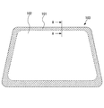
- FIG. 1A is a plan view of a laminated glass that is a laminated sheet according to an embodiment of the present invention.
- FIG. 1B is a plan view showing an example in which the laminated glass of one embodiment of the present invention is applied to a windshield of a vehicle.
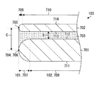
- FIG. 2 is a cross-sectional view (AA cross-sectional view) orthogonal to the outer peripheral edge in at least part of the outer peripheral edge of the laminated glass of the first embodiment of the present invention.
- the laminated glass 103 has a peripheral region 101 and an in-plane region 102 in plan view.
- the laminated glass 103 includes a first glass plate 201 and a second glass plate 202 bonded to the first glass plate 201 via an intermediate film 203.
- the first glass plate 201 includes a chamfered first chamfered region 207 on the periphery.
- the first glass plate 201 includes a first non-chamfered region 208 on the inner surface adjacent to the first chamfered region 207.
- the second glass plate 202 includes a chamfered second chamfer region 209 on the periphery.
- the second glass plate 202 includes a second non-chamfered region 210 on the inner surface adjacent to the second chamfered region 209.
- the peripheral area 101 is a more surface of the boundary between the first chamfered area 207 and the first non-chamfered area 208 or the boundary between the second chamfered area 209 and the second non-chamfered area 210 from the outer peripheral edge of the laminated glass 103.
- the in-plane region 102 refers to a region that occupies the inside of the peripheral region.
- the first glass plate 201 includes a first main surface 211 disposed on the side opposite to the intermediate film 203 and a second main surface 212 in contact with the intermediate film 203.
- the second glass plate 202 includes a third main surface 213 in contact with the intermediate film 203 and a fourth main surface 214 disposed on the side opposite to the intermediate film 203.
- the intermediate film 203 is not particularly limited.
- a single-layer intermediate film or an intermediate film in which a plurality of layers are superimposed may be used.
- an intermediate film having a plate thickness different depending on a part, such as a wedge shape in cross section, may be used.
- the present application is not limited to laminated glass in which two glass plates are laminated. It may be a laminated glass in which two or more glass plates are bonded via an intermediate film.
- the thickness of the first glass plate 201 is thicker than the thickness of the second glass plate 202.
- the thickness of the second glass plate 202 is preferably 0.2 mm or more and 1.0 mm or less, more preferably 0.3 mm or more and 0.8 mm or less, and further preferably 0.4 mm or more and 0.7 mm or less. is there.
- the laminated glass 103 can be reduced in weight by setting the thickness of the second glass plate 202 to 1.0 mm or less. Further, by setting the thickness of the second glass plate 202 to 0.2 mm or more, the bending rigidity is increased, and the operator can easily handle the second glass plate 202 during transportation.
- the thickness of the second glass plate 202 is preferably 0.4 mm or more and 1.8 mm or less, more preferably 0.5 mm or more and 1.6 mm or less, and further preferably 0.7 mm or more and 1. It is 6 mm or less, More preferably, it is 0.8 mm or more and 1.3 mm or less.
- board thickness of the 1st glass plate 201 is 1.7 mm or more and 4.0 mm or less, More preferably, it is 2.0 mm or more and 3.7 mm or less, More preferably, it is 2.5 mm or more and 3.5 mm or less. is there.
- the laminated glass 103 can be reduced in weight by setting the thickness of the first glass plate 201 to 4.0 mm or less. Moreover, sufficient bending rigidity is obtained for the laminated glass 103 by setting the thickness of the first glass plate 201 to 1.5 mm or more.
- the thickness of the first glass plate 201 is preferably 1.5 mm or more and 3.5 mm or less, preferably 1.5 mm or more and 2.8 mm or less, more preferably 1.5 mm. It is 2.5 mm or less.
- the value obtained by dividing the thickness of the second glass plate 202 by the thickness of the first glass plate 201 is preferably 0.1 or more and 0.5 or less, more preferably 0.13 or more and 0.48. Hereinafter, it is more preferably 0.15 or more and 0.45 or less.
- the laminated glass 103 having high rigidity and light weight can be obtained. .
- the value obtained by dividing the thickness of the second glass plate 202 by the thickness of the first glass plate 201 is preferably 0.5 or more and 0.9 or less, more preferably, It is 0.55 or more and 0.85 or less, more preferably 0.6 or more and 0 or 8 or less.
- the laminated glass which can suppress the reduction in sound insulation while reducing the weight when the value obtained by dividing the thickness of the second glass plate 202 by the thickness of the first glass plate 201 is 0.5 or more and 0.9 or less. 103 is obtained.
- a resin frame body may be attached to the outer peripheral edge of the laminated glass 103.
- the thickness direction at the end point 205 from the end point 205 of the second glass plate 202 to the first glass plate 201 in a cross section (AA cross section) orthogonal to the outer peripheral edge Is within 3 times the distance B between the first glass plate 201 and the second glass plate 202 in the in-plane region 102.
- the distance C is within 2.5 times the distance B, more preferably within 2.3 times, even more preferably within 2 times, even more preferably within 1.8 times, and even more preferably within 1.5 times. .
- the first viewpoint is suppression of foaming due to peeling of the laminated glass 103 from the outer peripheral edge.
- the first glass plate 201 and the second glass plate 202 are peeled from the outer peripheral edge. Therefore, if the distance C is within the above range at the outer peripheral edge, the intermediate film 203 and the first glass plate 201 and Intrusion of air from between the second glass plates 202 can be suppressed.
- the second viewpoint is suppression of foaming from the vicinity of the peripheral area 101 and / or the peripheral area 101 in the in-plane area 102. If the second glass plate 202 is thinner than the first glass plate 201, the rigidity of the second glass plate 202 is lower than the rigidity of the first glass plate 201. Therefore, for example, when a force is applied to compress the vicinity of the outer peripheral edge of the laminated glass 103 in the thickness direction, the end point 205 of the second glass plate 202 is on the first glass plate 201 side as shown in FIG. The second glass plate 202 bends so as to approach.
- the location E where the peeling force is generated is likely to occur not in the outer periphery but in the vicinity of the peripheral region 101 in the peripheral region 101 and / or the in-plane region 102.
- the occurrence point E in FIG. 8 is drawn with emphasis on the phenomenon.
- the second glass plate 202 is not deformed so as to swell in the thickness direction at the point E where the peeling force is generated.
- peripheral portion refers to a portion including the outer peripheral edge and the location E where the peeling force is generated.
- the force that compresses the vicinity of the outer peripheral edge of the laminated glass 103 in the thickness direction includes, for example, the force applied when vacuum-bonding in the laminated glass production process, the force applied when sandwiched between window frames, and the like.
- end point 205 of the second glass plate 202 is located on the inner side of the laminated glass 103 than the end point 204 of the first glass plate 201.
- end point 205 of the second glass plate 202 is in the first chamfered region 207 in plan view.
- the end point 205 of the second glass plate 202 is in the first chamfered region 207 in plan view, the end point 205 of the second glass plate 202 is difficult to be recognized by a person as a line or streak in plan view. , Can suppress a decrease in aesthetics.
- the step between the first glass plate 201 and the second glass plate 202 can be provided on the outer peripheral edge side, there are less problems due to catching at the time of wiping and cleaning the window due to the step and interference with other members. .
- the distance D is not particularly limited because it is determined according to the thickness difference between the first glass plate 201 and the second glass plate 202 and how close the distance C is to the distance B.
- the distance D is 1 mm or less.
- it is 0.8 mm or less, more preferably 0.6 mm or less.
- the first glass plate 201 and the second glass plate 202 may be bent by a conventionally known bending method.
- the first glass plate 201 and the second glass plate 202 may be stacked and placed on a ring-shaped mold, heated to a softening point or higher, and bent by its own weight.
- the first glass plate 201 and the second glass plate 202 may be press-molded in a heated state or in layers.
- a laminated glass 103 in which a first glass plate 201 curved into a first curved shape and a second glass plate 202 having a second shape different from the first curved shape are joined by an intermediate film 203 is provided. Also good.
- Such a laminated glass 103 is joined in a state where either one of the two glass plates or the two glass plates are elastically deformed to each other (hereinafter, either one of the two glass plates, Alternatively, a method for producing a laminated glass in which two glass plates are joined by elastic deformation of each other is also referred to as “cold bend”).
- FIG. 3 shows a state of the first glass plate 201 and the second glass plate 202 before being joined by the intermediate film 203.
- FIG. 4 shows the laminated glass 103 after being joined by the intermediate film 203 from the state of FIG.
- a cross section in which the radius of curvature of the first main surface 211 is the maximum is a cross section.
- the second main surface 212 has a smaller radius of curvature than the third main surface 213 in the cross section corresponding to the cross section.
- the cross section in which the radius of curvature of the first main surface 211 is maximum is the cross section including the normal line at the center of gravity of the laminated glass 103.
- the cross section is orthogonal to the cross section.
- the cross section to be taken is a vertical cross section
- the second main surface 212 is more than the third main surface 213 in both the cross section corresponding to the horizontal cross section and the cross section corresponding to the vertical cross section when the bonding by the intermediate film 203 is released.
- the laminated glass 103 in which the first glass plate 201 curved in the first curved shape and the second glass plate 202 having a second shape different from the first curved shape are joined by the intermediate film 203 is obtained.
- bending stress due to elastic deformation due to elastic deformation.
- the second glass plate 202 is bonded in a state of being mainly elastically deformed, so that the bending stress is applied to the second glass plate 202. Is formed.
- a bending compressive stress is formed in the peripheral region 101 of the second glass plate 202, and a bending tensile stress is formed near the center of the in-plane region 102 of the second glass plate 202.
- the bending compressive stress and bending tensile stress can be measured with a commercially available surface stress meter.
- both residual stress and bending stress are generated on the fourth main surface 214 of the second glass plate 202. Residual stress is due to strengthening and occurs before joining.
- the bending stress can be calculated by measuring the stress value after bonding and subtracting the stress value of the second glass plate 202 in the natural state from the measured value.
- the chemically strengthened flat plate-like second glass plate 202 is bonded to the first glass plate 201 via an intermediate film.
- the first glass plate 201 may be a double-curved shape bent in two orthogonal directions
- the second glass plate 202 may be a flat plate shape.
- the following advantages can be obtained by using a method for manufacturing laminated glass in which either one of two glass plates is elastically deformed and bonded. That is, conventionally, in order to obtain a curved laminated glass having a functional film formed, after forming a functional film on one or both of two flat glass plates before molding, There has been known a method in which a glass plate is heated to the vicinity of the softening point, bent, and bonded. However, in this method, the functional film may be heated to near the softening point of the glass plate, thereby reducing the function.
- the functional film reaches the vicinity of the softening point of the glass plate. Since a curved laminated glass can be obtained without heating, the function of the functional film can be sufficiently exhibited.
- a functional film is formed on the surface after the glass plate is bent into a desired curved shape.
- this method is more difficult than forming a functional film on a flat glass plate, and the process and apparatus are complicated. If a cold bend is used, since a functional film can be formed on the flat plate-like second glass plate 202, the process and apparatus can be simplified.
- the step of heating and bending the second glass plate 202 to the vicinity of the softening point can be omitted.
- the thickness of the second glass plate 202 is 1 mm or less, the degree of difficulty of maintaining the accuracy of bending by heating increases, so the effect is great.
- the second glass plate 202 used in the cold bend may have a second curved shape different from the first curved shape.
- the radius of curvature of the second curved shape is larger than the radius of curvature of the first curved shape.
- the second glass plate 202 may be bent into a second curved shape by bending with heating, or may be bent in the process of chemical strengthening.
- bending forming in the process of chemical strengthening means that the third main surface 213 is convex and fourth by making the way of chemical strengthening of the third main surface 213 larger than the fourth main surface 214.
- the second glass plate 202 can be bent so that the main surface 214 is concave.
- the step of heating and bending the second glass plate 202 to the vicinity of the softening point can be omitted.
- the second glass plate 202 has a curved shape, the difference in radius of curvature from the first curved shape is reduced, so that bending stress generated during cold bending can be reduced.
- the amount of Na on the third main surface 213 indicates the intensity of the K ⁇ orbit measured by X-ray fluorescence (XRF), and indicates the amount of Na from the surface of the third main surface 213 to a depth of 3 ⁇ m. .
- XRF X-ray fluorescence
- the cold bend includes a laminated body of a first glass plate 201, a second glass plate 202 and an intermediate film fixed by a temporary fixing means such as a tape, a conventionally known pre-pressing device such as a nip roller or a rubber bag, and an autoclave. It can be achieved by using it.
- the first cross-sectional shape of the first chamfered region 207 and the second cross-sectional shape of the second chamfered region 209 in a cross-sectional view are formed by an arc-shaped chamfered portion chamfered in an arc shape.
- the first cross-sectional shape of the first chamfered region 207 and the second cross-sectional shape of the second chamfered region 209 are different from each other.
- the radius of curvature of the arc-shaped chamfered portion is the direction of the first glass plate 201. Is larger and the second glass plate 202 is smaller.
- the first glass plate 201 and the second glass plate 202 are independently designed for chamfering. It can be performed.
- the present invention is not limited to this, and the first cross-sectional shape and the second cross-sectional shape may be chamfered with the same radius of curvature. If it is chamfered with the same curvature radius, it is not necessary to replace the grindstone at the time of manufacture between the first glass plate 201 and the second glass plate 202, and the manufacture and management of the grindstone are facilitated.
- the first cross-sectional shape and the second cross-sectional shape may be similar or different.
- chamfering using a high mesh diamond wheel may be performed or mirror finishing may be performed in order to improve the appearance quality and the strength of the outer peripheral edge.
- the intermediate film 203 may be cut off. That is, the intermediate film 203 may be present on the in-plane region 102 side with respect to the end portion 205 of the second glass plate 202.
- FIG. 5 is an AA cross-sectional view of the laminated glass of the second embodiment of the present invention.
- members having the same configurations as those shown in the first embodiment are denoted by the same reference numerals as in FIGS. 1A to 2, and description thereof is omitted.
- the chamfered shape of the first glass plate is different from that of the first embodiment.
- the first glass plate 501 has an arc-shaped chamfered portion 503 that is chamfered in an arc shape and a linear chamfered portion 504 that is chamfered in a linear shape.
- the linear chamfered portion 504 is formed so that the arc-shaped chamfered portion connects the 503 and the first non-chamfered region 208.
- the first tangent 502 (straight chamfered portion 504) at the boundary between the first chamfered region 207 and the first non-chamfered region 208 of the second main surface 212 intersects the second main surface 212 at the first angle ⁇ .
- the first angle ⁇ is preferably larger than 0 degree and not larger than 40 degrees. More preferably, the first angle ⁇ is not less than 5 degrees and not more than 35 degrees, more preferably not less than 8 degrees and not more than 30 degrees.
- the distance C becomes extremely large even if the end portion 205 of the second glass plate 202 is brought close to the end point 204 of the first glass plate 501 in order to reduce the distance D. Can be suppressed.
- the end face shape of the grindstone and the glass end can be stably rubbed together, so that the glass plate can be prevented from being broken during the manufacturing process.
- the length of the linear chamfered portion 504 is preferably 0.05 mm or more, more preferably 0.1 mm or more, and further preferably 0.15 mm or more. By doing in this way, distance D can also be made small, while making distance C small.
- the distance C can be reduced and the distance D can be reduced. That is, foaming at the peripheral edge portion of the laminated glass 103 can be suppressed, and a decrease in aesthetics, catching on and interference with other members can be suppressed.
- the first angle ⁇ is determined, it is 0 degree.
- the straight chamfered portion 504 includes not only a strict straight line but also an arc shape that can be approximated to a straight line.
- the arc shape that can be approximated to a substantially straight line is not particularly limited, but, for example, the arrow height is 10 ⁇ 1 or less.
- the first cross-sectional shape is exemplified as a symmetric shape centered on a line passing through the center of the thickness of the first glass plate 501 and parallel to the first and second main surfaces 211 and 212. It may be asymmetric.
- the angle formed between the tangent line at the boundary between the first chamfered region 207 and the first non-chamfered region 208 and the first main surface may be the same as the first angle ⁇ . It may be different.
- the second glass plate 202 may have a chamfered shape as in the present embodiment.
- FIG. 6 is an AA cross-sectional view of the laminated glass of the third embodiment of the present invention.
- members having the same configuration as the members shown in the first embodiment are denoted by the same reference numerals as in FIGS. 1A to 2, and description thereof is omitted.
- the chamfered shape of the first glass plate is different from that of the first embodiment.
- the first cross-sectional shape is asymmetric about a line passing through the center of the thickness of the first glass plate 601 and parallel to the first and second main surfaces 211 and 212.
- the position G of the boundary between the first chamfered region 207 and the first non-chamfered region 208 on the first main surface 211 side is the same as the first chamfered region 207 and the first chamfered region 207 on the second main surface 212 side. It is on the in-plane region 102 side from the position F of the boundary with the non-chamfered region 208.
- the distance C can be reduced while the distance C can be reduced. That is, foaming at the peripheral edge portion of the laminated glass 103 can be suppressed, and a decrease in aesthetics, catching on and interference with other members can be suppressed.
- the end point 204 of the first glass plate 601 is on the second main surface 212 side. Since the first main surface 211 side easily slides and interferes with other members, the end point 204 of the first glass plate 601 is provided by providing the end point 204 of the first glass plate 601 on the second main surface 212 side. Can be prevented from being overloaded.
- an exposed portion in which the peripheral portion of the laminated glass 103 is not covered with another member such as a resin frame For example, when a resin frame is attached to the peripheral edge of the laminated glass 103, since the end face is covered, foaming hardly occurs in the first place, and even if foaming occurs, it is concealed. However, in the case of an exposed portion, since the end surface is exposed, foaming is likely to occur, and when foaming occurs, it is likely to be a problem in appearance quality. Play.
- the “exposed portion” refers to a portion where at least one of the front and back surfaces of the peripheral portion of the laminated glass 103 and the end face of the intermediate film are exposed to the outside. Even if the front and back surfaces and the black shielding film are provided on the peripheral portion, the exposed portion is defined as long as it is not covered with another member such as a resin frame.
- the present invention relates to a laminated plate, and is particularly suitably used for laminated glass in which a glass plate is bonded via an intermediate film.
Abstract
Priority Applications (4)
| Application Number | Priority Date | Filing Date | Title |
|---|---|---|---|
| CN201680074494.5A CN108367981B (zh) | 2015-12-21 | 2016-12-12 | 层叠板 |
| EP16878451.0A EP3395777B1 (fr) | 2015-12-21 | 2016-12-12 | Stratifié |
| JP2017557884A JP6834983B2 (ja) | 2015-12-21 | 2016-12-12 | 積層板 |
| US16/007,525 US10953636B2 (en) | 2015-12-21 | 2018-06-13 | Laminated plate |
Applications Claiming Priority (2)
| Application Number | Priority Date | Filing Date | Title |
|---|---|---|---|
| JP2015-248204 | 2015-12-21 | ||
| JP2015248204 | 2015-12-21 |
Related Child Applications (1)
| Application Number | Title | Priority Date | Filing Date |
|---|---|---|---|
| US16/007,525 Continuation US10953636B2 (en) | 2015-12-21 | 2018-06-13 | Laminated plate |
Publications (1)
| Publication Number | Publication Date |
|---|---|
| WO2017110560A1 true WO2017110560A1 (fr) | 2017-06-29 |
Family
ID=59090249
Family Applications (1)
| Application Number | Title | Priority Date | Filing Date |
|---|---|---|---|
| PCT/JP2016/086925 WO2017110560A1 (fr) | 2015-12-21 | 2016-12-12 | Stratifié |
Country Status (5)
| Country | Link |
|---|---|
| US (1) | US10953636B2 (fr) |
| EP (1) | EP3395777B1 (fr) |
| JP (1) | JP6834983B2 (fr) |
| CN (1) | CN108367981B (fr) |
| WO (1) | WO2017110560A1 (fr) |
Cited By (4)
| Publication number | Priority date | Publication date | Assignee | Title |
|---|---|---|---|---|
| JP2019119285A (ja) * | 2017-12-28 | 2019-07-22 | 日本板硝子株式会社 | ウインドシールド |
| CN111758063A (zh) * | 2017-11-21 | 2020-10-09 | 康宁公司 | 用于抬头显示器系统的非球面镜及其形成方法 |
| EP3712119A4 (fr) * | 2018-05-21 | 2021-04-07 | Lg Chem, Ltd. | Procédé de fabrication de verre feuilleté incurvé et verre feuilleté incurvé ainsi fabriqué |
| US11919396B2 (en) | 2017-09-13 | 2024-03-05 | Corning Incorporated | Curved vehicle displays |
Families Citing this family (8)
| Publication number | Priority date | Publication date | Assignee | Title |
|---|---|---|---|---|
| CN109416480B (zh) | 2016-07-05 | 2022-08-12 | 康宁公司 | 冷成形玻璃制品和其组装工艺 |
| EP3507092A2 (fr) | 2017-01-03 | 2019-07-10 | Corning Incorporated | Systèmes d'intérieur de véhicule présentant un verre de couverture incurvé et écran ou panneau tactile et leurs procédés de formation |
| US11459268B2 (en) | 2017-09-12 | 2022-10-04 | Corning Incorporated | Tactile elements for deadfronted glass and methods of making the same |
| JP7471278B2 (ja) * | 2018-08-31 | 2024-04-19 | ピルキントン グループ リミテッド | 積層ガラス |
| US11772361B2 (en) | 2020-04-02 | 2023-10-03 | Corning Incorporated | Curved glass constructions and methods for forming same |
| FR3119112B1 (fr) | 2021-01-27 | 2023-01-20 | Saint Gobain | vitrage FEUILLETE COULISSANT A RETRAIT INTERIEUR ET PROCEDE DE FABRICATION DE CE VITRAGE |
| CN113320358B (zh) * | 2021-06-25 | 2022-07-01 | 长春工程学院 | 一种智能汽车安全驾驶装置 |
| CN114193876B (zh) * | 2021-10-25 | 2022-08-09 | 福耀玻璃工业集团股份有限公司 | 透光组件、夹层玻璃结构、车辆及加工方法 |
Citations (4)
| Publication number | Priority date | Publication date | Assignee | Title |
|---|---|---|---|---|
| JP2003048763A (ja) * | 2001-08-01 | 2003-02-21 | Nippon Sheet Glass Co Ltd | 防犯用ガラスパネル |
| WO2011048978A1 (fr) * | 2009-10-20 | 2011-04-28 | 旭硝子株式会社 | Stratifié-verre, panneau de dispositif d'affichage à corps de support, panneau de dispositif d'affichage, dispositif d'affichage, procédé de fabrication de stratifié-verre, procédé de fabrication d'un panneau de dispositif d'affichage à corps de support, et procédé de fabrication d'un panneau de dispositif d'affichage |
| JP2013129552A (ja) | 2011-12-20 | 2013-07-04 | Central Glass Co Ltd | 車両用合わせガラス及びその製造方法 |
| WO2014098160A1 (fr) * | 2012-12-19 | 2014-06-26 | 旭硝子株式会社 | Verre feuilleté |
Family Cites Families (25)
| Publication number | Priority date | Publication date | Assignee | Title |
|---|---|---|---|---|
| US2092789A (en) * | 1934-09-13 | 1937-09-14 | American Optical Corp | Glass treatment |
| US3282772A (en) * | 1965-06-28 | 1966-11-01 | Libbey Owens Ford Glass Co | Laminated glass |
| JPS5854316A (ja) | 1981-09-25 | 1983-03-31 | Sharp Corp | 液晶表示装置の製造方法 |
| JP2000252342A (ja) | 1999-03-01 | 2000-09-14 | Seiko Epson Corp | 薄板の搬送方法および液晶パネルの製造方法 |
| FR2793106B1 (fr) * | 1999-04-28 | 2001-06-22 | Saint Gobain Vitrage | Vitrage multiple isolant, en particulier hublot d'avion, a blindage electromagnetique |
| US6325704B1 (en) | 1999-06-14 | 2001-12-04 | Corning Incorporated | Method for finishing edges of glass sheets |
| JP2002154321A (ja) | 2000-11-17 | 2002-05-28 | Asahi Glass Co Ltd | 自動車用ガラス板および自動車用ガラス板の製造方法 |
| US6733872B2 (en) * | 2001-03-01 | 2004-05-11 | Asahi Glass Company, Limited | Laminated glass |
| JP5109228B2 (ja) | 2005-02-08 | 2012-12-26 | 旭硝子株式会社 | 薄板ガラス積層体及び薄板ガラス積層体を用いた表示装置の製造方法 |
| WO2007018028A1 (fr) | 2005-08-09 | 2007-02-15 | Asahi Glass Company, Limited | Produit stratifié de verre en fine feuille et procédé destiné à fabriquer un affichage employant un tel produit |
| JP2007223883A (ja) | 2005-12-26 | 2007-09-06 | Asahi Glass Co Ltd | 車両用合せガラス |
| JP2007197288A (ja) * | 2006-01-30 | 2007-08-09 | Nippon Sheet Glass Co Ltd | 合わせガラス及びこれを用いたガラス窓構造 |
| JP5024087B2 (ja) | 2008-02-05 | 2012-09-12 | 旭硝子株式会社 | ガラス積層体、支持体付き表示装置用パネル、およびそれらの製造方法 |
| CN102007524B (zh) | 2008-04-17 | 2013-07-31 | 旭硝子株式会社 | 玻璃层叠体、带支撑体的显示装置用面板及它们的制造方法 |
| JP5251336B2 (ja) * | 2008-07-30 | 2013-07-31 | セントラル硝子株式会社 | 湾曲ロールを用いた合わせガラスの予備接着方法および装置 |
| JP5616907B2 (ja) * | 2009-03-02 | 2014-10-29 | アップル インコーポレイテッド | ポータブル電子デバイスのガラスカバーを強化する技術 |
| JP2012526040A (ja) * | 2009-05-08 | 2012-10-25 | コーニング インコーポレイテッド | ポリマーの外側被覆を有するガラス物品およびその形成方法 |
| KR101538835B1 (ko) * | 2010-01-25 | 2015-07-22 | 아사히 가라스 가부시키가이샤 | 적층체의 제조 방법 및 적층체 |
| EP2708355B1 (fr) * | 2011-05-13 | 2020-12-02 | Nippon Electric Glass Co., Ltd. | Stratifié et procédé pour sa fabrication |
| US20140014260A1 (en) * | 2012-07-12 | 2014-01-16 | Dipakbin Qasem Chowdhury | Laminated structures and methods of manufacturing laminated structures |
| EP2738512B1 (fr) * | 2012-11-29 | 2019-02-20 | ISOCLIMA S.p.A. | Structure de fenêtre blindée |
| US11077607B2 (en) | 2013-10-21 | 2021-08-03 | Made In Space, Inc. | Manufacturing in microgravity and varying external force environments |
| JP2015096313A (ja) * | 2013-11-15 | 2015-05-21 | 日本電気硝子株式会社 | ガラスフィルム積層体および液晶パネルの製造方法 |
| CA2946359C (fr) * | 2014-05-06 | 2018-06-19 | Saint-Gobain Glass France | Plaque de verre feuilletee comportant un joint de bord et procede de fabrication |
| JP6787066B2 (ja) * | 2016-01-05 | 2020-11-18 | Agc株式会社 | 積層板 |
-
2016
- 2016-12-12 CN CN201680074494.5A patent/CN108367981B/zh active Active
- 2016-12-12 EP EP16878451.0A patent/EP3395777B1/fr active Active
- 2016-12-12 JP JP2017557884A patent/JP6834983B2/ja active Active
- 2016-12-12 WO PCT/JP2016/086925 patent/WO2017110560A1/fr active Application Filing
-
2018
- 2018-06-13 US US16/007,525 patent/US10953636B2/en active Active
Patent Citations (4)
| Publication number | Priority date | Publication date | Assignee | Title |
|---|---|---|---|---|
| JP2003048763A (ja) * | 2001-08-01 | 2003-02-21 | Nippon Sheet Glass Co Ltd | 防犯用ガラスパネル |
| WO2011048978A1 (fr) * | 2009-10-20 | 2011-04-28 | 旭硝子株式会社 | Stratifié-verre, panneau de dispositif d'affichage à corps de support, panneau de dispositif d'affichage, dispositif d'affichage, procédé de fabrication de stratifié-verre, procédé de fabrication d'un panneau de dispositif d'affichage à corps de support, et procédé de fabrication d'un panneau de dispositif d'affichage |
| JP2013129552A (ja) | 2011-12-20 | 2013-07-04 | Central Glass Co Ltd | 車両用合わせガラス及びその製造方法 |
| WO2014098160A1 (fr) * | 2012-12-19 | 2014-06-26 | 旭硝子株式会社 | Verre feuilleté |
Cited By (8)
| Publication number | Priority date | Publication date | Assignee | Title |
|---|---|---|---|---|
| US11919396B2 (en) | 2017-09-13 | 2024-03-05 | Corning Incorporated | Curved vehicle displays |
| CN111758063A (zh) * | 2017-11-21 | 2020-10-09 | 康宁公司 | 用于抬头显示器系统的非球面镜及其形成方法 |
| EP3714316A4 (fr) * | 2017-11-21 | 2021-08-04 | Corning Incorporated | Miroir asphérique pour système d'affichage tête haute et ses procédés de formation |
| CN111758063B (zh) * | 2017-11-21 | 2022-08-09 | 康宁公司 | 用于抬头显示器系统的非球面镜及其形成方法 |
| US11768369B2 (en) | 2017-11-21 | 2023-09-26 | Corning Incorporated | Aspheric mirror for head-up display system and methods for forming the same |
| JP2019119285A (ja) * | 2017-12-28 | 2019-07-22 | 日本板硝子株式会社 | ウインドシールド |
| EP3712119A4 (fr) * | 2018-05-21 | 2021-04-07 | Lg Chem, Ltd. | Procédé de fabrication de verre feuilleté incurvé et verre feuilleté incurvé ainsi fabriqué |
| US11242285B2 (en) | 2018-05-21 | 2022-02-08 | Lg Chem, Ltd. | Method of manufacturing curved joined glass sheet and curved joined glass sheet manufactured by the same |
Also Published As
| Publication number | Publication date |
|---|---|
| EP3395777A4 (fr) | 2019-07-31 |
| EP3395777B1 (fr) | 2021-04-07 |
| JP6834983B2 (ja) | 2021-02-24 |
| US20180290438A1 (en) | 2018-10-11 |
| US10953636B2 (en) | 2021-03-23 |
| CN108367981A (zh) | 2018-08-03 |
| JPWO2017110560A1 (ja) | 2018-10-04 |
| EP3395777A1 (fr) | 2018-10-31 |
| CN108367981B (zh) | 2021-01-15 |
Similar Documents
| Publication | Publication Date | Title |
|---|---|---|
| WO2017110560A1 (fr) | Stratifié | |
| JP6787066B2 (ja) | 積層板 | |
| US20200180275A1 (en) | Stiff interlayers for laminated glass structures | |
| JP6031099B2 (ja) | 自動車のための窓ガラス | |
| KR20150036499A (ko) | 적층 구조 및 적층 구조의 제조방법 | |
| JP6720741B2 (ja) | 積層板および中間膜 | |
| WO2017090562A1 (fr) | Verre feuilleté | |
| WO2018079230A1 (fr) | Verre feuilleté | |
| WO2019058944A1 (fr) | Verre feuilleté pour pare-brise automobile | |
| JP6658760B2 (ja) | 透明スクリーン、透明スクリーン組立体、透明スクリーンの製造方法、および透明スクリーン組立体の製造方法 | |
| JP6531756B2 (ja) | 窓用積層基板、枠体付き窓用積層基板、窓用積層基板を備えた自動車及び窓用積層基板用中間層構造体 | |
| JP6774029B2 (ja) | ガラス樹脂積層体 | |
| JPWO2019012919A1 (ja) | 車両フロント窓用の合せガラス | |
| JP7211371B2 (ja) | 車両用窓ガラス | |
| WO2017159411A1 (fr) | Plaque en verre et structure en verre | |
| WO2021182522A1 (fr) | Vitre de véhicule et unité de caméra | |
| KR102650221B1 (ko) | 물성 향상을 위한 이종소재 접합형 금속 마감재 및 이의 제조방법 | |
| WO2012132897A1 (fr) | Verre feuilleté | |
| KR102650895B1 (ko) | 곡면 마감된 둘레부 인접영역을 가지는 이종소재 접합형 금속 마감재 및 이의 제조방법 | |
| WO2017159410A1 (fr) | Plaque en verre et structure en verre | |
| KR20110099522A (ko) | 건물의 내외벽재 대체용 유리벽의 구조 | |
| WO2017159412A1 (fr) | Plaque de verre et structure en verre | |
| JP2000001345A (ja) | 異層合せガラス板 | |
| CN117186788A (zh) | 一种ag屏幕保护膜及其膜制作方法 |
Legal Events
| Date | Code | Title | Description |
|---|---|---|---|
| 121 | Ep: the epo has been informed by wipo that ep was designated in this application |
Ref document number: 16878451 Country of ref document: EP Kind code of ref document: A1 |
|
| ENP | Entry into the national phase |
Ref document number: 2017557884 Country of ref document: JP Kind code of ref document: A |
|
| NENP | Non-entry into the national phase |
Ref country code: DE |
|
| WWE | Wipo information: entry into national phase |
Ref document number: 2016878451 Country of ref document: EP |
|
| ENP | Entry into the national phase |
Ref document number: 2016878451 Country of ref document: EP Effective date: 20180723 |