WO2017110491A1 - 有機性排水処理装置および有機性排水処理方法 - Google Patents
有機性排水処理装置および有機性排水処理方法 Download PDFInfo
- Publication number
- WO2017110491A1 WO2017110491A1 PCT/JP2016/086512 JP2016086512W WO2017110491A1 WO 2017110491 A1 WO2017110491 A1 WO 2017110491A1 JP 2016086512 W JP2016086512 W JP 2016086512W WO 2017110491 A1 WO2017110491 A1 WO 2017110491A1
- Authority
- WO
- WIPO (PCT)
- Prior art keywords
- zone
- membrane separation
- activated sludge
- aerobic
- tank
- Prior art date
- Legal status (The legal status is an assumption and is not a legal conclusion. Google has not performed a legal analysis and makes no representation as to the accuracy of the status listed.)
- Ceased
Links
Images





Classifications
-
- B—PERFORMING OPERATIONS; TRANSPORTING
- B01—PHYSICAL OR CHEMICAL PROCESSES OR APPARATUS IN GENERAL
- B01D—SEPARATION
- B01D61/00—Processes of separation using semi-permeable membranes, e.g. dialysis, osmosis or ultrafiltration; Apparatus, accessories or auxiliary operations specially adapted therefor
- B01D61/14—Ultrafiltration; Microfiltration
-
- C—CHEMISTRY; METALLURGY
- C02—TREATMENT OF WATER, WASTE WATER, SEWAGE, OR SLUDGE
- C02F—TREATMENT OF WATER, WASTE WATER, SEWAGE, OR SLUDGE
- C02F1/00—Treatment of water, waste water, or sewage
- C02F1/44—Treatment of water, waste water, or sewage by dialysis, osmosis or reverse osmosis
-
- C—CHEMISTRY; METALLURGY
- C02—TREATMENT OF WATER, WASTE WATER, SEWAGE, OR SLUDGE
- C02F—TREATMENT OF WATER, WASTE WATER, SEWAGE, OR SLUDGE
- C02F3/00—Biological treatment of water, waste water, or sewage
- C02F3/02—Aerobic processes
- C02F3/12—Activated sludge processes
-
- Y—GENERAL TAGGING OF NEW TECHNOLOGICAL DEVELOPMENTS; GENERAL TAGGING OF CROSS-SECTIONAL TECHNOLOGIES SPANNING OVER SEVERAL SECTIONS OF THE IPC; TECHNICAL SUBJECTS COVERED BY FORMER USPC CROSS-REFERENCE ART COLLECTIONS [XRACs] AND DIGESTS
- Y02—TECHNOLOGIES OR APPLICATIONS FOR MITIGATION OR ADAPTATION AGAINST CLIMATE CHANGE
- Y02W—CLIMATE CHANGE MITIGATION TECHNOLOGIES RELATED TO WASTEWATER TREATMENT OR WASTE MANAGEMENT
- Y02W10/00—Technologies for wastewater treatment
- Y02W10/10—Biological treatment of water, waste water, or sewage
Definitions
- the present invention relates to an organic wastewater treatment apparatus and an organic wastewater treatment method for treating organic wastewater in activated sludge.
- an anaerobic tank 101 for denitrifying treated water by anaerobic microorganisms, and treated water flowing from the anoxic tank 101 are included.
- a sewage treatment facility 104 that has an aerobic tank 102 that nitrifies ammonia to be aerobic microorganisms, and an air lift pump 103 that returns a portion of the water to be treated nitrified in the aerobic tank 102 to the anoxic tank 101.
- the aerobic tank 102 is installed on the downstream side of the anoxic tank 101 through the partition wall 105.
- the inside of the aerobic tank 102 is divided into a first region 107 and a second region 108 by a separation wall 106.
- a diffuser 109 is installed in the first area 107.
- a membrane separation device 110 for solid-liquid separation of the water to be treated is installed in the second region 108.
- the membrane separation device 110 has an air diffuser 111 at the bottom. Further, the air lift pump 103 is installed on the downstream side of the second region 108.
- the water to be treated is subjected to anaerobic treatment in the anaerobic tank 101 and then aerobic treatment in the first region 107 of the aerobic tank 102, and in the second region 108 by the membrane separation device 110. Solid-liquid separation.
- a part of the water to be treated in the second region 108 is returned to the oxygen-free tank 101 by the air lift pump 103, whereby the water to be treated passes through the first region 107 in the aerobic tank 102 from the oxygen-free tank 101. After flowing through the second region 108, it is processed while circulating from the second region 108 to the anoxic tank 101.
- the sludge adhering to the membrane surface of the membrane separation device 110 can be removed.
- An object of the present invention is to provide an organic wastewater treatment apparatus and an organic wastewater treatment method that can be reduced in size and cost.
- the present invention is a treatment apparatus for treating organic wastewater in activated sludge
- the inside of the treatment tank is partitioned by a partition member into a membrane separation zone, first and second anoxic zones, and first and second aerobic zones,
- the membrane separation area and the first oxygen-free area communicate at the top
- the membrane separation zone and the second oxygen-free zone communicate at the top
- the membrane separation area and the first aerobic area communicate with each other at the bottom
- the membrane separation area and the second aerobic area communicate at the bottom
- the first anoxic zone and the first aerobic zone communicate with each other;
- the second anoxic zone and the first aerobic zone communicate with each other;
- the first anaerobic zone and the second aerobic zone communicate with each other;
- the second anoxic zone and the second aerobic zone communicated
- a membrane separation device immersed in activated sludge and equipped with an air diffuser at the bottom is arranged, The activated sludge that has passed through the membrane separator as an upward flow due to the air diffused from the air
- the activated sludge that has passed through the membrane separation device as an upward flow is branched from the membrane separation zone and flows into the first and second oxygen-free zones by performing aeration with the diffusion device of the membrane separation device.
- a part of the activated sludge that has passed through the first oxygen-free zone and a part of the activated sludge that has passed through the second oxygen-free zone flow into the first aerobic zone, and the remainder of the activated sludge that has passed through the first oxygen-free zone;
- the remainder of the activated sludge that has passed through the second anaerobic zone flows into the second aerobic zone, the activated sludge in the first aerobic zone and the activated sludge in the second aerobic zone flow into the membrane separation zone and become an upward flow,
- Activated sludge circulates in the tank.
- sludge adhering to the membrane surface of the membrane separator can be removed by aeration with the diffuser of the membrane separator.
- the air diffuser of the membrane separation device serves as both the power generation means for circulating the activated sludge in the tank as described above and the membrane surface cleaning means of the membrane separation device. Therefore, it is not necessary to separately install power generation means for circulating activated sludge such as an air lift pump or a submersible pump, and the organic waste water treatment apparatus can be reduced in size and cost.
- activated sludge repeats branching and merging in the middle of circulating in the treatment tank, so that complete mixing of activated sludge in the treatment tank is promoted and the biological treatment efficiency of the organic waste water treatment equipment is increased. Can do.
- the membrane separation device has a plurality of flat membrane elements arranged at predetermined intervals in a vertical posture above the air diffuser,
- the first and second anoxic zones are arranged such that the activated sludge branches off from the membrane separation zone and flows in a direction perpendicular to the arrangement direction of the flat membrane elements,
- the first and second aerobic zones are arranged such that activated sludge flows into the membrane separation zone along the arrangement direction of the flat membrane elements.
- the activated sludge flows upward and downward between the flat membrane elements by performing the aeration with the aeration device of the membrane separation device.
- the upward flow that has passed between the flat membrane elements branches from the membrane separation zone in a direction perpendicular to the direction in which the flat membrane elements are arranged, and flows into the first and second oxygen-free zones.
- the activated sludge that has passed through the first and second oxygen-free zones flows from the first and second aerobic zones into the membrane separation zone along the arrangement direction of the flat membrane elements.
- the direction in which activated sludge flows from the membrane separation zone into the first and second anoxic zones is different from the direction in which activated sludge flows from the first and second aerobic zones into the membrane separation zone. Counterflow flows evenly between flat membrane elements. Thereby, it can prevent that sludge adheres locally to a part of flat membrane element.
- the organic waste water treatment apparatus in the present invention is connected to a raw water supply path for supplying organic waste water to the first and second anoxic zones.
- the amount of organic wastewater in the treatment tank can be kept at a predetermined amount by supplying organic wastewater to the first and second oxygen-free zones from the raw water supply path.
- the organic wastewater treatment apparatus in the present invention is a treatment apparatus for treating organic wastewater in activated sludge
- the inside of the treatment tank is divided into a membrane separation area, first and second oxygen-free areas, and an aerobic area by a partition member,
- the membrane separation area and the first oxygen-free area communicate at the top
- the membrane separation zone and the second oxygen-free zone communicate at the top
- the membrane separation area and the aerobic area communicate with each other at the bottom.
- the first anoxic zone and the aerobic zone communicate The second anoxic zone and the aerobic zone communicated
- a membrane separation device immersed in activated sludge and equipped with an air diffuser at the bottom is arranged,
- the activated sludge that has passed through the membrane separator as an upward flow due to the air diffused from the air diffuser branches in a direction away from the membrane separation zone and flows into the first and second oxygen-free zones,
- the activated sludge that has passed through the first oxygen-free zone and the activated sludge that has passed through the second oxygen-free zone flow into the aerobic zone, Activated sludge in the aerobic zone flows into the membrane separation zone.
- the activated sludge that has passed through the membrane separation device as an upward flow is branched from the membrane separation zone and flows into the first and second oxygen-free zones by performing aeration with the diffusion device of the membrane separation device.
- the activated sludge that has passed through the first oxygen-free zone and the activated sludge that has passed through the second oxygen-free zone flow into the aerobic zone, and the activated sludge in the aerobic zone flows into the membrane separation zone and becomes an upward flow.
- Activated sludge circulates.
- sludge adhering to the membrane surface of the membrane separator can be removed by aeration with the diffuser of the membrane separator.
- the air diffuser of the membrane separation device serves as both the power generation means for circulating the activated sludge in the tank as described above and the membrane surface cleaning means of the membrane separation device. Therefore, it is not necessary to separately install power generation means for circulating activated sludge such as an air lift pump or a submersible pump, and the organic waste water treatment apparatus can be reduced in size and cost.
- activated sludge repeats branching and merging in the middle of circulating in the treatment tank, so that complete mixing of activated sludge in the treatment tank is promoted and the biological treatment efficiency of the organic waste water treatment equipment is increased. Can do.
- the organic wastewater treatment apparatus in the present invention is a treatment apparatus for treating organic wastewater in activated sludge
- the inside of the treatment tank is partitioned by a partition member into a membrane separation zone, first and second anoxic zones, and first and second aerobic zones,
- the membrane separation area and the first oxygen-free area communicate at the top
- the membrane separation zone and the second oxygen-free zone communicate at the top
- the membrane separation area and the first aerobic area communicate with each other at the bottom
- the membrane separation zone and the second aerobic zone communicate with each other at the lower part
- the first anoxic zone communicates with the first aerobic zone,
- the second anoxic zone and the second aerobic zone communicated
- a membrane separation device immersed in activated sludge and equipped with an air diffuser at the bottom is arranged,
- the activated sludge that has passed through the membrane separator as an upward flow due to the air diffused from the air diffuser branches in a direction away from the membrane separation zone and flows into the first and second oxygen-free zones,
- the activated sludge that has passed through the membrane separation device as an upward flow is branched from the membrane separation zone and flows into the first and second oxygen-free zones by performing aeration with the diffusion device of the membrane separation device.
- the activated sludge that has passed through the first anaerobic zone flows into the first aerobic zone
- the activated sludge that has passed through the second anaerobic zone flows into the second aerobic zone
- the activated sludge and the second in the first aerobic zone The activated sludge in the aerobic zone flows into the membrane separation zone and becomes an upward flow
- the activated sludge circulates in the tank.
- sludge adhering to the membrane surface of the membrane separator can be removed by aeration with the diffuser of the membrane separator.
- the air diffuser of the membrane separation device serves as both the power generation means for circulating the activated sludge in the tank as described above and the membrane surface cleaning means of the membrane separation device. Therefore, it is not necessary to separately install power generation means for circulating activated sludge such as an air lift pump or a submersible pump, and the organic waste water treatment apparatus can be reduced in size and cost.
- activated sludge repeats branching and merging in the middle of circulating in the treatment tank, so that complete mixing of activated sludge in the treatment tank is promoted and the biological treatment efficiency of the organic waste water treatment equipment is increased. Can do.
- the membrane separation apparatus has a plurality of flat membrane elements arranged at predetermined intervals in a vertical posture above the air diffuser.
- the activated sludge flows upward and downward between the flat membrane elements by performing the aeration with the aeration device of the membrane separation device. Thereby, the sludge adhering to the membrane surface of the flat membrane element can be removed.
- the present invention also provides an organic wastewater for treating organic wastewater in activated sludge using a treatment device in which a treatment tank is partitioned into a membrane separation zone, a first and second oxygen-free zone, and an aerobic zone.
- a processing method While taking out treated water from a submerged membrane separator placed in the membrane separation area, The activated sludge that has passed through the inside of the membrane separator due to the air diffused from the air diffuser provided at the lower part of the membrane separator is branched into one and the other treatment path, and flows.
- Activated sludge flowing through one treatment path passes through the first oxygen-free zone and is supplied to the aerobic zone,
- the activated sludge flowing through the other treatment path passes through the second anoxic zone and is supplied to the aerobic zone,
- the activated sludge from one treatment path and the activated sludge from the other treatment path that have joined together in the aerobic zone are introduced into the membrane separation zone.
- the activated sludge in the membrane separation area flows upward from below to generate an upward flow, and the activated sludge circulates in the tank, and the membrane Sludge adhering to the membrane surface of the separator can be removed.
- the air diffuser of the membrane separation device combines the power generation means for circulating the activated sludge in the tank and the membrane surface cleaning means of the membrane separation device. There is no need to separately install power generation means for circulating the activated sludge, and the organic waste water treatment apparatus can be reduced in size and cost.
- activated sludge repeats branching and merging in the middle of circulating in the treatment tank, so that complete mixing of activated sludge in the treatment tank is promoted and the biological treatment efficiency of the organic waste water treatment equipment is increased. Can do.
- the aerobic zone is separated into a first aerobic zone and a second aerobic zone
- the activated sludge flowing through one of the treatment paths branches to the first branch path and the second branch path when passing through the first oxygen-free zone, and is supplied to the first aerobic zone and the second aerobic zone.
- the activated sludge flowing through the other treatment path branches to the third branch path and the fourth branch path when passing through the second oxygen-free zone, and is supplied to the first aerobic zone and the second aerobic zone.
- Activated sludge from the first branch path and activated sludge from the third branch path are merged in the first aerobic zone and introduced into the membrane separation zone, and from the activated sludge from the second branch path and the fourth branch path The activated sludge is combined in the second aerobic zone and introduced into the membrane separation zone.
- the present invention also provides a method for treating organic wastewater in activated sludge using a treatment apparatus in which a treatment tank is partitioned into a membrane separation zone, first and second anoxic zones, and first and second aerobic zones.
- An organic wastewater treatment method for processing While taking out treated water from a submerged membrane separator placed in the membrane separation area, The activated sludge that has passed through the inside of the membrane separator due to the air diffused from the air diffuser provided at the lower part of the membrane separator is branched into one and the other treatment path, and flows.
- Activated sludge flowing through one treatment path is introduced into the membrane separation zone through the first anoxic zone and the first aerobic zone
- Activated sludge flowing through the other treatment path is introduced into the membrane separation zone through the second anoxic zone and the second aerobic zone
- the activated sludge introduced from one treatment path and the activated sludge introduced from the other treatment path are merged in the membrane separation section, and passed through the membrane separation apparatus in an upward flow by the diffused air from the diffuser. Is.
- the activated sludge in the membrane separation area flows upward from below to generate an upward flow, and the activated sludge circulates in the tank, and the membrane Sludge adhering to the membrane surface of the separator can be removed.
- the air diffuser of the membrane separation device combines the power generation means for circulating the activated sludge in the tank and the membrane surface cleaning means of the membrane separation device. There is no need to separately install power generation means for circulating the activated sludge, and the organic waste water treatment apparatus can be reduced in size and cost.
- activated sludge repeats branching and merging in the middle of circulating in the treatment tank, so that complete mixing of activated sludge in the treatment tank is promoted and the biological treatment efficiency of the organic waste water treatment equipment is increased. Can do.
- the direction in which the activated sludge that has passed through the membrane separator in an upward flow is branched into one and the other treatment path is a branch direction
- the direction in which the activated sludge in the first aerobic zone is introduced into the membrane separation zone is the first introduction direction
- the direction in which the activated sludge in the second aerobic zone is introduced into the membrane separation zone is the second introduction direction
- the organic wastewater treatment method in the present invention supplies organic wastewater to one and the other treatment path.
- the air diffusing device of the membrane separation device combines the power generation means for circulating the activated sludge in the tank and the membrane surface cleaning means of the membrane separation device.
- power generation means for circulating activated sludge such as a pump and a submersible pump, and the organic wastewater treatment apparatus can be reduced in size and cost.
- activated sludge repeats branching and merging in the middle of circulating in the treatment tank, so that complete mixing of activated sludge in the treatment tank is promoted and the biological treatment efficiency of the organic waste water treatment equipment is increased. Can do.
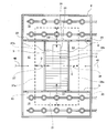
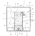
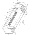
- FIG. 2 is a view on arrow XX in FIG. 1. It is the perspective view which notched a part of organic waste water treatment equipment same as the above.
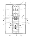
- FIG. 2 is a schematic plan view of the organic waste water treatment apparatus in the 2nd Embodiment of this invention. It is a schematic plan view of the organic waste water treatment apparatus in the 3rd Embodiment of this invention. It is a schematic plan view of the organic waste water treatment apparatus in the 4th Embodiment of this invention.
- reference numeral 1 denotes a treatment apparatus for treating organic wastewater such as sewage in activated sludge.
- the processing apparatus 1 has a processing tank 2, and the inside of the processing tank 2 is separated from the first and fourth partition walls 3 to 6 (an example of a partition member) by the membrane separation tank 11 (an example of a membrane separation area) and the first and The second anaerobic tanks 12 and 13 (an example of an anaerobic area) and the first and second aerobic tanks 14 and 15 (an example of an aerobic area) are partitioned.
- the membrane separation tank 11 is formed at the center of the treatment tank 2, and the first and second oxygen-free tanks 12 and 13 and the first and second aerobic tanks 14 and 15 are formed so as to surround the periphery of the membrane separation tank 11. Has been.
- the first and second oxygen-free tanks 12 and 13 are provided with a stirrer (not shown).
- the first and second aerobic tanks 14 and 15 are provided with an air diffuser 17 for supplying oxygen to the water 8 to be treated containing activated sludge.
- the first partition wall 3 is a wall that partitions the membrane separation tank 11 and the first oxygen-free tank 12
- the second partition wall 4 is a wall that partitions the membrane separation tank 11 and the second oxygen-free tank 13. is there.
- the upper ends of the first and second partition walls 3 and 4 are slightly below the water surface 8a of the water to be treated 8 (activated sludge) in the treatment tank 2, respectively.
- the membrane separation tank 11 and the first oxygen-free tank 12 communicate with each other at the upper part
- the membrane separation tank 11 and the second oxygen-free tank 13 communicate with each other at the upper part.
- the third partition wall 5 is provided between the membrane separation tank 11 and the first aerobic tank 14, between the first anaerobic tank 12 and the first aerobic tank 14, and between the second anoxic tank 13 and the first aerobic tank.
- the fourth partition wall 6 is provided between the membrane separation tank 11 and the second aerobic tank 15, between the first anaerobic tank 12 and the second aerobic tank 15, and between the second anaerobic tank 13 and the second aerobic tank 13.
- 2 is a wall that partitions the aerobic tank 15.
- the upper ends of the third and fourth partition walls 5 and 6 protrude upward from the water surface 8a of the water 8 to be treated in the treatment tank 2, respectively.
- a membrane separation device 27 immersed in the water to be treated 8 is disposed.
- the membrane separation device 27 includes a membrane filling unit 28, an air diffusion unit 29 formed below the membrane filling unit 28, a plurality of flat membrane elements 30 filled in the membrane filling unit 28, and the air diffusion unit 29. And an air diffuser 31 provided.
- the membrane filling portion 28 and the diffuser portion 29 communicate with each other in the vertical direction.
- the upper end of the film filling portion 28 is open.
- the flat membrane element 30 has a flat filter plate 33 and filter membranes 34 mounted on both sides of the filter plate 33, and is arranged above the air diffuser 31 with a predetermined interval in a vertical position. Has been.
- the treated water 36 (permeated water) that has passed through the filtration membrane 34 of each flat membrane element 30 is collected in the water collection pipe 35 and taken out of the treatment tank 2.
- three openings 19 to 21 are formed in the lower part of the third partition wall 5, and three openings 22 to 24 are also formed in the lower part of the fourth partition wall 6. Yes.
- the lower part of the 1st anaerobic tank 12 and the lower part of the 1st aerobic tank 14 are connected via the opening part 19, and the lower part of the 2nd anaerobic tank 13 and the lower part of the 1st aerobic tank 14 are connected.
- the diffuser 29 provided at the lower part of the membrane separation tank 11 and the lower part of the first aerobic tank 14 communicate with each other via the opening 20.
- the lower part of the first anaerobic tank 12 and the lower part of the second aerobic tank 15 communicate with each other through the opening 22, and the lower part of the second anaerobic tank 13 and the lower part of the second aerobic tank 15 are opened.
- the air diffuser 29 provided at the lower part of the membrane separation tank 11 and the lower part of the second aerobic tank 15 communicate with each other through the opening 24.
- the first aerobic tank 14 and the second aerobic tank 15 face each other in the arrangement direction A of the flat membrane elements 30 with the membrane separation tank 11 in between.
- the first oxygen-free tank 12 and the second oxygen-free tank 13 are opposed to each other in a direction B orthogonal to the arrangement direction A with the membrane separation tank 11 interposed therebetween.
- the first anaerobic tank 12 and the second anaerobic tank 13 are provided between the first aerobic tank 14 and the second aerobic tank 15 in the arrangement direction A.
- the water to be treated 8 branches and flows into one and the other treatment paths 37 and 38 and circulates in the treatment tank 2.
- One processing path 37 extends from the membrane separation tank 11 over the first partition wall 3 to the first oxygen-free tank 12, reaches from the upper part of the first oxygen-free tank 12 to the lower part, and the first oxygen-free tank 12.
- the first branch path 37a branches into the first aerobic tank 14 through the opening 19, and the second branch path 37b passes through the opening 22. It passes through and reaches the second aerobic tank 15.
- the other processing path 38 reaches from the membrane separation tank 11 over the second partition wall 4 to the second oxygen-free tank 13, reaches from the upper part of the second oxygen-free tank 13 to the lower part, and enters the second oxygen-free tank 13. Branching into a third branch path 38a and a fourth branch path 38b, the third branch path 38a reaches the first aerobic tank 14 through the opening 20, and the fourth branch path 38b passes through the opening 23. It passes through and reaches the second aerobic tank 15.
- the first branch path 37 a and the third branch path 38 a are integrated in the first aerobic tank 14 and reach the air diffuser 29 in the membrane separation tank 11 through the opening 21. Further, the second branch path 37 b and the fourth branch path 38 b are integrated in the second aerobic tank 15 and reach the air diffuser 29 of the membrane separation tank 11 through the opening 24.
- a raw water supply path 40 for supplying the treated water 8 (organic wastewater) to the first and second oxygen-free tanks 12 and 13 is connected to the treatment tank 2.
- Air diffused by the air diffuser 17 of the first and second aerobic tanks 14 and 15, and the treated water 36 that has permeated the filtration membrane 34 of each flat membrane element 30 of the membrane separator 27 is collected in the water collecting pipe 35. Then, it is taken out of the treatment tank 2 and the treated water 8 is solid-liquid separated. At this time, air is diffused by the air diffuser 31 of the membrane separator 27, and the upward flow into the membrane separator 11 due to the air lift effect caused by the release and rising of a large number of bubbles 42 from the air diffuser 31. 43 occurs.
- the upward flow 43 is a flow of the to-be-treated water 8 containing activated sludge, passes between the flat membrane elements 30 of the membrane separation device 27 from the lower side to the upper side, and one and the other at the upper end of the membrane separation tank 11. It branches into the process paths 37 and 38, and flows into the upper part of the 1st and 2nd oxygen-free tanks 12 and 13.
- the water 8 to be treated is denitrified by microorganisms (denitrifying bacteria) that prefer anoxic conditions.
- the treated water 8 that has flowed from the upper part to the lower part of the first oxygen-free tank 12 is branched into the first branch path 37 a and the second branch path 37 b, and a part of the treated water 8 passes through the opening 19. Then, it flows into the lower part of the first aerobic tank 14, and the remaining portion of the treated water 8 flows into the lower part of the second aerobic tank 15 through the opening 22.
- the to-be-processed water 8 which flowed through the 2nd anaerobic tank 13 toward the lower part flows into the 3rd branch path 38a and the 4th branch path 38b, and a part of to-be-processed water 8 is an opening part. 20 flows into the lower part of the first aerobic tank 14 through 20, and the remaining portion of the treated water 8 flows into the lower part of the second aerobic tank 15 through the opening 23.
- the water to be treated 8 is nitrified by microorganisms (nitrifying bacteria) by performing aeration with the aeration device 17.
- the first aerobic tank 14 flows from the first anaerobic tank 12 through the first branch path 37a and flows into the first aerobic tank 14 and the second anaerobic tank 13 flows from the second anaerobic tank 13 through the third branch path 38a.
- the treated water 8 that has flowed into the water merges and is introduced from the lower portion of the first aerobic tank 14 through the opening 21 to the diffuser 29 in the membrane separation tank 11.
- the to-be-processed water 8 which flowed into the 2nd aerobic tank 15 through the 2nd branch path
- the treated water 8 that has flowed into the tank 15 joins, and is introduced from the lower part of the second aerobic tank 15 through the opening 24 into the air diffuser 29 in the membrane separation tank 11.
- the water 8 to be treated thus introduced into the air diffuser 29 becomes an upward flow 43 due to the air diffused by the air diffuser 31 and flows through one and the other treatment paths 37, 38, and inside the treatment tank 2. Circulate.
- the air diffuser 31 of the membrane separation device 27 cleans the membrane surface of the power generation means for circulating the treated water 8 in the treatment tank 2 as described above and the filtration membrane 34 of the flat membrane element 30. It also serves as a means. Therefore, it is not necessary to separately install a dedicated power generation means for circulating the treated water 8 such as an air lift pump or a submersible pump, and the processing apparatus 1 can be reduced in size and cost.
- to-be-processed water 8 (activated sludge) repeats a branch and merge in the middle of circulating in the processing tank 2 as mentioned above, the complete mixing of the to-be-processed water 8 in the processing tank 2 is accelerated
- the first and second oxygen-free tanks 12 and 13 have the water 8 to be treated branched from the upper end of the membrane separation tank 11 in a direction B orthogonal to the arrangement direction A of the flat membrane elements 30. And is arranged to flow. Furthermore, the 1st and 2nd aerobic tanks 14 and 15 are arrange
- the direction in which the upward flow 43 branches into one and the other treatment paths 37 and 38 is defined as a branch direction D
- the treated water 8 in the first aerobic tank 14 is in the membrane separation tank 11.
- the branch direction D and the first introduction direction The direction D1 is orthogonal, the branching direction D and the second introduction direction D2 are orthogonal, and the first introduction direction D1 and the second introduction direction D2 are close to each other.
- the amount of the treated water 8 in the treated tank 2 is kept at a predetermined amount. be able to.
- the first anaerobic tank 14 and the second aerobic tank 15 are in the first anoxic direction in the direction B perpendicular to the arrangement direction A of the flat membrane elements 30. It is provided between the tank 12 and the second oxygen-free tank 13.
- the membrane separation tank 11 In the treatment tank 2, the membrane separation tank 11, the first and second oxygen-free tanks 12, 13 and the first and second aerobic tanks 14 are provided by first to eighth partition walls 51 to 58 (an example of a partition member). , 15.
- the first partition wall 51 is a wall that partitions between the membrane separation tank 11 and the first oxygen-free tank 12
- the second partition wall 52 is a wall that partitions between the membrane separation tank 11 and the second oxygen-free tank 13. is there.
- the upper ends of the first and second partition walls 51 and 52 are slightly below the water surface 8a of the water 8 to be treated in the treatment tank 2, respectively.
- the third to fifth partition walls 53 to 55 are respectively provided between the first anaerobic tank 12 and the first aerobic tank 14, between the second anaerobic tank 13 and the first aerobic tank 14, and membrane separation. It is a wall that partitions between the tank 11 and the first aerobic tank 14.
- the sixth to eighth partition walls 56 to 58 are respectively provided between the first anaerobic tank 12 and the second aerobic tank 15, between the second anaerobic tank 13 and the second aerobic tank 15, and membrane separation. It is a wall that partitions between the tank 11 and the second aerobic tank 15.
- the openings 19 to 24 are formed below the third to eighth partition walls 53 to 58, respectively.
- the lower part of the first anaerobic tank 12 and the lower part of the first aerobic tank 14 define the opening 19.
- the lower part of the second anaerobic tank 13 and the lower part of the first aerobic tank 14 communicate with each other through the opening 20, and the air diffuser 29 provided at the lower part of the membrane separation tank 11 and the first The lower part of the aerobic tank 14 communicates with the opening 21.
- the lower part of the first anaerobic tank 12 and the lower part of the second aerobic tank 15 communicate with each other through the opening 22, and the lower part of the second anaerobic tank 13 and the lower part of the second aerobic tank 15 are opened.
- the air diffuser 29 provided at the lower part of the membrane separation tank 11 and the lower part of the second aerobic tank 15 communicate with each other through the opening 24.
- the same operation and effect as in the first embodiment can be obtained.
- the inside of the treatment tank 2 is separated from the membrane separation tank 11 by the first to eighth partition walls 51 to 58 (an example of a partition member). It is partitioned into oxygen tanks 12 and 13 and first and second aerobic tanks 14 and 15.
- the first oxygen-free tank 12 and the second oxygen-free tank 13 are opposed to each other in the arrangement direction A of the flat membrane elements 30 with the membrane separation tank 11 in between.
- the first aerobic tank 14 and the second aerobic tank 15 are opposed to each other in a direction B orthogonal to the arrangement direction A with the membrane separation tank 11 interposed therebetween.
- the first aerobic tank 14 and the second aerobic tank 15 are provided between the first anaerobic tank 12 and the second anaerobic tank 13 in the arrangement direction A.
- the first partition wall 51 is a wall that partitions between the membrane separation tank 11 and the first oxygen-free tank 12
- the second partition wall 52 is a wall that partitions between the membrane separation tank 11 and the second oxygen-free tank 13. is there.
- the upper ends of the first and second partition walls 51 and 52 are slightly below the water surface 8a of the water 8 to be treated in the treatment tank 2, respectively.
- the third to fifth partition walls 53 to 55 are respectively provided between the first anaerobic tank 12 and the first aerobic tank 14, between the second anaerobic tank 13 and the first aerobic tank 14, and membrane separation. It is a wall that partitions between the tank 11 and the first aerobic tank 14.
- the sixth to eighth partition walls 56 to 58 are separated from each other between the first anaerobic tank 12 and the second aerobic tank 15, and between the second anaerobic tank 13 and the second aerobic tank 15, respectively. It is a wall that partitions between the tank 11 and the second aerobic tank 15.
- the openings 19 to 24 are formed below the third to eighth partition walls 53 to 58, respectively.
- the lower part of the first anaerobic tank 12 and the lower part of the first aerobic tank 14 define the opening 19.
- the lower part of the second anaerobic tank 13 and the lower part of the first aerobic tank 14 communicate with each other through the opening 20, and the air diffuser 29 provided at the lower part of the membrane separation tank 11 and the first The lower part of the aerobic tank 14 communicates with the opening 21.
- the lower part of the first anaerobic tank 12 and the lower part of the second aerobic tank 15 communicate with each other through the opening 22, and the lower part of the second anaerobic tank 13 and the lower part of the second aerobic tank 15 are opened.
- the air diffuser 29 provided at the lower part of the membrane separation tank 11 and the lower part of the second aerobic tank 15 communicate with each other through the opening 24.
- the first anaerobic tank 12 and the second anoxic tank 13 are in the first aerobic in the direction B perpendicular to the arrangement direction A of the flat membrane elements 30. It is provided between the tank 14 and the second aerobic tank 15.
- the first partition wall 51 is a wall that partitions between the membrane separation tank 11 and the first oxygen-free tank 12
- the second partition wall 52 is a wall that partitions between the membrane separation tank 11 and the second oxygen-free tank 13. is there.
- the upper ends of the first and second partition walls 51 and 52 are slightly below the water surface 8a of the water 8 to be treated in the treatment tank 2, respectively.
- the third to fifth partition walls 53 to 55 are respectively located between the first anaerobic tank 12 and the aerobic tank 14, between the second anoxic tank 13 and the aerobic tank 14, and with the membrane separation tank 11. A wall that partitions the air tank 14.
- the openings 19 to 21 are formed below the third to fifth partition walls 53 to 55, respectively, and the lower part of the first oxygen-free tank 12 and the lower part of the aerobic tank 14 are connected via the opening 19.
- the lower part of the second oxygen-free tank 13 and the lower part of the aerobic tank 14 communicate with each other through the opening 20, and the air diffuser 29 and the aerobic tank 14 provided at the lower part in the membrane separation tank 11 are communicated.
- the lower portion communicates with the opening 21.
- the first oxygen-free tank 12 and the second oxygen-free tank 13 are opposed to each other in the direction B orthogonal to the arrangement direction A of the flat membrane elements 30, and the membrane separation tank 11 and the aerobic tank 14 are the first oxygen-free tank. 12 and the second oxygen-free tank 13.
- the treated water 8 branches and flows into one and the other treatment paths 37 and 38 and circulates in the treatment tank 2.
- One processing path 37 extends from the membrane separation tank 11 to above the first partition wall 51 and reaches the first oxygen-free tank 12, reaches from the upper part of the first oxygen-free tank 12 to the lower part, and passes through the opening 19. It reaches the aerobic tank 14.
- the other processing path 38 extends from the membrane separation tank 11 to above the second partition wall 52 to reach the second oxygen-free tank 13, reaches from the top to the bottom of the second oxygen-free tank 13, and opens the opening 20. Pass through to the aerobic tank 14.
- the one processing path 37 and the other processing path 38 are integrated in the aerobic tank 14 and reach the diffuser 29 in the membrane separation tank 11 through the opening 21.
- the treated water 36 diffused by the diffuser 17 of the aerobic tank 14 and permeated through the filtration membrane 34 of each flat membrane element 30 of the membrane separation device 27 is collected in the water collecting pipe 35 and is sent to the outside of the treated tank 2. It takes out and the to-be-processed water 8 is solid-liquid separated. At this time, air is diffused by the air diffuser 31 of the membrane separator 27, and the upward flow into the membrane separator 11 due to the air lift effect caused by the release and rising of a large number of bubbles 42 from the air diffuser 31. 43 occurs.
- the upward flow 43 is a flow of the to-be-treated water 8 containing activated sludge, passes between the flat membrane elements 30 of the membrane separation device 27 from the lower side to the upper side, and one and the other at the upper end of the membrane separation tank 11. It branches into the process paths 37 and 38, and flows into the upper part of the 1st and 2nd oxygen-free tanks 12 and 13.
- the water 8 to be treated is denitrified by microorganisms (denitrifying bacteria) that prefer anoxic conditions.
- the treated water 8 that flowed from the upper part to the lower part of the first anaerobic tank 12 flowed to the lower part of the aerobic tank 14 through the opening 19 and flowed from the upper part to the lower part of the second anaerobic tank 13.
- the treated water 8 flows into the lower part of the aerobic tank 14 through the opening 20.
- the to-be-treated water 8 is nitrified by microorganisms (nitrifying bacteria) by performing aeration with the aeration device 17.
- the treated water 8 merges and is introduced from the lower part of the aerobic tank 14 through the opening 21 to the diffuser 29 in the membrane separation tank 11.
- the water 8 to be treated thus introduced into the air diffuser 29 becomes an upward flow 43 due to the air diffused by the air diffuser 31 and flows through one and the other treatment paths 37, 38, and inside the treatment tank 2. Circulate.
- the air diffuser 31 of the membrane separation device 27 cleans the membrane surface of the power generation means for circulating the treated water 8 in the treatment tank 2 as described above and the filtration membrane 34 of the flat membrane element 30. It also serves as a means. Therefore, it is not necessary to separately install a dedicated power generation means for circulating the treated water 8 such as an air lift pump or a submersible pump, and the processing apparatus 1 can be reduced in size and cost.
- to-be-processed water 8 (activated sludge) repeats a branch and merge in the middle of circulating in the processing tank 2 as mentioned above, the complete mixing of the to-be-processed water 8 in the processing tank 2 is accelerated
- the amount of the water to be treated 8 in the treatment tank 2 can be kept at a predetermined amount.
- the inside of the processing tank 2 is separated from the membrane separation tank 11 by the first to sixth partition walls 71 to 76 (an example of a partition member). It is partitioned into oxygen tanks 12 and 13 and first and second aerobic tanks 14 and 15.
- the membrane separation tank 11 is formed at the center of the treatment tank 2, and the first and second oxygen-free tanks 12 and 13 and the first and second aerobic tanks 14 and 15 are formed so as to surround the periphery of the membrane separation tank 11. Has been.
- the first partition wall 71 is a wall that partitions between the membrane separation tank 11 and the first oxygen-free tank 12
- the second partition wall 72 is a wall that partitions between the membrane separation tank 11 and the second oxygen-free tank 13. is there.
- the upper end portions of the first and second partition walls 71 and 72 are slightly below the water surface 8a of the water 8 to be treated in the treatment tank 2, respectively.
- the third partition wall 73 is a wall that partitions the first oxygen-free tank 12 and the first aerobic tank 14, and the fourth partition wall 74 partitions the membrane separation tank 11 and the first aerobic tank 14. It is a wall.
- the fifth partition wall 75 is a wall that partitions the second oxygen-free tank 13 and the second aerobic tank 15, and the sixth partition wall 76 is between the membrane separation tank 11 and the second aerobic tank 15. It is a wall that partitions.
- the upper end portions of the third to sixth partition walls 73 to 76 protrude upward from the water surface 8a of the water 8 to be treated in the treatment tank 2, respectively.
- the openings 19 to 22 are formed below the third to sixth partition walls 73 to 76, respectively.
- the lower part of the first anaerobic tank 12 and the lower part of the first aerobic tank 14 define the opening 19.
- the air diffuser 29 provided in the lower part of the membrane separation tank 11 and the lower part of the first aerobic tank 14 communicate with each other through the opening 20.
- the lower part of the second anaerobic tank 13 and the lower part of the second aerobic tank 15 communicate with each other through the opening 21, and the diffuser 29 provided at the lower part in the membrane separation tank 11 and the second aerobic are provided.
- the lower part of the tank 15 communicates with the opening 22.
- the treated water 8 branches and flows into one and the other treatment paths 37 and 38 and circulates in the treatment tank 2.
- One processing path 37 extends from the membrane separation tank 11 over the first partition wall 71 to the first oxygen-free tank 12, reaches from the upper part of the first oxygen-free tank 12 to the lower part, and reaches the first oxygen-free tank 12.
- the first aerobic tank 14 passes through the opening 19 from the lower part of the gas, and reaches the air diffuser 29 in the membrane separation tank 11 from the first aerobic tank 14 through the opening 20.
- the other processing path 38 reaches from the membrane separation tank 11 to the second oxygen-free tank 13 over the second partition wall 72, reaches from the upper part of the second oxygen-free tank 13 to the lower part, and reaches the second oxygen-free tank 13. From the lower part of the tank 13 to the lower part of the second aerobic tank 15 through the opening part 21 and from the lower part of the second aerobic tank 15 to the diffuser part 29 in the membrane separation tank 11 through the opening part 22 Yes.
- Air diffused by the air diffuser 17 of the first and second aerobic tanks 14 and 15, and the treated water 36 that has permeated the filtration membrane 34 of each flat membrane element 30 of the membrane separator 27 is collected in the water collecting pipe 35. Then, it is taken out of the treatment tank 2 and the treated water 8 is solid-liquid separated.
- the upward flow 43 is a flow of the to-be-treated water 8 containing activated sludge, passes between the flat membrane elements 30 of the membrane separation device 27 from the lower side to the upper side, and one and the other at the upper end of the membrane separation tank 11. It branches into the process paths 37 and 38, and flows into the upper part of the 1st and 2nd oxygen-free tanks 12 and 13.
- the water 8 to be treated is denitrified by microorganisms (denitrifying bacteria) that prefer anoxic conditions.
- it is nitrified by microorganisms (nitrifying bacteria) and flows from the lower part of the first aerobic tank 14 through the opening 20 into the aeration part 29 in the membrane separation tank 11.
- nitrification treatment is performed by microorganisms (nitrifying bacteria) and flows into the aeration unit 29 in the membrane separation tank 11 through the opening 22 of the second aerobic tank 15.
- the water 8 to be treated introduced into the air diffuser 29 through the one treatment path 37 and the water 8 to be treated introduced into the air diffuser 29 through the other treatment path 38 are separated into the membrane separation tank. 11, and flows upward between the flat membrane elements 30 of the membrane separation device 27 and circulates in the treatment tank 2.
- the air diffuser 31 of the membrane separation device 27 cleans the membrane surface of the power generation means for circulating the treated water 8 in the treatment tank 2 as described above and the filtration membrane 34 of the flat membrane element 30. It also serves as a means. Therefore, it is not necessary to separately install a dedicated power generation means for circulating the treated water 8 such as an air lift pump or a submersible pump, and the processing apparatus 1 can be reduced in size and cost.
- to-be-processed water 8 (activated sludge) repeats a branch and merge in the middle of circulating in the processing tank 2 as mentioned above, the complete mixing of the to-be-processed water 8 in the processing tank 2 is accelerated
- the first and second oxygen-free tanks 12 and 13 are arranged such that the water to be treated 8 branches off from the upper end of the membrane separation tank 11 in a direction B perpendicular to the arrangement direction A of the flat membrane elements 30 and flows. ing. Furthermore, the 1st and 2nd aerobic tanks 14 and 15 are arrange
- the direction in which the upward flow 43 branches into one and the other treatment paths 37 and 38 is defined as a branch direction D
- the direction in which the water 8 to be treated in the first aerobic tank 14 is introduced into the membrane separation tank 11 is the first.
- the branch direction D and the first introduction direction D1 are orthogonal to each other.
- the branch direction D and the second introduction direction D2 are orthogonal to each other, and the first introduction direction D1 and the second introduction direction D2 are directions close to each other.
- the flat membrane element 30 having the flat filter plate 33 and the filter membranes 34 attached to both surfaces of the filter plate 33 is used.
- the present invention is not limited to such a configuration.
- a hollow fiber membrane element including a hollow fiber membrane bundle in which a plurality of hollow fiber membranes are bundled in a sheet shape and a header provided at an end of the hollow fiber membrane bundle may be used.
- a water collecting portion is formed in which permeated water (treated water) that has passed through the hollow fiber membrane bundle is collected.
- the membrane separation device 27 is arranged in the membrane separation tank 11, and the membrane filling unit 28 is configured in addition to the membrane separation device 27 that can perform the membrane separation process by itself.
- a plurality of slits and the like for fixing the flat membrane element 30 are formed on the inner surfaces of the partition walls 3 and 4, and the flat membrane element 30 is fixed to the partition walls 3 and 4 to constitute the membrane separation device 27. You may do.
Landscapes
- Engineering & Computer Science (AREA)
- Water Supply & Treatment (AREA)
- Life Sciences & Earth Sciences (AREA)
- Chemical & Material Sciences (AREA)
- Hydrology & Water Resources (AREA)
- Environmental & Geological Engineering (AREA)
- Organic Chemistry (AREA)
- Biodiversity & Conservation Biology (AREA)
- Microbiology (AREA)
- Chemical Kinetics & Catalysis (AREA)
- Separation Using Semi-Permeable Membranes (AREA)
- Activated Sludge Processes (AREA)
Abstract
処理槽2内が仕切部材3~6によって膜分離区域11と第1および第2無酸素区域12,13と第1および第2好気区域14,15とに仕切られ、膜分離区域11には、下部に散気装置31を備えた膜分離装置27が配置され、散気装置31の散気により上向流として膜分離装置27内を通過した活性汚泥が膜分離区域11から分岐して第1および第2無酸素区域12,13に流れ込み、第1無酸素区域12を通過した活性汚泥の一部と第2無酸素区域13を通過した活性汚泥の一部が第1好気区域14に流れ込み、第1無酸素区域12を通過した活性汚泥の残部と第2無酸素区域13を通過した活性汚泥の残部が第2好気区域15に流れ込み、第1好気区域14の活性汚泥と第2好気区域15の活性汚泥が膜分離区域11に流れ込む。
Description
本発明は、有機性排水を活性汚泥中で処理するための有機性排水処理装置および有機性排水処理方法に関する。
従来、この種の有機性排水処理装置としては、例えば図10に示すように、嫌気性微生物により被処理水を脱窒する無酸素槽101と、無酸素槽101から流入する被処理水に含まれるアンモニアを好気性微生物で硝化する好気槽102と、好気槽102で硝化された被処理水の一部を無酸素槽101に返送するエアリフトポンプ103とを有する汚水処理設備104がある。
好気槽102は隔壁105を介して無酸素槽101の下流側に設置されている。好気槽102内は、分離壁106によって、第1領域107と第2領域108とに分けられている。第1領域107には散気装置109が設置されている。また、第2領域108には、被処理水を固液分離する膜分離装置110が設置されている。尚、膜分離装置110は下部に散気装置111を有している。また、エアリフトポンプ103は第2領域108の下流側に設置されている。
これによると、被処理水は、無酸素槽101にて嫌気性処理された後、好気槽102の第1領域107にて好気性処理され、第2領域108にて、膜分離装置110により固液分離される。また、第2領域108の被処理水の一部はエアリフトポンプ103によって無酸素槽101に返送され、これにより、被処理水は、無酸素槽101から好気槽102の第1領域107を経て第2領域108を流れた後、第2領域108から無酸素槽101に循環して流れながら、処理される。
また、膜分離装置110の散気装置111から散気を行うことにより、膜分離装置110の膜面に付着した汚泥を除去することができる。
尚、上記のような汚水処理設備は例えば日本国の下記特許文献1に記載されている。
しかしながら上記の従来形式では、被処理水を循環させるための動力発生手段としてエアリフトポンプ103を設けているため、汚水処理設備104が大型化するとともにコストが増大するといった問題がある。
本発明は、小型化およびコスト低減を図ることができる有機性排水処理装置および有機性排水処理方法を提供することを目的とする。
上記目的を達成するために、本発明は、有機性排水を活性汚泥中で処理するための処理装置であって、
処理槽内が仕切部材によって膜分離区域と第1および第2無酸素区域と第1および第2好気区域とに仕切られ、
膜分離区域と第1無酸素区域とが上部で連通し、
膜分離区域と第2無酸素区域とが上部で連通し、
膜分離区域と第1好気区域とが下部で連通し、
膜分離区域と第2好気区域とが下部で連通し、
第1無酸素区域と第1好気区域とが連通し、
第2無酸素区域と第1好気区域とが連通し、
第1無酸素区域と第2好気区域とが連通し、
第2無酸素区域と第2好気区域とが連通し、
膜分離区域には、活性汚泥中に浸漬され且つ下部に散気装置を備えた膜分離装置が配置され、
散気装置からの散気により上向流として膜分離装置内を通過した活性汚泥が、膜分離区域から互いに遠ざかる方向に分岐して、第1および第2無酸素区域に流れ込み、
第1無酸素区域を通過した活性汚泥の一部と第2無酸素区域を通過した活性汚泥の一部とが第1好気区域に流れ込み、
第1無酸素区域を通過した活性汚泥の残部と第2無酸素区域を通過した活性汚泥の残部とが第2好気区域に流れ込み、
第1好気区域の活性汚泥と第2好気区域の活性汚泥とが膜分離区域に流れ込むものである。
処理槽内が仕切部材によって膜分離区域と第1および第2無酸素区域と第1および第2好気区域とに仕切られ、
膜分離区域と第1無酸素区域とが上部で連通し、
膜分離区域と第2無酸素区域とが上部で連通し、
膜分離区域と第1好気区域とが下部で連通し、
膜分離区域と第2好気区域とが下部で連通し、
第1無酸素区域と第1好気区域とが連通し、
第2無酸素区域と第1好気区域とが連通し、
第1無酸素区域と第2好気区域とが連通し、
第2無酸素区域と第2好気区域とが連通し、
膜分離区域には、活性汚泥中に浸漬され且つ下部に散気装置を備えた膜分離装置が配置され、
散気装置からの散気により上向流として膜分離装置内を通過した活性汚泥が、膜分離区域から互いに遠ざかる方向に分岐して、第1および第2無酸素区域に流れ込み、
第1無酸素区域を通過した活性汚泥の一部と第2無酸素区域を通過した活性汚泥の一部とが第1好気区域に流れ込み、
第1無酸素区域を通過した活性汚泥の残部と第2無酸素区域を通過した活性汚泥の残部とが第2好気区域に流れ込み、
第1好気区域の活性汚泥と第2好気区域の活性汚泥とが膜分離区域に流れ込むものである。
これによると、膜分離装置の散気装置で散気を行うことにより、上向流として膜分離装置内を通過した活性汚泥が膜分離区域から分岐して第1および第2無酸素区域に流れ込み、第1無酸素区域を通過した活性汚泥の一部と第2無酸素区域を通過した活性汚泥の一部が第1好気区域に流れ込み、第1無酸素区域を通過した活性汚泥の残部と第2無酸素区域を通過した活性汚泥の残部が第2好気区域に流れ込み、第1好気区域の活性汚泥と第2好気区域の活性汚泥が膜分離区域に流れ込んで上向流となり、槽内で活性汚泥が循環する。
また、膜分離装置の散気装置で散気を行うことにより、膜分離装置の膜面に付着した汚泥を除去することができる。
このように、膜分離装置の散気装置は、槽内で活性汚泥を上記のように循環させるための動力発生手段と、膜分離装置の膜面洗浄手段とを兼用している。したがって、エアリフトポンプや水中ポンプ等の活性汚泥を循環させるための動力発生手段を別途設置する必要は無く、有機性排水処理装置の小型化およびコスト低減を図ることができる。
また、上記のように活性汚泥は処理槽内を循環する途中で分岐と合流を繰り返すため、処理槽内での活性汚泥の完全混合が促進され、有機性排水処理装置の生物処理効率を高めることができる。
また、本発明における有機性排水処理装置は、膜分離装置は、散気装置の上方に、縦姿勢で所定間隔を設けて配列された複数の平膜エレメントを有し、
第1および第2無酸素区域は、活性汚泥が膜分離区域から平膜エレメントの配列方向に直交する方向へ分岐して流れ込むように配置され、
第1および第2好気区域は、活性汚泥が平膜エレメントの配列方向に沿って膜分離区域へ流れ込むように配置されているものである。
第1および第2無酸素区域は、活性汚泥が膜分離区域から平膜エレメントの配列方向に直交する方向へ分岐して流れ込むように配置され、
第1および第2好気区域は、活性汚泥が平膜エレメントの配列方向に沿って膜分離区域へ流れ込むように配置されているものである。
これによると、膜分離装置の散気装置で散気を行うことにより、活性汚泥が、平膜エレメント間を、上向流として下方から上方に向って流れる。平膜エレメント間を通過した上向流は、膜分離区域から平膜エレメントの配列方向に直交する方向へ分岐して、第1および第2無酸素区域に流れ込む。また、第1および第2無酸素区域を通過した活性汚泥は、第1および第2好気区域から平膜エレメントの配列方向に沿って膜分離区域へ流れ込む。
このように、活性汚泥が膜分離区域から第1および第2無酸素区域に流れ込む方向と、活性汚泥が第1および第2好気区域から膜分離区域へ流れ込む方向とが異なっているため、上向流が平膜エレメント間を均等に流れる。これにより、汚泥が平膜エレメントの一部分に局所的に偏って付着するのを防止することができる。
また、本発明における有機性排水処理装置は、有機性排水を第1および第2無酸素区域に供給する原水供給経路が接続されているものである。
これによると、有機性排水を原水供給経路から第1および第2無酸素区域に供給することにより、処理槽内の有機性排水の量を所定量に保つことができる。
また、本発明における有機性排水処理装置は、有機性排水を活性汚泥中で処理するための処理装置であって、
処理槽内が仕切部材によって膜分離区域と第1および第2無酸素区域と好気区域とに仕切られ、
膜分離区域と第1無酸素区域とが上部で連通し、
膜分離区域と第2無酸素区域とが上部で連通し、
膜分離区域と好気区域は下部で連通しており、
第1無酸素区域と好気区域とが連通し、
第2無酸素区域と好気区域とが連通し、
膜分離区域には、活性汚泥中に浸漬され且つ下部に散気装置を備えた膜分離装置が配置され、
散気装置からの散気により上向流として膜分離装置内を通過した活性汚泥が、膜分離区域から互いに遠ざかる方向に分岐して、第1および第2無酸素区域に流れ込み、
第1無酸素区域を通過した活性汚泥と第2無酸素区域を通過した活性汚泥とが好気区域に流れ込み、
好気区域の活性汚泥が膜分離区域に流れ込むものである。
処理槽内が仕切部材によって膜分離区域と第1および第2無酸素区域と好気区域とに仕切られ、
膜分離区域と第1無酸素区域とが上部で連通し、
膜分離区域と第2無酸素区域とが上部で連通し、
膜分離区域と好気区域は下部で連通しており、
第1無酸素区域と好気区域とが連通し、
第2無酸素区域と好気区域とが連通し、
膜分離区域には、活性汚泥中に浸漬され且つ下部に散気装置を備えた膜分離装置が配置され、
散気装置からの散気により上向流として膜分離装置内を通過した活性汚泥が、膜分離区域から互いに遠ざかる方向に分岐して、第1および第2無酸素区域に流れ込み、
第1無酸素区域を通過した活性汚泥と第2無酸素区域を通過した活性汚泥とが好気区域に流れ込み、
好気区域の活性汚泥が膜分離区域に流れ込むものである。
これによると、膜分離装置の散気装置で散気を行うことにより、上向流として膜分離装置内を通過した活性汚泥が膜分離区域から分岐して第1および第2無酸素区域に流れ込み、第1無酸素区域を通過した活性汚泥と第2無酸素区域を通過した活性汚泥が好気区域に流れ込み、好気区域の活性汚泥が膜分離区域に流れ込んで上向流となり、槽内で活性汚泥が循環する。
また、膜分離装置の散気装置で散気を行うことにより、膜分離装置の膜面に付着した汚泥を除去することができる。
このように、膜分離装置の散気装置は、槽内で活性汚泥を上記のように循環させるための動力発生手段と、膜分離装置の膜面洗浄手段とを兼用している。したがって、エアリフトポンプや水中ポンプ等の活性汚泥を循環させるための動力発生手段を別途設置する必要は無く、有機性排水処理装置の小型化およびコスト低減を図ることができる。
また、上記のように活性汚泥は処理槽内を循環する途中で分岐と合流を繰り返すため、処理槽内での活性汚泥の完全混合が促進され、有機性排水処理装置の生物処理効率を高めることができる。
また、本発明における有機性排水処理装置は、有機性排水を活性汚泥中で処理するための処理装置であって、
処理槽内が仕切部材によって膜分離区域と第1および第2無酸素区域と第1および第2好気区域とに仕切られ、
膜分離区域と第1無酸素区域とが上部で連通し、
膜分離区域と第2無酸素区域とが上部で連通し、
膜分離区域と第1好気区域とが下部で連通し、
膜分離区域と第2好気区域とが下部で連通し
第1無酸素区域と第1好気区域とが連通し、
第2無酸素区域と第2好気区域とが連通し、
膜分離区域には、活性汚泥中に浸漬され且つ下部に散気装置を備えた膜分離装置が配置され、
散気装置からの散気により上向流として膜分離装置内を通過した活性汚泥が、膜分離区域から互いに遠ざかる方向に分岐して、第1および第2無酸素区域に流れ込み、
第1無酸素区域を通過した活性汚泥が第1好気区域に流れ込み、
第2無酸素区域を通過した活性汚泥が第2好気区域に流れ込み、
第1好気区域の活性汚泥と第2好気区域の活性汚泥とが膜分離区域に流れ込むものである。
処理槽内が仕切部材によって膜分離区域と第1および第2無酸素区域と第1および第2好気区域とに仕切られ、
膜分離区域と第1無酸素区域とが上部で連通し、
膜分離区域と第2無酸素区域とが上部で連通し、
膜分離区域と第1好気区域とが下部で連通し、
膜分離区域と第2好気区域とが下部で連通し
第1無酸素区域と第1好気区域とが連通し、
第2無酸素区域と第2好気区域とが連通し、
膜分離区域には、活性汚泥中に浸漬され且つ下部に散気装置を備えた膜分離装置が配置され、
散気装置からの散気により上向流として膜分離装置内を通過した活性汚泥が、膜分離区域から互いに遠ざかる方向に分岐して、第1および第2無酸素区域に流れ込み、
第1無酸素区域を通過した活性汚泥が第1好気区域に流れ込み、
第2無酸素区域を通過した活性汚泥が第2好気区域に流れ込み、
第1好気区域の活性汚泥と第2好気区域の活性汚泥とが膜分離区域に流れ込むものである。
これによると、膜分離装置の散気装置で散気を行うことにより、上向流として膜分離装置内を通過した活性汚泥が膜分離区域から分岐して第1および第2無酸素区域に流れ込み、第1無酸素区域を通過した活性汚泥が第1好気区域に流れ込み、第2無酸素区域を通過した活性汚泥が第2好気区域に流れ込み、第1好気区域の活性汚泥と第2好気区域の活性汚泥が膜分離区域に流れ込んで上向流となり、槽内で活性汚泥が循環する。
また、膜分離装置の散気装置で散気を行うことにより、膜分離装置の膜面に付着した汚泥を除去することができる。
このように、膜分離装置の散気装置は、槽内で活性汚泥を上記のように循環させるための動力発生手段と、膜分離装置の膜面洗浄手段とを兼用している。したがって、エアリフトポンプや水中ポンプ等の活性汚泥を循環させるための動力発生手段を別途設置する必要は無く、有機性排水処理装置の小型化およびコスト低減を図ることができる。
また、上記のように活性汚泥は処理槽内を循環する途中で分岐と合流を繰り返すため、処理槽内での活性汚泥の完全混合が促進され、有機性排水処理装置の生物処理効率を高めることができる。
また、本発明における有機性排水処理装置は、膜分離装置は、散気装置の上方に、縦姿勢で所定間隔を設けて配列された複数の平膜エレメントを有しているものである。
これによると、膜分離装置の散気装置で散気を行うことにより、活性汚泥が、平膜エレメント間を、上向流として下方から上方に向って流れる。これにより、平膜エレメントの膜面に付着した汚泥を除去することができる。
また、本発明は、処理槽内が膜分離区域と第1および第2無酸素区域と好気区域とに仕切られた処理装置を用いて、有機性排水を活性汚泥中で処理する有機性排水処理方法であって、
膜分離区域に配置された浸漬型の膜分離装置から処理水を取り出すとともに、
膜分離装置の下部に備えられた散気装置からの散気により膜分離装置内を上向流で通過した活性汚泥を、一方および他方の処理経路に分岐して流し、
一方の処理経路を流れる活性汚泥が第1無酸素区域を通過して好気区域に供給され、
他方の処理経路を流れる活性汚泥が第2無酸素区域を通過して好気区域に供給され、
好気区域で合流した一方の処理経路からの活性汚泥と他方の処理経路からの活性汚泥とを膜分離区域に導入するものである。
膜分離区域に配置された浸漬型の膜分離装置から処理水を取り出すとともに、
膜分離装置の下部に備えられた散気装置からの散気により膜分離装置内を上向流で通過した活性汚泥を、一方および他方の処理経路に分岐して流し、
一方の処理経路を流れる活性汚泥が第1無酸素区域を通過して好気区域に供給され、
他方の処理経路を流れる活性汚泥が第2無酸素区域を通過して好気区域に供給され、
好気区域で合流した一方の処理経路からの活性汚泥と他方の処理経路からの活性汚泥とを膜分離区域に導入するものである。
これによると、膜分離装置の散気装置で散気を行うことにより、膜分離区域の活性汚泥が下方から上方に流れて上向流が発生し、槽内で活性汚泥が循環するとともに、膜分離装置の膜面に付着した汚泥を除去することができる。
このように、膜分離装置の散気装置は、槽内で活性汚泥を循環させるための動力発生手段と、膜分離装置の膜面洗浄手段とを兼用しているため、エアリフトポンプや水中ポンプ等の活性汚泥を循環させるための動力発生手段を別途設置する必要は無く、有機性排水処理装置の小型化およびコスト低減を図ることができる。
また、上記のように活性汚泥は処理槽内を循環する途中で分岐と合流を繰り返すため、処理槽内での活性汚泥の完全混合が促進され、有機性排水処理装置の生物処理効率を高めることができる。
また、本発明における有機性排水処理方法は、好気区域は第1好気区域と第2好気区域に分離されており、
一方の処理経路を流れる活性汚泥は、第1無酸素区域を通過する際に第1分岐経路と第2分岐経路とに分岐して、第1好気区域と第2好気区域とに供給され、
他方の処理経路を流れる活性汚泥は、第2無酸素区域を通過する際に第3分岐経路と第4分岐経路とに分岐して、第1好気区域と第2好気区域とに供給され、
第1分岐経路からの活性汚泥と第3分岐経路からの活性汚泥とを第1好気区域で合流させて膜分離区域に導入するとともに、第2分岐経路からの活性汚泥と第4分岐経路からの活性汚泥とを第2好気区域で合流させて膜分離区域に導入するものである。
一方の処理経路を流れる活性汚泥は、第1無酸素区域を通過する際に第1分岐経路と第2分岐経路とに分岐して、第1好気区域と第2好気区域とに供給され、
他方の処理経路を流れる活性汚泥は、第2無酸素区域を通過する際に第3分岐経路と第4分岐経路とに分岐して、第1好気区域と第2好気区域とに供給され、
第1分岐経路からの活性汚泥と第3分岐経路からの活性汚泥とを第1好気区域で合流させて膜分離区域に導入するとともに、第2分岐経路からの活性汚泥と第4分岐経路からの活性汚泥とを第2好気区域で合流させて膜分離区域に導入するものである。
また、本発明は、処理槽内が膜分離区域と第1および第2無酸素区域と第1および第2好気区域とに仕切られた処理装置を用いて、有機性排水を活性汚泥中で処理する有機性排水処理方法であって、
膜分離区域に配置された浸漬型の膜分離装置から処理水を取り出すとともに、
膜分離装置の下部に備えられた散気装置からの散気により膜分離装置内を上向流で通過した活性汚泥を、一方および他方の処理経路に分岐して流し、
一方の処理経路を流れる活性汚泥が第1無酸素区域と第1好気区域とを通って膜分離区域に導入され、
他方の処理経路を流れる活性汚泥が第2無酸素区域と第2好気区域とを通って膜分離区域に導入され、
一方の処理経路から導入された活性汚泥と他方の処理経路から導入された活性汚泥とを、膜分離区域で合流させ、散気装置からの散気により膜分離装置内を上向流で通過させるものである。
膜分離区域に配置された浸漬型の膜分離装置から処理水を取り出すとともに、
膜分離装置の下部に備えられた散気装置からの散気により膜分離装置内を上向流で通過した活性汚泥を、一方および他方の処理経路に分岐して流し、
一方の処理経路を流れる活性汚泥が第1無酸素区域と第1好気区域とを通って膜分離区域に導入され、
他方の処理経路を流れる活性汚泥が第2無酸素区域と第2好気区域とを通って膜分離区域に導入され、
一方の処理経路から導入された活性汚泥と他方の処理経路から導入された活性汚泥とを、膜分離区域で合流させ、散気装置からの散気により膜分離装置内を上向流で通過させるものである。
これによると、膜分離装置の散気装置で散気を行うことにより、膜分離区域の活性汚泥が下方から上方に流れて上向流が発生し、槽内で活性汚泥が循環するとともに、膜分離装置の膜面に付着した汚泥を除去することができる。
このように、膜分離装置の散気装置は、槽内で活性汚泥を循環させるための動力発生手段と、膜分離装置の膜面洗浄手段とを兼用しているため、エアリフトポンプや水中ポンプ等の活性汚泥を循環させるための動力発生手段を別途設置する必要は無く、有機性排水処理装置の小型化およびコスト低減を図ることができる。
また、上記のように活性汚泥は処理槽内を循環する途中で分岐と合流を繰り返すため、処理槽内での活性汚泥の完全混合が促進され、有機性排水処理装置の生物処理効率を高めることができる。
また、本発明における有機性排水処理方法は、膜分離装置内を上向流で通過した活性汚泥が一方および他方の処理経路に分岐する方向を分岐方向とし、
第1好気区域の活性汚泥が膜分離区域に導入される方向を第1導入方向とし、
第2好気区域の活性汚泥が膜分離区域に導入される方向を第2導入方向とすると、
分岐方向と第1導入方向とを直交させるとともに分岐方向と第2導入方向とを直交させ、
第1導入方向と第2導入方向とを互いに近付く方向にしたものである。
第1好気区域の活性汚泥が膜分離区域に導入される方向を第1導入方向とし、
第2好気区域の活性汚泥が膜分離区域に導入される方向を第2導入方向とすると、
分岐方向と第1導入方向とを直交させるとともに分岐方向と第2導入方向とを直交させ、
第1導入方向と第2導入方向とを互いに近付く方向にしたものである。
これによると、散気装置により膜分離区域に発生する上向流が平膜エレメント間を均等に流れるため、汚泥が平膜エレメントの一部分に局所的に偏って付着するのを防止することができる。
また、本発明における有機性排水処理方法は、有機性排水を一方および他方の処理経路に供給するものである。
以上のように本発明によると、膜分離装置の散気装置は、槽内で活性汚泥を循環させるための動力発生手段と、膜分離装置の膜面洗浄手段とを兼用しているため、エアリフトポンプや水中ポンプ等の活性汚泥を循環させるための動力発生手段を別途設置する必要は無く、有機性排水処理装置の小型化およびコスト低減を図ることができる。
また、上記のように活性汚泥は処理槽内を循環する途中で分岐と合流を繰り返すため、処理槽内での活性汚泥の完全混合が促進され、有機性排水処理装置の生物処理効率を高めることができる。
以下、本発明における実施の形態を、図面を参照して説明する。
(第1の実施の形態)
第1の実施の形態では、図1~図4に示すように、1は例えば下水等の有機性排水を活性汚泥中で処理するための処理装置である。処理装置1は処理槽2を有し、処理槽2内は、第1~第4仕切壁3~6(仕切部材の一例)によって、膜分離槽11(膜分離区域の一例)と第1および第2無酸素槽12,13(無酸素区域の一例)と第1および第2好気槽14,15(好気区域の一例)とに仕切られている。
第1の実施の形態では、図1~図4に示すように、1は例えば下水等の有機性排水を活性汚泥中で処理するための処理装置である。処理装置1は処理槽2を有し、処理槽2内は、第1~第4仕切壁3~6(仕切部材の一例)によって、膜分離槽11(膜分離区域の一例)と第1および第2無酸素槽12,13(無酸素区域の一例)と第1および第2好気槽14,15(好気区域の一例)とに仕切られている。
膜分離槽11は処理槽2の中央に形成され、第1および第2無酸素槽12,13と第1および第2好気槽14,15とは膜分離槽11の周囲を取り囲むように形成されている。第1および第2無酸素槽12,13には攪拌機(図示省略)が設けられている。また、第1および第2好気槽14,15には、活性汚泥を含んだ被処理水8に酸素を供給するための散気装置17が設けられている。
第1仕切壁3は膜分離槽11と第1無酸素槽12との間を仕切る壁であり、第2仕切壁4は膜分離槽11と第2無酸素槽13との間を仕切る壁である。第1および第2仕切壁3,4の上端部はそれぞれ、処理槽2内の被処理水8(活性汚泥)の水面8aよりも僅かに下方に没している。これにより、膜分離槽11と第1無酸素槽12とは上部で連通し、膜分離槽11と第2無酸素槽13とは上部で連通している。
第3仕切壁5は、膜分離槽11と第1好気槽14との間、第1無酸素槽12と第1好気槽14との間、および第2無酸素槽13と第1好気槽14との間を仕切る壁である。また、第4仕切壁6は、膜分離槽11と第2好気槽15との間、第1無酸素槽12と第2好気槽15との間、および第2無酸素槽13と第2好気槽15との間を仕切る壁である。尚、第3および第4仕切壁5,6の上端部はそれぞれ、処理槽2内の被処理水8の水面8aよりも上方へ突出している。
膜分離槽11内には、被処理水8に浸漬された膜分離装置27が配置されている。膜分離装置27は、膜充填部28と、膜充填部28の下方に形成された散気部29と、膜充填部28内に充填された複数の平膜エレメント30と、散気部29に設けられた散気装置31とを有している。
図3に示すように、膜充填部28と散気部29とは上下方向において連通している。また、膜充填部28の上端は開口している。
平膜エレメント30は、平板状の濾板33と、濾板33の両面に装着された濾過膜34とを有しており、散気装置31の上方に、縦姿勢で所定間隔をあけて配列されている。尚、各平膜エレメント30の濾過膜34を透過した処理水36(透過水)は、集水管35に集められて、処理槽2の外部へ取り出される。
図3,図4に示すように、第3仕切壁5の下部には3つの開口部19~21が形成され、第4仕切壁6の下部にも3つの開口部22~24が形成されている。これにより、第1無酸素槽12の下部と第1好気槽14の下部とが開口部19を介して連通し、第2無酸素槽13の下部と第1好気槽14の下部とが開口部20を介して連通し、膜分離槽11の下部に備えられた散気部29と第1好気槽14の下部とが開口部21を介して連通する。
また、第1無酸素槽12の下部と第2好気槽15の下部とが開口部22を介して連通し、第2無酸素槽13の下部と第2好気槽15の下部とが開口部23を介して連通し、膜分離槽11の下部に備えられた散気部29と第2好気槽15の下部とが開口部24を介して連通する。
第1好気槽14と第2好気槽15とは、膜分離槽11を挟んで、平膜エレメント30の配列方向Aにおいて対向している。また、第1無酸素槽12と第2無酸素槽13とは、膜分離槽11を挟んで、上記配列方向Aと直交する方向Bにおいて対向している。尚、第1無酸素槽12と第2無酸素槽13とは、上記配列方向Aにおいて、第1好気槽14と第2好気槽15との間に設けられている。
図2に示すように、被処理水8は、一方および他方の処理経路37,38に分岐して流れ、処理槽2内を循環する。一方の処理経路37は、膜分離槽11から第1仕切壁3の上方を越えて第1無酸素槽12に達し、第1無酸素槽12の上部から下部に至り、第1無酸素槽12の下部で第1分岐経路37aと第2分岐経路37bとに分岐し、第1分岐経路37aが開口部19を通って第1好気槽14に至り、第2分岐経路37bが開口部22を通って第2好気槽15に至る。
他方の処理経路38は、膜分離槽11から第2仕切壁4の上方を越えて第2無酸素槽13に達し、第2無酸素槽13の上部から下部に至り、第2無酸素槽13の下部で第3分岐経路38aと第4分岐経路38bとに分岐し、第3分岐経路38aが開口部20を通って第1好気槽14に至り、第4分岐経路38bが開口部23を通って第2好気槽15に至る。
第1分岐経路37aと第3分岐経路38aとは、第1好気槽14において統合され、開口部21を通って膜分離槽11内の散気部29に達している。また、第2分岐経路37bと第4分岐経路38bとは、第2好気槽15において統合され、開口部24を通って膜分離槽11の散気部29に達している。
被処理水8(有機性排水)を第1および第2無酸素槽12,13に供給する原水供給経路40が処理槽2に接続されている。
上記処理装置1を用いた有機性排水処理方法を以下に説明する。
第1および第2好気槽14,15の散気装置17により散気を行い、膜分離装置27の各平膜エレメント30の濾過膜34を透過した処理水36を、集水管35に集めて、処理槽2の外部へ取り出して、被処理水8を固液分離する。
この際、膜分離装置27の散気装置31により散気を行うことで、散気装置31から多数の気泡42が放出されて上昇することによるエアリフト効果により、膜分離槽11内に上向流43が発生する。上向流43は、活性汚泥を含んだ被処理水8の流れであり、膜分離装置27の平膜エレメント30間を下方から上方へ通過し、膜分離槽11の上端部において一方および他方の処理経路37,38に分岐して、第1および第2無酸素槽12,13の上部に流れ込む。
この際、膜分離装置27の散気装置31により散気を行うことで、散気装置31から多数の気泡42が放出されて上昇することによるエアリフト効果により、膜分離槽11内に上向流43が発生する。上向流43は、活性汚泥を含んだ被処理水8の流れであり、膜分離装置27の平膜エレメント30間を下方から上方へ通過し、膜分離槽11の上端部において一方および他方の処理経路37,38に分岐して、第1および第2無酸素槽12,13の上部に流れ込む。
第1および第2無酸素槽12,13において、被処理水8は無酸素状態を好む微生物(脱窒菌)によって脱窒処理される。
第1無酸素槽12を上部から下部へ向かって流れた被処理水8は第1分岐経路37aと第2分岐経路37bとに分岐して流れ、被処理水8の一部が開口部19を通って第1好気槽14の下部に流れ込み、被処理水8の残部が開口部22を通って第2好気槽15の下部に流れ込む。
また、第2無酸素槽13を上部から下部へ向かって流れた被処理水8は第3分岐経路38aと第4分岐経路38bとに分岐して流れ、被処理水8の一部が開口部20を通って第1好気槽14の下部に流れ込み、被処理水8の残部が開口部23を通って第2好気槽15の下部に流れ込む。
第1および第2好気槽14,15において、散気装置17で散気を行うことにより、被処理水8は微生物(硝化菌)によって硝化処理される。
第1無酸素槽12から第1分岐経路37aを流れて第1好気槽14に流入した被処理水8と第2無酸素槽13から第3分岐経路38aを流れて第1好気槽14に流入した被処理水8とが合流して、第1好気槽14の下部から開口部21を通って膜分離槽11内の散気部29に導入される。
また、第1無酸素槽12から第2分岐経路37bを流れて第2好気槽15に流入した被処理水8と第2無酸素槽13から第4分岐経路38bを流れて第2好気槽15に流入した被処理水8とが合流して、第2好気槽15の下部から開口部24を通って膜分離槽11内の散気部29に導入される。
このようにして散気部29に導入された被処理水8は、散気装置31の散気により、上向流43となって一方および他方の処理経路37,38を流れ、処理槽2内を循環する。
また、上記のように膜分離装置27の散気装置31から多数の気泡42を放出して、膜分離槽11内に上向流43を発生させることにより、平膜エレメント30の濾過膜34に付着した汚泥を除去することができる。
このように、膜分離装置27の散気装置31は、処理槽2内で被処理水8を上記のように循環させるための動力発生手段と、平膜エレメント30の濾過膜34の膜面洗浄手段とを兼用している。したがって、エアリフトポンプや水中ポンプ等の被処理水8を循環させるための専用の動力発生手段を別途設置する必要は無く、処理装置1の小型化およびコスト低減を図ることができる。
また、上記のように被処理水8(活性汚泥)は処理槽2内を循環する途中で分岐と合流を繰り返すため、処理槽2内での被処理水8の完全混合が促進され、処理装置1の生物処理効率を高めることができる。
また、図1に示すように、第1および第2無酸素槽12,13は、被処理水8が膜分離槽11の上端部から平膜エレメント30の配列方向Aに直交する方向Bへ分岐して流れ込むように配置されている。さらに、第1および第2好気槽14,15は、被処理水8が上記配列方向Aに沿って膜分離槽11へ流れ込むように配置されている。
これにより、図2に示すように、上向流43が一方および他方の処理経路37,38に分岐する方向を分岐方向Dとし、第1好気槽14の被処理水8が膜分離槽11に導入される方向を第1導入方向D1とし、第2好気槽15の被処理水8が膜分離槽11に導入される方向を第2導入方向D2とすると、分岐方向Dと第1導入方向D1とが直交するとともに分岐方向Dと第2導入方向D2とが直交し、第1導入方向D1と第2導入方向D2とが互いに近付く方向になる。
このように、被処理水8が膜分離槽11から第1および第2無酸素槽12,13に流れ込む方向(分岐方向D)と、被処理水8が第1および第2好気槽14,15から膜分離槽11へ流れ込む方向(第1および第2導入方向D1,D2)とが異なっているため、上向流43が平膜エレメント30間を均等に流れる。これにより、汚泥が平膜エレメント30の濾過膜34の一部分に局所的に偏って付着するのを防止することができる。
また、被処理水8(有機性排水)を原水供給経路40から第1および第2無酸素槽12,13に供給することにより、処理槽2内の被処理水8の量を所定量に保つことができる。
以下に、他の実施の形態を説明する。尚、同じ部材については同一の符号を付記して詳細な説明を省略する。
(第2の実施の形態)
第2の実施の形態では、図5に示すように、第1好気槽14と第2好気槽15とが、平膜エレメント30の配列方向Aと直交する方向Bにおいて、第1無酸素槽12と第2無酸素槽13との間に設けられている。
(第2の実施の形態)
第2の実施の形態では、図5に示すように、第1好気槽14と第2好気槽15とが、平膜エレメント30の配列方向Aと直交する方向Bにおいて、第1無酸素槽12と第2無酸素槽13との間に設けられている。
処理槽2内は、第1~第8仕切壁51~58(仕切部材の一例)によって、膜分離槽11と第1および第2無酸素槽12,13と第1および第2好気槽14,15とに仕切られている。
第1仕切壁51は膜分離槽11と第1無酸素槽12との間を仕切る壁であり、第2仕切壁52は膜分離槽11と第2無酸素槽13との間を仕切る壁である。第1および第2仕切壁51,52の上端部はそれぞれ、処理槽2内の被処理水8の水面8aよりも僅かに下方に没している。これにより、膜分離槽11と第1無酸素槽12とは上部で連通し、膜分離槽11と第2無酸素槽13とは上部で連通している。
第3~第5仕切壁53~55はそれぞれ、第1無酸素槽12と第1好気槽14との間、第2無酸素槽13と第1好気槽14との間、および膜分離槽11と第1好気槽14との間を仕切る壁である。
第6~第8仕切壁56~58はそれぞれ、第1無酸素槽12と第2好気槽15との間、第2無酸素槽13と第2好気槽15との間、および膜分離槽11と第2好気槽15との間を仕切る壁である。
尚、第3~第8仕切壁53~58の上端部はそれぞれ、処理槽2内の被処理水8の水面8aよりも上方へ突出している。
また、開口部19~24はそれぞれ第3~第8仕切壁53~58の下部に形成されており、第1無酸素槽12の下部と第1好気槽14の下部とが開口部19を介して連通し、第2無酸素槽13の下部と第1好気槽14の下部とが開口部20を介して連通し、膜分離槽11の下部に備えられた散気部29と第1好気槽14の下部とが開口部21を介して連通する。
また、第1無酸素槽12の下部と第2好気槽15の下部とが開口部22を介して連通し、第2無酸素槽13の下部と第2好気槽15の下部とが開口部23を介して連通し、膜分離槽11の下部に備えられた散気部29と第2好気槽15の下部とが開口部24を介して連通する。
これによると、上記第1の実施の形態と同様の作用および効果を得ることができる。
(第3の実施の形態)
第3の実施の形態では、図6に示すように、処理槽2内は、第1~第8仕切壁51~58(仕切部材の一例)によって、膜分離槽11と第1および第2無酸素槽12,13と第1および第2好気槽14,15とに仕切られている。
(第3の実施の形態)
第3の実施の形態では、図6に示すように、処理槽2内は、第1~第8仕切壁51~58(仕切部材の一例)によって、膜分離槽11と第1および第2無酸素槽12,13と第1および第2好気槽14,15とに仕切られている。
第1無酸素槽12と第2無酸素槽13とは、膜分離槽11を挟んで、平膜エレメント30の配列方向Aにおいて対向している。また、第1好気槽14と第2好気槽15とは、膜分離槽11を挟んで、上記配列方向Aと直交する方向Bにおいて対向している。尚、第1好気槽14と第2好気槽15とは、上記配列方向Aにおいて、第1無酸素槽12と第2無酸素槽13との間に設けられている。
第1仕切壁51は膜分離槽11と第1無酸素槽12との間を仕切る壁であり、第2仕切壁52は膜分離槽11と第2無酸素槽13との間を仕切る壁である。第1および第2仕切壁51,52の上端部はそれぞれ、処理槽2内の被処理水8の水面8aよりも僅かに下方に没している。これにより、膜分離槽11と第1無酸素槽12とは上部で連通し、膜分離槽11と第2無酸素槽13とは上部で連通している。
第3~第5仕切壁53~55はそれぞれ、第1無酸素槽12と第1好気槽14との間、第2無酸素槽13と第1好気槽14との間、および膜分離槽11と第1好気槽14との間を仕切る壁である。
第6~第8仕切壁56~58はそれぞれ、第1無酸素槽12と第2好気槽15との間、および第2無酸素槽13と第2好気槽15との間、膜分離槽11と第2好気槽15との間を仕切る壁である。
尚、第3~第8仕切壁53~58の上端部はそれぞれ、処理槽2内の被処理水8の水面8aよりも上方へ突出している。
また、開口部19~24はそれぞれ第3~第8仕切壁53~58の下部に形成されており、第1無酸素槽12の下部と第1好気槽14の下部とが開口部19を介して連通し、第2無酸素槽13の下部と第1好気槽14の下部とが開口部20を介して連通し、膜分離槽11の下部に備えられた散気部29と第1好気槽14の下部とが開口部21を介して連通する。
また、第1無酸素槽12の下部と第2好気槽15の下部とが開口部22を介して連通し、第2無酸素槽13の下部と第2好気槽15の下部とが開口部23を介して連通し、膜分離槽11の下部に備えられた散気部29と第2好気槽15の下部とが開口部24を介して連通する。
これによると、上記第1の実施の形態と同様の作用および効果を得ることができる。
(第4の実施の形態)
第4の実施の形態では、図7に示すように、第1無酸素槽12と第2無酸素槽13とが、平膜エレメント30の配列方向Aと直交する方向Bにおいて、第1好気槽14と第2好気槽15との間に設けられている。
(第4の実施の形態)
第4の実施の形態では、図7に示すように、第1無酸素槽12と第2無酸素槽13とが、平膜エレメント30の配列方向Aと直交する方向Bにおいて、第1好気槽14と第2好気槽15との間に設けられている。
これによると、上記第1の実施の形態と同様の作用および効果を得ることができる。
(第5の実施の形態)
第5の実施の形態では、図8に示すように、処理槽2内は、第1~第5仕切壁51~55によって、膜分離槽11と第1および第2無酸素槽12,13と好気槽14とに仕切られている。
(第5の実施の形態)
第5の実施の形態では、図8に示すように、処理槽2内は、第1~第5仕切壁51~55によって、膜分離槽11と第1および第2無酸素槽12,13と好気槽14とに仕切られている。
第1仕切壁51は膜分離槽11と第1無酸素槽12との間を仕切る壁であり、第2仕切壁52は膜分離槽11と第2無酸素槽13との間を仕切る壁である。第1および第2仕切壁51,52の上端部はそれぞれ、処理槽2内の被処理水8の水面8aよりも僅かに下方に没している。これにより、膜分離槽11と第1無酸素槽12とは上部で連通し、膜分離槽11と第2無酸素槽13とは上部で連通している。
第3~第5仕切壁53~55はそれぞれ、第1無酸素槽12と好気槽14との間、第2無酸素槽13と好気槽14との間、および膜分離槽11と好気槽14との間を仕切る壁である。
尚、第3~第5仕切壁53~55の上端部はそれぞれ、処理槽2内の被処理水8の水面8aよりも上方へ突出している。
また、開口部19~21はそれぞれ第3~第5仕切壁53~55の下部に形成されており、第1無酸素槽12の下部と好気槽14の下部とが開口部19を介して連通し、第2無酸素槽13の下部と好気槽14の下部とが開口部20を介して連通し、膜分離槽11内の下部に備えられた散気部29と好気槽14の下部とが開口部21を介して連通する。
第1無酸素槽12と第2無酸素槽13とは平膜エレメント30の配列方向Aと直交する方向Bにおいて対向しており、膜分離槽11と好気槽14とは第1無酸素槽12と第2無酸素槽13との間に設けられている。
被処理水8は、一方および他方の処理経路37,38に分岐して流れ、処理槽2内を循環する。一方の処理経路37は、膜分離槽11から第1仕切壁51の上方を越えて第1無酸素槽12に達し、第1無酸素槽12の上部から下部に至り、開口部19を通って好気槽14に至る。
また、他方の処理経路38は、膜分離槽11から第2仕切壁52の上方を越えて第2無酸素槽13に達し、第2無酸素槽13の上部から下部に至り、開口部20を通って好気槽14に至る。
一方の処理経路37と他方の処理経路38とは、好気槽14内で統合され、開口部21を通って膜分離槽11内の散気部29に達している。
上記処理装置1を用いた有機性排水処理方法を以下に説明する。
好気槽14の散気装置17により散気を行い、膜分離装置27の各平膜エレメント30の濾過膜34を透過した処理水36を、集水管35に集めて、処理槽2の外部へ取り出して、被処理水8を固液分離する。
この際、膜分離装置27の散気装置31により散気を行うことで、散気装置31から多数の気泡42が放出されて上昇することによるエアリフト効果により、膜分離槽11内に上向流43が発生する。上向流43は、活性汚泥を含んだ被処理水8の流れであり、膜分離装置27の平膜エレメント30間を下方から上方へ通過し、膜分離槽11の上端部において一方および他方の処理経路37,38に分岐して、第1および第2無酸素槽12,13の上部に流れ込む。
この際、膜分離装置27の散気装置31により散気を行うことで、散気装置31から多数の気泡42が放出されて上昇することによるエアリフト効果により、膜分離槽11内に上向流43が発生する。上向流43は、活性汚泥を含んだ被処理水8の流れであり、膜分離装置27の平膜エレメント30間を下方から上方へ通過し、膜分離槽11の上端部において一方および他方の処理経路37,38に分岐して、第1および第2無酸素槽12,13の上部に流れ込む。
第1および第2無酸素槽12,13において、被処理水8は無酸素状態を好む微生物(脱窒菌)によって脱窒処理される。
第1無酸素槽12を上部から下部へ向かって流れた被処理水8は開口部19を通って好気槽14の下部に流れ込み、第2無酸素槽13を上部から下部へ向かって流れた被処理水8は開口部20を通って好気槽14の下部に流れ込む。
好気槽14において、散気装置17で散気を行うことにより、被処理水8は微生物(硝化菌)によって硝化処理される。
第1無酸素槽12から一方の処理経路37を流れて好気槽14に流入した被処理水8と第2無酸素槽13から他方の処理経路38を流れて好気槽14に流入した被処理水8とが合流して、好気槽14の下部から開口部21を通って膜分離槽11内の散気部29に導入される。
このようにして散気部29に導入された被処理水8は、散気装置31の散気により、上向流43となって一方および他方の処理経路37,38を流れ、処理槽2内を循環する。
また、上記のように膜分離装置27の散気装置31から多数の気泡42を放出して、膜分離槽11内に上向流43を発生させることにより、平膜エレメント30の濾過膜34に付着した汚泥を除去することができる。
このように、膜分離装置27の散気装置31は、処理槽2内で被処理水8を上記のように循環させるための動力発生手段と、平膜エレメント30の濾過膜34の膜面洗浄手段とを兼用している。したがって、エアリフトポンプや水中ポンプ等の被処理水8を循環させるための専用の動力発生手段を別途設置する必要は無く、処理装置1の小型化およびコスト低減を図ることができる。
また、上記のように被処理水8(活性汚泥)は処理槽2内を循環する途中で分岐と合流を繰り返すため、処理槽2内での被処理水8の完全混合が促進され、処理装置1の生物処理効率を高めることができる。
また、被処理水8を原水供給経路40から第1および第2無酸素槽12,13に供給することにより、処理槽2内の被処理水8の量を所定量に保つことができる。
(第6の実施の形態)
第6の実施の形態では、図9に示すように、処理槽2内は、第1~第6仕切壁71~76(仕切部材の一例)によって、膜分離槽11と第1および第2無酸素槽12,13と第1および第2好気槽14,15とに仕切られている。
(第6の実施の形態)
第6の実施の形態では、図9に示すように、処理槽2内は、第1~第6仕切壁71~76(仕切部材の一例)によって、膜分離槽11と第1および第2無酸素槽12,13と第1および第2好気槽14,15とに仕切られている。
膜分離槽11は処理槽2の中央に形成され、第1および第2無酸素槽12,13と第1および第2好気槽14,15とは膜分離槽11の周囲を取り囲むように形成されている。
第1仕切壁71は膜分離槽11と第1無酸素槽12との間を仕切る壁であり、第2仕切壁72は膜分離槽11と第2無酸素槽13との間を仕切る壁である。第1および第2仕切壁71,72の上端部はそれぞれ、処理槽2内の被処理水8の水面8aよりも僅かに下方に没している。これにより、膜分離槽11と第1無酸素槽12とは上部で連通し、膜分離槽11と第2無酸素槽13とは上部で連通している。
第3仕切壁73は第1無酸素槽12と第1好気槽14との間を仕切る壁であり、第4仕切壁74は膜分離槽11と第1好気槽14との間を仕切る壁である。また、第5仕切壁75は第2無酸素槽13と第2好気槽15との間を仕切る壁であり、第6仕切壁76は膜分離槽11と第2好気槽15との間を仕切る壁である。尚、第3~第6仕切壁73~76の上端部はそれぞれ、処理槽2内の被処理水8の水面8aよりも上方へ突出している。
また、開口部19~22はそれぞれ第3~第6仕切壁73~76の下部に形成されており、第1無酸素槽12の下部と第1好気槽14の下部とが開口部19を介して連通し、膜分離槽11の下部に備えられた散気部29と第1好気槽14の下部とが開口部20を介して連通する。
また、第2無酸素槽13の下部と第2好気槽15の下部とが開口部21を介して連通し、膜分離槽11内の下部に備えられた散気部29と第2好気槽15の下部とが開口部22を介して連通する。
被処理水8は、一方および他方の処理経路37,38に分岐して流れ、処理槽2内を循環する。一方の処理経路37は、膜分離槽11から第1仕切壁71の上方を越えて第1無酸素槽12に達し、第1無酸素槽12の上部から下部に至り、第1無酸素槽12の下部から開口部19を通って第1好気槽14に至り、第1好気槽14から開口部20を通って膜分離槽11内の散気部29に達している。
また、他方の処理経路38は、膜分離槽11から第2仕切壁72の上方を越えて第2無酸素槽13に達し、第2無酸素槽13の上部から下部に至り、第2無酸素槽13の下部から開口部21を通って第2好気槽15の下部に至り、第2好気槽15の下部から開口部22を通って膜分離槽11内の散気部29に達している。
上記処理装置1を用いた有機性排水処理方法を以下に説明する。
第1および第2好気槽14,15の散気装置17により散気を行い、膜分離装置27の各平膜エレメント30の濾過膜34を透過した処理水36を、集水管35に集めて、処理槽2の外部へ取り出して、被処理水8を固液分離する。
この際、膜分離装置27の散気装置31により散気を行うことで、散気装置31から多数の気泡42が放出されて上昇することによるエアリフト効果により、膜分離槽11内に上向流43が発生する。上向流43は、活性汚泥を含んだ被処理水8の流れであり、膜分離装置27の平膜エレメント30間を下方から上方へ通過し、膜分離槽11の上端部において一方および他方の処理経路37,38に分岐して、第1および第2無酸素槽12,13の上部に流れ込む。
第1および第2無酸素槽12,13において、被処理水8は無酸素状態を好む微生物(脱窒菌)によって脱窒処理される。
第1無酸素槽12を上部から下部へ向かって流れた被処理水8は、開口部19を通って第1好気槽14の下部に流れ込み、第1好気槽14の散気装置17で散気を行うことにより、微生物(硝化菌)によって硝化処理され、第1好気槽14の下部から開口部20を通って膜分離槽11内の散気部29に流れ込む。
また、第2無酸素槽13を上部から下部へ向かって流れた被処理水8は、開口部21を通って第2好気槽15の下部に流れ込み、第2好気槽15の散気装置17で散気を行うことにより、微生物(硝化菌)によって硝化処理され、第2好気槽15の開口部22を通って膜分離槽11内の散気部29に流れ込む。
このようにして一方の処理経路37を流れて散気部29に導入された被処理水8と他方の処理経路38を流れて散気部29に導入された被処理水8とが膜分離槽11内で合流し、上向流43となって膜分離装置27の平膜エレメント30間を通過し、処理槽2内を循環する。
また、上記のように膜分離装置27の散気装置31から多数の気泡42を放出して、膜分離槽11内に上向流43を発生させることにより、平膜エレメント30の濾過膜34に付着した汚泥を除去することができる。
このように、膜分離装置27の散気装置31は、処理槽2内で被処理水8を上記のように循環させるための動力発生手段と、平膜エレメント30の濾過膜34の膜面洗浄手段とを兼用している。したがって、エアリフトポンプや水中ポンプ等の被処理水8を循環させるための専用の動力発生手段を別途設置する必要は無く、処理装置1の小型化およびコスト低減を図ることができる。
また、上記のように被処理水8(活性汚泥)は処理槽2内を循環する途中で分岐と合流を繰り返すため、処理槽2内での被処理水8の完全混合が促進され、処理装置1の生物処理効率を高めることができる。
また、第1および第2無酸素槽12,13は、被処理水8が膜分離槽11の上端部から平膜エレメント30の配列方向Aに直交する方向Bへ分岐して流れ込むように配置されている。さらに、第1および第2好気槽14,15は、被処理水8が上記配列方向Aに沿って膜分離槽11へ流れ込むように配置されている。
これにより、上向流43が一方および他方の処理経路37,38に分岐する方向を分岐方向Dとし、第1好気槽14の被処理水8が膜分離槽11に導入される方向を第1導入方向D1とし、第2好気槽15の被処理水8が膜分離槽11に導入される方向を第2導入方向D2とすると、分岐方向Dと第1導入方向D1とが直交するとともに分岐方向Dと第2導入方向D2とが直交し、第1導入方向D1と第2導入方向D2とが互いに近付く方向になる。
このように、被処理水8が膜分離槽11から第1および第2無酸素槽12,13に流れ込む方向(分岐方向D)と、被処理水8が第1および第2好気槽14,15から膜分離槽11へ流れ込む方向(第1および第2導入方向D1,D2)とが異なっているため、上向流43が平膜エレメント30間を均等に流れる。これにより、汚泥が平膜エレメント30の濾過膜34の一部分に局所的に偏って付着するのを防止することができる。
上記各実施の形態では、平板状の濾板33と、濾板33の両面に装着された濾過膜34とを有する平膜エレメント30を用いているが、このような構成に限定されるものではなく、例えば、複数の中空糸膜をシート状に束ねた中空糸膜束と、中空糸膜束の端部に設けられたヘッダーとからなる中空糸膜エレメントを用いてもよい。尚、ヘッダー内には、中空糸膜束を透過した透過水(処理水)が集められる集水部が形成されている。
上記各実施の形態において、膜分離槽11への膜分離装置27の配置構造については、それ自体が単独で膜分離処理可能な膜分離装置27を配置する他に、膜充填部28を構成する仕切壁3,4の内面に、平膜エレメント30を固定するための複数のスリット等を形成し、平膜エレメント30を仕切壁3,4に対して固定することで、膜分離装置27を構成するものであってもよい。
Claims (11)
- 有機性排水を活性汚泥中で処理するための処理装置であって、
処理槽内が仕切部材によって膜分離区域と第1および第2無酸素区域と第1および第2好気区域とに仕切られ、
膜分離区域と第1無酸素区域とが上部で連通し、
膜分離区域と第2無酸素区域とが上部で連通し、
膜分離区域と第1好気区域とが下部で連通し、
膜分離区域と第2好気区域とが下部で連通し、
第1無酸素区域と第1好気区域とが連通し、
第2無酸素区域と第1好気区域とが連通し、
第1無酸素区域と第2好気区域とが連通し、
第2無酸素区域と第2好気区域とが連通し、
膜分離区域には、活性汚泥中に浸漬され且つ下部に散気装置を備えた膜分離装置が配置され、
散気装置からの散気により上向流として膜分離装置内を通過した活性汚泥が、膜分離区域から互いに遠ざかる方向に分岐して、第1および第2無酸素区域に流れ込み、
第1無酸素区域を通過した活性汚泥の一部と第2無酸素区域を通過した活性汚泥の一部とが第1好気区域に流れ込み、
第1無酸素区域を通過した活性汚泥の残部と第2無酸素区域を通過した活性汚泥の残部とが第2好気区域に流れ込み、
第1好気区域の活性汚泥と第2好気区域の活性汚泥とが膜分離区域に流れ込むことを特徴とする有機性排水処理装置。 - 膜分離装置は、散気装置の上方に、縦姿勢で所定間隔を設けて配列された複数の平膜エレメントを有し、
第1および第2無酸素区域は、活性汚泥が膜分離区域から平膜エレメントの配列方向に直交する方向へ分岐して流れ込むように配置され、
第1および第2好気区域は、活性汚泥が平膜エレメントの配列方向に沿って膜分離区域へ流れ込むように配置されていることを特徴とする請求項1記載の有機性排水処理装置。 - 有機性排水を第1および第2無酸素区域に供給する原水供給経路が接続されていることを特徴とする請求項1又は請求項2記載の有機性排水処理装置。
- 有機性排水を活性汚泥中で処理するための処理装置であって、
処理槽内が仕切部材によって膜分離区域と第1および第2無酸素区域と好気区域とに仕切られ、
膜分離区域と第1無酸素区域とが上部で連通し、
膜分離区域と第2無酸素区域とが上部で連通し、
膜分離区域と好気区域は下部で連通しており、
第1無酸素区域と好気区域とが連通し、
第2無酸素区域と好気区域とが連通し、
膜分離区域には、活性汚泥中に浸漬され且つ下部に散気装置を備えた膜分離装置が配置され、
散気装置からの散気により上向流として膜分離装置内を通過した活性汚泥が、膜分離区域から互いに遠ざかる方向に分岐して、第1および第2無酸素区域に流れ込み、
第1無酸素区域を通過した活性汚泥と第2無酸素区域を通過した活性汚泥とが好気区域に流れ込み、
好気区域の活性汚泥が膜分離区域に流れ込むことを特徴とする有機性排水処理装置。 - 有機性排水を活性汚泥中で処理するための処理装置であって、
処理槽内が仕切部材によって膜分離区域と第1および第2無酸素区域と第1および第2好気区域とに仕切られ、
膜分離区域と第1無酸素区域とが上部で連通し、
膜分離区域と第2無酸素区域とが上部で連通し、
膜分離区域と第1好気区域とが下部で連通し、
膜分離区域と第2好気区域とが下部で連通し
第1無酸素区域と第1好気区域とが連通し、
第2無酸素区域と第2好気区域とが連通し、
膜分離区域には、活性汚泥中に浸漬され且つ下部に散気装置を備えた膜分離装置が配置され、
散気装置からの散気により上向流として膜分離装置内を通過した活性汚泥が、膜分離区域から互いに遠ざかる方向に分岐して、第1および第2無酸素区域に流れ込み、
第1無酸素区域を通過した活性汚泥が第1好気区域に流れ込み、
第2無酸素区域を通過した活性汚泥が第2好気区域に流れ込み、
第1好気区域の活性汚泥と第2好気区域の活性汚泥とが膜分離区域に流れ込むことを特徴とする有機性排水処理装置。 - 膜分離装置は、散気装置の上方に、縦姿勢で所定間隔を設けて配列された複数の平膜エレメントを有していることを特徴とする請求項4又は請求項5に記載の有機性排水処理装置。
- 処理槽内が膜分離区域と第1および第2無酸素区域と好気区域とに仕切られた処理装置を用いて、有機性排水を活性汚泥中で処理する有機性排水処理方法であって、
膜分離区域に配置された浸漬型の膜分離装置から処理水を取り出すとともに、
膜分離装置の下部に備えられた散気装置からの散気により膜分離装置内を上向流で通過した活性汚泥を、一方および他方の処理経路に分岐して流し、
一方の処理経路を流れる活性汚泥が第1無酸素区域を通過して好気区域に供給され、
他方の処理経路を流れる活性汚泥が第2無酸素区域を通過して好気区域に供給され、
好気区域で合流した一方の処理経路からの活性汚泥と他方の処理経路からの活性汚泥とを膜分離区域に導入することを特徴とする有機性排水処理方法。 - 好気区域は第1好気区域と第2好気区域に分離されており、
一方の処理経路を流れる活性汚泥は、第1無酸素区域を通過する際に第1分岐経路と第2分岐経路とに分岐して、第1好気区域と第2好気区域とに供給され、
他方の処理経路を流れる活性汚泥は、第2無酸素区域を通過する際に第3分岐経路と第4分岐経路とに分岐して、第1好気区域と第2好気区域とに供給され、
第1分岐経路からの活性汚泥と第3分岐経路からの活性汚泥とを第1好気区域で合流させて膜分離区域に導入するとともに、第2分岐経路からの活性汚泥と第4分岐経路からの活性汚泥とを第2好気区域で合流させて膜分離区域に導入することを特徴とする請求項7記載の有機性排水処理方法。 - 処理槽内が膜分離区域と第1および第2無酸素区域と第1および第2好気区域とに仕切られた処理装置を用いて、有機性排水を活性汚泥中で処理する有機性排水処理方法であって、
膜分離区域に配置された浸漬型の膜分離装置から処理水を取り出すとともに、
膜分離装置の下部に備えられた散気装置からの散気により膜分離装置内を上向流で通過した活性汚泥を、一方および他方の処理経路に分岐して流し、
一方の処理経路を流れる活性汚泥が第1無酸素区域と第1好気区域とを通って膜分離区域に導入され、
他方の処理経路を流れる活性汚泥が第2無酸素区域と第2好気区域とを通って膜分離区域に導入され、
一方の処理経路から導入された活性汚泥と他方の処理経路から導入された活性汚泥とを、膜分離区域で合流させ、散気装置からの散気により膜分離装置内を上向流で通過させることを特徴とする有機性排水処理方法。 - 膜分離装置内を上向流で通過した活性汚泥が一方および他方の処理経路に分岐する方向を分岐方向とし、
第1好気区域の活性汚泥が膜分離区域に導入される方向を第1導入方向とし、
第2好気区域の活性汚泥が膜分離区域に導入される方向を第2導入方向とすると、
分岐方向と第1導入方向とを直交させるとともに分岐方向と第2導入方向とを直交させ、
第1導入方向と第2導入方向とを互いに近付く方向にしたことを特徴とする請求項8又は請求項9に記載の有機性排水処理方法。 - 有機性排水を一方および他方の処理経路に供給することを特徴とする請求項7から請求項10のいずれか1項に記載の有機性排水処理方法。
Applications Claiming Priority (2)
| Application Number | Priority Date | Filing Date | Title |
|---|---|---|---|
| JP2015-252707 | 2015-12-25 | ||
| JP2015252707A JP6624926B2 (ja) | 2015-12-25 | 2015-12-25 | 有機性排水処理装置および有機性排水処理方法 |
Publications (1)
| Publication Number | Publication Date |
|---|---|
| WO2017110491A1 true WO2017110491A1 (ja) | 2017-06-29 |
Family
ID=59090043
Family Applications (1)
| Application Number | Title | Priority Date | Filing Date |
|---|---|---|---|
| PCT/JP2016/086512 Ceased WO2017110491A1 (ja) | 2015-12-25 | 2016-12-08 | 有機性排水処理装置および有機性排水処理方法 |
Country Status (2)
| Country | Link |
|---|---|
| JP (1) | JP6624926B2 (ja) |
| WO (1) | WO2017110491A1 (ja) |
Families Citing this family (2)
| Publication number | Priority date | Publication date | Assignee | Title |
|---|---|---|---|---|
| JP7073236B2 (ja) | 2018-09-13 | 2022-05-23 | 株式会社クボタ | 有機性排水処理方法及び有機性排水処理装置 |
| JP7083740B2 (ja) * | 2018-12-03 | 2022-06-13 | 株式会社クボタ | 有機性排水処理装置及び有機性排水処理装置の改築方法 |
Citations (4)
| Publication number | Priority date | Publication date | Assignee | Title |
|---|---|---|---|---|
| JPH10128390A (ja) * | 1996-10-31 | 1998-05-19 | Hitoshi Daidou | 循環式硝化脱窒装置および方法 |
| US20070163959A1 (en) * | 2004-07-01 | 2007-07-19 | Cote Pierre L | Screening apparatus for water treatment with membranes |
| JP2011000555A (ja) * | 2009-06-19 | 2011-01-06 | Kubota Corp | 汚水処理設備及び汚水処理設備の改築方法 |
| JP2014057906A (ja) * | 2012-09-14 | 2014-04-03 | Kawasaki Heavy Ind Ltd | 濾過及びエアリフト兼用装置ならびに水処理システム |
-
2015
- 2015-12-25 JP JP2015252707A patent/JP6624926B2/ja active Active
-
2016
- 2016-12-08 WO PCT/JP2016/086512 patent/WO2017110491A1/ja not_active Ceased
Patent Citations (4)
| Publication number | Priority date | Publication date | Assignee | Title |
|---|---|---|---|---|
| JPH10128390A (ja) * | 1996-10-31 | 1998-05-19 | Hitoshi Daidou | 循環式硝化脱窒装置および方法 |
| US20070163959A1 (en) * | 2004-07-01 | 2007-07-19 | Cote Pierre L | Screening apparatus for water treatment with membranes |
| JP2011000555A (ja) * | 2009-06-19 | 2011-01-06 | Kubota Corp | 汚水処理設備及び汚水処理設備の改築方法 |
| JP2014057906A (ja) * | 2012-09-14 | 2014-04-03 | Kawasaki Heavy Ind Ltd | 濾過及びエアリフト兼用装置ならびに水処理システム |
Also Published As
| Publication number | Publication date |
|---|---|
| JP6624926B2 (ja) | 2019-12-25 |
| JP2017113711A (ja) | 2017-06-29 |
Similar Documents
| Publication | Publication Date | Title |
|---|---|---|
| JP7105162B2 (ja) | 有機性排水処理装置 | |
| JP5217159B2 (ja) | 汚水処理装置及びその方法 | |
| JP2011522700A (ja) | 膜フィルタリングシステムを利用する水処理方法とシステム | |
| JPH11300177A (ja) | 膜分離装置 | |
| JP5366402B2 (ja) | 水の処理方法 | |
| US11643345B2 (en) | Method for treating organic wastewater, and device for treating organic wastewater | |
| JP2009136737A (ja) | 水処理用接触濾材および水処理装置 | |
| JP6181003B2 (ja) | 膜分離活性汚泥処理装置及びその運転方法 | |
| JP6624926B2 (ja) | 有機性排水処理装置および有機性排水処理方法 | |
| JP2014113511A (ja) | 膜分離設備および膜分離設備の運転方法 | |
| WO2012049909A1 (ja) | 廃水処理装置 | |
| JP5059438B2 (ja) | 膜分離装置 | |
| JP7577576B2 (ja) | 沈殿池、酸素透過膜ユニット及び沈殿池の運転方法 | |
| JP2005246308A (ja) | 排水の生物処理方法 | |
| JP7137901B2 (ja) | 汚水処理装置及び汚水処理方法 | |
| JP5448285B2 (ja) | 膜分離活性汚泥処理方法 | |
| JP6775364B2 (ja) | 汚水処理設備及び汚水処理方法 | |
| JPH10165984A (ja) | 窒素除去装置 | |
| JP2006205155A (ja) | 嫌気槽とそれを含んだ排水処理システム | |
| JP2007190488A (ja) | 膜分離活性汚泥処理装置 | |
| JP2020089799A (ja) | 有機性排水処理装置及び有機性排水処理装置の改築方法 | |
| JP2011050905A (ja) | 汚水の活性処理装置 | |
| CN210635793U (zh) | 一种污水生态处理装置 | |
| JP2011056384A (ja) | 膜分離装置 | |
| WO2023074681A1 (ja) | 排水処理装置及び排水処理方法 |
Legal Events
| Date | Code | Title | Description |
|---|---|---|---|
| 121 | Ep: the epo has been informed by wipo that ep was designated in this application |
Ref document number: 16878383 Country of ref document: EP Kind code of ref document: A1 |
|
| NENP | Non-entry into the national phase |
Ref country code: DE |
|
| 122 | Ep: pct application non-entry in european phase |
Ref document number: 16878383 Country of ref document: EP Kind code of ref document: A1 |