WO2017110375A1 - 三次元加工装置 - Google Patents
三次元加工装置 Download PDFInfo
- Publication number
- WO2017110375A1 WO2017110375A1 PCT/JP2016/085201 JP2016085201W WO2017110375A1 WO 2017110375 A1 WO2017110375 A1 WO 2017110375A1 JP 2016085201 W JP2016085201 W JP 2016085201W WO 2017110375 A1 WO2017110375 A1 WO 2017110375A1
- Authority
- WO
- WIPO (PCT)
- Prior art keywords
- head
- dimensional
- modeling
- dimensional structure
- processing
- Prior art date
Links
Images


Classifications
-
- B—PERFORMING OPERATIONS; TRANSPORTING
- B29—WORKING OF PLASTICS; WORKING OF SUBSTANCES IN A PLASTIC STATE IN GENERAL
- B29C—SHAPING OR JOINING OF PLASTICS; SHAPING OF MATERIAL IN A PLASTIC STATE, NOT OTHERWISE PROVIDED FOR; AFTER-TREATMENT OF THE SHAPED PRODUCTS, e.g. REPAIRING
- B29C64/00—Additive manufacturing, i.e. manufacturing of three-dimensional [3D] objects by additive deposition, additive agglomeration or additive layering, e.g. by 3D printing, stereolithography or selective laser sintering
- B29C64/30—Auxiliary operations or equipment
- B29C64/386—Data acquisition or data processing for additive manufacturing
- B29C64/393—Data acquisition or data processing for additive manufacturing for controlling or regulating additive manufacturing processes
-
- B—PERFORMING OPERATIONS; TRANSPORTING
- B29—WORKING OF PLASTICS; WORKING OF SUBSTANCES IN A PLASTIC STATE IN GENERAL
- B29C—SHAPING OR JOINING OF PLASTICS; SHAPING OF MATERIAL IN A PLASTIC STATE, NOT OTHERWISE PROVIDED FOR; AFTER-TREATMENT OF THE SHAPED PRODUCTS, e.g. REPAIRING
- B29C64/00—Additive manufacturing, i.e. manufacturing of three-dimensional [3D] objects by additive deposition, additive agglomeration or additive layering, e.g. by 3D printing, stereolithography or selective laser sintering
- B29C64/10—Processes of additive manufacturing
- B29C64/106—Processes of additive manufacturing using only liquids or viscous materials, e.g. depositing a continuous bead of viscous material
- B29C64/124—Processes of additive manufacturing using only liquids or viscous materials, e.g. depositing a continuous bead of viscous material using layers of liquid which are selectively solidified
-
- B—PERFORMING OPERATIONS; TRANSPORTING
- B29—WORKING OF PLASTICS; WORKING OF SUBSTANCES IN A PLASTIC STATE IN GENERAL
- B29C—SHAPING OR JOINING OF PLASTICS; SHAPING OF MATERIAL IN A PLASTIC STATE, NOT OTHERWISE PROVIDED FOR; AFTER-TREATMENT OF THE SHAPED PRODUCTS, e.g. REPAIRING
- B29C64/00—Additive manufacturing, i.e. manufacturing of three-dimensional [3D] objects by additive deposition, additive agglomeration or additive layering, e.g. by 3D printing, stereolithography or selective laser sintering
- B29C64/10—Processes of additive manufacturing
- B29C64/188—Processes of additive manufacturing involving additional operations performed on the added layers, e.g. smoothing, grinding or thickness control
-
- B—PERFORMING OPERATIONS; TRANSPORTING
- B29—WORKING OF PLASTICS; WORKING OF SUBSTANCES IN A PLASTIC STATE IN GENERAL
- B29C—SHAPING OR JOINING OF PLASTICS; SHAPING OF MATERIAL IN A PLASTIC STATE, NOT OTHERWISE PROVIDED FOR; AFTER-TREATMENT OF THE SHAPED PRODUCTS, e.g. REPAIRING
- B29C64/00—Additive manufacturing, i.e. manufacturing of three-dimensional [3D] objects by additive deposition, additive agglomeration or additive layering, e.g. by 3D printing, stereolithography or selective laser sintering
- B29C64/20—Apparatus for additive manufacturing; Details thereof or accessories therefor
- B29C64/205—Means for applying layers
- B29C64/209—Heads; Nozzles
-
- B—PERFORMING OPERATIONS; TRANSPORTING
- B29—WORKING OF PLASTICS; WORKING OF SUBSTANCES IN A PLASTIC STATE IN GENERAL
- B29C—SHAPING OR JOINING OF PLASTICS; SHAPING OF MATERIAL IN A PLASTIC STATE, NOT OTHERWISE PROVIDED FOR; AFTER-TREATMENT OF THE SHAPED PRODUCTS, e.g. REPAIRING
- B29C64/00—Additive manufacturing, i.e. manufacturing of three-dimensional [3D] objects by additive deposition, additive agglomeration or additive layering, e.g. by 3D printing, stereolithography or selective laser sintering
- B29C64/20—Apparatus for additive manufacturing; Details thereof or accessories therefor
- B29C64/295—Heating elements
-
- B—PERFORMING OPERATIONS; TRANSPORTING
- B29—WORKING OF PLASTICS; WORKING OF SUBSTANCES IN A PLASTIC STATE IN GENERAL
- B29C—SHAPING OR JOINING OF PLASTICS; SHAPING OF MATERIAL IN A PLASTIC STATE, NOT OTHERWISE PROVIDED FOR; AFTER-TREATMENT OF THE SHAPED PRODUCTS, e.g. REPAIRING
- B29C67/00—Shaping techniques not covered by groups B29C39/00 - B29C65/00, B29C70/00 or B29C73/00
-
- B—PERFORMING OPERATIONS; TRANSPORTING
- B33—ADDITIVE MANUFACTURING TECHNOLOGY
- B33Y—ADDITIVE MANUFACTURING, i.e. MANUFACTURING OF THREE-DIMENSIONAL [3-D] OBJECTS BY ADDITIVE DEPOSITION, ADDITIVE AGGLOMERATION OR ADDITIVE LAYERING, e.g. BY 3-D PRINTING, STEREOLITHOGRAPHY OR SELECTIVE LASER SINTERING
- B33Y30/00—Apparatus for additive manufacturing; Details thereof or accessories therefor
-
- B—PERFORMING OPERATIONS; TRANSPORTING
- B33—ADDITIVE MANUFACTURING TECHNOLOGY
- B33Y—ADDITIVE MANUFACTURING, i.e. MANUFACTURING OF THREE-DIMENSIONAL [3-D] OBJECTS BY ADDITIVE DEPOSITION, ADDITIVE AGGLOMERATION OR ADDITIVE LAYERING, e.g. BY 3-D PRINTING, STEREOLITHOGRAPHY OR SELECTIVE LASER SINTERING
- B33Y50/00—Data acquisition or data processing for additive manufacturing
- B33Y50/02—Data acquisition or data processing for additive manufacturing for controlling or regulating additive manufacturing processes
-
- B—PERFORMING OPERATIONS; TRANSPORTING
- B29—WORKING OF PLASTICS; WORKING OF SUBSTANCES IN A PLASTIC STATE IN GENERAL
- B29C—SHAPING OR JOINING OF PLASTICS; SHAPING OF MATERIAL IN A PLASTIC STATE, NOT OTHERWISE PROVIDED FOR; AFTER-TREATMENT OF THE SHAPED PRODUCTS, e.g. REPAIRING
- B29C2793/00—Shaping techniques involving a cutting or machining operation
- B29C2793/0027—Cutting off
-
- B—PERFORMING OPERATIONS; TRANSPORTING
- B29—WORKING OF PLASTICS; WORKING OF SUBSTANCES IN A PLASTIC STATE IN GENERAL
- B29C—SHAPING OR JOINING OF PLASTICS; SHAPING OF MATERIAL IN A PLASTIC STATE, NOT OTHERWISE PROVIDED FOR; AFTER-TREATMENT OF THE SHAPED PRODUCTS, e.g. REPAIRING
- B29C2793/00—Shaping techniques involving a cutting or machining operation
- B29C2793/009—Shaping techniques involving a cutting or machining operation after shaping
Definitions
- the present invention relates to a three-dimensional processing apparatus.
- a three-dimensional modeling apparatus that forms a three-dimensional modeled object by sequentially curing a resin material and sequentially laminating a cured resin layer having a predetermined cross-sectional shape.
- a method based on a heat melting lamination method (Fused Deposition Modeling) in which a thermoplastic resin is softened and then cured to form a cured resin layer. It has been known.
- the three-dimensional modeling apparatus includes a modeling head that discharges a resin material based on three-dimensional data of a three-dimensional model to be modeled.
- the three-dimensional modeled object is moved to a cutting apparatus that is a separate device from the three-dimensional modeling apparatus.
- I was processing a three-dimensional structure.
- the three-dimensional structure formed is separate from the three-dimensional modeling apparatus and the cutting apparatus.
- the surface shape was measured.
- the present invention has been made in view of such a point, and the purpose thereof is to reduce the time required for modeling, measurement and processing of a three-dimensional structure, and to obtain a high-quality three-dimensional structure. It is to provide a processing apparatus.
- the three-dimensional processing apparatus includes a modeling head that discharges a resin material based on three-dimensional data of a three-dimensional model to be modeled, a modeling table that holds the resin material discharged from the modeling head, A scan head that measures the surface shape of the three-dimensional structure that is arranged on the modeling table and is modeled from the resin material, and a processing head that is arranged on the modeling table and processes the surface of the measured three-dimensional model.
- a control device that controls the modeling head, the scan head, and the processing head, and the control device discharges the resin material to the modeling table based on the three-dimensional data.
- the surface shape of the three-dimensional modeled object arranged on the modeling table A three-dimensional modeling that is theoretically modeled based on the three-dimensional data and the surface shape of the three-dimensional structure measured by the scan head; A specifying unit that specifies a surplus portion that is a difference from the surface shape of the object, and a processing head control unit that controls the processing head so as to cut the surplus portion.
- the three-dimensional structure formed on the modeling table is specified by the three-dimensional processing apparatus for the relative positional relationship between both heads in the measurement by the scan head and the processing by the processing head.
- the scan head control unit controls the scan head to measure the surface shape of the three-dimensional structure based on the three-dimensional data.
- the scan head since it is possible to grasp in which part of the modeling table the 3D model is arranged by the 3D data, the scan head was moved to the vicinity of the 3D model before measuring the surface shape After that, it is possible to measure the surface shape of the three-dimensional structure.
- the processing head control unit controls the processing head so as to cut the surplus portion specified by the specifying unit. Since the specific part makes it clear which part of the three-dimensional structure is to be cut, it is possible to immediately move the machining head to the surplus part for machining. Thereby, the total movement time of the machining head can be greatly shortened.
- the time for discharging the resin material to form the three-dimensional structure is longer than the time for processing the surface of the three-dimensional structure with the processing head.
- the accuracy of the shape of the three-dimensional model is slightly It will decline.
- the present invention even if the amount of resin material discharged from the modeling head is increased per unit time and a three-dimensional structure having a rough surface shape is formed, the surface of the three-dimensional structure is finally processed. Therefore, a high-quality three-dimensional structure can be obtained. That is, the modeling time of the three-dimensional structure can be shortened.
- the present invention it is possible to reduce the time required for modeling, measurement and processing of a three-dimensional structure, and to obtain a high-quality three-dimensional structure.
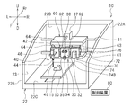
- FIG. 1 is a perspective view of a three-dimensional processing apparatus according to an embodiment.
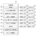
- FIG. 2 is a block diagram of a control device according to an embodiment.
- Drawing 3 is an explanatory view showing the state where a thermoplastic resin is discharged from a nozzle of a modeling head concerning one embodiment to a modeling table.
- FIG. 4 is an explanatory diagram illustrating a target three-dimensional structure that is theoretically formed based on the three-dimensional data.
- FIG. 5 is an explanatory view showing a three-dimensional structure actually formed based on the three-dimensional data.
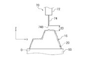
- FIG. 6 is an explanatory diagram illustrating a state before the scan head measures the surface shape of the three-dimensional structure.
- FIG. 1 is a perspective view of a three-dimensional processing apparatus according to an embodiment.
- FIG. 2 is a block diagram of a control device according to an embodiment.
- Drawing 3 is an explanatory view showing the state where a thermoplastic resin is discharged from a nozzle of a modeling head concerning one embodiment
- FIG. 7 is an explanatory diagram illustrating a state in which the scan head is measuring the surface shape of the three-dimensional structure.
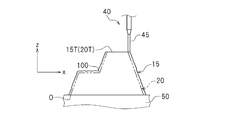
- FIG. 8 is an explanatory diagram illustrating a state before the processing head processes the surface of the three-dimensional structure.
- FIG. 9 is an explanatory diagram illustrating a state in which the processing head is processing the surface of the three-dimensional structure.
- FIG. 10 is an explanatory view showing a three-dimensional structure whose surface is processed by the processing head.
- FIG. 1 is a perspective view of a three-dimensional processing apparatus 10 according to the present embodiment.
- the three-dimensional processing apparatus 10 is an apparatus for modeling a three-dimensional structure.
- the three-dimensional processing apparatus 10 prepares a slice image representing the cross-sectional shape of the three-dimensional structure, cures the resin material, and sequentially laminates the cured resin layers having the cross-sectional shape along the slice image, thereby three-dimensional modeling. It is a device for modeling objects.
- the three-dimensional processing apparatus 10 is an apparatus that measures the surface shape of a three-dimensional modeled object.
- the three-dimensional processing apparatus 10 is an apparatus that processes the surface of a three-dimensional modeled object.
- the “cross-sectional shape” is a shape of a cross section when a three-dimensional structure is sliced for each predetermined thickness (for example, 0.1 mm).
- a thermoplastic resin is used as the resin material will be described as an example.
- left, right, top, and bottom mean left, right, top, and bottom, respectively, as viewed from an operator in front of the three-dimensional processing apparatus 10. Moreover, the direction which approaches the said operator from the three-dimensional processing apparatus 10 is made into the front, and the direction which leaves
- Reference numerals F, Rr, L, R, U, and D in the drawings represent front, rear, left, right, upper, and lower, respectively. However, these are only directions for convenience of explanation, and do not limit the installation mode of the three-dimensional processing apparatus 10 at all.
- the three-dimensional processing apparatus 10 includes a housing 22, a modeling head 30, a processing head 40, a modeling table 50, a control device 80, a carriage 60, and a scan head 70.
- the housing 22 includes a right side wall 22A, a left side wall 22B, a bottom wall 22C, and a rear wall 22D.
- An opening 23 is formed in the housing 22 from the upper side to the front side.
- the housing 22 is provided with a cover (not shown) that covers the opening 23.
- the carriage 60 is disposed in the housing 22.
- the carriage 60 is movably provided on a pair of first guide rails 61 disposed in the housing 22.
- the carriage 60 can move in the left-right direction along the first guide rail 61.
- the first guide rail 61 extending in the left-right direction is connected to the right side wall 22A and the left side wall 22B.
- the carriage 60 receives the driving force of the first motor 60A (see FIG. 2) and moves in the left-right direction.
- the first motor 60A is controlled by the control device 80.
- the carriage 60 includes a pair of second guide rails 62, a pair of third guide rails 63, and a pair of fourth guide rails 64.
- the second guide rail 62, the third guide rail 63, and the fourth guide rail 64 extend in the vertical direction.
- the second guide rail 62 is disposed on the left side of the third guide rail 63.
- the second guide rail 62 is disposed on the right side of the fourth guide rail 64.
- the modeling head 30 discharges the thermoplastic resin 38 based on the three-dimensional data of the three-dimensional structure to be modeled. As shown in FIG. 1, the modeling head 30 is disposed in the housing 22. The modeling head 30 is provided on the carriage 60. As the carriage 60 moves in the left-right direction, the modeling head 30 also moves in the left-right direction. The modeling head 30 is movably provided on the second guide rail 62. The modeling head 30 includes a main body 32, a nozzle 34 that discharges a thermoplastic resin 38, a heater 35, and a pair of roller gears 36. The main body 32 is movably provided on the second guide rail 62. The main body 32 moves in the vertical direction under the driving force of the second motor 30A (see FIG. 2).
- the modeling head 30 moves in the up-down direction.
- the second motor 30A is controlled by the control device 80.
- a cartridge 37 is disposed above the carriage 60.
- the cartridge 37 contains a thermoplastic resin 38.
- the cartridge 37 is replaceable.
- the nozzle 34 discharges the thermoplastic resin 38 conveyed from the cartridge 37 (see FIG. 1) to the modeling table 50.
- the nozzle diameter D of the nozzle 34 is configured to be changeable.
- the opening of the nozzle 34 is formed in a circular shape.
- the major axis of the opening is the nozzle diameter D.
- the heater 35 applies heat to the thermoplastic resin 38 conveyed from the cartridge 37.
- the heater 35 is attached to the main body 32.
- the heater 35 is disposed above the nozzle 34.
- the roller gear 36 is provided in the main body portion 32.
- the pair of roller gears 36 are arranged to be separated from each other.
- the roller gear 36 rotates upon receiving the driving force of the third motor 36A (see FIG. 2).
- the third motor 36A is controlled by the control device 80.
- the thermoplastic resin 38 conveyed from the cartridge 37 passes between the pair of roller gears 36.
- thermoplastic resin 38 As the roller gear 36 rotates, the thermoplastic resin 38 is conveyed to the nozzle 34 and discharged from the nozzle 34 to the modeling table 50.
- the thermoplastic resin 38 is softened by the heat of the heater 35, and is discharged from the nozzle 34 to the modeling table 50 in a soft state.
- the thermoplastic resin 38 discharged to the modeling table 50 is then cured.
- the modeling head 30 sequentially laminates a cured resin layer having a predetermined cross-sectional shape corresponding to the slice image created in the control device 80. Thereby, the desired three-dimensional structure 15 is modeled.
- the scan head 70 measures the surface shape of the three-dimensional structure 15 formed from the cured thermoplastic resin 38. As shown in FIG. 1, the scan head 70 is disposed in the housing 22. The scan head 70 is provided on the carriage 60. As the carriage 60 moves in the left-right direction, the scan head 70 also moves in the left-right direction. The scan head 70 is movably provided on the third guide rail 63. The scan head 70 is disposed on the right side of the modeling head 30. The scan head 70 moves integrally with the modeling head 30 and the processing head 40.
- the scan head 70 includes a main body 72 and a contact sensor 74. The main body 72 is movably provided on the third guide rail 63. The main body 72 moves in the vertical direction in response to the driving force of the fourth motor 70A (see FIG.
- the scan head 70 moves in the vertical direction.
- the fourth motor 70A is controlled by the control device 80.
- the contact sensor 74 is attached to the main body 72 so as to be movable in the vertical direction. A lower end 74 ⁇ / b> B of the contact sensor 74 is located below the main body 72. The movement of the contact sensor 74 is controlled by the control device 80.
- the contact sensor 74 moves downward from the main body 72 and contacts the three-dimensional structure 15. By repeating this, the surface shape of the three-dimensional structure 15 is measured.
- the scan head 70 can measure the surface shape at a predetermined point of the three-dimensional structure 15 by increasing the scan pitch (sample scan).
- the scan pitch may be, for example, not less than D and not more than 3D with respect to the nozzle diameter D.
- the thickness of the three-dimensional structure 15 obtained by laminating the resin hardened layer 15 to be cut in the processing step (the average value of the thickness to be cut, including surface irregularities).
- the degree of thickness variation and the maximum value are partially measured. From the result of the sample scan, the degree of cutting of the entire surface of the three-dimensional structure 15, that is, the approximate thickness of the cured resin layer to be cut and scraped, and the maximum thickness that can be generated in the entire three-dimensional structure 15 are obtained. presume.
- the initial position of the cutting edge at the start of cutting with respect to the surface of the three-dimensional structure 15 immediately after the formation can be set to the minimum distance, and the cutting time Can be shortened. That is, it is possible to save time by wobbling the machining head 40 in a space that does not require machining (a height equal to or greater than the maximum thickness of the three-dimensional structure 15).
- the variation in the thickness of the cured resin layer to be cut on the surface of the three-dimensional structure 15 immediately after the modeling is finished is It is known that it is almost the same level.
- the variation in the thickness in the planar portion of the three-dimensional structure 15 is substantially the same as a whole. Therefore, all the surface shapes of the three-dimensional structure 15 can be estimated by such a method by sample scanning.
- the scan head 70 may measure the entire surface shape of the three-dimensional structure 15 with a scan pitch smaller than D (full scan).
- the processing head 40 processes the surface of the three-dimensional structure 15 whose surface shape has been measured. As shown in FIG. 1, the processing head 40 is disposed in the housing 22. The processing head 40 is provided on the carriage 60. As the carriage 60 moves in the left-right direction, the processing head 40 also moves in the left-right direction. The processing head 40 is movably provided on the fourth guide rail 64. The processing head 40 is disposed on the left side of the modeling head 30. The processing head 40 moves integrally with the modeling head 30 and the scan head 70.
- the processing head 40 includes a main body 42, a spindle 44, a processing tool 45 detachably attached to the spindle 44, and a fifth motor 46 that rotates the spindle 44. The spindle 44 rotates the processing tool 45.
- the main body 42 is movably provided on the fourth guide rail 64.
- the main body portion 42 moves in the vertical direction under the driving force of the sixth motor 40A (see FIG. 2). Thereby, the process head 40 moves to an up-down direction.
- the sixth motor 40A is controlled by the control device 80.
- the spindle 44 is attached to the main body portion 42.
- the fifth motor 46 is attached to the main body 42.
- the fifth motor 46 is disposed above the spindle 44.
- the fifth motor 46 is controlled by the control device 80.
- the modeling table 50 holds the thermoplastic resin 38 discharged from the nozzle 34 of the modeling head 30.
- a three-dimensional structure 15 is formed on the modeling table 50.
- the formed three-dimensional structure 15 is positioned on the modeling table 50 until the measurement by the scan head 70 and the processing by the processing head 40 are completed.
- the modeling table 50 is disposed in the housing 22.
- the modeling table 50 is disposed below the modeling head 30, the processing head 40, and the scan head 70.
- the modeling table 50 is provided above the bottom wall 22C.
- the modeling table 50 is movably provided on a guide rail (not shown) provided on the bottom wall 22C.
- the modeling table 50 moves in the front-rear direction under the driving force of the seventh motor 50A (see FIG. 2).
- the seventh motor 50 ⁇ / b> A is controlled by the control device 80.
- the control device 80 controls the modeling of the three-dimensional structure 15, the measurement of the surface shape of the three-dimensional structure 15, and the processing of the surface of the three-dimensional structure 15. Specifically, the control device 80 controls the modeling head 30, the processing head 40, the modeling table 50, the carriage 60, the scan head 70, and the like. The control device 80 controls the modeling head 30, the processing head 40, and the scan head 70 based on the three-dimensional data of the three-dimensional structure to be modeled.
- the configuration of the control device 80 is not particularly limited.
- the control device 80 is a computer, and may include a central processing unit (hereinafter referred to as a CPU), a ROM storing a program executed by the CPU, a RAM, and the like.
- the three-dimensional data includes point cloud data, that is, three-dimensional coordinate data representing XYZ coordinate values, normal vectors of faces of triangles constituting the three-dimensional model, and coordinate values of three vertices of each triangle. It means recorded STL data.
- the control device 80 includes a storage unit 82, a slice image creation unit 84, a modeling path data creation unit 86, a modeling head control unit 88, a scanning path data creation unit 90, and a scan.
- a head control unit 92, a specifying unit 94, a machining path data creation unit 96, and a machining head control unit 98 are provided.
- the storage unit 82 stores 3D data of a 3D model to be modeled.
- FIG. 4 is a diagram illustrating an example of a three-dimensional structure (hereinafter, referred to as a target three-dimensional structure 20) that is theoretically formed based on the three-dimensional data stored in the storage unit 82.
- the storage unit 82 stores position information of the target three-dimensional structure 20.
- the position information of the target three-dimensional structure 20 is, for example, the origin information O of the target three-dimensional structure 20 and external information representing the surface shape of the target three-dimensional structure 20 based on the origin information O. And both.
- the position information of the target three-dimensional structure 20 is three-dimensional coordinate data based on the surface shape of the target three-dimensional structure 20.
- the storage unit 82 stores a plurality of slice images obtained by slicing the target three-dimensional structure 20 at predetermined intervals.
- the slice image is created by the slice image creation unit 84.
- the three-dimensional data is read into the storage unit 82 from a storage medium or another computer (not shown) by a user operation, for example.
- the slice image may be read into the storage unit 82 from a storage medium or another computer (not shown) by a user operation, for example.
- the slice image creation unit 84 slices the target three-dimensional structure 20 stored in the storage unit 82 in the vertical direction (Z-axis direction) at a predetermined interval, and slices corresponding to the cross-sectional shape of the target three-dimensional structure 20 Create multiple images.
- the target three-dimensional structure 20 is sliced parallel to the XY plane.
- the predetermined interval is, for example, not less than the nozzle diameter D.
- the modeling path data creation unit 86 creates modeling path data indicating the movement path of the modeling head 30 based on the created slice images.
- the created modeling path data is stored in the storage unit 82.
- the movement path of the modeling head 30 is a locus drawn by the lower end 34B of the nozzle 34.
- the modeling head control unit 88 controls the modeling head 30 to discharge the thermoplastic resin 38 to the modeling table 50 based on the three-dimensional data stored in the storage unit 82. That is, the modeling head control unit 88 controls the ejection of the thermoplastic resin 38 by the modeling head 30 and the movement of the modeling head 30 using the modeling path data.
- the modeling head control unit 88 controls the movement of the carriage 60 by driving the first motor 60A.
- the modeling head controller 88 controls the movement of the modeling head 30 by driving the second motor 30A.
- the modeling head control unit 88 controls the roller gear 36 by driving the third motor 36A.
- the modeling head control unit 88 controls the movement of the modeling table 50 by driving the seventh motor 50A.
- a three-dimensional structure is modeled on the modeling table 50.
- the target three-dimensional structure 20 is represented by a two-dot chain line.
- the scan path data creation unit 90 generates scan path data indicating the movement path of the scan head 70 with respect to the three-dimensional structure 15 formed on the modeling table 50 based on the three-dimensional data stored in the storage unit 82. create. As shown in FIG. 6, when the nozzle diameter of the nozzle 34 is D (see FIG. 3), the moving path of the scan head 70 is, for example, D to perpendicular to the surface of the target three-dimensional structure 20. The distance is about 3D. In the present embodiment, the moving path of the scan head 70 is separated by a distance of 2D in the vertical direction with respect to the surface of the target three-dimensional structure.
- the created scan path data is stored in the storage unit 82.
- the movement path of the scan head 70 is a locus drawn by the lower end 74B of the contact sensor 74.
- the contact sensor 74 moves downward from the main body 72 and contacts the three-dimensional structure 15.
- the measurement point can be arbitrarily set by the user.
- the scan head control unit 92 controls the scan head 70 to measure the surface shape of the three-dimensional structure 15 arranged on the modeling table 50 based on the three-dimensional data stored in the storage unit 82. That is, the scan head controller 92 controls the movement of the scan head 70 and the contact sensor 74 using the scan path data.
- the scan head controller 92 controls the movement of the carriage 60 by driving the first motor 60A.
- the scan head control unit 92 controls the movement of the scan head 70 by driving the fourth motor 70A.
- the scan head controller 92 drives the sixth motor 70A to control the movement of the modeling table 50.
- the scan head controller 92 controls the contact sensor 74 using an actuator (not shown).
- the surface shape of the three-dimensional structure 15 (that is, the three-dimensional coordinates of the three-dimensional structure 15) is measured.
- the scan head control unit 92 measures the surface shape at a predetermined point of the three-dimensional structure 15 arranged on the modeling table 50 (ie, sample scan) based on the three-dimensional data stored in the storage unit 82. In this way, the scan head 70 may be controlled. In this case, the scan head control unit 92 estimates the entire surface shape of the three-dimensional structure 15 based on the measured surface shape at the predetermined point.
- the specifying unit 94 is a surplus portion that is a difference between the surface shape of the three-dimensional structure 15 measured by the scan head 70 and the surface shape of the target three-dimensional structure 20. 100 is specified.
- the surplus portion 100 is a portion surrounded by the outline of the three-dimensional structure 15 and the outline of the target three-dimensional structure 20.
- the three-dimensional structure 15 is formed using the thermoplastic resin 38 (see FIG. 3)
- the three-dimensional structure 15 is formed larger than the target three-dimensional structure 20.
- the specifying unit 94 specifies the surplus portion 100 from the actually modeled three-dimensional model 15 and the target three-dimensional model 20.
- the specifying part 94 specifies the thickest part 102 having the largest thickness among the surplus parts 100.
- the thickest portion 102 is a portion of the surplus portion 100 that is thickest in the direction perpendicular to the surface of the target three-dimensional structure 20.
- the thickest portion 102 may be specified for each surface.
- Position information of the surplus portion 100 and the thickest portion 102 is stored in the storage unit 82.
- the processing path data creation unit 96 creates processing path data indicating the movement path of the processing head 40 with respect to the three-dimensional structure 15 formed on the modeling table 50 based on the position information of the surplus portion 100. For example, the processing path data creation unit 96 creates processing path data so that the thickest portion 102 is processed first.
- the created machining path data is stored in the storage unit 82.
- the movement path of the machining head 40 is a locus drawn by the lower end 45B (see FIG. 8) of the machining tool 45.
- the machining head control unit 98 controls the machining head 40 so as to cut the surplus portion 100. That is, the machining head control unit 98 controls machining of the surplus portion by the machining head 40 and movement of the machining head using the machining path data.
- the machining head controller 98 controls the movement of the carriage 60 by driving the first motor 60A.
- the machining head controller 98 drives the fifth motor 46 to control the rotation of the spindle 44.
- the machining head control unit 98 controls the movement of the machining head 40 by driving the sixth motor 40A.
- the machining head control unit 98 drives the seventh motor 50 ⁇ / b> A to control the movement of the modeling table 50. Thereby, the surface of the three-dimensional structure 15 is processed. Further, as shown in FIG.
- FIG. 9 is an explanatory diagram showing a state in which the surplus portion 100 including the thickest portion 102 (see FIG. 8) of the top surface 15T of the three-dimensional structure 15 has been scraped off.
- the upper surface 15T of the three-dimensional structure 15 substantially coincides with the upper surface 20T of the target three-dimensional structure 20.
- FIG. 10 is an explanatory diagram showing a state in which the surplus portion 100 (see FIG. 8) of the three-dimensional structure 15 has been removed.
- the shape of the three-dimensional structure 15 from which the surplus portion 100 has been cut off substantially matches the shape of the target three-dimensional structure 20.
- the three-dimensional structure 15 formed on the forming table 50 is measured by the scan head 70 and processed by the processing head 40 in the relative positions of the scan head 70 and the processing head 40. Since the relationship is specified by the three-dimensional processing apparatus 10 and the three-dimensional data of the three-dimensional structure to be used is common, it is not necessary to adjust the origin position during measurement and processing. Further, the scan head control unit 92 controls the scan head 70 so as to measure the surface shape of the three-dimensional structure 15 based on the three-dimensional data. Here, since it is possible to grasp in which part of the modeling table 50 the 3D model 15 is arranged by the three-dimensional data, the scan head 70 is placed in the vicinity of the three-dimensional model 15 before measuring the surface shape.
- the machining head control unit 98 controls the machining head 40 so as to cut the surplus portion 100 specified by the specifying unit 94. Since the specific part 94 makes it clear which part of the three-dimensional structure 15 should be cut, it is possible to move the machining head 40 to the surplus part 100 immediately for machining. Thereby, the total movement time of the processing head 40 can be significantly shortened.
- the time for discharging the thermoplastic resin 38 to form the three-dimensional structure 15 is longer than the time for processing the surface of the three-dimensional structure 15 by the processing head 40.
- the shape of the three-dimensional structure 15 can be reduced in this case. The accuracy will be slightly reduced.
- the present invention even if the amount of the thermoplastic resin 38 discharged from the modeling head 30 is increased per unit time and the three-dimensional structure 15 having a rough surface shape is formed, the three-dimensional structure is finally obtained. Since the surface 15 is processed, a high-quality three-dimensional structure 15 can be obtained. That is, the modeling time of the three-dimensional structure 15 can be shortened.
- the scan head control unit 92 measures the surface shape at a predetermined point of the three-dimensional structure 15 arranged on the modeling table 50 based on the three-dimensional data stored in the storage unit 82.
- the overall surface shape of the three-dimensional structure 15 can be estimated by controlling the scan head 70 and based on the measured surface shape at a predetermined point.
- the range of unevenness generated on the surface of the three-dimensional structure 15 immediately after being modeled from the thermoplastic resin 38 that is, immediately before processing by the processing head 40, or by the processing head 40 in the subsequent process.
- the measurement by the scan head 70 scans the entire three-dimensional structure 15 (that is, full scan). ) And scanning (ie, sample scanning) by specifying a predetermined number of scan points, and the surface shape of the entire three-dimensional structure 15 can be estimated from the result. Thereby, the total movement time of the scan head 70 can be significantly shortened.
- the machining head control unit 98 controls the machining head 40 so that the thickest part 102 is first cut.
- separate can be decreased more.
- the total movement time of the machining head 40 can be shortened.
- the machining head control unit 98 uses the machining path data created by the machining path data creation unit 96 to process the surplus portion 100 by the machining head 40 and the machining head. 40 movements are controlled. Thereby, the surplus part 100 of the shaped three-dimensional structure 15 can be shaved more reliably.
- the movement path of the scan head 70 is separated by 2D in the vertical direction with respect to the surface of the target three-dimensional structure 20.
- the surface shape of the three-dimensional structure 15 can be measured more quickly.
- the modeling head 30 is provided with a heater 35 that applies heat to the thermoplastic resin 38.
- the thermoplastic resin 38 is softened by the heater 35 and is cured on the modeling table 50 to form the three-dimensional model 15.
- the three-dimensional structure 15 that is shaped in this way may have irregularities on the surface, but according to the present embodiment, the surface of the three-dimensional structure 15 is scraped by the processing head 40, so that the surface has irregularities. A smooth and high-quality three-dimensional structure 15 can be obtained.
- the scan head 70 includes the contact sensor 74 that is a contact type sensor, but is not limited thereto.
- the scan head 70 may include a sensor that measures the surface shape of the three-dimensional structure without contact with laser light.
- the modeling head 30, the processing head 40, and the scan head 70 are provided in one carriage 60, but the present invention is not limited to this.
- the modeling head 30, the processing head 40, and the scan head 70 may be configured to move independently of each other.
- the positional relationship among the modeling head 30, the processing head 40, and the scan head 70 is not particularly limited.
- the order of the modeling head 30, the processing head 40, and the scan head 70 may be switched.
Landscapes
- Engineering & Computer Science (AREA)
- Chemical & Material Sciences (AREA)
- Materials Engineering (AREA)
- Manufacturing & Machinery (AREA)
- Mechanical Engineering (AREA)
- Physics & Mathematics (AREA)
- Optics & Photonics (AREA)
Abstract
Description
15 三次元造形物
20 目的三次元造形物
30 造形ヘッド
38 熱可塑性樹脂
40 加工ヘッド
50 造形テーブル
70 スキャンヘッド
80 制御装置
88 造形ヘッド制御部
92 スキャンヘッド制御部
94 特定部
98 加工ヘッド制御部
100 余剰部分
102 最厚部
Claims (6)
- 造形する三次元造形物の三次元データに基づいて樹脂材料を吐出する造形ヘッドと、
前記造形ヘッドから吐出された前記樹脂材料を保持する造形テーブルと、
前記造形テーブルに配置されかつ前記樹脂材料から造形された三次元造形物の表面形状を測定するスキャンヘッドと、
前記造形テーブルに配置されかつ前記測定された三次元造形物の表面を加工する加工ヘッドと、
前記造形ヘッドと、前記スキャンヘッドと、前記加工ヘッドとを制御する制御装置と、を備え、
前記制御装置は、
前記三次元データに基づいて、前記造形テーブルに前記樹脂材料を吐出するように前記造形ヘッドを制御する造形ヘッド制御部と、
前記三次元データに基づいて、前記造形テーブルに配置された前記三次元造形物の表面形状を測定するように前記スキャンヘッドを制御するスキャンヘッド制御部と、
前記スキャンヘッドによって測定された前記三次元造形物の表面形状と、前記三次元データに基づいて理論的に造形される三次元造形物の表面形状との差分である余剰部分を特定する特定部と、
前記余剰部分を削るように前記加工ヘッドを制御する加工ヘッド制御部と、を備えている、三次元加工装置。 - 前記スキャンヘッド制御部は、前記三次元データに基づいて、前記造形テーブルに配置された前記三次元造形物の所定のポイントにおける表面形状を測定するように前記スキャンヘッドを制御し、かつ、測定された前記所定のポイントにおける表面形状に基づいて、前記三次元造形物の全体の表面形状を推定する、請求項1に記載の三次元加工装置。
- 前記特定部は、前記余剰部分のうち最も厚みの厚い最厚部を特定し、
前記加工ヘッド制御部は、前記最厚部を最初に削るように前記加工ヘッドを制御する、請求項1または2に記載の三次元加工装置。 - 前記制御装置は、前記余剰部分の位置情報に基づいて、前記造形された三次元造形物に対する前記加工ヘッドの移動経路を示す加工用パスデータを作成する加工用パスデータ作成部をさらに備え、
前記加工ヘッド制御部は、前記加工用パスデータを用いて、前記加工ヘッドによる前記余剰部分の加工および前記加工ヘッドの移動を制御する、請求項1から3のいずれか一項に記載の三次元加工装置。 - 前記制御装置は、前記三次元データに基づいて、前記造形された三次元造形物に対する前記スキャンヘッドの移動経路を示すスキャン用パスデータを作成するスキャン用パスデータ作成部をさらに備え、
前記造形ヘッドは、前記樹脂材料を吐出するノズルを備え、
前記ノズルのノズル径をDとしたとき、前記スキャンヘッドの移動経路は、前記三次元データに基づいて理論的に造形される三次元造形物の表面に対して垂直方向にD~3Dの距離だけ離れている、請求項1から4のいずれか一項に記載の三次元加工装置。 - 前記樹脂材料は、熱可塑性樹脂であり、
前記造形ヘッドには、前記熱可塑性樹脂に熱を加えるヒータが設けられている、請求項1から5のいずれか一項に記載の三次元加工装置。
Priority Applications (2)
| Application Number | Priority Date | Filing Date | Title |
|---|---|---|---|
| JP2017557817A JP6560363B2 (ja) | 2015-12-22 | 2016-11-28 | 三次元加工装置 |
| US16/064,534 US20180290387A1 (en) | 2015-12-22 | 2016-11-28 | Three-dimensional processing device |
Applications Claiming Priority (2)
| Application Number | Priority Date | Filing Date | Title |
|---|---|---|---|
| JP2015249524 | 2015-12-22 | ||
| JP2015-249524 | 2015-12-22 |
Publications (1)
| Publication Number | Publication Date |
|---|---|
| WO2017110375A1 true WO2017110375A1 (ja) | 2017-06-29 |
Family
ID=59090632
Family Applications (1)
| Application Number | Title | Priority Date | Filing Date |
|---|---|---|---|
| PCT/JP2016/085201 WO2017110375A1 (ja) | 2015-12-22 | 2016-11-28 | 三次元加工装置 |
Country Status (3)
| Country | Link |
|---|---|
| US (1) | US20180290387A1 (ja) |
| JP (1) | JP6560363B2 (ja) |
| WO (1) | WO2017110375A1 (ja) |
Cited By (4)
| Publication number | Priority date | Publication date | Assignee | Title |
|---|---|---|---|---|
| EP3473441A1 (en) * | 2017-10-23 | 2019-04-24 | General Electric Company | Moveable molding assembly for use with additive manufacturing |
| EP3608082A1 (de) * | 2018-08-08 | 2020-02-12 | Homag Bohrsysteme GmbH | Verfahren zum bearbeiten von werkstücken |
| EP3834985B1 (en) | 2019-12-13 | 2022-07-20 | C.M.S. S.p.A. | Machining centre and method for machining workpieces |
| US11794407B2 (en) | 2020-01-31 | 2023-10-24 | Seiko Epson Corporation | Method for producing three-dimensional shaped article using applied reheating and secondary shaping steps |
Families Citing this family (5)
| Publication number | Priority date | Publication date | Assignee | Title |
|---|---|---|---|---|
| CN109228336A (zh) * | 2018-10-31 | 2019-01-18 | 武汉科技大学 | 一种五轴增减材复合加工装置 |
| KR102352274B1 (ko) * | 2020-03-24 | 2022-01-18 | 창원대학교 산학협력단 | 밀링 가공이 가능한 3d 프린터 |
| DE102020118979A1 (de) * | 2020-07-17 | 2022-01-20 | Hans Weber Maschinenfabrik Gmbh | Vorrichtung zur extrusionsbasierten Herstellung wenigstens eines dreidimensionalen Objekts |
| CN113021901B (zh) * | 2021-04-29 | 2022-11-25 | 渭南职业技术学院 | 一种具有无线传输功能的安全可靠型3d打印机 |
| CN113771036B (zh) * | 2021-09-24 | 2023-03-28 | 三一建筑机器人(西安)研究院有限公司 | 一种切割方法、装置及切割设备 |
Citations (4)
| Publication number | Priority date | Publication date | Assignee | Title |
|---|---|---|---|---|
| WO1997024217A1 (en) * | 1995-12-31 | 1997-07-10 | Shinko Sellbic Co., Ltd. | Moldless molding method using no mold and apparatus therefor |
| JP2000073108A (ja) * | 1998-08-26 | 2000-03-07 | Matsushita Electric Works Ltd | 金属粉末焼結部品の表面仕上げ方法 |
| JP2015196264A (ja) * | 2014-03-31 | 2015-11-09 | 三菱重工業株式会社 | 三次元積層装置及び三次元積層方法 |
| JP2015223753A (ja) * | 2014-05-27 | 2015-12-14 | 株式会社Ihi | 三次元造形装置及び三次元造形方法 |
Family Cites Families (5)
| Publication number | Priority date | Publication date | Assignee | Title |
|---|---|---|---|---|
| US9421716B2 (en) * | 2012-08-08 | 2016-08-23 | Makerbot Industries, Llc | Photo booth for three-dimensional images |
| US20150056317A1 (en) * | 2013-08-23 | 2015-02-26 | Xyzprinting, Inc. | Three-dimensional printing apparatus |
| DE102013217422A1 (de) * | 2013-09-02 | 2015-03-05 | Carl Zeiss Industrielle Messtechnik Gmbh | Koordinatenmessgerät und Verfahren zur Vermessung und mindestens teilweisen Erzeugung eines Werkstücks |
| JP2015112836A (ja) * | 2013-12-13 | 2015-06-22 | コニカミノルタ株式会社 | 三次元造形装置および三次元造形方法 |
| CN104015356A (zh) * | 2014-05-29 | 2014-09-03 | 北京中科博益科技有限公司 | 一种集成有后续加工功能的3d打印设备 |
-
2016
- 2016-11-28 JP JP2017557817A patent/JP6560363B2/ja active Active
- 2016-11-28 WO PCT/JP2016/085201 patent/WO2017110375A1/ja active Application Filing
- 2016-11-28 US US16/064,534 patent/US20180290387A1/en not_active Abandoned
Patent Citations (4)
| Publication number | Priority date | Publication date | Assignee | Title |
|---|---|---|---|---|
| WO1997024217A1 (en) * | 1995-12-31 | 1997-07-10 | Shinko Sellbic Co., Ltd. | Moldless molding method using no mold and apparatus therefor |
| JP2000073108A (ja) * | 1998-08-26 | 2000-03-07 | Matsushita Electric Works Ltd | 金属粉末焼結部品の表面仕上げ方法 |
| JP2015196264A (ja) * | 2014-03-31 | 2015-11-09 | 三菱重工業株式会社 | 三次元積層装置及び三次元積層方法 |
| JP2015223753A (ja) * | 2014-05-27 | 2015-12-14 | 株式会社Ihi | 三次元造形装置及び三次元造形方法 |
Cited By (5)
| Publication number | Priority date | Publication date | Assignee | Title |
|---|---|---|---|---|
| EP3473441A1 (en) * | 2017-10-23 | 2019-04-24 | General Electric Company | Moveable molding assembly for use with additive manufacturing |
| EP3608082A1 (de) * | 2018-08-08 | 2020-02-12 | Homag Bohrsysteme GmbH | Verfahren zum bearbeiten von werkstücken |
| EP3834985B1 (en) | 2019-12-13 | 2022-07-20 | C.M.S. S.p.A. | Machining centre and method for machining workpieces |
| US11794407B2 (en) | 2020-01-31 | 2023-10-24 | Seiko Epson Corporation | Method for producing three-dimensional shaped article using applied reheating and secondary shaping steps |
| JP7388212B2 (ja) | 2020-01-31 | 2023-11-29 | セイコーエプソン株式会社 | 三次元造形物の製造方法および三次元造形装置 |
Also Published As
| Publication number | Publication date |
|---|---|
| JPWO2017110375A1 (ja) | 2018-07-26 |
| JP6560363B2 (ja) | 2019-08-14 |
| US20180290387A1 (en) | 2018-10-11 |
Similar Documents
| Publication | Publication Date | Title |
|---|---|---|
| JP6560363B2 (ja) | 三次元加工装置 | |
| US20200156361A1 (en) | Dynamic layer selection in additive manufacturing using sensor feedback | |
| US9573323B2 (en) | Method for generating and building support structures with deposition-based digital manufacturing systems | |
| CN104493493A (zh) | 多轴铣削加工及激光熔融复合3d打印设备 | |
| US9718239B2 (en) | Three dimensional printing apparatus and three dimensional printing method | |
| JP2016078392A (ja) | 積層造形装置 | |
| CN105643943A (zh) | 一种增材制造用支撑的生成方法及其系统 | |
| CN204524788U (zh) | 多轴铣削加工及激光熔融复合3d打印设备 | |
| CN104476196A (zh) | 激光熔融及激光铣削复合3d打印设备 | |
| JP3687677B1 (ja) | 光造形方法と光造形システム並びに光造形用プログラム | |
| KR20180099788A (ko) | 삼차원 형상 조형물의 제조 방법 | |
| Lemu | Study of capabilities and limitations of 3D printing technology | |
| KR101692141B1 (ko) | 삼차원 구조물 제조장치 및 방법 | |
| CN117255726A (zh) | 加工系统 | |
| JP7197437B2 (ja) | 積層造形物の積層計画方法、積層造形物の製造方法及び製造装置 | |
| KR20150098340A (ko) | 오토레벨러 및 모재 냉각부가 구비되는 노즐유닛 | |
| JP2019025759A (ja) | 造形装置、造形方法、及び造形制御プログラム | |
| JP2018065366A (ja) | レーザーを用いた3dプリンタの走査軌跡範囲を設定する方法 | |
| KR20180092970A (ko) | 3차원의 금속성 성형 바디를 제작하기 위한 장치 및 방법 | |
| JP2020006679A (ja) | インクジェット幅調整方法および3d印刷設備 | |
| JP4141379B2 (ja) | 三次元物体の造形方法および造形装置 | |
| KR101989123B1 (ko) | 동작지령 검증방법, 가공장치의 제어방법, 동작지령 검증프로그램을 기록한 기록매체 및 동작지령 검증시스템 | |
| JP4639133B2 (ja) | 三次元造形方法 | |
| KR101561111B1 (ko) | 입체 조형물 연마를 수행하는 3차원 프린터 및 3차원 프린터의 연마 방법 | |
| JP6692944B2 (ja) | 3dプリンティング方法及び3dプリンティング装置 |
Legal Events
| Date | Code | Title | Description |
|---|---|---|---|
| 121 | Ep: the epo has been informed by wipo that ep was designated in this application |
Ref document number: 16878269 Country of ref document: EP Kind code of ref document: A1 |
|
| ENP | Entry into the national phase |
Ref document number: 2017557817 Country of ref document: JP Kind code of ref document: A |
|
| WWE | Wipo information: entry into national phase |
Ref document number: 16064534 Country of ref document: US |
|
| NENP | Non-entry into the national phase |
Ref country code: DE |
|
| 122 | Ep: pct application non-entry in european phase |
Ref document number: 16878269 Country of ref document: EP Kind code of ref document: A1 |