WO2017104479A1 - 熱硬化性接着シート、補強部付フレキシブルプリント配線板、その製造方法及び電子機器 - Google Patents
熱硬化性接着シート、補強部付フレキシブルプリント配線板、その製造方法及び電子機器 Download PDFInfo
- Publication number
- WO2017104479A1 WO2017104479A1 PCT/JP2016/086166 JP2016086166W WO2017104479A1 WO 2017104479 A1 WO2017104479 A1 WO 2017104479A1 JP 2016086166 W JP2016086166 W JP 2016086166W WO 2017104479 A1 WO2017104479 A1 WO 2017104479A1
- Authority
- WO
- WIPO (PCT)
- Prior art keywords
- thermosetting adhesive
- adhesive sheet
- wiring board
- thermosetting
- flexible printed
- Prior art date
- Legal status (The legal status is an assumption and is not a legal conclusion. Google has not performed a legal analysis and makes no representation as to the accuracy of the status listed.)
- Ceased
Links
Classifications
-
- H—ELECTRICITY
- H05—ELECTRIC TECHNIQUES NOT OTHERWISE PROVIDED FOR
- H05K—PRINTED CIRCUITS; CASINGS OR CONSTRUCTIONAL DETAILS OF ELECTRIC APPARATUS; MANUFACTURE OF ASSEMBLAGES OF ELECTRICAL COMPONENTS
- H05K3/00—Apparatus or processes for manufacturing printed circuits
- H05K3/38—Improvement of the adhesion between the insulating substrate and the metal
- H05K3/386—Improvement of the adhesion between the insulating substrate and the metal by the use of an organic polymeric bonding layer, e.g. adhesive
-
- C—CHEMISTRY; METALLURGY
- C09—DYES; PAINTS; POLISHES; NATURAL RESINS; ADHESIVES; COMPOSITIONS NOT OTHERWISE PROVIDED FOR; APPLICATIONS OF MATERIALS NOT OTHERWISE PROVIDED FOR
- C09J—ADHESIVES; NON-MECHANICAL ASPECTS OF ADHESIVE PROCESSES IN GENERAL; ADHESIVE PROCESSES NOT PROVIDED FOR ELSEWHERE; USE OF MATERIALS AS ADHESIVES
- C09J11/00—Features of adhesives not provided for in group C09J9/00, e.g. additives
- C09J11/02—Non-macromolecular additives
- C09J11/04—Non-macromolecular additives inorganic
-
- C—CHEMISTRY; METALLURGY
- C09—DYES; PAINTS; POLISHES; NATURAL RESINS; ADHESIVES; COMPOSITIONS NOT OTHERWISE PROVIDED FOR; APPLICATIONS OF MATERIALS NOT OTHERWISE PROVIDED FOR
- C09J—ADHESIVES; NON-MECHANICAL ASPECTS OF ADHESIVE PROCESSES IN GENERAL; ADHESIVE PROCESSES NOT PROVIDED FOR ELSEWHERE; USE OF MATERIALS AS ADHESIVES
- C09J201/00—Adhesives based on unspecified macromolecular compounds
-
- C—CHEMISTRY; METALLURGY
- C09—DYES; PAINTS; POLISHES; NATURAL RESINS; ADHESIVES; COMPOSITIONS NOT OTHERWISE PROVIDED FOR; APPLICATIONS OF MATERIALS NOT OTHERWISE PROVIDED FOR
- C09J—ADHESIVES; NON-MECHANICAL ASPECTS OF ADHESIVE PROCESSES IN GENERAL; ADHESIVE PROCESSES NOT PROVIDED FOR ELSEWHERE; USE OF MATERIALS AS ADHESIVES
- C09J5/00—Adhesive processes in general; Adhesive processes not provided for elsewhere, e.g. relating to primers
- C09J5/06—Adhesive processes in general; Adhesive processes not provided for elsewhere, e.g. relating to primers involving heating of the applied adhesive
-
- C—CHEMISTRY; METALLURGY
- C09—DYES; PAINTS; POLISHES; NATURAL RESINS; ADHESIVES; COMPOSITIONS NOT OTHERWISE PROVIDED FOR; APPLICATIONS OF MATERIALS NOT OTHERWISE PROVIDED FOR
- C09J—ADHESIVES; NON-MECHANICAL ASPECTS OF ADHESIVE PROCESSES IN GENERAL; ADHESIVE PROCESSES NOT PROVIDED FOR ELSEWHERE; USE OF MATERIALS AS ADHESIVES
- C09J7/00—Adhesives in the form of films or foils
- C09J7/20—Adhesives in the form of films or foils characterised by their carriers
- C09J7/205—Adhesives in the form of films or foils characterised by their carriers characterised by the backing impregnating composition
-
- C—CHEMISTRY; METALLURGY
- C09—DYES; PAINTS; POLISHES; NATURAL RESINS; ADHESIVES; COMPOSITIONS NOT OTHERWISE PROVIDED FOR; APPLICATIONS OF MATERIALS NOT OTHERWISE PROVIDED FOR
- C09J—ADHESIVES; NON-MECHANICAL ASPECTS OF ADHESIVE PROCESSES IN GENERAL; ADHESIVE PROCESSES NOT PROVIDED FOR ELSEWHERE; USE OF MATERIALS AS ADHESIVES
- C09J7/00—Adhesives in the form of films or foils
- C09J7/20—Adhesives in the form of films or foils characterised by their carriers
- C09J7/21—Paper; Textile fabrics
-
- C—CHEMISTRY; METALLURGY
- C09—DYES; PAINTS; POLISHES; NATURAL RESINS; ADHESIVES; COMPOSITIONS NOT OTHERWISE PROVIDED FOR; APPLICATIONS OF MATERIALS NOT OTHERWISE PROVIDED FOR
- C09J—ADHESIVES; NON-MECHANICAL ASPECTS OF ADHESIVE PROCESSES IN GENERAL; ADHESIVE PROCESSES NOT PROVIDED FOR ELSEWHERE; USE OF MATERIALS AS ADHESIVES
- C09J7/00—Adhesives in the form of films or foils
- C09J7/20—Adhesives in the form of films or foils characterised by their carriers
- C09J7/22—Plastics; Metallised plastics
- C09J7/25—Plastics; Metallised plastics based on macromolecular compounds obtained otherwise than by reactions involving only carbon-to-carbon unsaturated bonds
- C09J7/255—Polyesters
-
- C—CHEMISTRY; METALLURGY
- C09—DYES; PAINTS; POLISHES; NATURAL RESINS; ADHESIVES; COMPOSITIONS NOT OTHERWISE PROVIDED FOR; APPLICATIONS OF MATERIALS NOT OTHERWISE PROVIDED FOR
- C09J—ADHESIVES; NON-MECHANICAL ASPECTS OF ADHESIVE PROCESSES IN GENERAL; ADHESIVE PROCESSES NOT PROVIDED FOR ELSEWHERE; USE OF MATERIALS AS ADHESIVES
- C09J7/00—Adhesives in the form of films or foils
- C09J7/20—Adhesives in the form of films or foils characterised by their carriers
- C09J7/28—Metal sheet
-
- C—CHEMISTRY; METALLURGY
- C09—DYES; PAINTS; POLISHES; NATURAL RESINS; ADHESIVES; COMPOSITIONS NOT OTHERWISE PROVIDED FOR; APPLICATIONS OF MATERIALS NOT OTHERWISE PROVIDED FOR
- C09J—ADHESIVES; NON-MECHANICAL ASPECTS OF ADHESIVE PROCESSES IN GENERAL; ADHESIVE PROCESSES NOT PROVIDED FOR ELSEWHERE; USE OF MATERIALS AS ADHESIVES
- C09J7/00—Adhesives in the form of films or foils
- C09J7/30—Adhesives in the form of films or foils characterised by the adhesive composition
- C09J7/35—Heat-activated
-
- C—CHEMISTRY; METALLURGY
- C09—DYES; PAINTS; POLISHES; NATURAL RESINS; ADHESIVES; COMPOSITIONS NOT OTHERWISE PROVIDED FOR; APPLICATIONS OF MATERIALS NOT OTHERWISE PROVIDED FOR
- C09J—ADHESIVES; NON-MECHANICAL ASPECTS OF ADHESIVE PROCESSES IN GENERAL; ADHESIVE PROCESSES NOT PROVIDED FOR ELSEWHERE; USE OF MATERIALS AS ADHESIVES
- C09J9/00—Adhesives characterised by their physical nature or the effects produced, e.g. glue sticks
- C09J9/02—Electrically-conducting adhesives
-
- H—ELECTRICITY
- H05—ELECTRIC TECHNIQUES NOT OTHERWISE PROVIDED FOR
- H05K—PRINTED CIRCUITS; CASINGS OR CONSTRUCTIONAL DETAILS OF ELECTRIC APPARATUS; MANUFACTURE OF ASSEMBLAGES OF ELECTRICAL COMPONENTS
- H05K1/00—Printed circuits
- H05K1/02—Details
- H05K1/0277—Bendability or stretchability details
- H05K1/028—Bending or folding regions of flexible printed circuits
-
- H—ELECTRICITY
- H05—ELECTRIC TECHNIQUES NOT OTHERWISE PROVIDED FOR
- H05K—PRINTED CIRCUITS; CASINGS OR CONSTRUCTIONAL DETAILS OF ELECTRIC APPARATUS; MANUFACTURE OF ASSEMBLAGES OF ELECTRICAL COMPONENTS
- H05K1/00—Printed circuits
- H05K1/02—Details
- H05K1/0277—Bendability or stretchability details
- H05K1/028—Bending or folding regions of flexible printed circuits
- H05K1/0281—Reinforcement details thereof
-
- H—ELECTRICITY
- H05—ELECTRIC TECHNIQUES NOT OTHERWISE PROVIDED FOR
- H05K—PRINTED CIRCUITS; CASINGS OR CONSTRUCTIONAL DETAILS OF ELECTRIC APPARATUS; MANUFACTURE OF ASSEMBLAGES OF ELECTRICAL COMPONENTS
- H05K3/00—Apparatus or processes for manufacturing printed circuits
- H05K3/46—Manufacturing multilayer circuits
- H05K3/4644—Manufacturing multilayer circuits by building the multilayer layer by layer, i.e. build-up multilayer circuits
-
- C—CHEMISTRY; METALLURGY
- C08—ORGANIC MACROMOLECULAR COMPOUNDS; THEIR PREPARATION OR CHEMICAL WORKING-UP; COMPOSITIONS BASED THEREON
- C08K—Use of inorganic or non-macromolecular organic substances as compounding ingredients
- C08K2201/00—Specific properties of additives
- C08K2201/001—Conductive additives
-
- C—CHEMISTRY; METALLURGY
- C09—DYES; PAINTS; POLISHES; NATURAL RESINS; ADHESIVES; COMPOSITIONS NOT OTHERWISE PROVIDED FOR; APPLICATIONS OF MATERIALS NOT OTHERWISE PROVIDED FOR
- C09J—ADHESIVES; NON-MECHANICAL ASPECTS OF ADHESIVE PROCESSES IN GENERAL; ADHESIVE PROCESSES NOT PROVIDED FOR ELSEWHERE; USE OF MATERIALS AS ADHESIVES
- C09J2203/00—Applications of adhesives in processes or use of adhesives in the form of films or foils
- C09J2203/326—Applications of adhesives in processes or use of adhesives in the form of films or foils for bonding electronic components such as wafers, chips or semiconductors
-
- C—CHEMISTRY; METALLURGY
- C09—DYES; PAINTS; POLISHES; NATURAL RESINS; ADHESIVES; COMPOSITIONS NOT OTHERWISE PROVIDED FOR; APPLICATIONS OF MATERIALS NOT OTHERWISE PROVIDED FOR
- C09J—ADHESIVES; NON-MECHANICAL ASPECTS OF ADHESIVE PROCESSES IN GENERAL; ADHESIVE PROCESSES NOT PROVIDED FOR ELSEWHERE; USE OF MATERIALS AS ADHESIVES
- C09J2301/00—Additional features of adhesives in the form of films or foils
- C09J2301/30—Additional features of adhesives in the form of films or foils characterized by the chemical, physicochemical or physical properties of the adhesive or the carrier
- C09J2301/314—Additional features of adhesives in the form of films or foils characterized by the chemical, physicochemical or physical properties of the adhesive or the carrier the adhesive layer and/or the carrier being conductive
-
- C—CHEMISTRY; METALLURGY
- C09—DYES; PAINTS; POLISHES; NATURAL RESINS; ADHESIVES; COMPOSITIONS NOT OTHERWISE PROVIDED FOR; APPLICATIONS OF MATERIALS NOT OTHERWISE PROVIDED FOR
- C09J—ADHESIVES; NON-MECHANICAL ASPECTS OF ADHESIVE PROCESSES IN GENERAL; ADHESIVE PROCESSES NOT PROVIDED FOR ELSEWHERE; USE OF MATERIALS AS ADHESIVES
- C09J2301/00—Additional features of adhesives in the form of films or foils
- C09J2301/40—Additional features of adhesives in the form of films or foils characterized by the presence of essential components
- C09J2301/408—Additional features of adhesives in the form of films or foils characterized by the presence of essential components additives as essential feature of the adhesive layer
-
- C—CHEMISTRY; METALLURGY
- C09—DYES; PAINTS; POLISHES; NATURAL RESINS; ADHESIVES; COMPOSITIONS NOT OTHERWISE PROVIDED FOR; APPLICATIONS OF MATERIALS NOT OTHERWISE PROVIDED FOR
- C09J—ADHESIVES; NON-MECHANICAL ASPECTS OF ADHESIVE PROCESSES IN GENERAL; ADHESIVE PROCESSES NOT PROVIDED FOR ELSEWHERE; USE OF MATERIALS AS ADHESIVES
- C09J2301/00—Additional features of adhesives in the form of films or foils
- C09J2301/40—Additional features of adhesives in the form of films or foils characterized by the presence of essential components
- C09J2301/41—Additional features of adhesives in the form of films or foils characterized by the presence of essential components additives as essential feature of the carrier layer
-
- C—CHEMISTRY; METALLURGY
- C09—DYES; PAINTS; POLISHES; NATURAL RESINS; ADHESIVES; COMPOSITIONS NOT OTHERWISE PROVIDED FOR; APPLICATIONS OF MATERIALS NOT OTHERWISE PROVIDED FOR
- C09J—ADHESIVES; NON-MECHANICAL ASPECTS OF ADHESIVE PROCESSES IN GENERAL; ADHESIVE PROCESSES NOT PROVIDED FOR ELSEWHERE; USE OF MATERIALS AS ADHESIVES
- C09J2400/00—Presence of inorganic and organic materials
- C09J2400/10—Presence of inorganic materials
- C09J2400/16—Metal
-
- C—CHEMISTRY; METALLURGY
- C09—DYES; PAINTS; POLISHES; NATURAL RESINS; ADHESIVES; COMPOSITIONS NOT OTHERWISE PROVIDED FOR; APPLICATIONS OF MATERIALS NOT OTHERWISE PROVIDED FOR
- C09J—ADHESIVES; NON-MECHANICAL ASPECTS OF ADHESIVE PROCESSES IN GENERAL; ADHESIVE PROCESSES NOT PROVIDED FOR ELSEWHERE; USE OF MATERIALS AS ADHESIVES
- C09J2400/00—Presence of inorganic and organic materials
- C09J2400/10—Presence of inorganic materials
- C09J2400/16—Metal
- C09J2400/163—Metal in the substrate
-
- C—CHEMISTRY; METALLURGY
- C09—DYES; PAINTS; POLISHES; NATURAL RESINS; ADHESIVES; COMPOSITIONS NOT OTHERWISE PROVIDED FOR; APPLICATIONS OF MATERIALS NOT OTHERWISE PROVIDED FOR
- C09J—ADHESIVES; NON-MECHANICAL ASPECTS OF ADHESIVE PROCESSES IN GENERAL; ADHESIVE PROCESSES NOT PROVIDED FOR ELSEWHERE; USE OF MATERIALS AS ADHESIVES
- C09J2463/00—Presence of epoxy resin
-
- C—CHEMISTRY; METALLURGY
- C09—DYES; PAINTS; POLISHES; NATURAL RESINS; ADHESIVES; COMPOSITIONS NOT OTHERWISE PROVIDED FOR; APPLICATIONS OF MATERIALS NOT OTHERWISE PROVIDED FOR
- C09J—ADHESIVES; NON-MECHANICAL ASPECTS OF ADHESIVE PROCESSES IN GENERAL; ADHESIVE PROCESSES NOT PROVIDED FOR ELSEWHERE; USE OF MATERIALS AS ADHESIVES
- C09J2467/00—Presence of polyester
- C09J2467/005—Presence of polyester in the release coating
-
- C—CHEMISTRY; METALLURGY
- C09—DYES; PAINTS; POLISHES; NATURAL RESINS; ADHESIVES; COMPOSITIONS NOT OTHERWISE PROVIDED FOR; APPLICATIONS OF MATERIALS NOT OTHERWISE PROVIDED FOR
- C09J—ADHESIVES; NON-MECHANICAL ASPECTS OF ADHESIVE PROCESSES IN GENERAL; ADHESIVE PROCESSES NOT PROVIDED FOR ELSEWHERE; USE OF MATERIALS AS ADHESIVES
- C09J2467/00—Presence of polyester
- C09J2467/006—Presence of polyester in the substrate
-
- H—ELECTRICITY
- H05—ELECTRIC TECHNIQUES NOT OTHERWISE PROVIDED FOR
- H05K—PRINTED CIRCUITS; CASINGS OR CONSTRUCTIONAL DETAILS OF ELECTRIC APPARATUS; MANUFACTURE OF ASSEMBLAGES OF ELECTRICAL COMPONENTS
- H05K2203/00—Indexing scheme relating to apparatus or processes for manufacturing printed circuits covered by H05K3/00
- H05K2203/11—Treatments characterised by their effect, e.g. heating, cooling, roughening
- H05K2203/1105—Heating or thermal processing not related to soldering, firing, curing or laminating, e.g. for shaping the substrate or during finish plating
-
- H—ELECTRICITY
- H05—ELECTRIC TECHNIQUES NOT OTHERWISE PROVIDED FOR
- H05K—PRINTED CIRCUITS; CASINGS OR CONSTRUCTIONAL DETAILS OF ELECTRIC APPARATUS; MANUFACTURE OF ASSEMBLAGES OF ELECTRICAL COMPONENTS
- H05K3/00—Apparatus or processes for manufacturing printed circuits
- H05K3/0058—Laminating printed circuit boards onto other substrates, e.g. metallic substrates
Definitions
- the present invention relates to a thermosetting adhesive sheet that can be used for forming a reinforcing portion provided to prevent a component mounted on a flexible printed wiring board from falling off.
- the flexible printed wiring board one having a configuration in which a ground circuit formed of copper or the like on the surface of a polyimide film or the like and a component such as a connector is mounted on a part of the circuit is generally known.
- the flexible printed wiring board usually has a thickness of 50 ⁇ m on the back surface with respect to the mounting surface for the purpose of preventing connection failure when mounting the component and preventing the component from falling off over time.
- a metal reinforcing plate such as a stainless plate is pasted with a conductive adhesive or the like (see, for example, Patent Document 1).
- the thick-film reinforcing plate when the thick-film reinforcing plate is provided, the flexible printed wiring board and the electronic device on which the flexible printed wiring board is mounted are inevitably thickened, so that there are cases where it cannot contribute to the thinning of the electronic device and the like required by the industry.
- the flexible printed wiring board is contracted when the conductive adhesive is cured.
- Warping
- the flexible printed wiring board is known to electrically connect the ground circuit and other members using a conductive adhesive tape in order to prevent the occurrence of noise due to the influence of electromagnetic waves.
- Patent Document 1 Japanese Patent Document 1
- the problem to be solved by the present invention is to provide a flexible printed wiring board to a level capable of preventing the mounting component from falling off without using a thick metal reinforcing plate which is a cause of thickening of electronic devices and the like. It is possible to provide a thermosetting adhesive sheet that can suppress warpage when heat-cured and has good conductivity.
- thermosetting adhesive sheet used for reinforcing a flexible printed wiring board, wherein the thermosetting adhesive sheet is heated on at least one side of a woven fabric, a non-woven fabric, or a metal substrate having a thickness of 50 ⁇ m or less.
- the said subject was solved by the thermosetting adhesive sheet characterized by having a curable adhesive layer.
- thermosetting adhesive sheet of the present invention is a flexible printed wiring board to a level that can prevent mounting components from falling off without using a thick metal reinforcing plate that is a cause of thickening of electronic devices and the like. Because it is possible to form a reinforced part that can compensate for the mechanical strength of the material, it is possible to suppress the warpage, and it has a level of conductivity that can exhibit practically sufficient electromagnetic wave shielding characteristics, so it is a flexible print with a reinforcing plate exclusively This can greatly contribute to thinning of wiring boards and electronic devices.
- thermosetting adhesive sheet of the present invention is a thermosetting adhesive sheet used to reinforce a flexible printed wiring board, and is thermosetting bonded to at least one side of a woven fabric, a nonwoven fabric, or a metal substrate having a thickness of 50 ⁇ m or less. It has an agent layer.
- thermosetting adhesive sheet melts when heated to a temperature of about 100 ° C. or higher and can bond (join) two or more adherends.
- thermosetting adhesive sheet a woven fabric, a non-woven fabric, or a metal substrate having a thickness of 50 ⁇ m or less is used as the substrate (core).
- the woven fabric or nonwoven fabric examples include those obtained by conducting a conductive treatment on a conventionally known woven fabric or nonwoven fabric.
- a conductive treatment on a conventionally known woven fabric or nonwoven fabric.
- conventionally known woven fabric or non-woven fabric or generally known as conductive woven fabric or conductive non-woven fabric can be used, and conductive woven fabric or conductive non-woven fabric should be used. However, it is preferable for imparting further excellent conductivity.
- the woven fabric or non-woven fabric those having a basis weight of 3 to 30 g / cm 2 are preferable, and those having a basis weight of 4 to 20 g / cm 2 are preferable when the conductive adhesive sheet is thermally cured. Further, it is preferable to impregnate the woven fabric or non-woven fabric with a thermosetting adhesive layer to give even better conductivity.
- woven fabric or non-woven fabric examples include silk, wool, cotton, hemp, asbestos, rayon fiber, acetate fiber, polyamide fiber, polyvinyl alcohol fiber, acrylic fiber, polyester fiber, polyvinylidene chloride fiber, polyvinyl chloride fiber, and polyurethane.
- Woven and non-woven fabrics such as fibers, polyethylene fibers, and polypropylene fibers can be used.
- the woven fabric or non-woven fabric it is possible to use a product obtained by using a polyamide fiber or a polyester fiber, and it can be used even in a high temperature environment at the time of component mounting, and the thermosetting adhesive sheet is thinned, It is preferable to obtain a thermosetting adhesive sheet having warpage suppression and further excellent conductivity, more preferably a polyester fiber woven fabric or non-woven fabric, and a wet polyester fiber woven fabric or non-woven fabric. More preferably it is used.
- a conductive woven fabric or the conductive non-woven fabric a person who performs a conductive treatment on the woven fabric or non-woven fabric described above can be used.
- Examples of the conductive treatment include plating treatment, vapor deposition treatment, sputtering treatment, ion plating treatment, and coating treatment with a conductive polymer.
- Examples of the conductive nonwoven fabric include those obtained by subjecting the wet polyester nonwoven fabric to plating treatment including electroless plating treatment.
- plating process including electroless plating process means a process of performing electroless plating process once or a plurality of times, a process of performing electroplating process once or a plurality of times after the electroless plating process, and electrolysis This refers to a process in which the electroless plating process is performed once or a plurality of times after the plating process is performed once or a plurality of times.
- it is preferable to further perform an electroless plating process or an electrolytic plating process after performing the electroless plating process it is preferable to further perform an electroless plating process or an electrolytic plating process after performing the electroless plating process, and it is more preferable to perform an electrolytic plating process after performing the electroless plating process.
- the wet polyester nonwoven fabric is immersed in a liquid containing a catalyst such as palladium or an electroless plating liquid containing metal ions and a reducing agent, whereby a metal is deposited on the surface of the nonwoven fabric.
- a catalyst such as palladium or an electroless plating liquid containing metal ions and a reducing agent.
- the method of forming a film is mentioned.
- the step of washing the wet polyester nonwoven fabric, the step of activating the catalyst, the wet polyester nonwoven fabric and the plated treatment are washed or dried. You may go through the process of doing.
- the wet polyester nonwoven fabric substrate is washed and washed with water, then a catalyst is applied to the wet polyester nonwoven fabric, washed with water, the catalyst is activated, washed with water, and the wet polyester nonwoven fabric is washed. May be immersed in an electroless plating solution, washed with water and dried.
- Examples of the metal ions contained in the electroless plating solution include ions such as copper, nickel, silver, platinum, and aluminum, and the use of at least one ion of copper or nickel further improves conductivity. In view of achieving both low cost and low cost, it is more preferable to use copper ions to provide even better adhesion.
- the conductive woven fabric or conductive non-woven fabric used in the present invention may be a wet polyester non-woven fabric subjected to electroless metal plating treatment and then subjected to electroless plating treatment or electrolytic plating treatment.
- Examples of the electrolytic plating solution that can be used for the electrolytic plating treatment include copper plating solutions including copper pyrophosphate, copper cyanide bath, copper sulfate bath, nickel plating solutions including watt bath, chloride bath, sulfamic acid bath, and the like.
- a chromium plating solution containing a bath or the like, or a plating solution containing gold, silver, tin, zinc or the like can be used.
- the conductive woven fabric or the conductive nonwoven fabric it is excellent in storage stability that the outermost layer is a plated layer containing nickel, and excellent in terms of adhesion between the wet polyester nonwoven fabric and the plated layer. And it is preferable because of its excellent conductivity.
- the conductive woven fabric or the conductive non-woven fabric for example, a conductive base material in which an electroless copper plating treatment and an electrolytic nickel plating treatment are sequentially applied to a wet polyester non-woven fabric, and a wet polyester non-woven fabric.
- the base material include a conductive base material in which an electroless copper plating process, an electrolytic copper plating process, and an electrolytic nickel plating process are sequentially performed.
- thermosetting adhesive sheet As the woven fabric or non-woven fabric, one having a thickness of 10 ⁇ m to 50 ⁇ m is preferably used, and using one having a thickness of 10 ⁇ m to 30 ⁇ m reduces the thickness of the thermosetting adhesive sheet and suppresses the warpage. It is more preferable to obtain a thermosetting adhesive sheet having even better conductivity. Moreover, it is preferable to use the thing of the said range of thickness, since there is no bending, a crack, etc. when the said thermosetting adhesive sheet is wound up on a roll, and it has the outstanding flexibility.
- a metal base material with a thickness of 50 ⁇ m or less As a metal base material with a thickness of 50 ⁇ m or less, a thin substrate with a thickness of 50 ⁇ m or less is used. Thereby, it is possible to obtain a thermosetting adhesive sheet having a thin thermosetting adhesive sheet, suppressing the warpage, and further excellent conductivity, and using the thermosetting adhesive sheet as a roll. It is preferable because it has no bending or cracking when wound and has excellent flexibility.
- the metal substrate preferably has a thickness of 5 ⁇ m to 50 ⁇ m, more preferably a thickness of 5 ⁇ m to 25 ⁇ m, and more preferably a thickness of 5 ⁇ m to 15 ⁇ m. Is more preferable.
- a stainless steel plate used for a reinforcing part of a flexible printed wiring board is usually more than 50 ⁇ m in thickness and is intended to reinforce the wiring board by itself. This is a factor in increasing the thickness of the mounted electronic equipment.
- the thermosetting product of the thermosetting adhesive sheet has a reinforcing function, and the woven fabric, the nonwoven fabric, and the metal substrate contribute to maintaining good conductivity and suppressing warping. There is no need to use a thick film such as a stainless steel plate.
- a metal substrate such as aluminum, copper, nickel, silver, or gold can be used.
- the metal substrate is provided on the surface of the reinforcing portion constituting the flexible printed wiring board with the reinforcing portion.
- the conductive base material may be bonded by an adhesive force of a thermosetting adhesive sheet that forms the reinforcing portion, or may be bonded via another adhesive or an adhesive tape.
- thermosetting adhesive sheet of the present invention a woven or non-woven fabric or a metal substrate having a thickness of 50 ⁇ m or less having a thermosetting adhesive layer on at least one side is used.
- thermosetting adhesive layer may be laminated on the surface of the woven or non-woven fabric, and the woven or non-woven fabric is partially impregnated with the thermosetting adhesive layer. Also good.
- the thermosetting adhesive layer preferably has a thickness in the range of 50 ⁇ m to 350 ⁇ m, preferably 70 ⁇ m to 300 ⁇ m, and preferably 100 ⁇ m to 200 ⁇ m. It is more preferable for imparting excellent rigidity to the object.
- the thickness refers to the distance from the surface of the woven or nonwoven fabric or the metal substrate to the surface of the thermosetting adhesive layer, and a part of the thermosetting adhesive layer is formed on the woven or nonwoven fabric. The thickness of the impregnated part is not included.
- thermosetting adhesive layer it is preferable to use a layer having a tensile elastic modulus (x1) at 25 ° C. in the range of 50 to 2,500 MPa in the state before the thermosetting, and 50 to 1,000 MPa. It is easy to process with any shape according to the shape of the place where the reinforcement of the flexible printed wiring board is necessary, because it is easy to form into any shape with high precision by the punching method. Since it is easy to follow the surface shape of the part, it has excellent adhesion, and it is possible to reinforce the part more effectively, and it is easy to process into a sheet shape as described later, and when it is wound on a roll It is more preferable because it is difficult to cause cracks.
- x1 tensile elastic modulus
- thermosetting adhesive layer when it is required to form a reinforcing portion having even better reinforcing performance, the tensile elastic modulus (x1) at 25 ° C. exceeds 1,000 and is 2,500 MPa. It is preferable to use those that are less than the range.
- thermosetting adhesive layer one having a tensile elastic modulus (x1) in the above range and having a tensile elastic modulus (x2) at 25 ° C. of the thermosetting product of 2,500 MPa or more is used. Even when a thick-film metal reinforcing plate is not used as in the prior art, it is preferable because a level of rigidity capable of more effectively supporting and reinforcing the flexible printed wiring board can be realized.
- thermosetting adhesive layer it is more preferable to use a layer having a tensile elastic modulus (x2) at 25 ° C. after the thermosetting of 3,000 MPa or more, and a range of 4,000 MPa or more. It is more preferable to use a material in order to achieve both a practically sufficient level of reinforcement of the flexible printed wiring board and a reduction in thickness of the flexible printed wiring board with a reinforcing portion.
- the upper limit of the tensile elastic modulus (x2) is not particularly limited, but is preferably 10,000 MPa or less, and more preferably 7,000 MPa or less.
- the tensile elastic modulus (x2) refers to the tensile elastic modulus at 25 ° C. of a thermoset obtained by heating the thermosetting adhesive layer at 200 ° C. for 120 minutes.
- thermosetting adhesive layer one containing a thermosetting resin and, if necessary, a conductive filler or the like can be used.
- thermosetting resin for example, urethane resin, phenol resin, unsaturated polyester resin, epoxy resin, acrylic resin and the like can be used.
- the thermosetting resin does not use a conventional thick metal reinforcing plate, and has a level of rigidity that can reinforce a flexible printed wiring board even if the reinforcing portion is thin, It is preferable to use an epoxy resin because it has excellent adhesion to the polyimide on the surface of the ground wiring and the surface of the flexible printed wiring board, and excellent dimensional stability to the extent that warpage after thermosetting can be suppressed.
- the epoxy resin is preferably used in a range of 80% by mass or more with respect to the total amount of the thermosetting resin, and more preferably in a range of 90% by mass or more, more effectively warping after thermosetting. It is more preferable in terms of suppression.
- epoxy resin a compound having two or more epoxy groups in one molecule can be used.
- bisphenol A type epoxy resin bisphenol F type epoxy resin, biphenyl type epoxy resin, tetramethylbiphenyl type epoxy resin, polyhydroxynaphthalene type epoxy resin, isocyanate modified epoxy resin, 10- (2,5-dihydroxyphenyl) ) -9,10-dihydro -9-oxa-10-phosphaphenanthrene-10-oxide modified epoxy resin, phenol novolac type epoxy resin, cresol novolac type epoxy resin, triphenylmethane type epoxy resin, tetraphenylethane type epoxy resin, Dicyclopentadiene-phenol addition reaction type epoxy resin, phenol aralkyl type epoxy resin, naphthol novolak type epoxy resin, naphthol aralkyl type epoxy resin, naphthol Phenol-condensed novolac epoxy resin, naphthol-cresol co-condensed novolac-type epoxy resin
- the epoxy resin bisphenol A type epoxy resin, bisphenol F type epoxy resin, polyhydroxynaphthalene type epoxy resin, isocyanate-modified epoxy resin, 10- (2,5-dihydroxyphenyl) -9,10-dihydro 9 -Thick film metal reinforcing plate that uses oxa-10-phosphaphenanthrene-10-oxide modified epoxy resin and dicyclopentadiene-phenol addition reaction type epoxy resin as the cause of thick film in electronic devices
- the epoxy resin bisphenol A type epoxy resin, bisphenol F type epoxy resin, polyhydroxynaphthalene type epoxy resin, isocyanate-modified epoxy resin, 10- (2,5-dihydroxyphenyl) -9,10-dihydro 9 -Thick film metal reinforcing plate that uses oxa-10-phosphaphenanthrene-10-oxide modified epoxy resin and dicyclopentadiene-phenol addition reaction type epoxy resin as the cause of thick film in electronic devices
- the epoxy resin has a total epoxy equivalent of 300 g / eq. ⁇ 2,000 g / eq. In order to more effectively suppress the warpage of the reinforcing part, which is the thermoset, it is preferable to use the one having the above range.
- thermosetting adhesive layer those containing other components as required in addition to the thermosetting resin can be used. Among them, it is preferable to use a material containing the thermosetting resin and a conductive filler as the thermosetting adhesive layer because a reinforcing part having excellent conductivity can be formed.
- conductive filler conventionally known conductive materials can be used.
- particles of metal such as gold, silver, copper, nickel, stainless steel, and aluminum, and conductive resins such as carbon and graphite.
- Particulate matter, particulate matter having a metal-coated surface such as resin, solid glass beads, and hollow glass beads can be used.
- conductive fillers it is preferable to use nickel or copper particulates, and it is even more excellent to use nickel powder produced by the carbonyl method and copper powder produced by the electrolytic method. It is preferable for forming a reinforcing portion having high conductivity.
- nickel powders NI255 and NI287 manufactured by Carbonyl method manufactured by Incori Ltd.
- copper powder FCC-115 manufactured by electrolytic method manufactured by Fukuda Metal Foil Powder Co., Ltd.
- electrolytic method manufactured by Fukuda Metal Foil Powder Co., Ltd.
- the conductive filler it is possible to effectively suppress a decrease in the conductivity due to the formation of an oxide film on the surface of the conductive filler due to the influence of heat, and production of a thermosetting adhesive sheet.
- the conductive filler preferably has a 50% average volume particle diameter of 0.1 to 200 ⁇ m, more preferably 1 to 100 ⁇ m, and more preferably 10 to 50 ⁇ m. It is more preferable to use a material having a thickness of 10 to 30 ⁇ m, which is used for forming the thermosetting adhesive layer with good dispersibility of the conductive filler in the thermosetting adhesive layer. It is particularly preferable for achieving both ease of application of the thermosetting adhesive.
- the 50% volume particle diameter of the conductive filler is a value measured using a laser diffraction particle size distribution analyzer SALD-3000 manufactured by Shimadzu Corporation and isopropanol as a dispersion medium.
- the conductive filler since the conductive filler hardly settles in the thermosetting adhesive and can maintain a relatively uniform dispersion state for several hours, an apparent density of 1.5 g / cm 3 or less is obtained. It is preferable to use those having an apparent density of 0.1 g / cm 3 or more and 1.0 g / cm 3 or less.
- the apparent density of the conductive filler is a value measured according to JISZ2504-2000 “Measurement method of apparent density of metal powder”.
- the dispersibility in the thermosetting adhesive can be further improved, and a titanate coupling agent or aluminate cup can be obtained in order to obtain a reinforced portion with little variation in terms of excellent conductivity.
- a conductive filler surface-treated with a ring agent or the like may be used.
- the conductive filler is preferably used in the range of 50 to 1,000 parts by mass, and in the range of 100 to 500 parts by mass, with respect to 100 parts by mass of the thermosetting resin (solid content). It is more preferable for obtaining a thermosetting adhesive sheet capable of forming a reinforcing portion having adhesion and excellent conductivity.
- thermosetting adhesive layer a layer containing other components in addition to the conductive filler can be used.
- electrically insulating fillers such as aluminum hydroxide, aluminum oxide, aluminum nitride, magnesium hydroxide, magnesium oxide, mica, talc, boron nitride, glass flakes, etc. can be used, for example.
- thermosetting adhesive layer it is preferable to use a layer containing a curing agent capable of reacting with the thermosetting resin.
- the curing agent for example, when an epoxy resin is used as the thermosetting resin, it is preferable to use one having a functional group capable of reacting with the epoxy group.
- the curing agent examples include amine compounds, amide compounds, acid anhydride compounds, phenol compounds, and the like.
- amine compounds examples include amine compounds, amide compounds, acid anhydride compounds, phenol compounds, and the like.
- diaminodiphenylmethane, diethylenetriamine, triethylenetetramine, diaminodiphenylsulfone, isophoronediamine, imidazole derivatives, BF3-amine complexes, guanidine derivatives and the like can be used as amine compounds.
- Examples of the amide compounds include polyamide resins synthesized from dicyandiamide, a dimer of linolenic acid and ethylenediamine, and examples of the acid anhydride compounds include phthalic anhydride, trimellitic anhydride, anhydrous anhydride, and the like. Examples include pyromellitic acid, maleic anhydride, tetrahydrophthalic anhydride, methyltetrahydrophthalic anhydride, methyl nadic anhydride, hexahydrophthalic anhydride, and methylhexahydrophthalic anhydride. Examples of the phenol compound include phenol novolac.
- cresol novolac resin aromatic hydrocarbon formaldehyde resin modified phenol resin, dicyclopentadiene phenol addition type resin, phenol aralkyl resin (Zyloc resin), naphthol aralkyl resin, trimethylol methane Fatty, tetraphenylolethane resin, naphthol novolak resin, naphthol-phenol co-condensed novolak resin, naphthol-cresol co-condensed novolak resin, biphenyl-modified phenol resin (polyhydric phenol compound in which phenol nucleus is linked by bismethylene group), biphenyl-modified Naphthol resin (polyvalent naphthol compound with phenol nucleus linked by bismethylene group), aminotriazine modified phenolic resin (compound having phenol skeleton, triazine ring and primary amino group in molecular structure) and alkoxy group-containing aromatic ring modified novolak Examples thereof include polyhydric phenol compounds such
- the curing agent is preferably used in the range of 1 to 60 parts by mass with respect to a total of 100 parts by mass of the thermosetting resin such as the epoxy resin, and used in the range of 5 to 30 parts by mass. It is preferable to do.
- thermosetting adhesive layer one containing a curing accelerator can be used.
- a curing accelerator phosphorus compounds, amine compounds, imidazole derivatives and the like can be used.
- the amount used is preferably 0.1 to 5 parts by mass with respect to a total of 100 parts by mass of the thermosetting resin such as the epoxy resin, and 0.5 parts by mass. More preferably, it is in the range of ⁇ 3 parts by mass.
- the curing agent and curing accelerator it is preferable to use powdery ones.
- the powdery curing accelerator suppresses the thermosetting reaction at a low temperature as compared with a liquid curing accelerator, so that the storage stability of the thermosetting adhesive sheet before thermosetting at room temperature is further improved. This can be further improved.
- thermosetting adhesive layer even if the reinforcing portion constituted by the thermosetting product of the thermosetting adhesive sheet of the present invention is used in an environment with a large temperature change, the reinforcement In order to secure toughness that is less likely to cause defects in the part, a material containing a thermoplastic resin can be used.
- thermoplastic resin for example, a thermoplastic polyester resin, a thermoplastic urethane resin, and the like can be used.
- a thermoplastic polyester resin is preferably used, and a polyetheresteramide resin and a polyvinyl acetoacetal resin are used. It is preferable to use it in order to obtain a thermosetting adhesive sheet capable of forming a reinforcing portion that achieves both the above-described satisfactory brittleness and the level of rigidity capable of sufficiently reinforcing the flexible printed wiring board.
- thermoplastic resin is preferably used in the range of 5 to 100 parts by mass with respect to 100 parts by mass of the thermosetting resin for the above reasons.
- thermosetting adhesive layer can be formed using a thermosetting adhesive containing components such as the thermosetting resin, a conductive filler, and a curing agent.
- a thermosetting adhesive containing components such as the thermosetting resin, a conductive filler, and a curing agent.
- the thermosetting adhesive in order to form the thermosetting adhesive layer having a suitable thickness, it is preferable to use an adhesive containing a solvent in addition to the above-described components.
- the solvent examples include ester solvents such as methyl acetate, ethyl acetate, propyl acetate, and butyl acetate; ketone solvents such as acetone, methyl ketyl ketone, methyl isobutyl ketone, diisobutyl ketone, and cyclohexanone; aromatics such as toluene and xylene. Hydrocarbon solvents and the like can be used.
- ester solvents such as methyl acetate, ethyl acetate, propyl acetate, and butyl acetate
- ketone solvents such as acetone, methyl ketyl ketone, methyl isobutyl ketone, diisobutyl ketone, and cyclohexanone
- aromatics such as toluene and xylene.
- Hydrocarbon solvents and the like can be used.
- thermosetting adhesive is, for example, a filler, a softening agent, a stabilizer, an adhesion promoter, a leveling agent, an antifoaming agent, and a plasticizer, as long as the effects of the present invention are not impaired.
- Tackifying resins, fibers, antioxidants, ultraviolet absorbers, hydrolysis inhibitors, thickeners, pigments and other additives, and additives such as fillers can be used.
- thermosetting adhesive sheet of the present invention examples include a step of producing a thermosetting adhesive layer by applying the thermosetting adhesive onto the surface of a release liner and drying, and the thermosetting adhesive.
- the agent layer can be produced by undergoing a step of pressing and transferring it onto one or both sides of the woven or non-woven fabric or the metal substrate.
- the pressure bonding is preferably performed at a pressure of 0.1 MPa to 1.0 MPa.
- the pressure bonding is preferably performed in a state heated to 80 ° C. to 130 ° C.
- thermosetting adhesive sheet one having a thickness in the range of 50 to 350 ⁇ m is preferably used, more preferably 100 to 350 ⁇ m, and more preferably 115 to 300 ⁇ m. It is preferable to do this because it is difficult to cause cracking when wound on a roll.
- thermosetting adhesive sheet one having a thickness after thermosetting of 50 to 350 ⁇ m is preferably used, more preferably 80 to 300 ⁇ m, and one having 100 to 350 ⁇ m is used. Excellent in dimensional stability before and after thermosetting, easy to handle, and can prevent mounting components from falling off without using thick metal reinforcing plates that are a cause of thick film in electronic devices. This is more preferable because the rigidity of the flexible printed wiring board can be firmly reinforced to a certain level.
- thermosetting adhesive sheet of the present invention it is preferable to use a sheet having a volume resistance of 0.1 m ⁇ ⁇ cm to 50 m ⁇ ⁇ cm, preferably 0.1 m ⁇ ⁇ cm to 20 m ⁇ ⁇ cm.
- a cushion material such as a conductive sponge is used for the ground wiring constituting the flexible printed wiring board with the reinforcing plate. It is more preferable because the metal panel can be electrically connected via the switch, and as a result, noise emitted from the electronic device can be effectively suppressed.
- the volume resistance value of the thermosetting product of the thermosetting adhesive sheet may be the same or different from that before the thermosetting, but the volume resistance value of the thermosetting product is also within the preferred range.
- a metal panel is electrically connected to a ground wiring constituting the flexible printed wiring board with the reinforcing plate via a cushioning material such as a conductive sponge. As a result, noise generated from the electronic device can be effectively suppressed, which is more preferable.
- the volume resistance value is a value measured by a resistivity meter Loresta-GPGMCP-T600 (manufactured by Mitsubishi Chemical Corporation).
- thermosetting adhesive sheet may be sandwiched between the release liners before being used.
- the release liner examples include paper such as kraft paper, glassine paper, and high-quality paper; resin films such as polyethylene, polypropylene (OPP, CPP), and polyethylene terephthalate; laminated paper in which the paper and the resin film are laminated, and the paper A material obtained by applying a release treatment such as a silicone-based resin to one or both surfaces of a material subjected to a sealing treatment with clay or polyvinyl alcohol can be used.
- a release treatment such as a silicone-based resin to one or both surfaces of a material subjected to a sealing treatment with clay or polyvinyl alcohol can be used.
- thermosetting adhesive sheet Since the thermosetting adhesive sheet is relatively flexible before curing, it has excellent step following performance to the adherend, and after thermosetting, it becomes very hard and can sufficiently reinforce the adherend. It can be used exclusively as a material for forming the reinforcing portion of the flexible printed wiring board.
- the flexible printed wiring board is often used as a flexible printed wiring board with a reinforcing portion having a configuration in which a flexible printed wiring board and a reinforcing portion are laminated.
- a stainless steel plate has been used as the reinforcing portion, but in the present invention, a thermoset of the thermosetting adhesive sheet can be used alone as the reinforcing portion. Therefore, it is possible to achieve both a reduction in thickness of the flexible printed wiring board and excellent step following performance with respect to a stepped portion caused by, for example, an opening portion of the flexible printed wiring board.
- even when the thermoset of the thermosetting adhesive sheet is used alone as the reinforcing portion it is possible to suppress warping after thermosetting and to maintain practically sufficient conductivity. be able to.
- the reinforcing portion preferably has a tensile elastic modulus (x3) at 25 ° C. of 3,000 MPa or more, and is 4,000 to 20,000 MPa so that the flexible print can be used without using the stainless steel plate or the like. This is more preferable because the wiring board can be strongly reinforced.
- the reinforcing portion can be obtained, for example, by heating and curing the thermosetting adhesive sheet at a temperature of preferably 120 ° C. or higher, more preferably 120 to 200 ° C. for 5 to 120 minutes.
- the flexible printed wiring board having the reinforcing portion is generally called a flexible printed wiring board with a reinforcing portion, and is mounted on an electronic device.
- the reinforcing printed flexible printed wiring board includes, for example, a step [1] of applying or applying the thermosetting adhesive sheet to the back surface of the flexible printed wiring board with respect to the mounting surface, and the thermosetting adhesive sheet of 120 ° C. or higher. It can manufacture by passing through process [2] which forms a reinforcement part by heating and thermosetting.
- the mounting of the component on the flexible printed wiring board may be performed in advance before the step [1], but is performed after the step [1] and the step [2]. This is preferable in effectively preventing the connection failure of the components.
- the flexible printed wiring board with a reinforcing portion is exclusively mounted on portable electronic devices such as smartphones and electronic devices such as personal computers.
- the cushioning material is mounted on the surface of the reinforcing part of the flexible printed wiring board and the flexible printed wiring board with the reinforcing part, directly or via another layer, and is mounted on the electronic device. It is preferable.
- the laminate with the cushion material may be in a state where it is adhered with an adhesive component or the like, or may be in a state where it is simply in contact.
- the cushion material examples include urethane foam, polyethylene foam, and silicone sponge, and it is preferable to use conductive urethane foam.
- a cushion material having a thickness of about 0.1 mm to 5.0 mm.
- An electronic device having a structure in which the cushion material is laminated effectively suppresses malfunction caused by noise.
- Example 1 200 parts by mass of a methyl ethyl ketone solution (solid content 30% by mass) of JER-1256 (Mitsubishi Chemical Corporation, bisphenol A type epoxy resin, epoxy equivalent 8,000 g / eq.), 850-S (DIC Corporation, bisphenol A) Type epoxy resin, epoxy equivalent 188 g / eq.) 10 parts by mass, HP-7200HHH (DIC Corporation, dicyclopentadiene type epoxy resin, epoxy equivalent 285 g / eq.) Methyl ethyl ketone solution (solid content 70% by mass) 42
- a thermosetting resin composition (X-1) was prepared by mixing .9 parts by mass and 2.0 parts by mass of DICY-7 (manufactured by Mitsubishi Chemical Corporation, dicyandiamide).
- the conductive thermosetting adhesive (Y-1) is applied to the surface of a release liner (one surface of a polyethylene terephthalate film having a thickness of 50 ⁇ m is peeled off with a silicone compound), and a rod-shaped metal applicator. was applied so that the thickness after drying was 140 ⁇ m.
- the coated product was put into a dryer at 85 ° C. for 5 minutes and dried to prepare a conductive thermosetting adhesive layer having a thickness of 140 ⁇ m.
- the electroconductive thermosetting adhesive layer is formed from an electroconductive non-woven fabric (A) [wet polyester non-woven fabric “type A” manufactured by Miki Tokushu Paper Co., Ltd. (basis weight 10 g / m 2 , thickness 15 ⁇ m, polyester fiber Pasted on one side of conductive nonwoven fabric (thickness: 15 ⁇ m) which has been subjected to surface treatment in the order of electroless copper plating, electrolytic copper plating, and nickel plating) at a temperature of 120 ° C. and a pressure of 0.3 MPa.
- the thermosetting adhesive sheet (Z-1) having a conductive thermosetting adhesive layer on one side of the conductive nonwoven fabric was obtained by pressure bonding for 5 minutes under the above conditions.
- Example 2 The amount of methyl ethyl ketone solution (solid content 30% by mass) of JER-1256 (Mitsubishi Chemical Corporation, bisphenol A type epoxy resin) was changed from 200 parts by mass to 166.7 parts by mass, and 850-S (DIC Corporation) 10 parts by mass of 830-S (bisphenol F type epoxy resin, epoxy equivalent 170 g / eq.) Instead of bisphenol A type epoxy resin, epoxy equivalent 188 g / eq.) And HP-7200HHH (DIC stock) TSR-400 (manufactured by DIC Corporation, isocyanate-modified bisphenol A type epoxy resin, epoxy equivalent 343 g) instead of a methyl ethyl ketone solution (solid content 70% by mass) of dicyclopentadiene type epoxy resin, epoxy equivalent 285 g / eq.
- JER-1256 Mitsubishi Chemical Corporation, bisphenol A type epoxy resin
- 850-S DIC Corporation 10 parts by mass of 830-S (bisphenol F type epoxy resin, epoxy equivalent
- thermosetting resin composition (Y-2) Conductive thermosetting on one side of the conductive thermosetting resin composition (Y-2) and the conductive nonwoven fabric in the same manner as in Example 1 except that 50 parts by weight of solid content (80% by weight) is used.
- a thermosetting adhesive sheet (Z-2) having an adhesive layer was obtained.
- thermosetting adhesive sheet (Z-3) having a conductive thermosetting adhesive layer was obtained.
- Example 4 Nonwoven fabric in the same manner as in Example 2 except that wet polyester nonwoven fabric “Type A” manufactured by Miki Tokushu Paper Co., Ltd. is used as it is, and surface treatment is not performed in the order of electroless copper plating, electrolytic copper plating, and nickel plating.
- a thermosetting adhesive sheet (Z-4) having a conductive thermosetting adhesive layer on one side was obtained.
- thermosetting adhesive sheet (Z) having a conductive thermosetting adhesive layer on one side of the aluminum foil in the same manner as in Example 1 except that an aluminum foil (thickness 12 ⁇ m) is used instead of -5) was obtained.
- thermosetting adhesive layer is provided on one side of the aluminum foil in the same manner as in Example 5 except that an aluminum foil (thickness: 50 ⁇ m) is used instead of the aluminum foil (thickness: 12 ⁇ m).
- a thermosetting adhesive sheet (Z-6) was obtained.
- Example 7 Except for using the conductive thermosetting resin composition (Y-2) instead of the conductive thermosetting resin composition (Y-1), the aluminum foil was prepared in the same manner as in Example 5. A thermosetting adhesive sheet (Z-7) having a conductive thermosetting adhesive layer on one side was obtained.
- Example 8 A conductive thermosetting adhesive layer is provided on one side of the aluminum foil in the same manner as in Example 7 except that an aluminum foil (thickness 30 ⁇ m) is used instead of the aluminum foil (thickness 12 ⁇ m). A thermosetting adhesive sheet (Z-8) was obtained.
- Example 9 A conductive thermosetting adhesive layer on one side of the electrolytic copper foil in the same manner as in Example 7 except that an electrolytic copper foil (8 ⁇ m thick) was used instead of the aluminum foil (thickness 12 ⁇ m).
- thermosetting adhesive sheet (Z-10) having the following was obtained.
- thermosetting adhesive sheet (Z′-1) composed of a conductive thermosetting adhesive layer was obtained in the same manner as in Example 1 except that the conductive nonwoven fabric (A) was not used.
- thermosetting adhesive sheet (Z′-2) composed of a conductive thermosetting adhesive layer was obtained in the same manner as in Example 2 except that the conductive nonwoven fabric (A) was not used.
- thermosetting adhesive sheet (Z′ ⁇ ) having a total thickness of 190 ⁇ m was used in the same manner as in Example 2 except that a 50 ⁇ m thick stainless steel plate (SUS304) was used instead of the conductive nonwoven fabric (A). 3) was obtained.
- thermosetting adhesive sheet having a total thickness of 190 ⁇ m (Z) was used in the same manner as in Example 7 except that a polyimide film (non-conductive) having a thickness of 50 ⁇ m was used instead of the aluminum foil (thickness 12 ⁇ m). '-4) was obtained.
- the test piece 1 was obtained by cutting the conductive thermosetting adhesive layer constituting the thermosetting adhesive sheets obtained in Examples and Comparative Examples into a size of 10 mm width ⁇ 100 mm length.
- the tensile modulus at 25 ° C. of the test piece 1 (before curing) was measured using a Tensilon tensile tester under the condition of a tensile speed of 20 mm / min.
- test piece 1 was sandwiched between two NITFLONs (manufactured by Nitto Denko Corporation, PTFE film) having a thickness of 0.1 mm, and was pressed at 165 ° C. with a pressure of 2 MPa using a hot press device.
- Test piece 2 (after thermosetting) was obtained by heat-curing for minutes.
- the tensile elastic modulus at 25 ° C. of the test piece 2 (after thermosetting) was measured using a Tensilon tensile tester under the condition of a tensile speed of 20 mm / min.
- the test piece 3 was obtained by cutting the thermosetting adhesive sheet into a size of width 10 mm ⁇ length 100 mm.
- test piece 3 was sandwiched between two NITFLONs having a thickness of 0.1 mm (manufactured by Nitto Denko Corporation, PTFE film) and pressurized at 2 MPa using a hot press apparatus at 165 ° C. and 60 mm.
- the test piece 4 (after thermosetting) was obtained by making it heat-set for minutes.
- the volume resistivity of the test piece 5 obtained by cutting the test piece 4 (after thermosetting) into a size of 50 mm ⁇ 80 mm was measured using a resistivity meter (“Loresta-GP MCP-T600” manufactured by Mitsubishi Chemical Corporation). It was measured by the four probe method used.
- thermosetting adhesive sheets obtained in Examples and Comparative Examples between two PTFE films having a thickness of 0.1 mm NITFLON, registered trademark, manufactured by Nitto Denko Corporation
- 2 MPa a hot press device
- a test sample was obtained by cutting the obtained cured product into 10 mm ⁇ 70 mm. Place the test sample on two struts with a gap of 70 mm, and then measure the amount of change in the downward deflection of the center of the test sample before and after placing a 0.4 g weight on the center of the test sample.
- the reinforcement performance was evaluated according to the following evaluation criteria.
- the deflection change amount of the test sample was 6 mm or more and less than 8 mm.
- ⁇ The amount of change in deflection of the test sample was 8 mm or more and less than 10 mm.
- the amount of change in the deflection sample of the test sample was 10 mm or more.
- a test sample was prepared by cutting the thermosetting adhesive sheets obtained in Examples and Comparative Examples into 10 mm ⁇ 70 mm.
- the test sample was inserted into a coating film bending test machine in which a guide rod having a core diameter of 4 mm was set, and the test sample was bent at a speed of 180 ° per second.
- a bending performance or “cracking” or “cracking” when the test sample was bent was evaluated as “ ⁇ ”.
- the bending performance was evaluated as “ ⁇ ” when there was no break or crack.
Landscapes
- Chemical & Material Sciences (AREA)
- Organic Chemistry (AREA)
- Engineering & Computer Science (AREA)
- Microelectronics & Electronic Packaging (AREA)
- Manufacturing & Machinery (AREA)
- Inorganic Chemistry (AREA)
- Chemical Kinetics & Catalysis (AREA)
- Laminated Bodies (AREA)
- Adhesives Or Adhesive Processes (AREA)
Abstract
本発明が解決しようとする課題は、電子機器等の厚膜化の要因とされる金属補強板を使用せずとも、実装部品の脱落等を防止可能なレベルにまでフレキシブルプリント配線板を補強可能で、反りを防止でき、かつ、良好な導電性を備えた熱硬化性接着シートに関するものである。本発明は、フレキシブルプリント配線板の補強に使用する熱硬化性接着シートであって、前記熱硬化性接着シートが、織布または不織布または厚さ50μm以下の金属基材の少なくとも片面側に熱硬化性接着剤層を有するものであることを特徴とする熱硬化性接着シートに関するものである。
Description
本発明は、フレキシブルプリント配線板に実装された部品の脱落等を防止するために設けられる補強部の形成に使用可能な熱硬化性接着シートに関するものである。
携帯電子端末等の小型化及び薄型化に伴って、それらに搭載される配線板としては、薄型で屈曲可能なフレキシブルプリント配線板が広く使用されている。
前記フレキシブルプリント配線板としては、一般に、ポリイミドフィルム等の表面に銅等によって形成されたグラウンド回路と、前記回路の一部にコネクター等の部品が実装された構成を有するものが知られている。
前記フレキシブルプリント配線板には、通常、前記部品を実装する際の接続不良を防止し、かつ、経時的な部品の脱落を防止することを目的として、前記実装面に対する裏面に、厚さ50μmを超えるステンレス板等の金属補強板が、導電性接着剤等によって貼付されていることが多い(例えば特許文献1参照。)。
しかし、前記厚膜の補強板を設けると、どうしてもフレキシブルプリント配線板及びそれを搭載した電子機器が厚膜化するため、産業界が求める電子機器等の薄型化に貢献できない場合があった。
そこで、前記薄型化に貢献すべく、前記厚膜の金属補強板を使用せずに前記導電性接着剤のみを使用した場合、前記導電性接着剤が硬化する際の収縮によって、フレキシブルプリント配線板の反りを引き起こす場合があった。
一方、前記フレキシブルプリント配線板には、電磁波の影響によるノイズの発生を防止するうえで、前記グラウンド回路と他の部材とを、導電性接着テープを用いて電気的に接続させる方法が知られている(例えば特許文献1参照。)。
しかし、電子機器等の薄型化とより一層高いレベルの導電性が求められるなかで、前記厚膜の金属補強板を使用せずに前記導電性接着剤のみを使用した場合、産業界が求めるレベルの導電性にあと一歩及ばず、良好な電磁波シールド特性を発現できない場合があった。
本発明が解決しようとする課題は、電子機器等の厚膜化の要因とされる厚膜の金属補強板を使用せずとも、実装部品の脱落等を防止可能なレベルにまでフレキシブルプリント配線板を補強可能で、加熱硬化させた際の反りを抑制でき、かつ、良好な導電性を備えた熱硬化性接着シートを提供することである。
本発明者は、フレキシブルプリント配線板の補強に使用する熱硬化性接着シートであって、前記熱硬化性接着シートが、織布、不織布又は厚さ50μm以下の金属基材の少なくとも片面側に熱硬化性接着剤層を有するものであることを特徴とする熱硬化性接着シートによって上記課題を解決した。
本発明の熱硬化性接着シートは、電子機器等の厚膜化の要因とされる厚膜の金属補強板を使用せずとも、実装部品の脱落等を防止可能なレベルにまでフレキシブルプリント配線板の機械的強度を補うことのできる補強部を形成可能で、その反りを抑制でき、かつ、実用上十分な電磁波シールド特性を発現可能なレベルの導電性を備えることから、もっぱら補強板付きフレキシブルプリント配線板及び電子機器等の薄型化に大きく貢献することができる。
本発明の熱硬化性接着シートは、フレキシブルプリント配線板の補強に使用する熱硬化性接着シートであって、織布、不織布又は厚さ50μm以下の金属基材の少なくとも片面側に熱硬化性接着剤層を有するものであることを特徴とするものである。
前記熱硬化性接着シートは、およそ100℃以上の温度に加熱された場合に溶融し、2以上の被着体を接着(接合)可能なものであることが好ましい。
前記熱硬化性接着シートとしては、その基材(中芯)として織布、不織布又は厚さ50μm以下の金属基材を使用する。これにより、熱硬化する際の収縮に起因した反りの抑制と、優れた導電性とを両立することができる。
前記織布又は不織布としては、例えば従来知られる織布又は不織布に導電処理したものが挙げられる。前記織布又は不織布としては、従来知られた織布又は不織布や、一般に導電性織布又は導電性不織布として知られるものを使用することができ、導電性織布又は導電性不織布を使用することが、より一層優れた導電性を付与する上で好ましい。
前記織布又は不織布としては、その坪量が3~30g/cm2のものを使用することが好ましく、4~20g/cm2のものを使用することが、導電性接着シートを熱硬化させる際に、前記織布又は不織布へ熱硬化性接着剤層を含浸させ、より一層優れた導電性を付与する上で好ましい。
前記織布又は不織布としては、例えば、絹、羊毛、綿、麻、石綿、レーヨン繊維、アセテート繊維、ポリアミド繊維、ポリビニルアルコール繊維、アクリル繊維、ポリエステル繊維、ポリ塩化ビニリデン繊維、ポリ塩化ビニル繊維、ポリウレタン繊維、ポリエチレン繊維、ポリプロピレン繊維等の織物や不織物を使用することができる。
前記織布又は不織布としては、ポリアミド繊維やポリエステル繊維を用いて得られた物を使用することが、部品実装時の高温環境下でも使用でき、かつ、熱硬化性接着シートの薄型化と、前記反りの抑制と、より一層優れた導電性とを備えた熱硬化性接着シートを得るうえで好ましく、ポリエステル繊維の織物や不織物を使用することがより好ましく、湿式ポリエステル繊維の織物や不織物を使用することがさらに好ましい。
前記導電性織布又は導電性不織布としては、前記した織布又は不織布に導電処理を施した者を使用することができる。
前記導電性織布又は導電性不織布としては、前記した織布又は不織布に導電処理を施した者を使用することができる。
前記導電処理としては、例えばメッキ処理、蒸着処理、スパッタリング処理、イオンプレーティング処理、導電性ポリマーでの被覆処理などが挙げられる。
前記導電性不織布としては、前記湿式ポリエステル不織布に、無電解メッキ処理を含むメッキ処理を施すことによって得られたものが挙げられる。ここで、「無電解メッキ処理を含むメッキ処理」とは、無電解メッキ処理を1回または複数回行う処理、前記無電解メッキ処理後に電解メッキ処理を1回または複数回行う処理、及び、電解メッキ処理を1回または複数回行った後に無電解メッキ処理を1回または複数回行う処理を指す。本発明では、無電解メッキ処理を施した後に、さらに無電解メッキ処理または電解メッキ処理を施すことが好ましく、無電解メッキ処理を施した後に、さらに電解メッキ処理を施すことがより好ましい。
前記無電解メッキ処理法としては、例えばパラジウムなどの触媒を含む液や、金属イオンと還元剤とを含有する無電解メッキ液に、前記湿式ポリエステル不織布を浸漬することによって、前記不織布の表面に金属皮膜を形成する方法が挙げられる。
また、前記無電解メッキ処理をする際には、前記した工程のほかに、前記湿式ポリエステル不織布を洗浄する工程、前記触媒を活性化する工程、湿式ポリエステル不織布及びメッキ処理されたものを水洗または乾燥する工程を経てもよい。
前記無電解メッキ処理する好ましい方法としては、前記湿式ポリエステル不織布基材を洗浄し、水洗した後、前記湿式ポリエステル不織布に触媒を付与し、水洗し、前記触媒を活性化し、水洗し、湿式ポリエステル不織布を無電解メッキ液に浸漬し、水洗し乾燥する方法が挙げられる。
前記無電解メッキ液に含まれる金属イオンとしては、例えば銅、ニッケル、銀、白金、アルミニウム等のイオン挙げられ、銅またはニッケルの少なくとも1種のイオンを使用することが、より一層優れた導電性と低コストとを両立するうえで好ましく、銅イオンを使用することが、より一層優れた密着性を付与するうえでより好ましい。
本発明で使用する導電性織布又は導電性不織布としては、より具体的には、湿式ポリエステル不織布を無電解金属メッキ処理した後、さらに無電解メッキ処理または電解メッキ処理したものを使用することが好ましく、特に電解メッキ処理したものを使用することが、メッキ層を比較的短時間で安定して形成できるため生産効率を高めることができ、かつ、高強度化できるため好ましい。
前記電解メッキ処理に使用できる電解メッキ液としては、例えばピロリン酸銅、シアン化銅浴、硫酸銅浴等を含む銅メッキ液、ワット浴、塩化浴、スルファミン酸浴等を含むニッケルメッキ液、サージェント浴等を含むクロムメッキ液、または、金、銀、錫、亜鉛等を含むメッキ液を使用することができる。
前記導電性織布又は導電性不織布としては、その最外層がニッケルを含むメッキ層であるものを使用することが、保存安定性に優れ、湿式ポリエステル不織布とメッキ層との密着性の点で優れ、かつ、導電性に優れるため好ましい。
前記導電性織布又は導電性不織布の好ましい態様としては、例えば、湿式のポリエステル不織布に、無電解銅メッキ処理、及び、電解ニッケルメッキ処理が順に施された導電性基材、湿式のポリエステル系不織布基材に、無電解銅メッキ処理、電解銅メッキ処理及び電解ニッケルメッキ処理が順に施された導電性基材が挙げられる。
前記織布又は不織布としては、厚さ10μm~50μmのものを使用することが好ましく、厚さ10μm~30μmのものを使用することが、熱硬化性接着シートの薄型化と、前記反りの抑制と、より一層優れた導電性とを備えた熱硬化性接着シートを得るうえでより好ましい。また、上記厚さの範囲のものを使用することが、前記熱硬化性接着シートをロールに巻き取った際に折れや割れなどが無く、優れた屈曲性を有するため好ましい。
また、前記厚さ50μm以下の金属基材としては、厚さ50μm以下の薄型ものを使用する。これにより熱硬化性接着シートの薄型化と、前記反りの抑制と、より一層優れた導電性とを備えた熱硬化性接着シートを得ることができ、また、前記熱硬化性接着シートをロールに巻き取った際に折れや割れなどが無く、優れた屈曲性を有するため好ましい。
前記金属基材としては、5μm~50μmの厚さのものを使用することが好ましく、5μm~25μmの厚さのものを使用することがより好ましく、5μm~15μmの厚さのものを使用することがより好ましい。
前記金属基材としては、5μm~50μmの厚さのものを使用することが好ましく、5μm~25μmの厚さのものを使用することがより好ましく、5μm~15μmの厚さのものを使用することがより好ましい。
従来、フレキシブルプリント配線板の補強部に使用されるステンレス板は、通常、50μmを超える厚さであって、それ自体で前記配線板を補強しようとするものであるため、前記配線板やそれが搭載された電子機器の厚膜化の要因となる。本発明は、前記熱硬化性接着シートの熱硬化物が補強機能を有し、前記織布や不織布や金属基材は良好な導電性の保持と反り抑制に寄与するものであるため、従来のステンレス板のような厚膜のものを使用する必要がない。
前記金属基材としては、例えばアルミニウム、銅、ニッケル、銀、金等の金属基材を使用することができる。
前記金属基材は、補強部付フレキシブルプリント配線板を構成する前記補強部の表面に設けられる。前記導電性基材は、前記補強部を形成する熱硬化性接着シートが有する接着力によって接合されていてもよく、他の接着剤や接着テープを介して接合されていてもよい。
本発明の熱硬化性接着シートとしては、織布または不織布または厚さ50μm以下の金属基材の少なくとも片面側に熱硬化性接着剤層を有するものを使用する。
前記熱硬化性接着剤層は、前記織布または不織布の表面に積層された状態であってもよく、前記熱硬化性接着剤層の一部が前記織布または不織布に含浸した状態であってもよい。
前記熱硬化性接着剤層の厚さは、50μm~350μmの範囲のものを使用することが好ましく、70μm~300μmのものを使用することが好ましく、100μm~200μmのものを使用することが、硬化物に優れた剛性を付与するうえでより好ましい。なお、上記厚さは、前記織布または不織布または前記金属基材表面から前記熱硬化性接着剤層の表面までの距離を指し、熱硬化性接着剤層の一部が前記織布または不織布に含浸した部分の厚さは含まない。
前記熱硬化性接着剤層としては、その熱硬化前の状態において、25℃における引っ張り弾性率(x1)が50~2,500MPaの範囲であるものを使用することが好ましく、50~1,000MPaの範囲であるものを使用することが、打ち抜き加工法によって精度よく任意の形状に成形しやすいため、フレキシブルプリント配線板の補強が必要な箇所の形状に応じた任意の形状に加工しやすく、また、前記箇所の表面形状に追従しやすいため密着性に優れ、前記箇所をより効果的に補強することが可能で、後述するとおりシート状に加工しやすく、かつ、それをロールに巻き取った際に割れ等を引き起こしにくいためより好ましい。
一方、前記熱硬化性接着剤層としては、より一層優れた補強性能を有する補強部を形成することが求められる場合、その25℃における引っ張り弾性率(x1)が1,000を超え2,500MPa未満の範囲であるものを使用することが好ましい。
また、前記熱硬化性接着剤層としては、前記範囲の引っ張り弾性率(x1)を有するとともに、その熱硬化物の25℃における引っ張り弾性率(x2)が2,500MPa以上であるものを使用することが、従来のように厚膜の金属補強板を使用しない場合であってもフレキシブルプリント配線板をより効果的に支持及び補強可能なレベルの剛性を実現することができるため好ましい。
前記熱硬化性接着剤層としては、その熱硬化後の25℃における引っ張り弾性率(x2)が3,000MPa以上の範囲であるものを使用することがより好ましく、4,000MPa以上の範囲であるものを使用することが、フレキシブルプリント配線板の実用上十分なレベルの補強と、補強部付フレキシブルプリント配線板の薄型化とを両立するうえでより好ましい。また、前記引っ張り弾性率(x2)の上限は、特に制限はないが、10,000MPa以下であることが好ましく、7,000MPa以下であることがさらに好ましい。
ここで、前記引っ張り弾性率(x2)は、前記熱硬化性接着剤層を200℃で120分加熱して得られた熱硬化物の25℃における引っ張り弾性率を指す。
前記熱硬化性接着剤層としては、熱硬化性樹脂と、必要に応じて導電性フィラー等とを含有するものを使用することができる。
前記熱硬化性樹脂としては、例えばウレタン樹脂、フェノール樹脂、不飽和ポリエステル樹脂、エポキシ樹脂、アクリル樹脂等を使用することができる。なかでも、前記熱硬化性樹脂としては、従来の厚膜の金属補強板を使用せず、補強部が薄型であってもフレキシブルプリント配線板をより強固に補強可能なレベルの剛性を備え、前記グラウンド配線の表面及びフレキシブルプリント配線板表面のポリイミドに対して接着力に優れ、熱硬化後の反りを抑制可能な程度の寸法安定性に優れることから、エポキシ樹脂を使用することが好ましい。
前記エポキシ樹脂は、前記熱硬化性樹脂の全量に対して80質量%以上の範囲で使用することが好ましく、90質量%以上の範囲で使用することが、熱硬化後の反りをより効果的に抑制するうえでより好ましい。
前記エポキシ樹脂としては、1分子中に2個以上エポキシ基を有する化合物を使用することができる。具体的には、ビスフェノールA型エポキシ樹脂、ビスフェノールF型エポキシ樹脂、ビフェニル型エポキシ樹脂、テトラメチルビフェニル型エポキシ樹脂、ポリヒドロキシナフタレン型エポキシ樹脂、イソシアネート変性エポキシ樹脂、10-(2,5-ジヒドロキシフェニル)-9,10-ジヒドロ 9-オキサ-10-フォスファフェナントレン-10-オキサイド変性エポキシ樹脂、フェノールノボラック型エポキシ樹脂、クレゾールノボラック型エポキシ樹脂、トリフェニルメタン型エポキシ樹脂、テトラフェニルエタン型エポキシ樹脂、ジシクロペンタジエン-フェノール付加反応型エポキシ樹脂、フェノールアラルキル型エポキシ樹脂、ナフトールノボラック型エポキシ樹脂、ナフトールアラルキル型エポキシ樹脂、ナフトール-フェノール共縮ノボラック型エポキシ樹脂、ナフトール-クレゾール共縮ノボラック型エポキシ樹脂、芳香族炭化水素ホルムアルデヒド樹脂変性フェノール樹脂型エポキシ樹脂、ビフェニル変性ノボラック型エポキシ樹脂、エポキシ基を有するアクリル樹脂、エポキシ基を有するウレタン樹脂等を使用することができる。
なかでも、前記エポキシ樹脂としては、ビスフェノールA型エポキシ樹脂、ビスフェノールF型エポキシ樹脂、ポリヒドロキシナフタレン型エポキシ樹脂、イソシアネート変性エポキシ樹脂、10-(2,5-ジヒドロキシフェニル)-9,10-ジヒドロ 9-オキサ-10-フォスファフェナントレン-10-オキサイド変性エポキシ樹脂、ジシクロペンタジエン-フェノール付加反応型エポキシ樹脂を使用することが、電子機器等の厚膜化の要因とされる厚膜の金属補強板を使用せずとも、実装部品の脱落等を防止可能なレベルにまでフレキシブルプリント配線板を補強可能な補強部を形成でき、補強板付きフレキシブルプリント配線板及び電子機器等の生産効率を飛躍的に向上させることができ、かつ、フレキシブルプリント配線板に対して優れた段差追従性を有する補強部を形成するうえで好ましい。
前記エポキシ樹脂としては、その総エポキシ当量が300g/eq.~2,000g/eq.の範囲であるものを使用することが、前記熱硬化物である補強部の反りをより効果的に抑制するうえで好ましい。
前記熱硬化性接着剤層としては、前記熱硬化性樹脂の他に必要に応じてその他の成分を含有するものを使用することができる。なかでも前記熱硬化性接着剤層としては、前記熱硬化性樹脂と導電性フィラーとを含有するものを使用することが、優れた導電性を備えた補強部を形成できるため好ましい。
前記導電性フィラーとしては、従来知られた導電性物質を使用することができ、例えば金、銀、銅、ニッケル、ステンレス、アルミニウム等の金属の粒子状物、カーボン、グラファイト等の導電性樹脂の粒子状物、樹脂や中実ガラスビーズや中空ガラスビーズ等の表面が金属被覆された粒子状物等を使用することができる。
前記導電性フィラーとしては、前記したなかでもニッケルや銅の粒子状物を使用することが好ましく、特にカーボニル法で製造したニッケル粉、電解法で製造した銅粉を使用することが、より一層優れた導電性を備えた補強部を形成するうえで好ましい。
具体的には、前記導電性フィラーとしては、カーボニル法で製造されたニッケル粉NI255、NI287(インコリミテッド社製)、電解法で製造した銅粉FCC-115(福田金属箔粉工業(株)製)等を好適に使用することができる。
また、前記導電性フィラーとしては、熱の影響で導電性フィラーの表面に酸化皮膜が形成されることによって前記導電性が低下することを効果的に抑制でき、かつ、熱硬化性接着シートの生産コストを低減するうえで、ステンレスの粒子状物と、前記ニッケルまたは銅の粒子状物とを組み合わせ使用することがより好ましく、ステンレスの粒子状物と、前記ニッケル粒子状物とを組み合わせ使用することが特に好ましい。
前記導電性フィラーとしては、その50%平均体積粒子径が0.1~200μmであるものを使用することが好ましく、1~100μmであるものを使用することがより好ましく、10~50μmであるものを使用することがさらに好ましく、10~30μmであるものを使用することが、前記熱硬化性接着剤層中における導電性フィラーの良好な分散性と、前記熱硬化性接着剤層の形成に使用する熱硬化性接着剤の塗工のしやすさとを両立するうえで特に好ましい。なお、前記導電性フィラーの50%体積粒子径は、株式会社島津製作所製レーザー回折式粒度分布測定器SALD-3000を用い、分散媒にイソプロパノールを使用して測定された値である。
また、前記導電性フィラーとしては、前記熱硬化性接着剤中で導電性フィラーが沈降しにくく、数時間にわたり比較的均一な分散状態を維持できるため、1.5g/cm3以下の見かけ密度を有するものを使用することが好ましく、0.1g/cm3以上1.0g/cm3以下の見かけ密度を有するものを使用することがより好ましい。なお、前記導電性フィラーの見かけ密度は、JISZ2504-2000「金属粉の見かけ密度の測定方法」に準じて測定された値である。
また、前記導電性フィラーとしては、前記熱硬化性接着剤中における分散性をより一層向上でき、優れた導電性の点でばらつきが少ない補強部を得るうえで、チタネートカップリング剤やアルミネートカップリング剤等によって表面処理された導電性フィラーを使用しても良い。
前記導電性フィラーは、前記熱硬化性樹脂(固形分)100質量部に対して50~1,000質量部の範囲で使用することが好ましく、100~500質量部の範囲で使用することが、密着性と優れた導電性とを備えた補強部を形成可能な熱硬化性接着シートを得るうえでより好ましい。
また、前記熱硬化性接着剤層としては、前記導電性フィラー以外にも、その他の成分を含有するものを含有するものを使用することができる。前記その他の成分としては、例えば水酸化アルミニウム、酸化アルミニウム、窒化アルミニウム、水酸化マグネシウム、酸化マグネシウム、マイカ、タルク、窒化ホウ素、ガラスフレーク等の電気絶縁性フィラー等を使用することができる。
また、前記熱硬化性接着剤層としては、前記熱硬化性樹脂と反応しうる硬化剤を含有するものを使用することが好ましい。
前記硬化剤としては、例えば前記熱硬化性樹脂としてエポキシ樹脂を使用する場合であれば、そのエポキシ基と反応しうる官能基を有するものを使用することが好ましい。
前記硬化剤としては、アミン系化合物、アミド系化合物、酸無水物系化合物、フェノール系化合物などが挙げられる。例えば、アミン系化合物としてはジアミノジフェニルメタン、ジエチレントリアミン、トリエチレンテトラミン、ジアミノジフェニルスルホン、イソホロンジアミン、イミダゾール誘導体、BF3-アミン錯体、グアニジン誘導体等を使用することができる。
前記アミド系化合物としては、例えばジシアンジアミド、リノレン酸の2量体とエチレンジアミンとより合成されるポリアミド樹脂等が挙げられ、前記酸無水物系化合物としては、例えば無水フタル酸、無水トリメリット酸、無水ピロメリット酸、無水マレイン酸、テトラヒドロ無水フタル酸、メチルテトラヒドロ無水フタル酸、無水メチルナジック酸、ヘキサヒドロ無水フタル酸、メチルヘキサヒドロ無水フタル酸等が挙げられ、前記フェノール系化合物としては、例えばフェノールノボラック樹脂、クレゾールノボラック樹脂、芳香族炭化水素ホルムアルデヒド樹脂変性フェノール樹脂、ジシクロペンタジエンフェノール付加型樹脂、フェノールアラルキル樹脂(ザイロック樹脂)、ナフトールアラルキル樹脂、トリメチロールメタン樹脂、テトラフェニロールエタン樹脂、ナフトールノボラック樹脂、ナフトール-フェノール共縮ノボラック樹脂、ナフトール-クレゾール共縮ノボラック樹脂、ビフェニル変性フェノール樹脂(ビスメチレン基でフェノール核が連結された多価フェノール化合物)、ビフェニル変性ナフトール樹脂(ビスメチレン基でフェノール核が連結された多価ナフトール化合物)、アミノトリアジン変性フェノール樹脂(フェノール骨格、トリアジン環及び1級アミノ基を分子構造中に有する化合物)やアルコキシ基含有芳香環変性ノボラック樹脂(ホルムアルデヒドでフェノール核及びアルコキシ基含有芳香環が連結された多価フェノール化合物)等の多価フェノール化合物が挙げられる。
前記硬化剤としては、前記エポキシ樹脂等の熱硬化性樹脂の合計100質量部に対し、1質量部~60質量部の範囲で使用することが好ましく、5質量部~30質量部の範囲で使用することが好ましい。
また、前記熱硬化性接着剤層としては、硬化促進剤を含有するものを使用することができる。前記硬化促進剤としては、リン系化合物、アミン化合物、イミダゾール誘導体等を使用することができる。前記硬化促進剤を使用する場合の使用量は、前記エポキシ樹脂等の熱硬化性樹脂の合計100質量部に対し、0.1質量部~5質量部であることが好ましく、0.5質量部~3質量部の範囲であることがより好ましい。
前記硬化剤及び硬化促進剤としては、粉体状のものを用いることが好ましい。前記粉体状の硬化促進剤は、液状の硬化促進剤と比較して低温下での熱硬化反応が抑制されるため、熱硬化前の熱硬化性接着シートの常温下における保存安定性をより一層向上させることができる。
また、前記熱硬化性接着剤層としては、本発明の熱硬化性接着シートの熱硬化物によって構成される前記補強部が、温度変化の大きい環境下で使用された場合であっても、補強部の欠損等を引き起こしにくい靭性を確保するうえで、熱可塑性樹脂を含有するものを使用することができる。
前記熱可塑性樹脂としては、例えば熱可塑性ポリエステル樹脂、熱可塑性ウレタン樹脂等を使用することができ、なかでも、熱可塑性ポリエステル樹脂を使用することが好ましく、ポリエーテルエステルアミド樹脂、ポリビニルアセトアセタール樹脂を使用することが、前記したレベルの良好な脆性と、フレキシブルプリント配線板を十分に補強可能なレベルの剛性とを両立した補強部を形成可能な熱硬化性接着シートを得るうえで好ましい。
前記熱可塑性樹脂は、上記理由から、前記熱硬化性樹脂100質量部に対して5質量部~100質量部の範囲で使用することが好ましい。
前記熱硬化性接着剤層は、前記熱硬化性樹脂や導電性フィラーや硬化剤等の成分を含有する熱硬化性接着剤を用いて形成することができる。前記熱硬化性接着剤としては、前記好適な厚さの熱硬化性接着剤層を形成するうえで、前記した成分のほかに溶媒を含有するものを使用することが好ましい。
前記溶媒としては、例えば酢酸メチル、酢酸エチル、酢酸プロピル、酢酸ブチル等のエステル系溶剤;アセトン、メチルケチルケトン、メチルイソブチルケトン、ジイソブチルケトン、シクロヘキサノン等のケトン系溶剤;トルエン、キシレン等の芳香族炭化水素系溶剤等を使用することができる。
また、前記熱硬化性接着剤としては、前記したものの他に、本発明の効果を損なわない範囲で、例えば充填剤、軟化剤、安定剤、接着促進剤、レベリング剤、消泡剤、可塑剤、粘着付与樹脂、繊維類、酸化防止剤、紫外線吸収剤、加水分解防止剤、増粘剤、顔料等の着色剤、充填剤などの添加剤を含有するものを使用することができる。
本発明の熱硬化性接着シートとしては、例えば前記熱硬化性接着剤を剥離ライナーの表面に塗工し乾燥等させることによって熱硬化性接着剤層を製造する工程、ならびに、前記熱硬化性接着剤層を、前記織布または不織布または前記金属基材の片面または両面に圧着させ転写する工程を経ることによって製造することができる。
前記圧着は、0.1MPa~1.0MPaの圧力で行うことが好ましい。前記圧着は、80℃~130℃に加熱した状態で行うことが好ましい。
前記熱硬化性接着シートとしては、熱硬化前の厚さが50~350μmの範囲のものを使用することが好ましく、100~350μmのものを使用することがより好ましく、115~300μmのものを使用することが、それをロールに巻き取った際に割れ等を引き起こしにくいため好ましい。
前記熱硬化性接着シートとしては、熱硬化後の厚さが50~350μmの範囲のものを使用することが好ましく、80~300μmであることがより好ましく、100~350μmのものを使用することが、熱硬化前後での寸法安定性に優れ、取り扱いしやすく、かつ、電子機器等の厚膜化の要因とされる厚膜の金属補強板を使用せずとも、実装部品の脱落等を防止可能なレベルにまでフレキシブルプリント配線板を強固に補強可能なレベルの剛性を発現できるためより好ましい。
また、本発明の熱硬化性接着シートとしては、その体積抵抗値が0.1mΩ・cm~50mΩ・cmの範囲の導電性を有するものを使用することが好ましく、0.1mΩ・cm~20mΩ・cmの範囲であるものを使用することが、後述する補強部付フレキシブルプリント配線板を電子機器へ搭載する際、その補強板付フレキシブルプリント配線板を構成するグラウンド配線に、導電性スポンジ等のクッション材を介して金属パネルを電気的に接続させることができ、その結果、電子機器から発せられるノイズを効果的に抑制できるためより好ましい。また、前記熱硬化性接着シートの熱硬化物の体積抵抗値は、前記熱硬化前のそれと同一または異なる値であってよいが、熱硬化物の体積抵抗値もまた上記好ましい範囲内であることが、補強部付フレキシブルプリント配線板を電子機器へ搭載する際に、その補強板付フレキシブルプリント配線板を構成するグラウンド配線に、導電性スポンジ等のクッション材を介して金属パネルを電気的に接続させることができ、その結果、電子機器から発せられるノイズを効果的に抑制できるためより好ましい。
なお、前記体積抵抗値は、抵抗率計Loresta-GP MCP-T600(三菱化学株式会社製)によって測定した値を指す。
前記熱硬化性接着シートは、使用される前まで、前記剥離ライナーによって挟持されていてもよい。
前記剥離ライナーとしては、例えばクラフト紙、グラシン紙、上質紙等の紙;ポリエチレン、ポリプロピレン(OPP、CPP)、ポリエチレンテレフタレート等の樹脂フィルム;前記紙と樹脂フィルムとを積層したラミネート紙、前記紙にクレーやポリビニルアルコールなどで目止め処理を施したものの片面もしくは両面に、シリコーン系樹脂等の剥離処理を施したもの等を用いることができる。
前記熱硬化性接着シートは、硬化前においては比較的柔軟であるため被着体に対する段差追従性に優れ、かつ、熱硬化後においては、非常に硬くなるため被着体を十分に補強できることから、もっぱらフレキシブルプリント配線板の補強部を形成する材料に使用することができる。
フレキシブルプリント配線板としては、フレキシブルプリント配線板と補強部とが積層された構成を有する補強部付フレキシブルプリント配線板として使用される場合が多い。前記補強部としては、従来、ステンレス板が使用されていたが、本発明においては、前記熱硬化性接着シートの熱硬化物を単独で、前記補強部として使用することができる。そのため、フレキシブルプリント配線板の薄型化と、例えばフレキシブルプリント配線板が有する開口部等に起因した段差部に対する優れた段差追従性とを両立することができる。また、前記熱硬化性接着シートの熱硬化物を単独で前記補強部として使用した場合であっても、熱硬化後の反りを抑制することができ、かつ、実用上十分な導電性を保持することができる。
前記補強部は、その25℃における引っ張り弾性率(x3)が3,000MPa以上であることが好ましく、4,000~20,000MPaであることが、前記ステンレス板等を使用しなくてもフレキシブルプリント配線板を強固に補強できるためより好ましい。
前記補強部は、例えば前記熱硬化性接着シートを好ましくは120℃以上、より好ましくは120~200℃の温度条件で、5分~120分間加熱し硬化させることによって得ることができる。
前記補強部を有するフレキシブルプリント配線板は、一般に、補強部付フレキシブルプリント配線板といわれ、電子機器に搭載される。
前記補強部付フレキシブルプリント配線板は、例えばフレキシブルプリント配線板の実装面に対する裏面に、前記熱硬化性接着シートを貼付または塗布する工程[1]、及び、前記熱硬化性接着シートを120℃以上に加熱し熱硬化させることによって補強部を形成する工程[2]を経ることによって製造することができる。
前記フレキシブルプリント配線板への部品の実装は、前記工程[1]の前にあらかじめ行われていてもよいが、前記工程[1]及び工程[2]を経た後に、行われることが、実装工程における前記部品の接続不良を効果的に防止するうえで好ましい。
前記補強部付フレキシブルプリント配線板は、もっぱらスマートフォン等の携帯型電子機器やパソコン等の電子機器に搭載される。その際、フレキシブルプリント配線板及び前記補強部付フレキシブルプリント配線板の前記補強部の表面には、直接または他の層を介して、クッション材が積層された状態で、前記電子機器に搭載されることが好ましい。
前記クッション材との積層は、接着成分等で接着された状態であってもよく、単に接している状態であってもよい。
前記クッション材としては、例えばウレタンフォームや、ポリエチレンフォーム、シリコンスポンジ等が挙げられ、導電性ウレタンフォームを使用することが好ましい。
前記クッション材としては、0.1mm~5.0mm程度の厚さを有するものを使用することが好ましい。
前記クッション材の積層された構成を備えた電子機器は、ノイズを原因とする誤作動を効果的に抑制する。
以下に実施例及び比較例について具体的に説明をする。
(実施例1)
JER-1256(三菱化学株式会社製、ビスフェノールA型エポキシ樹脂、エポキシ当量8,000g/eq.)のメチルエチルケトン溶液(固形分30質量%)200質量部、850-S(DIC株式会社製、ビスフェノールA型エポキシ樹脂、エポキシ当量188g/eq.)を10質量部、HP-7200HHH(DIC株式会社製、ジシクロペンタジエン型エポキシ樹脂、エポキシ当量285g/eq.)のメチルエチルケトン溶液(固形分70質量%)42.9質量部、DICY-7(三菱化学株式会社製、ジシアンジアミド)2.0質量部を混合することによって熱硬化性樹脂組成物(X-1)を調製した。
JER-1256(三菱化学株式会社製、ビスフェノールA型エポキシ樹脂、エポキシ当量8,000g/eq.)のメチルエチルケトン溶液(固形分30質量%)200質量部、850-S(DIC株式会社製、ビスフェノールA型エポキシ樹脂、エポキシ当量188g/eq.)を10質量部、HP-7200HHH(DIC株式会社製、ジシクロペンタジエン型エポキシ樹脂、エポキシ当量285g/eq.)のメチルエチルケトン溶液(固形分70質量%)42.9質量部、DICY-7(三菱化学株式会社製、ジシアンジアミド)2.0質量部を混合することによって熱硬化性樹脂組成物(X-1)を調製した。
次に、無機充填剤としてNI-255(インコリミテッド社製のニッケル粉、50%平均粒子径:21μm、見かけ密度:0.6g/cm3)を、前記熱硬化性樹脂組成物(X-1)に含まれる熱硬化性樹脂の固形分100質量部に対し217.3質量部、DAP-316L-HTD(大同特殊鋼株式会社製、ステンレス粉、50%平均粒子径:10.7μm、タップ密度:4.1g/eq.)を熱硬化性樹脂の固形分100質量部に対し96.8質量部入れ、分散撹拌機を用いて10分間撹拌することによって導電性熱硬化性接着剤(Y-1)を得た。
次に、離型ライナー(厚さ50μmのポリエチレンテレフタレートフィルムの片面がシリコーン化合物によって剥離処理されたもの)の表面に、前記導電性熱硬化性接着剤(Y-1)を、棒状の金属アプリケータを用いて、乾燥後の厚さが140μmになるように塗工した。
次に、前記塗工物を85℃の乾燥機に5分間投入し乾燥することによって、厚さ140μmの導電性熱硬化性接着剤層を作製した。
次に、前記導電性熱硬化性接着剤層を、導電性不織布(A)〔三木特種製紙株式会社製の湿式ポリエステル不織布「タイプA」(坪量10g/m2、厚さ15μm、ポリエステル繊維の直径5μm(平均径))に、無電解銅めっき、電解銅めっき、ニッケルめっきの順に表面処理を行った導電不織布(厚さ15μm)〕の片面側に貼付し、温度120℃及び圧力0.3MPaの条件で5分間圧着することによって、導電性不織布の片面側に導電性熱硬化性接着剤層を有する熱硬化性接着シート(Z-1)を得た。
(実施例2)
JER-1256(三菱化学株式会社製、ビスフェノールA型エポキシ樹脂)のメチルエチルケトン溶液(固形分30質量%)の使用量を200質量部から166.7質量部に変更し、850-S(DIC株式会社製、ビスフェノールA型エポキシ樹脂、エポキシ当量188g/eq.)の代わりに830-S(ビスフェノールF型エポキシ樹脂、エポキシ当量170g/eq.)を10質量部使用し、かつ、HP-7200HHH(DIC株式会社製、ジシクロペンタジエン型エポキシ樹脂、エポキシ当量285g/eq.)のメチルエチルケトン溶液(固形分70質量%)の代わりにTSR-400(DIC株式会社製、イソシアネート変性ビスフェノールA型エポキシ樹脂、エポキシ当量343g/eq.)のメチルエチルケトン溶液(固形分80質量%)を50質量部使用すること以外は、実施例1と同様の方法で、導電性熱硬化性樹脂組成物(Y-2)及び導電性不織布の片面側に導電性熱硬化性接着剤層を有する熱硬化性接着シート(Z-2)を得た。
JER-1256(三菱化学株式会社製、ビスフェノールA型エポキシ樹脂)のメチルエチルケトン溶液(固形分30質量%)の使用量を200質量部から166.7質量部に変更し、850-S(DIC株式会社製、ビスフェノールA型エポキシ樹脂、エポキシ当量188g/eq.)の代わりに830-S(ビスフェノールF型エポキシ樹脂、エポキシ当量170g/eq.)を10質量部使用し、かつ、HP-7200HHH(DIC株式会社製、ジシクロペンタジエン型エポキシ樹脂、エポキシ当量285g/eq.)のメチルエチルケトン溶液(固形分70質量%)の代わりにTSR-400(DIC株式会社製、イソシアネート変性ビスフェノールA型エポキシ樹脂、エポキシ当量343g/eq.)のメチルエチルケトン溶液(固形分80質量%)を50質量部使用すること以外は、実施例1と同様の方法で、導電性熱硬化性樹脂組成物(Y-2)及び導電性不織布の片面側に導電性熱硬化性接着剤層を有する熱硬化性接着シート(Z-2)を得た。
(実施例3)
三木特種製紙株式会社製の湿式ポリエステル不織布「タイプA」の代わりに、旭化成製湿式ポリエステル不織布「シルキーファインWS7A-05-6」(坪量6g/m2、厚み18μm、ポリエステル繊維の直径4.5μm(平均径))を使用すること以外は、導電性不織布(A)の製造方法と同様の方法で導電不織布(B)を作製し、実施例2と同様の方法で導電性不織布の片面側に導電性熱硬化性接着剤層を有する熱硬化性接着シート(Z-3)を得た。
三木特種製紙株式会社製の湿式ポリエステル不織布「タイプA」の代わりに、旭化成製湿式ポリエステル不織布「シルキーファインWS7A-05-6」(坪量6g/m2、厚み18μm、ポリエステル繊維の直径4.5μm(平均径))を使用すること以外は、導電性不織布(A)の製造方法と同様の方法で導電不織布(B)を作製し、実施例2と同様の方法で導電性不織布の片面側に導電性熱硬化性接着剤層を有する熱硬化性接着シート(Z-3)を得た。
(実施例4)
三木特種製紙株式会社製の湿式ポリエステル不織布「タイプA」をそのまま使用し、無電解銅めっき、電解銅めっき、ニッケルめっきの順に表面処理を行わないこと以外は、実施例2と同様の方法で不織布の片面側に導電性熱硬化性接着剤層を有する熱硬化性接着シート(Z-4)を得た。
三木特種製紙株式会社製の湿式ポリエステル不織布「タイプA」をそのまま使用し、無電解銅めっき、電解銅めっき、ニッケルめっきの順に表面処理を行わないこと以外は、実施例2と同様の方法で不織布の片面側に導電性熱硬化性接着剤層を有する熱硬化性接着シート(Z-4)を得た。
(実施例5)
前記導電性不織布(A)〔三木特種製紙株式会社製の湿式ポリエステル不織布「タイプA」に、無電解銅めっき、電解銅めっき、ニッケルめっきの順に表面処理を行った導電不織布(厚さ15μm)〕の代わりに、アルミニウム箔(厚さ12μm)を使用すること以外は、実施例1と同様の方法で、アルミニウム箔の片面側に導電性熱硬化性接着剤層を有する熱硬化性接着シート(Z-5)を得た。
前記導電性不織布(A)〔三木特種製紙株式会社製の湿式ポリエステル不織布「タイプA」に、無電解銅めっき、電解銅めっき、ニッケルめっきの順に表面処理を行った導電不織布(厚さ15μm)〕の代わりに、アルミニウム箔(厚さ12μm)を使用すること以外は、実施例1と同様の方法で、アルミニウム箔の片面側に導電性熱硬化性接着剤層を有する熱硬化性接着シート(Z-5)を得た。
(実施例6)
アルミニウム箔(厚さ12μm)の代わりに、アルミニウム箔(厚さ50μm)を使用したこと以外は、実施例5と同様の方法で、アルミニウム箔の片面側に導電性熱硬化性接着剤層を有する熱硬化性接着シート(Z-6)を得た。
アルミニウム箔(厚さ12μm)の代わりに、アルミニウム箔(厚さ50μm)を使用したこと以外は、実施例5と同様の方法で、アルミニウム箔の片面側に導電性熱硬化性接着剤層を有する熱硬化性接着シート(Z-6)を得た。
(実施例7)
前記導電性熱硬化性樹脂組成物(Y-1)の代わりに前記導電性熱硬化性樹脂組成物(Y-2)を使用すること以外は、実施例5と同様の方法で、アルミニウム箔の片面側に導電性熱硬化性接着剤層を有する熱硬化性接着シート(Z-7)を得た。
前記導電性熱硬化性樹脂組成物(Y-1)の代わりに前記導電性熱硬化性樹脂組成物(Y-2)を使用すること以外は、実施例5と同様の方法で、アルミニウム箔の片面側に導電性熱硬化性接着剤層を有する熱硬化性接着シート(Z-7)を得た。
(実施例8)
アルミニウム箔(厚さ12μm)の代わりに、アルミニウム箔(厚さ30μm)を使用したこと以外は、実施例7と同様の方法で、アルミニウム箔の片面側に導電性熱硬化性接着剤層を有する熱硬化性接着シート(Z-8)を得た。
アルミニウム箔(厚さ12μm)の代わりに、アルミニウム箔(厚さ30μm)を使用したこと以外は、実施例7と同様の方法で、アルミニウム箔の片面側に導電性熱硬化性接着剤層を有する熱硬化性接着シート(Z-8)を得た。
(実施例9)
アルミニウム箔(厚さ12μm)の代わりに、電解銅箔(厚さ8μm)を使用したこと以外は、実施例7と同様の方法で、電解銅箔の片面側に導電性熱硬化性接着剤層を有する熱硬化性接着シート(Z-9)を得た。
アルミニウム箔(厚さ12μm)の代わりに、電解銅箔(厚さ8μm)を使用したこと以外は、実施例7と同様の方法で、電解銅箔の片面側に導電性熱硬化性接着剤層を有する熱硬化性接着シート(Z-9)を得た。
(実施例10)
アルミニウム箔(厚さ12μm)の代わりに、電解銅箔(厚さ18μm)を使用したこと以外は、実施例7と同様の方法で、電解銅箔の片面側に導電性熱硬化性接着剤層を有する熱硬化性接着シート(Z-10)を得た。
アルミニウム箔(厚さ12μm)の代わりに、電解銅箔(厚さ18μm)を使用したこと以外は、実施例7と同様の方法で、電解銅箔の片面側に導電性熱硬化性接着剤層を有する熱硬化性接着シート(Z-10)を得た。
(比較例1)
前記導電性不織布(A)を使用しないこと以外は、実施例1と同様の方法で導電性熱硬化性接着剤層によって構成される熱硬化性接着シート(Z’-1)を得た。
前記導電性不織布(A)を使用しないこと以外は、実施例1と同様の方法で導電性熱硬化性接着剤層によって構成される熱硬化性接着シート(Z’-1)を得た。
(比較例2)
前記導電性不織布(A)を使用しないこと以外は、実施例2と同様の方法で導電性熱硬化性接着剤層によって構成される熱硬化性接着シート(Z’-2)を得た。
前記導電性不織布(A)を使用しないこと以外は、実施例2と同様の方法で導電性熱硬化性接着剤層によって構成される熱硬化性接着シート(Z’-2)を得た。
(比較例3)
前記導電性不織布(A)の代わりに、厚さ50μmのステンレス板(SUS304)を使用したこと以外は、実施例2と同様の方法で、総厚さ190μmの熱硬化性接着シート(Z’-3)を得た。
前記導電性不織布(A)の代わりに、厚さ50μmのステンレス板(SUS304)を使用したこと以外は、実施例2と同様の方法で、総厚さ190μmの熱硬化性接着シート(Z’-3)を得た。
(比較例4)
アルミニウム箔(厚さ12μm)の代わりに、厚さ50μmのポリイミドフィルム(非導電性)を使用したこと以外は、実施例7と同様の方法で、総厚さ190μmの熱硬化性接着シート(Z’-4)を得た。
アルミニウム箔(厚さ12μm)の代わりに、厚さ50μmのポリイミドフィルム(非導電性)を使用したこと以外は、実施例7と同様の方法で、総厚さ190μmの熱硬化性接着シート(Z’-4)を得た。
[25℃における引っ張り弾性率(x1)及び引っ張り弾性率(x2)の測定方法]
実施例及び比較例で得た熱硬化性接着シートを構成する導電性熱硬化性接着剤層を、幅10mm×長さ100mmの大きさに裁断したものを試験片1とした。
実施例及び比較例で得た熱硬化性接着シートを構成する導電性熱硬化性接着剤層を、幅10mm×長さ100mmの大きさに裁断したものを試験片1とした。
前記試験片1(硬化前)の25℃における引っ張り弾性率を、テンシロン引張り試験機を用いて引張り速度20mm/分の条件の下測定した。
次に、前記試験片1を厚さ0.1mmの2枚のNITFLON(日東電工株式会社製、PTFEフィルム)の間に挟み、熱プレス装置を用い2MPaで加圧した状態で、165℃で60分加熱硬化させることによって試験片2(熱硬化後)を得た。
前記試験片2(熱硬化後)の25℃における引っ張り弾性率を、テンシロン引張り試験機を用いて引張り速度20mm/分の条件の下測定した。
[導電性の評価方法1(体積抵抗率の測定方法)]
前記熱硬化性接着シートを、幅10mm×長さ100mmの大きさに裁断したものを試験片3とした。
前記熱硬化性接着シートを、幅10mm×長さ100mmの大きさに裁断したものを試験片3とした。
次に、前記試験片3を厚さ0.1mmの2枚のNITFLON(日東電工株式会社製、PTFEフィルム)の間に挟み、熱プレス装置を用い2MPaで加圧した状態で、165℃で60分加熱硬化させることによって試験片4(熱硬化後)を得た。
上記試験片4(熱硬化後)を50mm×80mmの大きさに裁断して得た試験片5の体積抵抗率を、抵抗率計(三菱化学株式会社製「Loresta-GP MCP-T600」)を用い四探針法で測定した。
[補強性能の評価方法]
実施例及び比較例で得た熱硬化性接着シートを、2枚の厚さ0.1mmのPTFEフィルム(日東電工株式会社製NITFLON、登録商標)の間に挟んだ後、熱プレス装置で2MPaの圧力を維持しながら、165℃で60分加熱硬化させた。得られた硬化物を10mm×70mmに裁断したものを試験サンプルとした。前記試験サンプルを70mm隙間の開いた2本の支柱上に置き、次いで試験サンプルの中央に0.4gの重りをのせる前後での試験サンプルの中央部の下方向へのたわみ変化量を測量し、下記評価基準にしたがって補強性能を評価した。
実施例及び比較例で得た熱硬化性接着シートを、2枚の厚さ0.1mmのPTFEフィルム(日東電工株式会社製NITFLON、登録商標)の間に挟んだ後、熱プレス装置で2MPaの圧力を維持しながら、165℃で60分加熱硬化させた。得られた硬化物を10mm×70mmに裁断したものを試験サンプルとした。前記試験サンプルを70mm隙間の開いた2本の支柱上に置き、次いで試験サンプルの中央に0.4gの重りをのせる前後での試験サンプルの中央部の下方向へのたわみ変化量を測量し、下記評価基準にしたがって補強性能を評価した。
◎:試験サンプルのたわみ変化量が、0mm以上6mm未満であった。
○:試験サンプルのたわみ変化量が、6mm以上8mm未満であった。
△:試験サンプルのたわみ変化量が、8mm以上10mm未満であった。
×:試験サンプルのたわみサンプルの変化量が、10mm以上であった。
[屈曲性の評価方法]
実施例及び比較例で得た熱硬化性接着シートを、10mm×70mmに裁断したものを試験サンプルとした。前記試験サンプルを、芯径4mmのガイド棒がセットされた塗膜屈曲試験機に挿し込んで、1秒間に180°の速さで前記試験サンプルを折り曲げた。前記試験サンプルを折り曲げた際に折れや亀裂や生じたものを屈曲性能「×」と評価した。また、折れや亀裂や生じなかったものを、屈曲性能「○」と評価した。
実施例及び比較例で得た熱硬化性接着シートを、10mm×70mmに裁断したものを試験サンプルとした。前記試験サンプルを、芯径4mmのガイド棒がセットされた塗膜屈曲試験機に挿し込んで、1秒間に180°の速さで前記試験サンプルを折り曲げた。前記試験サンプルを折り曲げた際に折れや亀裂や生じたものを屈曲性能「×」と評価した。また、折れや亀裂や生じなかったものを、屈曲性能「○」と評価した。
[反りの評価方法]
実施例及び比較例で得た熱硬化性接着シートに、それぞれ厚さ125μmのポリイミドフィルムを貼付し、温度165℃及び圧力2MPaで1時間加熱圧着することによって得られた硬化物(縦30mm×横30mmの正方形)を、水平面に載置した。前記水平面から、前記硬化物の4隅(正方形の各頂点)までの高さをそれぞれ測定し、その平均値を反り量とした。
実施例及び比較例で得た熱硬化性接着シートに、それぞれ厚さ125μmのポリイミドフィルムを貼付し、温度165℃及び圧力2MPaで1時間加熱圧着することによって得られた硬化物(縦30mm×横30mmの正方形)を、水平面に載置した。前記水平面から、前記硬化物の4隅(正方形の各頂点)までの高さをそれぞれ測定し、その平均値を反り量とした。
また、前記熱硬化性接着シートに、それぞれ厚さ125μmのポリイミドフィルムを貼付し、温度165℃及び圧力2MPaで1時間加熱圧着し、次に260℃で150秒加熱することによって得られた硬化物(縦30mm×横30mmの正方形)を、水平面に載置した。前記水平面から、前記硬化物の4隅までの高さをそれぞれ測定し、その平均値を反り量とした。

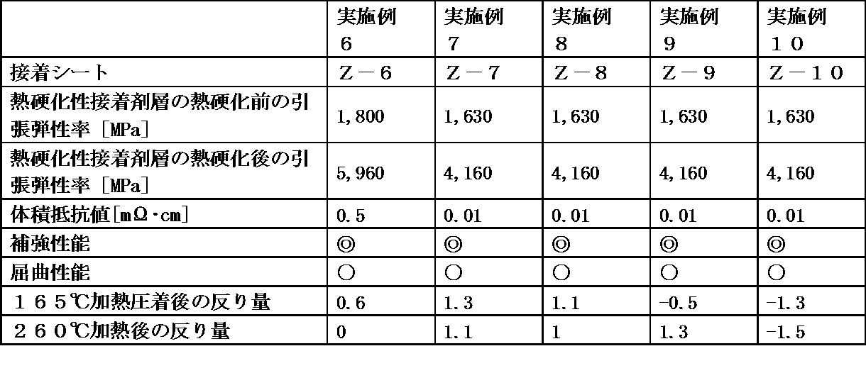
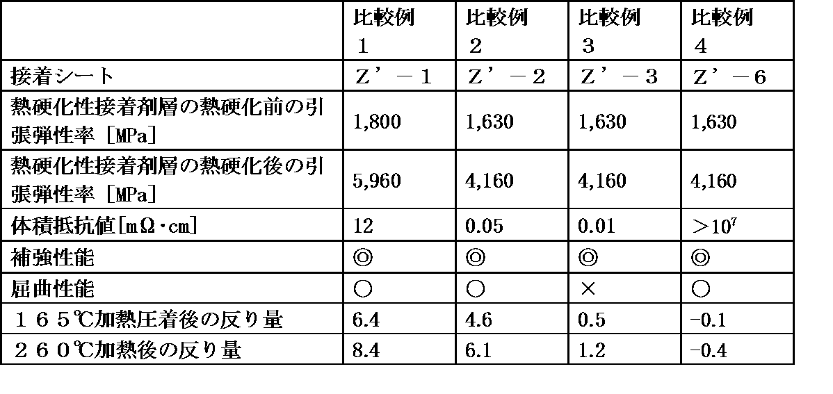
Claims (9)
- フレキシブルプリント配線板の補強に使用する熱硬化性接着シートであって、前記熱硬化性接着シートが、織布、不織布又は厚さ50μm以下の金属基材の少なくとも片面側に熱硬化性接着剤層を有するものであることを特徴とする熱硬化性接着シート。
- 前記熱硬化性接着剤層の25℃における引っ張り弾性率(x1)が5MPa~2,500MPaの範囲であり、かつ、その熱硬化物の25℃における引っ張り弾性率(x2)が2,500MPa以上である請求項1に記載の熱硬化性接着シート。
- 50μm~350μmの範囲の厚さを有する請求項1または2に記載の熱硬化性接着シート。
- 前記織布または不織布が導電性織布または導電性不織布であり、厚さが10μm~50μmの範囲である請求項1~3のいずれか1項に記載の熱硬化性接着シート。
- 前記厚さ50μm以下の金属基材がアルミニウム基材である請求項1~3のいずれか1項に記載の熱硬化性接着シート。
- 前記熱硬化性接着剤層が、熱硬化性樹脂と導電性フィラーとを含有するものである請求項1~5のいずれか1項に記載の熱硬化性接着シート。
- フレキシブルプリント配線板と補強部とが積層された構成を有する補強部付フレキシブルプリント配線板であって、前記補強部が、前記織布または不織布または厚さ50μmの金属基材の少なくとも片面側に熱硬化性接着剤層を有する熱硬化性接着シートの熱硬化物であることを特徴とする補強部付フレキシブルプリント配線板。
- フレキシブルプリント配線板の実装面に対する裏面に、請求項1~6のいずれか1項に記載の熱硬化性接着シートを貼付する工程[1]、及び、前記熱硬化性接着シートを120℃以上に加熱し熱硬化させることによって、その熱硬化物からなる補強部を形成する工程[2]を有することを特徴とする補強部付フレキシブルプリント配線板の製造方法。
- 請求項8に記載の補強部付フレキシブルプリント配線板の前記補強部の表面に、直接または他の層を介して、クッション材が積層された構成を有する電子機器。
Priority Applications (2)
| Application Number | Priority Date | Filing Date | Title |
|---|---|---|---|
| CN201680067385.0A CN108353497A (zh) | 2015-12-18 | 2016-12-06 | 热固性粘接片、带有增强部的柔性印刷配线板、其制造方法以及电子设备 |
| US15/778,369 US10426044B2 (en) | 2015-12-18 | 2016-12-06 | Thermosetting adhesive sheet, reinforcement-part-equipped flexible printed circuit, method for manufacturing reinforcement-part-equipped flexible printed circuit, and electronic device |
Applications Claiming Priority (4)
| Application Number | Priority Date | Filing Date | Title |
|---|---|---|---|
| JP2015-247331 | 2015-12-18 | ||
| JP2015247331 | 2015-12-18 | ||
| JP2016001069 | 2016-01-06 | ||
| JP2016-001069 | 2016-01-06 |
Publications (1)
| Publication Number | Publication Date |
|---|---|
| WO2017104479A1 true WO2017104479A1 (ja) | 2017-06-22 |
Family
ID=59056432
Family Applications (1)
| Application Number | Title | Priority Date | Filing Date |
|---|---|---|---|
| PCT/JP2016/086166 Ceased WO2017104479A1 (ja) | 2015-12-18 | 2016-12-06 | 熱硬化性接着シート、補強部付フレキシブルプリント配線板、その製造方法及び電子機器 |
Country Status (3)
| Country | Link |
|---|---|
| US (1) | US10426044B2 (ja) |
| CN (1) | CN108353497A (ja) |
| WO (1) | WO2017104479A1 (ja) |
Cited By (20)
| Publication number | Priority date | Publication date | Assignee | Title |
|---|---|---|---|---|
| WO2019069895A1 (ja) * | 2017-10-05 | 2019-04-11 | Dic株式会社 | フレキシブルプリント配線板補強用硬化性接着シート、補強部付フレキシブルプリント配線板、その製造方法及び電子機器 |
| JP2019065243A (ja) * | 2017-10-05 | 2019-04-25 | Dic株式会社 | フレキシブルプリント配線板補強用硬化性接着シート、補強部付フレキシブルプリント配線板、その製造方法及び電子機器 |
| US20220020530A1 (en) * | 2018-12-17 | 2022-01-20 | Nippon Steel Corporation | Laminated core and electric motor |
| US11742129B2 (en) | 2018-12-17 | 2023-08-29 | Nippon Steel Corporation | Adhesively-laminated core, manufacturing method thereof, and electric motor |
| WO2023190227A1 (ja) * | 2022-03-28 | 2023-10-05 | タツタ電線株式会社 | 両面接着シート |
| US11855485B2 (en) | 2018-12-17 | 2023-12-26 | Nippon Steel Corporation | Laminated core, method of manufacturing same, and electric motor |
| US11863017B2 (en) | 2018-12-17 | 2024-01-02 | Nippon Steel Corporation | Laminated core and electric motor |
| US11923130B2 (en) | 2018-12-17 | 2024-03-05 | Nippon Steel Corporation | Laminated core and electric motor |
| US11973369B2 (en) | 2018-12-17 | 2024-04-30 | Nippon Steel Corporation | Laminated core with center electrical steel sheets adhered with adhesive and some electrical steel sheets fixed to each other on both ends of the center sheets |
| US11979059B2 (en) | 2018-12-17 | 2024-05-07 | Nippon Steel Corporation | Laminated core and electric motor |
| US11990795B2 (en) | 2018-12-17 | 2024-05-21 | Nippon Steel Corporation | Adhesively-laminated core for stator, method of manufacturing same, and electric motor |
| US11996231B2 (en) | 2018-12-17 | 2024-05-28 | Nippon Steel Corporation | Laminated core and electric motor |
| US12068097B2 (en) | 2018-12-17 | 2024-08-20 | Nippon Steel Corporation | Laminated core, core block, electric motor and method of producing core block |
| US12074476B2 (en) | 2018-12-17 | 2024-08-27 | Nippon Steel Corporation | Adhesively-laminated core for stator and electric motor |
| US12081068B2 (en) | 2018-12-17 | 2024-09-03 | Nippon Steel Corporation | Laminated core with some electrical steel sheets adhered with adhesive and some electrical steel sheets fixed to each other |
| US12098190B2 (en) | 2018-09-06 | 2024-09-24 | The Trustees Of The University Of Pennsylvania And | Humanized anti-C5 antibodies and uses thereof |
| US12104096B2 (en) | 2018-12-17 | 2024-10-01 | Nippon Steel Corporation | Laminated core, laminated core manufacturing method, and electric motor |
| US12154711B2 (en) | 2018-12-17 | 2024-11-26 | Nippon Steel Corporation | Adhesively-laminated core for stator and electric motor |
| US12261482B2 (en) | 2018-12-17 | 2025-03-25 | Nippon Steel Corporation | Laminated core and electric motor |
| US12266971B2 (en) | 2018-12-17 | 2025-04-01 | Nippon Steel Corporation | Adhesively-laminated core for stator, method of manufacturing the same, and electric motor |
Families Citing this family (2)
| Publication number | Priority date | Publication date | Assignee | Title |
|---|---|---|---|---|
| WO2020158692A1 (ja) * | 2019-01-28 | 2020-08-06 | 日本ゼオン株式会社 | 電磁波吸収シート |
| JP7327700B1 (ja) * | 2023-04-05 | 2023-08-16 | 東洋インキScホールディングス株式会社 | ロール状導電性接合シート、金属補強板付き配線板、および電子機器 |
Citations (5)
| Publication number | Priority date | Publication date | Assignee | Title |
|---|---|---|---|---|
| JP2000261107A (ja) * | 1999-03-08 | 2000-09-22 | Tomoegawa Paper Co Ltd | 電磁波シールド用金属繊維シート付フレキシブルプリント基板及びその製造方法 |
| JP2005057097A (ja) * | 2003-08-06 | 2005-03-03 | Nec Saitama Ltd | フレキシブルプリント配線板の補強板形状 |
| JP2006339173A (ja) * | 2005-05-31 | 2006-12-14 | Sumitomo Bakelite Co Ltd | フレキシブル配線板の補強部材およびフレキシブル配線板 |
| JP2009200292A (ja) * | 2008-02-22 | 2009-09-03 | Sumitomo Electric Ind Ltd | フレキシブルプリント配線板および配線板の凸構造の形成方法 |
| JP2009218443A (ja) * | 2008-03-11 | 2009-09-24 | Sumitomo Electric Ind Ltd | 金属補強板を備えたフレキシブルプリント配線板 |
Family Cites Families (33)
| Publication number | Priority date | Publication date | Assignee | Title |
|---|---|---|---|---|
| US4647508A (en) * | 1984-07-09 | 1987-03-03 | Rogers Corporation | Flexible circuit laminate |
| US4634631A (en) * | 1985-07-15 | 1987-01-06 | Rogers Corporation | Flexible circuit laminate and method of making the same |
| US5103293A (en) * | 1990-12-07 | 1992-04-07 | International Business Machines Corporation | Electronic circuit packages with tear resistant organic cores |
| US5663530A (en) * | 1995-08-01 | 1997-09-02 | Minnesota Mining And Manufacturing Company | Wire bond tape ball grid array package |
| US5844168A (en) * | 1995-08-01 | 1998-12-01 | Minnesota Mining And Manufacturing Company | Multi-layer interconnect sutructure for ball grid arrays |
| CN1217130C (zh) * | 1997-06-30 | 2005-08-31 | 株式会社丰臣 | 操作机器用面板 |
| WO1999007198A1 (en) * | 1997-07-31 | 1999-02-11 | Toyotomi Co., Ltd. | Console panel for equipment |
| US20010052647A1 (en) * | 1998-05-07 | 2001-12-20 | 3M Innovative Properties Company | Laminated integrated circuit package |
| US6140707A (en) * | 1998-05-07 | 2000-10-31 | 3M Innovative Properties Co. | Laminated integrated circuit package |
| JP2000138262A (ja) * | 1998-10-31 | 2000-05-16 | Anam Semiconductor Inc | チップスケ―ル半導体パッケ―ジ及びその製造方法 |
| JP3195590B2 (ja) * | 1999-04-27 | 2001-08-06 | 日東電工株式会社 | フレキシブル配線板 |
| JP3895125B2 (ja) * | 2001-04-12 | 2007-03-22 | 日東電工株式会社 | 補強板付フレキシブルプリント回路板 |
| JP4222882B2 (ja) * | 2003-06-03 | 2009-02-12 | 日東電工株式会社 | 配線回路基板 |
| JP4436803B2 (ja) * | 2003-12-26 | 2010-03-24 | 積水化学工業株式会社 | 離型フィルム |
| JP2007204598A (ja) * | 2006-02-01 | 2007-08-16 | Nippon Kayaku Co Ltd | 樹脂組成物およびその硬化物 |
| US7649254B2 (en) * | 2006-05-01 | 2010-01-19 | Flextronics Ap, Llc | Conductive stiffener for a flexible substrate |
| JP2007324236A (ja) * | 2006-05-30 | 2007-12-13 | Nof Corp | プリント配線板用フィルムに用いる樹脂組成物及びその用途 |
| US8064033B2 (en) * | 2006-06-15 | 2011-11-22 | Sharp Kabushiki Kaisha | Display and process for producing the same |
| JP4962156B2 (ja) * | 2007-06-19 | 2012-06-27 | 住友金属鉱山株式会社 | 導電性接着剤 |
| EP2357876A4 (en) * | 2008-09-05 | 2012-04-25 | Sumitomo Bakelite Co | Electroconductive connecting material, method for connecting terminals to each other using the electroconductive connecting material, and method for manufacturing connecting terminal |
| CN101778540A (zh) * | 2009-01-12 | 2010-07-14 | 健鼎(无锡)电子有限公司 | 板件表面处理方法 |
| TW201110802A (en) * | 2009-06-24 | 2011-03-16 | Seiko Epson Corp | Electro-optical device, electronic device, and illumination apparatus |
| WO2012049898A1 (ja) * | 2010-10-15 | 2012-04-19 | 日本電気株式会社 | 部品内蔵モジュール及びこれを備える電子機器並びに部品内蔵モジュールの製造方法 |
| KR102021845B1 (ko) * | 2011-04-28 | 2019-09-18 | 가부시키가이샤 가네카 | 보강판 일체형 플렉서블 프린트 기판 |
| KR101253991B1 (ko) * | 2011-12-07 | 2013-04-11 | 도레이첨단소재 주식회사 | 연성인쇄회로기판용 점착제 조성물 및 이를 이용한 연성인쇄회로기판용 점착필름 |
| CN105584149A (zh) * | 2012-01-20 | 2016-05-18 | 旭化成株式会社 | 树脂组合物、层积体、多层印刷线路板和多层柔性线路板及其制造方法 |
| KR101982620B1 (ko) | 2013-02-26 | 2019-05-27 | 타츠타 전선 주식회사 | 플렉시블 프린트 배선판용 보강 부재, 플렉시블 프린트 배선판, 및 차폐 프린트 배선판 |
| JP6163803B2 (ja) * | 2013-03-14 | 2017-07-19 | 味の素株式会社 | 樹脂組成物 |
| TWI490115B (zh) * | 2014-03-07 | 2015-07-01 | Azotek Co Ltd | 金屬基板及其製作方法 |
| TWI488549B (zh) * | 2014-03-07 | 2015-06-11 | Azotek Co Ltd | 金屬基板及其製作方法 |
| CN106576424B (zh) * | 2014-08-29 | 2020-08-25 | 拓自达电线株式会社 | 柔性印刷配线板用增强部件和具备柔性印刷配线板用增强部件的柔性印刷配线板 |
| JP2016058509A (ja) * | 2014-09-09 | 2016-04-21 | 株式会社東芝 | 補強板付きフレキシブルプリント配線板の製造方法およびフレキシブルプリント配線板中間体 |
| CN104527170A (zh) * | 2014-12-16 | 2015-04-22 | 苏州城邦达力材料科技有限公司 | 一种印刷线路板中金属钢补强用导电胶膜及其制造工艺 |
-
2016
- 2016-12-06 CN CN201680067385.0A patent/CN108353497A/zh active Pending
- 2016-12-06 US US15/778,369 patent/US10426044B2/en active Active
- 2016-12-06 WO PCT/JP2016/086166 patent/WO2017104479A1/ja not_active Ceased
Patent Citations (5)
| Publication number | Priority date | Publication date | Assignee | Title |
|---|---|---|---|---|
| JP2000261107A (ja) * | 1999-03-08 | 2000-09-22 | Tomoegawa Paper Co Ltd | 電磁波シールド用金属繊維シート付フレキシブルプリント基板及びその製造方法 |
| JP2005057097A (ja) * | 2003-08-06 | 2005-03-03 | Nec Saitama Ltd | フレキシブルプリント配線板の補強板形状 |
| JP2006339173A (ja) * | 2005-05-31 | 2006-12-14 | Sumitomo Bakelite Co Ltd | フレキシブル配線板の補強部材およびフレキシブル配線板 |
| JP2009200292A (ja) * | 2008-02-22 | 2009-09-03 | Sumitomo Electric Ind Ltd | フレキシブルプリント配線板および配線板の凸構造の形成方法 |
| JP2009218443A (ja) * | 2008-03-11 | 2009-09-24 | Sumitomo Electric Ind Ltd | 金属補強板を備えたフレキシブルプリント配線板 |
Cited By (21)
| Publication number | Priority date | Publication date | Assignee | Title |
|---|---|---|---|---|
| WO2019069895A1 (ja) * | 2017-10-05 | 2019-04-11 | Dic株式会社 | フレキシブルプリント配線板補強用硬化性接着シート、補強部付フレキシブルプリント配線板、その製造方法及び電子機器 |
| JP2019065243A (ja) * | 2017-10-05 | 2019-04-25 | Dic株式会社 | フレキシブルプリント配線板補強用硬化性接着シート、補強部付フレキシブルプリント配線板、その製造方法及び電子機器 |
| US12098190B2 (en) | 2018-09-06 | 2024-09-24 | The Trustees Of The University Of Pennsylvania And | Humanized anti-C5 antibodies and uses thereof |
| US11979059B2 (en) | 2018-12-17 | 2024-05-07 | Nippon Steel Corporation | Laminated core and electric motor |
| US11996231B2 (en) | 2018-12-17 | 2024-05-28 | Nippon Steel Corporation | Laminated core and electric motor |
| US11855485B2 (en) | 2018-12-17 | 2023-12-26 | Nippon Steel Corporation | Laminated core, method of manufacturing same, and electric motor |
| US11863017B2 (en) | 2018-12-17 | 2024-01-02 | Nippon Steel Corporation | Laminated core and electric motor |
| US11915860B2 (en) * | 2018-12-17 | 2024-02-27 | Nippon Steel Corporation | Laminated core and electric motor |
| US11923130B2 (en) | 2018-12-17 | 2024-03-05 | Nippon Steel Corporation | Laminated core and electric motor |
| US11973369B2 (en) | 2018-12-17 | 2024-04-30 | Nippon Steel Corporation | Laminated core with center electrical steel sheets adhered with adhesive and some electrical steel sheets fixed to each other on both ends of the center sheets |
| US11742129B2 (en) | 2018-12-17 | 2023-08-29 | Nippon Steel Corporation | Adhesively-laminated core, manufacturing method thereof, and electric motor |
| US11990795B2 (en) | 2018-12-17 | 2024-05-21 | Nippon Steel Corporation | Adhesively-laminated core for stator, method of manufacturing same, and electric motor |
| US12266971B2 (en) | 2018-12-17 | 2025-04-01 | Nippon Steel Corporation | Adhesively-laminated core for stator, method of manufacturing the same, and electric motor |
| US12068097B2 (en) | 2018-12-17 | 2024-08-20 | Nippon Steel Corporation | Laminated core, core block, electric motor and method of producing core block |
| US12074476B2 (en) | 2018-12-17 | 2024-08-27 | Nippon Steel Corporation | Adhesively-laminated core for stator and electric motor |
| US12081068B2 (en) | 2018-12-17 | 2024-09-03 | Nippon Steel Corporation | Laminated core with some electrical steel sheets adhered with adhesive and some electrical steel sheets fixed to each other |
| US20220020530A1 (en) * | 2018-12-17 | 2022-01-20 | Nippon Steel Corporation | Laminated core and electric motor |
| US12104096B2 (en) | 2018-12-17 | 2024-10-01 | Nippon Steel Corporation | Laminated core, laminated core manufacturing method, and electric motor |
| US12154711B2 (en) | 2018-12-17 | 2024-11-26 | Nippon Steel Corporation | Adhesively-laminated core for stator and electric motor |
| US12261482B2 (en) | 2018-12-17 | 2025-03-25 | Nippon Steel Corporation | Laminated core and electric motor |
| WO2023190227A1 (ja) * | 2022-03-28 | 2023-10-05 | タツタ電線株式会社 | 両面接着シート |
Also Published As
| Publication number | Publication date |
|---|---|
| US10426044B2 (en) | 2019-09-24 |
| US20180352660A1 (en) | 2018-12-06 |
| CN108353497A (zh) | 2018-07-31 |
Similar Documents
| Publication | Publication Date | Title |
|---|---|---|
| US10426044B2 (en) | Thermosetting adhesive sheet, reinforcement-part-equipped flexible printed circuit, method for manufacturing reinforcement-part-equipped flexible printed circuit, and electronic device | |
| KR101846474B1 (ko) | 도전성 시트 및 그 제조 방법, 및 전자 부품 | |
| TWI608791B (zh) | 撓性印刷電路板用電磁波遮蔽材 | |
| JP6435540B2 (ja) | 電磁波シールドフィルム、電磁波シールドフィルム付きフレキシブルプリント配線板、およびそれら製造方法 | |
| CN102176808B (zh) | 层叠体、基板的制造方法、基板及半导体装置 | |
| CN203225988U (zh) | 屏蔽膜和屏蔽印刷电路板 | |
| CN101772996A (zh) | 印刷布线板用屏蔽膜以及印刷布线板 | |
| CN108353496B (zh) | 柔性印刷配线板增强用热固性材料、带有增强部的柔性印刷配线板、其制造方法及电子设备 | |
| TWI796476B (zh) | 導電性接著片 | |
| CN105684559A (zh) | 印刷配线板、印刷配线板的制造方法及电子装置 | |
| CN110022639A (zh) | 电磁波屏蔽膜 | |
| JP7361447B2 (ja) | 導電性樹脂組成物、導電性接着シート及び積層体 | |
| JP2017110128A (ja) | 熱硬化性接着シート、物品及び物品の製造方法 | |
| JP6452002B2 (ja) | フレキシブルプリント配線板補強用熱硬化性材料、補強部付フレキシブルプリント配線板、その製造方法及び電子機器 | |
| JP6460419B2 (ja) | 補強部付フレキシブルプリント配線板、その製造方法及び電子機器 | |
| TWI743368B (zh) | 電磁波屏蔽膜及屏蔽印刷配線基板 | |
| JP7067056B2 (ja) | 補強板接着固定用接着シート | |
| TW201839078A (zh) | 熱硬化性黏著片、附設補強部之撓性印刷電路板、其製造方法以及電子設備 | |
| JP2017118102A (ja) | 熱硬化性接着シート、補強部付フレキシブルプリント配線板、その製造方法及び電子機器 | |
| JP2016157781A (ja) | 導電性接着シート、シールドプリント配線板および電子機器 | |
| JP2012158681A (ja) | エポキシ樹脂組成物 | |
| JP2012051232A (ja) | 積層シートの製造方法および積層シート | |
| JP6604369B2 (ja) | フレキシブルプリント配線板補強用硬化性接着シート、補強部付フレキシブルプリント配線板、その製造方法及び電子機器 | |
| JP7654579B2 (ja) | 電磁波シールドフィルム、及び電磁波シールドフィルム付きプリント配線板 | |
| CN114945268B (zh) | 电磁波屏蔽膜和带电磁波屏蔽膜印刷布线板 |
Legal Events
| Date | Code | Title | Description |
|---|---|---|---|
| 121 | Ep: the epo has been informed by wipo that ep was designated in this application |
Ref document number: 16875462 Country of ref document: EP Kind code of ref document: A1 |
|
| NENP | Non-entry into the national phase |
Ref country code: DE |
|
| 122 | Ep: pct application non-entry in european phase |
Ref document number: 16875462 Country of ref document: EP Kind code of ref document: A1 |