WO2017104419A1 - 車両用ワイパ装置 - Google Patents
車両用ワイパ装置 Download PDFInfo
- Publication number
- WO2017104419A1 WO2017104419A1 PCT/JP2016/085636 JP2016085636W WO2017104419A1 WO 2017104419 A1 WO2017104419 A1 WO 2017104419A1 JP 2016085636 W JP2016085636 W JP 2016085636W WO 2017104419 A1 WO2017104419 A1 WO 2017104419A1
- Authority
- WO
- WIPO (PCT)
- Prior art keywords
- mark
- water receiving
- receiving member
- pivot
- pivot shaft
- Prior art date
- Legal status (The legal status is an assumption and is not a legal conclusion. Google has not performed a legal analysis and makes no representation as to the accuracy of the status listed.)
- Ceased
Links
Images





Classifications
-
- B—PERFORMING OPERATIONS; TRANSPORTING
- B60—VEHICLES IN GENERAL
- B60S—SERVICING, CLEANING, REPAIRING, SUPPORTING, LIFTING, OR MANOEUVRING OF VEHICLES, NOT OTHERWISE PROVIDED FOR
- B60S1/00—Cleaning of vehicles
- B60S1/02—Cleaning windscreens, windows or optical devices
- B60S1/04—Wipers or the like, e.g. scrapers
- B60S1/043—Attachment of the wiper assembly to the vehicle
- B60S1/0433—Attachement of a wiper modular assembly to the vehicle
-
- B—PERFORMING OPERATIONS; TRANSPORTING
- B60—VEHICLES IN GENERAL
- B60S—SERVICING, CLEANING, REPAIRING, SUPPORTING, LIFTING, OR MANOEUVRING OF VEHICLES, NOT OTHERWISE PROVIDED FOR
- B60S1/00—Cleaning of vehicles
- B60S1/02—Cleaning windscreens, windows or optical devices
- B60S1/04—Wipers or the like, e.g. scrapers
- B60S1/32—Wipers or the like, e.g. scrapers characterised by constructional features of wiper blade arms or blades
- B60S1/34—Wiper arms; Mountings therefor
-
- B—PERFORMING OPERATIONS; TRANSPORTING
- B60—VEHICLES IN GENERAL
- B60S—SERVICING, CLEANING, REPAIRING, SUPPORTING, LIFTING, OR MANOEUVRING OF VEHICLES, NOT OTHERWISE PROVIDED FOR
- B60S1/00—Cleaning of vehicles
- B60S1/02—Cleaning windscreens, windows or optical devices
- B60S1/04—Wipers or the like, e.g. scrapers
- B60S1/06—Wipers or the like, e.g. scrapers characterised by the drive
- B60S1/16—Means for transmitting drive
- B60S1/18—Means for transmitting drive mechanically
- B60S1/24—Means for transmitting drive mechanically by rotary cranks
- B60S1/245—Means for transmitting drive mechanically by rotary cranks with particular rod arrangements between the motor driven axle and the wiper arm axle
-
- B—PERFORMING OPERATIONS; TRANSPORTING
- B60—VEHICLES IN GENERAL
- B60S—SERVICING, CLEANING, REPAIRING, SUPPORTING, LIFTING, OR MANOEUVRING OF VEHICLES, NOT OTHERWISE PROVIDED FOR
- B60S1/00—Cleaning of vehicles
- B60S1/02—Cleaning windscreens, windows or optical devices
- B60S1/04—Wipers or the like, e.g. scrapers
- B60S1/0413—Modular wiper assembly
- B60S1/0422—Modular wiper assembly having a separate transverse element
- B60S1/0425—Modular wiper assembly having a separate transverse element characterised by the attachment of the wiper shaft holders to the transverse element
-
- B—PERFORMING OPERATIONS; TRANSPORTING
- B60—VEHICLES IN GENERAL
- B60S—SERVICING, CLEANING, REPAIRING, SUPPORTING, LIFTING, OR MANOEUVRING OF VEHICLES, NOT OTHERWISE PROVIDED FOR
- B60S1/00—Cleaning of vehicles
- B60S1/02—Cleaning windscreens, windows or optical devices
- B60S1/04—Wipers or the like, e.g. scrapers
- B60S1/06—Wipers or the like, e.g. scrapers characterised by the drive
- B60S1/16—Means for transmitting drive
- B60S1/18—Means for transmitting drive mechanically
- B60S1/24—Means for transmitting drive mechanically by rotary cranks
-
- B—PERFORMING OPERATIONS; TRANSPORTING
- B60—VEHICLES IN GENERAL
- B60S—SERVICING, CLEANING, REPAIRING, SUPPORTING, LIFTING, OR MANOEUVRING OF VEHICLES, NOT OTHERWISE PROVIDED FOR
- B60S1/00—Cleaning of vehicles
- B60S1/02—Cleaning windscreens, windows or optical devices
- B60S1/04—Wipers or the like, e.g. scrapers
- B60S1/28—Wipers or the like, e.g. scrapers characterised by a plurality of wipers
-
- B—PERFORMING OPERATIONS; TRANSPORTING
- B60—VEHICLES IN GENERAL
- B60S—SERVICING, CLEANING, REPAIRING, SUPPORTING, LIFTING, OR MANOEUVRING OF VEHICLES, NOT OTHERWISE PROVIDED FOR
- B60S1/00—Cleaning of vehicles
- B60S1/02—Cleaning windscreens, windows or optical devices
- B60S1/04—Wipers or the like, e.g. scrapers
- B60S1/32—Wipers or the like, e.g. scrapers characterised by constructional features of wiper blade arms or blades
- B60S1/34—Wiper arms; Mountings therefor
- B60S1/3488—Means for mounting wiper arms onto the vehicle
- B60S1/349—Means for mounting the wiper bearing to the vehicle body
-
- B—PERFORMING OPERATIONS; TRANSPORTING
- B60—VEHICLES IN GENERAL
- B60R—VEHICLES, VEHICLE FITTINGS, OR VEHICLE PARTS, NOT OTHERWISE PROVIDED FOR
- B60R13/00—Elements for body-finishing, identifying, or decorating; Arrangements or adaptations for advertising purposes
- B60R13/07—Water drainage or guide means not integral with roof structure
-
- B—PERFORMING OPERATIONS; TRANSPORTING
- B60—VEHICLES IN GENERAL
- B60S—SERVICING, CLEANING, REPAIRING, SUPPORTING, LIFTING, OR MANOEUVRING OF VEHICLES, NOT OTHERWISE PROVIDED FOR
- B60S1/00—Cleaning of vehicles
- B60S1/02—Cleaning windscreens, windows or optical devices
- B60S1/04—Wipers or the like, e.g. scrapers
- B60S1/0491—Additional elements being fixed on wipers or parts of wipers not otherwise provided for, e.g. covers, antennae or lights
Definitions
- the present disclosure relates to a vehicle wiper device.
- a vehicle wiper device disclosed in Japanese Patent Application Laid-Open No. 2015-105025 is a so-called module type in which a pair of left and right pivot holders that rotatably support a pair of pivot shafts are connected to each other by a frame member (pipe frame or the like). It is configured as a wiper device.
- the water receiving member is assembled to each of the pair of left and right pivot holders.
- the liquid entering from the tip end side of the pivot shaft is blocked by the water receiving member, and the liquid is discharged from the discharge portion of the water receiving member.
- the posture of the water receiving member (specifically, the direction of the discharge portion of the water receiving member as seen from the axial direction of the pivot shaft) is different for each type of vehicle wiper device, There may be differences in the holder.
- the water receiving member can be shared by making each pivot holder an assembly structure corresponding to the posture of the water receiving member.
- the aspect of the present disclosure is intended to provide a vehicle wiper device that can improve the assembling property of the water receiving member while increasing the versatility of the water receiving member in consideration of the above fact.
- the dual-purpose wiper device is a pivot shaft that is rotated by a driving force of a wiper motor, a pivot holder that rotatably supports the pivot shaft, and the pivot holder.
- a water receiving portion disposed on the radially outer side of the water receiving portion, and a discharge portion that extends from a predetermined position of the water receiving portion to the radially outer side of the pivot shaft and discharges the liquid received by the water receiving portion.
- a plurality of first marks serving as marks for assembling the water receiving member to the pivot holder, the water receiving member being formed on the pivot holder.
- the pivot holder has a plurality of types, and the direction in which the water receiving member is attached to the pivot holder is different for each of the plurality of types of the pivot holder, and the second mark is the type of the pivot holder.
- each of the plurality of first marks has a determination mark and a positioning mark according to the plurality of types of the pivot holder, and the determination mark of the second mark.
- the positioning mark and the discrimination mark and the positioning mark of each of the plurality of first marks correspond to the discrimination mark of the second mark and the discrimination mark of the first mark, and the second mark So that the positioning mark of the mark and the positioning mark of the first mark face each other in the radial direction of the pivot shaft.
- the pivot shaft is rotatably supported by the pivot holder, and the pivot shaft is rotated by the driving force of the wiper motor.
- a water receiving member is assembled to the pivot holder.
- the water receiving member includes a water receiving portion disposed on the radially outer side of the pivot shaft, and a discharge that extends from a predetermined position of the water receiving portion to the radially outer side of the pivot shaft and discharges the liquid received by the water receiving portion.
- a plurality of first marks serving as marks for assembling the water receiving member to the pivot holder are formed on the water receiving member.
- the pivot holder is formed with a second mark that serves as an indicator of a proper assembly posture of the water receiving member to the pivot holder.
- the second mark is paired with any one of the plurality of first marks.
- the water receiving member can be shared with respect to various types of vehicle wiper devices, and the water receiving member can be erroneously used. Assembly can be prevented. Further, for example, by forming the first mark and the second mark corresponding to the pivot holders on the driver side and the passenger seat side, the water receiving member with respect to the pivot holders on the driver side and the passenger seat side is provided. While attempting to share, it is possible to prevent erroneous assembly of the water receiving member.
- the vehicle wiper device is on one side with respect to a reference line that passes through the axis of the pivot shaft and extends in the extending direction of the discharge portion when viewed from the distal end side of the pivot shaft.
- a plurality of the first marks are formed.
- the water receiving member is shared with the pivot holder on the driver's seat side of the apparatus, it is possible to prevent erroneous assembly of the water receiving member.
- the pivot shaft includes a first pivot shaft and a second pivot shaft that are rotated by transmitting a driving force of the wiper motor via a link mechanism.
- the pivot holder includes a first pivot holder that rotatably supports the first pivot shaft, and a second pivot holder that rotatably supports the second pivot shaft, and the pivot shaft
- a plurality of first marks are respectively formed on both sides of a reference line passing through the axis of the pivot shaft and extending in the extending direction of the discharge portion when viewed from the front end side of the first pivot holder.
- the second mark is formed on each of the second pivot holders.
- the first mark and the second mark are disposed so as to be visible when viewed from the distal end side of the pivot shaft.
- the water receiving member has a receiving portion having a receiving surface approved for viewing when viewed from the distal end side of the pivot shaft, and the first mark is formed on the receiving surface.
- the water receiving member can be assembled to the pivot holder from the tip end side of the pivot shaft while confirming the first mark and the second mark. For this reason, the assembling property of the water receiving member can be further improved.
- the water receiving member protrudes from the water receiving portion to the proximal end side of the pivot shaft, and is in the circumferential engagement state with the pivot holder.
- An engagement protrusion that restricts movement of the water receiving member in the circumferential direction, and protrudes from the water receiving portion to the proximal end side of the pivot shaft, and in an axially engaged state with the pivot holder,
- An engagement claw portion that restricts movement toward the distal end side, and when viewed from the axial direction of the pivot shaft, the engagement claw portion is disposed on the discharge portion side with respect to the pivot shaft, and the engagement A protrusion is disposed on the opposite side of the discharge portion with respect to the pivot shaft.
- the pivot holder includes a sleeve that is formed with a first engaged portion with which the engaging claw portion is engaged and a second engaged portion with which the engaging protrusion is engaged and supports the pivot shaft. .
- the movement of the water receiving member with respect to the pivot holder in the circumferential direction is restricted by the engaging protrusion of the water receiving member, and the pivot of the water receiving member with respect to the pivot holder by the engaging claw portion of the water receiving member Movement to the shaft tip side is limited.
- attachment state to the pivot holder of a water receiving member can be maintained.
- the engaging claw portion is disposed on the discharge portion side with respect to the pivot shaft. For this reason, the assembly state of the water receiving member to the pivot holder can be maintained while the rigidity of the discharge portion is increased by the engaging claw portion.
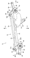
- FIG. 2 is a plan view of the entire vehicle wiper device shown in FIG. 1 as viewed from above the vehicle.
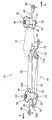
- FIG. 3 is a perspective view of the entire vehicle wiper device shown in FIG.
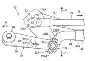
- FIG. 4 is a front view showing a state where the water receiving member shown in FIG. 1A is removed from the first pivot holder.
- FIG. 5 is a rear view showing a state in which the water receiving member shown in FIG.
- FIG. 1A is removed from the first pivot holder. It is a side view of the water receiving member shown by FIG. 1A. It is a top view of the water receiving member shown by FIG. 6A. It is a top view which shows the example by which a water receiving member is arrange
- FIG. 8A It is a top view which shows an example by which a water receiving member is arrange
- the vehicle wiper device 10 is a wiper device for a front windshield glass of a vehicle (automobile), and is configured as a so-called module-type wiper device.
- the vehicle wiper device 10 extends in the vehicle width direction of the vehicle and is disposed on the inner side of the vehicle with respect to the cowl louver (not shown) of the vehicle.
- FIG. 2 is a plan view of the overall configuration of the vehicle wiper apparatus 10 as viewed from the upper side of the vehicle.
- FIG. 3 shows the overall configuration of the vehicle wiper apparatus 10 as viewed from an obliquely upper front side of the vehicle. It is shown in a perspective view.
- An arrow A and an arrow B appropriately shown in the drawings indicate a vehicle width direction (longitudinal direction of the vehicle wiper device 10), an arrow C indicates a vehicle front side (hereinafter simply referred to as a front side), and an arrow D Indicates the rear side of the vehicle (hereinafter simply referred to as the rear side).
- the vehicle wiper device 10 includes a first pivot holder 20, a first pivot shaft 30, a hollow frame 40, a second pivot holder 50, and a second pivot shaft 60. It is configured to include.
- the vehicle wiper device 10 includes a wiper motor 70, a link mechanism 74, and a water receiving member 80. Each configuration will be described below.
- the first pivot holder 20 and the second pivot holder 50 are examples of “pivot holders”.
- the first pivot shaft 30 and the second pivot shaft 60 are examples of “pivot shafts”.
- the 1st pivot holder 20 is provided in the longitudinal direction one side (arrow A direction side of FIG.2 and FIG.3) of the wiper apparatus 10 for vehicles.
- the first pivot holder 20 is manufactured by die casting using an aluminum alloy or the like. 4 and 5, the first pivot holder 20 includes a sleeve 22 that rotatably supports a first pivot shaft 30 described later (element grasped as a “support portion” in a broad sense).
- the sleeve 22 is formed in a substantially cylindrical shape.
- a connecting portion 24 is formed integrally with the sleeve 22.
- the connecting portion 24 is formed in a solid shaft shape, and extends from the intermediate portion in the axial direction of the sleeve 22 to the other longitudinal side of the vehicle wiper device 10 (the arrow B direction side in FIGS. 2 and 3). Has been.
- a fixed leg portion 26 is integrally provided on the outer peripheral portion of the sleeve 22.
- the fixed leg portion 26 is formed in a plate shape in which the substantially axial direction of the sleeve 22 is a plate thickness direction, and is one side in the longitudinal direction of the vehicle wiper device 10 from the intermediate portion in the axial direction of the sleeve 22 (what is the connecting portion 24? The other side). And the front-end
- the outer peripheral portion of the sleeve 22 is engaged with a first engaged portion 22 ⁇ / b> A (engagement claw portion 86 and engagement protrusion 88 of a water receiving member 80 described later). 4) and the second engaged portion 22B (see FIG. 5) are integrally formed.
- the first engaged portion 22 ⁇ / b> A protrudes forward from the sleeve 22 and is formed in a substantially H-shaped block shape in a front view. That is, the first engaged portion 22A includes a recess 22A1 that is open to one side of the sleeve 22 in the axial direction (the direction of arrow E in FIG. 4) and the other side of the sleeve 22 in the axial direction (the direction of arrow F in FIG. 4). A recess 22A2 that is open to the side).
- the second engaged portion 22 ⁇ / b> B protrudes rearward from the sleeve 22.
- the second engaged portion 22B is opposite to the first engaged portion 22A with respect to the axis of the sleeve 22 (more specifically, a point-symmetrical position). Is arranged.
- the second engaged portion 22B is formed in a substantially U-shaped block shape when viewed from the rear side. That is, the second engaged portion 22B is formed with a recess 22B1 that is open to one side in the axial direction of the sleeve 22.
- the first pivot shaft 30 is inserted into the sleeve 22 and is rotatably supported by the sleeve 22.
- a proximal end portion of a wiper arm (not shown) is fixed to a distal end portion (an end portion on the arrow E direction side in FIGS. 4 and 5) of the first pivot shaft 30, and a distal end portion of the wiper arm is illustrated in the figure. Not wiper blades are connected.
- a first lever 32 that extends outward in the radial direction of the first pivot shaft 30 is fixed to the proximal end portion of the first pivot shaft 30.
- the first lever 32 rotates about the first pivot shaft 30, so that the wiper arm rotates about the first pivot shaft 30 together with the first pivot shaft 30, and the wiper blade moves the front windshield of the vehicle.
- the shield glass is wiped off.
- the first pivot shaft 30 is tilted so as to tilt forward with respect to the vertical direction of the vehicle.
- the hollow frame 40 is made of a long hollow pipe material and is arranged coaxially with the connecting portion 24 of the first pivot holder 20.
- One end portion of the hollow frame 40 in the longitudinal direction is a first fixing portion 40A.
- the connecting portion 24 of the first pivot holder 20 is fitted into the first fixing portion 40A, and the first fixing portion 40A is fixed to the connecting portion 24 by caulking or the like.
- the other end portion in the longitudinal direction of the hollow frame 40 is a second fixing portion 40B, and the second fixing portion 40B is fixed to a second pivot holder 50 described later by caulking or the like.
- a bracket 42 for attaching a wiper motor 70 to be described later is fixed to an intermediate portion in the longitudinal direction of the hollow frame 40.
- the bracket 42 is formed in a substantially triangular plate shape having a substantially axial direction of the first pivot shaft 30 as a plate thickness direction, and protrudes from the hollow frame 40 to the front side.
- the front end of the bracket 42 protruding to the front side is fixed to the vehicle body in a floating state via a rubber grommet 44.
- the 2nd pivot holder 50 is provided in the longitudinal direction other side (arrow B direction side of FIG.2 and FIG.3) of the wiper apparatus 10 for vehicles. Similar to the first pivot holder 20, the second pivot holder 50 is manufactured by die casting using an aluminum alloy or the like. Further, the second pivot holder 50 has a cylindrical sleeve 52 (an element grasped as a “support portion” in a broad sense), and the sleeve 52 (see FIG. 3) is the first pivot holder.
- the 20 sleeves 22 are arranged substantially in parallel.
- a solid shaft-like connecting portion 54 is integrally provided on the outer peripheral portion of the sleeve 52.
- the connecting portion 54 extends from an intermediate portion in the axial direction of the sleeve 52 to one side in the longitudinal direction of the vehicle wiper device 10, and a distal end portion of the connecting portion 54 is arranged coaxially with the hollow frame 40.
- tip part of the connection part 54 is inserted in the 2nd fixing
- the first pivot holder 20 and the second pivot holder 50 are connected to each other by the hollow frame 40.
- a fixed leg portion 56 is integrally provided on the outer peripheral portion of the sleeve 52, and the fixed leg portion 56 is formed in a plate shape in which the substantially axial direction of the sleeve 52 is a plate thickness direction, and in the axial direction of the sleeve 52. It extends from the intermediate portion to the other side in the longitudinal direction of the vehicle wiper device 10 (the side opposite to the connecting portion 54). And the front-end
- the outer peripheral portion of the sleeve 52 is engaged with an engaging claw portion 86 and an engaging protrusion 88 of a water receiving member 80, which will be described later, respectively.
- the joint is formed integrally.
- the first engaged portion and the second engaged portion are the same as the first engaged portion 22A (see FIG. 4) and the second engaged portion 22B (see FIG. 5) of the first pivot holder 20. It is configured. That is, the first engaged portion of the second pivot holder 50 protrudes forward from the sleeve 52 and is formed in a substantially H-shaped block shape in front view. Further, the second engaged portion of the second pivot holder 50 protrudes rearward from the sleeve 52 and is formed in a substantially U-shaped block shape when viewed from the rear side.
- the second pivot shaft 60 is inserted into the sleeve 52 and is rotatably supported by the sleeve 52.
- a proximal end portion of a wiper arm (not shown) is fixed to the distal end portion of the second pivot shaft 60, and a wiper blade (not shown) is connected to the distal end portion of the wiper arm.
- a second lever 62 extending to the radially outer side of the second pivot shaft 60 is fixed to the proximal end portion of the second pivot shaft 60.
- the wiper motor 70 is disposed on one axial side of the first pivot shaft 30 with respect to the bracket 42 described above, and is fastened and fixed to the bracket 42 by a fastening member such as a screw. Further, the wiper motor 70 has an output shaft (not shown) for outputting the driving force of the wiper motor 70, and a crank arm 72 is fixed to the tip of the output shaft. When the wiper motor 70 is operated, the crank arm 72 rotates around the output shaft.
- the link mechanism 74 is a mechanism for transmitting the driving force of the wiper motor 70 to the first pivot shaft 30 and the second pivot shaft 60.
- the link mechanism 74 has a first link rod 76, and the first link rod 76 is made of a substantially long pipe material. Then, one end of the first link rod 76 in the longitudinal direction is drivingly connected to the tip of the first lever 32 by a ball joint 77A so as to be able to roll, and the other end of the first link rod 76 in the longitudinal direction is connected to the ball joint 77B. (Refer to FIG. 3).
- the wiper motor 70 and the first pivot shaft 30 are connected by the first link rod 76 so that the driving force of the wiper motor 70 is transmitted to the first pivot shaft 30.
- the link mechanism 74 has a second link rod 78, and the second link rod 78 is also made of a substantially long pipe material like the first link rod 76.
- One end portion in the longitudinal direction of the second link rod 78 is drivingly connected to the tip end portion of the first lever 32 by a ball joint 79A (see FIG. 2).
- the end portion is drivably connected to the tip end portion of the second lever 62 by a ball joint 79B (see FIG. 2).
- the first lever 32 and the second lever 62 are connected by the second link rod 78 so that the driving force of the wiper motor 70 transmitted to the second lever 62 is transmitted to the second pivot shaft 60 and interlocked. It has become.
- the water receiving member 80 will be described, and then marks serving as indices for assembling the water receiving member 80 to the first pivot holder 20 and the second pivot holder 50 will be described.
- the water receiving member 80 is assembled to the first pivot holder 20 and the second pivot holder 50, respectively. And the assembly structure to the 1st pivot holder 20 and the 2nd pivot holder 50 of the water receiving member 80 is comprised similarly. Therefore, hereinafter, the configuration of the water receiving member 80 will be described using the water receiving member 80 assembled to the first pivot holder 20.
- the water receiving member 80 is made of resin, is disposed around the sleeve 22 of the first pivot holder 20, and is a liquid such as water that flows from the front end side of the first pivot shaft 30.
- the bottom wall of the water receiving portion 82 is a receiving portion 82A, and the receiving portion 82A is disposed around the first pivot shaft 30 (sleeve 22) with the axial direction of the first pivot shaft 30 being the plate thickness direction. ing.
- the surface at the front end side of the first pivot shaft 30 in the receiving portion 82A is a receiving surface, and when a liquid such as water flows into the receiving surface of the receiving portion 82A, the liquid is brought to the front side of the water receiving member 80 by gravity.
- the outer shape of the receiving portion 82A is formed in a substantially C shape opened to the front side when viewed from the front end side of the first pivot shaft 30, and from the outer peripheral edge thereof toward the front end side of the first pivot shaft 30.
- a peripheral wall 80A described later is formed upright.
- a cap portion 82B constituting a part of the water receiving portion 82 is integrally formed at a substantially central portion of the receiving portion 82A.
- the cap portion 82B is formed in a cylindrical shape (cylindrical shape) from the substantially central portion of the receiving portion 82A toward the distal end side of the first pivot shaft 30.
- the receiving portion 82A extends from the base end portion of the cap portion 82B to the radially outer side of the first pivot shaft 30.
- the sleeve 22 of the first pivot holder 20 is disposed inside the cap portion 82B. Thus, the sleeve 22 is covered from the outside by the cap portion 82B.
- an insertion hole 82B1 through which the sleeve 22 supporting the first pivot shaft 30 is inserted is formed through the tip of the cap portion 82B.
- the inner peripheral surface of the insertion hole 82B1 and the outer peripheral surface of the sleeve 22 are mounted in close contact with each other at the distal end portion of the cap portion 82B. This prevents or suppresses liquid such as water from entering between the insertion hole 82B1 and the sleeve 22 and eventually reaching the ball joints 79A and 77A of the first lever 32.
- the bottom wall of the discharge portion 84 is a slope portion 84A.
- the slope portion 84A extends from the front end of the receiving portion 82A and is inclined toward the base end side of the first pivot shaft 30 as it goes to the front side in a side view.
- the discharge portion 84 extends from the front end of the receiving portion 82A to the front side in a plan view.
- a line that passes through the axis of the first pivot shaft 30 and extends in the extending direction of the discharge portion 84 is a reference line CL.
- the peripheral wall portion 80A extends from the outer peripheral edge of the receiving portion 82A and the outer edge portion of the slope portion 84A to the distal end side (device upper side) of the first pivot shaft 30 in a portion excluding the distal end of the slope portion 84A. It is standing and formed. Thereby, the water etc. which flow into receiving part 82A flow from receiving part 82A to slope part 84A, and are drained from the tip of slope part 84A.
- an engaging claw portion 86 is integrally formed at a boundary portion between the receiving portion 82A and the slope portion 84A.
- the engaging claw portion 86 is connected to the first pivot shaft 30 from the receiving portion 82A and the slope portion 84A. It protrudes to the base end side. Accordingly, the slope portion 84A is reinforced by the engaging claw portion 86, and the rigidity of the discharge portion 84 (slope portion 84A) is increased. Further, the engaging claw portion 86 is disposed on the reference line CL in plan view.
- a hook portion 86 ⁇ / b> A is integrally formed at the distal end portion of the engaging claw portion 86, and the hook portion 86 ⁇ / b> A protrudes from the engaging claw portion 86 inward in the radial direction of the first pivot shaft 30.
- the hook portion 86 ⁇ / b> A is fitted in the recess 22 ⁇ / b> A ⁇ b> 2 in the first engaged portion 22 ⁇ / b> A of the first pivot holder 20.
- the hook portion 86 ⁇ / b> A is engaged with the first engaged portion 22 ⁇ / b> A, and movement of the water receiving member 80 in the circumferential direction with respect to the first pivot holder 20 is restricted. It has come to be. Further, in the axial direction of the first pivot shaft 30, the hook portion 86 ⁇ / b> A is engaged with the first engaged portion 22 ⁇ / b> A, and the movement of the water receiving member 80 toward the distal end side is restricted with respect to the first pivot holder 20. It has become so.
- an engaging protrusion 88 is integrally formed on the receiving portion 82A, and the engaging protrusion 88 is formed in a substantially rectangular parallelepiped block shape and protrudes from the receiving portion 82A to the proximal end side of the first pivot shaft 30.
- the engagement protrusion 88 is disposed on the opposite side to the engagement claw portion 86 with respect to the first pivot shaft 30 (at a position of 180 degrees in the circumferential direction), and is disposed on the reference line CL in plan view. ing.
- the hook portion 86 ⁇ / b> A is fitted in the recess 22 ⁇ / b> B ⁇ b> 1 in the second engaged portion 22 ⁇ / b> B of the first pivot holder 20.
- the engagement protrusion 88 is engaged with the second engaged portion 22 ⁇ / b> B, and the water receiving member 80 moves in the circumferential direction with respect to the first pivot holder 20. It is also limited by the engaging projection 88.
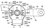
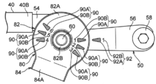
- This mark includes a first mark 90 (see FIG. 1A) formed on the water receiving member 80 and a second mark 92 (see FIGS. 1A and 8A) formed on the first pivot holder 20 and the second pivot holder 50, respectively. Reference).
- the first mark 90 is formed on a receiving surface that is visible from the front end side of the first pivot shaft 30 (second pivot shaft 60) in the receiving portion 82A of the water receiving member 80. Therefore, when the water receiving member 80 is assembled to the first pivot holder 20 and the second pivot holder 50, the first mark 90 is visible from the tip side of the first pivot shaft 30 (second pivot shaft 60). It is configured.
- the first mark 90 has a concave shape and is formed on the water receiving member 80 when the water receiving member 80 is molded. That is, a shape for the first mark 90 is formed in a mold for forming the water receiving member 80.
- first marks 90 are formed in the receiving portion 82A (six locations in the present embodiment). Specifically, three first marks 90 are formed on one side (one side in the longitudinal direction of the vehicle wiper device 10) with respect to the reference line CL in the receiving portion 82A. On the other hand, three first marks 90 are formed on the other side (the other side in the longitudinal direction of the vehicle wiper device 10) with respect to the reference line CL in the receiving portion 82A. Further, the first marks 90 are arranged at a predetermined angular interval in the circumferential direction of the first pivot shaft 30 (second pivot shaft 60).
- the three first marks 90 arranged on one side with respect to the reference line CL are marks for assembling the water receiving member 80 to the first pivot holder 20, and with respect to the reference line CL.
- the three first marks 90 arranged on the other side are marks for assembling the water receiving member 80 to the second pivot holder 50.
- the angular interval between the first marks 90 in the circumferential direction of the first pivot shaft 30 (second pivot shaft 60) is appropriately set according to the assembly posture of the water receiving member 80 corresponding to the wiper device of various vehicles. ing.
- the first mark 90 includes a first positioning mark 90 ⁇ / b> A serving as an index of a normal assembly posture (position) of the water receiving member 80 with respect to the first pivot holder 20 (second pivot holder 50), and a plurality of first marks 90.
- a first determination mark 90B for determining which mark is used is provided.
- the first positioning mark 90A is configured by a figure or the like. In the present embodiment, the first positioning mark 90A is configured by an isosceles triangle figure, and the first apex of the triangle is directed radially outward of the first pivot shaft 30 (second pivot shaft 60).
- One positioning mark 90A is arranged. In the above example, the case where the first positioning mark 90A is a figure is illustrated, but the first positioning mark 90A may be configured by an arrow, a line, or the like.
- the first discrimination mark 90B is disposed on the radially inner side of the first pivot shaft 30 (second pivot shaft 60) with respect to the first positioning mark 90A.
- the first discrimination mark 90B is composed of characters, numbers, etc. (in the present embodiment, the first discrimination mark 90B is composed of numbers). Different numbers are assigned to the plurality of first determination marks 90B. Specifically, numbers “4” to “6” are attached to the first discrimination mark 90B for assembly to the first pivot holder 20, and are for assembly to the second pivot holder 50. The numbers “1” to “3” are attached to the first discrimination marks 90B.
- the first mark 90 of the first determination mark 90 ⁇ / b> B marked with “5” is used for the water receiving member 80 assembled to the first pivot holder 20. (See FIG. 1A).
- the first mark 90 of the first discrimination mark 90B marked with “4” is set to be used.
- the wiper device of the vehicle in an assembled state in which the water receiving member 80 is rotated to the other circumferential side of the first pivot shaft 30 (the direction indicated by the arrow H in FIG. 1A)
- the first mark 90 of the first discrimination mark 90B marked with “6” is set to be used.
- the first mark 90 of 90B is used.
- the first mark 90 of the first discrimination mark 90B marked with “1” is set to be used (see FIG. 8C).
- the second mark 92 is formed on the fixed leg portion 26 of the first pivot holder 20 and the fixed leg portion 56 of the second pivot holder 50, respectively. . Since the second marks 92 formed on the fixed leg portion 26 and the fixed leg portion 56 have the same configuration, the second mark 92 formed on the fixed leg portion 26 will be described. The description of the second mark 92 formed on the portion 56 is omitted as appropriate.
- the second mark 92 is formed on the surface (upper surface) on the distal end side of the first pivot shaft 30 in the fixed leg portion 26. Further, the second mark 92 is disposed on the outer side in the radial direction of the first pivot shaft 30 than the water receiving member 80 in the assembled state of the water receiving member 80 to the first pivot holder 20. For this reason, when the water receiving member 80 is assembled to the first pivot holder 20, the second mark 92 is configured to be visible from the front end side of the first pivot shaft 30. Further, the second mark 92 has a concave shape and is formed when the first pivot holder 20 is molded. That is, a shape for the second mark 92 is formed in a mold for molding the first pivot holder 20.
- the second mark 92 includes a second positioning mark 92A and a second discrimination mark 92B.
- the second positioning mark 92 ⁇ / b> A is a mark that serves as an index of the normal assembly posture (position) of the water receiving member 80 with respect to the first pivot holder 20.
- the second discrimination mark 92B is a mark for discriminating which mark to use for the plurality of first marks 90 of the water receiving member 80 to be assembled.
- the second positioning mark 92 ⁇ / b> A is composed of the same figure as the first positioning mark 90 ⁇ / b> A of the first mark 90.
- the second positioning mark 92A is configured by an isosceles triangle figure, and the apex of the triangle faces the radially inner side of the first pivot shaft 30 (the first pivot shaft 30 side).
- the second positioning mark 92A is arranged.
- the second discrimination mark 92B is disposed on the radially outer side of the first pivot shaft 30 with respect to the second positioning mark 92A.
- the second discrimination mark 92B is composed of the same characters and numbers as the first discrimination mark 90B of the first mark 90. That is, in the present embodiment, the second discrimination mark 92B is composed of numerals.
- the number of the second discrimination mark 92B is the same as any one of the plurality of first discrimination marks 90B. That is, the second mark 92 is configured as a mark that is paired with any one of the plurality of first marks 90.
- the first pivot holder 20 and the second pivot holder 50 have a plurality of types. The direction in which the water receiving member 80 is attached to the first pivot holder 20 and the second pivot holder 50 is different for each of the plurality of types of the first pivot holder 20 and the second pivot holder 50.
- the second mark 92 includes a second determination mark 92B and a second positioning mark 92A corresponding to the types of the first pivot holder 20 and the second pivot holder 50.
- Each of the plurality of first marks 90 includes a first determination mark 90B and a first positioning mark 90A corresponding to a plurality of types of the first pivot holder 20 and the second pivot holder 50.
- the formation positions of the second determination mark 92B and the second positioning mark 92A of the second mark 92 and the plurality of first determination marks 90B and the first positioning mark 90A of the first mark 90 are determined according to the second mark 92.
- the second discrimination mark 92B and the first discrimination mark 90B of the first mark 90 correspond to each other, and the second positioning mark 92A of the second mark 92 and the first positioning mark 90A of the first mark 90 are the diameters of the pivot shafts 30 and 60.
- the water receiving member 80 is assembled to the first pivot holder 20 and the second pivot holder 50 so as to oppose each other, the water receiving member 80 is oriented in the direction corresponding to the type of the first pivot holder 20 and the second pivot holder 50. Is determined and arranged so that can be properly assembled.
- first mark 90 and the second mark 92 are formed in a concave shape, but the first mark 90 and the second mark 92 may be formed in a convex shape. Further, the first mark 90 and the second mark 92 may be formed by printing or engraving the water receiving member 80, the first pivot holder 20, and the second pivot holder 50, respectively.
- the operator when assembling the water receiving member 80 to the first pivot holder 20, the operator places the water receiving member 80 on the distal end side with respect to the first pivot shaft 30, and The cap part 82 ⁇ / b> B of the water receiving member 80 is arranged coaxially with the first pivot shaft 30.
- the operator discriminates the first mark 90 used in the water receiving member 80 and adjusts the posture (position) of the water receiving member 80 in the circumferential direction of the first pivot shaft 30.
- the operator determines the first mark 90 that is paired with the second mark 92 formed on the first pivot holder 20. That is, the operator discriminates the first discrimination mark 90B that is the same as the second discrimination mark 92B.
- the first mark 90 of the first discrimination mark 90B with “5” is attached. Is the mark used.
- the first positioning mark 90 ⁇ / b> A of the first mark 90 and the second positioning mark 92 ⁇ / b> A of the second mark 92 are used in the radial direction of the first pivot shaft 30.
- the operator adjusts the posture (position) of the water receiving member 80 in the circumferential direction of the first pivot shaft 30 so as to oppose each other.
- the operator moves the water receiving member 80 to the proximal end side of the first pivot shaft 30, so that the first pivot shaft 30 and the first pivot shaft 30 are moved to the first pivot shaft 30.
- the sleeve 22 of the pivot holder 20 is inserted into the cap portion 82 ⁇ / b> B of the water receiving member 80.
- the operator further moves the water receiving member 80 to the proximal end side of the first pivot shaft 30 and fits the engagement protrusion 88 into the recess 22B1 of the second engaged portion 22B of the first pivot holder 20.
- the engagement protrusion 88 is engaged with the second engaged portion 22B in the circumferential direction of the first pivot shaft 30.
- the worker fits the hook portion 86 ⁇ / b> A of the engaging claw portion 86 into the recess 22 ⁇ / b> A ⁇ b> 2 of the first engaged portion 22 ⁇ / b> A of the first pivot holder 20. Therefore, the engaging claw portion 86 is engaged with the first engaged portion 22A in the circumferential direction of the first pivot shaft 30, and is engaged with the first engaged portion 22A in the axial direction of the first pivot shaft 30. Is done.
- the water receiving member 80 is assembled to the first pivot holder 20 in a state where the movement of the water receiving member 80 in the circumferential direction is restricted and the movement of the water receiving member 80 toward the distal end side is restricted. .
- the discharge portion 84 of the water receiving member 80 is disposed on the front side of the first pivot shaft 30.
- the assembly posture of the water receiving member 80 may be different depending on various vehicles.
- the position of the discharge portion 84 of the water receiving member 80 is one side in the circumferential direction of the first pivot shaft 30 (the arrow G direction side in FIG. 1A) or the first pivot shaft 30 as compared to the present embodiment.
- the setting may be shifted to the other side in the circumferential direction (the arrow H direction side in FIG. 1A). For this reason, for example, as shown in FIG. 7A, when the position of the discharge portion 84 of the water receiving member 80 is set to be shifted to one side in the circumferential direction of the first pivot shaft 30 with respect to the present embodiment.
- the water receiving member 80 can be shared. In general, it is difficult to share the pivot holder because the length and shape of the fixed leg portion, the extending direction, and the like differ depending on various vehicles.
- the first mark 90 having the first discrimination mark 90B with the numeral “4” corresponding to the shift amount of the first engaged portion 22A and the second engaged portion 22B is the water receiving member 80. Is formed.
- a second mark 92 having a second discrimination mark 92 ⁇ / b> B identical to the numeral “4” is formed on the first pivot holder 20.
- the first positioning mark 90A of the first mark 90 to be used and the second positioning mark 92A of the second mark 92 are opposed to each other in the radial direction of the first pivot shaft 30 in the same manner as the assembly procedure described above.
- the water receiving member 80 can be attached to the first pivot holder 20. Can be assembled to.
- the first engaged member By shifting the positions of the joint portion 22A and the second engaged portion 22B to the other circumferential side of the first pivot shaft 30 with respect to the present embodiment, the first engaged member By shifting the positions of the joint portion 22A and the second engaged portion 22B to the other circumferential side of the first pivot shaft 30, the water receiving member 80 can be shared. Further, in this case, similarly to the above, the first determination mark 90B with the numeral “6” is provided corresponding to the shift amount of the first engaged portion 22A and the second engaged portion 22B. A first mark 90 is formed on the water receiving member 80. Further, a second mark 92 having a second discrimination mark 92B identical to the numeral “6” is formed on the first pivot holder 20. And the water receiving member 80 can be assembled
- the water receiving member 80 is assembled to the second pivot holder 50, the water receiving member 80 is assembled in the same manner as the procedure for assembling the water receiving member 80 to the first pivot holder 20. That is, as shown in FIG. 8A, in the present embodiment, the second determination mark 92B and the first determination mark 90B with the numeral “2” are the same.
- the first mark 90 of the first discrimination mark 90B marked with “2” is a mark to be used.
- the operator then moves the second positioning mark 90 ⁇ / b> A of the first mark 90 and the second positioning mark 92 ⁇ / b> A of the second mark 92 to face each other in the radial direction of the second pivot shaft 60.
- the water receiving member 80 is assembled to the second pivot holder 50 while adjusting the posture of the water receiving member 80 in the circumferential direction of the pivot shaft 60.
- the position of the discharge portion 84 of the water receiving member 80 relative to the second pivot holder 50 is the circumferential direction of the second pivot shaft 60 with respect to the present embodiment.
- the positions of the first engaged portion and the second engaged portion of the second pivot holder 50 are shifted to the other side in the circumferential direction of the second pivot shaft 60, thereby
- the receiving member 80 can be shared.
- the first mark 90 having the first discrimination mark 90B with the numeral “3” corresponding to the shift amount of the first engaged portion and the second engaged portion is the water.
- the receiving member 80 is formed.
- a second mark 92 having a second discrimination mark 92 ⁇ / b> B that matches the numeral “3” is formed on the second pivot holder 50.
- the operator then moves the second positioning mark 90 ⁇ / b> A of the first mark 90 and the second positioning mark 92 ⁇ / b> A of the second mark 92 to face each other in the radial direction of the second pivot shaft 60.
- the water receiving member 80 is assembled to the second pivot holder 50 while adjusting the posture of the water receiving member 80 in the circumferential direction of the pivot shaft 60.
- the position of the discharge portion 84 of the water receiving member 80 with respect to the second pivot holder 50 is the circumferential direction of the second pivot shaft 60 with respect to the present embodiment.
- the positions of the first engaged portion and the second engaged portion of the second pivot holder 50 are shifted to one side in the circumferential direction of the second pivot shaft 60, thereby
- the receiving member 80 can be shared.
- the first mark 90 having the first discrimination mark 90B with the numeral “1” corresponding to the shift amount of the first engaged portion and the second engaged portion is the water.
- the receiving member 80 is formed.
- a second mark 92 having a second discrimination mark 92 ⁇ / b> B that matches the numeral “1” is formed on the second pivot holder 50.
- the operator then moves the second positioning mark 90 ⁇ / b> A of the first mark 90 and the second positioning mark 92 ⁇ / b> A of the second mark 92 to face each other in the radial direction of the second pivot shaft 60.
- the water receiving member 80 is assembled to the second pivot holder 50 while adjusting the posture of the water receiving member 80 in the circumferential direction of the pivot shaft 60.
- the first mark 90 serving as a mark for assembling the water receiving member 80 to the first pivot holder 20 (second pivot holder 50).
- the first pivot holder 20 (second pivot holder 50) includes a second water receiving member 80 at a position radially outside the first pivot shaft 30 (second pivot shaft 60) with respect to the water receiving member 80.
- a second mark 92 is formed which serves as an index of a normal assembly posture to the first pivot holder 20 (second pivot holder 50). The second mark 92 is paired with any one of the plurality of first marks 90.
- the first mark 90 is aligned with the second mark 92 that forms a pair, and the water receiving member 80 is assembled to the first pivot holder 20 (second pivot holder 50), so that the water receiving member 80 is placed in the normal position. Can be assembled to. Accordingly, even when the water receiving member 80 shared with the wiper device of various vehicles is used, the water receiving member 80 is prevented from being assembled erroneously, and the water receiving member 80 is attached to the first pivot holder 20 (second It can be assembled to the pivot holder 50).
- the water receiving member 80 is formed with a plurality of first marks 90 on one side of the reference line CL, and a plurality of first marks on the other side of the reference line CL. 90 is formed. Therefore, the water receiving member 80 used for the first pivot shaft 30 and the second pivot shaft 60 is shared, and the shared water receiving member 80 has the first pivot shaft 30 and the second pivot shaft 60. Can be prevented.
- first mark 90 is formed on the receiving surface of the receiving portion 82A of the water receiving member 80.
- the second mark 92 is formed on the upper surface of the first pivot shaft 30 (second pivot shaft 60) in the fixed leg portion 26 (fixed leg portion 56) of the first pivot holder 20 (second pivot holder 50).
- first pivot shaft 30 (second pivot shaft 60) is disposed radially outside the water receiving member 80. For this reason, when the water receiving member 80 is assembled to the first pivot holder 20 (second pivot holder 50), the first mark 90 and the second mark 92 become visible. Thereby, the assembly
- an engaging claw portion 86 is integrally formed at a boundary portion between the receiving portion 82A and the slope portion 84A, and the engaging claw portion 86 is connected to the base of the first pivot shaft 30 from the receiving portion 82A. It protrudes to the end side. For this reason, since slope 84A of discharge part 84 is reinforced by engagement claw part 86, rigidity of discharge part 84 can be made high. Thereby, for example, the discharge portion 84 can be prevented from falling toward the distal end side of the first pivot shaft 30 (second pivot shaft 60).
- a plurality of first marks 90 are formed on both sides of the receiving portion 82A of the water receiving member 80 with respect to the reference line CL.
- a plurality of first marks 90 may be formed on one or the other side of the receiving portion 82A of the water receiving member 80 with respect to the reference line CL.
- the water receiving member 80 can be shared with the first pivot holder 20 in the wiper device of various vehicles, and erroneous assembly of the water receiving member 80 to the first pivot holder 20 is prevented. be able to.
- the water receiving member 80 can be shared with the second pivot holder 50 in the wiper device of various vehicles, and erroneous assembly of the water receiving member 80 to the second pivot holder 50 can be prevented. .
- a plurality of first marks 90 are formed on both sides of the receiving portion 82A of the water receiving member 80 with respect to the reference line CL.
- a single first mark 90 may be formed on both sides of the water receiving member 80 with respect to the reference line in the receiving portion 82A.
- the water receiving member 80 is used while the water receiving member 80 assembled to the first pivot holder 20 and the water receiving member 80 assembled to the second pivot holder 50 are shared. Can be prevented.
Landscapes
- Engineering & Computer Science (AREA)
- Mechanical Engineering (AREA)
- Transmission Devices (AREA)
- Body Structure For Vehicles (AREA)
- Vehicle Cleaning, Maintenance, Repair, Refitting, And Outriggers (AREA)
- Pivots And Pivotal Connections (AREA)
Abstract
Description
第1ピボットホルダ20は、車両用ワイパ装置10の長手方向一方側(図2及び図3の矢印A方向側)に設けられている。この第1ピボットホルダ20は、アルミニウム合金によるダイカスト成形等で製作されている。また、図4及び図5にも示されるように、第1ピボットホルダ20は、後述する第1ピボット軸30を回転自在に支持するスリーブ22(広義には、「支持部」として把握される要素である)を有しており、スリーブ22は略円筒状に形成されている。
図4及び図5に示されるように、第1ピボット軸30は、スリーブ22内に挿入されて、スリーブ22に回転自在に支持されている。この第1ピボット軸30の先端部(図4及び図5の矢印E方向側の端部)には、ワイパアーム(図示省略)の基端部が固定されており、ワイパアームの先端部には、図示しないワイパブレードが連結されている。一方、第1ピボット軸30の基端部には、第1ピボット軸30の径方向外側へ延出する第1レバー32が固定されている。そして、第1レバー32が第1ピボット軸30の軸回りに回転することで、第1ピボット軸30と共にワイパアームが第1ピボット軸30の軸回りに回転して、ワイパブレードが、車両のフロントウィンドシールドガラスを払拭するようになっている。なお、第1ピボット軸30は、車両の上下方向に対して前側へ傾倒するように傾いている。
図2及び図3に示されるように、中空フレーム40は、長尺状を成す中空のパイプ材により製作されて、第1ピボットホルダ20の連結部24と同軸上に配置されている。この中空フレーム40の長手方向一端部は、第1固定部40Aとされている。そして、第1固定部40A内に第1ピボットホルダ20の連結部24が嵌入されており、第1固定部40Aが連結部24にカシメ加工等によって固定されている。一方、中空フレーム40の長手方向他端部は、第2固定部40Bとされており、第2固定部40Bは、後述する第2ピボットホルダ50にカシメ加工等によって固定されている。
第2ピボットホルダ50は、車両用ワイパ装置10の長手方向他方側(図2及び図3の矢印B方向側)に設けられている。第2ピボットホルダ50は、第1ピボットホルダ20と同様にアルミニウム合金によるダイカスト成形等で製作されている。また、第2ピボットホルダ50は、円筒状のスリーブ52(広義には、「支持部」として把握される要素である)を有しており、スリーブ52(図3参照)は、第1ピボットホルダ20のスリーブ22と略平行に配置されている。
図3に示されるように、第2ピボット軸60は、スリーブ52内に挿入されて、スリーブ52に回転自在に支持されている。この第2ピボット軸60の先端部には、ワイパアーム(図示省略)の基端部が固定されており、ワイパアームの先端部には、図示しないワイパブレードが連結されている。一方、第2ピボット軸60の基端部には、第2ピボット軸60の径方向外側へ延出する第2レバー62が固定されている。そして、第2レバー62が第2ピボット軸60の軸回りに回転することで、第2ピボット軸60と共にワイパアームが第2ピボット軸60の軸回りに回転して、ワイパブレードがフロントウィンドシールドガラスを払拭するようになっている。
図3に示されるように、ワイパモータ70は、前述したブラケット42に対して第1ピボット軸30の軸方向一方側に配置されて、ネジ等の締結部材によってブラケット42に締結固定されている。また、ワイパモータ70は、ワイパモータ70の駆動力を出力するための出力軸(図示省略)を有しており、出力軸の先端部にクランクアーム72が固定されている。そして、ワイパモータ70の作動時には、クランクアーム72が出力軸の軸回りに回転するようになっている。
図2及び図3に示されるように、リンク機構74は、ワイパモータ70の駆動力を第1ピボット軸30及び第2ピボット軸60へ伝達するための機構とされている。このリンク機構74は第1リンクロッド76を有しており、第1リンクロッド76は、略長尺状のパイプ材によって製作されている。そして、第1リンクロッド76の長手方向一端部が、ボールジョイント77Aによって第1レバー32の先端部に転動可能に駆動連結され、第1リンクロッド76の長手方向他端部が、ボールジョイント77B(図3参照)によってクランクアーム72に転動可能に駆動連結されている。これにより、ワイパモータ70と第1ピボット軸30とが第1リンクロッド76によって連結されて、ワイパモータ70の駆動力が第1ピボット軸30へ伝達されるようになっている。
図2及び図3に示されるように、水受部材80は、第1ピボットホルダ20及び第2ピボットホルダ50にそれぞれ組付けられている。そして、水受部材80の第1ピボットホルダ20及び第2ピボットホルダ50への組付構造は同様に構成されている。このため、以下、第1ピボットホルダ20に組付けられる水受部材80を用いて、水受部材80の構成について説明する。
上記のように、第1ピボットホルダ20及び第2ピボットホルダ50は、複数の種類がある。水受部材80が第1ピボットホルダ20及び第2ピボットホルダ50に取り付ける方向は、第1ピボットホルダ20及び第2ピボットホルダ50の複数の種類の各々について異なる。第2マーク92は、第1ピボットホルダ20及び第2ピボットホルダ50の種類に応じた第2判別マーク92B及び第2位置決めマーク92Aを有する。複数の第1マーク90の各々は、第1ピボットホルダ20及び第2ピボットホルダ50の複数の種類に応じた第1判別マーク90B及び第1位置決めマーク90Aを有する。第2マーク92の第2判別マーク92B及び第2位置決めマーク92Aと、第1マーク90の複数の第1判別マーク90B及び第1位置決めマーク90Aとの各々の形成位置は、第2マーク92の第2判別マーク92Bと第1マーク90の第1判別マーク90Bとが対応し且つ第2マーク92の第2位置決めマーク92Aと第1マーク90の第1位置決めマーク90Aとがピボット軸30、60の径方向に対向するように、水受部材80が第1ピボットホルダ20及び第2ピボットホルダ50に組み付けられると、第1ピボットホルダ20及び第2ピボットホルダ50の種類に応じた方向に水受部材80が適正に組み付けられるように、決定されて配置されている。
本明細書に記載された全ての文献、特許出願、及び技術規格は、個々の文献、特許出願、及び技術規格が参照により取り込まれることが具体的にかつ個々に記載された場合と同様に、本明細書中に参照により取り込まれる。
Claims (8)
- ワイパモータの駆動力によって回転されるピボット軸と、
前記ピボット軸を回転自在に支持するピボットホルダと、
前記ピボットホルダに組付けられており、前記ピボット軸の径方向外側に配置された水受け部と、前記水受け部の所定位置から前記ピボット軸の径方向外側へ延出され且つ前記水受け部によって受けた液体を排出する排出部と、を含んで構成された水受部材と、
を備え、
前記水受部材には、前記水受部材の前記ピボットホルダへの組付用の目印となる第1マークが複数形成されており、
前記ピボットホルダには、複数の前記第1マークの少なくとも何れか1つと対を成し且つ前記水受部材の前記ピボットホルダへの正規の組付姿勢の指標となる第2マークが形成されている車両用ワイパ装置。 - 前記ピボット軸の先端側から見て、前記ピボット軸の軸線を通過し且つ前記排出部の延出方向に延びる基準線に対して片側に、複数の前記第1マークが形成されている請求項1に記載の車両用ワイパ装置。
- 前記ピボット軸は、前記ワイパモータの駆動力がリンク機構を介して伝達されて回転される第1ピボット軸及び第2ピボット軸を含んで構成され、
前記ピボットホルダは、前記第1ピボット軸を回転自在に支持する第1ピボットホルダと、前記第2ピボット軸を回転自在に支持する第2ピボットホルダと、を有しており、
前記ピボット軸の先端側から見て、前記ピボット軸の軸線を通過し且つ前記排出部の延出方向に延びる基準線に対して両側に、複数の前記第1マークが、それぞれ形成され、
前記第1ピボットホルダ及び前記第2ピボットホルダには、前記第2マークがそれぞれ形成されている請求項1に記載の車両用ワイパ装置。 - 前記第1マーク及び前記第2マークが、前記ピボット軸の先端側から見て、視認可能に配置されている請求項1~請求項3の何れか1項に記載の車両用ワイパ装置。
- 前記水受部材は、
前記水受け部から前記ピボット軸の基端側へ突出され、前記ピボットホルダとの周方向の係合状態において前記水受部材の周方向への移動を制限する係合突起と、
前記水受け部から前記ピボット軸の基端側へ突出され、前記ピボットホルダとの軸方向の係合状態において前記水受部材の先端側への移動を制限する係合爪部と、
を備え、
前記ピボット軸の軸方向から見て、前記係合爪部が前記ピボット軸に対して前記排出部側に配置され、前記係合突起が前記ピボット軸に対して前記排出部とは反対側に配置されている請求項1~請求項4の何れか1項に記載の車両用ワイパ装置。 - 前記ピボットホルダは、複数の種類があり、
前記水受部材が前記ピボットホルダに取り付ける方向は、前記ピボットホルダの前記複数の種類の各々について異なり、
前記第2マークは、前記ピボットホルダの種類に応じた判別マーク及び位置決めマークを有し、
複数の前記第1マークの各々は、前記ピボットホルダの前記複数の種類に応じた判別マーク及び位置決めマークを有し、
前記第2マークの前記判別マーク及び前記位置決めマークと、複数の前記第1マークの各々の前記判別マーク及び前記位置決めマークとは、前記第2マークの前記判別マークと前記第1マークの前記判別マークとが対応し且つ前記第2マークの前記位置決めマークと前記第1マークの前記位置決めマークとが前記ピボット軸の径方向に対向するように、前記水受部材が前記ピボットホルダに組み付けられると、前記ピボットホルダの種類に応じた方向に前記水受部材が組み付けられるように、配置される、
請求項1~請求項5の何れか1項に記載の車両用ワイパ装置。 - 前記水受部材には、前記ピボット軸の先端側から見て視認可な受面を有する受部を有し、
前記第1マークは、前記受面に形成される、
請求項4~請求項6の何れか1項に記載の車両用ワイパ装置。 - 前記ピボットホルダは、前記係合突起が係合される第1被係合部及び前記係合爪部が係合される第2被係合部が形成され且つ前記ピボット軸を支持するスリーブを有する、請求項5~請求項7の何れか1項に記載の車両用ワイパ装置。
Priority Applications (4)
| Application Number | Priority Date | Filing Date | Title |
|---|---|---|---|
| KR1020187019349A KR102017439B1 (ko) | 2015-12-16 | 2016-11-30 | 차량용 와이퍼 장치 |
| US16/060,420 US10780862B2 (en) | 2015-12-16 | 2016-11-30 | Vehicle wiper device |
| DE112016005817.9T DE112016005817B4 (de) | 2015-12-16 | 2016-11-30 | Fahrzeugwischervorrichtung |
| CN201680073558.XA CN108473112B (zh) | 2015-12-16 | 2016-11-30 | 车辆用刮水器装置 |
Applications Claiming Priority (2)
| Application Number | Priority Date | Filing Date | Title |
|---|---|---|---|
| JP2015-245416 | 2015-12-16 | ||
| JP2015245416A JP6572763B2 (ja) | 2015-12-16 | 2015-12-16 | 車両用ワイパ装置 |
Publications (1)
| Publication Number | Publication Date |
|---|---|
| WO2017104419A1 true WO2017104419A1 (ja) | 2017-06-22 |
Family
ID=59056383
Family Applications (1)
| Application Number | Title | Priority Date | Filing Date |
|---|---|---|---|
| PCT/JP2016/085636 Ceased WO2017104419A1 (ja) | 2015-12-16 | 2016-11-30 | 車両用ワイパ装置 |
Country Status (6)
| Country | Link |
|---|---|
| US (1) | US10780862B2 (ja) |
| JP (1) | JP6572763B2 (ja) |
| KR (1) | KR102017439B1 (ja) |
| CN (1) | CN108473112B (ja) |
| DE (1) | DE112016005817B4 (ja) |
| WO (1) | WO2017104419A1 (ja) |
Families Citing this family (2)
| Publication number | Priority date | Publication date | Assignee | Title |
|---|---|---|---|---|
| JP6572763B2 (ja) | 2015-12-16 | 2019-09-11 | 株式会社デンソー | 車両用ワイパ装置 |
| US12330597B2 (en) | 2023-10-13 | 2025-06-17 | Valeo Systemes D'essuyage | Pivot assembly for a wiper system |
Citations (8)
| Publication number | Priority date | Publication date | Assignee | Title |
|---|---|---|---|---|
| JP2002127874A (ja) * | 2000-10-19 | 2002-05-09 | Asmo Co Ltd | ワイパピボットの防水構造及び防水キャップ |
| JP2003118542A (ja) * | 2001-10-09 | 2003-04-23 | Asmo Co Ltd | 車両用ワイパピボット |
| JP2005324710A (ja) * | 2004-05-14 | 2005-11-24 | Asmo Co Ltd | ワイパピボットおよびモジュール型ワイパ装置 |
| JP2007223561A (ja) * | 2006-02-27 | 2007-09-06 | Mitsuba Corp | ワイパ装置 |
| JP2007320465A (ja) * | 2006-06-02 | 2007-12-13 | Mazda Motor Corp | 自動車の前部構造 |
| JP2011183851A (ja) * | 2010-03-04 | 2011-09-22 | Asmo Co Ltd | ワイパ装置 |
| JP2012006543A (ja) * | 2010-06-28 | 2012-01-12 | Suzuki Motor Corp | ワイパー装置のボルト保持構造 |
| FR2965232A1 (fr) * | 2010-09-29 | 2012-03-30 | Valeo Systemes Dessuyage | Support d'un groupe electrique d'entrainement d'un systeme d'essuyage |
Family Cites Families (10)
| Publication number | Priority date | Publication date | Assignee | Title |
|---|---|---|---|---|
| JPH02245416A (ja) | 1989-03-20 | 1990-10-01 | Hitachi Ltd | 熱交換器出口の流体温度制御装置 |
| JP3982745B2 (ja) * | 2002-02-20 | 2007-09-26 | 自動車電機工業株式会社 | ワイパピボット装置の防水構造 |
| JP3934509B2 (ja) * | 2002-08-22 | 2007-06-20 | アスモ株式会社 | 防水キャップとピボットホルダとの固定構造及びモジュール型ワイパ装置 |
| KR100681070B1 (ko) * | 2004-07-09 | 2007-02-08 | 현대자동차주식회사 | 자동차용 와이퍼 장치 |
| JP2007196959A (ja) * | 2006-01-30 | 2007-08-09 | Mitsuba Corp | 車両用ワイパ装置 |
| CN201784581U (zh) * | 2010-09-16 | 2011-04-06 | 北汽福田汽车股份有限公司 | 车辆雨刮器及车辆 |
| JP2015105025A (ja) | 2013-11-29 | 2015-06-08 | アスモ株式会社 | モジュール型ワイパ装置 |
| CN203793287U (zh) * | 2014-04-14 | 2014-08-27 | 成都华川电装有限责任公司 | 雨刮器防水安装座 |
| CN203996117U (zh) * | 2014-07-31 | 2014-12-10 | 重庆长安汽车股份有限公司 | 一种汽车刮水器传动臂防水结构 |
| JP6572763B2 (ja) | 2015-12-16 | 2019-09-11 | 株式会社デンソー | 車両用ワイパ装置 |
-
2015
- 2015-12-16 JP JP2015245416A patent/JP6572763B2/ja active Active
-
2016
- 2016-11-30 US US16/060,420 patent/US10780862B2/en active Active
- 2016-11-30 KR KR1020187019349A patent/KR102017439B1/ko active Active
- 2016-11-30 CN CN201680073558.XA patent/CN108473112B/zh active Active
- 2016-11-30 DE DE112016005817.9T patent/DE112016005817B4/de active Active
- 2016-11-30 WO PCT/JP2016/085636 patent/WO2017104419A1/ja not_active Ceased
Patent Citations (8)
| Publication number | Priority date | Publication date | Assignee | Title |
|---|---|---|---|---|
| JP2002127874A (ja) * | 2000-10-19 | 2002-05-09 | Asmo Co Ltd | ワイパピボットの防水構造及び防水キャップ |
| JP2003118542A (ja) * | 2001-10-09 | 2003-04-23 | Asmo Co Ltd | 車両用ワイパピボット |
| JP2005324710A (ja) * | 2004-05-14 | 2005-11-24 | Asmo Co Ltd | ワイパピボットおよびモジュール型ワイパ装置 |
| JP2007223561A (ja) * | 2006-02-27 | 2007-09-06 | Mitsuba Corp | ワイパ装置 |
| JP2007320465A (ja) * | 2006-06-02 | 2007-12-13 | Mazda Motor Corp | 自動車の前部構造 |
| JP2011183851A (ja) * | 2010-03-04 | 2011-09-22 | Asmo Co Ltd | ワイパ装置 |
| JP2012006543A (ja) * | 2010-06-28 | 2012-01-12 | Suzuki Motor Corp | ワイパー装置のボルト保持構造 |
| FR2965232A1 (fr) * | 2010-09-29 | 2012-03-30 | Valeo Systemes Dessuyage | Support d'un groupe electrique d'entrainement d'un systeme d'essuyage |
Also Published As
| Publication number | Publication date |
|---|---|
| JP6572763B2 (ja) | 2019-09-11 |
| DE112016005817T5 (de) | 2018-08-30 |
| KR20180090872A (ko) | 2018-08-13 |
| KR102017439B1 (ko) | 2019-09-02 |
| CN108473112A (zh) | 2018-08-31 |
| DE112016005817B4 (de) | 2024-06-06 |
| US20190001928A1 (en) | 2019-01-03 |
| JP2017109610A (ja) | 2017-06-22 |
| US10780862B2 (en) | 2020-09-22 |
| CN108473112B (zh) | 2020-12-08 |
Similar Documents
| Publication | Publication Date | Title |
|---|---|---|
| US10676030B2 (en) | Vehicle exterior camera device | |
| EP3452341B1 (en) | Vehicle provided with at least two windscreen wiper devices of the flat blade type | |
| EP2471693B1 (en) | Multi-adapter for a vehicle wiper | |
| JP4038798B2 (ja) | 車両用ワイパ | |
| KR20050042063A (ko) | 차량의 방풍유리용 와이퍼 장치 | |
| CN204488683U (zh) | 支架和车辆 | |
| JP2006007971A (ja) | ワイパ装置 | |
| JP6572763B2 (ja) | 車両用ワイパ装置 | |
| US9090231B2 (en) | Wiper blade apparatus including fool-proof assembly structure | |
| JP4795053B2 (ja) | ワイパ装置 | |
| JP6348334B2 (ja) | ワイパブレードの連結構造 | |
| US10676029B2 (en) | Viewing device for vehicle | |
| US20240116446A1 (en) | Vehicular camera unit | |
| JP6309646B2 (ja) | 自動車のフロントエンドキャリア上のラジエータカウリング及びバンパの取り付け装置 | |
| JP2010064702A (ja) | カウルルーバ構造 | |
| US10293754B2 (en) | Mirror device for vehicle | |
| JP2010048367A (ja) | ボールジョイント構造及びワイパアーム | |
| US11738695B2 (en) | Externally mounted component of a motor vehicle | |
| US7510286B2 (en) | Exterior rearview mirror for vehicles, preferably for motor vehicles | |
| US20230032508A1 (en) | Adapter for a wiper blade of a vehicle | |
| JP3147654U (ja) | ウォッシャーノズルと噴射角度調整治具 | |
| JP6665672B2 (ja) | 車両用ワイパ | |
| JPS635134Y2 (ja) | ||
| JP2002370623A (ja) | ワイパーピボット部の構造 | |
| CN114379512A (zh) | 用于清洁具有高曲率的车辆车窗的雨刮器系统 |
Legal Events
| Date | Code | Title | Description |
|---|---|---|---|
| 121 | Ep: the epo has been informed by wipo that ep was designated in this application |
Ref document number: 16875403 Country of ref document: EP Kind code of ref document: A1 |
|
| WWE | Wipo information: entry into national phase |
Ref document number: 112016005817 Country of ref document: DE |
|
| ENP | Entry into the national phase |
Ref document number: 20187019349 Country of ref document: KR Kind code of ref document: A |
|
| WWE | Wipo information: entry into national phase |
Ref document number: 1020187019349 Country of ref document: KR |
|
| 122 | Ep: pct application non-entry in european phase |
Ref document number: 16875403 Country of ref document: EP Kind code of ref document: A1 |