WO2017104353A1 - タンク蓋ユニット及び燃料供給装置 - Google Patents
タンク蓋ユニット及び燃料供給装置 Download PDFInfo
- Publication number
- WO2017104353A1 WO2017104353A1 PCT/JP2016/084441 JP2016084441W WO2017104353A1 WO 2017104353 A1 WO2017104353 A1 WO 2017104353A1 JP 2016084441 W JP2016084441 W JP 2016084441W WO 2017104353 A1 WO2017104353 A1 WO 2017104353A1
- Authority
- WO
- WIPO (PCT)
- Prior art keywords
- metal terminal
- drive circuit
- fuel
- exposed
- tank
- Prior art date
- Legal status (The legal status is an assumption and is not a legal conclusion. Google has not performed a legal analysis and makes no representation as to the accuracy of the status listed.)
- Ceased
Links
Images





Classifications
-
- B—PERFORMING OPERATIONS; TRANSPORTING
- B60—VEHICLES IN GENERAL
- B60K—ARRANGEMENT OR MOUNTING OF PROPULSION UNITS OR OF TRANSMISSIONS IN VEHICLES; ARRANGEMENT OR MOUNTING OF PLURAL DIVERSE PRIME-MOVERS IN VEHICLES; AUXILIARY DRIVES FOR VEHICLES; INSTRUMENTATION OR DASHBOARDS FOR VEHICLES; ARRANGEMENTS IN CONNECTION WITH COOLING, AIR INTAKE, GAS EXHAUST OR FUEL SUPPLY OF PROPULSION UNITS IN VEHICLES
- B60K15/00—Arrangement in connection with fuel supply of combustion engines or other fuel consuming energy converters, e.g. fuel cells; Mounting or construction of fuel tanks
- B60K15/03—Fuel tanks
- B60K15/04—Tank inlets
- B60K15/05—Inlet covers
-
- B—PERFORMING OPERATIONS; TRANSPORTING
- B60—VEHICLES IN GENERAL
- B60K—ARRANGEMENT OR MOUNTING OF PROPULSION UNITS OR OF TRANSMISSIONS IN VEHICLES; ARRANGEMENT OR MOUNTING OF PLURAL DIVERSE PRIME-MOVERS IN VEHICLES; AUXILIARY DRIVES FOR VEHICLES; INSTRUMENTATION OR DASHBOARDS FOR VEHICLES; ARRANGEMENTS IN CONNECTION WITH COOLING, AIR INTAKE, GAS EXHAUST OR FUEL SUPPLY OF PROPULSION UNITS IN VEHICLES
- B60K15/00—Arrangement in connection with fuel supply of combustion engines or other fuel consuming energy converters, e.g. fuel cells; Mounting or construction of fuel tanks
- B60K15/03—Fuel tanks
-
- F—MECHANICAL ENGINEERING; LIGHTING; HEATING; WEAPONS; BLASTING
- F02—COMBUSTION ENGINES; HOT-GAS OR COMBUSTION-PRODUCT ENGINE PLANTS
- F02M—SUPPLYING COMBUSTION ENGINES IN GENERAL WITH COMBUSTIBLE MIXTURES OR CONSTITUENTS THEREOF
- F02M37/00—Apparatus or systems for feeding liquid fuel from storage containers to carburettors or fuel-injection apparatus; Arrangements for purifying liquid fuel specially adapted for, or arranged on, internal-combustion engines
- F02M37/04—Feeding by means of driven pumps
- F02M37/08—Feeding by means of driven pumps electrically driven
- F02M37/10—Feeding by means of driven pumps electrically driven submerged in fuel, e.g. in reservoir
-
- F—MECHANICAL ENGINEERING; LIGHTING; HEATING; WEAPONS; BLASTING
- F02—COMBUSTION ENGINES; HOT-GAS OR COMBUSTION-PRODUCT ENGINE PLANTS
- F02D—CONTROLLING COMBUSTION ENGINES
- F02D33/00—Controlling delivery of fuel or combustion-air, not otherwise provided for
- F02D33/003—Controlling the feeding of liquid fuel from storage containers to carburettors or fuel-injection apparatus ; Failure or leakage prevention; Diagnosis or detection of failure; Arrangement of sensors in the fuel system; Electric wiring; Electrostatic discharge
-
- F—MECHANICAL ENGINEERING; LIGHTING; HEATING; WEAPONS; BLASTING
- F02—COMBUSTION ENGINES; HOT-GAS OR COMBUSTION-PRODUCT ENGINE PLANTS
- F02M—SUPPLYING COMBUSTION ENGINES IN GENERAL WITH COMBUSTIBLE MIXTURES OR CONSTITUENTS THEREOF
- F02M37/00—Apparatus or systems for feeding liquid fuel from storage containers to carburettors or fuel-injection apparatus; Arrangements for purifying liquid fuel specially adapted for, or arranged on, internal-combustion engines
- F02M37/04—Feeding by means of driven pumps
- F02M37/08—Feeding by means of driven pumps electrically driven
-
- F—MECHANICAL ENGINEERING; LIGHTING; HEATING; WEAPONS; BLASTING
- F02—COMBUSTION ENGINES; HOT-GAS OR COMBUSTION-PRODUCT ENGINE PLANTS
- F02M—SUPPLYING COMBUSTION ENGINES IN GENERAL WITH COMBUSTIBLE MIXTURES OR CONSTITUENTS THEREOF
- F02M37/00—Apparatus or systems for feeding liquid fuel from storage containers to carburettors or fuel-injection apparatus; Arrangements for purifying liquid fuel specially adapted for, or arranged on, internal-combustion engines
- F02M37/04—Feeding by means of driven pumps
- F02M37/08—Feeding by means of driven pumps electrically driven
- F02M37/10—Feeding by means of driven pumps electrically driven submerged in fuel, e.g. in reservoir
- F02M37/103—Mounting pumps on fuel tanks
-
- F—MECHANICAL ENGINEERING; LIGHTING; HEATING; WEAPONS; BLASTING
- F02—COMBUSTION ENGINES; HOT-GAS OR COMBUSTION-PRODUCT ENGINE PLANTS
- F02M—SUPPLYING COMBUSTION ENGINES IN GENERAL WITH COMBUSTIBLE MIXTURES OR CONSTITUENTS THEREOF
- F02M37/00—Apparatus or systems for feeding liquid fuel from storage containers to carburettors or fuel-injection apparatus; Arrangements for purifying liquid fuel specially adapted for, or arranged on, internal-combustion engines
- F02M37/04—Feeding by means of driven pumps
- F02M37/14—Feeding by means of driven pumps the pumps being combined with other apparatus
-
- F—MECHANICAL ENGINEERING; LIGHTING; HEATING; WEAPONS; BLASTING
- F02—COMBUSTION ENGINES; HOT-GAS OR COMBUSTION-PRODUCT ENGINE PLANTS
- F02M—SUPPLYING COMBUSTION ENGINES IN GENERAL WITH COMBUSTIBLE MIXTURES OR CONSTITUENTS THEREOF
- F02M37/00—Apparatus or systems for feeding liquid fuel from storage containers to carburettors or fuel-injection apparatus; Arrangements for purifying liquid fuel specially adapted for, or arranged on, internal-combustion engines
- F02M37/22—Arrangements for purifying liquid fuel specially adapted for, or arranged on, internal-combustion engines, e.g. arrangements in the feeding system
- F02M37/30—Arrangements for purifying liquid fuel specially adapted for, or arranged on, internal-combustion engines, e.g. arrangements in the feeding system characterised by heating means
-
- B—PERFORMING OPERATIONS; TRANSPORTING
- B60—VEHICLES IN GENERAL
- B60K—ARRANGEMENT OR MOUNTING OF PROPULSION UNITS OR OF TRANSMISSIONS IN VEHICLES; ARRANGEMENT OR MOUNTING OF PLURAL DIVERSE PRIME-MOVERS IN VEHICLES; AUXILIARY DRIVES FOR VEHICLES; INSTRUMENTATION OR DASHBOARDS FOR VEHICLES; ARRANGEMENTS IN CONNECTION WITH COOLING, AIR INTAKE, GAS EXHAUST OR FUEL SUPPLY OF PROPULSION UNITS IN VEHICLES
- B60K15/00—Arrangement in connection with fuel supply of combustion engines or other fuel consuming energy converters, e.g. fuel cells; Mounting or construction of fuel tanks
- B60K15/03—Fuel tanks
- B60K2015/03243—Fuel tanks characterised by special pumps, the mounting thereof
-
- B—PERFORMING OPERATIONS; TRANSPORTING
- B60—VEHICLES IN GENERAL
- B60K—ARRANGEMENT OR MOUNTING OF PROPULSION UNITS OR OF TRANSMISSIONS IN VEHICLES; ARRANGEMENT OR MOUNTING OF PLURAL DIVERSE PRIME-MOVERS IN VEHICLES; AUXILIARY DRIVES FOR VEHICLES; INSTRUMENTATION OR DASHBOARDS FOR VEHICLES; ARRANGEMENTS IN CONNECTION WITH COOLING, AIR INTAKE, GAS EXHAUST OR FUEL SUPPLY OF PROPULSION UNITS IN VEHICLES
- B60K15/00—Arrangement in connection with fuel supply of combustion engines or other fuel consuming energy converters, e.g. fuel cells; Mounting or construction of fuel tanks
- B60K15/03—Fuel tanks
- B60K2015/03328—Arrangements or special measures related to fuel tanks or fuel handling
- B60K2015/03453—Arrangements or special measures related to fuel tanks or fuel handling for fixing or mounting parts of the fuel tank together
- B60K2015/03467—Arrangements or special measures related to fuel tanks or fuel handling for fixing or mounting parts of the fuel tank together by clip or snap fit fittings
-
- F—MECHANICAL ENGINEERING; LIGHTING; HEATING; WEAPONS; BLASTING
- F02—COMBUSTION ENGINES; HOT-GAS OR COMBUSTION-PRODUCT ENGINE PLANTS
- F02M—SUPPLYING COMBUSTION ENGINES IN GENERAL WITH COMBUSTIBLE MIXTURES OR CONSTITUENTS THEREOF
- F02M37/00—Apparatus or systems for feeding liquid fuel from storage containers to carburettors or fuel-injection apparatus; Arrangements for purifying liquid fuel specially adapted for, or arranged on, internal-combustion engines
- F02M37/04—Feeding by means of driven pumps
- F02M37/08—Feeding by means of driven pumps electrically driven
- F02M2037/082—Details of the entry of the current supply lines into the pump housing, e.g. wire connectors, grommets, plugs or sockets
-
- F—MECHANICAL ENGINEERING; LIGHTING; HEATING; WEAPONS; BLASTING
- F02—COMBUSTION ENGINES; HOT-GAS OR COMBUSTION-PRODUCT ENGINE PLANTS
- F02M—SUPPLYING COMBUSTION ENGINES IN GENERAL WITH COMBUSTIBLE MIXTURES OR CONSTITUENTS THEREOF
- F02M37/00—Apparatus or systems for feeding liquid fuel from storage containers to carburettors or fuel-injection apparatus; Arrangements for purifying liquid fuel specially adapted for, or arranged on, internal-combustion engines
- F02M37/04—Feeding by means of driven pumps
- F02M37/08—Feeding by means of driven pumps electrically driven
- F02M2037/085—Electric circuits therefor
-
- F—MECHANICAL ENGINEERING; LIGHTING; HEATING; WEAPONS; BLASTING
- F02—COMBUSTION ENGINES; HOT-GAS OR COMBUSTION-PRODUCT ENGINE PLANTS
- F02M—SUPPLYING COMBUSTION ENGINES IN GENERAL WITH COMBUSTIBLE MIXTURES OR CONSTITUENTS THEREOF
- F02M25/00—Engine-pertinent apparatus for adding non-fuel substances or small quantities of secondary fuel to combustion-air, main fuel or fuel-air mixture
- F02M25/08—Engine-pertinent apparatus for adding non-fuel substances or small quantities of secondary fuel to combustion-air, main fuel or fuel-air mixture adding fuel vapours drawn from engine fuel reservoir
- F02M25/089—Layout of the fuel vapour installation
Definitions
- the present disclosure relates to a tank lid unit and a fuel supply device.
- a tank lid unit is mounted in the through hole of the fuel tank.
- Japanese Patent Application Laid-Open No. H10-228561 discloses a device having a built-in drive circuit for driving a fuel pump in a fuel tank according to control of an external circuit system.
- the resin lid that closes the through hole of the fuel tank in the tank lid unit of Patent Document 1 houses the drive circuit in the internal housing space.
- a metal terminal for connecting the fuel pump and the drive circuit via the resin lid is made of metal and extends in an L shape.
- a metal terminal for connecting the external circuit system and the drive circuit via the resin lid is also formed of metal and extends in an L shape.
- any of the metal terminals in the tank lid unit of Patent Document 1 a part of the metal terminal is embedded in the resin lid, and another part is covered with a resin part that fills the accommodation space.
- a difference in the amount of thermal deformation due to thermal expansion and contraction occurs between the resin lid including the resin portion and the metal terminal, so that the stress acting on the connection portion between the metal terminal and the drive circuit is affected by the heat. It fluctuates according to expansion and contraction.
- the connection location of the metal terminal is set around the heating element in the drive circuit, the amount of stress fluctuation is reduced at the connection location of the metal terminal that is susceptible to heat from the surrounding heating element. Increase.
- Such stress fluctuations are undesirable from the viewpoint of durability because they lead to poor connection between the metal terminal and the drive circuit.
- JP 2011-163212 A (corresponding to US2011 / 0192381A1)
- the present disclosure has been made in view of the problems described above, and an object thereof is to provide a tank lid unit and a fuel supply device that can ensure durability.
- a tank lid unit having a built-in drive circuit having a heating element for driving a fuel pump in the fuel tank according to control of an external circuit system which is mounted in a through hole of the fuel tank,
- the first metal terminal is formed of metal to connect the fuel pump and the drive circuit via the resin lid, and the first connection point connected to the drive circuit is set around the heating element.
- a tank lid unit including a second metal terminal, the second metal terminal having a second exposed portion exposed in the accommodation space formed with higher rigidity than the first exposed portion.
- a fuel pump for supplying fuel from inside the fuel tank to the outside of the fuel tank;
- a tank lid unit that is mounted in a through hole of the fuel tank and incorporates a drive circuit having a heating element to drive a fuel pump in the fuel tank according to control of an external circuit system;
- a fuel supply device comprising: The tank lid unit A resin lid that is formed of resin and closes the through hole, and a resin lid that houses a drive circuit in an internal housing space;
- the first metal terminal is formed of metal to connect the fuel pump and the drive circuit via the resin lid, and the first connection point connected to the drive circuit is set around the heating element.
- a fuel supply device including a second metal terminal, the second metal terminal having a second exposed portion exposed to the accommodation space formed with higher rigidity than the first exposed portion.
- the first connection point connected to the drive circuit is the heating element of the drive circuit. Positioned around.
- the first exposed portion exposed to the accommodation space in the resin lid in the first metal terminal where the position of the first connection point is set is formed to be bent so as to be elastically deformable. According to this, in the first metal terminal that easily receives heat from the surrounding heating element, the first exposed portion elastically deforms following thermal expansion and contraction, so that the amount of fluctuation of the stress acting on the first connection portion is reduced. Can be reduced.
- the second connection point connected to the drive circuit is farther from the heating element than the first connection point. Position.
- the second exposed portion exposed to the accommodation space in the second metal terminal where the position of the second connection location is set is formed with higher rigidity than the first exposed portion. According to this, in the second metal terminal that is difficult to receive heat from the spaced heating elements, even if the second exposed portion is highly rigid, the stress itself acting on the second connection location according to thermal expansion / contraction is small. Become.
- the first and second connection locations can suppress the stress fluctuation and make it difficult to generate a connection failure, thereby ensuring durability.
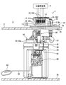
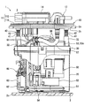
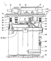
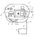
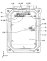
- FIG. 2 is a partial cross-sectional front view showing the fuel supply device of FIG. 1. It is a rear view which shows the fuel supply apparatus of FIG. It is a top view which shows the fuel supply apparatus of FIG.
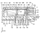
- FIG. 5 is a sectional view taken along line VV in FIG. 4. It is a perspective view which shows the inside of the circuit housing
- a fuel supply device 1 is mounted on a fuel tank 2 of a vehicle.
- the device 1 supplies fuel from the fuel tank 2 to the internal combustion engine outside the tank 2.
- the fuel tank 2 is formed in a hollow shape with resin, and stores fuel.
- the internal combustion engine to which fuel is supplied from the apparatus 1 may be a gasoline engine or a diesel engine.
- FIGS. 1 to 3 showing the mounting state of the device 1 on the fuel tank 2 the vertical direction and the horizontal direction substantially coincide with the vertical direction and horizontal direction of the vehicle on the horizontal plane, respectively.
- the apparatus 1 includes a tank lid unit 10, a sub tank 20, a holding cover 30, an adjustment mechanism 40, a pump unit 50, and a liquid level detection unit 60. Elements 20, 30, 40, 50, 60 other than the tank lid unit 10 in the device 1 are accommodated in the fuel tank 2.
- the tank lid unit 10 is mounted in a through hole 2b that penetrates the top plate 2a of the fuel tank 2. As shown in FIGS. 1 to 5, the tank lid unit 10 includes a resin lid body 11, a fuel pipe portion 12, a drive circuit 13, a heat radiation cover portion 14, a first metal terminal 15, a second metal terminal 16, and a third metal terminal 17. It has.
- the resin lid 11 has a flange portion 110 and a circuit housing portion 112 that are integrally formed of resin.
- a permeable resin that allows fuel vapor to pass therethrough for example, a polyacetal resin (that is, POM) that has excellent fuel resistance is used.
- POM polyacetal resin
- the flange portion 110 is formed in a circular plate shape with a permeable resin.
- the flange part 110 closes the through hole 2b by being fitted into the through hole 2b from the outside of the fuel tank 2.
- the circuit housing part 112 is formed in a bottomed rectangular tube shape with a permeable resin.
- the circuit housing part 112 partitions the internal space as the accommodation space 114.
- the circuit housing part 112 is located outside the fuel tank 2 by being disposed above the flange part 110.
- the circuit housing portion 112 has a plurality of ventilation spaces 116 between the circuit housing portion 112 and the flange portion 110. Each ventilation space 116 communicates with the fuel tank 2 and the external space 3 of the circuit housing portion 112.
- Ventilation spaces 116 suppress the permeation of the fuel vapor to the accommodation space 114 through the bottom portion 112a of the circuit housing portion 112 by allowing the fuel vapor that has passed through the flange portion 110 from the inside of the fuel tank 2 to escape to the external space 3. Yes.
- the fuel pipe portion 12 is formed into a tubular shape at the top and bottom of the flange portion 110 by being integrally formed with the resin lid body 11 by a permeable resin.
- the fuel pipe portion 12 protrudes from the flange portion 110 into the upper external space 3 so as to communicate with a fuel supply passage to the internal combustion engine. Further, the fuel pipe portion 12 is communicated with the fuel filter 53 of the pump unit 50 by projecting downward from the flange portion 110 in the fuel tank 2.
- the drive circuit 13 is an electronic circuit accommodated in the accommodation space 114 in the resin lid 11 as shown in FIG. 5 in order to drive the fuel pump 52 of the pump unit 50.
- the drive circuit 13 includes a circuit board 130 and a circuit element 132.
- the circuit board 130 is a printed wiring board such as a glass epoxy board, and is formed in a flat plate shape.
- the circuit board 130 is held by the side portion 112 b of the circuit housing portion 112, so that the accommodation space 114 is partitioned vertically and separated from the bottom portion 112 a of the housing portion 112.
- the circuit board 130 in the holding state is biased to the upper part of the accommodation space 114.
- Each circuit element 132 is mounted on both sides or one side of the circuit board 130.
- Each circuit element 132 is, for example, a chip capacitor or a resistance element in addition to the drive control IC 132a.
- the drive control IC 132a drives the fuel pump 52 in accordance with a control signal from the external circuit system 4 such as an ECU shown in FIG.
- the drive control IC 132 a that generates heat at this time is a “heat generating element” that generates the largest amount of heat among all the circuit elements 132.
- the heat radiating cover portion 14 is formed in a rectangular lid shape from, for example, a metal such as aluminium having excellent heat radiating properties.
- the heat dissipation cover portion 14 is fitted into the upper end opening of the circuit housing portion 112, thereby closing the upper end opening and covering the upper portion of the accommodation space 114.
- the circuit housing portion 112 protects the built-in drive circuit 13 by partitioning the housing space 114 in a liquid-tight and air-tight manner with respect to the external space 3 in cooperation with the heat dissipation cover portion 14 in the closed form.
- the accommodation space 114 is filled with a heat radiating gel (not shown) such as an epoxy gel.
- the heat radiating cover portion 14 can exhibit a heat radiating function by contacting with the drive control IC 132a that generates the largest amount of heat via a heat radiating gel.
- a plurality of first metal terminals 15 are provided at intervals.
- Each first metal terminal 15 is formed in an elongated bent plate shape, for example, with a metal such as tin-plated brass having excellent fuel resistance.
- Each first metal terminal 15 connects between the fuel pump 52 and the drive circuit 13 through the flange portion 110 and the bottom portion 112a of the circuit housing portion 112 of the resin lid body 11.
- Each first metal terminal 15 has a first exposed portion 150, a first embedded portion 152, and a first protruding portion 154.
- the first exposed portion 150 is electrically connected to the circuit board 130 by being exposed to the accommodation space 114.
- the first embedded portion 152 is embedded across the flange portion 110 and the bottom portion 112 a of the circuit housing portion 112.
- the first embedded portion 152 of the present embodiment is also embedded in the partition wall 118 that partitions the ventilation space 116 in the flange portion 110.
- the first protruding portion 154 is electrically connected to the fuel pump 52 by protruding downward in the fuel tank 2.
- Each second metal terminal 16 is formed in the shape of an elongated bent plate made of a metal such as tin-plated brass, similar to the first metal terminal 15.
- Each second metal terminal 16 connects between the external circuit system 4 and the drive circuit 13 by passing through the bottom 112a and the side 112b of the circuit housing 112 in the resin lid 11.
- Each second metal terminal 16 has a second exposed portion 160, a second embedded portion 162, and a second protruding portion 164.
- the second exposed portion 160 is electrically connected to the circuit board 130 by being exposed to the accommodation space 114.
- the second embedded portion 162 is embedded from the bottom portion 112a of the circuit housing portion 112 to the side portion 112b.
- the second protrusion 164 protrudes in the lateral direction exposed in the external space 3, thereby serving for electrical connection with the external circuit system 4. From the configuration of each second metal terminal 16 and the configuration of each first metal terminal 15 described above, the fuel pump 52 is driven by the drive circuit 13 according to the control of the external circuit system 4.
- Each third metal terminal 17 is formed in the shape of an elongated bent plate made of a metal such as tin-plated brass, similar to the first metal terminal 15.
- Each third metal terminal 17 passes between the external circuit system 4 and the liquid level detection unit 60 by passing through the flange portion 110 of the resin lid body 11 and the bottom portion 112a and the side portion 112b of the circuit housing portion 112. Connecting.
- Each third metal terminal 17 has a third embedded portion 172 and third projecting portions 174, 176.
- the third embedded portion 172 is embedded from the flange portion 110 to the bottom portion 112a and the side portion 112b of the circuit housing portion 112.
- the third embedded portion 172 of the present embodiment is also embedded in the partition wall 118.
- the upper third protrusion 174 protrudes in the lateral direction exposed in the external space 3, and is used for electrical connection with the external circuit system 4.
- the lower third protrusion 176 protrudes downward in the fuel tank 2 and is electrically connected to the liquid level detection unit 60.
- the external circuit system 4 receives the detection signal output from the liquid level detection unit 60 from the configuration of each third metal terminal 17 as described above, and detects the fuel level in the fuel tank 2.
- the sub tank 20 is formed in a bottomed cylindrical shape with resin.
- the sub tank 20 is disposed on the bottom plate portion 2 c of the fuel tank 2.
- the sub tank 20 stores the fuel transferred from the fuel tank 2.
- the holding cover 30 is formed of a resin in a circular lid shape.
- the holding cover 30 is fitted in the upper end opening of the sub tank 20 to close the upper end opening.
- the holding cover 30 has a receiving portion 32 that extends in a cylindrical shape upward, one on each side of the holding hole 31.
- the holding cover 30 further has a holding hole 31 penetrating in the vertical direction.
- the adjusting mechanism 40 has a pair of support columns 41 and elastic members 42 respectively.
- Each support column 41 is formed of a metal in a cylindrical shape, and is arranged extending in the vertical direction. The upper end portion of each column 41 is attached to the lower portion of the flange portion 110.
- Each column 41 is inserted into the corresponding accommodating portion 32 below the upper end portion. With this insertion form, each support column 41 is slidable in the vertical direction with respect to the holding cover 30.
- Each elastic member 42 is made of a metal coil spring, and is interposed between the corresponding accommodating portion 32 and the flange portion 110.
- Each elastic member 42 is elastically deformed according to the relative position between the accommodating portion 32 and the flange portion 110 to generate a restoring force. Due to the generation of the restoring force, each elastic member 42 presses the sub tank 20 integrally coupled to the holding cover 30 toward the lower bottom plate portion 2 c side of the fuel tank 2.
- the pump unit 50 is accommodated in the sub-tank 20 except for its upper part.
- the pump unit 50 includes a suction filter 51, a fuel pump 52, a fuel filter 53, and a relief valve 54.
- the suction filter 51 is provided at the lowermost part of the pump unit 50.
- the suction filter 51 is connected to the suction port of the fuel pump 52.
- the suction filter 51 filters the fuel drawn into the fuel pump 52 from the sub tank 20 to remove large foreign matters in the fuel.
- the fuel pump 52 is provided above the suction filter 51 in the pump unit 50.
- the fuel pump 52 is electrically connected to each first metal terminal 15 via a flexible wiring 56 that can be bent. By this electrical connection, the fuel pump 52 operates under the drive control from the drive circuit 13 to pressurize and discharge the intake fuel from the suction filter 51. At this time, the fuel pump 52 variably adjusts the pressure of the discharged fuel according to the drive control from the drive circuit 13.
- the fuel filter 53 is provided around the fuel pump 52 in the pump unit 50.
- the fuel filter 53 houses a filter element (not shown) such as a honeycomb filter medium in a filter case 53a.
- the filter case 53a is held by the inner peripheral portion of the holding hole 31 in a state of passing through the holding cover 30 in the vertical direction.
- the filter case 53a communicates with the discharge port of the fuel pump 52. Further, as shown in FIGS. 1 to 3, the filter case 53a communicates with the fuel pipe portion 12 via a flexible tube 57 that can be bent. With these communication modes, the fuel filter 53 filters the fuel that is discharged from the fuel pump 52 into the filter case 53a and then travels to the fuel pipe portion 12, thereby removing fine foreign matters in the fuel.
- the relief valve 54 is provided on the side of the fuel filter 53 in the pump unit 50.
- the relief valve 54 communicates with the fuel passage toward the fuel pipe portion 12 in the filter case 53a.
- the relief valve 54 releases the pressure when the pressure of the fuel supplied to the fuel pipe portion 12 through the fuel filter 53 exceeds a set pressure.
- the liquid level detection unit 60 is mounted on the outer peripheral portion of the sub tank 20.
- the liquid level detection unit 60 is a sender gauge in this embodiment.
- the liquid level detection unit 60 is electrically connected to each third metal terminal 17 through a flexible wiring 61 that can be bent.
- the arm 63 rotates as the float 62 floating in the fuel in the fuel tank 2 moves up and down. At this time, the rotation position of the arm 63 is a position corresponding to the fuel level in the fuel tank 2. Therefore, the liquid level detection unit 60 outputs a detection signal indicating the rotational position of the arm 63 to the external circuit system 4.
- the horizontal direction of FIG. 5 and the vertical direction of FIG. also, the horizontal direction in FIGS. 7 and 8 perpendicular to the X direction in the horizontal direction is defined as the Y direction. Furthermore, the vertical direction in FIGS. 5 and 8 perpendicular to the X and Y directions is defined as the Z direction.
- each first metal terminal 15 has a first exposed portion 150 in a flat plate shape having a constant thickness along a virtual reference plane S ⁇ b> 1 assumed to be perpendicular to the X direction in the lateral direction.
- the first embedded portion 152 is embedded in the center portion 112c in the X direction perpendicular to the reference plane S1 in the bottom portion 112a of the circuit housing portion 112 as shown in FIG.
- Each first metal terminal 15 is connected from the fuel pump 52 to the upper drive circuit 13 via the central portion 112c of such an embedded form.
- the first connection point P1 where the first exposed portion 150 of each first metal terminal 15 is connected to the circuit board 130 of the drive circuit 13 is at a position around the drive control IC 132a in the central portion 130a of the board 130. Is set.
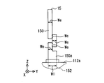
- the first exposed portion 150 is bent as shown in FIGS. 6 and 8 at a plurality of locations on the corresponding reference plane S1, and extends in a meandering shape.
- the first exposed portion 150 of this embodiment is meandering from the fuel pump 52 side to the upper drive circuit 13 side by being bent in the Y direction or the Z direction at a plurality of locations. With such a meandering shape, in each first metal terminal 15, the first exposed portion 150 can be elastically deformed at each bending point on the reference plane S1.
- each first metal terminal 15 at least the upper end portion of the first embedded portion 152 extends on the corresponding reference plane S1 as shown in FIG. 7 with a predetermined embedded width W1 as shown in FIG.
- the first exposed portion 150 has a meandering shape with an exposed width We smaller than the buried width Wl as shown in FIG. In other words, it has a crank shape).
- a portion near the boundary 150a with the first embedded portion 152 is formed to have substantially the same width as the embedded width Wl.
- each second metal terminal 16 has a second exposed portion 160 formed in a flat plate shape having a constant thickness along a virtual reference plane S ⁇ b> 2 that is assumed to be perpendicular to the X direction in the lateral direction.
- the second embedded portion 162 is embedded in the edge portion 112d in the X direction perpendicular to the reference plane S1 in the bottom portion 112a of the circuit housing portion 112 as shown in FIG.
- each second metal terminal 16 is brought closer to the side part 112b of the circuit housing part 112 than the first embedding part 152 in the X direction perpendicular to the reference plane S1 in the lateral direction, and the external circuit The connection from the system 4 to the drive circuit 13 is possible.
- the second connection point P2 where the second exposed portion 160 of each second metal terminal 16 is connected to the circuit board 130 of the drive circuit 13 is the first connection of each first metal terminal 15 at the edge 130b of the substrate 130. It is set at a position farther from the drive control IC 132a than the point P1.
- the second exposed portion 160 extends straight in the vertical direction as shown in FIG. 6 on the corresponding reference plane S2 as shown in FIG. With such a stretched configuration, the rigidity of the second exposed portion 160 in the Y and Z directions is set to be higher than the rigidity of the first exposed portion 150 that is elastically deformable in a meandering shape.
- the contact area where the first embedded portion 152 of each first metal terminal 15 comes into contact with the resin lid body 11 is different from that of the second embedded portion 162 of each second metal terminal 16. It is set to be larger than each of the contact areas in contact with. This is based on the fact that the contact area with the resin lid 11 is increased by embedding the first embedded portion 152 in the partition wall 118 that partitions the ventilation space 116 in the present embodiment.
- the first connection point P ⁇ b> 1 connected to the drive circuit 13 is the drive circuit 13.
- the position is set around the drive control IC 132a as a “heating element”.
- the first exposed portion 150 exposed to the accommodation space 114 in the resin lid 11 in the first metal terminal 15 where the position of the first connection point P1 is set is formed to be bent so as to be elastically deformable.
- the stress which acts on the 1st connection location P1 because the 1st exposed part 150 tracks and elastically deforms following thermal expansion and contraction. The amount of variation of the can be reduced.
- the second connection point P2 connected to the drive circuit 13 is the first connection point.
- the position is set farther from the drive control IC 132a than P1.
- the second exposed portion 160 exposed to the accommodation space 114 in the resin lid 11 in the second metal terminal 16 where the position of the second connection point P2 is set is formed with higher rigidity than the first exposed portion 150.
- the second exposed portion 160 of the device 1 has a higher rigidity than the first exposed portion 150 due to a simple shape that extends straight. According to this, in the second metal terminal 16 that is difficult to receive heat from the separated drive control IC 132a, even if the second exposed portion 160 is highly rigid, it acts on the second connection location P2 according to thermal expansion and contraction. The stress itself is reduced.
- the first metal terminal 15 that is easily subjected to heat from the surrounding drive control IC 132a has a larger contact area with the resin lid 11 than the second metal terminal 16, so that the resin lid due to thermal expansion and contraction. 11 is easily increased.
- the amount of fluctuation of the stress acting on the first connection location P1 can be reliably reduced by the elastic deformation of the first exposed portion 150 of the first metal terminal 15.
- the contact area with the resin lid 11 is smaller than that of the first metal terminal 15, so that the resin lid due to thermal expansion and contraction is obtained.
- the difference in thermal deformation amount from 11 can be kept small. Therefore, even if it is the 2nd metal terminal 16 which has the highly rigid 2nd exposed part 160, the stress itself which acts on the 2nd connection location P2 according to a thermal expansion / contraction can be reduced reliably.
- the first exposed portion 150 that is bent and extended at a plurality of locations of the first metal terminal 15 has a thermal expansion and contraction due to a meandering shape from the fuel pump 52 side toward the upper drive circuit 13 side. It is easy to follow its own elastic deformation. Thereby, even if thermal expansion / contraction occurs, the fluctuation amount of the stress acting on the first connection location P ⁇ b> 1 can be reduced by the reliable elastic deformation of the first exposed portion 150. Therefore, the effect of suppressing the stress fluctuation at the first connection point P1 can be enhanced, and the reliability of durability can be improved.
- the flat plate-like first exposed portion 150 along the reference plane S1 perpendicular to the lateral direction extends in a meandering shape on the reference plane S1. By doing so, it becomes easy to elastically deform up and down.
- the first exposed portion 150 follows the thermal expansion and contraction and reliably elastically deforms up and down, thereby acting on the first connection point P ⁇ b> 1. It is possible to reduce the amount of variation in stress. Therefore, the effect of suppressing the stress fluctuation at the first connection point P1 can be enhanced, and the reliability of durability can be improved.
- the first exposed portion 150 extends in a meandering shape with an exposed width We smaller than the embedded width Wl of the first embedded portion 152 embedded in the resin lid body 11. To do. According to this, in the flat plate-like first exposed portion 150 that is easily subjected to heat from the surrounding drive control IC 132a, the heat transfer amount to the first embedded portion 152 can be reduced. Therefore, it is possible to suppress an increase in the amount of thermal deformation caused by thermal expansion and contraction between the resin lid 11 and the first embedded portion 152, and to reduce the amount of fluctuation of the stress acting on the first connection location P1. it can. Therefore, such an apparatus 1 is particularly effective in enhancing the effect of suppressing the stress fluctuation at the first connection point P1 and improving the reliability of durability.
- the bottom portion 112 a of the bottomed circuit housing portion 112 that defines the housing space 114 in the resin lid body 11 is perpendicular to the reference plane S ⁇ b> 1 (that is, in the X direction in the present embodiment).
- the first metal terminal 15 is embedded in the central portion 112c. According to this, in the first metal terminal 15 connected to the central portion 130a that is easily deformed in the circuit board 130 that partitions the accommodation space 114 in the drive circuit 13, the deformation is absorbed by the elastic deformation of the first exposed portion 150. Can do. As a result, the stress acting on the first connection location P1 due to the deformation of the circuit board 130 can be reduced, which is particularly effective in improving the reliability of durability.
- the first exposed portion 150 of the first metal terminal 15 may be formed in a meandering shape curved at a plurality of locations as shown in FIG.
- the first exposed portion 150 of the first metal terminal 15 may be formed in a meandering shape that is bent in an oblique direction with respect to the Y and Z directions at a plurality of locations, as shown in FIG.
- the first metal terminal 150 may be formed in a curved shape in which the entire first exposed portion 150 is curved, for example, other than the meandering shape.
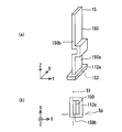
- the first metal terminal 15 may be formed in a meandering shape along 150b.
- the reference plane S1 extends in the X direction.
- the reference plane S ⁇ b> 1 may extend in a lateral direction other than the X direction and the Y direction as long as it is a plane parallel to the longitudinal direction of the first exposed portion 150.
- the exposed width We of the first exposed portion 150 in the flat first metal terminal 15 is substantially equal to or larger than the embedded width Wl of the first embedded portion 152 as shown in FIGS. It may be set.
- the exposed width We of the first exposed portion 150 in the flat first metal terminal 15 is stepwise within a range smaller than the embedded width Wl of the first embedded portion 152 as shown in FIG. It may be changed.
- the exposure width We2 in the vicinity of the first connection location P1 with the drive circuit 13 in the first exposure portion 150 is made smaller than the exposure width We1 in the other locations, so The degree of decrease in the amount of heat transfer to the portion 152 is increased.
- the first metal terminal 15 may be formed in a shape other than a flat plate, for example, in a linear shape, and the first exposed portion 150 may be formed in a meandering shape.
- the first embedded portion 152 of the first metal terminal 15 is embedded in a portion of the bottom portion 112a of the circuit housing portion 112 that is largely separated from the central portion 112c in the lateral direction perpendicular to the reference plane S1. May be.
- the first exposed portion 150 may not include the boundary vicinity portion 150a having substantially the same width as the first embedded portion 152 in the first metal terminal 15.
- the contact area where the first embedded portion 152 contacts the resin lid body 11 in the first metal terminal 15 is changed to the contact area where the second exposed portion 160 contacts the resin lid body 11 in the second metal terminal 16.
- it may be set small or substantially equal.
- the second exposed portion 160 of the second metal terminal 16 may be formed in a shape other than a straight as long as the rigidity is higher than that of the first exposed portion 150 of the first metal terminal 15.
- the X direction and the Y direction may be interchanged.
- the ventilation space 116 and the partition wall 118 may not be provided.
- the third metal terminal 17 and the liquid level detection unit 60 may not be provided.
Landscapes
- Engineering & Computer Science (AREA)
- Chemical & Material Sciences (AREA)
- Combustion & Propulsion (AREA)
- Mechanical Engineering (AREA)
- General Engineering & Computer Science (AREA)
- Life Sciences & Earth Sciences (AREA)
- Sustainable Development (AREA)
- Sustainable Energy (AREA)
- Transportation (AREA)
- Cooling, Air Intake And Gas Exhaust, And Fuel Tank Arrangements In Propulsion Units (AREA)
Abstract
樹脂により形成される樹脂蓋体(11)は、内部の収容空間(114)に駆動回路(13)を収容する。樹脂蓋体(11)を経由して燃料ポンプ及び駆動回路(13)の間を接続するために金属により形成され、駆動回路(13)と接続された第一接続箇所(P1)が「発熱体」としての駆動制御(IC132a)の周囲に位置設定される第一金属ターミナル(15)では、収容空間(114)に露出する第一露出部(150)が弾性変形可能に曲がって形成される。樹脂蓋体(11)を経由して外部回路系及び駆動回路(13)の間を接続するために金属により形成され、駆動回路(13)と接続された第二接続箇所(P2)が第一接続箇所(P1)よりも駆動制御(IC132a)から離間して位置設定される第二金属ターミナル(16)では、収容空間(114)に露出する第二露出部(160)が第一露出部(150)よりも高剛性に形成される。
Description
本願は、2015年12月14日に出願された日本国特許出願第2015-243348号に基づくものであり、この開示をもってその内容を本明細書中に開示したものとする。
本開示は、タンク蓋ユニット及び燃料供給装置に関する。
従来、燃料ポンプにより燃料タンク内から燃料タンク外へと向かって燃料を供給する燃料供給装置では、タンク蓋ユニットが燃料タンクの貫通孔に装着されている。こうしたタンク蓋ユニットの一種として特許文献1には、外部回路系の制御に従って燃料タンク内の燃料ポンプを駆動するために駆動回路を内蔵したものが、開示されている。
具体的に、特許文献1のタンク蓋ユニットにおいて燃料タンクの貫通孔を閉塞する樹脂蓋体は、内部の収容空間に駆動回路を収容している。この樹脂蓋体を経由して燃料ポンプ及び駆動回路の間を接続するための金属ターミナルは、金属により形成されて、L字状に延伸している。また、樹脂蓋体を経由して外部回路系及び駆動回路の間を接続するための金属ターミナルも、金属により形成されて、L字状に延伸している。
しかし、特許文献1のタンク蓋ユニットにおいて金属ターミナルのいずれについても、樹脂蓋体に一部が埋設されていると共に、収容空間を埋める樹脂部により別の一部が覆われている。その結果、樹脂部を含む樹脂蓋体と金属ターミナルとの間には、熱膨縮による熱変形量の差が発生することで、金属ターミナルと駆動回路との接続箇所に作用する応力が当該熱膨縮に応じて変動する。ここで特に、金属ターミナルの接続箇所が駆動回路のうち発熱体の周囲に位置設定されている場合には、周囲の発熱体から熱を受け易い金属ターミナルの接続箇所にて、応力の変動量が増大する。このような応力変動は、金属ターミナルと駆動回路との接続不良を招いてしまうため、耐久性の観点からして望ましくない。
本開示は、以上説明した問題に鑑みてなされたものであって、その目的は、耐久性が確保されるタンク蓋ユニット及び燃料供給装置を、提供することにある。
上述の課題を解決するために、本開示の一つの態様では、
燃料タンクの貫通孔に装着され、外部回路系の制御に従って燃料タンク内の燃料ポンプを駆動するために、発熱体を有する駆動回路を内蔵したタンク蓋ユニットにおいて、
樹脂により形成され、貫通孔を閉塞する樹脂蓋体であって、内部の収容空間に駆動回路を収容した樹脂蓋体と、
樹脂蓋体を経由して燃料ポンプ及び駆動回路の間を接続するために金属により形成され、駆動回路と接続された第一接続箇所が発熱体の周囲に位置設定される第一金属ターミナルであって、収容空間に露出する第一露出部が弾性変形可能に曲がって形成された第一金属ターミナルと、
樹脂蓋体を経由して外部回路系及び駆動回路の間を接続するために金属により形成され、駆動回路と接続された第二接続箇所が第一接続箇所よりも発熱体から離間して位置設定される第二金属ターミナルであって、収容空間に露出する第二露出部が第一露出部よりも高剛性に形成された第二金属ターミナルとを、備えるタンク蓋ユニットを提供する。
燃料タンクの貫通孔に装着され、外部回路系の制御に従って燃料タンク内の燃料ポンプを駆動するために、発熱体を有する駆動回路を内蔵したタンク蓋ユニットにおいて、
樹脂により形成され、貫通孔を閉塞する樹脂蓋体であって、内部の収容空間に駆動回路を収容した樹脂蓋体と、
樹脂蓋体を経由して燃料ポンプ及び駆動回路の間を接続するために金属により形成され、駆動回路と接続された第一接続箇所が発熱体の周囲に位置設定される第一金属ターミナルであって、収容空間に露出する第一露出部が弾性変形可能に曲がって形成された第一金属ターミナルと、
樹脂蓋体を経由して外部回路系及び駆動回路の間を接続するために金属により形成され、駆動回路と接続された第二接続箇所が第一接続箇所よりも発熱体から離間して位置設定される第二金属ターミナルであって、収容空間に露出する第二露出部が第一露出部よりも高剛性に形成された第二金属ターミナルとを、備えるタンク蓋ユニットを提供する。
また、上述の課題を解決するために、本開示の別の態様では、
燃料タンク内から燃料タンク外へ向かって燃料を供給する燃料ポンプと、
燃料タンクの貫通孔に装着され、外部回路系の制御に従って燃料タンク内の燃料ポンプを駆動するために、発熱体を有する駆動回路を内蔵したタンク蓋ユニットと、
を、含んで構成される燃料供給装置において、
タンク蓋ユニットは、
樹脂により形成され、貫通孔を閉塞する樹脂蓋体であって、内部の収容空間に駆動回路を収容した樹脂蓋体と、
樹脂蓋体を経由して燃料ポンプ及び駆動回路の間を接続するために金属により形成され、駆動回路と接続された第一接続箇所が発熱体の周囲に位置設定される第一金属ターミナルであって、収容空間に露出する第一露出部が弾性変形可能に曲がって形成された第一金属ターミナルと、
樹脂蓋体を経由して外部回路系及び駆動回路の間を接続するために金属により形成され、駆動回路と接続された第二接続箇所が第一接続箇所よりも発熱体から離間して位置設定される第二金属ターミナルであって、収容空間に露出する第二露出部が第一露出部よりも高剛性に形成された第二金属ターミナルとを、備える燃料供給装置を提供する。
燃料タンク内から燃料タンク外へ向かって燃料を供給する燃料ポンプと、
燃料タンクの貫通孔に装着され、外部回路系の制御に従って燃料タンク内の燃料ポンプを駆動するために、発熱体を有する駆動回路を内蔵したタンク蓋ユニットと、
を、含んで構成される燃料供給装置において、
タンク蓋ユニットは、
樹脂により形成され、貫通孔を閉塞する樹脂蓋体であって、内部の収容空間に駆動回路を収容した樹脂蓋体と、
樹脂蓋体を経由して燃料ポンプ及び駆動回路の間を接続するために金属により形成され、駆動回路と接続された第一接続箇所が発熱体の周囲に位置設定される第一金属ターミナルであって、収容空間に露出する第一露出部が弾性変形可能に曲がって形成された第一金属ターミナルと、
樹脂蓋体を経由して外部回路系及び駆動回路の間を接続するために金属により形成され、駆動回路と接続された第二接続箇所が第一接続箇所よりも発熱体から離間して位置設定される第二金属ターミナルであって、収容空間に露出する第二露出部が第一露出部よりも高剛性に形成された第二金属ターミナルとを、備える燃料供給装置を提供する。
これらの各態様によると、樹脂蓋体を経由して燃料ポンプ及び駆動回路の間を接続するための第一金属ターミナルでは、駆動回路と接続された第一接続箇所が駆動回路のうち発熱体の周囲に位置設定される。こうして第一接続箇所の位置設定された第一金属ターミナルにおいて樹脂蓋体内の収容空間に露出する第一露出部は、弾性変形可能に曲がって形成される。これによれば、周囲の発熱体から熱を受け易い第一金属ターミナルでは、第一露出部が熱膨縮に追従して弾性変形することで、第一接続箇所に作用する応力の変動量が低減され得る。
また一方、樹脂蓋体を経由して外部回路系及び駆動回路の間を接続するための第二金属ターミナルでは、駆動回路と接続された第二接続箇所が第一接続箇所よりも発熱体から離間して位置設定される。こうして第二接続箇所の位置設定された第二金属ターミナルにおいて収容空間に露出する第二露出部は、第一露出部よりも高剛性に形成される。これによれば、離間した発熱体からは熱を受け難い第二金属ターミナルでは、第二露出部が高剛性であっても、熱膨縮に応じて第二接続箇所に作用する応力自体が小さくなる。
以上のことから第一及び第二接続箇所では、応力変動を抑制して接続不良を発生し難くすることができるので、耐久性を確保することが可能となる。
以下、本開示の一実施形態を図面に基づいて説明する。
図1~3に示すように、本開示の一実施形態による燃料供給装置1は、車両の燃料タンク2に搭載される。装置1は、燃料タンク2内から同タンク2外の内燃機関へと燃料を供給する。ここで燃料タンク2は、樹脂により中空状に形成されることで、燃料を貯留する。また、装置1からの燃料供給先の内燃機関は、ガソリンエンジンであってもよいし、ディーゼルエンジンであってもよい。尚、燃料タンク2への装置1の搭載状態を示す図1~3において上下方向と横方向とはそれぞれ、水平面上における車両の鉛直方向と水平方向とに実質一致している。
(全体構成)
まず、装置1の全体構成を説明する。装置1は、タンク蓋ユニット10、サブタンク20、保持カバー30、調整機構40、ポンプユニット50及び液面検出ユニット60を含んで構成されている。装置1のうちタンク蓋ユニット10以外の要素20,30,40,50,60は、燃料タンク2内に収容される。
まず、装置1の全体構成を説明する。装置1は、タンク蓋ユニット10、サブタンク20、保持カバー30、調整機構40、ポンプユニット50及び液面検出ユニット60を含んで構成されている。装置1のうちタンク蓋ユニット10以外の要素20,30,40,50,60は、燃料タンク2内に収容される。
タンク蓋ユニット10は、燃料タンク2のうち天板部2aを貫通する貫通孔2bに、装着されている。図1~5に示すようにタンク蓋ユニット10は、樹脂蓋体11、燃料管部12、駆動回路13、放熱カバー部14、第一金属ターミナル15、第二金属ターミナル16及び第三金属ターミナル17を備えている。
樹脂蓋体11は、樹脂により一体成形されたフランジ部110及び回路筐体部112を、有している。樹脂蓋体11の形成樹脂としては、燃料蒸気を透過させる透過性樹脂、例えば耐燃料性に優れたポリアセタール樹脂(即ち、POM)等が、採用される。この透過性樹脂の採用により、燃料タンク2内において燃料が気化してなる燃料蒸気は、樹脂蓋体11を透過可能となっている。
フランジ部110は、透過性樹脂により円形板状に形成されている。フランジ部110は、燃料タンク2の外側から貫通孔2bに嵌合させられることで、当該貫通孔2bを閉塞する。回路筐体部112は、透過性樹脂により有底の矩形筒状に形成されている。回路筐体部112は、内部空間を収容空間114として区画している。回路筐体部112は、フランジ部110の上方に配置されることで、燃料タンク2外に位置している。回路筐体部112は、図5に示すように、フランジ部110との間に複数の通気空間116をあけている。各通気空間116は、燃料タンク2及び回路筐体部112の外部空間3と連通している。これら通気空間116は、燃料タンク2内からフランジ部110を透過した燃料蒸気を外部空間3へ逃がすことで、回路筐体部112の底部112aを通じた収容空間114への燃料蒸気の透過を抑えている。
図1~4に示すように燃料管部12は、透過性樹脂により樹脂蓋体11と一体成形されることで、フランジ部110の上下において管状に形成されている。燃料管部12は、フランジ部110から上方の外部空間3に突出することで、内燃機関への燃料の供給通路と連通する。さらに燃料管部12は、燃料タンク2内にてフランジ部110から下方へ突出することで、ポンプユニット50の燃料フィルタ53と連通している。
駆動回路13は、ポンプユニット50の燃料ポンプ52を駆動するために、図5の如く樹脂蓋体11内の収容空間114に収容された電子回路である。駆動回路13は、回路基板130及び回路素子132を有している。回路基板130は、例えばガラスエポキシ基板等のプリント配線基板であり、平板状に形成されている。回路基板130は、回路筐体部112の側部112bにより保持されることで、収容空間114を上下に仕切って同筐体部112の底部112aから離間している。この保持状態にある回路基板130は、収容空間114のうち上部に偏って位置している。各回路素子132は、回路基板130の両面又は片面に実装されている。各回路素子132は、駆動制御IC132aの他、例えばチップコンデンサや抵抗素子等である。ここで駆動制御IC132aは、図1に示す例えばECU等の外部回路系4からの制御信号に従って、燃料ポンプ52を駆動する。このときに発熱する駆動制御IC132aは、全回路素子132の中で最も発熱量の大きい「発熱体」となっている。
図1~5に示すように放熱カバー部14は、例えば放熱性に優れたアルムニウム等の金属により、矩形蓋状に形成されている。放熱カバー部14は、回路筐体部112の上端開口部に嵌合させられることで、当該上端開口部を閉塞して収容空間114の上部を覆っている。この閉塞形態の放熱カバー部14との共同により回路筐体部112は、外部空間3に対して収容空間114を液密且つ気密に仕切ることで、内蔵した駆動回路13を保護している。ここで収容空間114には、例えばエポキシゲル等の図示しない放熱ゲルが充填されている。図5に示すように放熱カバー部14は、発熱量が最大の駆動制御IC132aとは放熱ゲルを介して接触することで、放熱機能を発揮可能となっている。
第一金属ターミナル15は、互いに間隔をあけて複数設けられている。各第一金属ターミナル15は、例えば耐燃料性に優れたすずめっき黄銅等の金属により、細長の屈曲板状に形成されている。各第一金属ターミナル15は、樹脂蓋体11のうちフランジ部110と回路筐体部112の底部112aとを経由することで、燃料ポンプ52及び駆動回路13の間を接続している。
各第一金属ターミナル15は、第一露出部150、第一埋設部152及び第一突出部154を有している。具体的に第一露出部150は、収容空間114に露出することで、回路基板130と電気接続されている。第一埋設部152は、フランジ部110から回路筐体部112の底部112aに跨って、埋設されている。特に本実施形態の第一埋設部152は、フランジ部110において通気空間116を仕切る仕切壁118にも、埋設されている。第一突出部154は、燃料タンク2内となる下方へ突出することで、燃料ポンプ52と電気接続されている。
図1,5に示すように第二金属ターミナル16は、互いに間隔をあけて複数設けられている。各第二金属ターミナル16は、第一金属ターミナル15と同様な、例えばすずめっき黄銅等の金属により、細長の屈曲板状に形成されている。各第二金属ターミナル16は、樹脂蓋体11のうち回路筐体部112の底部112a及び側部112bを経由することで、外部回路系4及び駆動回路13の間を接続する。
各第二金属ターミナル16は、第二露出部160、第二埋設部162及び第二突出部164を有している。具体的に第二露出部160は、収容空間114に露出することで、回路基板130と電気接続されている。第二埋設部162は、回路筐体部112の底部112aから側部112bに跨って、埋設されている。第二突出部164は、外部空間3に露出する横方向へと突出することで、外部回路系4との電気接続に供される。このような各第二金属ターミナル16の構成と、上述した各第一金属ターミナル15の構成とから、外部回路系4の制御に従う駆動回路13により燃料ポンプ52が駆動される。
第三金属ターミナル17は、互いに間隔をあけて複数設けられている。各第三金属ターミナル17は、第一金属ターミナル15と同様な、例えばすずめっき黄銅等の金属により、細長の屈曲板状に形成されている。各第三金属ターミナル17は、樹脂蓋体11のうちフランジ部110と回路筐体部112の底部112a及び側部112bとを経由することで、外部回路系4及び液面検出ユニット60の間を接続する。
各第三金属ターミナル17は、第三埋設部172及び第三突出部174,176を有している。具体的に第三埋設部172は、フランジ部110から回路筐体部112の底部112a及び側部112bに跨って、埋設されている。特に本実施形態の第三埋設部172は、仕切壁118にも埋設されている。上側の第三突出部174は、外部空間3に露出する横方向へと突出することで、外部回路系4との電気接続に供される。下側の第三突出部176は、燃料タンク2内となる下方へ突出することで、液面検出ユニット60と電気接続されている。このような各第三金属ターミナル17の構成から外部回路系4は、液面検出ユニット60から出力される検出信号を受信することで、燃料タンク2内における燃料の液面高さを検出する。
図1~3に示すようにサブタンク20は、樹脂により有底の円筒状に形成されている。サブタンク20は、燃料タンク2の底板部2c上に配置される。サブタンク20は、燃料タンク2内から移送される燃料を、貯留する。
図1~4に示すように保持カバー30は、樹脂により円形蓋状に形成されている。保持カバー30は、サブタンク20の上端開口部に嵌合させられることで、当該上端開口部を閉塞している。保持カバー30は、上方へ向かって円筒状に延出する収容部32を、保持孔31の両側に一つずつ有している。保持カバー30はさらに、図1~3に示すように、上下方向に貫通する保持孔31を、有している。
調整機構40は、支柱41及び弾性部材42を、それぞれ一対ずつ有している。各支柱41は、金属により円筒状に形成され、上下方向に延伸して配置されている。各支柱41の上端部は、フランジ部110の下部に装着されている。各支柱41は、上端部よりも下方において、それぞれ対応する収容部32に挿入されている。この挿入形態により各支柱41は、保持カバー30に対して上下方向にスライド可能となっている。各弾性部材42は、金属製のコイルスプリングからなり、それぞれ対応する収容部32とフランジ部110との間に介装されている。各弾性部材42は、収容部32とフランジ部110との相対位置に応じて弾性変形することで、復原力を発生する。この復原力の発生により各弾性部材42は、保持カバー30に対して一体に結合されたサブタンク20を、燃料タンク2のうち下方の底板部2c側へ向かって押圧する。
図1~4に示すようにポンプユニット50は、その上部を除いて、サブタンク20内に収容されている。ポンプユニット50は、サクションフィルタ51、燃料ポンプ52、燃料フィルタ53及びリリーフバルブ54を有している。
図2に示すようにサクションフィルタ51は、ポンプユニット50の最下部に設けられている。サクションフィルタ51は、燃料ポンプ52の吸入口に連結されている。サクションフィルタ51は、サブタンク20内から燃料ポンプ52へ吸入される燃料を濾過して、当該燃料中の大きな異物を除去する。燃料ポンプ52は、ポンプユニット50においてサクションフィルタ51の上側に設けられている。燃料ポンプ52は、湾曲自在なフレキシブル配線56を介して、各第一金属ターミナル15と電気接続されている。この電気接続により燃料ポンプ52は、駆動回路13からの駆動制御を受けて作動することで、サクションフィルタ51からの吸入燃料を加圧して吐出する。このとき燃料ポンプ52は、吐出する燃料の圧力を、駆動回路13からの駆動制御に従って可変調整する。
図1~4に示すように燃料フィルタ53は、ポンプユニット50において燃料ポンプ52の周囲に設けられている。燃料フィルタ53は、例えばハニカム状濾材等の図示しないフィルタエレメントを、フィルタケース53a内に収容している。フィルタケース53aは、保持カバー30を上下方向に貫通した状態で、保持孔31の内周部により保持されている。フィルタケース53aは、燃料ポンプ52の吐出口と連通している。さらにフィルタケース53aは、図1~3に示すように、湾曲自在なフレキシブルチューブ57を介して、燃料管部12と連通している。これらの連通形態により燃料フィルタ53は、燃料ポンプ52からフィルタケース53a内へ吐出されてから燃料管部12へと向かう燃料を濾過して、当該燃料中の微細な異物を除去する。
図2に示すようにリリーフバルブ54は、ポンプユニット50において燃料フィルタ53の側方に設けられている。リリーフバルブ54は、フィルタケース53aにおいて燃料管部12へと向かう燃料通路と連通している。リリーフバルブ54は、燃料フィルタ53を通して燃料管部12へと供給された燃料の圧力が設定圧以上になると、当該圧力を逃がす。
図1~4に示すように液面検出ユニット60は、サブタンク20の外周部に装着されている。液面検出ユニット60は、本実施形態ではセンダゲージである。液面検出ユニット60は、湾曲自在なフレキシブル配線61を介して、各第三金属ターミナル17と電気接続されている。液面検出ユニット60では、燃料タンク2内の燃料に浮遊するフロート62が上下動することで、アーム63が回転する。このときアーム63の回転位置は、燃料タンク2内における燃料の液面高さに対応した位置となる。そこで液面検出ユニット60は、アーム63の回転位置を表す検出信号を外部回路系4へと出力する。
(詳細構成)
次に、装置1の詳細構成を説明する。尚、以下では、横方向のうち図5の左右方向且つ図7の上下方向を、X方向と定義する。また、横方向のうちX方向に対して垂直な図7,8の左右方向を、Y方向と定義する。さらに、X,Y方向に対して垂直な図5,8の上下方向を、Z方向と定義する。
次に、装置1の詳細構成を説明する。尚、以下では、横方向のうち図5の左右方向且つ図7の上下方向を、X方向と定義する。また、横方向のうちX方向に対して垂直な図7,8の左右方向を、Y方向と定義する。さらに、X,Y方向に対して垂直な図5,8の上下方向を、Z方向と定義する。
図7に示すように各第一金属ターミナル15は、横方向のうちX方向に対して垂直に想定される仮想的な基準平面S1に沿って一定厚の平板状に、第一露出部150を有している。各第一金属ターミナル15において第一埋設部152は、回路筐体部112の底部112aのうち、基準平面S1に垂直なX方向の中央部112cに、図5の如く埋設されている。各第一金属ターミナル15は、こうした埋設形態の中央部112cを経由して、燃料ポンプ52から上方の駆動回路13までの間を接続している。
各第一金属ターミナル15の第一露出部150が駆動回路13の回路基板130と接続された第一接続箇所P1は、同基板130の中央部130aにて、駆動制御IC132aの周囲となる位置に設定されている。各第一金属ターミナル15において第一露出部150は、それぞれ対応する基準平面S1上の複数箇所にて図6,8の如く曲げられて、蛇行形状に延伸している。特に本実施形態の第一露出部150は、複数箇所にてY方向又はZ方向に屈曲されることで、燃料ポンプ52側から上方の駆動回路13側へと向かって蛇行している。こうした蛇行形状により各第一金属ターミナル15では、基準平面S1上の各曲げ箇所にて第一露出部150が弾性変形可能となっている。
各第一金属ターミナル15において第一埋設部152の少なくとも上端部は、それぞれ図7の如く対応した基準平面S1上にて、図8の如く所定の埋設幅Wlをもって延伸している。一方、各第一金属ターミナル15において第一露出部150は、第一埋設部152との境界近傍部分150aを除いて、図8の如き埋設幅Wlよりも小さな露出幅Weをもって蛇行形状(即ち、言い換えればクランク状)に延伸している。尚、第一露出部150において第一埋設部152との境界近傍部分150aは、埋設幅Wlと実質同一幅に形成されている。
図7に示すように各第二金属ターミナル16は、横方向のうちX方向に対して垂直に想定される仮想的な基準平面S2に沿って一定厚の平板状に、第二露出部160を有している。各第二金属ターミナル16において第二埋設部162は、回路筐体部112の底部112aのうち、基準平面S1に垂直なX方向の縁部112dに、図5の如く埋設されている。こうした埋設形態により各第二金属ターミナル16は、横方向のうち基準平面S1に垂直なX方向にて、第一埋設部152よりも回路筐体部112の側部112bに近づけられて、外部回路系4から駆動回路13までの間を接続可能となっている。
各第二金属ターミナル16の第二露出部160が駆動回路13の回路基板130と接続された第二接続箇所P2は、同基板130の縁部130bにて各第一金属ターミナル15の第一接続箇所P1よりも駆動制御IC132aから離間した位置に、設定されている。各第二金属ターミナル16において第二露出部160は、それぞれ図7の如く対応した基準平面S2上にて、図6の如く上下方向にストレートに延伸している。こうした延伸形態により、Y,Z方向での第二露出部160の剛性は、蛇行形状で弾性変形可能な第一露出部150の剛性よりも、高く設定されている。
図5に示すように、各第一金属ターミナル15の第一埋設部152が樹脂蓋体11と接触する接触面積のそれぞれは、各第二金属ターミナル16の第二埋設部162が樹脂蓋体11と接触する接触面積のそれぞれよりも、大きく設定されている。これは本実施形態では、第一埋設部152が通気空間116を仕切る仕切壁118に埋設されていることで、樹脂蓋体11との接触面積を増大させていることに、依拠している。
(作用効果)
以上説明した装置1の作用効果を、以下に説明する。
以上説明した装置1の作用効果を、以下に説明する。
装置1によると、樹脂蓋体11を経由して燃料ポンプ52及び駆動回路13の間を接続するための第一金属ターミナル15では、駆動回路13と接続された第一接続箇所P1が駆動回路13のうち「発熱体」としての駆動制御IC132aの周囲に位置設定される。こうして第一接続箇所P1の位置設定された第一金属ターミナル15において樹脂蓋体11内の収容空間114に露出する第一露出部150は、弾性変形可能に曲がって形成される。これによれば、周囲の駆動制御IC132aから熱を受け易い第一金属ターミナル15では、第一露出部150が熱膨縮に追従して弾性変形することで、第一接続箇所P1に作用する応力の変動量が低減され得る。
また一方、樹脂蓋体11を経由して外部回路系4及び駆動回路13の間を接続するための第二金属ターミナル16では、駆動回路13と接続された第二接続箇所P2が第一接続箇所P1よりも駆動制御IC132aから離間して位置設定される。こうして第二接続箇所P2の位置設定された第二金属ターミナル16において樹脂蓋体11内の収容空間114に露出する第二露出部160は、第一露出部150よりも高剛性に形成される。ここで特に装置1の第二露出部160は、ストレートに延伸する簡素な形状により、第一露出部150よりも高い剛性を確保されている。これによれば、離間した駆動制御IC132aからは熱を受け難い第二金属ターミナル16では、第二露出部160が高剛性であっても、熱膨縮に応じて第二接続箇所P2に作用する応力自体が小さくなる。
以上のことから第一及び第二接続箇所P1,P2では、応力変動を抑制して接続不良を発生し難くすることができるので、耐久性を確保することが可能となる。
さらに装置1によると、周囲の駆動制御IC132aから熱を受け易い第一金属ターミナル15では、樹脂蓋体11との接触面積が第二金属ターミナル16よりも大きいことで、熱膨縮による樹脂蓋体11との熱変形量差が増大し易くなっている。しかし、そうした熱膨縮が生じても、第一接続箇所P1に作用する応力の変動量は、第一金属ターミナル15の有する第一露出部150の弾性変形により確実に低減され得る。
また一方で、離間した駆動制御IC132aからは熱を受け難い第二金属ターミナル16では、樹脂蓋体11との接触面積が第一金属ターミナル15よりも小さくなることで、熱膨縮による樹脂蓋体11との熱変形量差が小さく抑えられ得る。故に、高剛性の第二露出部160を有した第二金属ターミナル16であっても、熱膨縮に応じて第二接続箇所P2に作用する応力自体を、確実に低減することができる。
以上によれば、第一及び第二接続箇所P1,P2における応力変動の抑制効果を高めて、耐久性の信頼度を向上させることが可能となる。
またさらに装置1によると、第一金属ターミナル15の複数箇所にて屈曲されて延伸する第一露出部150は、燃料ポンプ52側から上方の駆動回路13側へと向かう蛇行形状により、熱膨縮に対して自身の弾性変形を追従させ易い。これにより熱膨縮が生じても、第一接続箇所P1に作用する応力の変動量は、第一露出部150の確実な弾性変形によって低減され得る。故に、第一接続箇所P1における応力変動の抑制効果を高めて、耐久性の信頼度を向上させることが可能となる。
加えて装置1によると、横方向(即ち、本実施形態ではX方向)に対して垂直な基準平面S1に沿う平板状の第一露出部150は、当該基準平面S1上にて蛇行形状に延伸することで、上下に弾性変形し易くなっている。これによれば、燃料ポンプ52から上方の駆動回路13までの間にて、第一露出部150が熱膨縮に追従して上下に確実に弾性変形することで、第一接続箇所P1に作用する応力の変動量を低減することができる。故に、第一接続箇所P1における応力変動の抑制効果を高めて、耐久性の信頼度を向上させることが可能となる。
また加えて装置1によると、第一金属ターミナル15では、樹脂蓋体11に埋設された第一埋設部152の埋設幅Wlよりも小さな露出幅Weをもって、第一露出部150が蛇行形状に延伸する。これによれば、周囲の駆動制御IC132aから熱を受け易い平板状の第一露出部150では、第一埋設部152までの伝熱量が低下し得る。故に、樹脂蓋体11と第一埋設部152との間にて熱膨縮による熱変形量差が大きくなるのを抑えて、第一接続箇所P1に作用する応力の変動量を低減することができる。したがって、このような装置1は、第一接続箇所P1における応力変動の抑制効果を高めて、耐久性の信頼度を向上させる上で特に有効となる。
さらに加えて装置1によると、樹脂蓋体11において収容空間114を区画した有底の回路筐体部112の底部112aでは、基準平面S1に垂直な横方向(即ち、本実施形態ではX方向)の中央部112cに、第一金属ターミナル15が埋設される。これによれば、駆動回路13のうち収容空間114を仕切る回路基板130において変形し易い中央部130aに接続の第一金属ターミナル15では、第一露出部150の弾性変形により当該変形を吸収することができる。その結果、回路基板130の変形に起因して第一接続箇所P1に作用する応力は低減され得るので、耐久性の信頼度を向上させる上で特に有効となる。
(他の実施形態)
以上、本開示の一実施形態について説明したが、本開示は、当該実施形態に限定して解釈されるものではなく、本開示の要旨を逸脱しない範囲内において種々の実施形態に適用することができる。
以上、本開示の一実施形態について説明したが、本開示は、当該実施形態に限定して解釈されるものではなく、本開示の要旨を逸脱しない範囲内において種々の実施形態に適用することができる。
具体的に変形例1では、第一金属ターミナル15の第一露出部150を、図9に示すように、複数箇所にて湾曲させた蛇行形状に形成してもよい。変形例2では、第一金属ターミナル15の第一露出部150を、図10に示すように、複数箇所にてY,Z方向に対する斜め方向に屈曲させた蛇行形状に形成してもよい。変形例3では、蛇行形状以外、例えば第一露出部150の全体が湾曲する湾曲形状等に、第一金属ターミナル150を形成してもよい。
変形例4では、図11(a)、(b)に示すように基準平面S1とは垂直に想定される仮想的な垂直平面Spに対して、第一露出部150の端面(X方向における端面)150bが沿う蛇行形状に、第一金属ターミナル15を形成してもよい。なお、図11(a)、(b)に示す変形例4では、基準平面S1はX方向に延びている。また、基準平面S1は、第一露出部150の長手方向に平行な平面であれば、X方向およびY方向以外の横方向に延びていても良い。変形例5では、平板状の第一金属ターミナル15において第一露出部150の露出幅Weを、図12,13に示すように、第一埋設部152の埋設幅Wlに対して実質等しく又は大きく設定してもよい。
変形例6では、平板状の第一金属ターミナル15において第一露出部150の露出幅Weを、図14に示すように第一埋設部152の埋設幅Wlよりも小さい範囲にて、段階的に変化させてもよい。ここで図14の変形例6では、第一露出部150において駆動回路13との第一接続箇所P1近傍の露出幅We2を、その他の箇所の露出幅We1よりも小さくすることで、第一埋設部152への伝熱量の低下度合いを高めている。
変形例7では、第一金属ターミナル15を平板状以外、例えば線状等に形成して、そのうちの第一露出部150を蛇行形状に形成してもよい。変形例8では、回路筐体部112の底部112aのうち、基準平面S1に垂直な横方向にて中央部112cから大きく外れた箇所に、第一金属ターミナル15の第一埋設部152を埋設させてもよい。
変形例9では、第一金属ターミナル15において第一埋設部152と実質同一幅の境界近傍部分150aを、第一露出部150に設けなくてもよい。変形例10では、第一金属ターミナル15において第一埋設部152が樹脂蓋体11と接触する接触面積を、第二金属ターミナル16において第二露出部160が樹脂蓋体11と接触する接触面積に対して、小さく又は実質等しく設定してもよい。
変形例11では、第一金属ターミナル15の第一露出部150よりも高剛性となる限りにて、第二金属ターミナル16の第二露出部160をストレート以外の形状に、形成してもよい。変形例12では、X方向とY方向とを入れ替えてもよい。変形例13では、通気空間116及び仕切壁118を設けなくてもよい。変形例14では、第三金属ターミナル17及び液面検出ユニット60を設けなくてもよい。
Claims (8)
- 燃料タンク(2)の貫通孔(2b)に装着され、外部回路系(4)の制御に従って前記燃料タンク(2)内の燃料ポンプ(52)を駆動するために、発熱体(132a)を有する駆動回路(13)を内蔵したタンク蓋ユニットにおいて、
樹脂により形成され、前記貫通孔(2b)を閉塞する樹脂蓋体(11)であって、内部の収容空間(114)に前記駆動回路(13)を収容した樹脂蓋体(11)と、
前記樹脂蓋体(11)を経由して前記燃料ポンプ(52)及び前記駆動回路(13)の間を接続するために金属により形成され、前記駆動回路(13)と接続された第一接続箇所(P1)が前記発熱体(132a)の周囲に位置設定される第一金属ターミナル(15)であって、前記収容空間(114)に露出する第一露出部(150)が弾性変形可能に曲がって形成された第一金属ターミナル(15)と、
前記樹脂蓋体(11)を経由して前記外部回路系(4)及び前記駆動回路(13)の間を接続するために金属により形成され、前記駆動回路(13)と接続された第二接続箇所(P2)が前記第一接続箇所(P1)よりも前記発熱体(132a)から離間して位置設定される第二金属ターミナル(16)であって、前記収容空間(114)に露出する第二露出部(160)が前記第一露出部(150)よりも高剛性に形成された第二金属ターミナル(16)とを、備えるタンク蓋ユニット。 - 前記第一金属ターミナル(15)が前記樹脂蓋体(11)と接触する接触面積は、前記第二金属ターミナル(16)が前記樹脂蓋体(11)と接触する接触面積よりも、大きい請求項1に記載のタンク蓋ユニット。
- 前記第一露出部(150)は、複数箇所にて曲げられることにより前記燃料ポンプ(52)側から上方の前記駆動回路(13)側へ向かって蛇行した蛇行形状に、延伸する請求項1又は2に記載のタンク蓋ユニット。
- 前記第一金属ターミナル(15)は、横方向に対して垂直な基準平面(S1)に沿った平板状の前記第一露出部(150)を、有し、
前記第一露出部(150)は、前記基準平面(S1)上にて前記蛇行形状に延伸する請求項3に記載のタンク蓋ユニット。 - 前記第一金属ターミナル(15)は、前記樹脂蓋体(11)に埋設された埋設部(152)を、前記第一露出部(150)と共に有し、
前記基準平面(S1)上にて前記埋設部(152)は、所定の埋設幅(Wl)をもって延伸し、
前記基準平面(S1)上にて前記第一露出部(150)は、前記埋設幅(Wl)よりも小さな露出幅(We)をもって前記蛇行形状に延伸する請求項4に記載のタンク蓋ユニット。 - 前記樹脂蓋体(11)は、前記収容空間(114)を区画する有底の回路筐体部(112)を、有し、
前記駆動回路(13)は、前記収容空間(114)を上下に仕切って配置される回路基板(130)を、有し、
前記第一金属ターミナル(15)は、前記回路筐体部(112)の底部(112a)のうち、前記基準平面(S1)に垂直な前記横方向の中央部(112c)に埋設される請求項1~5のいずれか一項に記載のタンク蓋ユニット。 - 前記第二露出部(160)は、ストレートに延伸する請求項1~6のいずれか一項に記載のタンク蓋ユニット。
- 燃料タンク(2)内から前記燃料タンク(2)外へ向かって燃料を供給する燃料ポンプ(52)と、
前記燃料タンク(2)の貫通孔(2b)に装着され、外部回路系(4)の制御に従って前記燃料タンク(2)内の燃料ポンプ(52)を駆動するために、発熱体(132a)を有する駆動回路(13)を内蔵したタンク蓋ユニット(10)と、
を、含んで構成される燃料供給装置において、
前記タンク蓋ユニット(10)は、
樹脂により形成され、前記貫通孔(2b)を閉塞する樹脂蓋体(11)であって、内部の収容空間(114)に前記駆動回路(13)を収容した樹脂蓋体(11)と、
前記樹脂蓋体(11)を経由して前記燃料ポンプ(52)及び前記駆動回路(13)の間を接続するために金属により形成され、前記駆動回路(13)と接続された第一接続箇所(P1)が前記発熱体(132a)の周囲に位置設定される第一金属ターミナル(15)であって、前記収容空間(114)に露出する第一露出部(150)が弾性変形可能に曲がって形成された第一金属ターミナル(15)と、
前記樹脂蓋体(11)を経由して前記外部回路系(4)及び前記駆動回路(13)の間を接続するために金属により形成され、前記駆動回路(13)と接続された第二接続箇所(P2)が前記第一接続箇所(P1)よりも前記発熱体(132a)から離間して位置設定される第二金属ターミナル(16)であって、前記収容空間(114)に露出する第二露出部(160)が前記第一露出部(150)よりも高剛性に形成された第二金属ターミナル(16)とを、備える燃料供給装置。
Priority Applications (3)
| Application Number | Priority Date | Filing Date | Title |
|---|---|---|---|
| US15/776,165 US10780775B2 (en) | 2015-12-14 | 2016-11-21 | Tank lid unit and fuel supply device |
| CN201680072718.9A CN108368802B (zh) | 2015-12-14 | 2016-11-21 | 箱盖单元及燃料供给装置 |
| KR1020187014351A KR102078798B1 (ko) | 2015-12-14 | 2016-11-21 | 탱크 덮개 유닛 및 연료 공급 장치 |
Applications Claiming Priority (2)
| Application Number | Priority Date | Filing Date | Title |
|---|---|---|---|
| JP2015-243348 | 2015-12-14 | ||
| JP2015243348A JP6459947B2 (ja) | 2015-12-14 | 2015-12-14 | タンク蓋ユニット及び燃料供給装置 |
Publications (1)
| Publication Number | Publication Date |
|---|---|
| WO2017104353A1 true WO2017104353A1 (ja) | 2017-06-22 |
Family
ID=59056382
Family Applications (1)
| Application Number | Title | Priority Date | Filing Date |
|---|---|---|---|
| PCT/JP2016/084441 Ceased WO2017104353A1 (ja) | 2015-12-14 | 2016-11-21 | タンク蓋ユニット及び燃料供給装置 |
Country Status (5)
| Country | Link |
|---|---|
| US (1) | US10780775B2 (ja) |
| JP (1) | JP6459947B2 (ja) |
| KR (1) | KR102078798B1 (ja) |
| CN (1) | CN108368802B (ja) |
| WO (1) | WO2017104353A1 (ja) |
Families Citing this family (4)
| Publication number | Priority date | Publication date | Assignee | Title |
|---|---|---|---|---|
| KR101821588B1 (ko) * | 2016-04-22 | 2018-01-25 | 주식회사 코아비스 | 방열 성능을 개선한 연료펌프 모듈 및 이를 제조하는 연료펌프 모듈 제조방법 |
| JP6723954B2 (ja) * | 2017-04-28 | 2020-07-15 | 愛三工業株式会社 | 燃料ポンプ |
| JP6742469B1 (ja) * | 2019-04-16 | 2020-08-19 | 三菱電機株式会社 | 燃料供給装置 |
| JP6808079B1 (ja) * | 2020-01-31 | 2021-01-06 | 三菱電機株式会社 | 燃料供給装置、および船外機 |
Citations (6)
| Publication number | Priority date | Publication date | Assignee | Title |
|---|---|---|---|---|
| JP2004169565A (ja) * | 2002-11-18 | 2004-06-17 | Mikuni Corp | インタンクポンプ用電子ユニット |
| JP2007165003A (ja) * | 2005-12-09 | 2007-06-28 | Ngk Spark Plug Co Ltd | コネクタ及びコネクタ付き回路基板ケース |
| JP2010053753A (ja) * | 2008-08-27 | 2010-03-11 | Aisan Ind Co Ltd | 燃料供給装置 |
| JP2011163212A (ja) * | 2010-02-09 | 2011-08-25 | Denso Corp | 燃料供給装置 |
| JP2011202646A (ja) * | 2010-03-26 | 2011-10-13 | Denso Corp | 燃料供給装置 |
| US20140318646A1 (en) * | 2013-04-30 | 2014-10-30 | Kia Motors Corporation | Controller integrated fuel pump module |
Family Cites Families (12)
| Publication number | Priority date | Publication date | Assignee | Title |
|---|---|---|---|---|
| JP3794879B2 (ja) | 1999-09-30 | 2006-07-12 | 株式会社日立製作所 | 燃料供給装置 |
| US6837744B2 (en) * | 2002-03-13 | 2005-01-04 | Hydro-Aire, Inc. | Electrical connector for aircraft fuel pumps |
| JP2004124817A (ja) * | 2002-10-02 | 2004-04-22 | Mitsubishi Electric Corp | 燃料ポンプモジュールおよび車両用の燃料タンク内圧センサ |
| JP2006002658A (ja) * | 2004-06-17 | 2006-01-05 | Hitachi Ltd | 燃料供給装置 |
| JP2006329079A (ja) * | 2005-05-26 | 2006-12-07 | Toyota Motor Corp | 燃料供給モジュール |
| JP2008291701A (ja) | 2007-05-23 | 2008-12-04 | Denso Corp | 燃料供給装置 |
| JP2009071071A (ja) * | 2007-09-13 | 2009-04-02 | Denso Corp | 電子回路部品実装構造及びその製造方法 |
| DE102009046446A1 (de) * | 2009-11-06 | 2011-05-12 | Robert Bosch Gmbh | Elektronisches Bauelement |
| KR20110067240A (ko) * | 2009-12-14 | 2011-06-22 | 주식회사 코아비스 | 드라이버 일체형 bldc 연료펌프 모듈 |
| US8869775B2 (en) * | 2010-02-09 | 2014-10-28 | Denso Corporation | Fuel supply apparatus |
| JP2012256558A (ja) * | 2011-06-10 | 2012-12-27 | Meitaku Kogyo Kk | 大判面光源装置 |
| CN104813018B (zh) * | 2013-10-21 | 2018-01-09 | 玄谭产业株式会社 | 安装有控制装置的车用燃料泵模块 |
-
2015
- 2015-12-14 JP JP2015243348A patent/JP6459947B2/ja not_active Expired - Fee Related
-
2016
- 2016-11-21 CN CN201680072718.9A patent/CN108368802B/zh not_active Expired - Fee Related
- 2016-11-21 KR KR1020187014351A patent/KR102078798B1/ko not_active Expired - Fee Related
- 2016-11-21 WO PCT/JP2016/084441 patent/WO2017104353A1/ja not_active Ceased
- 2016-11-21 US US15/776,165 patent/US10780775B2/en not_active Expired - Fee Related
Patent Citations (6)
| Publication number | Priority date | Publication date | Assignee | Title |
|---|---|---|---|---|
| JP2004169565A (ja) * | 2002-11-18 | 2004-06-17 | Mikuni Corp | インタンクポンプ用電子ユニット |
| JP2007165003A (ja) * | 2005-12-09 | 2007-06-28 | Ngk Spark Plug Co Ltd | コネクタ及びコネクタ付き回路基板ケース |
| JP2010053753A (ja) * | 2008-08-27 | 2010-03-11 | Aisan Ind Co Ltd | 燃料供給装置 |
| JP2011163212A (ja) * | 2010-02-09 | 2011-08-25 | Denso Corp | 燃料供給装置 |
| JP2011202646A (ja) * | 2010-03-26 | 2011-10-13 | Denso Corp | 燃料供給装置 |
| US20140318646A1 (en) * | 2013-04-30 | 2014-10-30 | Kia Motors Corporation | Controller integrated fuel pump module |
Also Published As
| Publication number | Publication date |
|---|---|
| US10780775B2 (en) | 2020-09-22 |
| KR20180063898A (ko) | 2018-06-12 |
| JP2017110503A (ja) | 2017-06-22 |
| CN108368802A (zh) | 2018-08-03 |
| KR102078798B1 (ko) | 2020-02-19 |
| CN108368802B (zh) | 2020-06-16 |
| US20190009671A1 (en) | 2019-01-10 |
| JP6459947B2 (ja) | 2019-01-30 |
Similar Documents
| Publication | Publication Date | Title |
|---|---|---|
| JP6459947B2 (ja) | タンク蓋ユニット及び燃料供給装置 | |
| US10072621B2 (en) | Tank lid unit and fuel supply device | |
| JP4724159B2 (ja) | 電子制御ユニット及び車両挙動制御装置 | |
| KR101893602B1 (ko) | 탱크 덮개 유닛 및 연료 공급 장치 | |
| US9689340B2 (en) | Controller integrated fuel pump module | |
| CN113853837B (zh) | 电子控制装置 | |
| KR20140129756A (ko) | 컨트롤러 일체형 연료펌프 모듈 | |
| JP2007056820A (ja) | 燃料供給装置 | |
| JP2013015073A (ja) | ポンプ制御ユニット | |
| JP5082997B2 (ja) | キャパシタモジュール | |
| JP4686304B2 (ja) | 電子装置および電子装置の製造方法 | |
| JP4862850B2 (ja) | 燃料供給装置 | |
| JP6590986B1 (ja) | 燃料供給装置 | |
| KR101164778B1 (ko) | 연료탱크 내부 장착형 드라이버 구비 연료펌프 모듈 | |
| JP5708180B2 (ja) | ポンプ制御モジュール | |
| JP5316458B2 (ja) | 燃料供給装置 | |
| JP5691771B2 (ja) | ポンプ制御モジュール | |
| JP2008196440A (ja) | 燃料供給装置 | |
| JP2009241702A (ja) | ブレーキ液圧制御装置 | |
| JP6465945B1 (ja) | 燃料供給装置 | |
| CN104685983B (zh) | 电路基板支承装置 | |
| WO2014050980A1 (ja) | 回路基板支持装置 | |
| JP2012141290A (ja) | 燃料タンク構造 |
Legal Events
| Date | Code | Title | Description |
|---|---|---|---|
| 121 | Ep: the epo has been informed by wipo that ep was designated in this application |
Ref document number: 16875337 Country of ref document: EP Kind code of ref document: A1 |
|
| ENP | Entry into the national phase |
Ref document number: 20187014351 Country of ref document: KR Kind code of ref document: A |
|
| NENP | Non-entry into the national phase |
Ref country code: DE |
|
| 122 | Ep: pct application non-entry in european phase |
Ref document number: 16875337 Country of ref document: EP Kind code of ref document: A1 |