WO2017098979A1 - 丸鋸刃の振れを抑えることができる丸鋸盤 - Google Patents
丸鋸刃の振れを抑えることができる丸鋸盤 Download PDFInfo
- Publication number
- WO2017098979A1 WO2017098979A1 PCT/JP2016/085549 JP2016085549W WO2017098979A1 WO 2017098979 A1 WO2017098979 A1 WO 2017098979A1 JP 2016085549 W JP2016085549 W JP 2016085549W WO 2017098979 A1 WO2017098979 A1 WO 2017098979A1
- Authority
- WO
- WIPO (PCT)
- Prior art keywords
- saw blade
- movable
- circular saw
- cutting
- machining head
- Prior art date
Links
Images


Classifications
-
- B—PERFORMING OPERATIONS; TRANSPORTING
- B23—MACHINE TOOLS; METAL-WORKING NOT OTHERWISE PROVIDED FOR
- B23D—PLANING; SLOTTING; SHEARING; BROACHING; SAWING; FILING; SCRAPING; LIKE OPERATIONS FOR WORKING METAL BY REMOVING MATERIAL, NOT OTHERWISE PROVIDED FOR
- B23D45/00—Sawing machines or sawing devices with circular saw blades or with friction saw discs
- B23D45/02—Sawing machines or sawing devices with circular saw blades or with friction saw discs with a circular saw blade or the stock mounted on a carriage
-
- B—PERFORMING OPERATIONS; TRANSPORTING
- B23—MACHINE TOOLS; METAL-WORKING NOT OTHERWISE PROVIDED FOR
- B23D—PLANING; SLOTTING; SHEARING; BROACHING; SAWING; FILING; SCRAPING; LIKE OPERATIONS FOR WORKING METAL BY REMOVING MATERIAL, NOT OTHERWISE PROVIDED FOR
- B23D47/00—Sawing machines or sawing devices working with circular saw blades, characterised only by constructional features of particular parts
- B23D47/005—Vibration-damping
-
- B—PERFORMING OPERATIONS; TRANSPORTING
- B23—MACHINE TOOLS; METAL-WORKING NOT OTHERWISE PROVIDED FOR
- B23D—PLANING; SLOTTING; SHEARING; BROACHING; SAWING; FILING; SCRAPING; LIKE OPERATIONS FOR WORKING METAL BY REMOVING MATERIAL, NOT OTHERWISE PROVIDED FOR
- B23D47/00—Sawing machines or sawing devices working with circular saw blades, characterised only by constructional features of particular parts
- B23D47/08—Sawing machines or sawing devices working with circular saw blades, characterised only by constructional features of particular parts of devices for bringing the circular saw blade to the workpiece or removing same therefrom
-
- B—PERFORMING OPERATIONS; TRANSPORTING
- B27—WORKING OR PRESERVING WOOD OR SIMILAR MATERIAL; NAILING OR STAPLING MACHINES IN GENERAL
- B27B—SAWS FOR WOOD OR SIMILAR MATERIAL; COMPONENTS OR ACCESSORIES THEREFOR
- B27B5/00—Sawing machines working with circular or cylindrical saw blades; Components or equipment therefor
- B27B5/29—Details; Component parts; Accessories
- B27B5/30—Details; Component parts; Accessories for mounting or securing saw blades or saw spindles
-
- B—PERFORMING OPERATIONS; TRANSPORTING
- B23—MACHINE TOOLS; METAL-WORKING NOT OTHERWISE PROVIDED FOR
- B23D—PLANING; SLOTTING; SHEARING; BROACHING; SAWING; FILING; SCRAPING; LIKE OPERATIONS FOR WORKING METAL BY REMOVING MATERIAL, NOT OTHERWISE PROVIDED FOR
- B23D45/00—Sawing machines or sawing devices with circular saw blades or with friction saw discs
- B23D45/02—Sawing machines or sawing devices with circular saw blades or with friction saw discs with a circular saw blade or the stock mounted on a carriage
- B23D45/021—Sawing machines or sawing devices with circular saw blades or with friction saw discs with a circular saw blade or the stock mounted on a carriage with the saw blade mounted on a carriage
-
- B—PERFORMING OPERATIONS; TRANSPORTING
- B23—MACHINE TOOLS; METAL-WORKING NOT OTHERWISE PROVIDED FOR
- B23D—PLANING; SLOTTING; SHEARING; BROACHING; SAWING; FILING; SCRAPING; LIKE OPERATIONS FOR WORKING METAL BY REMOVING MATERIAL, NOT OTHERWISE PROVIDED FOR
- B23D47/00—Sawing machines or sawing devices working with circular saw blades, characterised only by constructional features of particular parts
- B23D47/02—Sawing machines or sawing devices working with circular saw blades, characterised only by constructional features of particular parts of frames; of guiding arrangements for work-table or saw-carrier
- B23D47/025—Sawing machines or sawing devices working with circular saw blades, characterised only by constructional features of particular parts of frames; of guiding arrangements for work-table or saw-carrier of tables
Definitions
- the present invention relates to a circular saw machine for cutting a workpiece to be cut.
- a conventional circular saw machine includes a machining head having a rotatable circular saw blade, and this machining head is movable in a cutting direction for cutting a workpiece and in the opposite direction.
- a region located on the cutting direction side of the circular saw blade is a cutting region having a cutting action.
- the machining head is provided with a pair of fixed saw blade guide sets that guide it so as to sandwich the body of the circular saw blade on both sides of the cutting area of the circular saw blade at an appropriate position (appropriate position of the machining head).
- the pair of fixed saw blade guide sets are separated from each other in a direction orthogonal to the cutting direction.
- the interval between the pair of fixed saw blade guide sets in the orthogonal direction is the maximum workpiece width (maximum width) to be cut. The interval is set according to.
- the interval in the orthogonal direction of the pair of fixed saw blade guide sets is set as described above, and when performing a cutting process on a workpiece to be cut with a small width, The distance between the fixed saw blade guide set and the cut portion of the workpiece becomes large, and the rigidity of the cutting area in the circular saw blade cannot be ensured sufficiently. Therefore, the circular saw blade is likely to be bent during the cutting process, and the processing accuracy (surface accuracy) of the cut surface of the workpiece may be reduced.
- the conventional circular saw machine has a problem that it is difficult to increase the machining accuracy of the cut surface of the workpiece by suppressing the bending of the circular saw blade during the cutting process regardless of the width of the workpiece. .
- An object of the present invention is to provide a circular saw machine having a novel configuration capable of solving the above-described problems.
- a machining head having a circular saw blade that is movable in a cutting direction for giving a cut to a workpiece and in the opposite direction and having a rotatable circular saw blade, and the cutting direction and the opposite to the machining head.
- the body of the circular saw blade on the radially inner side (the radially inner side of the circular saw blade) of the cutting region provided so as to be movable in a direction (radial direction of the circular saw blade) and having a cutting action in the circular saw blade
- the movable saw blade guide set is guided so as to sandwich the workpiece, and when the cutting into the workpiece progresses, the movable saw blade guide set moves in the opposite direction in conjunction with the movement of the machining head in the cutting direction.
- a circular saw machine is provided that is configured to move relative to the machining head.
- the circular saw is provided in the machining head so as to be spaced apart in a direction perpendicular to the cutting direction, and the body of the circular saw blade on both sides of the cutting region (both sides in the orthogonal direction). It further comprises a pair of fixed saw blade guide sets for guiding so as to sandwich them.
- the circular saw machine includes a stopper for restricting movement of the movable saw blade guide set relative to the machining head in the cutting direction, and biasing the movable saw blade guide set in the cutting direction.
- a force member Preferably, the circular saw machine further includes an actuator for moving the movable saw blade guide set relative to the machining head in the cutting direction and the opposite direction.
- the movable saw blade guide set is divided in a direction perpendicular to the cutting direction.
- the processing head includes a saw blade case that accommodates the circular saw blade, and the saw blade case is provided in the case main body, the case main body, and the case main body.
- the movable saw blade guide set is provided on the inner side surface of the case body so as to be movable in the cutting direction and the opposite direction, and the body of the circular saw blade.
- the processing head is moved in the cutting direction while the circular saw blade is rotated. Then, the workpiece can be cut by the circular saw blade, and the workpiece can be cut.
- the movable saw blade guide set guides the circular saw blade so as to sandwich the body portion of the circular saw blade in the radial direction inside the cutting region.
- the movable saw blade guide set moves relative to the machining head in the opposite direction in conjunction with the movement of the machining head in the cutting direction. Thereby, the movable saw blade guide set does not hinder the workpiece cutting process.
- the swing of the circular saw blade when the circular saw blade enters the work can be suppressed regardless of the width of the work. Therefore, according to the present invention, regardless of the width of the workpiece, it is possible to suppress the bending of the circular saw blade during the cutting process and increase the machining accuracy of the cut surface of the workpiece.
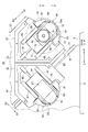
- FIG. 1 is a schematic front view of a circular saw machine according to an embodiment of the present invention.
- FIG. 2 is an enlarged view of a main part of the circular saw machine according to the embodiment of the present invention.
- FIG. 3 is a diagram showing a main part of the embodiment of the present invention, and shows a state in which the front side of the case body is opened by the case lid.
- FIG. 4 is an enlarged view taken along line IV-IV in FIG.
- FIGS. 5A and 5B are diagrams for explaining the operation of the movable saw blade guide set and the like according to the embodiment of the present invention.
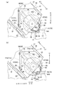
- FIG. 6 is a diagram showing a main part of a first modification of the embodiment of the present invention, and shows a state in which the front side of the case body is opened by the case lid.
- FIGS. 7A and 7B are views for explaining the operation of the movable saw blade guide set and the like according to the first modification of the embodiment of the present invention.
- FIG. 8 is a diagram showing a main part of a second modification of the embodiment of the present invention, and shows a state where the front side of the case body is opened by the case lid.
- FIGS. 9A and 9B are diagrams for explaining the operation of the movable saw blade guide set and the like according to the second modification of the embodiment of the present invention.
- Providing means to provide indirectly through another member in addition to providing directly, and is synonymous with “providing”.
- the “radial direction” refers to the radial direction of the circular saw blade, and the “radial inner side” refers to the radial inner side of the circular saw blade.
- “Cutting position” refers to a position in the transport direction where cutting is performed. In the drawings, “FF” is the forward direction (conveying direction), “FR” is the backward direction, “L” is the left direction, “R” is the right direction, “U” is the upward direction, and “D”. Indicates the downward direction.
- the circular saw machine 1 performs a cutting process on a portion to be cut of a bar-shaped workpiece W positioned at a cutting position in a conveyance direction (forward direction).
- the structure of the circular saw machine 1 which concerns on embodiment of this invention is as follows.
- the circular saw 1 is provided on a base (bed) 3 extending in the transport width direction (left-right direction) orthogonal to the transport direction and on the left part of the upper surface of the base 3.
- the support frame 5 is provided.
- the support frame 5 has an inclined surface 5f that is inclined with respect to the horizontal direction (left-right direction).
- the base 3 includes a main body vice 7 for fixing the workpiece W to the base 3 on the upstream side (right upstream in the transport direction) of the cutting position on the upper surface (the upper surface of the base 3).
- the main body vise 7 has a vise bed (processing table) 9 that is provided on the upper surface of the base 3 and supports the workpiece W.
- the vise bed 9 includes a fixed vise jaw 11 on the left side of the upper surface (the upper surface of the vise bed 9).
- the vice bed 9 includes a movable vise jaw 13 that clamps the workpiece W in cooperation with the fixed vise jaw 11 on the upper surface thereof, and the movable vise jaw 13 is movable in the conveyance width direction.
- the vice bed 9 includes a hydraulic vise cylinder 15 that moves the movable vise jaw 13 in the conveyance width direction on the right side of the upper surface thereof.
- the base 3 includes a transport table (not shown) that supports the workpiece W so as to be movable in the transport direction on the rear side (the rear side of the base 3). Further, the transport table includes a transport vise (not shown) that transports the workpiece W in the transport direction at an appropriate position (appropriate position of the transport table).
- the support frame 5 includes a plurality of (only one shown) guide rails 17 extending in the inclined direction on the inclined surface 5f.
- the plurality of guide rails 17 include a machining head 21 having a rotatable circular saw blade 19 between them (between the plurality of guide rails 17).
- the circular saw blade 19 has a disc-shaped body portion 19b and a plurality (a large number) of cutting teeth 19t provided on the outer peripheral surface of the body portion 19b.
- a region located on the cutting direction D1 side in the circular saw blade 19 is a cutting region 19A that exhibits a cutting action.
- the machining head 21 is guided by a corresponding guide rail 17 on the lower surface (lower surface of the machining head 21) in the cutting direction (one side in the inclined direction) D1 and the opposite direction (the other side in the inclined direction) D2.
- a guided member 23 is provided.
- the machining head 21 is provided on the inclined surface 5f of the support frame 5 so as to be movable in the cutting direction D1 and the opposite direction D2 via the plurality of guide rails 17 and the plurality of guided members 23.
- the support frame 5 is provided with a machining head electric motor 25 as a machining head actuator for moving the machining head 21 in the cutting direction D1 and the opposite direction D2 on the support frame 5.
- the output shaft (not shown) of the machining head electric motor 25 is linked to the machining head 21 via a ball screw (not shown) and a nut member (not shown).
- a hydraulic machining head cylinder (not shown) may be used as the machining head actuator.
- the machining head 21 includes a movable box 27 provided on the inclined surface 5 f of the support frame 5 so as to be movable in the cutting direction D ⁇ b> 1 and the opposite direction D ⁇ b> 2, and below the movable box 27.
- a saw blade case 29 for accommodating a part of the circular saw blade 19.
- the saw blade case 29 is provided at a lower portion of the movable box 27 with a case main body 31 and a plurality of hinges (hinges) 33 provided on the case main body 31, and the front side of the case main body 31 can be opened and closed.
- a case lid (case cover) 35 is provided.
- the case lid 35 has a shape that approximates the case main body 31.
- the case main body 31 has a first rib 37 on the upper side of the inner side surface (the inner side surface of the case main body 31), and most of the first rib 37 is L-shaped when viewed from the front. .
- the case main body 31 has an insertion hole 39 at the center (the center of the case main body 31).
- the case lid 35 has a second rib 41 at the upper part of the inner side surface (the inner side surface of the case lid 35), and the front view of most of the second rib 41 is L-shaped. ing.
- the second rib 41 is integrally joined to the first rib 37 by a plurality of bolts 43.
- the case lid 35 is integrally joined to the case main body 31 by the plurality of bolts 43 with the front side of the case main body 31 closed.
- the movable box 27 includes a main shaft 45 inside the movable box 27 via a bearing 47 or the like, and the main shaft 45 can rotate around its axis (axis of the main shaft 45). ing.
- the front end portion of the main shaft 45 is inserted through an insertion hole 39.
- the circular saw blade 19 is fixed to the front end portion of the main shaft 45 by a bolt 51 with a pair of mounting flanges (mounting plates) 49 interposed therebetween. ing.
- the movable box 27 is provided with an electric motor 53 for a saw blade for rotating the circular saw blade 19 at an upper portion thereof. Further, the output shaft (not shown) of the saw blade electric motor 53 is linked to the main shaft 45 via a gear mechanism (not shown) and a belt mechanism (not shown) provided in the movable box.
- the saw blade case 29 is a pair of fixed saw blades that guide the saw blade case 29 at appropriate positions (appropriate positions of the saw blade case 29) so as to sandwich the body portion 19b of the circular saw blade 19 on both sides of the cutting region 19A of the circular saw blade 19.
- a guide set 55 is provided.
- the pair of fixed saw blade guide sets 55 are separated in a direction perpendicular to the cutting direction D1.
- Each fixed saw blade guide set 55 is in contact with the first bracket 57 fixed to the inner surface of the case body 31 and the back surface of the body portion 19b of the circular saw blade 19 provided at the tip of the first bracket 57.
- First fixed insert 59 is made of a hard material such as carbide.
- each fixed saw blade guide set 55 is provided on the surface of the second bracket 61 fixed to the inner surface of the case lid 35 and the body 19b of the circular saw blade 19 provided at the tip of the second bracket 61. It has the 2nd fixed insert 63 which can contact.
- the second fixed insert 63 is made of, for example, a hard material such as cemented carbide.
- the case main body 31 includes a pair of first slide guides 65 extending in the cutting direction D1 on the inner side surface (inner side surface of the case main body 31), and each first slide guide 65 has an L-shaped cross section. It has become.
- the case lid 35 includes a pair of second slide guides 67 extending in the cutting direction D1 on its inner side surface (inner side surface of the case lid 35). It has a letter shape.
- the saw blade case 29 has a body portion 19b of the circular saw blade 19 between the pair of fixed saw blade guide sets 55 on the radially inner side of the cutting area 19A of the circular saw blade 19 (the radially inner side of the circular saw blade 19).
- a movable saw blade guide set 69 is provided for guiding so as to be sandwiched.
- the movable saw blade guide set 69 is movable in the cutting direction D1 and the opposite direction D2 via the pair of first slide guides 65 and the pair of second slide guides 67.
- the movable saw blade guide set 69 has a first movable plate 71 provided on the inner surface of the case body 31 so as to be movable in the cutting direction D1 and the opposite direction D2 via a pair of first slide guides 65.
- the first movable plate 71 is formed with a first notch 73 for inserting the mounting flange 49, and the first movable plate 71 is not in contact with the mounting flange 49.
- the movable saw blade guide set 69 has a first movable insert 75 that is provided at the tip of the first movable plate 71 and that can contact the back surface of the body 19 b of the circular saw blade 19.
- the first movable insert 75 is made of, for example, a hard material such as cemented carbide.
- the movable saw blade guide set 69 has a second movable plate 77 provided on the inner surface of the case lid 35 through a pair of second slide guides 67 so as to be movable in the cutting direction D1 and the opposite direction D2.
- the second movable plate 77 is formed with a second notch 79 for inserting the mounting flange 49, and the second movable plate 77 is not in contact with the mounting flange 49.
- the movable saw blade guide set 69 has a second movable insert 81 that is provided at the tip of the second movable plate 77 and can contact the surface of the body 19 b of the circular saw blade 19.
- the 2nd movable insert 81 consists of hard materials, such as super hard, for example.
- the case main body 31 includes a first stopper 83 that restricts the movement of the first movable plate 71 in the cutting direction D1 at an appropriate position on the inner side surface (the inner side surface of the case main body 31).
- the case body 31 includes a first spring 85 as a first urging member for urging the first movable plate 71 in the cutting direction D1 (on the first stopper 83 side) at the upper part of the inner side surface.
- the case lid 35 includes a second stopper 87 that regulates the movement of the second movable plate 77 in the cutting direction D1 at an appropriate position on the inner side surface (the inner side surface of the case lid 35).
- the case lid 35 includes a second spring 89 as a second urging member that urges the second movable plate 77 in the cutting direction D1 (second stopper 87 side) at the upper part of the inner side surface thereof.
- the saw blade case 29 includes stoppers 83 and 87 that restrict the movement of the movable saw blade guide set 69 in the cutting direction D1 at an appropriate position on the inner side surface (the inner screen of the saw blade case 29).
- the saw blade case 29 includes springs 85 and 89 as biasing members that bias the movable saw blade guide set 69 in the cutting direction D1 at the upper part of the inner side surface thereof.
- the movable saw blade guide set 69 is moved in the cutting direction D1 to a part of the fixed saw blade guide set 55 (the first bracket 57 and the second bracket 61). You may add the function to regulate.
- the movable saw blade guide set 69 is attached with the springs 85 and 89 while maintaining a predetermined contact state when the circular saw blade 19 is cut into the workpiece W. It is configured to move relative to the machining head 21 in the opposite direction D2 while resisting the force.
- the predetermined contact state is a state in which the first movable insert 75 and the second movable insert 81 are in contact with the workpiece W, as well as a contact member provided in the movable saw blade guide set 69 ( (Not shown) includes a state in which the workpiece W or a fixed portion such as the fixed vise jaw 11 is in contact with the fixed portion.
- the second movable plate 77 may be integrally connected to the first movable plate 71 by a connection pin (not shown) or the like. In this case, any one of the first spring 85 and the second spring 89 may be omitted.
- the workpiece W After carrying the workpiece W into the conveyance table, the workpiece W is conveyed in the conveyance direction by the conveyance vise, and the cut portion of the workpiece W is positioned at the cutting position. Then, by moving the movable vise jaw 13 to the left by driving the vise cylinder 15, the work W is clamped by the cooperation of the fixed vise jaw 11 and the movable vise jaw 13. Thereby, the workpiece W can be fixed to the base 3.
- the circular saw blade 19 is rotated through the gear mechanism and the belt mechanism by driving the electric motor 53 for saw blade. Then, the machining head 21 is moved in the cutting direction D ⁇ b> 1 by driving the machining head electric motor 25. Thereby, it can cut
- the movable saw blade guide set 69 is in the radial direction of the cutting region 19A in the circular saw blade 19 until the circular saw blade 19 starts to cut into the workpiece W (immediately after the start of cutting). It guides so that the trunk
- the movable saw blade guide set 69 resists the urging force of the springs 85 and 89 while maintaining a predetermined contact state. It moves relative to the machining head 21 in the opposite direction D2. Thereby, the movable saw blade guide set 69 does not interfere with the cutting process.
- the machining head 21 After cutting, the machining head 21 is moved in the opposite direction D2 by driving the machining head electric motor 25. Then, the machining head 21 moves away from the workpiece W, and the movable saw blade guide set 69 moves relative to the machining head 21 in the cutting direction D1 by the urging force of the springs 85 and 89. Thereby, the process head 21 and the movable saw blade guide set 69 can be returned to the state before the cutting process.
- a plurality of products can be taken out from the workpiece W by cutting a plurality of parts to be cut of the workpiece W.
- the swing of the circular saw blade 19 when the circular saw blade 19 enters the workpiece W can be suppressed regardless of the width of the workpiece W. Therefore, according to the embodiment of the present invention, the cutting accuracy of the cut surface of the workpiece W can be improved by suppressing the bending of the circular saw blade 19 during the cutting processing regardless of the width of the workpiece W.
- the springs 85 and 89 provided on the upper part of the inner surface of the saw blade case 29 are omitted.
- the case body 31 has a first movable plate as an actuator for the first movable plate that moves the first movable plate 71 relative to the machining head 21 in the cutting direction D1 and the opposite direction D2 at the upper part of the inner side surface.
- Cylinder 91 is provided.
- the case lid 35 has a second movable plate as an actuator for a second movable plate that moves the second movable plate 77 relative to the machining head 21 in the cutting direction D1 and the opposite direction D2 at the upper part of the inner surface thereof.
- Cylinder 93 is provided.
- the saw blade case 29 is provided with a first movable plate cylinder 91 and a second movable plate cylinder 93 in place of the springs 85 and 89 at the upper part of the inner surface thereof.
- the movable saw blade guide set 69 is cut by the circular saw blade 19 until the circular saw blade 19 starts to cut into the workpiece W. It guides so that the trunk
- the movable saw blade guide set 69 (the first saw blade 91) is driven by the driving of the first movable plate cylinder 91 and the second movable plate cylinder 93.
- the movable plate 71 and the second movable plate 77) are moved relative to the machining head 21 in the opposite direction D2.
- the 1st movable insert 75 and the 2nd movable insert 81 do not contact
- the movable saw blade guide set 69 does not interfere with the cutting process.
- the movable saw blade guide set 69 (first movable plate 71 and second movable plate 77) is moved to the machining head 21 in the cutting direction D1 by driving the first movable plate cylinder 91 and the second movable plate cylinder 93. Move relative to it. Thereby, the movable saw blade guide set 69 can be returned to the state before the cutting process.
- the second movable plate 77 is integrally connected to the first movable plate 71 when the front side of the case body 31 is closed by the case lid 35, the first movable plate cylinder 91 and Any one of the second movable plate cylinders 93 may be omitted.
- the movable saw blade guide set 69 is divided in a direction orthogonal to the cutting direction D1.
- the movable saw blade guide set 69 is composed of a pair of divided saw blade guide sets 69S divided in the orthogonal direction.
- the first movable plate 71 includes a pair of divided movable plates 71S divided in the orthogonal direction.
- the 1st movable insert 75 is comprised by a pair of division
- the second movable plate 77 includes a pair of divided movable plates 77S divided in the orthogonal direction.
- the second movable insert 81 includes a pair of divided movable inserts 81S divided in the orthogonal direction.
- each divided movable plate 71S in the cutting direction D1 is restricted by a first stopper 83 provided at an appropriate position on the inner side surface of the case body 31.
- Each split movable plate 71 ⁇ / b> S is biased in the cutting direction D ⁇ b> 1 (first stopper 83 side) by a first spring 85 provided at the upper part of the inner side surface of the case body 31.
- the movement of each divided movable plate 77 ⁇ / b> S in the cutting direction D ⁇ b> 1 is restricted by a second stopper 87 provided at an appropriate position on the inner surface of the case lid 35.
- Each split movable plate 77S is urged in the cutting direction D1 (second stopper 87 side) by a second spring 89 provided at the upper part of the inner side surface of the case lid 35.
- the movable saw blade guide set 69 is cut by the circular saw blade 19 until the circular saw blade 19 starts to cut into the workpiece W. It guides so that the trunk
- the present invention is not limited to the description of the above-described embodiment, and can be implemented in various modes as follows.
- the cutting direction D1 of the machining head 21 may be a horizontal direction or a vertical direction (vertical direction) instead of a direction inclined with respect to the horizontal direction.
- the fixed saw blade guide set 55 may be omitted from the configuration of the circular saw machine 1.
- the scope of rights encompassed by the present invention is not limited to the above-described embodiment.
Abstract
ワークWの幅の大小に拘わらず、切断加工中に丸鋸刃19の切れ曲がりを抑えて、ワークWの切断面の加工精度を高めることができる丸鋸盤。丸鋸盤1は、切込み方向D1及びその反対方向D2へ移動可能であってかつ回転可能な丸鋸刃19を有した加工ヘッド21と、加工ヘッド21に切込み方向D1及び反対方向D2へ移動可能に設けられかつ丸鋸刃19における切削領域19Aの径方向内側において丸鋸刃19の胴部19bを挟むように案内する可動鋸刃ガイドセット69と、を具備している。可動鋸刃ガイドセット69は、ワークWへの切込みが進行すると、加工ヘッド21の切込み方向D1の移動に連動して、反対方向D2へ加工ヘッド21に対して相対的に移動するように構成されている。
Description
本発明は、ワークの被切断部に対して切断加工を行う丸鋸盤に関する。
近年、丸鋸盤について種々の開発がなされている。従来の丸鋸盤の一般的な構成について簡単に説明すると、次の通りである(特許文献1等参照)。
従来の丸鋸盤は、回転可能な丸鋸刃を有した加工ヘッドを具備しており、この加工ヘッドは、ワークに切込みを与える切込み方向及びその反対方向へ移動可能になっている。丸鋸刃における切込み方向側に位置する領域は、切削作用を奏する切削領域になっている。また、加工ヘッドは、その適宜位置(加工ヘッドの適宜位置)に、丸鋸刃における切削領域の両側において丸鋸刃の胴部を挟むように案内する一対の固定鋸刃ガイドセットを備えている。一対の固定鋸刃ガイドセットは、切込み方向に直交する方向に離隔しおり、通常、一対の固定鋸刃ガイドセットの前記直交する方向の間隔は、切断対象となる最大のワークの幅(最大幅)に応じた間隔に設定されている。
従来の丸鋸盤において、一対の固定鋸刃ガイドセットの前記直交する方向の間隔が前述のように設定されており、幅の小さいワークの被切断部に対して切断加工を行う場合には、固定鋸刃ガイドセットとワークの被切断部との距離が大きくなって、丸鋸刃における切削領域の剛性を十分に確保することができない。そのため、切断加工中に丸鋸刃の切れ曲がりが生じ易く、ワークの切断面の加工精度(面精度)の低下を招くことがある。
つまり、従来の丸鋸盤は、ワークの幅の大小に拘わらず、切断加工中に丸鋸刃の切れ曲がりを抑えて、ワークの切断面の加工精度を高めることは困難であるという問題がある。
本発明は、前述の問題を解決することができる、新規な構成からなる丸鋸盤を提供することを目的とする。
本発明の一側面のよると、ワークに切込みを与える切込み方向及びその反対方向へ移動可能であって、回転可能な丸鋸刃を有した加工ヘッドと、前記加工ヘッドに前記切込み方向及び前記反対方向(前記丸鋸刃の径方向)へ移動可能に設けられ、前記丸鋸刃における切削作用を奏する切削領域の径方向内側(前記丸鋸刃の径方向内側)において前記丸鋸刃の胴部を挟むように案内する可動鋸刃ガイドセットであって、前記可動鋸刃ガイドセットは、ワークへの切込みが進行すると、前記加工ヘッドの前記切込み方向の移動に連動して、前記反対方向へ前記加工ヘッドに対して相対的に移動するように構成されているものと、からなる丸鋸盤が提供される。
また、好ましくは、前記丸鋸盤は、前記加工ヘッドに前記切込み方向に直交する方向に離隔して設けられ、前記切削領域の両側(前記直交する方向の両側)において前記丸鋸刃の胴部を挟むように案内する一対の固定鋸刃ガイドセットからさらになる。
また、好ましくは、前記丸鋸盤は、前記加工ヘッドに対する前記可動鋸刃ガイドセットの前記切込み方向の移動を規制するためのストッパと、前記可動鋸刃ガイドセットを前記切込み方向へ付勢する付勢部材と、からさらになる。
また、好ましくは、前記丸鋸盤は、前記可動鋸刃ガイドセットを前記切込み方向及び前記反対方向へ前記加工ヘッドに対して相対的に移動させるアクチュエータからさらになる。
また、好ましくは、前記丸鋸盤は、前記可動鋸刃ガイドセットが前記切込み方向に直交する方向に分割されている。
また、好ましくは、前記丸鋸盤において、前記加工ヘッドは、前記丸鋸刃を収容する鋸刃ケースを有し、前記鋸刃ケースは、ケース本体と、前記ケース本体に設けられかつ前記ケース本体の正面側を開閉可能なケース蓋とを有し、前記可動鋸刃ガイドセットは、前記ケース本体の内側面に前記切込み方向及び前記反対方向へ移動可能に設けられかつ前記丸鋸刃の胴部の裏面に接触可能な第1可動インサートと、前記ケース蓋の内側面に前記切込み方向及び前記反対方向へ移動可能に設けられかつ前記丸鋸刃の胴部の表面に接触可能な第2可動インサートとを有する。
本発明の一態様によると、前記丸鋸刃を回転させた状態で、前記加工ヘッドを前記切込み方向へ移動させる。すると、前記丸鋸刃によってワークに切込みを与え、ワークの被切断部に対して切断加工を行うことができる。
ここで、ワークへの切込み始め(切込み開始直後)までは、前記可動鋸刃ガイドセットが前記丸鋸刃における前記切削領域の径方向内側において前記丸鋸刃の胴部を挟むように案内する。これにより、ワークの幅の大小に拘わらず、前記丸鋸刃がワークへ突入する際(ワークへの切込みを開始する際)における前記丸鋸刃の振れを抑えることができる。
また、ワークへの切込みが進行すると、前記可動鋸刃ガイドセットが前記加工ヘッドの前記切込み方向の移動に連動して、前記反対方向へ前記加工ヘッドに対して相対的に移動する。これにより、前記可動鋸刃ガイドセットがワークの切断加工の支障になることはない。
本発明によれば、前述のように、ワークの幅の大小に拘わらず、前記丸鋸刃がワークに突入する際における前記丸鋸刃の振れを抑えることができる。よって、本発明によれば、ワークの幅の大小に拘わらず、切断加工中に前記丸鋸刃の切れ曲がりを抑えて、ワークの切断面の加工精度を高めることができる。
本発明の実施形態(第1変形例及び第2変形例を含む)について図面を参照して説明する。
なお、本願の明細書及び特許請求の範囲において、「設けられる」とは、直接的に設けられることの他に、別部材を介して間接的に設けられることを含む意であって、「備えられる」と同義である。「備える」とは、直接的に備えることの他に、別部材を介して間接的に備えることを含む意であって、「設ける」と同義である。「径方向」とは、丸鋸刃の径方向のことをいい、「径方向内側」とは、丸鋸刃の径方向の内側のことをいう。「切断位置」とは、切断加工が行われる搬送方向の位置のことをいう。図面中、「FF」は、前方向(搬送方向)、「FR」は、後方向、「L」は、左方向、「R」は、右方向、「U」は、上方向、「D」は、下方向をそれぞれ指している。
(実施形態)
本発明の実施形態に係る丸鋸盤1は、搬送方向(前方向)の切断位置に位置決めした棒状のワークWの被切断部に対して切断加工を行う。そして、本発明の実施形態に係る丸鋸盤1の構成は、以下の通りである。
本発明の実施形態に係る丸鋸盤1は、搬送方向(前方向)の切断位置に位置決めした棒状のワークWの被切断部に対して切断加工を行う。そして、本発明の実施形態に係る丸鋸盤1の構成は、以下の通りである。
図1及び図2に示すように、丸鋸盤1は、搬送方向に直交する搬送幅方向(左右方向)へ延びた基台(ベッド)3と、この基台3の上面の左部に設けられた支持フレーム5とを具備している。支持フレーム5は、水平方向(左右方向)に対して傾斜した傾斜面5fを有している。
基台3は、その上面(基台3の上面)における切断位置の直上流側(搬送方向の直上流側)に、ワークWを基台3に対して固定するための本体バイス7を備えている。本体バイス7は、基台3の上面に設けられかつワークWを支持するバイスベッド(加工テーブル)9を有している。バイスベッド9は、その上面(バイスベッド9の上面)の左部に、固定バイスジョー11を備えている。バイスベッド9は、その上面に、固定バイスジョー11と協働してワークWを挟持する可動バイスジョー13を備えており、この可動バイスジョー13は、搬送幅方向へ移動可能になっている。そして、バイスベッド9は、その上面の右部に、可動バイスジョー13を搬送幅方向へ移動させる油圧式のバイス用シリンダ15を備えている。
なお、基台3は、その後側(基台3の後側)に、ワークWを搬送方向へ移動可能に支持する搬送テーブル(図示省略)を備えている。また、搬送テーブルは、その適宜位置(搬送テーブルの適宜位置)に、ワークWを搬送方向へ搬送する搬送バイス(図示省略)を備えている。
支持フレーム5は、その傾斜面5fに、傾斜方向へ延びた複数(1つのみ図示)のガイドレール17を備えている。複数のガイドレール17は、それらの間(複数のガイドレール17の間)に、回転可能な丸鋸刃19を有した加工ヘッド21を備えている。丸鋸刃19は、円板状の胴部19bと、この胴部19bの外周面に設けられた複数(多数)の切削歯19tとを有している。ここで、丸鋸刃19における切込み方向D1側に位置する領域は、切削作用を奏する切削領域19Aになっている。
加工ヘッド21は、その下面(加工ヘッド21の下面)に、対応するガイドレール17に切込み方向(傾斜方向の一方側)D1及びその反対方向(傾斜方向の他方側)D2へ案内される複数の被案内部材23を備えている。換言すれば、加工ヘッド21は、支持フレーム5の傾斜面5fに複数のガイドレール17及び複数の被案内部材23を介して切込み方向D1及び反対方向D2へ移動可能に設けられている。
支持フレーム5は、その上部に、加工ヘッド21を切込み方向D1及びその反対方向D2へ移動させる加工ヘッド用アクチュエータとして加工ヘッド用電動モータ25を備えている。また、加工ヘッド用電動モータ25の出力軸(図示省略)は、ボールネジ(図示省略)及びナット部材(図示省略)を介して加工ヘッド21に連動連結している。なお、加工ヘッド用アクチュエータとして油圧式の加工ヘッド用シリンダ(図示省略)を用いてもよい。
図2から図4に示すように、加工ヘッド21は、支持フレーム5の傾斜面5fに切込み方向D1及びその反対方向D2へ移動可能に設けられた可動ボックス27と、この可動ボックス27の下部に設けられかつ丸鋸刃19の一部を収容する鋸刃ケース29とを有している。また、鋸刃ケース29は、可動ボックス27の下部に設けられたケース本体31と、このケース本体31に複数の蝶番(ヒンジ)33を介して設けられかつケース本体31の正面側を開閉可能なケース蓋(ケースカバー)35とを有している。ケース蓋35は、ケース本体31に近似した形状になっている。
ケース本体31は、その内側面(ケース本体31の内側面)の上部に、第1リブ37を有しており、この第1リブ37の大部分の正面視は、L字形状になっている。ケース本体31は、その中央部(ケース本体31の中央部)に、挿通穴39を有している。また、ケース蓋35は、その内側面(ケース蓋35の内側面)の上部に、第2リブ41を有しており、この第2リブ41の大部分の正面視は、L字形状になっている。第2リブ41は、複数のボルト43によって第1リブ37に一体的に接合されるようになっている。換言すれば、ケース蓋35は、ケース本体31の正面側を閉じた状態で、複数のボルト43によってケース本体31に一体的に接合されるようになっている。
可動ボックス27は、その内部(可動ボックス27の内部)に、主軸45をベアリング47等を介して備えており、この主軸45は、その軸心(主軸45の軸心)周りに回転可能になっている。主軸45の先端部側は、挿通穴39を挿通しており、主軸45の先端部には、丸鋸刃19が一対の取付フランジ(取付板)49に挟まれた状態でボルト51によって固定されている。
可動ボックス27は、その上部に、丸鋸刃19を回転させる鋸刃用電動モータ53を備えている。また、鋸刃用電動モータ53の出力軸(図示省略)は、可動ボックス内に設けられたギア機構(図示省略)及びベルト機構(図示省略)を介して主軸45に連動連結している。
鋸刃ケース29は、その適宜位置(鋸刃ケース29の適宜位置)に、丸鋸刃19における切削領域19Aの両側において丸鋸刃19の胴部19bを挟むように案内する一対の固定鋸刃ガイドセット55を備えている。一対の固定鋸刃ガイドセット55は、切込み方向D1に直交する方向に離隔している。
各固定鋸刃ガイドセット55は、ケース本体31の内側面に固定された第1ブラケット57と、この第1ブラケット57の先端部に設けられかつ丸鋸刃19の胴部19bの裏面に接触可能な第1固定インサート59とを有している。第1固定インサート59は、例えば超硬等の硬質材料からなる。また、各固定鋸刃ガイドセット55は、ケース蓋35の内側面に固定された第2ブラケット61と、この第2ブラケット61の先端部に設けられかつ丸鋸刃19の胴部19bの表面に接触可能な第2固定インサート63とを有している。第2固定インサート63は、例えば超硬等の硬質材料からなる。
ケース本体31は、その内側面(ケース本体31の内側面)に、切込み方向D1へ延びた一対の第1スライドガイド65を備えており、各第1スライドガイド65の断面は、L字形状になっている。同様に、ケース蓋35は、その内側面(ケース蓋35の内側面)に、切込み方向D1へ延びた一対の第2スライドガイド67を備えており、各第2スライドガイド67の断面は、L字形状になっている。
鋸刃ケース29は、一対の固定鋸刃ガイドセット55の間に、丸鋸刃19における切削領域19Aの径方向内側(丸鋸刃19の径方向内側)において丸鋸刃19の胴部19bを挟むように案内する可動鋸刃ガイドセット69を備えている。可動鋸刃ガイドセット69は、一対の第1スライドガイド65及び一対の第2スライドガイド67を介して切込み方向D1及び反対方向D2へ移動可能になっている。
可動鋸刃ガイドセット69は、ケース本体31の内側面に一対の第1スライドガイド65を介して切込み方向D1及び反対方向D2へ移動可能に設けられた第1可動板71を有している。第1可動板71には、取付フランジ49を挿入させるための第1切欠73が形成されており、第1可動板71は、取付フランジ49に非接触になっている。また、可動鋸刃ガイドセット69は、第1可動板71の先端部に設けられかつ丸鋸刃19の胴部19bの裏面に接触可能な第1可動インサート75を有している。第1可動インサート75は、例えば超硬等の硬質材料からなる。
可動鋸刃ガイドセット69は、ケース蓋35の内側面に一対の第2スライドガイド67を介して切込み方向D1及び反対方向D2へ移動可能に設けられた第2可動板77を有している。第2可動板77には、取付フランジ49を挿入させるための第2切欠79が形成されており、第2可動板77は、取付フランジ49に非接触になっている。また、可動鋸刃ガイドセット69は、第2可動板77の先端部に設けられかつ丸鋸刃19の胴部19bの表面に接触可能な第2可動インサート81を有している。第2可動インサート81は、例えば超硬等の硬質材料からなる。
ケース本体31は、その内側面(ケース本体31の内側面)の適宜位置に、第1可動板71の切込み方向D1の移動を規制する第1ストッパ83を備えている。また、ケース本体31は、その内側面の上部に、第1可動板71を切込み方向D1(第1ストッパ83側)へ付勢する第1付勢部材としての第1スプリング85を備えている。
ケース蓋35は、その内側面(ケース蓋35の内側面)の適宜位置に、第2可動板77の切込み方向D1の移動を規制する第2ストッパ87を備えている。また、ケース蓋35は、その内側面の上部に、第2可動板77を切込み方向D1(第2ストッパ87側)へ付勢する第2付勢部材としての第2スプリング89を備えている。
換言すれば、鋸刃ケース29は、その内側面(鋸刃ケース29の内画面)の適宜位置に、可動鋸刃ガイドセット69の切込み方向D1の移動を規制するストッパ83,87を備えている。また、鋸刃ケース29は、その内側面の上部に、可動鋸刃ガイドセット69を切込み方向D1へ付勢する付勢部材としてのスプリング85,89を備えている。なお、鋸刃ケース29がストッパ83,87を備える代わりに、固定鋸刃ガイドセット55の一部(第1ブラケット57及び第2ブラケット61)に可動鋸刃ガイドセット69の切込み方向D1の移動を規制する機能を付加してもよい。
図5(a)(b)に示すように、可動鋸刃ガイドセット69は、丸鋸刃19によるワークWへの切込みが進行すると、所定の当接状態を保ちつつ、スプリング85,89の付勢力に抗しながら反対方向D2へ加工ヘッド21に対して相対的に移動するように構成されている。ここで、所定の当接状態とは、第1可動インサート75及び第2可動インサート81がワークWに当接した状態のことの他に、可動鋸刃ガイドセット69に設けられた当接部材(図示省略)がワークW又は固定バイスジョー11等の固定部に当接した状態を含む意である。
なお、ケース蓋35によってケース本体31の正面側を閉じると、第2可動板77が第1可動板71に接続ピン(図示省略)等によって一体的に接続されるように構成してもよい。この場合には、第1スプリング85及び第2スプリング89のうちのいずれかのスプリングを省略してもよい。
続いて、本発明の実施形態の作用及び効果について説明する。
搬送テーブルにワークWを搬入した後に、搬送バイスによってワークWを搬送方向へ搬送して、ワークWの被切断部を切断位置に位置決めする。そして、バイス用シリンダ15の駆動により可動バイスジョー13を左方向へ移動させることにより、固定バイスジョー11と可動バイスジョー13の協働によりワークWを挟持する。これにより、ワークWを基台3に対して固定することができる。
ワークWを基台3に対して固定した後に、鋸刃用電動モータ53の駆動によりギア機構及びベルト機構を介して丸鋸刃19を回転させる。そして、加工ヘッド用電動モータ25の駆動により加工ヘッド21を切込み方向D1へ移動させる。これにより、ワークWの被切断部に対して切断加工を行って、ワークWから製品(図示省略)を取り出すことができる。切断加工中に、一対の固定鋸刃ガイドセット55が丸鋸刃19における切削領域19Aの両側において丸鋸刃19の胴部19bを挟むように案内する。
ここで、図5(a)に示すように、丸鋸刃19によるワークWへの切込み始め(切込み開始直後)までは、可動鋸刃ガイドセット69が丸鋸刃19における切削領域19Aの径方向内側において丸鋸刃19の胴部19bを挟むように案内する。これにより、ワークWの幅の大小に拘わらず、丸鋸刃19がワークWに突入する際(ワークWへの切込みを開始する際)における丸鋸刃19の振れを抑えることができる。
図5(b)に示すように、丸鋸刃19によるワークへの切込みが進行すると、所定の当接状態を保ちつつ、可動鋸刃ガイドセット69がスプリング85,89の付勢力に抗しながら反対方向D2へ加工ヘッド21に対して相対的に移動する。これにより、可動鋸刃ガイドセット69が切断加工の支障になることはない。
切断加工後に、加工ヘッド用電動モータ25の駆動により加工ヘッド21を反対方向D2へ移動させる。すると、加工ヘッド21がワークWに対して離反すると共に、可動鋸刃ガイドセット69がスプリング85,89の付勢力等によって切込み方向D1へ加工ヘッド21に対して相対的に移動する。これにより、加工ヘッド21及び可動鋸刃ガイドセット69を切断加工の前の状態に復帰させることができる。
前述の動作を繰り返すことにより、ワークWの複数の被切断部に対して切断加工を行って、ワークWから複数の製品を取り出すことができる。
以上の通り、本発明の実施形態によれば、ワークWの幅の大小に拘わらず、丸鋸刃19がワークWに突入する際における丸鋸刃19の振れを抑えることができる。よって、本発明の実施形態によれば、ワークWの幅の大小に拘わらず、切断加工中に丸鋸刃19の切れ曲がりを抑えて、ワークWの切断面の加工精度を高めることができる。
(実施形態の第1変形例)
図6及び図7(a)に示すように、本発明の実施形態の第1変形例においては、鋸刃ケース29の内側面の上部に設けられたスプリング85,89を省いている。そして、ケース本体31は、その内側面の上部に、第1可動板71を切込み方向D1及び反対方向D2へ加工ヘッド21に対して相対的に移動させる第1可動板用アクチュエータとして第1可動板用シリンダ91を備えている。また、ケース蓋35は、その内側面の上部に、第2可動板77を切込み方向D1及び反対方向D2へ加工ヘッド21に対して相対的に移動させる第2可動板用アクチュエータとして第2可動板用シリンダ93を備えている。
図6及び図7(a)に示すように、本発明の実施形態の第1変形例においては、鋸刃ケース29の内側面の上部に設けられたスプリング85,89を省いている。そして、ケース本体31は、その内側面の上部に、第1可動板71を切込み方向D1及び反対方向D2へ加工ヘッド21に対して相対的に移動させる第1可動板用アクチュエータとして第1可動板用シリンダ91を備えている。また、ケース蓋35は、その内側面の上部に、第2可動板77を切込み方向D1及び反対方向D2へ加工ヘッド21に対して相対的に移動させる第2可動板用アクチュエータとして第2可動板用シリンダ93を備えている。
換言すれば、鋸刃ケース29は、その内側面の上部に、スプリング85,89に代えて、第1可動板用シリンダ91及び第2可動板用シリンダ93を備えている。なお、第1可動板用アクチュエータ及び第2可動板用アクチュエータとして第1可動板用電動モータ(図示省略)及び第2可動板用電動モータ(図示省略)を用いてもよい。
図7(a)に示すように、本発明の実施形態の第1変形例においては、丸鋸刃19によるワークWへの切込み始めまでは、可動鋸刃ガイドセット69が丸鋸刃19における切削領域19Aの径方向内側において丸鋸刃19の胴部19bを挟むように案内する。これにより、ワークWの幅の大小に拘わらず、丸鋸刃19がワークWに突入する際における丸鋸刃19の振れを抑えることができる。
図7(b)に示すように、丸鋸刃19によるワークへの切込み開始直後に、第1可動板用シリンダ91及び第2可動板用シリンダ93の駆動により可動鋸刃ガイドセット69(第1可動板71及び第2可動板77)を反対方向D2へ加工ヘッド21に対して相対的に移動させる。これにより、第1可動インサート75及び第2可動インサート81がワークWに当接することがない。また、可動鋸刃ガイドセット69が切断加工の支障になることはない。
切断加工後に、第1可動板用シリンダ91及び第2可動板用シリンダ93の駆動により可動鋸刃ガイドセット69(第1可動板71及び第2可動板77)を切込み方向D1へ加工ヘッド21に対して相対的に移動させる。これにより、可動鋸刃ガイドセット69を切断加工の前の状態に復帰させることができる。
なお、ケース蓋35によってケース本体31の正面側を閉じると、第2可動板77が第1可動板71に一体的に接続されるように構成した場合には、第1可動板用シリンダ91及び第2可動板用シリンダ93のうちのいずれかのシリンダを省略してもよい。
そして、本発明の実施形態の第1変形例においては、前述の本発明の実施形態の効果と同様の効果を奏する。
(実施形態の第2変形例)
図8及び図9(a)に示すように、本発明の実施形態の第2変形例において、可動鋸刃ガイドセット69は、切込み方向D1に直交する方向に分割されている。換言すれば、可動鋸刃ガイドセット69は、前記直交する方向に分割された一対の分割鋸刃ガイドセット69Sにより構成されている。
図8及び図9(a)に示すように、本発明の実施形態の第2変形例において、可動鋸刃ガイドセット69は、切込み方向D1に直交する方向に分割されている。換言すれば、可動鋸刃ガイドセット69は、前記直交する方向に分割された一対の分割鋸刃ガイドセット69Sにより構成されている。
具体的には、第1可動板71は、前記直交する方向に分割された一対の分割可動板71Sにより構成されている。第1可動インサート75は、前記直交する方向に分割された一対の分割可動インサート75Sにより構成されている。また、第2可動板77は、前記直交する方向に分割された一対の分割可動板77Sにより構成されている。第2可動インサート81は、前記直交する方向に分割された一対の分割可動インサート81Sにより構成されている。
各分割可動板71Sの切込み方向D1の移動は、ケース本体31の内側面の適宜位置に設けられた第1ストッパ83によって規制されている。各分割可動板71Sは、ケース本体31の内側面の上部に設けられた第1スプリング85によって切込み方向D1(第1ストッパ83側)へ付勢されている。また、各分割可動板77Sの切込み方向D1の移動は、ケース蓋35の内側面の適宜位置に設けられた第2ストッパ87によって規制されている。各分割可動板77Sは、ケース蓋35の内側面の上部に設けられた第2スプリング89によって切込み方向D1(第2ストッパ87側)へ付勢されている。
図9(a)に示すように、本発明の実施形態の第2変形例においては、丸鋸刃19によるワークWへの切込み始めまでは、可動鋸刃ガイドセット69が丸鋸刃19における切削領域19Aの径方向内側において丸鋸刃19の胴部19bを挟むように案内する。これにより、丸鋸刃19がワークWに突入する際における丸鋸刃19の振れを抑えることができる。
図9(b)に示すように、ワークWの幅が小さい場合に、丸鋸刃19によるワークへの切込みが進行すると、一方の分割鋸刃ガイドセット69Sのみがスプリング85,89の付勢力に抗しながら反対方向D2へ加工ヘッド21に対して相対的に移動する。このとき、他方の分割鋸刃ガイドセット69Sは、丸鋸刃19における切削領域19Aの径方向内側において丸鋸刃19の胴部を挟むように案内している。
そして、本発明の実施形態の第2変形例においては、前述の本発明の実施形態の効果を更に高めることができる。
なお、本発明は、前述の実施形態の説明に限られるものではなく、次のように種々の態様で実施可能である。例えば、加工ヘッド21の切込み方向D1を水平方向に対して傾斜した方向にする代わりに、水平方向又は垂直方向(鉛直方向)にしてもよい。丸鋸盤1の構成から固定鋸刃ガイドセット55を省略してもよい。そして、本発明に包含される権利範囲は、前述の実施形態に限定されない。
Claims (6)
- ワークに切込みを与える切込み方向及びその反対方向へ移動可能であって、回転可能な丸鋸刃を有した加工ヘッドと、
前記加工ヘッドに前記切込み方向及び前記反対方向へ移動可能に設けられ、前記丸鋸刃における切削作用を奏する切削領域の径方向内側において前記丸鋸刃の胴部を挟むように案内する可動鋸刃ガイドセットであって、前記可動鋸刃ガイドセットは、ワークへの切込みが進行すると、前記加工ヘッドの前記切込み方向の移動に連動して、前記反対方向へ前記加工ヘッドに対して相対的に移動するように構成されているものと、
からなる丸鋸盤。 - 前記加工ヘッドに前記切込み方向に直交する方向に離隔して設けられ、前記切削領域の両側において前記丸鋸刃の胴部を挟むように案内する一対の固定鋸刃ガイドセットからさらになる請求項1に記載の丸鋸盤。
- 前記加工ヘッドに対する前記可動鋸刃ガイドセットの前記切込み方向の移動を規制するためのストッパと、
前記可動鋸刃ガイドセットを前記切込み方向へ付勢する付勢部材と、
からさらになる請求項1又は請求項2に記載の丸鋸盤。 - 前記可動鋸刃ガイドセットを前記切込み方向及び前記反対方向へ前記加工ヘッドに対して相対的に移動させるアクチュエータからさらになる請求項1又は請求項2に記載の丸鋸盤。
- 前記可動鋸刃ガイドセットが前記切込み方向に直交する方向に分割されている請求項1から請求項4のうちのいずれか1項に記載の丸鋸盤。
- 前記加工ヘッドは、前記丸鋸刃を収容する鋸刃ケースを有し、
前記鋸刃ケースは、ケース本体と、前記ケース本体に設けられかつ前記ケース本体の正面側を開閉可能なケース蓋とを有し、
前記可動鋸刃ガイドセットは、前記ケース本体の内側面に前記切込み方向及び前記反対方向へ移動可能に設けられかつ前記丸鋸刃の胴部の裏面に接触可能な第1可動インサートと、前記ケース蓋の内側面に前記切込み方向及び前記反対方向へ移動可能に設けられかつ前記丸鋸刃の胴部の表面に接触可能な第2可動インサートとを有する、
請求項1から請求項5のうちのいずれか1項に記載の丸鋸盤。
Priority Applications (3)
| Application Number | Priority Date | Filing Date | Title |
|---|---|---|---|
| CN201680071805.2A CN108367368B (zh) | 2015-12-09 | 2016-11-30 | 能够抑制圆锯刀振动的圆锯床 |
| EP16872878.0A EP3388176B1 (en) | 2015-12-09 | 2016-11-30 | Circular sawing machine capable of suppressing runout of circular saw blade |
| US16/060,613 US10875107B2 (en) | 2015-12-09 | 2016-11-30 | Circular saw machine capable of suppressing runout of circular saw blade |
Applications Claiming Priority (2)
| Application Number | Priority Date | Filing Date | Title |
|---|---|---|---|
| JP2015239901A JP6141951B1 (ja) | 2015-12-09 | 2015-12-09 | 丸鋸盤 |
| JP2015-239901 | 2015-12-09 |
Publications (1)
| Publication Number | Publication Date |
|---|---|
| WO2017098979A1 true WO2017098979A1 (ja) | 2017-06-15 |
Family
ID=59012052
Family Applications (1)
| Application Number | Title | Priority Date | Filing Date |
|---|---|---|---|
| PCT/JP2016/085549 WO2017098979A1 (ja) | 2015-12-09 | 2016-11-30 | 丸鋸刃の振れを抑えることができる丸鋸盤 |
Country Status (6)
| Country | Link |
|---|---|
| US (1) | US10875107B2 (ja) |
| EP (1) | EP3388176B1 (ja) |
| JP (1) | JP6141951B1 (ja) |
| CN (1) | CN108367368B (ja) |
| TW (1) | TWI621493B (ja) |
| WO (1) | WO2017098979A1 (ja) |
Cited By (1)
| Publication number | Priority date | Publication date | Assignee | Title |
|---|---|---|---|---|
| EP3479943A1 (en) * | 2017-11-02 | 2019-05-08 | F.O.M. Industrie S.r.l. | Cutting-off machine to cut section bars, in particular made of aluminium, light alloys, pvc or the like |
Families Citing this family (2)
| Publication number | Priority date | Publication date | Assignee | Title |
|---|---|---|---|---|
| JP7274266B2 (ja) | 2017-05-26 | 2023-05-16 | 日東電工株式会社 | 磁石の製造方法 |
| CN113909561B (zh) * | 2021-10-27 | 2022-08-30 | 江苏恒力组合机床有限公司 | 一种钢轨数控锯切系统 |
Citations (8)
| Publication number | Priority date | Publication date | Assignee | Title |
|---|---|---|---|---|
| US2589309A (en) * | 1946-08-27 | 1952-03-18 | Ralph R Roemer | Circular saw safety guard |
| US2941451A (en) * | 1956-05-02 | 1960-06-21 | Hughes Aircraft Co | Cutter support |
| EP0016688A1 (fr) * | 1979-03-23 | 1980-10-01 | Graniterie Petitjean Fils | Dispositif stabilisateur pour un disque diamanté rotatif dans une machine à travailler la pierre |
| JPH02239901A (ja) * | 1989-03-14 | 1990-09-21 | Fuji Kogyo Kk | 丸鋸盤における振れ止装置 |
| JPH0416302A (ja) * | 1990-05-09 | 1992-01-21 | Ishita:Kk | 製材装置 |
| JPH07227714A (ja) * | 1994-02-17 | 1995-08-29 | Kitagawa Denki:Kk | 丸鋸切断機 |
| WO2013015042A1 (ja) * | 2011-07-27 | 2013-01-31 | 兼房株式会社 | 切断機 |
| JP2013215877A (ja) * | 2012-11-29 | 2013-10-24 | Washio Junko | 鋸刃支持装置及び鋸盤による切断方法 |
Family Cites Families (15)
| Publication number | Priority date | Publication date | Assignee | Title |
|---|---|---|---|---|
| BE571800A (ja) * | 1957-10-07 | |||
| DE2043599B2 (de) * | 1970-09-03 | 1972-08-31 | Trennjäger Maschinenfabrik, 5350 Euskirchen | Metallkaltsaege |
| DE2646515A1 (de) * | 1976-10-15 | 1978-04-20 | Leopold Jaegers | Fuehrung fuer ein saegeblatt |
| SE416322B (sv) * | 1978-05-08 | 1980-12-15 | Tord Erik Birger Eriksson | Asfaltskerare |
| JPS5837541Y2 (ja) | 1979-02-06 | 1983-08-24 | 株式会社アマダ | 帯鋸刃案内装置 |
| DE3239986A1 (de) * | 1982-10-28 | 1984-05-03 | Robert Bosch Gmbh, 7000 Stuttgart | Handwerkzeugmaschine mit einem kreisscheibenfoermigen werkzeug |
| US5142825A (en) * | 1991-04-25 | 1992-09-01 | Floyd Kenneth R | Hand-held elongated stock material cutter |
| JP2781364B2 (ja) | 1995-09-22 | 1998-07-30 | 津根精機株式会社 | 丸鋸切断機 |
| US6722046B2 (en) * | 2001-09-04 | 2004-04-20 | Ben L Evenson | Portable forward cutting power saw |
| CA2448479C (en) * | 2002-11-12 | 2009-05-05 | Makita Corporation | Power tools |
| CN102407383B (zh) * | 2010-09-20 | 2013-08-07 | 力山工业股份有限公司 | 锯片垂直升降的切割机 |
| CN102407381B (zh) * | 2010-09-21 | 2014-06-04 | 苏州宝时得电动工具有限公司 | 便携式切割机 |
| DE102011050189A1 (de) | 2011-05-06 | 2012-11-08 | Herbert Arnold Gmbh & Co. Kg | Stabilisierungsvorrichtung für eine Trennscheibe |
| JP5177779B1 (ja) * | 2012-04-06 | 2013-04-10 | 鷲尾 潤子 | 鋸刃支持装置及び鋸盤による切断方法 |
| CN203992635U (zh) * | 2014-06-06 | 2014-12-10 | 上海通用汽车有限公司 | 锯床安全保护装置 |
-
2015
- 2015-12-09 JP JP2015239901A patent/JP6141951B1/ja active Active
-
2016
- 2016-11-30 US US16/060,613 patent/US10875107B2/en active Active
- 2016-11-30 WO PCT/JP2016/085549 patent/WO2017098979A1/ja active Application Filing
- 2016-11-30 EP EP16872878.0A patent/EP3388176B1/en active Active
- 2016-11-30 CN CN201680071805.2A patent/CN108367368B/zh active Active
- 2016-12-08 TW TW105140635A patent/TWI621493B/zh active
Patent Citations (8)
| Publication number | Priority date | Publication date | Assignee | Title |
|---|---|---|---|---|
| US2589309A (en) * | 1946-08-27 | 1952-03-18 | Ralph R Roemer | Circular saw safety guard |
| US2941451A (en) * | 1956-05-02 | 1960-06-21 | Hughes Aircraft Co | Cutter support |
| EP0016688A1 (fr) * | 1979-03-23 | 1980-10-01 | Graniterie Petitjean Fils | Dispositif stabilisateur pour un disque diamanté rotatif dans une machine à travailler la pierre |
| JPH02239901A (ja) * | 1989-03-14 | 1990-09-21 | Fuji Kogyo Kk | 丸鋸盤における振れ止装置 |
| JPH0416302A (ja) * | 1990-05-09 | 1992-01-21 | Ishita:Kk | 製材装置 |
| JPH07227714A (ja) * | 1994-02-17 | 1995-08-29 | Kitagawa Denki:Kk | 丸鋸切断機 |
| WO2013015042A1 (ja) * | 2011-07-27 | 2013-01-31 | 兼房株式会社 | 切断機 |
| JP2013215877A (ja) * | 2012-11-29 | 2013-10-24 | Washio Junko | 鋸刃支持装置及び鋸盤による切断方法 |
Non-Patent Citations (1)
| Title |
|---|
| See also references of EP3388176A4 * |
Cited By (1)
| Publication number | Priority date | Publication date | Assignee | Title |
|---|---|---|---|---|
| EP3479943A1 (en) * | 2017-11-02 | 2019-05-08 | F.O.M. Industrie S.r.l. | Cutting-off machine to cut section bars, in particular made of aluminium, light alloys, pvc or the like |
Also Published As
| Publication number | Publication date |
|---|---|
| EP3388176A1 (en) | 2018-10-17 |
| TW201726284A (zh) | 2017-08-01 |
| TWI621493B (zh) | 2018-04-21 |
| CN108367368A (zh) | 2018-08-03 |
| EP3388176B1 (en) | 2020-09-02 |
| EP3388176A4 (en) | 2019-08-21 |
| JP6141951B1 (ja) | 2017-06-07 |
| JP2017104929A (ja) | 2017-06-15 |
| US20180369938A1 (en) | 2018-12-27 |
| US10875107B2 (en) | 2020-12-29 |
| CN108367368B (zh) | 2020-01-07 |
Similar Documents
| Publication | Publication Date | Title |
|---|---|---|
| WO2017098979A1 (ja) | 丸鋸刃の振れを抑えることができる丸鋸盤 | |
| US9789625B2 (en) | Separating device for a machine tool | |
| CN205414573U (zh) | 金属材料切割机 | |
| US20150059548A1 (en) | Cutting devices | |
| JP2018144208A (ja) | 両頭平面研削盤および研削方法 | |
| US20200238562A1 (en) | Double arbor vertical shape saw | |
| JP2006326809A (ja) | 丸鋸切断機およびそのワーク固定装置ならびにそのワーク固定方法 | |
| JP2017127972A (ja) | 丸鋸盤 | |
| EP3415293A1 (en) | Miter saw | |
| JP2017071028A (ja) | 帯鋸盤 | |
| JP2015037817A (ja) | 両頭側面フライス盤 | |
| JP2018051695A (ja) | 鋸盤 | |
| WO2020038370A1 (zh) | 止动机构和切割机 | |
| KR100793381B1 (ko) | 파이프 커팅장치 | |
| JP6948985B2 (ja) | 工作機械のカバー装置 | |
| TWI712461B (zh) | 差動齒輪箱加工用的刀具、差動齒輪箱的加工機以及差動齒輪箱的加工方法 | |
| JP2017001123A (ja) | 機械加工装置及び機械加工方法 | |
| KR101791178B1 (ko) | 단추 제조장치 | |
| JP6654403B2 (ja) | 加工装置 | |
| TWM603829U (zh) | 餘料切除裝置 | |
| KR20150031866A (ko) | 금속판 절단장치 | |
| KR102104787B1 (ko) | 라우터 세트 | |
| JP5716366B2 (ja) | 卓上切断機 | |
| CN210387785U (zh) | 具有自动切割落料功能的车床 | |
| US10625394B1 (en) | Blade stop devices and methods |
Legal Events
| Date | Code | Title | Description |
|---|---|---|---|
| 121 | Ep: the epo has been informed by wipo that ep was designated in this application |
Ref document number: 16872878 Country of ref document: EP Kind code of ref document: A1 |
|
| NENP | Non-entry into the national phase |
Ref country code: DE |
|
| WWE | Wipo information: entry into national phase |
Ref document number: 2016872878 Country of ref document: EP |
|
| ENP | Entry into the national phase |
Ref document number: 2016872878 Country of ref document: EP Effective date: 20180709 |