WO2017098979A1 - Machine à scier circulaire dans laquelle l'oscillation de la lame de scie circulaire peut être supprimée - Google Patents
Machine à scier circulaire dans laquelle l'oscillation de la lame de scie circulaire peut être supprimée Download PDFInfo
- Publication number
- WO2017098979A1 WO2017098979A1 PCT/JP2016/085549 JP2016085549W WO2017098979A1 WO 2017098979 A1 WO2017098979 A1 WO 2017098979A1 JP 2016085549 W JP2016085549 W JP 2016085549W WO 2017098979 A1 WO2017098979 A1 WO 2017098979A1
- Authority
- WO
- WIPO (PCT)
- Prior art keywords
- saw blade
- movable
- circular saw
- cutting
- machining head
- Prior art date
Links
Images


Classifications
-
- B—PERFORMING OPERATIONS; TRANSPORTING
- B23—MACHINE TOOLS; METAL-WORKING NOT OTHERWISE PROVIDED FOR
- B23D—PLANING; SLOTTING; SHEARING; BROACHING; SAWING; FILING; SCRAPING; LIKE OPERATIONS FOR WORKING METAL BY REMOVING MATERIAL, NOT OTHERWISE PROVIDED FOR
- B23D45/00—Sawing machines or sawing devices with circular saw blades or with friction saw discs
- B23D45/02—Sawing machines or sawing devices with circular saw blades or with friction saw discs with a circular saw blade or the stock mounted on a carriage
-
- B—PERFORMING OPERATIONS; TRANSPORTING
- B23—MACHINE TOOLS; METAL-WORKING NOT OTHERWISE PROVIDED FOR
- B23D—PLANING; SLOTTING; SHEARING; BROACHING; SAWING; FILING; SCRAPING; LIKE OPERATIONS FOR WORKING METAL BY REMOVING MATERIAL, NOT OTHERWISE PROVIDED FOR
- B23D47/00—Sawing machines or sawing devices working with circular saw blades, characterised only by constructional features of particular parts
- B23D47/005—Vibration-damping
-
- B—PERFORMING OPERATIONS; TRANSPORTING
- B23—MACHINE TOOLS; METAL-WORKING NOT OTHERWISE PROVIDED FOR
- B23D—PLANING; SLOTTING; SHEARING; BROACHING; SAWING; FILING; SCRAPING; LIKE OPERATIONS FOR WORKING METAL BY REMOVING MATERIAL, NOT OTHERWISE PROVIDED FOR
- B23D47/00—Sawing machines or sawing devices working with circular saw blades, characterised only by constructional features of particular parts
- B23D47/08—Sawing machines or sawing devices working with circular saw blades, characterised only by constructional features of particular parts of devices for bringing the circular saw blade to the workpiece or removing same therefrom
-
- B—PERFORMING OPERATIONS; TRANSPORTING
- B27—WORKING OR PRESERVING WOOD OR SIMILAR MATERIAL; NAILING OR STAPLING MACHINES IN GENERAL
- B27B—SAWS FOR WOOD OR SIMILAR MATERIAL; COMPONENTS OR ACCESSORIES THEREFOR
- B27B5/00—Sawing machines working with circular or cylindrical saw blades; Components or equipment therefor
- B27B5/29—Details; Component parts; Accessories
- B27B5/30—Details; Component parts; Accessories for mounting or securing saw blades or saw spindles
-
- B—PERFORMING OPERATIONS; TRANSPORTING
- B23—MACHINE TOOLS; METAL-WORKING NOT OTHERWISE PROVIDED FOR
- B23D—PLANING; SLOTTING; SHEARING; BROACHING; SAWING; FILING; SCRAPING; LIKE OPERATIONS FOR WORKING METAL BY REMOVING MATERIAL, NOT OTHERWISE PROVIDED FOR
- B23D45/00—Sawing machines or sawing devices with circular saw blades or with friction saw discs
- B23D45/02—Sawing machines or sawing devices with circular saw blades or with friction saw discs with a circular saw blade or the stock mounted on a carriage
- B23D45/021—Sawing machines or sawing devices with circular saw blades or with friction saw discs with a circular saw blade or the stock mounted on a carriage with the saw blade mounted on a carriage
-
- B—PERFORMING OPERATIONS; TRANSPORTING
- B23—MACHINE TOOLS; METAL-WORKING NOT OTHERWISE PROVIDED FOR
- B23D—PLANING; SLOTTING; SHEARING; BROACHING; SAWING; FILING; SCRAPING; LIKE OPERATIONS FOR WORKING METAL BY REMOVING MATERIAL, NOT OTHERWISE PROVIDED FOR
- B23D47/00—Sawing machines or sawing devices working with circular saw blades, characterised only by constructional features of particular parts
- B23D47/02—Sawing machines or sawing devices working with circular saw blades, characterised only by constructional features of particular parts of frames; of guiding arrangements for work-table or saw-carrier
- B23D47/025—Sawing machines or sawing devices working with circular saw blades, characterised only by constructional features of particular parts of frames; of guiding arrangements for work-table or saw-carrier of tables
Definitions
- the present invention relates to a circular saw machine for cutting a workpiece to be cut.
- a conventional circular saw machine includes a machining head having a rotatable circular saw blade, and this machining head is movable in a cutting direction for cutting a workpiece and in the opposite direction.
- a region located on the cutting direction side of the circular saw blade is a cutting region having a cutting action.
- the machining head is provided with a pair of fixed saw blade guide sets that guide it so as to sandwich the body of the circular saw blade on both sides of the cutting area of the circular saw blade at an appropriate position (appropriate position of the machining head).
- the pair of fixed saw blade guide sets are separated from each other in a direction orthogonal to the cutting direction.
- the interval between the pair of fixed saw blade guide sets in the orthogonal direction is the maximum workpiece width (maximum width) to be cut. The interval is set according to.
- the interval in the orthogonal direction of the pair of fixed saw blade guide sets is set as described above, and when performing a cutting process on a workpiece to be cut with a small width, The distance between the fixed saw blade guide set and the cut portion of the workpiece becomes large, and the rigidity of the cutting area in the circular saw blade cannot be ensured sufficiently. Therefore, the circular saw blade is likely to be bent during the cutting process, and the processing accuracy (surface accuracy) of the cut surface of the workpiece may be reduced.
- the conventional circular saw machine has a problem that it is difficult to increase the machining accuracy of the cut surface of the workpiece by suppressing the bending of the circular saw blade during the cutting process regardless of the width of the workpiece. .
- An object of the present invention is to provide a circular saw machine having a novel configuration capable of solving the above-described problems.
- a machining head having a circular saw blade that is movable in a cutting direction for giving a cut to a workpiece and in the opposite direction and having a rotatable circular saw blade, and the cutting direction and the opposite to the machining head.
- the body of the circular saw blade on the radially inner side (the radially inner side of the circular saw blade) of the cutting region provided so as to be movable in a direction (radial direction of the circular saw blade) and having a cutting action in the circular saw blade
- the movable saw blade guide set is guided so as to sandwich the workpiece, and when the cutting into the workpiece progresses, the movable saw blade guide set moves in the opposite direction in conjunction with the movement of the machining head in the cutting direction.
- a circular saw machine is provided that is configured to move relative to the machining head.
- the circular saw is provided in the machining head so as to be spaced apart in a direction perpendicular to the cutting direction, and the body of the circular saw blade on both sides of the cutting region (both sides in the orthogonal direction). It further comprises a pair of fixed saw blade guide sets for guiding so as to sandwich them.
- the circular saw machine includes a stopper for restricting movement of the movable saw blade guide set relative to the machining head in the cutting direction, and biasing the movable saw blade guide set in the cutting direction.
- a force member Preferably, the circular saw machine further includes an actuator for moving the movable saw blade guide set relative to the machining head in the cutting direction and the opposite direction.
- the movable saw blade guide set is divided in a direction perpendicular to the cutting direction.
- the processing head includes a saw blade case that accommodates the circular saw blade, and the saw blade case is provided in the case main body, the case main body, and the case main body.
- the movable saw blade guide set is provided on the inner side surface of the case body so as to be movable in the cutting direction and the opposite direction, and the body of the circular saw blade.
- the processing head is moved in the cutting direction while the circular saw blade is rotated. Then, the workpiece can be cut by the circular saw blade, and the workpiece can be cut.
- the movable saw blade guide set guides the circular saw blade so as to sandwich the body portion of the circular saw blade in the radial direction inside the cutting region.
- the movable saw blade guide set moves relative to the machining head in the opposite direction in conjunction with the movement of the machining head in the cutting direction. Thereby, the movable saw blade guide set does not hinder the workpiece cutting process.
- the swing of the circular saw blade when the circular saw blade enters the work can be suppressed regardless of the width of the work. Therefore, according to the present invention, regardless of the width of the workpiece, it is possible to suppress the bending of the circular saw blade during the cutting process and increase the machining accuracy of the cut surface of the workpiece.
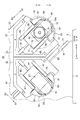
- FIG. 1 is a schematic front view of a circular saw machine according to an embodiment of the present invention.
- FIG. 2 is an enlarged view of a main part of the circular saw machine according to the embodiment of the present invention.
- FIG. 3 is a diagram showing a main part of the embodiment of the present invention, and shows a state in which the front side of the case body is opened by the case lid.
- FIG. 4 is an enlarged view taken along line IV-IV in FIG.
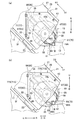
- FIGS. 5A and 5B are diagrams for explaining the operation of the movable saw blade guide set and the like according to the embodiment of the present invention.
- FIG. 6 is a diagram showing a main part of a first modification of the embodiment of the present invention, and shows a state in which the front side of the case body is opened by the case lid.
- FIGS. 7A and 7B are views for explaining the operation of the movable saw blade guide set and the like according to the first modification of the embodiment of the present invention.
- FIG. 8 is a diagram showing a main part of a second modification of the embodiment of the present invention, and shows a state where the front side of the case body is opened by the case lid.
- FIGS. 9A and 9B are diagrams for explaining the operation of the movable saw blade guide set and the like according to the second modification of the embodiment of the present invention.
- Providing means to provide indirectly through another member in addition to providing directly, and is synonymous with “providing”.
- the “radial direction” refers to the radial direction of the circular saw blade, and the “radial inner side” refers to the radial inner side of the circular saw blade.
- “Cutting position” refers to a position in the transport direction where cutting is performed. In the drawings, “FF” is the forward direction (conveying direction), “FR” is the backward direction, “L” is the left direction, “R” is the right direction, “U” is the upward direction, and “D”. Indicates the downward direction.
- the circular saw machine 1 performs a cutting process on a portion to be cut of a bar-shaped workpiece W positioned at a cutting position in a conveyance direction (forward direction).
- the structure of the circular saw machine 1 which concerns on embodiment of this invention is as follows.
- the circular saw 1 is provided on a base (bed) 3 extending in the transport width direction (left-right direction) orthogonal to the transport direction and on the left part of the upper surface of the base 3.
- the support frame 5 is provided.
- the support frame 5 has an inclined surface 5f that is inclined with respect to the horizontal direction (left-right direction).
- the base 3 includes a main body vice 7 for fixing the workpiece W to the base 3 on the upstream side (right upstream in the transport direction) of the cutting position on the upper surface (the upper surface of the base 3).
- the main body vise 7 has a vise bed (processing table) 9 that is provided on the upper surface of the base 3 and supports the workpiece W.
- the vise bed 9 includes a fixed vise jaw 11 on the left side of the upper surface (the upper surface of the vise bed 9).
- the vice bed 9 includes a movable vise jaw 13 that clamps the workpiece W in cooperation with the fixed vise jaw 11 on the upper surface thereof, and the movable vise jaw 13 is movable in the conveyance width direction.
- the vice bed 9 includes a hydraulic vise cylinder 15 that moves the movable vise jaw 13 in the conveyance width direction on the right side of the upper surface thereof.
- the base 3 includes a transport table (not shown) that supports the workpiece W so as to be movable in the transport direction on the rear side (the rear side of the base 3). Further, the transport table includes a transport vise (not shown) that transports the workpiece W in the transport direction at an appropriate position (appropriate position of the transport table).
- the support frame 5 includes a plurality of (only one shown) guide rails 17 extending in the inclined direction on the inclined surface 5f.
- the plurality of guide rails 17 include a machining head 21 having a rotatable circular saw blade 19 between them (between the plurality of guide rails 17).
- the circular saw blade 19 has a disc-shaped body portion 19b and a plurality (a large number) of cutting teeth 19t provided on the outer peripheral surface of the body portion 19b.
- a region located on the cutting direction D1 side in the circular saw blade 19 is a cutting region 19A that exhibits a cutting action.
- the machining head 21 is guided by a corresponding guide rail 17 on the lower surface (lower surface of the machining head 21) in the cutting direction (one side in the inclined direction) D1 and the opposite direction (the other side in the inclined direction) D2.
- a guided member 23 is provided.
- the machining head 21 is provided on the inclined surface 5f of the support frame 5 so as to be movable in the cutting direction D1 and the opposite direction D2 via the plurality of guide rails 17 and the plurality of guided members 23.
- the support frame 5 is provided with a machining head electric motor 25 as a machining head actuator for moving the machining head 21 in the cutting direction D1 and the opposite direction D2 on the support frame 5.
- the output shaft (not shown) of the machining head electric motor 25 is linked to the machining head 21 via a ball screw (not shown) and a nut member (not shown).
- a hydraulic machining head cylinder (not shown) may be used as the machining head actuator.
- the machining head 21 includes a movable box 27 provided on the inclined surface 5 f of the support frame 5 so as to be movable in the cutting direction D ⁇ b> 1 and the opposite direction D ⁇ b> 2, and below the movable box 27.
- a saw blade case 29 for accommodating a part of the circular saw blade 19.
- the saw blade case 29 is provided at a lower portion of the movable box 27 with a case main body 31 and a plurality of hinges (hinges) 33 provided on the case main body 31, and the front side of the case main body 31 can be opened and closed.
- a case lid (case cover) 35 is provided.
- the case lid 35 has a shape that approximates the case main body 31.
- the case main body 31 has a first rib 37 on the upper side of the inner side surface (the inner side surface of the case main body 31), and most of the first rib 37 is L-shaped when viewed from the front. .
- the case main body 31 has an insertion hole 39 at the center (the center of the case main body 31).
- the case lid 35 has a second rib 41 at the upper part of the inner side surface (the inner side surface of the case lid 35), and the front view of most of the second rib 41 is L-shaped. ing.
- the second rib 41 is integrally joined to the first rib 37 by a plurality of bolts 43.
- the case lid 35 is integrally joined to the case main body 31 by the plurality of bolts 43 with the front side of the case main body 31 closed.
- the movable box 27 includes a main shaft 45 inside the movable box 27 via a bearing 47 or the like, and the main shaft 45 can rotate around its axis (axis of the main shaft 45). ing.
- the front end portion of the main shaft 45 is inserted through an insertion hole 39.
- the circular saw blade 19 is fixed to the front end portion of the main shaft 45 by a bolt 51 with a pair of mounting flanges (mounting plates) 49 interposed therebetween. ing.
- the movable box 27 is provided with an electric motor 53 for a saw blade for rotating the circular saw blade 19 at an upper portion thereof. Further, the output shaft (not shown) of the saw blade electric motor 53 is linked to the main shaft 45 via a gear mechanism (not shown) and a belt mechanism (not shown) provided in the movable box.
- the saw blade case 29 is a pair of fixed saw blades that guide the saw blade case 29 at appropriate positions (appropriate positions of the saw blade case 29) so as to sandwich the body portion 19b of the circular saw blade 19 on both sides of the cutting region 19A of the circular saw blade 19.
- a guide set 55 is provided.
- the pair of fixed saw blade guide sets 55 are separated in a direction perpendicular to the cutting direction D1.
- Each fixed saw blade guide set 55 is in contact with the first bracket 57 fixed to the inner surface of the case body 31 and the back surface of the body portion 19b of the circular saw blade 19 provided at the tip of the first bracket 57.
- First fixed insert 59 is made of a hard material such as carbide.
- each fixed saw blade guide set 55 is provided on the surface of the second bracket 61 fixed to the inner surface of the case lid 35 and the body 19b of the circular saw blade 19 provided at the tip of the second bracket 61. It has the 2nd fixed insert 63 which can contact.
- the second fixed insert 63 is made of, for example, a hard material such as cemented carbide.
- the case main body 31 includes a pair of first slide guides 65 extending in the cutting direction D1 on the inner side surface (inner side surface of the case main body 31), and each first slide guide 65 has an L-shaped cross section. It has become.
- the case lid 35 includes a pair of second slide guides 67 extending in the cutting direction D1 on its inner side surface (inner side surface of the case lid 35). It has a letter shape.
- the saw blade case 29 has a body portion 19b of the circular saw blade 19 between the pair of fixed saw blade guide sets 55 on the radially inner side of the cutting area 19A of the circular saw blade 19 (the radially inner side of the circular saw blade 19).
- a movable saw blade guide set 69 is provided for guiding so as to be sandwiched.
- the movable saw blade guide set 69 is movable in the cutting direction D1 and the opposite direction D2 via the pair of first slide guides 65 and the pair of second slide guides 67.
- the movable saw blade guide set 69 has a first movable plate 71 provided on the inner surface of the case body 31 so as to be movable in the cutting direction D1 and the opposite direction D2 via a pair of first slide guides 65.
- the first movable plate 71 is formed with a first notch 73 for inserting the mounting flange 49, and the first movable plate 71 is not in contact with the mounting flange 49.
- the movable saw blade guide set 69 has a first movable insert 75 that is provided at the tip of the first movable plate 71 and that can contact the back surface of the body 19 b of the circular saw blade 19.
- the first movable insert 75 is made of, for example, a hard material such as cemented carbide.
- the movable saw blade guide set 69 has a second movable plate 77 provided on the inner surface of the case lid 35 through a pair of second slide guides 67 so as to be movable in the cutting direction D1 and the opposite direction D2.
- the second movable plate 77 is formed with a second notch 79 for inserting the mounting flange 49, and the second movable plate 77 is not in contact with the mounting flange 49.
- the movable saw blade guide set 69 has a second movable insert 81 that is provided at the tip of the second movable plate 77 and can contact the surface of the body 19 b of the circular saw blade 19.
- the 2nd movable insert 81 consists of hard materials, such as super hard, for example.
- the case main body 31 includes a first stopper 83 that restricts the movement of the first movable plate 71 in the cutting direction D1 at an appropriate position on the inner side surface (the inner side surface of the case main body 31).
- the case body 31 includes a first spring 85 as a first urging member for urging the first movable plate 71 in the cutting direction D1 (on the first stopper 83 side) at the upper part of the inner side surface.
- the case lid 35 includes a second stopper 87 that regulates the movement of the second movable plate 77 in the cutting direction D1 at an appropriate position on the inner side surface (the inner side surface of the case lid 35).
- the case lid 35 includes a second spring 89 as a second urging member that urges the second movable plate 77 in the cutting direction D1 (second stopper 87 side) at the upper part of the inner side surface thereof.
- the saw blade case 29 includes stoppers 83 and 87 that restrict the movement of the movable saw blade guide set 69 in the cutting direction D1 at an appropriate position on the inner side surface (the inner screen of the saw blade case 29).
- the saw blade case 29 includes springs 85 and 89 as biasing members that bias the movable saw blade guide set 69 in the cutting direction D1 at the upper part of the inner side surface thereof.
- the movable saw blade guide set 69 is moved in the cutting direction D1 to a part of the fixed saw blade guide set 55 (the first bracket 57 and the second bracket 61). You may add the function to regulate.
- the movable saw blade guide set 69 is attached with the springs 85 and 89 while maintaining a predetermined contact state when the circular saw blade 19 is cut into the workpiece W. It is configured to move relative to the machining head 21 in the opposite direction D2 while resisting the force.
- the predetermined contact state is a state in which the first movable insert 75 and the second movable insert 81 are in contact with the workpiece W, as well as a contact member provided in the movable saw blade guide set 69 ( (Not shown) includes a state in which the workpiece W or a fixed portion such as the fixed vise jaw 11 is in contact with the fixed portion.
- the second movable plate 77 may be integrally connected to the first movable plate 71 by a connection pin (not shown) or the like. In this case, any one of the first spring 85 and the second spring 89 may be omitted.
- the workpiece W After carrying the workpiece W into the conveyance table, the workpiece W is conveyed in the conveyance direction by the conveyance vise, and the cut portion of the workpiece W is positioned at the cutting position. Then, by moving the movable vise jaw 13 to the left by driving the vise cylinder 15, the work W is clamped by the cooperation of the fixed vise jaw 11 and the movable vise jaw 13. Thereby, the workpiece W can be fixed to the base 3.
- the circular saw blade 19 is rotated through the gear mechanism and the belt mechanism by driving the electric motor 53 for saw blade. Then, the machining head 21 is moved in the cutting direction D ⁇ b> 1 by driving the machining head electric motor 25. Thereby, it can cut
- the movable saw blade guide set 69 is in the radial direction of the cutting region 19A in the circular saw blade 19 until the circular saw blade 19 starts to cut into the workpiece W (immediately after the start of cutting). It guides so that the trunk
- the movable saw blade guide set 69 resists the urging force of the springs 85 and 89 while maintaining a predetermined contact state. It moves relative to the machining head 21 in the opposite direction D2. Thereby, the movable saw blade guide set 69 does not interfere with the cutting process.
- the machining head 21 After cutting, the machining head 21 is moved in the opposite direction D2 by driving the machining head electric motor 25. Then, the machining head 21 moves away from the workpiece W, and the movable saw blade guide set 69 moves relative to the machining head 21 in the cutting direction D1 by the urging force of the springs 85 and 89. Thereby, the process head 21 and the movable saw blade guide set 69 can be returned to the state before the cutting process.
- a plurality of products can be taken out from the workpiece W by cutting a plurality of parts to be cut of the workpiece W.
- the swing of the circular saw blade 19 when the circular saw blade 19 enters the workpiece W can be suppressed regardless of the width of the workpiece W. Therefore, according to the embodiment of the present invention, the cutting accuracy of the cut surface of the workpiece W can be improved by suppressing the bending of the circular saw blade 19 during the cutting processing regardless of the width of the workpiece W.
- the springs 85 and 89 provided on the upper part of the inner surface of the saw blade case 29 are omitted.
- the case body 31 has a first movable plate as an actuator for the first movable plate that moves the first movable plate 71 relative to the machining head 21 in the cutting direction D1 and the opposite direction D2 at the upper part of the inner side surface.
- Cylinder 91 is provided.
- the case lid 35 has a second movable plate as an actuator for a second movable plate that moves the second movable plate 77 relative to the machining head 21 in the cutting direction D1 and the opposite direction D2 at the upper part of the inner surface thereof.
- Cylinder 93 is provided.
- the saw blade case 29 is provided with a first movable plate cylinder 91 and a second movable plate cylinder 93 in place of the springs 85 and 89 at the upper part of the inner surface thereof.
- the movable saw blade guide set 69 is cut by the circular saw blade 19 until the circular saw blade 19 starts to cut into the workpiece W. It guides so that the trunk
- the movable saw blade guide set 69 (the first saw blade 91) is driven by the driving of the first movable plate cylinder 91 and the second movable plate cylinder 93.
- the movable plate 71 and the second movable plate 77) are moved relative to the machining head 21 in the opposite direction D2.
- the 1st movable insert 75 and the 2nd movable insert 81 do not contact
- the movable saw blade guide set 69 does not interfere with the cutting process.
- the movable saw blade guide set 69 (first movable plate 71 and second movable plate 77) is moved to the machining head 21 in the cutting direction D1 by driving the first movable plate cylinder 91 and the second movable plate cylinder 93. Move relative to it. Thereby, the movable saw blade guide set 69 can be returned to the state before the cutting process.
- the second movable plate 77 is integrally connected to the first movable plate 71 when the front side of the case body 31 is closed by the case lid 35, the first movable plate cylinder 91 and Any one of the second movable plate cylinders 93 may be omitted.
- the movable saw blade guide set 69 is divided in a direction orthogonal to the cutting direction D1.
- the movable saw blade guide set 69 is composed of a pair of divided saw blade guide sets 69S divided in the orthogonal direction.
- the first movable plate 71 includes a pair of divided movable plates 71S divided in the orthogonal direction.
- the 1st movable insert 75 is comprised by a pair of division
- the second movable plate 77 includes a pair of divided movable plates 77S divided in the orthogonal direction.
- the second movable insert 81 includes a pair of divided movable inserts 81S divided in the orthogonal direction.
- each divided movable plate 71S in the cutting direction D1 is restricted by a first stopper 83 provided at an appropriate position on the inner side surface of the case body 31.
- Each split movable plate 71 ⁇ / b> S is biased in the cutting direction D ⁇ b> 1 (first stopper 83 side) by a first spring 85 provided at the upper part of the inner side surface of the case body 31.
- the movement of each divided movable plate 77 ⁇ / b> S in the cutting direction D ⁇ b> 1 is restricted by a second stopper 87 provided at an appropriate position on the inner surface of the case lid 35.
- Each split movable plate 77S is urged in the cutting direction D1 (second stopper 87 side) by a second spring 89 provided at the upper part of the inner side surface of the case lid 35.
- the movable saw blade guide set 69 is cut by the circular saw blade 19 until the circular saw blade 19 starts to cut into the workpiece W. It guides so that the trunk
- the present invention is not limited to the description of the above-described embodiment, and can be implemented in various modes as follows.
- the cutting direction D1 of the machining head 21 may be a horizontal direction or a vertical direction (vertical direction) instead of a direction inclined with respect to the horizontal direction.
- the fixed saw blade guide set 55 may be omitted from the configuration of the circular saw machine 1.
- the scope of rights encompassed by the present invention is not limited to the above-described embodiment.
Abstract
L'invention concerne une machine à scier circulaire permettant de supprimer la courbure pendant la découpe d'une lame de scie circulaire (19) pendant un processus de découpe et d'augmenter la précision d'usinage sur la surface de découpe d'une pièce de travail (W), quelle que soit la largeur de la pièce de travail (W). La machine à scier circulaire (1) comprend : une tête d'usinage (21) ayant la lame de scie circulaire (19), la tête d'usinage (21) étant apte à bouger dans une direction d'incision (D1) et la direction opposée (D2) et étant apte à tourner ; et un ensemble de guidage de lame de scie mobile (69) prévu sur la tête d'usinage (21) de manière à pouvoir bouger dans la direction d'incision (D1) et la direction opposée (D2), l'ensemble de guidage de lame de scie mobile (69) effectuant un guidage de manière à enserrer une section de corps (19b) de la lame de scie circulaire (19) sur le côté interne dans la direction radiale d'une section de détourage (19A) de la lame de scie circulaire (19). L'ensemble de guidage de lame de scie mobile (69) est conçu de manière à être relié au mouvement de la tête d'usinage (21) dans la direction d'incision (D1) lorsque l'incision de la pièce de travail (W) se produit et à bouger par rapport à la tête d'usinage dans la direction opposée (D2).
Priority Applications (3)
| Application Number | Priority Date | Filing Date | Title |
|---|---|---|---|
| CN201680071805.2A CN108367368B (zh) | 2015-12-09 | 2016-11-30 | 能够抑制圆锯刀振动的圆锯床 |
| EP16872878.0A EP3388176B1 (fr) | 2015-12-09 | 2016-11-30 | Machine à scier circulaire capable de supprimer l'oscillation de la lame de scie circulaire |
| US16/060,613 US10875107B2 (en) | 2015-12-09 | 2016-11-30 | Circular saw machine capable of suppressing runout of circular saw blade |
Applications Claiming Priority (2)
| Application Number | Priority Date | Filing Date | Title |
|---|---|---|---|
| JP2015239901A JP6141951B1 (ja) | 2015-12-09 | 2015-12-09 | 丸鋸盤 |
| JP2015-239901 | 2015-12-09 |
Publications (1)
| Publication Number | Publication Date |
|---|---|
| WO2017098979A1 true WO2017098979A1 (fr) | 2017-06-15 |
Family
ID=59012052
Family Applications (1)
| Application Number | Title | Priority Date | Filing Date |
|---|---|---|---|
| PCT/JP2016/085549 WO2017098979A1 (fr) | 2015-12-09 | 2016-11-30 | Machine à scier circulaire dans laquelle l'oscillation de la lame de scie circulaire peut être supprimée |
Country Status (6)
| Country | Link |
|---|---|
| US (1) | US10875107B2 (fr) |
| EP (1) | EP3388176B1 (fr) |
| JP (1) | JP6141951B1 (fr) |
| CN (1) | CN108367368B (fr) |
| TW (1) | TWI621493B (fr) |
| WO (1) | WO2017098979A1 (fr) |
Cited By (1)
| Publication number | Priority date | Publication date | Assignee | Title |
|---|---|---|---|---|
| EP3479943A1 (fr) * | 2017-11-02 | 2019-05-08 | F.O.M. Industrie S.r.l. | Machine de découpe de barres de section, fabriquées en particulier en aluminium, alliages légers, pvc ou analogues |
Families Citing this family (2)
| Publication number | Priority date | Publication date | Assignee | Title |
|---|---|---|---|---|
| JP7274266B2 (ja) | 2017-05-26 | 2023-05-16 | 日東電工株式会社 | 磁石の製造方法 |
| CN113909561B (zh) * | 2021-10-27 | 2022-08-30 | 江苏恒力组合机床有限公司 | 一种钢轨数控锯切系统 |
Citations (8)
| Publication number | Priority date | Publication date | Assignee | Title |
|---|---|---|---|---|
| US2589309A (en) * | 1946-08-27 | 1952-03-18 | Ralph R Roemer | Circular saw safety guard |
| US2941451A (en) * | 1956-05-02 | 1960-06-21 | Hughes Aircraft Co | Cutter support |
| EP0016688A1 (fr) * | 1979-03-23 | 1980-10-01 | Graniterie Petitjean Fils | Dispositif stabilisateur pour un disque diamanté rotatif dans une machine à travailler la pierre |
| JPH02239901A (ja) * | 1989-03-14 | 1990-09-21 | Fuji Kogyo Kk | 丸鋸盤における振れ止装置 |
| JPH0416302A (ja) * | 1990-05-09 | 1992-01-21 | Ishita:Kk | 製材装置 |
| JPH07227714A (ja) * | 1994-02-17 | 1995-08-29 | Kitagawa Denki:Kk | 丸鋸切断機 |
| WO2013015042A1 (fr) * | 2011-07-27 | 2013-01-31 | 兼房株式会社 | Machine à découper |
| JP2013215877A (ja) * | 2012-11-29 | 2013-10-24 | Washio Junko | 鋸刃支持装置及び鋸盤による切断方法 |
Family Cites Families (15)
| Publication number | Priority date | Publication date | Assignee | Title |
|---|---|---|---|---|
| BE571800A (fr) * | 1957-10-07 | |||
| DE2043599B2 (de) * | 1970-09-03 | 1972-08-31 | Trennjäger Maschinenfabrik, 5350 Euskirchen | Metallkaltsaege |
| DE2646515A1 (de) * | 1976-10-15 | 1978-04-20 | Leopold Jaegers | Fuehrung fuer ein saegeblatt |
| SE416322B (sv) * | 1978-05-08 | 1980-12-15 | Tord Erik Birger Eriksson | Asfaltskerare |
| JPS5837541Y2 (ja) | 1979-02-06 | 1983-08-24 | 株式会社アマダ | 帯鋸刃案内装置 |
| DE3239986A1 (de) * | 1982-10-28 | 1984-05-03 | Robert Bosch Gmbh, 7000 Stuttgart | Handwerkzeugmaschine mit einem kreisscheibenfoermigen werkzeug |
| US5142825A (en) * | 1991-04-25 | 1992-09-01 | Floyd Kenneth R | Hand-held elongated stock material cutter |
| JP2781364B2 (ja) | 1995-09-22 | 1998-07-30 | 津根精機株式会社 | 丸鋸切断機 |
| US6722046B2 (en) * | 2001-09-04 | 2004-04-20 | Ben L Evenson | Portable forward cutting power saw |
| CA2448479C (fr) * | 2002-11-12 | 2009-05-05 | Makita Corporation | Outils mecaniques |
| CN102407383B (zh) * | 2010-09-20 | 2013-08-07 | 力山工业股份有限公司 | 锯片垂直升降的切割机 |
| CN102407381B (zh) * | 2010-09-21 | 2014-06-04 | 苏州宝时得电动工具有限公司 | 便携式切割机 |
| DE102011050189A1 (de) | 2011-05-06 | 2012-11-08 | Herbert Arnold Gmbh & Co. Kg | Stabilisierungsvorrichtung für eine Trennscheibe |
| JP5177779B1 (ja) * | 2012-04-06 | 2013-04-10 | 鷲尾 潤子 | 鋸刃支持装置及び鋸盤による切断方法 |
| CN203992635U (zh) * | 2014-06-06 | 2014-12-10 | 上海通用汽车有限公司 | 锯床安全保护装置 |
-
2015
- 2015-12-09 JP JP2015239901A patent/JP6141951B1/ja active Active
-
2016
- 2016-11-30 US US16/060,613 patent/US10875107B2/en active Active
- 2016-11-30 WO PCT/JP2016/085549 patent/WO2017098979A1/fr active Application Filing
- 2016-11-30 EP EP16872878.0A patent/EP3388176B1/fr active Active
- 2016-11-30 CN CN201680071805.2A patent/CN108367368B/zh active Active
- 2016-12-08 TW TW105140635A patent/TWI621493B/zh active
Patent Citations (8)
| Publication number | Priority date | Publication date | Assignee | Title |
|---|---|---|---|---|
| US2589309A (en) * | 1946-08-27 | 1952-03-18 | Ralph R Roemer | Circular saw safety guard |
| US2941451A (en) * | 1956-05-02 | 1960-06-21 | Hughes Aircraft Co | Cutter support |
| EP0016688A1 (fr) * | 1979-03-23 | 1980-10-01 | Graniterie Petitjean Fils | Dispositif stabilisateur pour un disque diamanté rotatif dans une machine à travailler la pierre |
| JPH02239901A (ja) * | 1989-03-14 | 1990-09-21 | Fuji Kogyo Kk | 丸鋸盤における振れ止装置 |
| JPH0416302A (ja) * | 1990-05-09 | 1992-01-21 | Ishita:Kk | 製材装置 |
| JPH07227714A (ja) * | 1994-02-17 | 1995-08-29 | Kitagawa Denki:Kk | 丸鋸切断機 |
| WO2013015042A1 (fr) * | 2011-07-27 | 2013-01-31 | 兼房株式会社 | Machine à découper |
| JP2013215877A (ja) * | 2012-11-29 | 2013-10-24 | Washio Junko | 鋸刃支持装置及び鋸盤による切断方法 |
Non-Patent Citations (1)
| Title |
|---|
| See also references of EP3388176A4 * |
Cited By (1)
| Publication number | Priority date | Publication date | Assignee | Title |
|---|---|---|---|---|
| EP3479943A1 (fr) * | 2017-11-02 | 2019-05-08 | F.O.M. Industrie S.r.l. | Machine de découpe de barres de section, fabriquées en particulier en aluminium, alliages légers, pvc ou analogues |
Also Published As
| Publication number | Publication date |
|---|---|
| EP3388176A1 (fr) | 2018-10-17 |
| TW201726284A (zh) | 2017-08-01 |
| TWI621493B (zh) | 2018-04-21 |
| CN108367368A (zh) | 2018-08-03 |
| EP3388176B1 (fr) | 2020-09-02 |
| EP3388176A4 (fr) | 2019-08-21 |
| JP6141951B1 (ja) | 2017-06-07 |
| JP2017104929A (ja) | 2017-06-15 |
| US20180369938A1 (en) | 2018-12-27 |
| US10875107B2 (en) | 2020-12-29 |
| CN108367368B (zh) | 2020-01-07 |
Similar Documents
| Publication | Publication Date | Title |
|---|---|---|
| WO2017098979A1 (fr) | Machine à scier circulaire dans laquelle l'oscillation de la lame de scie circulaire peut être supprimée | |
| US9789625B2 (en) | Separating device for a machine tool | |
| CN205414573U (zh) | 金属材料切割机 | |
| US20150059548A1 (en) | Cutting devices | |
| JP2018144208A (ja) | 両頭平面研削盤および研削方法 | |
| US20200238562A1 (en) | Double arbor vertical shape saw | |
| JP2006326809A (ja) | 丸鋸切断機およびそのワーク固定装置ならびにそのワーク固定方法 | |
| JP2017127972A (ja) | 丸鋸盤 | |
| EP3415293A1 (fr) | Scie à onglet | |
| JP2017071028A (ja) | 帯鋸盤 | |
| JP2015037817A (ja) | 両頭側面フライス盤 | |
| JP2018051695A (ja) | 鋸盤 | |
| WO2020038370A1 (fr) | Mécanisme d'arrêt et machine de coupe | |
| KR100793381B1 (ko) | 파이프 커팅장치 | |
| JP6948985B2 (ja) | 工作機械のカバー装置 | |
| TWI712461B (zh) | 差動齒輪箱加工用的刀具、差動齒輪箱的加工機以及差動齒輪箱的加工方法 | |
| JP2017001123A (ja) | 機械加工装置及び機械加工方法 | |
| KR101791178B1 (ko) | 단추 제조장치 | |
| JP6654403B2 (ja) | 加工装置 | |
| TWM603829U (zh) | 餘料切除裝置 | |
| KR20150031866A (ko) | 금속판 절단장치 | |
| KR102104787B1 (ko) | 라우터 세트 | |
| JP5716366B2 (ja) | 卓上切断機 | |
| CN210387785U (zh) | 具有自动切割落料功能的车床 | |
| US10625394B1 (en) | Blade stop devices and methods |
Legal Events
| Date | Code | Title | Description |
|---|---|---|---|
| 121 | Ep: the epo has been informed by wipo that ep was designated in this application |
Ref document number: 16872878 Country of ref document: EP Kind code of ref document: A1 |
|
| NENP | Non-entry into the national phase |
Ref country code: DE |
|
| WWE | Wipo information: entry into national phase |
Ref document number: 2016872878 Country of ref document: EP |
|
| ENP | Entry into the national phase |
Ref document number: 2016872878 Country of ref document: EP Effective date: 20180709 |