WO2017098841A1 - 風量増大ユニットおよびそれを備えた熱交換装置 - Google Patents
風量増大ユニットおよびそれを備えた熱交換装置 Download PDFInfo
- Publication number
- WO2017098841A1 WO2017098841A1 PCT/JP2016/082795 JP2016082795W WO2017098841A1 WO 2017098841 A1 WO2017098841 A1 WO 2017098841A1 JP 2016082795 W JP2016082795 W JP 2016082795W WO 2017098841 A1 WO2017098841 A1 WO 2017098841A1
- Authority
- WO
- WIPO (PCT)
- Prior art keywords
- wall surface
- wind
- flow path
- air volume
- increasing unit
- Prior art date
- Legal status (The legal status is an assumption and is not a legal conclusion. Google has not performed a legal analysis and makes no representation as to the accuracy of the status listed.)
- Ceased
Links
Images


Classifications
-
- B—PERFORMING OPERATIONS; TRANSPORTING
- B60—VEHICLES IN GENERAL
- B60K—ARRANGEMENT OR MOUNTING OF PROPULSION UNITS OR OF TRANSMISSIONS IN VEHICLES; ARRANGEMENT OR MOUNTING OF PLURAL DIVERSE PRIME-MOVERS IN VEHICLES; AUXILIARY DRIVES FOR VEHICLES; INSTRUMENTATION OR DASHBOARDS FOR VEHICLES; ARRANGEMENTS IN CONNECTION WITH COOLING, AIR INTAKE, GAS EXHAUST OR FUEL SUPPLY OF PROPULSION UNITS IN VEHICLES
- B60K11/00—Arrangement in connection with cooling of propulsion units
- B60K11/02—Arrangement in connection with cooling of propulsion units with liquid cooling
- B60K11/04—Arrangement or mounting of radiators, radiator shutters, or radiator blinds
-
- F—MECHANICAL ENGINEERING; LIGHTING; HEATING; WEAPONS; BLASTING
- F28—HEAT EXCHANGE IN GENERAL
- F28F—DETAILS OF HEAT-EXCHANGE AND HEAT-TRANSFER APPARATUS, OF GENERAL APPLICATION
- F28F13/00—Arrangements for modifying heat-transfer, e.g. increasing, decreasing
- F28F13/06—Arrangements for modifying heat-transfer, e.g. increasing, decreasing by affecting the pattern of flow of the heat-exchange media
Definitions
- the present disclosure relates to an air volume increasing unit that increases the air volume using the Coanda effect, and a heat exchange apparatus including the air volume increasing unit.
- a cooling device described in Patent Document 1 has been known as an air volume increasing unit using the Coanda effect.
- the cooling device described in Patent Document 1 is installed on the front side of a heat exchanger of a vehicle.
- the cooling device includes a header and a plurality of ducts.
- the header extends in the width direction of the vehicle.
- the plurality of ducts extend vertically from the header.
- Each of the plurality of ducts is provided with an air blowing portion that blows air toward the heat exchanger. The air blown out from the air blowing portion causes the Coanda effect.
- the air blown out from the air blowing section is supplied from a separate blower. That is, a separate blower blows air to the header, and the blown air is distributed to each duct by the header and blown out from the air blowing portion of each duct.
- Patent Document 1 can produce an effect of increasing the air volume, but for that purpose, a blower is required separately from the air volume increasing unit as described above. That is, there is a restriction that a separate blower is required to increase the air volume. As a result of detailed investigations by the inventors, this has been found.
- the present disclosure in the air volume increasing unit disposed in the wind flow of the traveling wind, compares the air volume on the downstream side of the air flow of the air volume increasing unit as compared to the case where the air volume increasing unit is not provided.
- the purpose is to increase.
- the air volume increasing unit of the present disclosure includes: An air volume increasing unit arranged in a wind flow of traveling wind flowing in one direction as the vehicle travels, An opening that is open to face the traveling wind, and a flow path forming portion that includes a flow path forming wall that extends from the opening toward the downstream side of the wind flow of the traveling wind along one direction. , A downstream extension part extending from the flow path forming part to the wind flow downstream side along the one direction, and The flow path forming wall forms the traveling air flow path so as to surround the traveling air flow path through which the traveling wind flowing in from the opening flows.
- the flow path forming portion and the downstream extending portion as a whole form a plate shape whose thickness direction is the direction intersecting the one direction, and the first outer wall surface and the plate shape as a wall surface on one side of the plate shape.
- Forming a second outer wall surface as a wall surface on the other surface side Each of the first outer wall surface and the second outer wall surface flows along the wall surface wind including the traveling wind.
- the flow path forming portion has a through hole penetrating the flow path forming wall from the first outer wall surface into the travel wind flow path, and guides the travel wind facing the travel wind flow path and flowing in the travel wind flow path to the through hole.
- a wind guide inner wall surface is formed,
- the through hole is The opening area of the through hole is formed to be smaller than the opening area of the opening,
- the traveling wind flowing out from the traveling wind passage through the through hole is merged with the wall surface wind along the first outer wall surface at a flow velocity faster than the wall surface wind.
- the through hole formed in the flow path forming portion causes the traveling wind flowing out from the traveling wind channel through the through hole to flow faster than the wall surface wind along the first outer wall surface than the wall surface wind. Therefore, the wall surface wind along the first outer wall surface can be increased by the Coanda effect. As a result, the surrounding air is entrained in the traveling wind included in the wall wind, and the entrained air flows as the wall wind together with the traveling wind. Therefore, it is possible to increase the air volume on the downstream side of the air flow of the air volume increasing unit as compared with the case where the air volume increasing unit is not provided.
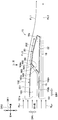
- FIG. 2 is a cross-sectional view of the air volume increasing unit shown in FIG. 1 cut along a cross section perpendicular to the vehicle width direction in the first embodiment, in other words, a cross-sectional view taken along the line II-II of FIG.
- FIG. 3 is a plan view of a single air volume increasing unit as viewed from above the vehicle in the first embodiment, that is, a view taken in the direction of arrow III in FIG. 2.
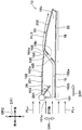
- FIG. 2 is a cross-sectional view taken along the line II-II of FIG. 1 showing a single air volume increasing unit in the second embodiment, corresponding to FIG. 2 of the first embodiment.
- a plurality of air volume increasing units 10 of the present embodiment are provided in the vehicle as shown in FIG.
- the air volume increasing unit 10 is disposed in the wind flow of the traveling wind indicated by the arrow FLv.
- the traveling wind (in other words, vehicle speed wind) flows in one direction DRf as the vehicle travels. That is, the one direction DRf is a traveling wind mainstream direction DRf which is the direction of the mainstream of traveling wind.
- the air volume increasing unit 10 is disposed in the engine room of the vehicle together with the radiator 12.
- the radiator 12 is a heat exchanger through which the traveling wind passes in the traveling wind main flow direction DRf, and heat is exchanged between the engine cooling water that is a heat exchange medium and the traveling wind to dissipate heat from the engine cooling water to the traveling wind.
- Each of the plurality of air volume increasing units 10 has a plate shape and is installed on the upstream side of the wind flow with respect to the radiator 12 in the traveling wind main flow direction DRf.
- the air volume increasing unit 10 and the radiator 12 constitute a heat exchange device 14 for cooling the engine coolant.
- each arrow DR1, DR2, DR3 of FIG. 1 shows the direction of the vehicle in which the air volume increasing unit 10 is mounted. That is, the double-ended arrow DR1 in FIG. 1 indicates the vehicle longitudinal direction DR1, the double-ended arrow DR2 indicates the vehicle vertical direction DR2, and the double-ended arrow DR3 indicates the vehicle left-right direction DR3, that is, the vehicle width direction DR3.
- These three directions DR1, DR2, and DR3 are directions intersecting each other, strictly, directions orthogonal to each other.
- the traveling wind main flow direction DRf is parallel to the vehicle longitudinal direction DR1. That is, the wind flow upstream side in the traveling wind main flow direction DRf is the vehicle front side, and the wind flow downstream side opposite to the wind flow upstream side is the vehicle rear side.
- the air volume increasing unit 10 includes a flow path forming portion 16 and a downstream extending portion 18. And the flow path formation part 16 and the downstream extension part 18 are connected in series in order of the flow path formation part 16 and the downstream extension part 18 from the wind flow upstream of the traveling wind main flow direction DRf.
- the flow path forming portion 16 includes an opening 161 and a flow path forming wall 162.
- the opening 161 constitutes an edge on the upstream side of the wind flow in the traveling wind main flow direction DRf in the air volume increasing unit 10.
- the opening 161 constitutes an edge on the upstream side of the wind flow in the traveling wind main flow direction DRf in the flow path forming unit 16.
- the opening part 161 is opened so that the driving
- the flow path forming wall 162 extends from the opening 161 to the downstream side of the wind flow of the traveling wind along the traveling wind main flow direction DRf.
- the flow path forming wall 162 forms a traveling air flow path 163 through which the traveling wind flowing in from the opening 161 flows inside the flow path forming wall 162. That is, the flow path forming wall 162 forms the traveling wind channel 163 so as to surround the traveling wind channel 163. Therefore, the flow path forming wall 162 has an upper side wall 162a that covers the upper side of the traveling wind path 163 in the vehicle vertical direction DR2, and a lower side wall 162b that covers the lower side of the traveling wind path 163. At the same time, the flow path forming wall 162 has one side wall 162c that covers one of the traveling wind flow paths 163 and the other side wall 162d that covers the other of the traveling wind flow paths 163 in the vehicle width direction DR3.
- the cross section of the traveling wind passage 163 orthogonal to the traveling wind main flow direction DRf has a flat shape with the vehicle vertical direction DR2 as a short direction, for example.
- the downstream extending portion 18 is a portion extending from the flow path forming portion 16 to the downstream side of the wind flow of the traveling wind along the traveling wind main flow direction DRf.
- the flow path forming portion 16 and the downstream extending portion 18 as a whole have a plate shape in which the vehicle vertical direction DR2 is the thickness direction DRt.
- the flow path forming portion 16 and the downstream extending portion 18 as a whole have a first outer wall surface 20 as a wall surface on the one surface side of the plate shape and a second wall surface on the other surface side of the plate shape.
- the outer wall surface 22 is formed.
- first outer wall surface 20 and the second outer wall surface 22 are formed over the entire length of the air volume increasing unit 10 in the vehicle longitudinal direction DR1.
- the first outer wall surface 20 is a side surface facing the vehicle upper side in the air volume increasing unit 10
- the second outer wall surface 22 is a side surface facing the vehicle lower side.
- the first outer wall surface 20 and the second outer wall surface 22 are provided so that the wall surface wind including the traveling wind flows along.
- the wall surface wind that flows along the first outer wall surface 20 among the wall surface winds is indicated by an arrow FL1
- the wall surface wind that flows along the second outer wall surface 22 is indicated by an arrow FL2.
- the wall surface wind includes, for example, air around the air volume increasing unit 10 caught in the traveling wind.
- the thickness direction DRt is the thickness direction of the entire flow path forming portion 16 and the downstream extending portion 18, and in short, is the thickness direction of the plate-shaped air volume increasing unit 10.
- a plurality of air volume increasing units 10 are provided so as to be stacked and spaced from each other in the thickness direction DRt of the air volume increasing unit 10.
- Each of the plurality of air volume increasing units 10 extends over the entire width of the air inflow surface 121 of the radiator 12 into which the traveling wind flows in the vehicle width direction DR3.
- FIG. 2 described above shows a virtual cross section along both the traveling wind mainstream direction DRf and the thickness direction DRt of the air volume increasing unit 10.
- the air volume increasing unit 10 has a cross-sectional shape such as a wing.
- the first outer wall surface 20 has a shape that is gently curved in a convex shape.
- the first outer wall surface 20 is such that the creeping length of the first outer wall surface 20 along the first outer wall surface 20 is longer than the creeping length of the second outer wall surface 22 along the second outer wall surface 22. Is formed. Thereby, the flow velocity of the air flowing along the first outer wall surface 20 can be made faster than the flow velocity of the air flowing along the second outer wall surface 22.
- the traveling air flow path 163 is formed as described above, but an air blowing hole 164 and an air guide inner wall surface 165 are also formed.
- the air blowing hole 164 is a through hole that penetrates the flow path forming wall 162 from the first outer wall surface 20 to the traveling wind flow path 163.
- the air blowing hole 164 is a through-hole penetrating the upper side wall 162 a of the flow path forming wall 162. Therefore, the air blowing hole 164 blows air out of the traveling air flow path 163 to the outside of the flow path forming unit 16.
- the air blowing hole 164 is provided on the first outer wall surface 20 side of the traveling wind passage 163, but is not provided on the second outer wall surface 22 side.
- the first outer wall surface 20 side of the traveling wind channel 163 in the thickness direction DRt of the air volume increasing unit 10 is opened to the outside of the channel forming unit 16 through the air blowing hole 164.
- the second outer wall surface 22 side of the traveling wind channel 163 is closed by the lower side wall 162b of the channel forming wall 162. As a result, the entire amount of the traveling wind that has flowed into the traveling wind channel 163 is blown out from the air blowing hole 164 to the outside of the channel forming unit 16.
- the opening area of the air blowing hole 164 is smaller than the opening area of the opening 161.
- the opening area of the air blowing hole 164 is a flow path cross-sectional area of the air blowing hole 164 as an air flow path in a cross section perpendicular to the air flow passing through the air blowing hole 164.
- the opening area of the opening 161 is a cross-sectional area of an opening 161a as an air flow path formed by the opening 161 in a cross section orthogonal to the air flow passing through the opening 161.
- the air blowing hole 164 causes the running wind flowing out from the running wind flow path 163 through the air blowing hole 164 as indicated by arrow FL3 to the wall surface along the first outer wall face 20 as indicated by arrow FL1. Merge at a flow rate faster than the wind.
- the air blowing hole 164 is formed in a slit shape having the vehicle width direction DR3 as a longitudinal direction and the vehicle longitudinal direction DR1 as a short direction. And the air blowing hole 164 is provided over the full width of the driving
- the air blowing hole 164 divides the first outer wall surface 20 into two regions 201 and 202.
- the two regions 201 and 202 are an upstream region 201 that occupies an upstream side of the air flow from the air blowing hole 164 in the traveling wind main flow direction DRf in the first outer wall surface 20, and a wind flow downstream of the air blowing hole 164. It is the downstream area 202 occupying the side.
- the upstream region 201 is included in the flow path forming unit 16.
- the downstream region 202 is included in the downstream extending portion 18.
- the first outer wall surface 20 and the second outer wall surface 22 when viewing the first outer wall surface 20 and the second outer wall surface 22 with respect to the air blowing hole 164, the first outer wall surface 20 and the second outer wall in the thickness direction DRt are located downstream of the air blowing hole 164 in the wind flow direction.
- the distance from the wall surface 22 in other words, the interval gradually decreases toward the downstream side of the wind flow.
- the air guide inner wall surface 165 of the flow path forming portion 16 faces the traveling wind flow path 163 at the end opposite to the opening 161 side of the traveling wind flow path 163 in the traveling wind main flow direction DRf. is doing.
- the wind guide inner wall surface 165 is comprised by the surface which continues without bending from the inner wall surface 162e of the lower side wall 162b which faces the driving
- the air guide inner wall surface 165 is an inclined surface inclined with respect to the thickness direction DRt of the air volume increasing unit 10. As the direction of the inclination, the air guide inner wall surface 165 is inclined so that the position closer to the air blowing hole 164 is shifted to the side away from the opening 161 in the traveling wind mainstream direction DRf. With such a configuration, the wind guide inner wall surface 165 guides the traveling wind flowing in the traveling wind channel 163 to the air blowing hole 164 as indicated by an arrow FL3.
- the downstream extending portion 18 has a hollow structure, and the air guide inner wall surface 165 is formed with a communication hole 18b that connects the internal space 18a of the downstream extending portion 18 and the traveling wind passage 163. Yes.
- the internal space 18a and the communication hole 18b of the downstream extending portion 18 are provided in response to a request for molding the air volume increasing unit 10, and may be omitted. Further, since the internal space 18a is not opened except for the communication hole 18b, there is almost no air flow through the communication hole 18b. Therefore, the communication hole 18b hardly affects the wind flow in the traveling wind channel 163 as indicated by the arrow FL3.
- the flow path forming portion 16 has a through-hole inner wall surface 166.
- the through-hole inner wall surface 166 is a wall surface facing the air outlet hole 164 on the downstream extension portion 18 side in the traveling wind main flow direction DRf.
- the through-hole inner wall surface 166 has a convexly curved shape in the cross section shown in FIG.
- the cross-sectional shape of the through-hole inner wall surface 166 is an arc shape.
- the through-hole inner wall surface 166 is curved so as to increase the width of the air blowing hole 164 along the first outer wall surface 20 closer to the outer edge 164a of the air blowing hole 164 in the cross section shown in FIG. Yes.
- the through-hole inner wall surface 166 is provided between the air guide inner wall surface 165 and the downstream region 202 of the first outer wall surface 20, and is bent to each of the air guide inner wall surface 165 and the downstream region 202. There is no continuous connection.
- the air blowing hole 164 formed in the flow path forming unit 16 shown in FIG. 2 allows the traveling wind flowing out from the traveling wind flow path 163 through the air blowing hole 164 to 1
- the wall surface wind along the outer wall surface 20 is merged at a faster flow velocity than the wall surface wind. Therefore, the wall surface wind along the first outer wall surface 20 can be increased by the Coanda effect.
- ambient air is entrained in the traveling wind included in the wall wind, and the entrained air flows as a wall wind along with the traveling wind. Therefore, it is possible to increase the air volume on the downstream side of the air flow of the air volume increasing unit 10 as compared with the case where the air volume increasing unit 10 is not provided.
- the traveling air is taken into the traveling air flow path 163 and flows out from the air outlet hole 164, thereby efficiently reducing the air volume on the downstream side of the air flow of the air volume increasing unit 10 without requiring a blower or the like. It can be increased.
- the traveling air flows directly into the traveling air passage 163 in the air volume increasing unit 10, there is an advantage that a blower for supplying air to the traveling air passage 163 is unnecessary. And since it does not have power parts, such as an air blower, it is possible to comprise the air volume increase unit 10 which was cheap and excellent in durability.
- the first outer wall surface 20 side of the traveling air flow path 163 in the thickness direction DRt of the air volume increasing unit 10 is connected to the flow path forming portion 16 via the air blowing hole 164. Is open to the outside.
- the second outer wall surface 22 side of the traveling wind channel 163 is closed by the lower side wall 162b of the channel forming wall 162. Therefore, compared to the configuration in which the second outer wall surface 22 side is also opened to the outside by some kind of hole, it is easy to increase the flow velocity of the traveling wind that blows out from the air blowing hole 164, and the Coanda effect that increases the flow velocity of the wall surface wind is greater. Easy to get.
- the first along the first outer wall surface 20 in the cross section shown in FIG. 2, which is a virtual cross section along both the traveling wind mainstream direction DRf and the thickness direction DRt of the air volume increasing unit 10, the first along the first outer wall surface 20.
- the creepage length of the first outer wall surface 20 is longer than the creepage length of the second outer wall surface 22 along the second outer wall surface 22. Accordingly, it is possible to cause the first outer wall surface 20 to act like the suction surface of the blade and the second outer wall surface 22 to act like the pressure surface of the blade.
- the Coanda is driven by the running wind that blows out from the air blowing hole 164 with respect to the wall surface wind on the first outer wall surface 20, which can have a high flow rate, out of the wall surface wind on the first outer wall surface 20 and the wall surface wind on the second outer wall surface 22.
- An effect can be produced.
- the flow velocity of the wall surface wind on the first outer wall surface 20 which can be higher than the wall surface wind on the second outer wall surface 22 can be further increased.
- the Coanda effect generated when the wall surface wind on the first outer wall surface 20 and the wall surface wind on the second outer wall surface 22 merge on the downstream side of the wind flow of the air volume increasing unit 10 can be increased.
- the wall surface wind on the first outer wall surface 20 is the wall surface wind along the first outer wall surface 20, and the wall surface wind on the second outer wall surface 22 is different. It is a wall surface wind along the second outer wall surface 22.
- the creepage length of the first outer wall surface 20 on the side where the air blowing holes 164 are provided is longer than the creepage length of the second outer wall surface 22 on the opposite side.
- the action of increasing the air volume by the Coanda effect is increased.
- the through-hole inner wall surface 166 has a convexly curved shape in the cross section shown in FIG.
- the through-hole inner wall surface 166 is provided between the air guide inner wall surface 165 and the downstream region 202 of the first outer wall surface 20, and bends to the air guide inner wall surface 165 and the downstream region 202, respectively. It is continuously connected without. Therefore, the traveling wind blown from the air blowing hole 164 can be smoothly merged with the wall surface wind on the first outer wall surface 22 along the inner wall surface 166 of the through hole.
- the distance between the first outer wall surface 20 and the second outer wall surface 22 in the thickness direction DRt on the downstream side of the air flow from the air blowing hole 164 is the wind speed.
- the downstream side is gradually smaller. Therefore, the wall surface wind that flows along the first outer wall surface 20 and the wall surface wind that flows along the second outer wall surface 22 can be smoothly merged on the downstream side of the wind flow of the air volume increasing unit 10.
- the wind flow downstream side in the traveling wind main flow direction DRf is the vehicle rear side. Therefore, the air volume increasing unit 10 can be easily mounted on the vehicle in the direction in which the opening 161 of the air volume increasing unit 10 opens facing the traveling wind.
- the air volume increasing unit 10 is installed on the upstream side of the wind flow in the traveling wind main flow direction DRf with respect to the radiator 12. Therefore, it is possible to increase the amount of air flowing into the radiator 12 as compared with the case where the air amount increasing unit 10 is not provided.
- a plurality of the air volume increasing units 10 are provided so as to be stacked and arranged with a mutual interval in the thickness direction DRt. Therefore, compared with the case where the air volume increasing unit 10 is used alone, the effect of increasing the air volume by the Coanda effect can be greatly obtained.
- the opening 161 is always open.
- the air volume increasing unit 10 of the present embodiment includes an opening / closing device 26 that opens and closes the opening 161, as shown in FIG.
- the opening / closing device 26 is a movable shutter provided in the opening 161.
- the opening / closing device 26 has a plate-like rotating door 261 that is rotated by, for example, an electric actuator (not shown). Then, the opening / closing device 26 opens and closes the opening 161 by the turning operation of the turning door 261.
- the air volume increasing unit 10 includes the opening / closing device 26 that opens and closes the opening 161. Therefore, the air volume on the downstream side of the air flow of the air volume increasing unit 10 can be increased or decreased by the opening / closing device 26.
- the traveling wind mainstream direction DRf is in a direction parallel to the vehicle front-rear direction DR1, but may not be parallel.
- the thickness direction DRt of the flow path forming portion 16 and the downstream extending portion 18 coincides with the vehicle vertical direction DR2, and thus is orthogonal to the traveling wind mainstream direction DRf. It is not necessary to be limited to being orthogonal to the mainstream direction DRf. For example, if the traveling wind passes between the plurality of air volume increasing units 10 efficiently and smoothly, the thickness direction DRt may be inclined to intersect with the traveling wind mainstream direction DRf.
- the air volume increasing unit 10 is arranged in the wind flow of the traveling wind and is not provided with a blower for blowing air, but is provided with the blower, The traveling wind may be increased by the blower.
- the air blowing hole 164 is formed on the first outer wall surface 20 side of the traveling air flow path 163 on the first outer wall surface 20 side and the second outer wall surface 22 side. However, it may be provided only on the second outer wall surface 22 side. Moreover, the air blowing hole 164 may be provided in both the 1st outer wall surface 20 side and the 2nd outer wall surface 22 side.
- the air volume increasing unit 10 is disposed on the upstream side of the wind flow in the traveling wind main flow direction DRf with respect to the radiator 12.
- positioned with respect to the radiator 12 in a wind flow downstream side can also be considered.
- the air volume increasing unit 10 is mounted on the vehicle together with the radiator 12, but may be provided independently of the radiator 12.
- the air volume increasing unit is arranged in the wind flow of the traveling wind flowing in one direction as the vehicle travels.
- the through hole merges the traveling wind flowing out from the through hole with the wall surface wind along the first outer wall surface at a flow rate faster than the wall surface wind.
- the first outer wall surface side of the traveling wind passage in the thickness direction is opened to the outside of the passage forming portion through the through hole, while the second outer wall surface of the traveling wind passage is provided.
- the side is closed by a flow path forming wall. Therefore, compared to a configuration in which the second outer wall surface side is also opened to the outside by some kind of hole, it is easy to increase the flow velocity of the traveling wind blowing from the through hole, and the Coanda effect that increases the flow velocity of the wall surface wind can be obtained more greatly. Easy.
- the creeping length of the first outer wall surface along the first outer wall surface is the second outer wall surface. It is longer than the creeping length of the second outer wall surface along. Accordingly, it is possible to cause the first outer wall surface to act like the suction surface of the blade and to cause the second outer wall surface to act like the pressure surface of the blade.
- the Coanda effect can be generated by the traveling wind blown from the through hole with respect to the wall surface wind on the first outer wall surface, which can be a high flow velocity, of the wall surface wind on the first outer wall surface and the wall surface wind on the second outer wall surface. it can.
- the flow velocity of the wall surface wind on the first outer wall surface that can be higher than the wall surface wind on the second outer wall surface can be further increased.
- the wall surface wind on the first outer wall surface (that is, the wall surface wind along the first outer wall surface) and the wall surface wind on the second outer wall surface increase in the air volume. It is possible to increase the Coanda effect that occurs when merging on the downstream side of the wind flow of the unit.
- the creepage length of the first outer wall surface on the side where the through hole is provided is longer than the creepage length of the second outer wall surface on the opposite side. Compared with the case where the creepage length is longer than the creepage length or when the creepage length is the same, the action of increasing the air volume by the Coanda effect is increased.
- the inner wall surface of the through hole has a convex curved shape in a virtual cross section along both the one direction and the thickness direction, and the inner wall surface of the wind guide and the first outer surface The wall surface is continuously connected to each of the regions included in the downstream extending portion. Therefore, the traveling wind blown from the through hole can be smoothly merged with the wall surface wind on the first outer wall surface along the inner wall surface of the through hole.
- the distance between the first outer wall surface and the second outer wall surface in the thickness direction on the downstream side of the wind flow from the through hole is smaller toward the downstream side of the wind flow. Therefore, the wall surface wind flowing along the first outer wall surface and the wall surface wind flowing along the second outer wall surface can be smoothly merged on the downstream side of the wind flow of the air volume increasing unit.
- the air volume increasing unit includes an opening / closing device that opens and closes the opening. Therefore, the air volume on the downstream side of the air flow of the air volume increasing unit can be increased or decreased by the opening / closing device.
- the wind flow downstream side in the one direction is the vehicle rear side. Therefore, the air volume increasing unit can be easily mounted on the vehicle in such a direction that the opening of the air volume increasing unit opens facing the traveling wind.
- the air volume increasing unit is installed on the upstream side of the wind flow in the one direction with respect to the heat exchanger. Therefore, it is possible to increase the amount of air flowing into the heat exchanger as compared with the case where the air amount increasing unit is not provided.
- a plurality of the air volume increasing units are provided so as to be stacked and spaced apart from each other in the thickness direction. Therefore, compared with the case where the air volume increasing unit is used alone, the effect of increasing the air volume by the Coanda effect can be greatly obtained.
Landscapes
- Engineering & Computer Science (AREA)
- Mechanical Engineering (AREA)
- Physics & Mathematics (AREA)
- Thermal Sciences (AREA)
- General Engineering & Computer Science (AREA)
- Chemical & Material Sciences (AREA)
- Combustion & Propulsion (AREA)
- Transportation (AREA)
- Cooling, Air Intake And Gas Exhaust, And Fuel Tank Arrangements In Propulsion Units (AREA)
- Air-Flow Control Members (AREA)
Abstract
風量増大ユニットにおいて流路形成部は、走行風に対向するように開口した開口部(161)、および、その開口部から走行風の風流れ下流側へ延設された流路形成壁(162)を含んで構成されている。また、下流側延設部は、流路形成部から風流れ下流側へ延設されている。流路形成壁は、開口部から流入した走行風が流れる走行風流路(163)を取り囲むようにしてその走行風流路を形成する。流路形成部および下流側延設部は全体として板状を成すと共に、一面側の第1外壁面(20)と他面側の第2外壁面(22)とを形成する。流路形成部には、第1外壁面から走行風流路内へと流路形成壁を貫通した貫通孔(164)が形成される。貫通孔は、その貫通孔の開口面積が開口部の開口面積よりも小さくなるように形成され、走行風流路から貫通孔を介して流出する走行風を、第1外壁面に沿った壁面風に対しその壁面風よりも速い流速で合流させる。
Description
本出願は、2015年12月9日に出願された日本特許出願番号2015-240493号に基づくもので、ここにその記載内容が参照により組み入れられる。
本開示は、コアンダ効果を利用して風量を増大させる風量増大ユニットと、それを備えた熱交換装置とに関するものである。
コアンダ効果を利用した風量増大ユニットとして、例えば特許文献1に記載された冷却装置が従来から知られている。この特許文献1に記載された冷却装置は、車両の熱交換器の前側に設置される。そして、その冷却装置は、ヘッダと複数のダクトとを備えている。そのヘッダは、車両の幅方向へ延びている。複数のダクトは、ヘッダから上下方向へそれぞれ延びている。また、複数のダクトにはそれぞれ、熱交換器に向けて空気を吹き出す空気吹出部が配設されている。この空気吹出部から吹き出る空気がコアンダ効果を生じさせる。
また、空気吹出部から吹き出る空気は、別体の送風機から供給される。すなわち、別体の送風機がヘッダへ送風し、その送風された空気はヘッダにてそれぞれのダクトへ分配されて各ダクトの空気吹出部から吹き出る。
特許文献1は、風量を増大させるという作用を生じることはできるが、そのためには、上述のように風量増大ユニットとは別に送風機が必要とされる。すなわち、風量増大のために別体の送風機を要するという制約があった。発明者らの詳細な検討の結果、このようなことが見出された。
本開示は上記点に鑑みて、走行風の風流れの中に配置される風量増大ユニットにおいて、風量増大ユニットの風流れ下流側における風量を、その風量増大ユニットが設けられていない場合に比して増加させることを目的とする。
上記目的を達成するため、本開示の1つの観点によれば、本開示の風量増大ユニットは、
車両走行に伴って一方向へ流れる走行風の風流れの中に配置される風量増大ユニットであって、
走行風に対向するように開口した開口部、および、その開口部から一方向に沿って走行風の風流れ下流側へ延設された流路形成壁を含んで構成された流路形成部と、
その流路形成部から上記一方向に沿って風流れ下流側へ延設された下流側延設部とを備え、
流路形成壁は、開口部から流入した走行風が流れる走行風流路を取り囲むようにしてその走行風流路を形成し、
流路形成部および下流側延設部は全体として、上記一方向に交差する方向を厚み方向とした板状を成すと共に、その板状の一面側の壁面としての第1外壁面とその板状の他面側の壁面としての第2外壁面とを形成し、
第1外壁面および第2外壁面にはそれぞれ、走行風を含む壁面風が沿って流れ、
流路形成部には、第1外壁面から走行風流路内へと流路形成壁を貫通した貫通孔と、走行風流路に面し、その走行風流路内を流れる走行風を貫通孔へ導く導風内壁面とが形成され、
貫通孔は、
その貫通孔の開口面積が開口部の開口面積よりも小さくなるように形成され、
走行風流路から貫通孔を介して流出する走行風を、第1外壁面に沿った壁面風に対しその壁面風よりも速い流速で合流させる。
車両走行に伴って一方向へ流れる走行風の風流れの中に配置される風量増大ユニットであって、
走行風に対向するように開口した開口部、および、その開口部から一方向に沿って走行風の風流れ下流側へ延設された流路形成壁を含んで構成された流路形成部と、
その流路形成部から上記一方向に沿って風流れ下流側へ延設された下流側延設部とを備え、
流路形成壁は、開口部から流入した走行風が流れる走行風流路を取り囲むようにしてその走行風流路を形成し、
流路形成部および下流側延設部は全体として、上記一方向に交差する方向を厚み方向とした板状を成すと共に、その板状の一面側の壁面としての第1外壁面とその板状の他面側の壁面としての第2外壁面とを形成し、
第1外壁面および第2外壁面にはそれぞれ、走行風を含む壁面風が沿って流れ、
流路形成部には、第1外壁面から走行風流路内へと流路形成壁を貫通した貫通孔と、走行風流路に面し、その走行風流路内を流れる走行風を貫通孔へ導く導風内壁面とが形成され、
貫通孔は、
その貫通孔の開口面積が開口部の開口面積よりも小さくなるように形成され、
走行風流路から貫通孔を介して流出する走行風を、第1外壁面に沿った壁面風に対しその壁面風よりも速い流速で合流させる。
上述のように、流路形成部に形成された貫通孔は、走行風流路から貫通孔を介して流出する走行風を、第1外壁面に沿った壁面風に対しその壁面風よりも速い流速で合流させるので、コアンダ効果により、その第1外壁面に沿った壁面風を増速させることができる。これにより、その壁面風に含まれる走行風に周りの空気が巻き込まれ、その巻き込まれた空気が走行風と共に壁面風となって流れる。従って、風量増大ユニットの風流れ下流側における風量を、その風量増大ユニットが設けられていない場合に比して増加させることが可能である。
以下、図面を参照しながら、本開示の各実施形態を説明する。なお、以下の各実施形態相互において、互いに同一もしくは均等である部分には、図中、同一符号を付してある。
(第1実施形態)
本実施形態の風量増大ユニット10は、図1に示すように車両に複数設けられている。その風量増大ユニット10は、矢印FLvで示す走行風の風流れの中に配置される。その走行風(言い換えれば、車速風)は、車両走行に伴って一方向DRfへ流れる。すなわち、その一方向DRfとは、走行風の主流の向きである走行風主流方向DRfである。
本実施形態の風量増大ユニット10は、図1に示すように車両に複数設けられている。その風量増大ユニット10は、矢印FLvで示す走行風の風流れの中に配置される。その走行風(言い換えれば、車速風)は、車両走行に伴って一方向DRfへ流れる。すなわち、その一方向DRfとは、走行風の主流の向きである走行風主流方向DRfである。
詳細には、風量増大ユニット10は、ラジエータ12と共に車両のエンジンルーム内に配置される。そのラジエータ12は、走行風が走行風主流方向DRfに通り抜ける熱交換器であって、熱交換媒体であるエンジン冷却水と走行風とを熱交換させることによりそのエンジン冷却水から走行風へ放熱させる。そして、複数の風量増大ユニット10は何れも板形状を成し、走行風主流方向DRfにおいてラジエータ12に対し風流れ上流側に設置される。このように、風量増大ユニット10およびラジエータ12は、エンジン冷却水を冷却するための熱交換装置14を構成している。
なお、図1の各矢印DR1、DR2、DR3は、風量増大ユニット10が搭載される車両の向きを示す。すなわち、図1の両端矢印DR1は車両前後方向DR1を示し、両端矢印DR2は車両上下方向DR2を示し、両端矢印DR3は車両左右方向DR3すなわち車両幅方向DR3を示している。そして、これらの3方向DR1、DR2、DR3は互いに交差する方向、厳密には互いに直交する方向である。
また、走行風は車両前側から車両後側へと流れるので、走行風主流方向DRfは車両前後方向DR1と平行な向きになっている。すなわち、走行風主流方向DRfにおける風流れ上流側は車両前側であり、その風流れ上流側とは反対側の風流れ下流側は車両後側である。
個々の風量増大ユニット10について具体的に説明すると、図2および図3に示すように、風量増大ユニット10は、流路形成部16と下流側延設部18とから構成されている。そして、その流路形成部16および下流側延設部18は、走行風主流方向DRfの風流れ上流側から、流路形成部16、下流側延設部18の順に直列に接続されている。
流路形成部16は、開口部161と流路形成壁162とを含んで構成されている。開口部161は、風量増大ユニット10のうち、走行風主流方向DRfにおける風流れ上流側の端縁を構成している。言い換えれば、開口部161は、流路形成部16のうち、走行風主流方向DRfにおける風流れ上流側の端縁を構成している。そして、開口部161は、矢印FLvとして示される走行風に対向するように開口している。
流路形成壁162は、開口部161から走行風主流方向DRfに沿って走行風の風流れ下流側へ延設されている。そして、流路形成壁162は、開口部161から流入した走行風が流れる走行風流路163を、流路形成壁162の内側に形成している。すなわち、流路形成壁162は、その走行風流路163を取り囲むようにしてその走行風流路163を形成している。従って、流路形成壁162は、車両上下方向DR2において走行風流路163の上側を覆う上方側壁162aと、走行風流路163の下側を覆う下方側壁162bとを有している。それと共に、流路形成壁162は、車両幅方向DR3において走行風流路163の一方を覆う一方側壁162cと、走行風流路163の他方を覆う他方側壁162dとを有している。
また、走行風主流方向DRfに直交する走行風流路163の流路断面は、例えば車両上下方向DR2を短手方向とした扁平形状を成している。
下流側延設部18は、流路形成部16から走行風主流方向DRfに沿って走行風の風流れ下流側へ延設された部位である。
また、流路形成部16および下流側延設部18は全体として、車両上下方向DR2を厚み方向DRtとした板状を成している。それと共に、その流路形成部16および下流側延設部18は全体として、その板状の一面側の壁面としての第1外壁面20と、その板状の他面側の壁面としての第2外壁面22とを形成している。
言い換えれば、その第1外壁面20および第2外壁面22は、車両前後方向DR1における風量増大ユニット10の長さ全体にわたって形成されている。そして、その第1外壁面20は、風量増大ユニット10において車両上側を向いた側面であり、第2外壁面22は、車両下側を向いた側面である。その第1外壁面20および第2外壁面22はそれぞれ、走行風を含む壁面風が沿って流れるように設けられている。
なお、図2では、その壁面風のうち第1外壁面20に沿って流れる壁面風は矢印FL1として示され、第2外壁面22に沿って流れる壁面風は矢印FL2として示されている。また、壁面風には、走行風の他に、例えばその走行風に巻き込まれた風量増大ユニット10周りの空気も含まれる。また、上記厚み方向DRtとは、流路形成部16および下流側延設部18全体の厚み方向であるので、要するに、板状を成す風量増大ユニット10の厚み方向である。
また、風量増大ユニット10は、図1に示すように、風量増大ユニット10の厚み方向DRtへ相互間隔を空けて積層配置されるように複数設けられている。そして、その複数の風量増大ユニット10はそれぞれ、車両幅方向DR3において、走行風が流入するラジエータ12の空気流入面121の全幅に及んでいる。
上述した図2は、走行風主流方向DRfと風量増大ユニット10の厚み方向DRtとの両方に沿った仮想の断面を示している。そして、その図2に示す断面において、風量増大ユニット10は、例えば翼のような断面形状を呈している。具体的には、その断面において、第1外壁面20は、凸状に緩やかに湾曲した形状を成している。そして、第1外壁面20は、その第1外壁面20に沿った第1外壁面20の沿面長さが第2外壁面22に沿った第2外壁面22の沿面長さよりも長くなるように形成されている。これにより、第1外壁面20に沿って流れる空気の流速を、第2外壁面22に沿って流れる空気の流速よりも速くすることが可能となる。
流路形成部16には、上述したように走行風流路163が形成されているが更に、空気吹出孔164および導風内壁面165も形成されている。その空気吹出孔164は、図2および図3に示すように、第1外壁面20第1外壁面20から走行風流路163内へと流路形成壁162を貫通した貫通孔である。詳細には、空気吹出孔164は、その流路形成壁162のうちの上方側壁162aを貫通した貫通孔である。従って、空気吹出孔164は、走行風流路163から空気を流路形成部16の外部へと吹き出す。
また、その空気吹出孔164は、走行風流路163の第1外壁面20側には設けられているが、第2外壁面22側には設けられていない。すなわち、風量増大ユニット10の厚み方向DRtにおける走行風流路163の第1外壁面20側は、空気吹出孔164を介して流路形成部16の外部へ開放されている。その一方で、走行風流路163の第2外壁面22側は、流路形成壁162のうちの下方側壁162bによって塞がれている。これにより、走行風流路163へ流入した走行風の全量が空気吹出孔164から流路形成部16の外部へと吹き出ることになる。
また、空気吹出孔164の開口面積は開口部161の開口面積よりも小さくなっている。その空気吹出孔164の開口面積とは、その空気吹出孔164を通過する空気流れに直交する断面において、空気流路としての空気吹出孔164が有する流路断面積である。また、開口部161の開口面積とは、開口部161を通過する空気流れに直交する断面において、その開口部161が形成する空気流路としての開口孔161aが有する流路断面積である。
このように開口部161と空気吹出孔164との間に開口面積差が生じているので、開口部161へ流入した走行風の風流れは、空気吹出孔164から流出する際に絞られることによって増速されてから、矢印FL3のように風量増大ユニット10外へ流出する。すなわち、空気吹出孔164は、走行風流路163から空気吹出孔164を介して矢印FL3のように流出する走行風を、矢印FL1のように第1外壁面20に沿った壁面風に対しその壁面風よりも速い流速で合流させる。
また、空気吹出孔164は、図3に示すように、車両幅方向DR3を長手方向とし且つ車両前後方向DR1を短手方向としたスリット状に形成されている。そして、空気吹出孔164は、車両幅方向DR3において走行風流路163の全幅にわたって設けられている。すなわち、空気吹出孔164は、車両幅方向DR3において風量増大ユニット10のおおよそ全幅にわたって設けられている。
そのため、図2に示すように、空気吹出孔164は、第1外壁面20を2つの領域201、202に分けている。その2つの領域201、202とは、第1外壁面20のうち走行風主流方向DRfにおいて空気吹出孔164よりも風流れ上流側を占める上流側領域201と、空気吹出孔164よりも風流れ下流側を占める下流側領域202とのことである。その上流側領域201は流路形成部16に含まれる。その一方で、下流側領域202は下流側延設部18に含まれる。
また、空気吹出孔164を基準に第1外壁面20と第2外壁面22とを見ると、空気吹出孔164よりも風流れ下流側において、厚み方向DRtにおける第1外壁面20と第2外壁面22との間の距離(言い換えれば間隔)は風流れ下流側ほど徐々に小さくなっている。
流路形成部16の導風内壁面165は、図2に示すように、走行風主流方向DRfにおける走行風流路163の開口部161側とは反対側の端部にて走行風流路163に面している。そして、導風内壁面165は、走行風流路163に面する下方側壁162bの内壁面162eから屈曲せずに連続する面で構成されている。
また、導風内壁面165は、風量増大ユニット10の厚み方向DRtに対して傾斜した傾斜面となっている。その傾斜の向きとして、導風内壁面165は、空気吹出孔164に近い位置ほど走行風主流方向DRfにおいて開口部161から離れる側へずれるように傾斜している。導風内壁面165は、このような構成から、走行風流路163内を流れる走行風を空気吹出孔164へ矢印FL3のように導く。
なお、下流側延設部18は中空構造となっており、導風内壁面165には、その下流側延設部18の内部空間18aと走行風流路163とをつなぐ連通孔18bが形成されている。この下流側延設部18の内部空間18aおよび連通孔18bは、風量増大ユニット10の成形上の要請から設けられるものであり、無くても差し支えない。また、内部空間18aは連通孔18b以外では開放されていないので、連通孔18bを通る空気流通は殆ど無い。従って、連通孔18bは、矢印FL3のような走行風流路163内の風流れに対し殆ど影響しない。
流路形成部16は貫通孔内壁面166を有している。その貫通孔内壁面166は、空気吹出孔164に対して走行風主流方向DRfにおける下流側延設部18側で面する壁面である。そして、貫通孔内壁面166は、図2に示す断面において、凸状に湾曲した形状を成している。例えば貫通孔内壁面166の断面形状は円弧状になっている。そして、貫通孔内壁面166は、その図2に示す断面において第1外壁面20に沿った空気吹出孔164の幅を空気吹出孔164の外側端縁164aに近いほど拡大するように湾曲している。
更に、貫通孔内壁面166は、導風内壁面165と第1外壁面20の下流側領域202との間に設けられ、その導風内壁面165と下流側領域202とのそれぞれへ屈曲することなく連続的に連なっている。
上述したように、本実施形態によれば、図2に示す流路形成部16に形成された空気吹出孔164は、走行風流路163から空気吹出孔164を介して流出する走行風を、第1外壁面20に沿った壁面風に対しその壁面風よりも速い流速で合流させる。従って、コアンダ効果により、その第1外壁面20に沿った壁面風を増速させることができる。これにより、その壁面風に含まれる走行風に周囲の空気が巻き込まれ、その巻き込まれた空気が走行風と共に壁面風となって流れる。そのため、風量増大ユニット10の風流れ下流側における風量を、その風量増大ユニット10が設けられていない場合に比して増加させることが可能である。
すなわち、風量増大ユニット10では、走行風流路163へ走行風を取り入れ空気吹出孔164から流出させることにより、送風機などを必要とすることなく、風量増大ユニット10の風流れ下流側における風量を効率良く増大させることが可能である。
表現を変えると、風量増大ユニット10では走行風流路163へ走行風が直接流入するので、走行風流路163へ空気を供給するための送風機が不要であるというメリットがある。そして、送風機等の動力部を持たないので、安価で耐久性に優れた風量増大ユニット10を構成することが可能である。
また、本実施形態によれば、図2に示すように、風量増大ユニット10の厚み方向DRtにおける走行風流路163の第1外壁面20側は、空気吹出孔164を介して流路形成部16の外部へ開放されている。その一方で、走行風流路163の第2外壁面22側は、流路形成壁162のうちの下方側壁162bによって塞がれている。従って、第2外壁面22側も何らかの孔によって外部へ開放されている構成と比較して、空気吹出孔164から吹き出る走行風の吹出流速を高め易く、壁面風の流速を速めるコアンダ効果をより大きく得ることが容易である。
また、本実施形態によれば、走行風主流方向DRfと風量増大ユニット10の厚み方向DRtとの両方に沿った仮想の断面である図2に示す断面において、第1外壁面20に沿った第1外壁面20の沿面長さは、第2外壁面22に沿った第2外壁面22の沿面長さよりも長い。従って、第1外壁面20を翼の負圧面のように作用させると共に、第2外壁面22を翼の正圧面のように作用させることが可能である。
すなわち、第1外壁面20上の壁面風と第2外壁面22上の壁面風とのうち高流速となり得る第1外壁面20上の壁面風に対し、空気吹出孔164から吹き出る走行風によってコアンダ効果を生じさせることができる。これにより、第2外壁面22上の壁面風よりも高流速になり得る第1外壁面20上の壁面風の流速を更に高めることができる。その結果、第1外壁面20上の壁面風と第2外壁面22上の壁面風とが風量増大ユニット10の風流れ下流側で合流する際に生じるコアンダ効果を大きくすることができる。なお、上記第1外壁面20上の壁面風とは別言すれば、第1外壁面20に沿った壁面風のことであり、上記第2外壁面22上の壁面風とは別言すれば、第2外壁面22に沿った壁面風のことである。
要するに、空気吹出孔164が設けられた側の第1外壁面20の沿面長さがその逆側の第2外壁面22の沿面長さよりも長いことは、第2外壁面22の沿面長さが第1外壁面20の沿面長さよりも長い場合またはその両方の沿面長さが同じ場合と比較して、コアンダ効果により風量を増大させる作用をより大きくさせる。
また、本実施形態によれば、貫通孔内壁面166は、図2に示す断面において、凸状に湾曲した形状を成している。そして、その貫通孔内壁面166は、導風内壁面165と第1外壁面20の下流側領域202との間に設けられ、その導風内壁面165と下流側領域202とのそれぞれへ屈曲することなく連続的に連なっている。従って、空気吹出孔164から吹き出る走行風を貫通孔内壁面166に沿わせて、第1外壁面22上の壁面風に滑らかに合流させることが可能である。
また、本実施形態によれば、図2に示すように、空気吹出孔164よりも風流れ下流側において、厚み方向DRtにおける第1外壁面20と第2外壁面22との間の距離は風流れ下流側ほど徐々に小さくなっている。従って、第1外壁面20に沿って流れる壁面風と第2外壁面22に沿って流れる壁面風とを風量増大ユニット10の風流れ下流側で滑らかに合流させることが可能である。
また、本実施形態によれば、走行風主流方向DRfにおける風流れ下流側とは車両後側である。従って、風量増大ユニット10の開口部161が走行風に対向して開口する向きで、その風量増大ユニット10を容易に車両に搭載することができる。
また、本実施形態によれば、図1に示すように、風量増大ユニット10は、ラジエータ12に対し走行風主流方向DRfにおいて風流れ上流側に設置される。従って、その風量増大ユニット10が設けられていない場合に比して、ラジエータ12へ流入する風量を増すことが可能である。
また、本実施形態によれば、風量増大ユニット10は、厚み方向DRtへ相互間隔を空けて積層配置されるように複数設けられる。従って、風量増大ユニット10が単体で用いられる場合と比較して、コアンダ効果によって風量を増す効果を大きく得ることが可能である。
(第2実施形態)
次に、第2実施形態について説明する。本実施形態では、前述の第1実施形態と異なる点を主として説明する。また、前述の第1実施形態と同一または均等な部分については省略または簡略化して説明する。
次に、第2実施形態について説明する。本実施形態では、前述の第1実施形態と異なる点を主として説明する。また、前述の第1実施形態と同一または均等な部分については省略または簡略化して説明する。
前述の第1実施形態では図2に示すように、開口部161は常時開放されている。これに対し、本実施形態の風量増大ユニット10は、図4に示すように、開口部161を開閉する開閉装置26を備えている。
具体的に、開閉装置26は開口部161に設けられた可動式のシャッターである。開閉装置26は、例えば不図示の電動アクチュエータによって回動させられる板状の回動ドア261を有している。そして、開閉装置26は、その回動ドア261の回動動作によって開口部161を開閉する。
上述したように、本実施形態によれば、図4に示すように、風量増大ユニット10は、開口部161を開閉する開閉装置26を備えている。従って、風量増大ユニット10の風流れ下流側における風量を、その開閉装置26によって増減することが可能である。
また、本実施形態では、前述の第1実施形態と共通の構成から奏される効果を第1実施形態と同様に得ることができる。
(他の実施形態)
(1)上述の各実施形態において、走行風主流方向DRfは車両前後方向DR1と平行な向きになっているが、平行でなくても差し支えない。
(1)上述の各実施形態において、走行風主流方向DRfは車両前後方向DR1と平行な向きになっているが、平行でなくても差し支えない。
(2)上述の各実施形態において、流路形成部16および下流側延設部18の厚み方向DRtは車両上下方向DR2に一致するので走行風主流方向DRfに対して直交するが、その走行風主流方向DRfに対して直交することに限定される必要はない。例えば走行風が複数の風量増大ユニット10の相互間を効率良く滑らかに通り抜けるのであれば、その厚み方向DRtは、走行風主流方向DRfに対し傾いて交差する向きであっても差し支えない。
(3)上述の各実施形態において、図1に示すように風量増大ユニット10は走行風の風流れの中に配置され、送風を行う送風機は設けられていないが、その送風機が設けられ、その走行風が送風機によって増速されていても差し支えない。
(4)上述の各実施形態において、図2に示すように空気吹出孔164は、走行風流路163の第1外壁面20側と第2外壁面22側とのうち第1外壁面20側にだけ設けられているが、逆に、第2外壁面22側にだけ設けられていても差し支えない。また、空気吹出孔164は、第1外壁面20側と第2外壁面22側との両方に設けられていてもよい。
(5)上述の各実施形態において、図1に示すように風量増大ユニット10は、ラジエータ12に対し走行風主流方向DRfにおいて風流れ上流側に配置されるが、逆に、風量増大ユニット10がラジエータ12に対し風流れ下流側に配置される構成も考えうる。
(6)上述の各実施形態において、風量増大ユニット10は、ラジエータ12と共に車両へ搭載されるが、そのラジエータ12とは無関係に設けられても差し支えない。
なお、本開示は上記した実施形態に限定されるものではない。本開示は、様々な変形例や均等範囲内の変形をも包含する。また、上記各実施形態において、実施形態を構成する要素は、特に必須であると明示した場合および原理的に明らかに必須であると考えられる場合等を除き、必ずしも必須のものではないことは言うまでもない。また、上記各実施形態において、実施形態の構成要素の個数、数値、量、範囲等の数値が言及されている場合、特に必須であると明示した場合および原理的に明らかに特定の数に限定される場合等を除き、その特定の数に限定されるものではない。また、上記各実施形態において、構成要素等の材質、形状、位置関係等に言及するときは、特に明示した場合および原理的に特定の材質、形状、位置関係等に限定される場合等を除き、その材質、形状、位置関係等に限定されるものではない。
(まとめ)
上記各実施形態の一部または全部で示された第1の観点によれば、風量増大ユニットは、車両走行に伴って一方向へ流れる走行風の風流れの中に配置される。そして、その風量増大ユニットにおいて、貫通孔は、貫通孔から流出する走行風を、第1外壁面に沿った壁面風に対しその壁面風よりも速い流速で合流させる。
上記各実施形態の一部または全部で示された第1の観点によれば、風量増大ユニットは、車両走行に伴って一方向へ流れる走行風の風流れの中に配置される。そして、その風量増大ユニットにおいて、貫通孔は、貫通孔から流出する走行風を、第1外壁面に沿った壁面風に対しその壁面風よりも速い流速で合流させる。
また、第2の観点によれば、厚み方向における走行風流路の第1外壁面側は貫通孔を介して流路形成部の外部へ開放されている一方で、走行風流路の第2外壁面側は流路形成壁によって塞がれている。従って、第2外壁面側も何らかの孔によって外部へ開放されている構成と比較して、貫通孔から吹き出る走行風の吹出流速を高め易く、壁面風の流速を速めるコアンダ効果をより大きく得ることが容易である。
また、第3の観点によれば、上記一方向と厚み方向との両方に沿った仮想の断面において、第1外壁面に沿ったその第1外壁面の沿面長さは、第2外壁面に沿ったその第2外壁面の沿面長さよりも長い。従って、第1外壁面を翼の負圧面のように作用させると共に、第2外壁面を翼の正圧面のように作用させることが可能である。
すなわち、第1外壁面上の壁面風および第2外壁面上の壁面風のうち高流速となり得る第1外壁面上の壁面風に対し、貫通孔から吹き出る走行風によってコアンダ効果を生じさせることができる。これにより、第2外壁面上の壁面風よりも高流速になり得る第1外壁面上の壁面風の流速を更に高めることができる。その結果、第1外壁面上の壁面風(すなわち、第1外壁面に沿った壁面風)と第2外壁面上の壁面風(すなわち、第2外壁面に沿った壁面風)とが風量増大ユニットの風流れ下流側で合流する際に生じるコアンダ効果を大きくすることができる。
要するに、貫通孔が設けられた側の第1外壁面の沿面長さがその逆側の第2外壁面の沿面長さよりも長いことは、第2外壁面の沿面長さが第1外壁面の沿面長さよりも長い場合またはその両方の沿面長さが同じ場合と比較して、コアンダ効果により風量を増大させる作用をより大きくさせる。
また、第4の観点によれば、貫通孔内壁面は、上記一方向と厚み方向との両方に沿った仮想の断面において凸状に湾曲した形状を成し、導風内壁面と第1外壁面のうち下流側延設部に含まれる領域とのそれぞれへ連続的に連なっている。従って、貫通孔から吹き出る走行風を貫通孔内壁面に沿わせて、第1外壁面上の壁面風に滑らかに合流させることが可能である。
また、第5の観点によれば、貫通孔よりも風流れ下流側において、厚み方向における第1外壁面と第2外壁面との間の距離は風流れ下流側ほど小さくなっている。従って、第1外壁面に沿って流れる壁面風と第2外壁面に沿って流れる壁面風とを風量増大ユニットの風流れ下流側で滑らかに合流させることが可能である。
また、第6の観点によれば、風量増大ユニットは、開口部を開閉する開閉装置を備えている。従って、風量増大ユニットの風流れ下流側における風量を、その開閉装置によって増減することが可能である。
また、第7の観点によれば、上記一方向における風流れ下流側は車両後側である。従って、風量増大ユニットの開口部が走行風に対向して開口する向きで、その風量増大ユニットを容易に車両に搭載することができる。
また、第8の観点によれば、風量増大ユニットは、熱交換器に対し上記一方向において風流れ上流側に設置される。従って、その風量増大ユニットが設けられていない場合に比して、熱交換器へ流入する風量を増すことが可能である。
また、第9の観点によれば、風量増大ユニットは、厚み方向へ相互間隔を空けて積層配置されるように複数設けられる。従って、風量増大ユニットが単体で用いられる場合と比較して、コアンダ効果によって風量を増す効果を大きく得ることが可能である。
Claims (9)
- 車両走行に伴って一方向(DRf)へ流れる走行風の風流れの中に配置される風量増大ユニットであって、
前記走行風に対向するように開口した開口部(161)、および、該開口部から前記一方向に沿って前記走行風の風流れ下流側へ延設された流路形成壁(162)を含んで構成された流路形成部(16)と、
該流路形成部から前記一方向に沿って前記風流れ下流側へ延設された下流側延設部(18)とを備え、
前記流路形成壁は、前記開口部から流入した前記走行風が流れる走行風流路(163)を取り囲むようにして該走行風流路を形成し、
前記流路形成部および前記下流側延設部は全体として、前記一方向に交差する方向を厚み方向(DRt)とした板状を成すと共に、該板状の一面側の壁面としての第1外壁面(20)と該板状の他面側の壁面としての第2外壁面(22)とを形成し、
前記第1外壁面および前記第2外壁面にはそれぞれ、前記走行風を含む壁面風が沿って流れ、
前記流路形成部には、前記第1外壁面から前記走行風流路内へと前記流路形成壁を貫通した貫通孔(164)と、前記走行風流路に面し、該走行風流路内を流れる前記走行風を前記貫通孔へ導く導風内壁面(165)とが形成され、
前記貫通孔は、
該貫通孔の開口面積が前記開口部の開口面積よりも小さくなるように形成され、
前記走行風流路から前記貫通孔を介して流出する前記走行風を、前記第1外壁面に沿った前記壁面風に対し該壁面風よりも速い流速で合流させる風量増大ユニット。 - 前記厚み方向における前記走行風流路の前記第1外壁面側は前記貫通孔を介して前記流路形成部の外部へ開放されている一方で、前記走行風流路の前記第2外壁面側は前記流路形成壁によって塞がれている請求項1に記載の風量増大ユニット。
- 前記一方向と前記厚み方向との両方に沿った仮想の断面において、前記第1外壁面は、凸状に湾曲し、前記第1外壁面に沿った該第1外壁面の沿面長さが前記第2外壁面に沿った該第2外壁面の沿面長さよりも長くなるように形成されている請求項1または2に記載の風量増大ユニット。
- 前記流路形成部は、前記貫通孔に対して前記一方向における前記下流側延設部側で面する貫通孔内壁面(166)を有し、
該貫通孔内壁面は、前記仮想の断面において凸状に湾曲した形状を成し、前記導風内壁面と前記第1外壁面のうち前記下流側延設部に含まれる領域(202)とのそれぞれへ連続的に連なっている請求項3に記載の風量増大ユニット。 - 前記貫通孔よりも前記風流れ下流側において、前記厚み方向における前記第1外壁面と前記第2外壁面との間の距離は前記風流れ下流側ほど小さくなっている請求項1ないし4のいずれか1つに記載の風量増大ユニット。
- 前記開口部を開閉する開閉装置(26)を備えている請求項1ないし5のいずれか1つに記載の風量増大ユニット。
- 前記一方向における前記風流れ下流側は車両後側である請求項1ないし6のいずれか1つに記載の風量増大ユニット。
- 請求項1ないし7のいずれか1つに記載の風量増大ユニット(10)と、
前記走行風が通り抜ける熱交換器(12)とを備え、
前記風量増大ユニットは、前記熱交換器に対し、前記一方向において前記風流れ下流側とは反対側の風流れ上流側に設置される熱交換装置。 - 前記風量増大ユニットは、前記厚み方向へ相互間隔を空けて積層配置されるように複数設けられる請求項8に記載の熱交換装置。
Priority Applications (1)
| Application Number | Priority Date | Filing Date | Title |
|---|---|---|---|
| JP2017554976A JPWO2017098841A1 (ja) | 2015-12-09 | 2016-11-04 | 風量増大ユニットおよびそれを備えた熱交換装置 |
Applications Claiming Priority (2)
| Application Number | Priority Date | Filing Date | Title |
|---|---|---|---|
| JP2015-240493 | 2015-12-09 | ||
| JP2015240493 | 2015-12-09 |
Publications (1)
| Publication Number | Publication Date |
|---|---|
| WO2017098841A1 true WO2017098841A1 (ja) | 2017-06-15 |
Family
ID=59013044
Family Applications (1)
| Application Number | Title | Priority Date | Filing Date |
|---|---|---|---|
| PCT/JP2016/082795 Ceased WO2017098841A1 (ja) | 2015-12-09 | 2016-11-04 | 風量増大ユニットおよびそれを備えた熱交換装置 |
Country Status (2)
| Country | Link |
|---|---|
| JP (1) | JPWO2017098841A1 (ja) |
| WO (1) | WO2017098841A1 (ja) |
Cited By (5)
| Publication number | Priority date | Publication date | Assignee | Title |
|---|---|---|---|---|
| CN111156608A (zh) * | 2020-02-26 | 2020-05-15 | 青岛海尔空调器有限总公司 | 壁挂式空调室内机及其导风板 |
| CN113310122A (zh) * | 2020-02-26 | 2021-08-27 | 青岛海尔空调器有限总公司 | 壁挂式空调室内机 |
| CN113310115A (zh) * | 2020-02-26 | 2021-08-27 | 青岛海尔空调器有限总公司 | 壁挂式空调室内机 |
| CN113310120A (zh) * | 2020-02-26 | 2021-08-27 | 青岛海尔空调器有限总公司 | 壁挂式空调室内机及其导风板 |
| CN113310121A (zh) * | 2020-02-26 | 2021-08-27 | 青岛海尔空调器有限总公司 | 壁挂式空调室内机及其导风板 |
Citations (4)
| Publication number | Priority date | Publication date | Assignee | Title |
|---|---|---|---|---|
| JPH10252485A (ja) * | 1997-03-07 | 1998-09-22 | Nippon Plast Co Ltd | 吸気ダクト構造 |
| JP2012067721A (ja) * | 2010-09-27 | 2012-04-05 | Daimler Ag | エンジン冷却装置 |
| JP2015124748A (ja) * | 2013-12-27 | 2015-07-06 | カルソニックカンセイ株式会社 | 冷却装置 |
| JP2015217829A (ja) * | 2014-05-19 | 2015-12-07 | 本田技研工業株式会社 | 車両の冷却構造 |
Family Cites Families (2)
| Publication number | Priority date | Publication date | Assignee | Title |
|---|---|---|---|---|
| DE3625814A1 (de) * | 1986-07-30 | 1988-02-18 | Bayerische Motoren Werke Ag | Kraftfahrzeug, insbesondere personenkraftwagen |
| JP2010158977A (ja) * | 2009-01-08 | 2010-07-22 | Toyota Motor Corp | 車両用整流装置 |
-
2016
- 2016-11-04 WO PCT/JP2016/082795 patent/WO2017098841A1/ja not_active Ceased
- 2016-11-04 JP JP2017554976A patent/JPWO2017098841A1/ja active Pending
Patent Citations (4)
| Publication number | Priority date | Publication date | Assignee | Title |
|---|---|---|---|---|
| JPH10252485A (ja) * | 1997-03-07 | 1998-09-22 | Nippon Plast Co Ltd | 吸気ダクト構造 |
| JP2012067721A (ja) * | 2010-09-27 | 2012-04-05 | Daimler Ag | エンジン冷却装置 |
| JP2015124748A (ja) * | 2013-12-27 | 2015-07-06 | カルソニックカンセイ株式会社 | 冷却装置 |
| JP2015217829A (ja) * | 2014-05-19 | 2015-12-07 | 本田技研工業株式会社 | 車両の冷却構造 |
Cited By (5)
| Publication number | Priority date | Publication date | Assignee | Title |
|---|---|---|---|---|
| CN111156608A (zh) * | 2020-02-26 | 2020-05-15 | 青岛海尔空调器有限总公司 | 壁挂式空调室内机及其导风板 |
| CN113310122A (zh) * | 2020-02-26 | 2021-08-27 | 青岛海尔空调器有限总公司 | 壁挂式空调室内机 |
| CN113310115A (zh) * | 2020-02-26 | 2021-08-27 | 青岛海尔空调器有限总公司 | 壁挂式空调室内机 |
| CN113310120A (zh) * | 2020-02-26 | 2021-08-27 | 青岛海尔空调器有限总公司 | 壁挂式空调室内机及其导风板 |
| CN113310121A (zh) * | 2020-02-26 | 2021-08-27 | 青岛海尔空调器有限总公司 | 壁挂式空调室内机及其导风板 |
Also Published As
| Publication number | Publication date |
|---|---|
| JPWO2017098841A1 (ja) | 2018-05-31 |
Similar Documents
| Publication | Publication Date | Title |
|---|---|---|
| WO2017098841A1 (ja) | 風量増大ユニットおよびそれを備えた熱交換装置 | |
| JP5247784B2 (ja) | 空気調和機 | |
| US8596958B2 (en) | Cross-flow fan and air conditioner equipped with same | |
| CN108973913B (zh) | 车辆用热交换装置 | |
| ITMI982281A1 (it) | Dispsositivo silenziatore e dispositivo di aspirazione dell'aria nel vano motore di una macchina da cantiere | |
| JP2010027963A (ja) | 冷却器 | |
| CN104180490A (zh) | 导风分流机构 | |
| JP6507921B2 (ja) | 電池パック | |
| ITRM970512A1 (it) | Alette per scambiatore di calore di un condizionatore di aria | |
| JPWO2020075266A1 (ja) | 室外機 | |
| CN203823891U (zh) | 空调机室内机 | |
| JP6598975B2 (ja) | 車両用冷却装置 | |
| JP2016210323A (ja) | 空気吹出装置 | |
| WO2020255717A1 (ja) | 空気調和機 | |
| JP7285444B2 (ja) | 室外機 | |
| CN115867762A (zh) | 热交换元件以及热交换型换气装置 | |
| EP3240376B1 (en) | Cabinet | |
| CN110893765A (zh) | 车辆前部构造 | |
| JP6907837B2 (ja) | エンジンカバー | |
| JP6324463B2 (ja) | 鉄道車両用空気調和機の室外機及び鉄道車両用空気調和機 | |
| JP6395562B2 (ja) | 鉄道車両用空気調和装置の室外機 | |
| CN106537055A (zh) | 风向板 | |
| AU2006333879B2 (en) | Air conditioner | |
| ITRM960835A1 (it) | Scambiatore di calore per condizionatore d'aria | |
| JP7023380B2 (ja) | 室外機、及び冷凍サイクル装置 |
Legal Events
| Date | Code | Title | Description |
|---|---|---|---|
| 121 | Ep: the epo has been informed by wipo that ep was designated in this application |
Ref document number: 16872741 Country of ref document: EP Kind code of ref document: A1 |
|
| ENP | Entry into the national phase |
Ref document number: 2017554976 Country of ref document: JP Kind code of ref document: A |
|
| NENP | Non-entry into the national phase |
Ref country code: DE |
|
| 122 | Ep: pct application non-entry in european phase |
Ref document number: 16872741 Country of ref document: EP Kind code of ref document: A1 |