WO2017094728A1 - 内燃機関用ピストンおよび内燃機関用ピストンの製造方法 - Google Patents
内燃機関用ピストンおよび内燃機関用ピストンの製造方法 Download PDFInfo
- Publication number
- WO2017094728A1 WO2017094728A1 PCT/JP2016/085433 JP2016085433W WO2017094728A1 WO 2017094728 A1 WO2017094728 A1 WO 2017094728A1 JP 2016085433 W JP2016085433 W JP 2016085433W WO 2017094728 A1 WO2017094728 A1 WO 2017094728A1
- Authority
- WO
- WIPO (PCT)
- Prior art keywords
- piston
- layer
- internal combustion
- combustion engine
- metal
- Prior art date
- Legal status (The legal status is an assumption and is not a legal conclusion. Google has not performed a legal analysis and makes no representation as to the accuracy of the status listed.)
- Ceased
Links
Images



Classifications
-
- B—PERFORMING OPERATIONS; TRANSPORTING
- B23—MACHINE TOOLS; METAL-WORKING NOT OTHERWISE PROVIDED FOR
- B23K—SOLDERING OR UNSOLDERING; WELDING; CLADDING OR PLATING BY SOLDERING OR WELDING; CUTTING BY APPLYING HEAT LOCALLY, e.g. FLAME CUTTING; WORKING BY LASER BEAM
- B23K20/00—Non-electric welding by applying impact or other pressure, with or without the application of heat, e.g. cladding or plating
- B23K20/12—Non-electric welding by applying impact or other pressure, with or without the application of heat, e.g. cladding or plating the heat being generated by friction; Friction welding
- B23K20/122—Non-electric welding by applying impact or other pressure, with or without the application of heat, e.g. cladding or plating the heat being generated by friction; Friction welding using a non-consumable tool, e.g. friction stir welding
-
- C—CHEMISTRY; METALLURGY
- C23—COATING METALLIC MATERIAL; COATING MATERIAL WITH METALLIC MATERIAL; CHEMICAL SURFACE TREATMENT; DIFFUSION TREATMENT OF METALLIC MATERIAL; COATING BY VACUUM EVAPORATION, BY SPUTTERING, BY ION IMPLANTATION OR BY CHEMICAL VAPOUR DEPOSITION, IN GENERAL; INHIBITING CORROSION OF METALLIC MATERIAL OR INCRUSTATION IN GENERAL
- C23C—COATING METALLIC MATERIAL; COATING MATERIAL WITH METALLIC MATERIAL; SURFACE TREATMENT OF METALLIC MATERIAL BY DIFFUSION INTO THE SURFACE, BY CHEMICAL CONVERSION OR SUBSTITUTION; COATING BY VACUUM EVAPORATION, BY SPUTTERING, BY ION IMPLANTATION OR BY CHEMICAL VAPOUR DEPOSITION, IN GENERAL
- C23C28/00—Coating for obtaining at least two superposed coatings either by methods not provided for in a single one of groups C23C2/00 - C23C26/00 or by combinations of methods provided for in subclasses C23C and C25C or C25D
- C23C28/30—Coatings combining at least one metallic layer and at least one inorganic non-metallic layer
-
- B—PERFORMING OPERATIONS; TRANSPORTING
- B23—MACHINE TOOLS; METAL-WORKING NOT OTHERWISE PROVIDED FOR
- B23K—SOLDERING OR UNSOLDERING; WELDING; CLADDING OR PLATING BY SOLDERING OR WELDING; CUTTING BY APPLYING HEAT LOCALLY, e.g. FLAME CUTTING; WORKING BY LASER BEAM
- B23K20/00—Non-electric welding by applying impact or other pressure, with or without the application of heat, e.g. cladding or plating
- B23K20/12—Non-electric welding by applying impact or other pressure, with or without the application of heat, e.g. cladding or plating the heat being generated by friction; Friction welding
- B23K20/1215—Non-electric welding by applying impact or other pressure, with or without the application of heat, e.g. cladding or plating the heat being generated by friction; Friction welding for other purposes than joining, e.g. built-up welding
-
- B—PERFORMING OPERATIONS; TRANSPORTING
- B23—MACHINE TOOLS; METAL-WORKING NOT OTHERWISE PROVIDED FOR
- B23K—SOLDERING OR UNSOLDERING; WELDING; CLADDING OR PLATING BY SOLDERING OR WELDING; CUTTING BY APPLYING HEAT LOCALLY, e.g. FLAME CUTTING; WORKING BY LASER BEAM
- B23K20/00—Non-electric welding by applying impact or other pressure, with or without the application of heat, e.g. cladding or plating
- B23K20/12—Non-electric welding by applying impact or other pressure, with or without the application of heat, e.g. cladding or plating the heat being generated by friction; Friction welding
- B23K20/122—Non-electric welding by applying impact or other pressure, with or without the application of heat, e.g. cladding or plating the heat being generated by friction; Friction welding using a non-consumable tool, e.g. friction stir welding
- B23K20/128—Non-electric welding by applying impact or other pressure, with or without the application of heat, e.g. cladding or plating the heat being generated by friction; Friction welding using a non-consumable tool, e.g. friction stir welding making use of additional material
-
- B—PERFORMING OPERATIONS; TRANSPORTING
- B23—MACHINE TOOLS; METAL-WORKING NOT OTHERWISE PROVIDED FOR
- B23K—SOLDERING OR UNSOLDERING; WELDING; CLADDING OR PLATING BY SOLDERING OR WELDING; CUTTING BY APPLYING HEAT LOCALLY, e.g. FLAME CUTTING; WORKING BY LASER BEAM
- B23K20/00—Non-electric welding by applying impact or other pressure, with or without the application of heat, e.g. cladding or plating
- B23K20/24—Preliminary treatment
-
- C—CHEMISTRY; METALLURGY
- C23—COATING METALLIC MATERIAL; COATING MATERIAL WITH METALLIC MATERIAL; CHEMICAL SURFACE TREATMENT; DIFFUSION TREATMENT OF METALLIC MATERIAL; COATING BY VACUUM EVAPORATION, BY SPUTTERING, BY ION IMPLANTATION OR BY CHEMICAL VAPOUR DEPOSITION, IN GENERAL; INHIBITING CORROSION OF METALLIC MATERIAL OR INCRUSTATION IN GENERAL
- C23C—COATING METALLIC MATERIAL; COATING MATERIAL WITH METALLIC MATERIAL; SURFACE TREATMENT OF METALLIC MATERIAL BY DIFFUSION INTO THE SURFACE, BY CHEMICAL CONVERSION OR SUBSTITUTION; COATING BY VACUUM EVAPORATION, BY SPUTTERING, BY ION IMPLANTATION OR BY CHEMICAL VAPOUR DEPOSITION, IN GENERAL
- C23C26/00—Coating not provided for in groups C23C2/00 - C23C24/00
-
- C—CHEMISTRY; METALLURGY
- C23—COATING METALLIC MATERIAL; COATING MATERIAL WITH METALLIC MATERIAL; CHEMICAL SURFACE TREATMENT; DIFFUSION TREATMENT OF METALLIC MATERIAL; COATING BY VACUUM EVAPORATION, BY SPUTTERING, BY ION IMPLANTATION OR BY CHEMICAL VAPOUR DEPOSITION, IN GENERAL; INHIBITING CORROSION OF METALLIC MATERIAL OR INCRUSTATION IN GENERAL
- C23C—COATING METALLIC MATERIAL; COATING MATERIAL WITH METALLIC MATERIAL; SURFACE TREATMENT OF METALLIC MATERIAL BY DIFFUSION INTO THE SURFACE, BY CHEMICAL CONVERSION OR SUBSTITUTION; COATING BY VACUUM EVAPORATION, BY SPUTTERING, BY ION IMPLANTATION OR BY CHEMICAL VAPOUR DEPOSITION, IN GENERAL
- C23C28/00—Coating for obtaining at least two superposed coatings either by methods not provided for in a single one of groups C23C2/00 - C23C26/00 or by combinations of methods provided for in subclasses C23C and C25C or C25D
- C23C28/30—Coatings combining at least one metallic layer and at least one inorganic non-metallic layer
- C23C28/32—Coatings combining at least one metallic layer and at least one inorganic non-metallic layer including at least one pure metallic layer
- C23C28/321—Coatings combining at least one metallic layer and at least one inorganic non-metallic layer including at least one pure metallic layer with at least one metal alloy layer
-
- C—CHEMISTRY; METALLURGY
- C23—COATING METALLIC MATERIAL; COATING MATERIAL WITH METALLIC MATERIAL; CHEMICAL SURFACE TREATMENT; DIFFUSION TREATMENT OF METALLIC MATERIAL; COATING BY VACUUM EVAPORATION, BY SPUTTERING, BY ION IMPLANTATION OR BY CHEMICAL VAPOUR DEPOSITION, IN GENERAL; INHIBITING CORROSION OF METALLIC MATERIAL OR INCRUSTATION IN GENERAL
- C23C—COATING METALLIC MATERIAL; COATING MATERIAL WITH METALLIC MATERIAL; SURFACE TREATMENT OF METALLIC MATERIAL BY DIFFUSION INTO THE SURFACE, BY CHEMICAL CONVERSION OR SUBSTITUTION; COATING BY VACUUM EVAPORATION, BY SPUTTERING, BY ION IMPLANTATION OR BY CHEMICAL VAPOUR DEPOSITION, IN GENERAL
- C23C28/00—Coating for obtaining at least two superposed coatings either by methods not provided for in a single one of groups C23C2/00 - C23C26/00 or by combinations of methods provided for in subclasses C23C and C25C or C25D
- C23C28/30—Coatings combining at least one metallic layer and at least one inorganic non-metallic layer
- C23C28/32—Coatings combining at least one metallic layer and at least one inorganic non-metallic layer including at least one pure metallic layer
- C23C28/325—Coatings combining at least one metallic layer and at least one inorganic non-metallic layer including at least one pure metallic layer with layers graded in composition or in physical properties
-
- C—CHEMISTRY; METALLURGY
- C23—COATING METALLIC MATERIAL; COATING MATERIAL WITH METALLIC MATERIAL; CHEMICAL SURFACE TREATMENT; DIFFUSION TREATMENT OF METALLIC MATERIAL; COATING BY VACUUM EVAPORATION, BY SPUTTERING, BY ION IMPLANTATION OR BY CHEMICAL VAPOUR DEPOSITION, IN GENERAL; INHIBITING CORROSION OF METALLIC MATERIAL OR INCRUSTATION IN GENERAL
- C23C—COATING METALLIC MATERIAL; COATING MATERIAL WITH METALLIC MATERIAL; SURFACE TREATMENT OF METALLIC MATERIAL BY DIFFUSION INTO THE SURFACE, BY CHEMICAL CONVERSION OR SUBSTITUTION; COATING BY VACUUM EVAPORATION, BY SPUTTERING, BY ION IMPLANTATION OR BY CHEMICAL VAPOUR DEPOSITION, IN GENERAL
- C23C28/00—Coating for obtaining at least two superposed coatings either by methods not provided for in a single one of groups C23C2/00 - C23C26/00 or by combinations of methods provided for in subclasses C23C and C25C or C25D
- C23C28/30—Coatings combining at least one metallic layer and at least one inorganic non-metallic layer
- C23C28/34—Coatings combining at least one metallic layer and at least one inorganic non-metallic layer including at least one inorganic non-metallic material layer, e.g. metal carbide, nitride, boride, silicide layer and their mixtures, enamels, phosphates and sulphates
- C23C28/345—Coatings combining at least one metallic layer and at least one inorganic non-metallic layer including at least one inorganic non-metallic material layer, e.g. metal carbide, nitride, boride, silicide layer and their mixtures, enamels, phosphates and sulphates with at least one oxide layer
-
- F—MECHANICAL ENGINEERING; LIGHTING; HEATING; WEAPONS; BLASTING
- F02—COMBUSTION ENGINES; HOT-GAS OR COMBUSTION-PRODUCT ENGINE PLANTS
- F02F—CYLINDERS, PISTONS OR CASINGS, FOR COMBUSTION ENGINES; ARRANGEMENTS OF SEALINGS IN COMBUSTION ENGINES
- F02F3/00—Pistons
-
- F—MECHANICAL ENGINEERING; LIGHTING; HEATING; WEAPONS; BLASTING
- F02—COMBUSTION ENGINES; HOT-GAS OR COMBUSTION-PRODUCT ENGINE PLANTS
- F02F—CYLINDERS, PISTONS OR CASINGS, FOR COMBUSTION ENGINES; ARRANGEMENTS OF SEALINGS IN COMBUSTION ENGINES
- F02F3/00—Pistons
- F02F3/0084—Pistons the pistons being constructed from specific materials
-
- F—MECHANICAL ENGINEERING; LIGHTING; HEATING; WEAPONS; BLASTING
- F02—COMBUSTION ENGINES; HOT-GAS OR COMBUSTION-PRODUCT ENGINE PLANTS
- F02F—CYLINDERS, PISTONS OR CASINGS, FOR COMBUSTION ENGINES; ARRANGEMENTS OF SEALINGS IN COMBUSTION ENGINES
- F02F3/00—Pistons
- F02F3/10—Pistons having surface coverings
- F02F3/12—Pistons having surface coverings on piston heads
-
- F—MECHANICAL ENGINEERING; LIGHTING; HEATING; WEAPONS; BLASTING
- F16—ENGINEERING ELEMENTS AND UNITS; GENERAL MEASURES FOR PRODUCING AND MAINTAINING EFFECTIVE FUNCTIONING OF MACHINES OR INSTALLATIONS; THERMAL INSULATION IN GENERAL
- F16J—PISTONS; CYLINDERS; SEALINGS
- F16J1/00—Pistons; Trunk pistons; Plungers
- F16J1/02—Bearing surfaces
-
- B—PERFORMING OPERATIONS; TRANSPORTING
- B23—MACHINE TOOLS; METAL-WORKING NOT OTHERWISE PROVIDED FOR
- B23K—SOLDERING OR UNSOLDERING; WELDING; CLADDING OR PLATING BY SOLDERING OR WELDING; CUTTING BY APPLYING HEAT LOCALLY, e.g. FLAME CUTTING; WORKING BY LASER BEAM
- B23K2101/00—Articles made by soldering, welding or cutting
- B23K2101/003—Pistons
-
- B—PERFORMING OPERATIONS; TRANSPORTING
- B23—MACHINE TOOLS; METAL-WORKING NOT OTHERWISE PROVIDED FOR
- B23K—SOLDERING OR UNSOLDERING; WELDING; CLADDING OR PLATING BY SOLDERING OR WELDING; CUTTING BY APPLYING HEAT LOCALLY, e.g. FLAME CUTTING; WORKING BY LASER BEAM
- B23K2103/00—Materials to be soldered, welded or cut
- B23K2103/08—Non-ferrous metals or alloys
- B23K2103/10—Aluminium or alloys thereof
-
- F—MECHANICAL ENGINEERING; LIGHTING; HEATING; WEAPONS; BLASTING
- F02—COMBUSTION ENGINES; HOT-GAS OR COMBUSTION-PRODUCT ENGINE PLANTS
- F02F—CYLINDERS, PISTONS OR CASINGS, FOR COMBUSTION ENGINES; ARRANGEMENTS OF SEALINGS IN COMBUSTION ENGINES
- F02F2200/00—Manufacturing
- F02F2200/06—Casting
-
- F—MECHANICAL ENGINEERING; LIGHTING; HEATING; WEAPONS; BLASTING
- F05—INDEXING SCHEMES RELATING TO ENGINES OR PUMPS IN VARIOUS SUBCLASSES OF CLASSES F01-F04
- F05C—INDEXING SCHEME RELATING TO MATERIALS, MATERIAL PROPERTIES OR MATERIAL CHARACTERISTICS FOR MACHINES, ENGINES OR PUMPS OTHER THAN NON-POSITIVE-DISPLACEMENT MACHINES OR ENGINES
- F05C2251/00—Material properties
- F05C2251/04—Thermal properties
- F05C2251/048—Heat transfer
Definitions
- the present invention relates to a piston for an internal combustion engine and a method for manufacturing a piston for an internal combustion engine.
- a region on a crown surface of a piston for an internal combustion engine that includes a fuel collision portion where fuel collides with a liquid and includes a main combustion region is configured by a member or structure having low thermal conductivity and low specific heat.
- the temperature rising effect at the fuel collision part is enhanced to promote the combustion of the fuel that collides with the piston, the adhesion of the fuel to the piston crown surface is reduced, and the discharge of deposits and smoke is suppressed.
- the piston for an internal combustion engine includes the first metal layer or the first metal in the piston base material of the piston crown surface from the surface side toward the depth direction.
- a first layer of layers, a second layer containing a second metal containing oxygen or an oxide of the second metal, and a low thermal conductivity material; and a third metal and the low thermal conductivity material A surface treatment section having a third layer of a mixture is provided.
- a method for manufacturing a piston for an internal combustion engine wherein the surface treatment portion is formed by a step of forming the surface treatment portion.
- a recess forming step for forming a recess on the crown surface of the piston base material a first filling step for filling the recess with a first molding material that is a powder or a powder compact, and a rotary tool applied to the first molding material.
- the first molding material is softened by frictional heat in contact with the first molding material, and the first molding material is solid-phase bonded to the recess, and a stirring portion is formed between the first molding material and the piston base material.
- An agitation joining step, a second filling step of filling a second molding material, which is a powder or a powder compact, on the formation layer formed by solid phase joining in the first agitation joining step, and the second A second tool is formed by bringing a rotary tool into contact with the molding material.
- the present invention it is possible to provide a piston for an internal combustion engine with excellent fuel efficiency by suppressing the discharge of deposits and smoke due to the excellent heat insulating property by having the surface treatment portion having the above-described configuration. Moreover, since the surface treatment portion and the piston base material are firmly joined, it is possible to provide a piston for an internal combustion engine having excellent durability.
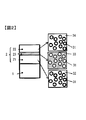
- FIG. 1 is a conceptual diagram showing a cross-sectional structure of a piston for an internal combustion engine according to an embodiment of the present invention.
- FIG. 2 is a conceptual diagram showing a cross-sectional structure of a piston for an internal combustion engine according to another embodiment of the present invention.
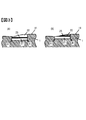
- FIG. 3 is a diagram showing a cross-sectional structure of a surface treatment unit according to an embodiment of the present invention.
- FIG. 3 (A) shows that all layers of the surface treatment unit have the same area, and FIG. The thing of which the area of each layer of a surface treatment part differs mutually is shown.
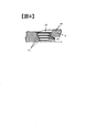
- FIG. 4 is a diagram showing a cross-sectional structure of the surface treatment unit according to the embodiment of the present invention.
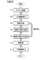
- FIG. 5 is a flowchart showing an example of a method for manufacturing a piston for an internal combustion engine according to an embodiment of the present invention.
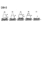
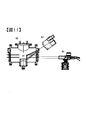
- FIG. 6 is a conceptual diagram illustrating a procedure for forming a surface treatment portion by friction stir welding in a method for manufacturing a piston for an internal combustion engine according to an embodiment of the present invention, and FIG. 6 (A) and FIG. 6 (C).
- FIG. 6B and FIG. 6D show the contact of the rotary tool, and FIG. 6E shows the formed surface treatment part.
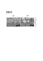
- FIG. 7 is an image obtained by photographing a cross section of the surface treatment portion formed as Example 1-2 with an optical microscope.
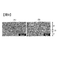
- FIG. 8 is an image obtained by photographing the lowermost layer cross section of the surface treatment portion formed as Example 1-2 with a scanning electron microscope, and FIG.
- FIG. 8B is surrounded by a broken line shown in FIG. It is the image which image
- FIG. 9 is an image obtained by photographing a cross section of the surface treatment portion formed as Example 1-2 with a scanning electron microscope, and FIG. 9B is surrounded by a broken line shown in FIG. 9A. An image of the area taken at a higher magnification
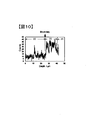
- FIG. 10 is a graph showing the results of oxygen analysis performed linearly in the depth direction from the surface of the surface treatment portion by energy dispersive X-ray spectroscopy with respect to the surface treatment portion formed as Example 1-2.
- FIG. 11 is a conceptual diagram showing a method for evaluating the heat insulation characteristics of the surface treatment portion.
- FIG. 10 is a graph showing the results of oxygen analysis performed linearly in the depth direction from the surface of the surface treatment portion by energy dispersive X-ray spectroscopy with respect to the surface treatment portion formed as Example 1-2.
- FIG. 11 is a conceptual diagram showing a method
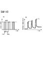
- FIG. 12 is a conceptual diagram showing the relationship between the laser light emission pattern and the surface temperature of the surface treatment portion in the evaluation of the heat insulation characteristics.
- FIG. 12A shows the laser light emitted from the laser light source toward the surface treatment portion.
- FIG. 12B shows the result of measuring the surface temperature of the surface treatment portion with an infrared camera.
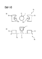
- FIG. 13 is a diagram for explaining the arrangement relationship between the joining tool used to form the surface treatment portion and the piston
- FIG. 13A is a plan view of the piston crown surface as viewed from above
- FIG. FIG. 13B is a side view of FIG.
- FIG. 14 is a table showing combinations of the material of the powder 51, the material of the powder 52, and the material of the rotary tool in Examples 1-1 to 1-8.
- FIG. 15 shows tensile tests on the materials of the powders 51 and 52 of Examples 1-9 to 1-17 and Comparative Examples 1-1 and 1-2, and the surface treatment part formed using these materials. It is a table
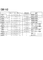
- FIG. 16 is a table showing peak temperatures T1 and T3 measured in the evaluation of heat insulation characteristics for the test pieces of Examples and Comparative Examples.
- FIG. 1 is a conceptual diagram showing a cross-sectional structure of a piston for an internal combustion engine according to an embodiment of the present invention.
- a surface treatment portion composed of a plurality of layers is formed on the crown surface of the piston for the internal combustion engine.
- the surface treatment portion is formed from the surface side in the depth direction in the first direction.
- a layer 23 made of a mixture of a metal layer or a first metal-containing layer 22 (hereinafter referred to as a first layer), a second metal containing oxygen or an oxide of the second metal, and a low thermal conductivity material. (Hereinafter referred to as a second layer) and a layer 21 (hereinafter referred to as a third layer) made of a mixture of a third metal and a low thermal conductivity material.
- An internal combustion engine piston is usually manufactured by processing a metal represented by an aluminum alloy.
- a metal represented by an aluminum alloy On the piston crown surface, in order to promote the combustion of fuel, it is desirable to sufficiently insulate the region involved in the combustion to prevent a temperature drop during the combustion.
- the coating layer is formed only on the piston crown surface with a low thermal conductivity material with high thermal insulation properties, the adhesiveness or bondability between the low thermal conductivity material and the piston base material is insufficient, and the joint strength at the interface between the two There is a problem that cannot be secured.
- the above problem can be solved by providing a surface treatment portion having the first layer, the second layer, and the third layer on the crown surface of the piston.
- the second layer is made of a material containing oxygen-containing metal or metal oxide and a low thermal conductivity material, thereby realizing low thermal conductivity and heat conduction in the thickness direction of the surface treatment portion. It has a function to suppress.
- the first layer on the surface of the surface treatment portion can be heated at a uniform temperature distribution because the lower second layer has a heat conduction suppressing function, which contributes to promoting fuel combustion.
- the third layer has a function of suppressing heat conduction to the base material while obtaining high joint strength with the piston base material.
- the metal used for the third layer is preferably aluminum, magnesium, iron, copper, zinc, titanium, nickel, or an alloy containing at least one of these metals. These metals are metals that can be solid-phase bonded to the metal material used for the piston base material, and it is easy to obtain high bonding strength to the piston base material.
- the piston base material is usually an aluminum alloy, and therefore the metal used for the third layer in contact with the piston base material is preferably aluminum or an aluminum alloy. This is because aluminum or an aluminum alloy can obtain a high bonding strength with respect to the aluminum alloy by a solid phase bonding method. Also, the metal used for the first layer is preferably aluminum or an aluminum alloy. Thereby, the first layer and the third layer can be bonded to the piston base material of the aluminum alloy with a high bonding strength by the solid phase bonding method, and a uniform heating state can be easily obtained on the surface layer of the surface treatment portion.
- FIG. 2 is a conceptual diagram showing a cross-sectional structure of a piston for an internal combustion engine according to another embodiment of the present invention.
- the surface treatment part which consists of a several layer is comprised also in the crown surface of this piston for internal combustion engines.
- the first layer is a layer made of a mixture of a metal and a low thermal conductivity material. With such a configuration, the heat insulation characteristics of the surface treatment portion can be further improved.
- the metal contained in the second layer as an oxygen-containing state or oxide state is preferably the same as the metal contained in the third layer.
- the piston for an internal combustion engine according to the embodiment of the present invention may have a shape having a concave portion on the crown surface, and the surface treatment portion may be provided with a structure filling the concave surface.
- FIG. 3 is a diagram showing a cross-sectional structure of the surface treatment portion formed on the concave surface provided on the piston crown surface 11 described above.
- FIG. 3A shows a case where all of the plurality of layers constituting the surface treatment portion are formed in the same area.
- FIG. 3B shows a case where a part of the first layer and the second layer are missing from a plurality of parts constituting the surface treatment unit. That is, the area of each layer of the surface treatment portion is different from each other.
- a piston for an internal combustion engine having good fuel efficiency and excellent durability is provided. In the configuration shown in FIG.
- the first layer and the second layer are not formed in the entire surface treatment portion, but the second layer is 50% or more of the surface area of the surface treatment portion. If formed in this way, it is possible to provide a piston for an internal combustion engine having good fuel efficiency and excellent durability.
- connection portion where the side surface and the bottom surface are in contact with each other in the concave portion formed in the piston crown surface 11 to form the surface treatment portion.
- the molding material can be satisfactorily solid-phase bonded over the entire recess. If this portion is not a curved surface, the molding material remains in the connection portion in a state where the solid material is not bonded to the solid phase, which causes a defective solid phase bonding.
- the thickness of the second layer is larger in the peripheral portion than in the central portion. In the periphery of the piston, heat conduction to the side surface of the piston occurs. By making the thickness of the second layer thicker at the peripheral portion than at the central portion, heat conduction to the piston side surface can be suppressed and the heat insulating effect can be enhanced. Moreover, it is preferable to have a structure which has a stirring part in the outer peripheral part of a surface treatment part.
- the agitation part refers to the part where the material composition flowed.
- the outer peripheral portion of the surface treatment portion tends to be difficult to ensure the bonding strength, but the bonding strength can be ensured by providing a region in which the piston base material and the surface treatment portion material are agitated.
- the area of the surface treatment part is preferably smaller on the lower side (lower side) than on the piston crown side (upper side).
- FIG. 4 shows a cross-sectional structure of the surface treatment portion provided so that the second layer and the third layer are alternately repeated three times under the first layer.
- the area of each layer is larger as the layer is formed in the upper part.
- the advantages of such a configuration are as follows.
- the heat insulation effect is preferably higher at the upper part of the surface treatment part.
- blocked can be ensured by making the area of the layer of the lower part of a surface treatment part small.
- the position where the surface treatment portion is formed is not particularly limited, but is preferably the piston crown surface in the vicinity of the region where the fuel is injected. Since the liquid fuel is vaporized and combusted in the region where the fuel is injected, the combustion promoting effect can be enhanced by forming the surface treatment portion at this position.
- low thermal conductivity material zirconia, cordierite, mullite, silicon, silica, mica, talc, silicate glass, acrylic glass, organic glass, silica airgel, hollow ceramic beads, hollow glass beads, It is preferable to use any one or a combination of hollow metal spheres, organosilicon compounds, and ceramic fibers.
- the volume ratio of the low thermal conductivity material contained is preferably 45% or more.
- the volume ratio of the low thermal conductivity material is 45% or more, high heat insulation characteristics can be obtained, so that it is possible to raise the temperature of the piston crown surface in a shorter time, and thus a high combustion promoting effect can be expected.
- FIG. 5 is a flowchart showing an example of a method for manufacturing a piston for an internal combustion engine according to an embodiment of the present invention.
- the piston is cast.
- the casting of the piston is performed by casting a rough material of the piston made of an aluminum alloy by a known method such as a die casting method.
- primary machining is performed, and predetermined machining including outer diameter cutting of the land portion and pin hole machining is performed on the rough material of the piston.
- the concave portion for forming the surface treatment portion on the piston crown surface may be formed by casting at the time of piston casting in step S1, or may be formed by machining at the time of primary machining in step S2. .
- step S3 the material for forming the surface treatment portion is filled in the recess formed on the piston crown surface.
- the material may be filled in a powder state, or a molded body (briquette) obtained by applying pressure to the powder and solidified may be prepared and filled with the molded body.
- step S4 the rotary tool is rotated for a predetermined time while the rotary tool is in contact with the material filled in the recess.
- step S5 the rotary tool is pulled out from the recess.
- Friction-Stir-Welding (FSW) is performed by a series of steps from Step S3 to Step S5. Steps S3 to S5 are repeated as many times as necessary depending on the number of layers. Details of the friction stir welding will be described later.
- step S6 the piston on which the surface treatment portion is formed is taken out and subjected to heat treatment.
- the purpose of this heat treatment is to remove the strain generated by the plastic flow of the material during friction stir welding and to make the strength of the surface treatment portion uniform.
- Examples of the heat treatment include solution aging treatment and artificial aging treatment.
- secondary machining is performed in step S7. As the secondary machining, finishing machining is performed, and the product piston is completed.
- Steps S3 to S5 will be described in detail.
- step S3 first, a material for forming the third layer of the surface treatment portion is filled in the concave portion of the piston crown surface.
- step S4 After rotating the rotary tool as described above in step S4, the rotary tool is pulled out from the recess in step S5. Thereby, the third layer is formed. At this time, the surface layer of the third layer becomes the second layer.
- the process returns to step S3, and the material for forming the first layer is filled on the second layer. Subsequently, after rotating the rotary tool in step S4, the rotary tool is pulled out from the recess in step S5. Thereby, the first layer is formed on the second layer.
- the details of the formation process of the second layer will be described later.
- the steps S3 to S5 are repeated as necessary depending on the configuration of the surface treatment portion to be formed.
- the third layer is formed by repeating the steps S3 to S5 as many times as the number of repetitions. To do.
- the third layer and the second layer are alternately repeated.
- the first layer is formed on the last formed second layer in steps S3 to S5.
- FIG. 6 is a conceptual diagram showing an example of the procedure of friction stir welding for forming the surface treatment portion on the piston crown surface.
- FIG. 6A shows a state in which the first material filling (powder 51 filling) is performed in the concave portion formed on the piston crown surface. That is, a state in which a material (powder or a compact of powder) for forming the third layer is filled in the recess is shown.
- FIG. 6 (B) shows a state in which the rotary tool 4 is inserted into the recess and is rotated while being in contact with the filled material.
- the material for forming the third layer is softened by frictional heat and is friction stir welded to the bottom and sides of the recess. That is, the first friction stir welding is performed.
- the second layer is also formed at the same time.
- FIG. 6C shows a state where the second material filling (powder 52 filling) is performed. That is, it shows a state in which a material for forming the first layer (powder or a compact of powder) is filled on the second layer formed in the recess.
- FIG. 6D shows a state in which the rotary tool 4 is inserted into the recess and is rotated in a state where it is in contact with the filled material.
- the material for forming the first layer is softened by frictional heat and is friction stir welded to the already formed second layer and the side of the recess. That is, the second friction stir welding is performed.
- FIG. 6E shows a state in which the surface treatment portion is formed in the concave portion of the piston crown surface by a series of steps.
- Friction stir welding is one of the solid-phase joining techniques for joining metals.
- a rotating tool is rotated while pressed against a metal material to be joined, and heated by the generated frictional heat, thereby causing a composition flow in the metal material (ie, stirring), and metal Join materials.
- the surface treatment portion according to the present invention is preferably formed by friction stir welding.
- friction stir welding can join metal materials in an environment containing oxygen as in the atmosphere with almost no adverse effect on the bonding strength due to the oxidation of the material.
- Friction stir welding is not only a metal material, but a material containing metal can be joined without causing poor bonding due to the oxidation of the material at the joint location.
- the surface layer portion of the third layer is a layer made of a mixture of oxygen-containing metal or metal oxide and a low thermal conductivity material. That is, the second layer can be formed simultaneously. Thereafter, the first layer can be formed by the second friction stir welding.
- a region containing a large amount of oxygen may be generated in the surface layer portion of the first layer of the surface treatment portion.
- a region When such a region is generated, it can be removed by cutting shown as a secondary machining process.
- it is possible to suppress the production
- a mixed powder containing a metal and a low thermal conductivity material or a molded body thereof is used. Thereby, as shown in FIG.1 and FIG.2, it is possible to form the 3rd layer in which the low thermal conductivity material was disperse
- a fusion welding method such as arc welding
- the melting point and specific gravity differ between the metal and the low thermal conductivity material, so that these materials are separated. is there.
- the volume ratio of the low thermal conductivity material in the mixed powder is preferably 80% or less. When the volume ratio exceeds 80%, the bonding strength is insufficient, and the surface treatment part once formed may be peeled off.
- Example 1 A test piece that looks like a piston crown is prepared, and a surface treatment portion is formed on the surface.
- a disk-shaped test piece was prepared from the same aluminum alloy (4032-T6) as the material of the piston base material, and a recess having a diameter of 30 mm and a depth of 5 mm was formed on the upper surface thereof.
- the powder 51 was pushed into the concave portion of the test piece by applying a load while rotating a rotary tool having a diameter of 30 mm at 800 rpm. After holding the rotary tool for a predetermined time so that the lower end of the rotary tool was positioned at a height of 1.5 mm from the bottom surface of the recess, the rotary tool was pulled out from the recess.
- a predetermined amount of powder 52 was filled in the recess, and a load was applied while rotating a rotating tool having a diameter of 34 mm at 800 rpm. Thereby, the powder 52 was pushed in with the rotary tool while crushing around the concave portion of the test piece.
- the rotary tool was held for a predetermined time so that the tip of the rotary tool was positioned at a height of 3.0 mm from the bottom surface of the recess, and then the rotary tool was pulled up to complete the friction stir welding.
- a surface treatment portion having a thickness of about 3.0 mm was formed in the concave portion of the test piece.
- the surface layer of the surface treatment part was removed by 0.1 mm by lathe processing, and the upper surface of the disk-shaped test piece was flattened.
- flash of the test piece base material was formed in the circumference
- the materials of the powder 51 and the powder 52 described above were variously changed to form a plurality of types of surface treatment portions in the recesses of the test pieces, and Examples 1-1 to 1-8 were used.
- the materials of the powder 51 and the powder 52 and the material of the rotary tool are as shown in FIG.
- the powder 51 is a powder material filled in the first material filling step
- the powder 52 is a powder material filled in the second material filling step.
- the metal powder a powder produced by an atomizing method was used.
- Al is pure aluminum powder having an average particle size of 30 ⁇ m
- Mg is pure magnesium powder having an average particle size of 30 ⁇ m
- Cu is pure copper powder having an average particle size of 30 ⁇ m
- Zn is pure zinc powder having an average particle size of 50 ⁇ m
- Fe is an average.
- Ti represents pure titanium powder with an average particle size of 30 ⁇ m
- Ni represents pure nickel powder with an average particle size of 30 ⁇ m.
- ZrO 2 represents yttria-stabilized zirconia powder formed into a spherical shape having an average particle diameter of 30 ⁇ m.
- the numerical value of the percentage shown in FIG. 14 represents the volume ratio of the low thermal conductivity material shown in the entire powder material.
- Rotating tool used in the friction stir welding method is preferably selected according to the type of metal material contained in the materials to be joined.
- the metal material is Al or Zn having a relatively low melting point
- a rotary tool made of the tool steel SKD61 can be used.
- a rotary tool made of a cemented carbide made of a WC-Co alloy (a mixed sintered material of tungsten carbide and cobalt) is used. It is preferable to use it. Moreover, it is preferable to use a rotary tool made of silicon nitride for the metal material having a high melting point of Fe, Ti, or Ni.
- FIG. 7 is an image obtained by photographing the cross section of the surface treatment portion of Example 1-2 with an optical microscope.
- the left side is the side close to the side surface of the piston
- the right side is the side close to the central portion of the piston.
- the third layer 21 and the first layer 22 are formed as the surface treatment portion
- the second layer 23 is formed between these layers.
- zirconia as the low thermal conductivity material 31 is uniformly dispersed in the third layer and the first layer.
- the thickness of the second layer 23 is thicker on the left side near the piston central part than on the right side on the piston central part side. This is because when friction stir welding is performed, the outer peripheral speed of the rotary tool is higher than that of the inner side of the rotary tool, so that more frictional heat is generated and the temperature tends to be higher, and the amount of oxygen taken up is larger.
- the second layer is formed thicker.
- FIG. 8 and 9 are images obtained by photographing the cross section of the surface treatment portion of Example 1-2 shown in FIG. 7 with a scanning electron microscope.
- FIG. 8 is an enlarged photograph of the interface between the piston base material 1 and the third layer 21 that is the lowermost layer of the surface treatment portion, and FIG. 8B is surrounded by a broken line shown in FIG. It is the image which image
- FIG. 9 is an enlarged photograph of the first layer, the second layer, and the third layer with the second layer 23 interposed therebetween.
- FIG. 9B is an enlarged image of a region surrounded by a broken line shown in FIG.
- the aluminum alloy which is the material of the piston base material 1
- the third layer of aluminum which is the lowermost layer of the surface treatment portion, are completely bonded, and the interface between them is unclear. That is, it can be seen that the metal material of the surface treatment portion has a structure integrated with the piston base material.
- the metal powder contained in the powder 51 as the first filling material is aluminum, so that the layer formed is formed on the piston base material made of an aluminum alloy. On the other hand, it is joined with high adhesion strength.
- the metal powder contained in the powder 51 is a metal other than aluminum, as long as it is a material that forms an alloy with aluminum or forms an intermetallic compound, the layer to be formed is against the piston base material made of aluminum alloy. With sufficient adhesion strength.
- magnesium, copper, iron, zinc, titanium, nickel, etc. can be used.
- the second layer is formed between the third layer formed by the first friction stir welding and the first layer formed by the second friction stir welding. Can be confirmed.
- FIG. 10 is a graph showing the results of oxygen analysis performed linearly in the depth direction from the surface of the surface treatment portion by energy dispersive X-ray spectroscopy with respect to the surface treatment portion formed as Example 1-2. It can be seen that the oxygen concentration is high in a region deeper than about 26 ⁇ m from the surface of the surface treatment portion. This region corresponds to the second layer, and it can be seen that the second layer contains a large amount of oxygen.
- the first layer and the second layer, the second layer and the third layer Higher adhesion can be obtained at the interface between the layers.
- a second layer containing oxygen is formed between the first layer and the third layer, but if the metal materials contained in the first layer and the third layer are the same, the similarity in crystal structure Thus, it is possible to obtain a more firmly bonded state.
- a tensile adhesion test defined in JIS-H8402 was conducted.
- a cylindrical part having a diameter of 25 mm is cut out from the test piece including the surface treatment part formed on the surface thereof.
- Two cylindrical jigs with a diameter of 25 mm are prepared. Each of the two jigs is bonded to the upper and lower surfaces of the test piece on which the surface treatment portion is formed with an epoxy adhesive.
- the powders 51 and 52 had a zirconia content rate of 85% by volume and a comparative example 1-1 in which a surface treatment portion was formed using a mixed powder of aluminum and zirconia, and the silica content rate. Evaluation was also performed on Comparative Example 1-2 in which the surface treatment portion was formed using a mixed powder of aluminum and silica at a volume ratio of 85%.
- Tensile test results for powders 51 and 52 used in the production of Examples 1-9 to 1-17 and Comparative Examples 1-1 and 1-2, and the surface-treated parts formed using these materials Is shown in FIG.
- FIG. 15 shows the evaluation results of the adhesion strength of the surface treatment parts of Examples 1-9 to 1-17 and Comparative Examples 1-1 and 1-2 (Example 1-2 is also included for reference). Displayed).
- Example 1-2 is also included for reference.
- FIG. 15 shows the evaluation results of the adhesion strength of the surface treatment parts of Examples 1-9 to 1-17 and Comparative Examples 1-1 and 1-2 (Example 1-2 is also included for reference). Displayed).
- the low thermal conductivity material is contained in a volume ratio of up to 80%, a predetermined adhesion strength can be obtained.
- the surface treatment part was not fixed by friction stir welding, and the powder dropped off.
- the epoxy adhesive part was broken and the adhesion strength was 80 MPa or more.
- the content ratio of the low thermal conductivity material is 70% by volume
- Example 1-12 in which the low thermal conductivity material is zirconia, fracture occurs inside the surface treatment portion (layer interface), and the low thermal conductivity material becomes In Example 1-16 of silica, the surface-treated portion broke at the interface with the test piece base material.
- the adhesion strengths of these examples were 70 MPa and 65 MPa, respectively.
- the content ratio of the low thermal conductivity material was 75% by volume ratio (Example 1-13: the low thermal conductivity material was zirconia), the adhesion strength was 60 MPa or more.
- the surface treatment part was broken at the interface with the test piece base material.
- the adhesion strength was 18 MPa.
- the adhesion strength was 21 MPa. That is, both showed a predetermined adhesion strength.
- the big adhesive strength is acquired when the content rate of a low heat conductivity material is 75% by volume ratio, it is more preferable.
- Example 2 The heat insulation property in the surface treatment part was evaluated.
- a specific evaluation method will be described with reference to FIG.
- FIG. 11 is a conceptual diagram showing an evaluation method.
- FIG. 12 is a conceptual diagram showing the relationship between the laser light emission pattern and the surface temperature of the surface treatment section.
- FIG. 12A shows an emission pattern of laser light emitted from the laser light source 64 toward the surface treatment unit
- FIG. 12B shows the temporal change in the surface temperature of the surface treatment unit at that time as infrared rays.
- the result measured by the camera 63 is shown.
- the peak temperature measured at the first laser irradiation was T1
- the peak temperature measured at the third laser irradiation was T3.
- FIG. 16 shows the measured peak temperatures T1 and T3 for the test pieces of Examples and Comparative Examples.
- Examples 2-1 to 2-8 are obtained by forming a surface treatment portion on a test piece by friction stir welding. A black body paint is applied to the surfaces of all the test pieces.
- Comparative Example 2-1 is a test piece not subjected to surface treatment.
- Comparative Example 2-2 one layer of Al-55% ZrO 2 having a thickness of 2.9 mm was formed without using friction stir welding.
- Comparative Example 2-3 a 20 ⁇ m thick alumina layer was provided on the surface of the test piece by anodization.
- Comparative Example 2-4 a zirconia layer having a thickness of 1.5 mm was provided on the surface of the test piece by plasma spraying. Note that the same aluminum alloy (4032-T6) as that of the piston base material was used for all the test piece materials according to the examples and comparative examples.
- the peak temperature when the laser beam was irradiated to the test piece of Comparative Example 2-1 was about 200 ° C. in order to simulate the environment inside the combustion chamber of the internal combustion engine.
- the laser light emission conditions of the laser light source 64 were set as follows. Specifically, as shown in FIG. 12A, a set of irradiation patterns of irradiating laser light having an intensity of 800 W for 1 second and then stopping the irradiation for 5 seconds is set as one set, and a total of three sets of irradiation are performed in Comparative Example 2. -1 test piece.
- the surface temperature of the test piece rises while the laser beam is irradiated, but decreases due to natural heat dissipation when the laser beam irradiation is stopped.
- FIG. 12B shows the time course of such a temperature change.
- the laser light source 64 is irradiated with laser light to a plurality of test pieces, the temperature change thereof is measured, and the surface temperature can be set to 300 ° C. or more, and the temperature rising effect is excellent. .
- the test piece of Comparative Example 2-2 is not sufficient although T3 rises to 285 ° C., although some heat insulation effect is recognized. This is presumably because the layer corresponding to the second layer is not formed. Further, the test piece of Comparative Example 2-3 does not have a sufficient heat insulating effect. That is, the heat insulating effect of the alumina layer is not sufficient.
- T3 is 300 ° C. or higher and a sufficient heat insulating effect is exhibited. That is, it can be seen that a sufficient heat insulating effect is exhibited by the surface treatment portion according to the embodiment of the present invention.
- the peak temperature T1 of the first laser irradiation is 300 ° C. or more, and a more excellent heat insulating effect is recognized. This is presumably because the first layer on the surface layer side also contains a low thermal conductivity material having a volume ratio of 50% or more.
- the test piece of Comparative Example 2-4 shows very high temperatures of T1 of 510 ° C. and T3 of 650 ° C.
- the zirconia layer formed by plasma spraying has poor adhesion at the interface with the test piece base material.
- the heat insulation effect is too high, the temperature rise becomes excessively local. For this reason, even if a zirconia coating is formed on the piston crown by plasma spraying, the durability is poor and a good combustion state cannot be obtained, so that practical use is difficult.
- Example 2-1 to Example 2-8 when the surface treatment portion shown in Example 2-1 to Example 2-8 is applied to the piston crown surface, it has a heat shielding effect in the depth direction of the surface treatment portion and is applied to the surface of the piston crown surface. Therefore, it is possible to uniformly heat an appropriate range to obtain an appropriate temperature distribution, and a sufficient combustion promoting effect can be obtained in a wide range.
- Example 3 A procedure for forming the surface treatment portion on the piston crown surface will be described. As described in step S1 along the flowchart shown in FIG. 5, the piston was cast, and an aluminum alloy (AC8A) was used as the base material of the piston. Next, as explained in step S2, primary machining was performed on the rough piston material. Next, as described in steps S3 to S5, a series of steps of material filling, friction stir welding, and drawing of the rotary tool was repeated twice to form a surface treatment portion. Next, after performing heat treatment as step S6, it was processed into a finished shape by secondary machining as step S7, and a predetermined piston was produced. The recess filled with the powder was formed by processing into a hole shape having a diameter of 30 mm and a depth of 5 mm during primary machining.
- AC8A aluminum alloy
- FIG. 13 is a diagram for explaining the arrangement relationship between the joining tool 70 and the piston used when the surface treatment portion is formed by friction stir welding on the piston rough material.
- FIG. 13 (A) is a plan view of the piston crown surface as viewed from above, and
- FIG. 13 (B) is a side view of FIG. 13 (A).
- the joining tool 70 is disposed on the upper surface of the base 73, the center jig 71 for supporting the piston 1, and a pair of movably attached to the upper surface of the base 73 to fix the piston 1 from the side surface.
- the side jig 72 is used.
- a convex portion is formed on the upper surface of the center jig 71.
- a cylindrical surface having the same radius as the side surface of the piston 1 is formed on the side surface of each of the pair of side jigs 72 on the center jig 71 side, and a convex portion 72a is formed on the cylindrical surface.
- the piston 1 When forming the surface treatment portion on the crown surface of the piston 1 by friction stir welding, the piston 1 is fixed as follows. First, the concave portion on the lower surface of the piston 1 is fitted into the convex portion of the center jig 71 to hold the piston 1 on the center jig 1. Next, the pair of side jigs 72 are respectively moved toward the piston 1, the pair of convex portions 72 a are inserted into the holes in the side surfaces of the piston 1, and the side surfaces of the piston 1 are formed by the cylindrical surfaces of the pair of side jigs 72. Press to fix from both sides. Thereby, the piston 1 is positioned and fixed at the position where the rotary tool rotates during the friction stir welding.
- Example 4 A procedure for forming the surface treatment portion having the configuration shown in FIG. 4 will be described.
- the surface treatment portion shown in FIG. 4 is formed by alternately repeating the third layer and the second layer three times in this order on the surface of the recess formed on the piston crown surface, and the first layer as the uppermost layer. Is provided.
- the piston 1 having the surface treatment portion having such a configuration formed on the crown surface was produced according to the flowchart shown in FIG. First, the coarse material of the piston 1 was cast, and then the primary material was subjected to primary machining. The concave portion of the piston crown surface for forming the surface treatment portion was formed by primary machining so as to have a diameter of 28 mm and a depth of 7.5 mm.
- a third friction stir welding was performed using a rotating tool having a diameter of 34 mm, and the third layer and the second layer were formed so as to be alternately repeated three times in this order.
- friction stir welding was performed in the same manner while rotating a rotary tool having a diameter of 36 mm to form the first layer as the uppermost layer. Thereafter, heat treatment secondary machining was performed to produce the piston 1.
- the first layer is formed on the concave portion of the crown surface of the piston for forming the surface treatment portion, in which the third layer and the second layer are alternately and repeatedly formed three times in this order, A surface treatment portion having a total of 7 layers was formed.
- the areas of the plurality of third layers and second layers have larger diameters at the top, and the area of the first layer is the largest.
- a surface treatment portion having a total thickness of 4 mm was formed by four times friction stir welding.
- the diameter of the rotary tool is larger than the diameter of the recess, but the diameter of the recess and the diameter of the rotary tool may be the same.
- the diameter of the rotary tool used for friction stir welding is 30 mm for the first friction stir welding, 32 mm for the second friction stir welding, 34 mm for the third friction stir welding, and for the fourth friction stir welding. It was 36 mm. Powder 51 was used as a molding material for the first to third friction stir welding, and powder 52 was used as a molding material for the fourth friction stir welding.
- the layer formed by one friction stir welding was 1.0 mm, and the total thickness of the entire surface treatment portion was 4.0 mm.
- the outermost layer containing oxygen formed on the upper part of the first layer formed by the fourth friction stir welding was cut out by secondary machine machining.
- the piston 1 as shown in FIG. 4 was created by the above procedure.
- the piston 1 includes three layers each including a third layer and a second layer, and the second layer as the uppermost layer.
- the surface area of each layer is larger as the upper layer is formed.
- the molding material remains in this portion in a state where the solid material is not solid-phase bonded, and causes the solid-phase bonding failure portion.
- the reason for this is that heat is likely to escape from the connecting portion, and a gap is formed between the rotating tool and the friction stir welding, so that it is difficult to apply a sufficient load to the molding material of this portion. .
- the present invention it is possible to provide a piston for an internal combustion engine that has excellent heat insulation characteristics and suppresses deposit and smoke emission and has good fuel efficiency. Moreover, since the surface treatment portion and the piston base material are firmly joined, it is possible to provide a piston for an internal combustion engine having excellent durability.
Landscapes
- Chemical & Material Sciences (AREA)
- Engineering & Computer Science (AREA)
- Mechanical Engineering (AREA)
- Chemical Kinetics & Catalysis (AREA)
- Inorganic Chemistry (AREA)
- Materials Engineering (AREA)
- Metallurgy (AREA)
- Organic Chemistry (AREA)
- General Engineering & Computer Science (AREA)
- Combustion & Propulsion (AREA)
- Other Surface Treatments For Metallic Materials (AREA)
- Pistons, Piston Rings, And Cylinders (AREA)
- Pressure Welding/Diffusion-Bonding (AREA)
Abstract
内燃機関用ピストンは、ピストン冠面のピストン母材に、表面側から深さ方向に向かって、第1の金属の層または第1の金属を含有する層による第1層、酸素を含有する第2の金属または第2の金属の酸化物と、低熱伝導率材料とを含有する第2層、および、第3の金属と低熱伝導率材料との混合物による第3層、を有する表面処理部を設けた。
Description
本発明は内燃機関用ピストンと内燃機関用ピストンの製造方法に関する。
従来、内燃機関用ピストンの冠面上の一部であって、燃料が液体で衝突する燃料衝突部を含み且つ主たる燃焼領域を含む領域が、低熱伝導率かつ低比熱の部材または構造体により構成されているものが知られている。このピストンの構成によれば、燃料衝突部での昇温効果を高めてピストンに衝突する燃料の燃焼を促進し、ピストン冠面への燃料の付着を減少させデポジットやスモークの排出を抑制することができるとされている(特許文献1)。
しかしながら、特許文献1に開示された内燃機関用のピストンにおいては、低熱伝導率の部材の具体的な構成方法に関して記載されていない。また、低熱伝導率部材とピストン母材との間に発生する温度分布により、低熱伝導率部材とピストン母材との界面における接合あるいは接着強度が十分でないという問題がある。
本発明の第1の態様によれば、内燃機関用ピストンは、ピストン冠面のピストン母材に、表面側から深さ方向に向かって、第1の金属の層または前記第1の金属を含む層による第1層、酸素を含有した第2の金属または前記第2の金属の酸化物と、低熱伝導率材料とを含む第2層、および、第3の金属と前記低熱伝導率材料との混合物による第3層を有する表面処理部が設けられている。
本発明の第2の態様によれば、内燃機関用ピストンの製造方法は、冠面に表面処理部を備えた内燃機関用ピストンの製造方法において、前記表面処理部の形成工程は、前記ピストンのピストン母材の冠面に凹部を形成する凹部形成工程と、前記凹部に粉末または粉末の成形体である第1成形材料を充填する第1充填工程と、前記第1成形材料に回転工具を当接させて前記第1成形体材料を摩擦熱により軟化させ前記凹部に前記第1成形材料を固相接合し、かつ、前記第1成形材料と前記ピストン母材との撹拌部を形成する第1撹拌接合工程と、前記第1撹拌接合工程により固相接合されて形成された形成層の上に、粉末または粉末の成形体である第2成形材料を充填する第2充填工程と、前記第2成形材料に回転工具を当接させて前記第2成形材料を摩擦熱により軟化させ前記凹部に前記第2成形材料を固相接合し、かつ、前記第2成形材料と前記ピストン母材との撹拌部を形成する第2撹拌接合工程と、を少なくとも有する。
本発明の第2の態様によれば、内燃機関用ピストンの製造方法は、冠面に表面処理部を備えた内燃機関用ピストンの製造方法において、前記表面処理部の形成工程は、前記ピストンのピストン母材の冠面に凹部を形成する凹部形成工程と、前記凹部に粉末または粉末の成形体である第1成形材料を充填する第1充填工程と、前記第1成形材料に回転工具を当接させて前記第1成形体材料を摩擦熱により軟化させ前記凹部に前記第1成形材料を固相接合し、かつ、前記第1成形材料と前記ピストン母材との撹拌部を形成する第1撹拌接合工程と、前記第1撹拌接合工程により固相接合されて形成された形成層の上に、粉末または粉末の成形体である第2成形材料を充填する第2充填工程と、前記第2成形材料に回転工具を当接させて前記第2成形材料を摩擦熱により軟化させ前記凹部に前記第2成形材料を固相接合し、かつ、前記第2成形材料と前記ピストン母材との撹拌部を形成する第2撹拌接合工程と、を少なくとも有する。
本発明によれば、上述の構成の表面処理部を有することで優れた断熱特性によりデポジットやスモークの排出が抑制され燃費が良好な内燃機関用ピストンを提供できる。また、表面処理部とピストン母材とは強固に接合されるため、耐久性に優れた内燃機関用ピストンを提供できる。
以下、本発明の実施の形態について、図面を参照して説明する。図1は、本発明の一実施の形態に係る内燃機関用ピストンの断面構造を示す概念図である。図1に示す通り、この内燃機関用ピストンの冠面には、複数の層からなる表面処理部が構成されている、この表面処理部は、表面側から深さ方向に向かって、第1の金属の層または第1の金属を含む層22(以下、第1層と呼ぶ)、酸素を含有した第2の金属または第2の金属の酸化物と、低熱伝導率材料との混合物による層23(以下、第2層と呼ぶ)、および、第3の金属と低熱伝導率材料との混合物による層21(以下、第3層と呼ぶ)を有する。
内燃機関用ピストンは、通常、アルムニウム合金に代表される金属を加工して製造される。ピストン冠面においては、燃料の燃焼を促進するために、燃焼に関与する領域を十分に断熱して燃焼時の温度低下を防止することが望まれる。しかし、ピストン冠面に、断熱特性が高い低熱伝導率材料のみで被覆層を形成した場合、低熱伝導率材料とピストン母材との接着性あるいは接合性が不足して、両者の界面の接合強度を確保できないという課題がある。
また、ピストン冠面近傍における燃料の燃焼を促進するためには、燃焼に関与する領域を均一に高温化する必要がある。しかし、ピストン冠面に、断熱特性の高い低熱伝導率材料のみで被覆層を形成した場合、被覆層表面には局所的に高温となる領域が発生する傾向があるという問題がある。
この点に関して、ピストン冠面に金属と低熱伝導率材料との複合材による単層を形成した場合、形成された層とピストン母材との間で十分な接合強度が得られ、かつ、燃焼により発生した熱はピストン母材内を伝導して、ピストン冠面を均一に加熱できる。しかし、ピストン母材内の熱伝導は高く、その結果、断熱特性が不足してピストン冠面を十分高い温度に保てないという問題がある。
そこで、図1に示すように、第1層、第2層および第3層を有する表面処理部をピストン冠面に設けることで、上記の問題を解決できる。第2層は、酸素を含む金属または金属の酸化物と、低熱伝導率材料と、を含む材料により構成することで、低い熱伝導率を実現し、表面処理部の厚さ方向への熱伝導を抑制する機能を有する。また、表面処理部の表面の第1層は、その下部の第2層が熱伝導抑制機能を有するために均一な温度分布で高温化することができ、燃料の燃焼を促進することに寄与する。さらに、第3層は、ピストン母材との高い接合強度を得ると同時に、母材への熱伝導を抑制する機能を有する。
第3層に用いる金属としては、アルミニウム、マグネシウム、鉄、銅、亜鉛、チタン、ニッケルのいずれか1種類、またはこれらの金属のうちの少なくとも1種類を含む合金であることが好ましい。これらの金属は、ピストン母材に使用される金属材料と固相接合が可能な金属であり、ピストン母材への高い接合強度を得やすい。
上記の通り、ピストン母材は通常はアルミニウム合金であり、従って、ピストン母材に接する第3層に用いる金属としては、アルミニウムまたはアルミニウム合金であることが好ましい。アルミニウムあるいはアルミニウム合金は、固相接合法によりアルミニウム合金に対して高い接合強度を得ることができるからである。また、第1層に用いる金属としても、アルミニウムまたはアルミニウム合金であることが好ましい。これにより、第1層および第3層は、アルミニウム合金のピストン母材に対して固相接合法により高い接着強度で接合でき、かつ、表面処理部の表層で均一な加熱状態も得やすくなる。
図2は、本発明の別の実施形態に係る内燃機関用ピストンの断面構造を示す概念図である。図2に示す通り、この内燃機関用ピストンの冠面にも、複数の層からなる表面処理部が構成されている。本実施の形態においては、第1層は、金属と低熱伝導率材料との混合物による層である。このような構成により、表面処理部の断熱特性をさらに向上させることができる。
第2層の、酸素を含有した状態または酸化物の状態として含まれる金属は、第3層に含まれる金属と同一であることが好ましい。本発明の実施形態に係る内燃機関用ピストンは、冠面に凹部を有した形状とし、この凹面を埋める構造で表面処理部を設けることも可能である。
図3は、上記説明のピストン冠面11に設けた凹面に形成された表面処理部の断面構造を示す図である。図3(A)は、表面処理部を構成する複数の層の全てが同じ面積に形成されている場合を示している。また、図3(B)は、表面処理部を構成する複数のうち、第1層および第2層の一部が欠けている場合を示している。すなわち、表面処理部の各層の面積は互いに異なる。図3(A)、図3(B)いずれの場合にも、燃費が良好で耐久性に優れた内燃機関用ピストンが提供される。なお、図3(B)に示す構成では、上記の通り、第1層および第2層は表面処理部の領域全体に形成されていないが、第2層が表面処理部の表面積の50%以上に形成されていれば、燃費が良好で耐久性に優れた内燃機関用ピストンを提供することができる。
上記各実施の形態の内燃機関用ピストンにおいては、表面処理部を形成するためにピストン冠面11に形成する凹部において、側面と底面とが接する接続部分は、曲面により構成されることが好ましい。このような曲面を構成することにより、凹部全域で成形材料を良好に固相接合することができる。この部分が曲面でない場合、成形材料が固相接着されない状態で接続部分に残り、固相接合不良の部分を生じる原因となる。
第2層は、中央部における厚さに比べて周辺部における厚さが大きいことが好ましい。ピストンの周辺部ではピストン側面への熱伝導が発生する。第2層の厚さを中央部に比べて周辺部で厚くすることで、ピストン側面への熱伝導を抑制し断熱効果を高めることができる。また、表面処理部の外周部には撹拌部を有する構造を有することが好ましい。撹拌部とは材料が組成流動した部分を指す。表面処理部の外周部は、接合強度を確保しにくい傾向があるが、ピストン母材の材料と表面処理部の材料とを撹拌させた領域を設けることで接合強度を確保することができる。
第2層は一層であっても十分な断熱効果が得られるが、第2層を複数有する構成とすることにより、さらに高い断熱効果が期待でき好ましい。表面処理部の面積は、ピストン冠面側(上部側)に比べて、下部側(下部側)が小さいことが好ましい。
図4は、第1層の下に第2層と第3層とが交互に3回繰り返すように設けた表面処理部の断面構造を示す。図4に示す通り、各層の面積は、上部に構成された層ほど大きい。このような構成とする利点は次の通りである。断熱効果は表面処理部の上部ほど高いことが好ましいが、反面、表面処理部の下部では、表面処理部の上部で遮断されずに伝わった熱を逃がす必要がある。この点について、表面処理部の下部の層の面積を小さくすることにより、遮断されずに伝わった熱の移動経路を確保することができる。
表面処理部が形成される位置は特に限定されないが、燃料が噴射される領域近傍のピストン冠面であることが好ましい。燃料が噴射される領域では液体燃料が気化して燃焼するので、この位置に表面処理部を形成することにより、燃焼促進効果を高めることができる。
低熱伝導率材料については特に限定されないが、ジルコニア、コージェライト、ムライト、シリコン、シリカ、雲母、タルク、ケイ酸塩ガラス、アクリルガラス、有機ガラス、シリカエアロゲル、中空のセラミックビーズ、中空のガラスビーズ、中空の金属球、有機珪素化合物、セラミック繊維のいずれか1種または複数種を組み合わせて用いることが好ましい。
第2層および第3層において、含有する低熱伝導率材料の体積比率は45%以上であることが好ましい。低熱伝導率材料の体積比率が45%以上の場合には、高い断熱特性が得られるため、ピストン冠面をより短時間で温度上昇させることが可能であり、これにより高い燃焼促進効果が期待できる。
図5は、本発明の一実施形態に係る内燃機関用ピストンの製造方法の一例を示すフローチャートである。ステップS1ではピストンの鋳造を行う。ピストンの鋳造は、ダイキャスト法等の公知の方法により、アルミニウム合金製のピストンの粗材を鋳造する。続く、ステップS2では、一次機械加工を行い、ピストンの粗材に対して、ランド部の外径切削やピン穴加工等を含む所定の機械加工を施す。ピストン冠面に表面処理部を形成するための凹部は、ステップS1におけるピストン鋳造の際に鋳抜きにより形成してもよく、あるいはステップS2における一次機械加工の際に機械加工により形成してもよい。
ステップS3では、表面処理部を形成するための材料をピストン冠面に形成された凹部に充填する。この場合、材料は粉末の状態で充填してもよいし、あるいは、粉末に圧力を加えて固めた成形体(ブリケット)を作製し、この成形体を充填してもよい。
次に、ステップS4では、凹部に充填された材料に回転工具を当接させた状態で所定の時間だけ回転させる。次に、ステップS5では、回転工具を凹部から引き抜く。ステップS3からステップS5の一連の工程により、摩擦撹拌接合(FSW:Friction-Stir-Welding)が行われる。ステップS3からステップS5の工程は、必要に層数に応じた回数だけ繰り返す。摩擦撹拌接合に関しては詳細を後述する。
ステップS6では、表面処理部が形成されたピストンを取り出し熱処理を施す。この熱処理は摩擦撹拌接合の際に材料が塑性流動したことに伴って発生した歪を除去し、表面処理部の強度を均一化することを目的とするものである。熱処理としては、例えば、溶体化時効処理や人工時効処理がある。ステップS6において熱処理を行った後、ステップS7で二次機械加工を施す。二次機械加工として、仕上げの切削加工を施し、製品としてのピストンが完成する。
ステップS3~S5について詳しく説明する。ステップS3においては、まず、表面処理部のうちの第3層を形成するための材料をピストン冠面の凹部に充填する。次に、ステップS4で上記の通り回転工具を回転させた後、ステップS5で回転工具を凹部から引き抜く。これにより第3層が形成される。この時、第3層の表層は第2層となる。次に、ステップS3に戻り、第1層を形成するための材料を第2層の上に充填する。続いて、ステップS4で回転工具を回転させた後、ステップS5で回転工具を凹部から引き抜く。これにより、第2層の上に第1層が形成される。なお、第2層の形成過程については詳細を後述する。
上記の通り、ステップS3~S5の工程は、形成しようとする表面処理部の構成により必要に応じて繰り返す。例えば、図4に示されたような、第3層と第2層が交互に繰り返される構成の場合、その繰り返し数に応じた回数だけ、ステップS3~S5の工程を繰り返して第3層を形成する。これにより、第3層と第2層が交互に繰り返される構成となる。必要な繰り返し数の第3層と第2層が形成された後、ステップS3~S5により、最後に形成された第2層の上に第1層を形成する。
図6は、ピストン冠面に表面処理部を形成するための、摩擦撹拌接合の手順の一例を示す概念図である。図6(A)は、ピストン冠面に形成された凹部に1回目の材料充填(粉末51の充填)が行われた状態を示す。すなわち、凹部に第3層を形成するための材料(粉末または粉末の成形体)が充填された状態を示す。
図6(B)は、凹部に回転工具4を挿入し充填された材料に当接させた状態で回転させている状態を示す。これにより、第3層を形成するための材料は摩擦熱により軟化して凹部の底部および側部に摩擦撹拌接合される。すなわち、1回目の摩擦撹拌接合が行われる。この時、上記の通り、第2層も同時に形成される。
図6(C)は、2回目の材料充填(粉末52の充填)が行われた状態を示す。すなわち、凹部に形成された第2層の上に第1層を形成するための材料(粉末または粉末の成形体)が充填された状態を示す。図6(D)は、凹部に回転工具4を挿入し充填された材料に当接させた状態で回転させている状態を示す。これにより、第1層を形成するための材料は摩擦熱により軟化して既に形成されている第2層および凹部側部に摩擦撹拌接合される。すなわち、2回目の摩擦撹拌接合が行われる。図6(E)は、一連の工程により、ピストン冠面の凹部に表面処理部が形成された状態を示す。
次に、摩擦攪拌接合について説明する。摩擦攪拌接合は金属と金属とを接合する固相接合手法の一つである。摩擦攪拌接合を行うには、回転工具を接合しようとする金属材料に押し当てた状態で回転させ、発生した摩擦熱により加熱することで、金属材料に組成流動を起こし(すなわち攪拌する)、金属材料を接合する。
金属材料を接合するための別の方法として、アーク溶接などの溶融溶接法もある。しかし、溶融溶接法では、金属材料が溶融した後に凝固するという工程を経るため、接合部に凝固に伴う組織が形成され、強度特性などの劣化の原因となる。これに対して、摩擦撹拌接合では、材料の溶融(融解)・凝固が起きないため、上記のような強度問題が発生せず、材料をより強固に接合することが可能である。本発明に係る表面処理部は摩擦撹拌接合により形成することが好ましい。
また、摩擦撹拌接合は、大気中のように酸素を含む環境において、材料が酸化されることによる接合強度への悪影響をほとんど受けることなく金属材料を接合することが可能である。摩擦撹拌接合は、金属材料のみならず、金属を含む材料であれば、接合箇所に材料の酸化に伴う結合不良が発生することなく接合できる。
摩擦撹拌接合においては、接合しようとする材料に回転工具を当接させて回転させる際、回転工具が当接している材料の表面においては、材料に含まれる金属に酸素が結びつきやすい状態となる。このため、接合された層の表層部は、酸素を含有した金属あるいは金属の酸化物が含まれる別の組成の層となる。
すなわち、1回目の摩擦撹拌接合工程により第3層を形成する際、第3層の表層部は、酸素を含有する金属あるいは金属の酸化物と、低熱伝導率材料との混合物による層となる。すなわち、第2層を同時に形成することができる。その後、2回目の摩擦撹拌接合により、第1層を形成することができる。
従って、表面処理部の第1層の表層部にも酸素を多く含む領域が生成されることがある。このような領域が生成された場合には、二次機械加工工程として示される切削加工により除去することが可能である。なお、最表面の層(第1層)の摩擦撹拌接合工程を、アルゴンガス中や真空中などの酸素を含まない雰囲気で実施することにより、酸素を含む領域の生成を抑制することが可能である。
1回目の材料充填工程においては、金属と低熱伝導率材料とを含む混合粉末またはその成形体を使用する。これにより、図1や図2に示すように、低熱伝導率材料を分散させた第3層を形成することが可能である。
アーク溶接などの溶融溶接法では、混合粉末やその成形体を用いて表面処理部を形成しようすると、金属と低熱伝導率材料とで融点や比重が異なるため、これらの材料が分離するという問題がある。この点についても、表面処理部を、機械的な撹拌作用のある摩擦撹拌接合により形成することにより、層全体にわたって金属と低熱伝導率材料とが均一に分散した層を形成することが可能である。
金属粉末と低熱伝導率材料粉末とを混合した材料を用いて摩擦撹拌接合を行う場合、金属粉末のみがピストン母材と接合することにより、形成された層はピストン母材に固定される。すなわち、低熱伝導率材料とピストン母材とは直接的に接合されない。このため、低熱伝導率材料の含有比率を決定する際には、接合強度に留意する必要がある。本発明者らの研究によれば、混合粉末中の低熱伝導率材料の体積比率は80%以下とすることが好ましい。体積比率が80%を超えた場合は接合強度が不足して、一旦形成した表面処理部が剥離するおそれがある。
(実施例1)
ピストン冠面に見立てた試験片を作製し、その表面に表面処理部を形成する。ピストン母材の材料と同様のアルミニウム合金(4032-T6)から円盤状の試験片を作製し、その上面に直径30mm、深さ5mmの凹部を形成した。凹部に粉末51を所定量だけ凹部に充填した後、直径30mmの回転工具を800rpmで回転させながら荷重をかけて粉末51を試験片の凹部に押込んだ。回転工具の下端が凹部の底面から1.5mmの高さの位置となるように回転工具を所定時間保持した後、回転工具を凹部から引き抜いた。
ピストン冠面に見立てた試験片を作製し、その表面に表面処理部を形成する。ピストン母材の材料と同様のアルミニウム合金(4032-T6)から円盤状の試験片を作製し、その上面に直径30mm、深さ5mmの凹部を形成した。凹部に粉末51を所定量だけ凹部に充填した後、直径30mmの回転工具を800rpmで回転させながら荷重をかけて粉末51を試験片の凹部に押込んだ。回転工具の下端が凹部の底面から1.5mmの高さの位置となるように回転工具を所定時間保持した後、回転工具を凹部から引き抜いた。
次に、粉末52を所定量だけ凹部に充填し、直径34mmの回転工具を800rpmで回転させながら荷重をかけた。これにより、試験片の凹部周辺を押し潰しながら粉末52を回転工具で押込んだ。回転工具を、その先端が凹部の底面から3.0mmの高さの位置となるように所定時間保持した後、回転工具を引き上げて摩擦撹拌接合を終了した。
上記手順により、試験片の凹部には、厚さ約3.0mmの表面処理部が形成された。次に、表面処理部の表層を旋盤加工により0.1mm除去し、円盤状試験片の上面を平坦化した。なお、凹部の周囲には、回転工具を押し込んで加工したことにより、試験片母材のバリが形成されたが、旋盤加工によりバリは取り除いた。
上記の粉末51および粉末52の材料を種々変更して試験片の凹部に複数種類の表面処理部を形成し、実施例1-1~実施例1-8とした。実施例1-1~実施例1-8における、粉末51および粉末52の材料と回転工具の材料は、図14に示す通りである。なお、粉末51とは1回目の材料充填工程により充填した粉末材料であり、粉末52とは2回目の材料充填工程により充填した粉末材料である。
金属粉末としてはアトマイズ法により作製された粉末を用いた。図14において、Alは平均粒径30μmの純アルミニウム粉末、Mgは平均粒径30μmの純マグネシウム粉末、Cuは平均粒径30μmの純銅粉末、Znは平均粒径50μmの純亜鉛粉末、Feは平均粒径50μmの純鉄粉末、Tiは平均粒径30μmの純チタン粉末、およびでNiは平均粒径30μmの純ニッケル粉末を表す。また、低熱伝導率材料としては、ZrO2は、平均粒径30μmの球形に成形したイットリア安定化ジルコニアの粉末を表す。なお、図14に示された百分率の数値は、粉末材料全体に示す低熱伝導率材料の体積比率を表している。
摩擦撹拌接合法に用いる回転工具は、接合しようとする材料に含まれる金属材料の種類により、その材料を選択することが好ましい。金属材料が、融点の比較的低いAlやZnの場合には、工具鋼SKD61を材料とする回転工具を用いることが可能である。
金属材料が、反応性の高いMgや融点が中程度のCuの場合には、WC-Co合金(タングステン・カーバイドとコバルトとの混合焼結材)からなる超硬合金を材料とする回転工具を用いることが好ましい。また、金属材料が、融点の高いFe、Ti、Niに対しては、窒化珪素を材料とする回転工具を用いることが好ましい。
図7は、実施例1-2の表面処理部の断面を光学顕微鏡により撮影した像である。図7において、左側はピストンの側面に近い側であり、右側はピストンの中央部に近い側である。表面処理部として第3層21と第1層22が形成され、これらの層の間には第2層23が形成されているのがわかる。また、第3層および第1層において、低熱伝導率材料31としてのジルコニアが均一に分散していることがわかる。
また、図7からわかるように、第2層23の厚さに関して、ピストン中央部に近い左側では、ピストン中央部側の右側に比べて厚い。これは、摩擦撹拌接合を行う際、回転工具の外側では内側に比べて周速度が大きいために、より多くの摩擦熱が発生して高温になりやすく、また、酸素の取り込み量も多いために、第2層がより厚く形成される。
図8および図9は、図7に示した実施例1-2の表面処理部の断面を走査型電子顕微鏡により撮影した像である。図8は、ピストン母材1と表面処理部の最下層である第3層21の界面を拡大撮影したものであり、図8(B)は、図8(A)に示された破線で囲まれた領域をより高倍率で撮影した像である。また、図9は、第2層23を挟んで第1層、第2層および第3層を拡大撮影したものである。図9(B)は、図9(A)に示された破線で囲まれた領域を拡大した像である。
図8からわかるように、ピストン母材1の材料であるアルミニウム合金と、表面処理部の最下層である第3層のアルミニウムとは完全に結合され、両者の界面は不明瞭である。すなわち、表面処理部の金属材料はピストン母材に一体化された構造となっていることがわかる。
実施例1-1および実施例1-2のように、1回目の充填材料としての粉末51が含有する金属粉末をアルミニウムとすることで、形成される層は、アルミニウム合金製のピストン母材に対して高い密着強度で接合される。しかし、粉末51が含有する金属粉末がアルミニウム以外の金属であっても、アルミニウムと合金化あるいは金属間化合物を形成する材料であれば、形成される層は、アルミニウム合金製のピストン母材に対して十分な密着強度で接合される。実施例1-3~実施例1-8のように、例えば、マグネシウム、銅、鉄、亜鉛、チタン、ニッケルなどは使用可能である。
また、図9からわかるように、1回目の摩擦撹拌接合により形成された第3層と2回目の摩擦撹拌接合により形成された第1層との間には第2層が形成されていることが確認できる。
図10は、実施例1-2として形成した表面処理部に対して、エネルギー分散型X線分光法により表面処理部表面から深さ方向に直線状に酸素分析した結果を示すグラフである。表面処理部の表面から約26μmより深い領域で酸素濃度が高いことが分かる。この領域は第2層に対応しており、第2層には酸素が多く含まることがわかる。
また、1回目の摩擦撹拌接合に用いる粉末51と2回目の摩擦撹拌接合に用いる粉末52とで、含有する金属材料が同種である場合、第1層と第2層、第2層と第3層の間の界面において、より高い密着性を得ることができる。第1層と第3層との間には、酸素を含む第2層が形成されるが、第1層と第3層とに含まれる金属材料が同種であれば、結晶構造の類似性から、より強固に結合した状態を得ることができる。
表面処理部の密着強度を確認するため、JIS-H8402に規定される引張密着性試験を実施した。試験片から、その表面に形成した表面処理部を含んで直径25mmの円柱状の部分を切り出す。直径25mmの円柱状治具を2個用意する。表面処理部が形成されている試験片上面と下面のそれぞれに、上記2個の治具のそれぞれをエポキシ系接着剤により接着する。
引張試験機により2個の円柱状治具を引張り、表面処理部に対して垂直の方向に引張り応力を発生させ、表面処理膜が破断するかまたは試験片母材から剥離する際の応力を測定した。この応力を表面処理部の密着強度として評価した。なお、エポキシ系接着剤の破断強度は80MPaであるため、表面処理部の密着強度が80MPa以上である場合は、エポキシ系接着剤部分が破断する。このような場合には、表面処理部の真の密着強度は測定されないので、密着強度80MPa以上とした。実施例1-1~実施例1-8について評価したところ、いずれの場合もエポキシ樹脂部が破断した。すなわち、密着強度は80MPa以上であった。
次に、粉末51および52において、低熱伝導率材料の種類とその含有率を変えたものを用いて摩擦撹拌接合により試験片に表面処理部を形成し、実施例1-9~実施例1-17とした。これらの試験片についても、実施例1-1~実施例1-8についての上記説明と同様の手順により密着強度を評価した。なお、各実施例における粉末51と52とは同じ材料を用いた。
また、比較例として、粉末51および52が、ジルコニアの含有率を体積比率で85%としてアルミニウムとジルコニアの混合粉末を用いて表面処理部を形成した比較例1-1と、シリカの含有率を体積比率で85%としてアルミニウムとシリカの混合粉末を用いて表面処理部を形成した比較例1-2についても評価を行った。実施例1-9~実施例1-17、および比較例1-1、1-2の作製に用いた粉末51および52と、これらの材料を用いて形成された表面処理部に対する引張試験の結果については図15に示す。
図15に、実施例1-9~実施例1-17、および比較例1-1、1-2の表面処理部の密着強度の評価結果を示す(参考のために実施例1-2も併せて表示した)。図15からわかるように、低熱伝導率材料は体積比率で80%まで含有させても、所定の密着強度が得られることがわかる。しかし、低熱伝導率材料を体積比率で85%含有させた場合は、摩擦撹拌接合により表面処理部が固定せず、粉末が脱落することがわかった。
低熱伝導率材料の含有率が体積比率で60%以下の場合には、エポキシ系接着剤の部分が破断し、密着強度は80MPa以上であった。低熱伝導率材料の含有率が体積比率で70%の場合には、低熱伝導率材料がジルコニアの実施例1-12では、表面処理部の内部(層界面)で破断し、低熱伝導率材料がシリカの実施例1-16では、表面処理部は試験片母材との界面で破断した。これらの実施例の密着強度はそれぞれ、70MPaと65MPaであった。低熱伝導率材料の含有率が体積比率で75%の場合(実施例1-13:低熱伝導率材料はジルコニア)、密着強度は60MPa以上であった。
低熱伝導率材料の含有率が体積比率で80%の場合には、表面処理部は試験片母材との界面で破断した。低熱伝導率材料がジルコニアの実施例1-14では、密着強度は18MPaであった。また、低熱伝導率材料がシリカの実施例1-17では、密着強度は21MPaであった。すなわち、共に所定の密着強度を示した。なお、低熱伝導率材料の含有率は体積比率で75%までの場合には大きな密着強度が得られるので、より好ましい。
(実施例2)
表面処理部における断熱特性を評価した。具体的な評価方法について図11を参照して説明する。図11は評価方法を示す概念図である。真空チャンバ62の内部に表面処理部を形成した実施例および比較例の試験片61を配置し、レーザー光源64からレーザー光を出射させ、試験片61の表面諸部に照射する。この状態で、赤外線カメラ63により試験片の表面温度の変化を測定する。
表面処理部における断熱特性を評価した。具体的な評価方法について図11を参照して説明する。図11は評価方法を示す概念図である。真空チャンバ62の内部に表面処理部を形成した実施例および比較例の試験片61を配置し、レーザー光源64からレーザー光を出射させ、試験片61の表面諸部に照射する。この状態で、赤外線カメラ63により試験片の表面温度の変化を測定する。
図12は、レーザー光の出射パターンと表面処理部の表面温度との関係を示す概念図である。図12(A)は、レーザー光源64から表面処理部に向けて出射させたレーザー光の出射パターンを示し、図12(B)は、その際の表面処理部の表面温度の時間的変化を赤外線カメラ63により測定した結果を示す。1回目のレーザー照射時に測定されたピーク温度をT1、3回目のレーザー照射時に測定されたピーク温度をT3とした。
実施例および比較例の試験片について、測定されたピーク温度T1およびT3を図16の表に示す。図16において、実施例2-1~実施例2-8は、摩擦撹拌接合により試験片に表面処理部を形成したものである。なお、全ての試験片の表面には黒体塗料が塗布されている。
比較例2-1は表面処理を施していない試験片である。比較例2-2は、摩擦撹拌接合によらずに厚さ2.9mmのAl-55%ZrO2による層を1層形成したものである。比較例2-3は、試験片表面に陽極酸化により厚さ20μmのアルミナ層を設けたものである。比較例2-4は、試験片表面にプラズマ溶射により厚さ1.5mmのジルコニア層を設けたものである。なお、実施例および比較例による試験片の材料は全て、ピストン母材と同様のアルミニウム合金(4032-T6)を用いた。
断熱特性の評価には内燃機関における燃焼反応を考慮する必要がある。以下、この点について説明する。内燃機関における燃焼反応を促進する上で、ピストン冠面の表面温度を上昇させることが重要である。例えば、軽油および重油の自然発火点は250℃~350℃であり、ガソリンを点火する際の温度は300℃程度である。よって、これらの燃料の燃焼を促進するためには、ピストン冠面の表面温度を300℃付近まで昇温させる必要がある。
本実施例の断熱特性の評価においては、内燃機関の燃焼室内部の環境を模擬的に実現するために、比較例2-1の試験片にレーザー光を照射した際のピーク温度が約200℃となるようなレーザー光源64のレーザー光の出射条件を設定した。具体的には、図12(A)に示すように、強度800Wのレーザー光を1秒間照射した後、5秒間照射を停止するという照射パターンを1セットとし、合計3セットの照射を比較例2-1の試験片に対して行った。
試験片の表面温度は、レーザー光が照射されている間は上昇するが、レーザー光の照射が停止されると自然放熱により低下する。図12(B)は、このような温度変化の時間経過を示している。
レーザー光源64から上記のようにレーザー光を複数の試験片に照射して、その温度変化を測定し、表面温度を300℃以上とすることができるものを、昇温効果が優れたものとする。
図16からわかる通り、比較例2-2の試験片は、T3が285℃まで上昇することから、ある程度の断熱効果は認められるものの十分ではない。これは第2層に相当する層が形成されていないことが原因と考えられる。また、比較例2-3の試験片では十分な断熱効果がない。すなわち、アルミナ層の断熱効果は十分でない。
これに対して、実施例2-1~実施例2-8の試験片ではいずれもT3が300℃以上であり、十分な断熱効果を示すことがわかる。すなわち、本発明の実施の形態に係る表面処理部により十分な断熱効果が発揮されていることがわかる。
特に、実施例2-3~実施例2-8の試験片においては、レーザー照射1回目のピーク温度T1が300℃以上であり、より優れた断熱効果が認められる。これは、表層側の第1層にも体積比率で50%以上の低熱伝導率材料を含有させているためと考えられる。
なお、比較例2-4の試験片はT1が510℃、T3が650℃と非常に高い温度を示している。ただし、プラズマ溶射により形成したジルコニア層は、試験片母材との界面における密着性が悪い。また、断熱効果があまりに高い場合、温度上昇が過剰に局所的となる。このため、ピストン冠面にプラズマ溶射によりジルコニア被膜を形成しても、耐久性が悪く、また、良好な燃焼状態を得られないため、実用は困難である。
一方、実施例2-1~実施例2-8に示す表面処理部をピストン冠面に施した場合、表面処理部の深さ方向に対して遮熱効果を有するとともに、ピストン冠面の表面に沿って適度な熱伝導が得られるため、適切な範囲を均一に加熱して適切な温度分布とすることが可能であり、広い範囲で十分な燃焼促進の効果が得られる。
(実施例3)
ピストン冠面に表面処理部を形成する手順について説明する。図5に示したフローチャートに沿って、ステップS1として説明した通り、ピストンの鋳造を行った、ピストンの母材としてはアルミニウム合金(AC8A)を材料に用いた。次に、ステップS2として説明した通り、ピストンの粗材に対して一次機械加工を施した。次に、ステップS3~S5として説明した通り、材料充填、摩擦撹拌接合、および回転工具の引抜きの一連の工程を2回繰り返し、表面処理部を形成した。次に、ステップS6として熱処理を施した後、ステップS7として二次機械加工により仕上げ形状に加工し、所定のピストンを作製した。なお、粉末を充填する凹部は一次機械加工時に直径30mmで深さ5mmの穴状に加工することにより形成した。
ピストン冠面に表面処理部を形成する手順について説明する。図5に示したフローチャートに沿って、ステップS1として説明した通り、ピストンの鋳造を行った、ピストンの母材としてはアルミニウム合金(AC8A)を材料に用いた。次に、ステップS2として説明した通り、ピストンの粗材に対して一次機械加工を施した。次に、ステップS3~S5として説明した通り、材料充填、摩擦撹拌接合、および回転工具の引抜きの一連の工程を2回繰り返し、表面処理部を形成した。次に、ステップS6として熱処理を施した後、ステップS7として二次機械加工により仕上げ形状に加工し、所定のピストンを作製した。なお、粉末を充填する凹部は一次機械加工時に直径30mmで深さ5mmの穴状に加工することにより形成した。
図13はピストンの粗材に対して摩擦撹拌接合により表面処理部を形成する際に使用した接合用工具70とピストンの配置関係を説明する図である。図13(A)は、ピストン冠面を上方から見た平面図、図13(B)は図13(A)の側面図である。
接合用工具70は、ベース73、ベース73の上面に配置されてピストン1を支持するためのセンタ治具71と、ベース73の上面に移動可能に取り付けられてピストン1を側面から固定する一対のサイド治具72等により構成される。センタ治具71の上面には凸部が形成されている。また、一対のサイド治具72のそれぞれのセンタ治具71側の側面は、ピストン1の側面と同一半径の円筒面が形成されており、この円筒面には凸部72aが形成されている。
ピストン1の冠面に摩擦撹拌接合により表面処理部を形成する際には、ピストン1を次のように固定する。まず、ピストン1の下面の凹部をセンタ冶具71の凸部に嵌合させて、ピストン1をセンタ治具1に保持する。次に、一対のサイド治具72をそれぞれピストン1の方に移動させ、一対の凸部72aをピストン1の側面の穴部に挿入し、一対のサイド冶具72の円筒面にてピストン1の側面を両側から加圧して固定する。これにより、摩擦撹拌接合の際に回転工具が回転する位置に、ピストン1を位置決めして固定する。
(実施例4)
図4に示した構成の表面処理部を形成する手順について説明する。図4に示した表面処理部は、ピストン冠面に形成された凹部の表面に、第3層と第2層をこの順序で交互に3回繰り返して形成された上に最上層として第1層が設けられた構成である。
図4に示した構成の表面処理部を形成する手順について説明する。図4に示した表面処理部は、ピストン冠面に形成された凹部の表面に、第3層と第2層をこの順序で交互に3回繰り返して形成された上に最上層として第1層が設けられた構成である。
このような構成の表面処理部が冠面に形成されたピストン1は、図5に示されたフローチャートに従って作製した。まず、ピストン1の粗材を鋳造し、次に、このピストン粗材に一次機械加工を施した。表面処理部を形成するためのピストン冠面の凹部は一次機械加工により、直径28mm、深さ7.5mmとなるように形成した。
次に、凹部に粉末51を充填した後、直径30mmの回転工具を回転させながら荷重をかけた。これにより、凹部の周辺を押し潰しながら粉末51を回転工具により押し込んで1回目の摩擦撹拌接合を行い、第3層と第2層とをこの順序で形成した。次に、形成された第2層の上に粉末51を充填した後、直径32mmの回転工具を回転させながら荷重をかけた。これにより、既に形成されている第3層と第2層との上に、2回目の摩擦撹拌接合により、さらに第3層と第2層がこの順序で形成した。同様にして、直径34mmの回転工具を用いて3回目の摩擦撹拌接合を行い、第3層と第2層がこの順序で交互に3回繰り返すように形成した。次に、粉末52を最も上部の第2層の上に充填した後、直径36mmの回転工具を回転させながら同様に摩擦撹拌接合を行い、最上層として第1層を形成した。その後、熱処理二次機械加工を施し、ピストン1を作製した。
上記の工程により、表面処理部を形成するためのピストン冠面の凹部には、第3層と第2層がこの順序で交互に3回繰り返して形成された上に第1層が形成され、合計7層の構成による表面処理部が形成された。複数の第3層および第2層の面積は、上部ほど直径が大きく、第1層の面積は最も大きい。1回の摩擦撹拌接合により1mmの厚さの層を形成することで、4回の摩擦撹拌接合により合計4mmの厚さ表面処理部を形成した。なお、上記の各摩擦撹拌接合においては、凹部の径に比べて回転工具の径は大きいが、凹部の径と回転工具の径は同じであってもよい。
摩擦撹拌接合に用いた回転工具の直径は、1回目の摩擦撹拌接合用として30mm、2回目の摩擦撹拌接合用として32mm、3回目の摩擦撹拌接合用として34mm、4回目の摩擦撹拌接合用として36mmであった。1回目から3回目までの摩擦撹拌接合には成形材料として粉末51を用い、4回目の摩擦撹拌接合には成形材料として粉末52を用いた。
1回の摩擦撹拌接合で形成される層は1.0mmとし、表面処理部全体としての合計厚さを4.0mmとした。4回目の摩擦撹拌接合により形成された第1層の上部に形成された酸素を含む最表層は、二次機機械加工により切除した。
以上の手順により、図4に示すようなピストン1を作成した。このピストン1は、第3層と第2層をそれぞれ3層ずつ、最上層として第2層を備え、各層の表面積は上層ほど大きい。
なお、上記で、表面処理部を形成する凹部の側面と底面とが接する接続部分が曲面でない場合、成形材料が固相接着されない状態でこの部分に残り、固相接合不良の部分を生じる原因となる旨説明した。この理由として、上記接続部分では、熱が逃げやすく、また摩擦撹拌接合の際に回転工具との間の隙間が生じ、この部分の成形材料に対して十分な荷重が付加されにくいことが考えられる。
この問題を解決するために、センタ冶具71の凸分とピストン下部の凹部と寸法精度を高めて嵌合状態を改善する方法も考えられるが、このような解決方法に比べて、上記接続部分を曲面とする方法はより簡便である。
以上説明した通り、本発明によれば、優れた断熱特性によりデポジットやスモークの排出が抑制され燃費が良好な内燃機関用ピストンを提供できる。また、表面処理部とピストン母材とは強固に接合されるため、耐久性に優れた内燃機関用ピストンを提供できる。
なお、本発明は、以上説明した実施の形態に限定されない。本発明の要旨を変更しない範囲で、具体的な構成材料、部品などを変更してもよい。また、本発明の構成要素を含んでいれば、公知の技術を追加し、あるいは公知の技術で置き換えることも可能である。
次の優先権基礎出願の開示内容は引用文としてここに組み込まれる。
日本国特許出願2015年第233208号(2015年11月30日出願)
日本国特許出願2015年第233208号(2015年11月30日出願)
1 ピストン母材
2 表面処理部
4 回転工具
11 ピストン冠面
21 第3層
22 第1層
23 第2層
31 低熱伝導率材料
32 金属
33 酸素を含有した金属または金属の酸化物
34 金属
51、52 粉末
61 試験片
62 真空チャンバ
63 赤外線カメラ
64 レーザー光源
70 接合用工具
71 センタ冶具
72 サイド冶具
73 ベース
2 表面処理部
4 回転工具
11 ピストン冠面
21 第3層
22 第1層
23 第2層
31 低熱伝導率材料
32 金属
33 酸素を含有した金属または金属の酸化物
34 金属
51、52 粉末
61 試験片
62 真空チャンバ
63 赤外線カメラ
64 レーザー光源
70 接合用工具
71 センタ冶具
72 サイド冶具
73 ベース
Claims (14)
- ピストン冠面のピストン母材に、表面側から深さ方向に向かって、第1の金属の層または前記第1の金属を含有する層による第1層、酸素を含有する第2の金属または前記第2の金属の酸化物と、低熱伝導率材料とを含有する第2層、および、第3の金属と前記低熱伝導率材料との混合物による第3層、を有する表面処理部を設けた、内燃機関用ピストン。
- 請求項1に記載の内燃機関用ピストンであって、
前記第3の金属は、アルミニウム、マグネシウム、鉄、銅、亜鉛、チタン、ニッケルのいずれか1種類、またはこれらの金属のうちの少なくとも1種類を含有する合金である、内燃機関用ピストン。 - 請求項1または請求項2に記載の内燃機関用ピストンであって、
前記第1の金属と前記第3の金属とは、共に、アルミニウムまたはアルミニウム合金である、内燃機関用ピストン。 - 請求項1に記載の内燃機関用ピストンであって、
前記第1層は、前記第1の金属に加えて前記低熱伝導率材料を含有する、内燃機関用ピストン。 - 請求項1に記載の内燃機関用ピストンであって、
前記第2層は、中央部における厚さに比べて周辺部における厚さが大きい、内燃機関用ピストン。 - 請求項1に記載の内燃機関用ピストンであって、
前記第2の金属と、前記第3の金属とは同一である、内燃機関用ピストン。 - 請求項1に記載の内燃機関用ピストンであって、
前記第1の金属と、前記第2の金属とは同一である、内燃機関用ピストン。 - 請求項1に記載の内燃機関用ピストンであって、
前記第3層において、前記第2層に接する面に対向する面と外周面とが接する部分は曲面により構成されている、内燃機関用ピストン。 - 請求項1に記載の内燃機関用ピストンであって、
前記表面処理部の外周部と、前記ピストン母材との間には、前記表面処理部を構成する材料と前記ピストン母材を構成する材料との撹拌部を有する、内燃機関用ピストン。 - 請求項1に記載の内燃機関用ピストンであって、
前記第2層を複数有する、内燃機関用ピストン。 - 請求項1に記載の内燃機関用ピストンであって、
前記第3層の面積は、前記第1層の面積よりも小さい、内燃機関用ピストン。 - 請求項1に記載の内燃機関用ピストンであって、
前記第2層および前記第3層において、前記低熱伝導率材料の体積比率は50%以上である内燃機関用ピストン。 - 請求項1に記載の内燃機関用ピストンであって、
前記低熱伝導率材料は、ジルコニア、コージェライト、ムライト、シリコン、シリカ、雲母、タルク、ケイ酸塩ガラス、アクリルガラス、有機ガラス、シリカエアロゲル、中空のセラミックビーズ、中空のガラスビーズ、中空の金属球、有機珪素化合物、セラミック繊維、チタン合金、低合金鋼、鋳鉄、のうち少なくともいずれか一つを含有する材料である、内燃機関用ピストン。 - 冠面に表面処理部を備えた内燃機関用のピストンの製造方法であって、
前記表面処理部の形成工程は、
前記ピストンのピストン母材の冠面に凹部を形成する凹部形成工程と、
前記凹部に粉末または粉末の成形体である第1成形材料を充填する第1充填工程と、
前記第1成形材料に回転工具を当接させて前記第1成形材料を摩擦熱により軟化させ前記凹部に前記第1成形材料を固相接合し、かつ、前記第1成形材料と前記ピストン母材との撹拌部を形成する第1撹拌接合工程と、
前記第1撹拌接合工程により固相接合されて形成された形成層の上に、粉末または粉末の成形体である第2成形材料を充填する第2充填工程と、
前記第2成形材料に回転工具を当接させて前記第2成形材料を摩擦熱により軟化させ前記凹部に前記第2成形材料を固相接合し、かつ、前記第2成形材料と前記ピストン母材との撹拌部を形成する第2撹拌接合工程と、を少なくとも有する、内燃機関用ピストンの製造方法。
Priority Applications (2)
| Application Number | Priority Date | Filing Date | Title |
|---|---|---|---|
| CN201680066954.XA CN108291311B (zh) | 2015-11-30 | 2016-11-29 | 内燃机用活塞以及内燃机用活塞的制造方法 |
| US15/779,810 US20180369954A1 (en) | 2015-11-30 | 2016-11-29 | Piston for internal combustion engine and method of manufacturing piston for internal combustion engine |
Applications Claiming Priority (2)
| Application Number | Priority Date | Filing Date | Title |
|---|---|---|---|
| JP2015-233208 | 2015-11-30 | ||
| JP2015233208A JP6557583B2 (ja) | 2015-11-30 | 2015-11-30 | 内燃機関用ピストンおよび内燃機関用ピストンの製造方法 |
Publications (1)
| Publication Number | Publication Date |
|---|---|
| WO2017094728A1 true WO2017094728A1 (ja) | 2017-06-08 |
Family
ID=58796862
Family Applications (1)
| Application Number | Title | Priority Date | Filing Date |
|---|---|---|---|
| PCT/JP2016/085433 Ceased WO2017094728A1 (ja) | 2015-11-30 | 2016-11-29 | 内燃機関用ピストンおよび内燃機関用ピストンの製造方法 |
Country Status (4)
| Country | Link |
|---|---|
| US (1) | US20180369954A1 (ja) |
| JP (1) | JP6557583B2 (ja) |
| CN (1) | CN108291311B (ja) |
| WO (1) | WO2017094728A1 (ja) |
Families Citing this family (4)
| Publication number | Priority date | Publication date | Assignee | Title |
|---|---|---|---|---|
| TWI682822B (zh) * | 2018-07-16 | 2020-01-21 | 國立中正大學 | 摩擦攪拌積層製造方法 |
| JP2020133492A (ja) * | 2019-02-20 | 2020-08-31 | 日立オートモティブシステムズ株式会社 | 内燃機関のピストンおよびその製造方法 |
| JP2020186722A (ja) * | 2019-05-10 | 2020-11-19 | マツダ株式会社 | エンジンのピストン及びその製造方法 |
| AU2022246294B2 (en) | 2021-03-22 | 2026-03-12 | Commonwealth Scientific And Industrial Research Organisation | Method for forming a metal matrix composite structure |
Citations (6)
| Publication number | Priority date | Publication date | Assignee | Title |
|---|---|---|---|---|
| JPS6176745A (ja) * | 1984-09-20 | 1986-04-19 | Mitsubishi Heavy Ind Ltd | セラミツクス組込型ピストン |
| JPS6159854U (ja) * | 1984-09-26 | 1986-04-22 | ||
| JPH03151545A (ja) * | 1989-10-31 | 1991-06-27 | Inco Ltd | ピストン‐シリンダ組立体 |
| JPH08501602A (ja) * | 1992-09-30 | 1996-02-20 | ユナイテッド テクノロジーズ コーポレイション | 複合セラミックコーティング材 |
| JP2014025418A (ja) * | 2012-07-27 | 2014-02-06 | Hitachi Automotive Systems Ltd | 内燃機関のピストン及びこのピストンの製造方法 |
| WO2015016122A1 (ja) * | 2013-08-01 | 2015-02-05 | 日立オートモティブシステムズ株式会社 | 内燃機関用ピストンの製造方法および内燃機関用ピストン |
Family Cites Families (6)
| Publication number | Priority date | Publication date | Assignee | Title |
|---|---|---|---|---|
| GB0015689D0 (en) * | 2000-06-28 | 2000-08-16 | Federal Mogul Technology Ltd | Manufacturing pistons |
| US20080041921A1 (en) * | 2005-09-26 | 2008-02-21 | Kevin Creehan | Friction stir fabrication |
| JP4661794B2 (ja) * | 2007-01-19 | 2011-03-30 | トヨタ自動車株式会社 | 内燃機関用のピストンおよびその製造方法 |
| JP5149607B2 (ja) * | 2007-12-13 | 2013-02-20 | 株式会社日立製作所 | 摩擦攪拌装置及び摩擦攪拌プロセス |
| DE102012200378A1 (de) * | 2012-01-12 | 2013-07-18 | Federal-Mogul Burscheid Gmbh | Kolbenring |
| JP6339118B2 (ja) * | 2015-04-08 | 2018-06-06 | アイシン精機株式会社 | 車両用機械部品およびピストン |
-
2015
- 2015-11-30 JP JP2015233208A patent/JP6557583B2/ja not_active Expired - Fee Related
-
2016
- 2016-11-29 CN CN201680066954.XA patent/CN108291311B/zh not_active Expired - Fee Related
- 2016-11-29 WO PCT/JP2016/085433 patent/WO2017094728A1/ja not_active Ceased
- 2016-11-29 US US15/779,810 patent/US20180369954A1/en not_active Abandoned
Patent Citations (6)
| Publication number | Priority date | Publication date | Assignee | Title |
|---|---|---|---|---|
| JPS6176745A (ja) * | 1984-09-20 | 1986-04-19 | Mitsubishi Heavy Ind Ltd | セラミツクス組込型ピストン |
| JPS6159854U (ja) * | 1984-09-26 | 1986-04-22 | ||
| JPH03151545A (ja) * | 1989-10-31 | 1991-06-27 | Inco Ltd | ピストン‐シリンダ組立体 |
| JPH08501602A (ja) * | 1992-09-30 | 1996-02-20 | ユナイテッド テクノロジーズ コーポレイション | 複合セラミックコーティング材 |
| JP2014025418A (ja) * | 2012-07-27 | 2014-02-06 | Hitachi Automotive Systems Ltd | 内燃機関のピストン及びこのピストンの製造方法 |
| WO2015016122A1 (ja) * | 2013-08-01 | 2015-02-05 | 日立オートモティブシステムズ株式会社 | 内燃機関用ピストンの製造方法および内燃機関用ピストン |
Also Published As
| Publication number | Publication date |
|---|---|
| JP2017101269A (ja) | 2017-06-08 |
| JP6557583B2 (ja) | 2019-08-07 |
| CN108291311B (zh) | 2020-05-01 |
| CN108291311A (zh) | 2018-07-17 |
| US20180369954A1 (en) | 2018-12-27 |
Similar Documents
| Publication | Publication Date | Title |
|---|---|---|
| JP5124056B1 (ja) | レーザ接合部品 | |
| JP5976941B2 (ja) | 内燃機関用ピストンの製造方法 | |
| JP6557583B2 (ja) | 内燃機関用ピストンおよび内燃機関用ピストンの製造方法 | |
| JP6000970B2 (ja) | レーザビーム溶接 | |
| CN105939813A (zh) | 使用金属和熔剂的预制体的高温合金实体自由成形制造和修复 | |
| Sadeghian et al. | Blue laser welding of low thickness Ni-coated copper and mild steel for electric vehicle (EV) battery manufacturing | |
| US20090183850A1 (en) | Method of Making a Combustion Turbine Component from Metallic Combustion Turbine Subcomponent Greenbodies | |
| US20120000072A9 (en) | Method of Making a Combustion Turbine Component Having a Plurality of Surface Cooling Features and Associated Components | |
| Chen et al. | Enhanced wetting behavior using femtosecond laser-textured surface in laser welding-brazing of Ti/Al butt joint | |
| JP2018029090A (ja) | 異種金属接合構造物、並びにその製造方法及びそれを備える水冷電力変換素子 | |
| KR20170031688A (ko) | 부품을 제조하기 위한 방법 | |
| JP6512382B1 (ja) | 金属接合構造体および金属接合構造体の製造方法 | |
| JP6241944B2 (ja) | 自己伝播発熱性形成体、自己伝播発熱性形成体の製造装置及び製造方法 | |
| CN114871451B (zh) | 一种基于激光束整形的高成形性铝合金材料及其制备方法 | |
| JPWO2017104234A1 (ja) | 粉末材料、立体造形物の製造方法および立体造形装置 | |
| JP2010196099A (ja) | 三次元形状造形物の製造装置および製造方法 | |
| Kumar et al. | Investigating laser and ultrasonic welding of pouch cell multi-foil current collectors for electric vehicle battery fabrication | |
| CN106132596A (zh) | 利用粉末和箔的材料沉积 | |
| JP6523681B2 (ja) | ケース用アルミニウム合金板及びケース | |
| CN112404728B (zh) | 连接件、装置、激光设备及制备方法 | |
| JP2013063458A (ja) | 接合方法及び接合部品 | |
| JP2017094382A (ja) | レーザ溶接継手 | |
| Manna et al. | In-depth evaluation of blue laser-welded Cu/Al tab-to-tab interconnects with/without Ni interlayer for electric vehicle battery pack | |
| KR20180113836A (ko) | 브레이징 소재용 금속복합분말, 이의 제조방법 및 이를 이용하는 브레이징 소재 | |
| JP2022122462A (ja) | カーボン固着炭素鋼粉末 |
Legal Events
| Date | Code | Title | Description |
|---|---|---|---|
| 121 | Ep: the epo has been informed by wipo that ep was designated in this application |
Ref document number: 16870665 Country of ref document: EP Kind code of ref document: A1 |
|
| NENP | Non-entry into the national phase |
Ref country code: DE |
|
| 122 | Ep: pct application non-entry in european phase |
Ref document number: 16870665 Country of ref document: EP Kind code of ref document: A1 |