WO2017094340A1 - 内視鏡 - Google Patents
内視鏡 Download PDFInfo
- Publication number
- WO2017094340A1 WO2017094340A1 PCT/JP2016/079065 JP2016079065W WO2017094340A1 WO 2017094340 A1 WO2017094340 A1 WO 2017094340A1 JP 2016079065 W JP2016079065 W JP 2016079065W WO 2017094340 A1 WO2017094340 A1 WO 2017094340A1
- Authority
- WO
- WIPO (PCT)
- Prior art keywords
- introduction port
- endoscope
- port
- pipe
- insertion portion
- Prior art date
- Legal status (The legal status is an assumption and is not a legal conclusion. Google has not performed a legal analysis and makes no representation as to the accuracy of the status listed.)
- Ceased
Links
Images


Classifications
-
- A—HUMAN NECESSITIES
- A61—MEDICAL OR VETERINARY SCIENCE; HYGIENE
- A61B—DIAGNOSIS; SURGERY; IDENTIFICATION
- A61B1/00—Instruments for performing medical examinations of the interior of cavities or tubes of the body by visual or photographical inspection, e.g. endoscopes; Illuminating arrangements therefor
Definitions
- the present invention relates to an endoscope having two treatment instrument channels in an insertion portion.
- Endoscopes are used in medical and industrial fields. Some types of endoscopes are provided with a bending portion on the distal end side of an elongated and flexible insertion portion. In an endoscope provided with a bending portion, by bending the bending portion, the viewing direction of the observation optical system provided at the distal end portion of the insertion portion can be changed to perform wide-range observation.
- types of endoscopes include a direct-view type endoscope in which the observation direction is set in front of the insertion direction of the insertion portion, a perspective type in which the observation direction is inclined at a predetermined angle with respect to the insertion direction front of the insertion portion, There is a side-viewing endoscope.
- Some side-view type endoscopes are provided with a treatment instrument raising device in the distal end portion of the insertion portion.
- a treatment instrument raising device According to the side view type endoscope provided with the treatment instrument raising device, treatment instruments such as a guide wire, a contrast tube, forceps, and an electric knife inserted into a treatment instrument insertion channel provided in the insertion portion are treated.
- the treatment device raising device can be operated by hand to change the direction of the treatment device and inserted into the bile duct, for example.
- Japanese Utility Model Laid-Open No. 2-126603 discloses an endoscope provided with two treatment instrument channels through which different treatment instruments can be inserted in order to eliminate the troublesomeness of exchanging treatment instruments many times. Proposed.
- Japanese Patent Application Laid-Open No. 10-174673 discloses an endoscope in which anyone can easily and accurately determine the channel thickness in an endoscope provided with a plurality of forceps channels having different inner diameters. A mirror has been proposed.
- An object of the present invention is to provide an endoscope in which the operations can be performed smoothly without interfering with each other.
- An endoscope includes an elongated insertion portion that extends along a longitudinal axis, and an operation portion that is provided on a proximal end side of the insertion portion and includes an operation knob that is rotated by an operator.
- a first conduit having a predetermined inner diameter, having a first introduction port on the distal end side surface of the insertion portion while having a first introduction port in the operation portion or in the vicinity of the operation portion, and in the insertion portion
- the first pipe having a second introduction port on the distal end side surface of the insertion portion while having a second introduction port in the operation portion or in the vicinity of the operation portion.
- An endoscope having an inner diameter smaller than that of the path, the first introduction port and the second introduction port sandwiching a plane perpendicular to the rotation axis of the operation knob And the first introduction port is arranged on the operation knob side of the plane.
- An endoscope includes an elongated insertion portion that extends along a longitudinal axis, and an operation portion that is provided on a proximal end side of the insertion portion and that is provided with an operation knob that is rotated by an operator.
- a first conduit having a predetermined inner diameter, having a first introduction port on the distal end side surface of the insertion portion while having a first introduction port in the operation portion or in the vicinity of the operation portion, and in the insertion portion
- the first pipe having a second introduction port on the distal end side surface of the insertion portion while having a second introduction port in the operation portion or in the vicinity of the operation portion.
- An endoscope having an inner diameter set smaller than the path, the first introduction port and the second introduction port along a plane orthogonal to the rotation axis of the operation knob. And the first introduction port is disposed on the side close to the insertion portion.
- an endoscope 1 includes an elongated and flexible insertion portion 2 that extends along a longitudinal axis, and an operation portion 3 that is connected to a proximal end portion of the insertion portion 2. And a flexible universal cord 4 extending from the side of the operation unit 3.
- a connector that is connected to a light source device (not shown) that is an external device, a video processor, or the like is provided at the base end of the universal cord 4.
- the insertion portion 2 includes, in order from the distal end side, a distal end portion 5, a bending portion 6 that can be bent by pivotally connecting a plurality of bending pieces, and a flexible tube portion 7 having flexibility.
- the operation unit 3 is provided with a bending operation knob 8 that is rotated around a predetermined axis, a gas supply button 9, a suction button 10, a plurality of remote switches 11, and an introduction convex portion 12.
- the introduction convex portion 12 is a treatment instrument convex portion and is provided in the operation unit 3 or in the vicinity of the operation unit 3.
- the distal end surface 5a of the distal end portion 5 is provided with the second lead-out port 13a of the first channel 13 that is the first conduit and the second guide of the second channel 14 that is the second conduit.
- An outlet 14a is provided.
- the introduction convex portion 12 is provided with a first introduction port 13 b of the first channel 13 and a second introduction port 14 b of the second channel 14.
- Reference numeral 15 denotes an observation lens, which constitutes an observation optical system.
- Reference numeral 16 denotes an illumination lens, which constitutes an illumination optical system.
- the bending wires 6 a and 6 b shown in the enlarged view of the insertion portion inserted into the insertion portion 2 are pulled and loosened as the bending operation knob 8 is rotated. As a result, the bending portion 6 is bent in the direction intended by the operator.
- the first channel 13 and the second channel 14 are arranged in parallel.
- the gas supply button 9 is arranged in a gas supply cylinder (reference numeral 3g in FIG. 3) and instructs an operation of supplying and stopping gas such as air or carbon dioxide.
- the suction button 10 is disposed in the suction cylinder (reference numeral 3s in FIG. 3), and instructs the operation of sucking body fluid and filth by being operated.
- the plurality of remote switches 11 have an operation instruction for a function for instructing to stop an endoscopic image displayed on a screen of a display device (not shown), a function for instructing recording, and a function for instructing enlargement of an image.
- An operation instruction of a function for instructing switching of illumination light is assigned.
- the introduction convex portion 12 is provided, for example, so as to protrude obliquely outward from the outer peripheral surface in the vicinity of the grip portion 3h of the operation portion 3.
- the first introduction port 13 b and the second introduction port 14 b are arranged on the one surface 12 a of the proximal end portion of the introduction convex portion 12.
- the first center O1 of the first introduction port 13b and the second center O2 of the second introduction port 14b are opening arrangements that are virtual lines on the one surface 12a of the base end portion of the introduction convex portion 12.
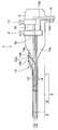
- the bending operation knob 8 is disposed so as to sandwich a virtual plane 8a orthogonal to the rotation axis 8l of the bending operation knob 8.
- a forceps plug connection base 17 is provided in the first introduction port 13h, and a forceps plug 20 can be detachably attached to the forceps plug connection base 17.
- a T-shaped tube connection base 18 is provided in the second introduction port 14h, and a T-shaped tube 30 can be detachably attached to the T-shaped tube connection base 18.
- the forceps plug 20 is made of a resin such as polyethylene or polypropylene having a predetermined elastic force.
- the forceps plug 20 includes a connecting cylinder part 21 and a plug part 22 as shown in FIGS.
- the connecting cylinder part 21 is attached to the forceps plug connection base 17 by the elastic force of the connecting cylinder part 21, and is fixed tightly while maintaining a watertight / airtight state.
- the plug portion 22 is provided with an introduction hole (not shown).
- a treatment tool such as a forceps or a crushed stone tool is introduced into the first channel 13 through the connecting tube portion 21 after passing through the introduction hole by pushing open the slit 23 that is in close contact with the treatment tool.
- the inner peripheral surface of the introduction hole is brought into close contact with the outer peripheral surface of the treatment instrument by the elastic force of the plug portion 22 to maintain a watertight / airtight state. It is like that.
- the T-shaped tube 30 is formed of at least one of a metal and a resin, and mainly includes a main body tube portion 31 and a branch tube portion 32.
- the branch pipe part 32 is provided so as to protrude from the middle part of the main body pipe part 31.
- the central axis (not shown) of the branch pipe part 32 of this embodiment is orthogonal to the central axis (not shown) of the main body pipe part 31.
- Numeral 33 is a main body pipe connecting part.
- the main body pipe connecting portion 33 is, for example, a luer lock, and is rotatably provided on one side of the main body pipe portion 31.
- the main body pipe connecting portion 33 can be attached to and detached from the T-tube connecting base 18 by rotating the connecting portion 33 with respect to the main body pipe portion 31.
- Numeral 34 is a guide wire insertion opening provided on the other side of the main body pipe portion 31.
- the guide wire insertion port 34 is provided with a recess 34a, and a plug member 35 is disposed in the recess 34a.
- the plug member 35 is formed of a resin having a predetermined elastic force and has a through hole for inserting a guide wire.
- the guide wire (not shown) passes through the slit provided in the recess 34 a, then passes through the wire insertion hole of the plug member 35, and then is introduced into the second channel 14 through the main body pipe portion 31.
- the inner peripheral surface of the wire insertion hole is brought into close contact with the outer peripheral surface of the guide wire by the elastic force of the plug member 35, and the watertight / airtight state is maintained. It has become so.
- Numeral 36 is a syringe connection part.
- the syringe connection part 36 includes a rotation part 37, a syringe connection port part 38, and a cock 39.
- the protruding direction of the syringe connection port part 38 can be changed to a desired direction with respect to the central axis of the branch pipe part 32 when the main body pipe connecting part 33 is attached.
- the syringe connection port part 38 is a convex part protruding from a predetermined part of the rotating part 37.
- a syringe (not shown) luer lock is attached to the syringe connection port 38.
- the cock 39 switches between an open state in which the inside of the branch pipe part 32 communicates with the outside via the syringe connection port part 38 and a closed state in which the inside of the branch pipe part 32 and the outside are shut off. That is, in a state where the syringe is connected to the syringe connection port portion 38, when the cock 39 is in an open state, the fluid in the syringe can be supplied into the second channel 14 via the branch tube portion 32 and the main body tube portion 31. It becomes possible. On the other hand, when the cock 39 is closed, when the syringe is removed from the syringe connection port 38, the backflow of body fluid is prevented.
- the inner diameter of the second channel 14 through which the guide wire is inserted is set in advance to be smaller than the inner diameter of the first channel 13 through which the treatment tool is inserted.
- the first introduction port 13b and the second introduction port 14b provided in the introduction convex portion 12 are provided across the virtual plane 8a.
- an area including the operation knob 8 with respect to the virtual plane 8a is an operator area A1
- an area not including the operation knob 8 with respect to the virtual plane 8a is an assistant area A2.
- the first introduction port 13b is disposed in the operator region A1
- the second introduction port 14b is disposed in the assistant region A2.
- the arrow Y2A which is the extension direction of the first introduction port 13b, is inclined with respect to the virtual plane 8a in the operator region A1. Specifically, as the extension distance from the first introduction port 13b increases, the separation distance from the extension point to the longitudinal axis 2a increases.
- the arrow Y2B which is the extending direction of the second introduction port 14b, is inclined with respect to the virtual plane 8a in the assistant area A2. Specifically, as the extension distance from the second introduction port 14b increases, the separation distance from the extension point to the longitudinal axis 2a increases.
- the T-shaped tube 30 is fixedly attached to the T-shaped tube connection base 18 with the opening of the syringe connection port portion 38 provided in the T-shaped tube 30 facing the direction opposite to the virtual plane 8a. That is, it is configured to move away from the virtual plane 8a as the distance from the opening of the syringe connection port portion 38 increases.
- the bending operation knob 8 is disposed on the operation unit left side surface 3L, which is one surface of the operation unit 3.
- the operation unit left side surface 3L is adjacent to the left long side of the operation unit upper surface 3U which is the front of the operation unit 3, and the right long side of the operation unit upper surface 3U is the right side of the operation unit opposite to the operation unit left side surface 3L.
- Surface 3R is adjacent.
- the gas supply button 9 and the suction button 10 are disposed on the operation unit upper surface 3U.
- the operation unit 3 is provided with a gas supply cylinder 3g on which the gas supply button 9 is arranged and a suction cylinder 3s on which the suction button 10 is arranged.
- Reference numeral 19a denotes a first connection tube, and a tip end portion of the first connection tube 19a is connected to a first branch member (not shown) and communicates with the first channel 13.
- the base end portion of the first connection tube 19a is connected to the suction cylinder 3s and communicates with the inside of the cylinder.
- Reference numeral 19b denotes a suction tube, and a distal end portion of the suction tube 19b is connected to the suction cylinder 3s and communicates with the inside of the cylinder, and a proximal end portion is connected to a suction device (not shown).
- the first connection tube 19a and the suction tube 19b constitute a suction conduit.
- reference numeral 19c denotes a second connection tube
- the tip of the second connection tube 19c is connected to a second branch member (not shown) and communicates with the second channel 14.
- the base end portion of the second connection tube 19c is connected to the gas supply cylinder 3g and communicates with the inside of the cylinder.
- Reference numeral 19d denotes a gas tube.
- the distal end of the gas tube 19d is connected to the gas supply cylinder 3g and communicates with the cylinder, and the base end is connected to a gas supply device (not shown).
- the third connecting tube 19c and the gas tube 19d constitute a gas feed conduit.
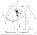
- the grasping portion 3h is grasped by the left hand of the operator 100, and the insertion portion 2 is held by the right hand.
- most of the body of the operator 100 is located on the operator region A1 side.
- the first introduction port 13b is disposed in front of the operator 100 and in front of the chest.
- only the left hand of the operator 100 holding the holding part 3h is arranged on the assistant area A2 side.
- the assistant area A2 side is secured as an area where the assistant 101 works.
- the first introduction port 13b of the introduction convex portion 12 provided in the operation unit 3 of the endoscope 1 is located on the operator region A1 side, and the second introduction port 14b is located on the assistant region A2 side. Yes.
- the extension direction indicated by the arrow Y2A is inclined with respect to the virtual plane 8a as described above, and the distance from the extension point to the virtual plane 8a increases as the extension distance from the first introduction port 13b increases. To do.
- extension direction indicated by the arrow Y2B is inclined with respect to the virtual plane 8a as described above, and as the extension distance from the second introduction port 14b increases, the separation distance from the extension point to the virtual plane 8a increases. To do.
- the assistant 101 located on the assistant area A2 side smoothly does not interfere with the surgeon 100 with the guide wire operation and the syringe feeding simultaneously. Can be done.
- the introduction convex portion 12 provided in the operation portion 3 of the endoscope 1 is provided with the first introduction port 13 b for guiding the treatment instrument into the body via the first channel 13 and the second channel 14.
- the guide wire is introduced into the body and the second introduction port 14 b for feeding the liquid in the syringe is arranged, and the inner diameter of the second channel 14 is set smaller than the inner diameter of the first channel 13. Therefore, the treatment tool handled by the operator and the medical instrument handled by the assistant can be clearly determined from the diameter.
- first introduction port 13b is provided on the operator region A1 side
- second introduction port 14b is provided on the assistant region A2 side
- extension direction of the first introduction port 13b is defined as described above.
- the extending direction of the mouth 14b is defined as described above.
- the standing position and work range of the assistant 101 are set to the assistant area A2
- the operation of the surgeon 100 and the action of the assistant 101 interfere even when the treatment instrument operation and the guide wire operation are performed simultaneously, for example. Can be prevented.
- the opening of the syringe connection port portion 38 of the T-shaped tube 30 attached to the T-shaped tube connection port 18 faces the opposite direction to the virtual plane 8a. Even when the treatment instrument operation and the syringe operation are performed at the same time, it is possible to reliably prevent the operation of the operator 100 and the operation of the assistant 101 from interfering with each other.
- the first introduction port 13b and the second introduction port 14b may be arranged side by side along the direction in which the virtual plane 8a extends, and the first introduction port may be arranged on the side close to the insertion portion. Furthermore, by opening each of the first introduction port 13b and the second introduction port 14b toward the operator region A1 and the assistant region A2 so as to be separated from the virtual plane 8a, as in the above-described embodiment, for example, even if the treatment instrument operation and the guide wire operation are performed simultaneously, it is possible to prevent the operation of the operator 100 and the operation of the assistant 101 from interfering with each other.
Landscapes
- Health & Medical Sciences (AREA)
- Life Sciences & Earth Sciences (AREA)
- Surgery (AREA)
- Biomedical Technology (AREA)
- Medical Informatics (AREA)
- Optics & Photonics (AREA)
- Pathology (AREA)
- Radiology & Medical Imaging (AREA)
- Biophysics (AREA)
- Engineering & Computer Science (AREA)
- Physics & Mathematics (AREA)
- Heart & Thoracic Surgery (AREA)
- Nuclear Medicine, Radiotherapy & Molecular Imaging (AREA)
- Molecular Biology (AREA)
- Animal Behavior & Ethology (AREA)
- General Health & Medical Sciences (AREA)
- Public Health (AREA)
- Veterinary Medicine (AREA)
- Endoscopes (AREA)
- Instruments For Viewing The Inside Of Hollow Bodies (AREA)
Abstract
内視鏡1は、挿入部2と、操作部3と、第1チャンネル13と、第1チャンネル13より内径が小さく設定された第2チャンネル14と、を備え、第1導入口13bと第2導入口14bとを、操作ノブ8の回転軸に対し直交する平面を挟んで並設すると共に、第1導入口13bを前記平面の操作ノブ側に配置した。
Description
本発明は、挿入部内に二つの処置具用チャンネルを備える内視鏡に関する。
内視鏡は、医療分野および工業用分野などにおいて利用されている。内視鏡には、細長で可撓性を備える挿入部の先端側に湾曲部を備えるタイプのものがある。湾曲部を備える内視鏡では、湾曲部を湾曲させることによって、挿入部先端部に設けられている観察光学系の視野方向を変化させて広範囲の観察を行なえる。
また、内視鏡の種類には、観察方向を挿入部の挿入方向前方に設定した直視型の内視鏡や、観察方向を挿入部の挿入方向前方に対して所定の角度傾斜した斜視型や側視型の内視鏡がある。
側視型の内視鏡においては、挿入部の先端部内に処置具起上装置を設けたものがある。処置具起上装置を設けた側視型の内視鏡によれば、挿入部内に設けられた処置具挿通チャンネルに挿入されるガイドワイヤ、造影チューブ、鉗子、電気メスなどの処置具を、処置具起上装置を介して先端部から内視鏡外部に導出させるとき、該処置具起上装置を手元操作して処置具の向きを変更して例えば胆管内に挿入することができる。
近年においては、挿入部の細径化に伴い、経鼻・経口挿入に対応した直視型内視鏡の挿入部を経口的に胆管内に挿入して処置を行なう直接的経口胆管鏡下の手技が行なわれている。
しかし、直視型内視鏡の挿入部を胆管内に挿入する手技や、胆管内で処置を行なう手技は、熟練を要する。このため、効率的に挿入手技や処置手技を行なえる内視鏡が求められている。
例えば、日本国実開平2-126603号公報では、処置具の交換を何回も行なうことの煩わしさを解消するため、異なる処置具を挿通可能な二つの処置具チャンネルを設けた内視鏡が提案されている。また、日本国特開平10-174674号公報では、内径の大きさが異なる複数の鉗子チャンネルが設けられた内視鏡において、チャンネル太さを誰でもが容易かつ的確に判別することができる内視鏡が提案されている。
しかしながら、日本国実開平2-126603号公報、日本国特開平10-174674号公報に示された2チャンネルタイプの内視鏡では、直接的経口胆管鏡下の手技が考慮されていない。したがって、直接的経口胆管鏡下の手技の際、内視鏡を操作する術者と、該手技を補助する補助者とが、処置具操作、シリンジ送液、ガイドワイヤ操作、吸引操作、送ガス操作などを同時にストレス無く効率的に行なうことが難しかった。
本発明は上記事情に鑑みてなされたものであり、直接的経口胆管鏡下の手技において、術者による処置具操作と補助者によるシリンジ送液およびガイドワイヤ操作とを同時に行なったとしても、これらの操作が互いに干渉すること無くスムーズに行なえる内視鏡を提供することを目的にしている。
本発明の一態様の内視鏡は、長手軸に沿って延びる細長な挿入部と、前記挿入部の基端側に設けられ、操作者により回転操作される操作ノブが設けられた操作部と、前記操作部もしくは操作部近傍に第1導入口を有する一方、前記挿入部の先端側の面に第1導出口を有する、予め定めた内径に設定された第1管路と、前記挿入部内において前記第1管路と並行に挿通配置され、前記操作部もしくは該操作部近傍に第2導入口を有する一方、前記挿入部の先端側の面に第2導出口を有する、前記第1管路より内径が小さく設定された第2管路と、を備えた内視鏡であって、前記第1導入口と第2導入口とを、前記操作ノブの回転軸に対し直交する平面を挟んで並設すると共に、前記第1導入口を前記平面の前記操作ノブ側に配置したことを特徴とする。
本発明の他態様の内視鏡は、長手軸に沿って延びる細長な挿入部と、前記挿入部の基端側に設けられ、操作者により回転操作される操作ノブが設けられた操作部と、前記操作部もしくは操作部近傍に第1導入口を有する一方、前記挿入部の先端側の面に第1導出口を有する、予め定めた内径に設定された第1管路と、前記挿入部内において前記第1管路と並行に挿通配置され、前記操作部もしくは該操作部近傍に第2導入口を有する一方、前記挿入部の先端側の面に第2導出口を有する、前記第1管路より内径が小さく設定された第2管路と、を備えた内視鏡であって、前記第1導入口と第2導入口とを、前記操作ノブの回転軸に対し直交する平面に沿って並設すると共に、前記第1導入口を前記挿入部に近接する側に配置したことを特徴とする。
以下、図面を参照して本発明の実施の形態を説明する。なお、以下の説明に用いる各図面は、模式的に示すものであり、各構成要素を図面上で認識可能な程度に示すために、各部材の寸法関係や縮尺などは、構成要素毎に異ならせて示している場合がある。したがって、本発明は、これらの図面に記載された構成要素の数量、構成要素の形状、構成要素の大きさの比率および各構成要素の相対的な位置関係など、図示の形態のみに限定されるものではない。
図1に示すように内視鏡1は、長手軸に沿って延出されて細長で可撓性を有する挿入部2と、この挿入部2の基端部に連設した操作部3と、この操作部3の側部から延出する可撓性を有するユニバーサルコード4と、を備えて構成されている。ユニバーサルコード4の基端部には、外部装置である図示しない光源装置、ビデオプロセッサなどに接続されるコネクタが設けられている。
挿入部2は、先端側から順に、先端部5と、複数の湾曲駒を回動自在に連接して湾曲自在な湾曲部6と、柔軟性を有する可撓管部7と、を備えている。操作部3には所定の軸周りに回転操作される湾曲操作ノブ8、送ガスボタン9、吸引ボタン10、複数のリモートスイッチ11、導入凸部12が設けられている。導入凸部12は、処置具用凸部であって、操作部3もしくは操作部3近傍に設けられている。
先端部5の先端面5aには、先端面拡大図に示すように、第1管路である第1チャンネル13の第1導出口13aと第2管路である第2チャンネル14の第2導出口14aとが設けられている。一方、導入凸部12には第1チャンネル13の第1導入口13bと、第2チャンネル14の第2導入口14bと、が設けられている。なお、符号15は観察レンズであって観察光学系を構成する。符号16は照明レンズであって照明光学系を構成する。術者は、内視鏡1を取り扱う際、一般に、左手で把持部3hを把持し、右手で挿入部2を保持する。
挿入部2内に挿通された挿入部内拡大図に示す湾曲ワイヤ6a,6bは、湾曲操作ノブ8の回動操作に伴って牽引弛緩される。この結果、湾曲部6が操作者の意図する方向に湾曲する。挿入部2内において、第1チャンネル13と第2チャンネル14とは並行に配置されている。
送ガスボタン9は、送ガス用シリンダ(図3の符号3g)内に配置され、空気や炭酸ガスなどの気体供給・停止を行なう動作を指示する。一方、吸引ボタン10は、吸引用シリンダ(図3の符号3s)内に配置され、操作されることによって体液や汚物を吸引する動作を指示する。
複数のリモートスイッチ11には、表示装置(不図示)の画面上に表示されている内視鏡画像の停止を指示する機能の動作指示や、記録を指示する機能や画像の拡大を指示する機能、照明光の切り換えを指示する機能の動作指示が割り当てられている。
導入凸部12は、例えば操作部3の把持部3h近傍の外周面から外方に斜めに突出して設けられている。第1導入口13bと第2導入口14bは導入凸部12の基端部の一面12a上に配列されている。
第1導入口13bの第1中心O1と第2導入口14bの第2中心O2とは、図2に示すように、導入凸部12の基端部の一面12a上の仮想線である開口配置直線Lに沿って、湾曲操作ノブ8の回転軸8lに対し直交する仮想平面8aを挟むように配置される。
本実施形態において、第1導入口13hには鉗子栓接続口金17が設けられ、該鉗子栓接続口金17には鉗子栓20が着脱自在に取り付け可能になっている。一方、第2導入口14hにはT字管接続口金18が設けられ、該T字管接続口金18にはT字管30が着脱自在に取り付け可能になっている。
鉗子栓20は、予め定めた弾性力を有する、ポリエチレンやポリプロピレンなどの樹脂製である。鉗子栓20は、図1、図2に示すように連結筒部21および栓部22を備えている。連結筒部21は、該連結筒部21が有する弾性力によって鉗子栓接続口金17に取り付けられ、水密・気密状態を保持して密着固定される。
栓部22には導入孔(不図示)が設けられている。鉗子、砕石具などの処置具(不図示)は、密着したスリット23を押し開いて導入孔に導かれ、該導入孔を通過した後、連結筒部21内を経て第1チャンネル13に導入される。
処置具を第1チャンネル13内に挿通させた処置具挿通状態において、導入孔の内周面が栓部22の有する弾性力によって処置具の外周面に密着して水密・気密状態が保持されるようになっている。
T字管30は、金属と樹脂の少なくとも一方で形成されており、本体管部31と、分岐管部32と、を主に有する。分岐管部32は、本体管部31の中途部から突出して設けられている。そして、本実施形態の分岐管部32の中心軸(不図示)は、本体管部31の中心軸(不図示)に対して直交している。
符号33は、本体管連結部である。本体管連結部33は、例えばルアーロックであって本体管部31の一方側に回動自在に設けられている。本体管連結部33は、該連結部33を本体管部31に対して回転させることによってT字管接続口金18に対する取り付け取り外しが可能である。
符号34は、ガイドワイヤ挿入口部であって、本体管部31の他方側に設けられている。ガイドワイヤ挿入口部34には凹部34aが設けられ、該凹部34a内には栓部材35が配設される。栓部材35は、予め定めた弾性力を有する樹脂で形成され、ガイドワイヤを挿通するための貫通孔を有している。
ガイドワイヤ(不図示)は、凹部34aに設けられたスリットを通過した後、栓部材35のワイヤ挿通孔を通過した後、本体管部31内を経て第2チャンネル14内に導入されていく。ガイドワイヤを第2チャンネル14内に挿通させたガイドワイヤ挿通状態において、ワイヤ挿通孔の内周面が栓部材35の有する弾性力によってガイドワイヤの外周面に密着して水密・気密状態が保持されるようになっている。
符号36は、シリンジ接続部である。シリンジ接続部36は、回動部37、シリンジ接続口部38、コック39を備えている。シリンジ接続口部38の突出方向は本体管連結部33による取り付け時に分岐管部32の中心軸に対して所望する方向に変更することが可能である。
シリンジ接続口部38は、回動部37の予め定めた部位から突出した凸部である。シリンジ接続口部38にはシリンジ(不図示)のルアーロックが取り付けられるようになっている。
コック39は、分岐管部32内がシリンジ接続口部38を介して外部に対して連通した開放状態と、分岐管部32内と外部とが遮断された閉塞状態とに切り換える。すなわち、シリンジ接続口部38にシリンジを接続した状態において、コック39が開放状態のとき、シリンジ内の流体を分岐管部32、本体管部31を介して第2チャンネル14内へ供給することが可能になる。また、一方、コック39を閉塞状態にすることによって、シリンジをシリンジ接続口部38から取り外した際、体液の逆流が防止される。
このように、T字管30を介して体内に、ガイドワイヤを導出させること、および、シリンジの液体を供給すること、が可能になっている。
そして、本実施形態において、ガイドワイヤが挿通される第2チャンネル14の内径は、処置具が挿通される第1チャンネル13の内径に比べて予め小径に設定してある。
導入凸部12に設けられた第1導入口13bと第2導入口14bとは、仮想平面8aを挟んで設けられている。
本実施形態においては、仮想平面8aに対して、操作ノブ8を含む領域を術者領域A1とし、仮想平面8aに対して操作ノブ8を含まない領域を補助者領域A2としている。そして、第1導入口13bは術者領域A1に配置され、第2導入口14bは補助者領域A2に配置されている。
第1導入口13bの延長方向である矢印Y2Aは、術者領域A1内であって仮想平面8aに対して傾いている。具体的には、第1導入口13bからの延長距離が増加するにつれて、その延長点から長手軸2aに至る離間距離が増大するよう構成されている。
一方、第2導入口14bの延長方向である矢印Y2Bは、補助者領域A2内であって仮想平面8aに対して傾いている。具体的には、第2導入口14bからの延長距離が増加するにつれて、その延長点から長手軸2aに至る離間距離が増大するよう構成されている。
そして、T字管30は、該T字管30に設けられたシリンジ接続口部38の開口を仮想平面8aとは反対方向に向けてT字管接続口金18に取り付け固定されている。つまり、シリンジ接続口部38の開口から離れるにしたがって仮想平面8aから遠ざかるよう構成されている。
なお、湾曲操作ノブ8は、操作部3の一面である操作部左側面3Lに配置されている。操作部左側面3Lは、操作部3の正面である操作部上面3Uの左長辺に隣設し、操作部上面3Uの右長辺には操作部左側面3Lの反対面である操作部右側面3Rが隣設している。本実施形態において、操作部上面3Uには送ガスボタン9および吸引ボタン10などが配設されている。
図3に示すように操作部3には送ガスボタン9が配置される送ガス用シリンダ3gと、吸引ボタン10が配置される吸引用シリンダ3sと、が設けられている。
符号19aは、第1連結チューブであって、第1連結チューブ19aの先端部は、第1分岐部材(不図示)に連結されて第1チャンネル13に連通している。第1連結チューブ19aの基端部は、吸引用シリンダ3sに連結されてシリンダ内に連通している。符号19bは、吸引チューブであって、吸引チューブ19bの先端部は、吸引用シリンダ3sに連結されてシリンダ内に連通し、基端部は吸引装置(不図示)に接続されている。第1連結チューブ19aと吸引チューブ19bとは吸引用管路を構成している。
一方、符号19cは、第2連結チューブであって、第2連結チューブ19cの先端部は、第2分岐部材(不図示)に連結されて第2チャンネル14に連通している。第2連結チューブ19cの基端部は、送ガス用シリンダ3gに連結されてシリンダ内に連通している。符号19dは、ガスチューブであって、ガスチューブ19dの先端部は、送ガス用シリンダ3gに連結されてシリンダ内に連通し、基端部は送ガス装置(不図示)に接続されている。第3連結チューブ19cとガスチューブ19dとは送ガス用管路を構成している。
図4に示すように内視鏡1は、術者100の左手で把持部3hが把持され、右手で挿入部2が保持される。この操作部把持状態のとき、術者100の身体の大部分は、術者領域A1側に位置する。そして、術者100の略胸前であって手前に第1導入口13bが配置される。言い換えれば、補助者領域A2側には把持部3hを把持する術者100の左手だけが配置される。この結果、補助者領域A2側は、補助者101が作業する領域として確保される。
また、内視鏡1の操作部3に設けられた導入凸部12の第1導入口13bは、術者領域A1側に位置し、第2導入口14bは補助者領域A2側に位置している。加えて、矢印Y2Aで示す延長方向は、上述したように仮想平面8aに対して傾き、第1導入口13bからの延長距離が増加するにつれて、その延長点から仮想平面8aに至る離間距離が増大する。
逆に、矢印Y2Bで示す延長方向は、上述したように仮想平面8aに対して傾き、第2導入口14bからの延長距離が増加するにつれて、その延長点から仮想平面8aに至る離間距離が増大する。
この結果、例えば、術者100が右手で例えば鉗子を手元操作するとき、補助者領域A2側に位置する補助者101が同時にガイドワイヤ操作やシリンジ送液を術者100に干渉すること無く、スムーズに行なうことができる。
このように、内視鏡1の操作部3に設けられた導入凸部12に、第1チャンネル13を介して処置具を体内に導くための第1導入口13bと、第2チャンネル14を介してガイドワイヤの体内への導入やシリンジ内の液体を送液するための第2導入口14bとを配列し、第2チャンネル14の内径を第1チャンネル13の内径より小さく設定している。したがって、術者が取り扱う処置具と、補助者が取り扱う医療器具と、を径寸法から明確に判断できる。
また、第1導入口13bを術者領域A1側に設け、第2導入口14bを補助者領域A2側に設けると共に、第1導入口13bの延長方向を上述のように規定し、第2導入口14bの延長方向を上述のように規定している。
したがって、第1導入口13bを介して体内に導出される処置具の該第1導入口13bから外部に導出されている処置具基端部分と、第2導入口14bを介して体内に導出されるガイドワイヤの該第2導入口14bから外部に導出されているワイヤ基端部分と、が干渉することを確実に防止することができる。
加えて、補助者101の立ち位置および作業範囲を補助者領域A2側にしたことによって、例えば処置具操作とガイドワイヤ操作を同時に行なっても、術者100の動作と補助者101の動作が干渉することを防止できる。
なお、補助者101がシリンジ操作を行なった場合においても、T字管接続口金18に取り付けられたT字管30のシリンジ接続口部38の開口が仮想平面8aとは反対方向を向いているため、同時に処置具操作とシリンジ操作とを行なった場合であっても術者100の動作と補助者101の動作とが干渉することを確実に防止できる。
尚、本発明は、以上述べた実施形態のみに限定されるものではなく、発明の要旨を逸脱しない範囲で種々変形実施可能である。
例えば前記第1導入口13bと第2導入口14bを前記仮想平面8aが広がる方向に沿って並べて配置し、前記第1導入口を前記挿入部に近接する側に配置しても良い。さらにこれら第1導入口13b及び第2導入口14bそれぞれを、前記仮想平面8aから離間するよう術者領域A1側及び補助者領域A2に向けて開口させることで、前述した実施形態と同様に、例えば処置具操作とガイドワイヤ操作を同時に行なっても、術者100の動作と補助者101の動作が干渉することを防止できる。
本発明によれば、直接的経口胆管鏡下の手技の際、術者による処置具操作と補助者によるシリンジ送液およびガイドワイヤ操作とを同時に行なったとしても、これら操作が互いに干渉すること無くスムーズに行なえる内視鏡を実現できる。
本出願は、2015年12月2日に日本国に出願された特願2015-235968号を優先権主張の基礎として出願するものであり、上記の開示内容は、本願明細書、請求の範囲に引用されるものとする。
Claims (10)
- 長手軸に沿って延びる細長な挿入部と、
前記挿入部の基端側に設けられ、操作者により回転操作される操作ノブが設けられた操作部と、
前記操作部もしくは操作部近傍に第1導入口を有する一方、前記挿入部の先端側の面に第1導出口を有する、予め定めた内径に設定された第1管路と、
前記挿入部内において前記第1管路と並行に挿通配置され、前記操作部もしくは該操作部近傍に第2導入口を有する一方、前記挿入部の先端側の面に第2導出口を有する、前記第1管路より内径が小さく設定された第2管路と、
を備えた内視鏡であって、
前記第1導入口と第2導入口とを、前記操作ノブの回転軸に対し直交する平面を挟んで並設すると共に、前記第1導入口を前記平面の前記操作ノブ側に配置した、
ことを特徴とする内視鏡。 - 長手軸に沿って延びる細長な挿入部と、
前記挿入部の基端側に設けられ、操作者により回転操作される操作ノブが設けられた操作部と、
前記操作部もしくは操作部近傍に第1導入口を有する一方、前記挿入部の先端側の面に第1導出口を有する、予め定めた内径に設定された第1管路と、
前記挿入部内において前記第1管路と並行に挿通配置され、前記操作部もしくは該操作部近傍に第2導入口を有する一方、前記挿入部の先端側の面に第2導出口を有する、前記第1管路より内径が小さく設定された第2管路と、
を備えた内視鏡であって、
前記第1導入口と第2導入口とを、前記操作ノブの回転軸に対し直交する平面に沿って並設すると共に、前記第1導入口を前記挿入部に近接する側に配置した、
ことを特徴とする内視鏡。 - 前記第1導入口は、観察対象物に対し処置を行なうための処置具を導入するための開口であって、前記第2導入口は、前記処置具より小径に形成されたガイドワイヤを導入するための開口もしくは流体を供給するための開口であることを特徴とする、請求項1に記載された内視鏡。
- 前記第1管路の中間部に吸引ポンプに至る他の管路が接続されたことを特徴とする請求項1に記載された内視鏡。
- 前記第2管路の中間部に気体供給手段から導出される他の管路が接続されたことを特徴とする請求項1に記載された内視鏡。
- 前記第2管路の前記第2導入口には、ガイドワイヤ挿通口と流体供給口を供えた接続器具が接続されることを特徴とする請求項3に記載された内視鏡。
- 前記接続器具のガイドワイヤ挿通口から延出される前記ガイドワイヤは、前記平面から離れる方向に延出されていることを特徴とする請求項6に記載された内視鏡。
- 前記流体供給口の開口は、前記平面から離れる方向に向けて設けられていることを特徴とする、請求項6に記載された内視鏡。
- 前記第1導入口と第2導入口は、それぞれ前記平面から離間する方向に向いて開口していることを特徴とする、請求項1に記載された内視鏡。
- 前記第1導入口と第2導入口は、それぞれ前記平面から離間するよう逆方向に向いて開口していることを特徴とする、請求項1に記載された内視鏡。
Applications Claiming Priority (2)
| Application Number | Priority Date | Filing Date | Title |
|---|---|---|---|
| JP2015-235968 | 2015-12-02 | ||
| JP2015235968 | 2015-12-02 |
Publications (1)
| Publication Number | Publication Date |
|---|---|
| WO2017094340A1 true WO2017094340A1 (ja) | 2017-06-08 |
Family
ID=58796944
Family Applications (1)
| Application Number | Title | Priority Date | Filing Date |
|---|---|---|---|
| PCT/JP2016/079065 Ceased WO2017094340A1 (ja) | 2015-12-02 | 2016-09-30 | 内視鏡 |
Country Status (1)
| Country | Link |
|---|---|
| WO (1) | WO2017094340A1 (ja) |
Citations (5)
| Publication number | Priority date | Publication date | Assignee | Title |
|---|---|---|---|---|
| JPH10174674A (ja) * | 1996-12-18 | 1998-06-30 | Asahi Optical Co Ltd | 内視鏡 |
| JP2001170006A (ja) * | 1999-12-15 | 2001-06-26 | Olympus Optical Co Ltd | 内視鏡 |
| JP2005058749A (ja) * | 2003-07-29 | 2005-03-10 | Olympus Corp | 内視鏡用アダプター及び内視鏡 |
| JP2012245284A (ja) * | 2011-05-31 | 2012-12-13 | Hoya Corp | 内視鏡システム |
| JP2014223107A (ja) * | 2013-05-15 | 2014-12-04 | 富士システムズ株式会社 | 内視鏡用スライディングチューブ |
-
2016
- 2016-09-30 WO PCT/JP2016/079065 patent/WO2017094340A1/ja not_active Ceased
Patent Citations (5)
| Publication number | Priority date | Publication date | Assignee | Title |
|---|---|---|---|---|
| JPH10174674A (ja) * | 1996-12-18 | 1998-06-30 | Asahi Optical Co Ltd | 内視鏡 |
| JP2001170006A (ja) * | 1999-12-15 | 2001-06-26 | Olympus Optical Co Ltd | 内視鏡 |
| JP2005058749A (ja) * | 2003-07-29 | 2005-03-10 | Olympus Corp | 内視鏡用アダプター及び内視鏡 |
| JP2012245284A (ja) * | 2011-05-31 | 2012-12-13 | Hoya Corp | 内視鏡システム |
| JP2014223107A (ja) * | 2013-05-15 | 2014-12-04 | 富士システムズ株式会社 | 内視鏡用スライディングチューブ |
Similar Documents
| Publication | Publication Date | Title |
|---|---|---|
| US11432709B2 (en) | Endoscope system | |
| US20230355272A1 (en) | Surgical instrument guide with insufflation channels | |
| US10524640B2 (en) | Endoscopic treatment instrument, treatment instrument unit, and treatment system | |
| JP2005137423A (ja) | 内視鏡用の外付けチャンネルおよび外付けチャンネル用分岐部材 | |
| CN106659363B (zh) | 内窥镜操作部和内窥镜 | |
| JP2001095747A (ja) | 電子内視鏡 | |
| JP5933872B1 (ja) | 内視鏡 | |
| JP7158950B2 (ja) | 内視鏡補助具、内視鏡、内視鏡補助具及び内視鏡 | |
| WO2005122865A1 (ja) | 内視鏡及び内視鏡用湾曲操作補助部材 | |
| WO2006106881A1 (ja) | 内視鏡 | |
| CN105813539B (zh) | 用于内窥镜用引导部件的保持机构和内窥镜 | |
| JP6049950B2 (ja) | 内視鏡 | |
| CN104703530B (zh) | 内窥镜 | |
| US20210068637A1 (en) | Endoscope and channel tube | |
| WO2017094340A1 (ja) | 内視鏡 | |
| JP4441232B2 (ja) | 外付けチャンネル及びこれを備えた内視鏡装置 | |
| JP6279169B1 (ja) | 内視鏡 | |
| JP7597629B2 (ja) | 内視鏡 | |
| WO2015174128A1 (ja) | 内視鏡 | |
| JP7662699B2 (ja) | 手術補助器具 | |
| JP6747800B2 (ja) | 処置具挿通具 | |
| CN115137280A (zh) | 内窥镜 | |
| WO2023120255A1 (ja) | オーバーシース及び内視鏡用処置具装置並びに内視鏡用器具 | |
| JP2007195688A (ja) | 内視鏡挿入補助具 | |
| CN115137279A (zh) | 内窥镜 |
Legal Events
| Date | Code | Title | Description |
|---|---|---|---|
| 121 | Ep: the epo has been informed by wipo that ep was designated in this application |
Ref document number: 16870280 Country of ref document: EP Kind code of ref document: A1 |
|
| NENP | Non-entry into the national phase |
Ref country code: DE |
|
| 122 | Ep: pct application non-entry in european phase |
Ref document number: 16870280 Country of ref document: EP Kind code of ref document: A1 |
|
| NENP | Non-entry into the national phase |
Ref country code: JP |