WO2017094093A1 - 無停電電源装置 - Google Patents
無停電電源装置 Download PDFInfo
- Publication number
- WO2017094093A1 WO2017094093A1 PCT/JP2015/083682 JP2015083682W WO2017094093A1 WO 2017094093 A1 WO2017094093 A1 WO 2017094093A1 JP 2015083682 W JP2015083682 W JP 2015083682W WO 2017094093 A1 WO2017094093 A1 WO 2017094093A1
- Authority
- WO
- WIPO (PCT)
- Prior art keywords
- switches
- currents
- power supply
- value
- power
- Prior art date
- Legal status (The legal status is an assumption and is not a legal conclusion. Google has not performed a legal analysis and makes no representation as to the accuracy of the status listed.)
- Ceased
Links
Images



Classifications
-
- H—ELECTRICITY
- H02—GENERATION; CONVERSION OR DISTRIBUTION OF ELECTRIC POWER
- H02J—ELECTRIC POWER NETWORKS; CIRCUIT ARRANGEMENTS OR SYSTEMS FOR SUPPLYING OR DISTRIBUTING ELECTRIC POWER; SYSTEMS FOR STORING ELECTRIC ENERGY
- H02J9/00—Circuit arrangements for emergency or stand-by power supply, e.g. for emergency lighting
- H02J9/04—Circuit arrangements for emergency or stand-by power supply, e.g. for emergency lighting in which the distribution system is disconnected from the normal source and connected to a standby source
- H02J9/06—Circuit arrangements for emergency or stand-by power supply, e.g. for emergency lighting in which the distribution system is disconnected from the normal source and connected to a standby source with automatic change-over, e.g. UPS systems
- H02J9/062—Circuit arrangements for emergency or stand-by power supply, e.g. for emergency lighting in which the distribution system is disconnected from the normal source and connected to a standby source with automatic change-over, e.g. UPS systems for AC powered loads
-
- H—ELECTRICITY
- H02—GENERATION; CONVERSION OR DISTRIBUTION OF ELECTRIC POWER
- H02J—ELECTRIC POWER NETWORKS; CIRCUIT ARRANGEMENTS OR SYSTEMS FOR SUPPLYING OR DISTRIBUTING ELECTRIC POWER; SYSTEMS FOR STORING ELECTRIC ENERGY
- H02J9/00—Circuit arrangements for emergency or stand-by power supply, e.g. for emergency lighting
- H02J9/04—Circuit arrangements for emergency or stand-by power supply, e.g. for emergency lighting in which the distribution system is disconnected from the normal source and connected to a standby source
- H02J9/06—Circuit arrangements for emergency or stand-by power supply, e.g. for emergency lighting in which the distribution system is disconnected from the normal source and connected to a standby source with automatic change-over, e.g. UPS systems
Definitions
- the present invention relates to an uninterruptible power supply, and more particularly to an uninterruptible power supply of a constant commercial power supply system.
- An uninterruptible power supply of a constant commercial power supply system includes a switch having a first terminal receiving AC power from a commercial AC power supply, a second terminal connected to a load, and a power converter connected to the load. .
- the switch When the AC voltage from the commercial AC power supply is normal, the switch is turned on, and the AC power from the commercial AC power supply is supplied to the load via the switch.
- the switch When the AC voltage from the commercial AC power supply becomes abnormal, the switch is turned off, and the DC power supplied from the DC power supply is converted into AC power by the power converter and supplied to the load.
- Patent Document 1 JP-A-11-341686 (Patent Document 1) and JP-A-2003-333753 (Patent Document 2), a switch that does not have a self-extinguishing capability is used, and the AC voltage from the commercial AC power supply becomes abnormal.
- Patent Document 2 a technique is disclosed in which the output current of the power converter is controlled to reduce the current flowing through the switch so that the switch is extinguished quickly.
- Patent Documents 1 and 2 disclose a single-phase uninterruptible power supply, but do not disclose a three-phase uninterruptible power supply.
- When configuring a three-phase uninterruptible power supply simply providing three single-phase uninterruptible power supplies makes the three-phase operation unbalanced and unstable.
- the main object of the present invention is to provide a three-phase uninterruptible power supply that operates stably.
- the uninterruptible power supply according to the present invention is a continuous commercial power supply type uninterruptible power supply, comprising first to third output terminals for supplying a three-phase alternating current to a load, and the first terminals thereof Receive a three-phase AC voltage from a commercial AC power source, and their second terminals are connected to the first to third output terminals, respectively.
- the first to third power converters connected to the first to third output terminals and driven by the DC power supplied from the DC power supply, and the three-phase AC voltage from the commercial AC power supply become abnormal Of the abnormality detector for detecting the current, the first to third current detectors for detecting the instantaneous values of the currents flowing through the first to third switches, the abnormality detector and the first to third current detectors, respectively.
- the first to third switches and the first to third switches In which a control circuit for controlling the converter.
- the first to third switches When the three-phase AC voltage from the commercial AC power supply is normal, the first to third switches are turned on, and the three-phase AC current is applied to the load from the commercial AC power supply through the first to third switches. Supplied.
- an OFF command signal is given from the control circuit to the first to third switches, and the first to third power converters respectively
- the third DC current is output, the first to third switches are extinguished, and further, the three-phase AC current is supplied from the first to third power converters to the load, and the operation of the load is continued. .
- the polarity of the current flowing from the first terminal to the second terminal of each of the first to third switches is positive, and the first to third output terminals from the first to third power converters, respectively. If the polarity of the current flowing toward is positive, the polarity of the first to third DC currents is the same as the polarity of the current flowing through the first to third switches, respectively. The sum of the DC current values is set to zero.
- Another uninterruptible power supply apparatus is an uninterruptible power supply apparatus of a constantly commercial power supply system, and includes first to third output terminals for supplying a three-phase alternating current to a load, and first of them.
- First to third switches having no self-extinguishing capability, each of which receives a three-phase AC voltage from a commercial AC power source and whose second terminals are connected to the first to third output terminals, respectively.
- the first to third power converters connected to the first to third output terminals and driven by the DC power supplied from the DC power supply, and the three-phase AC voltage from the commercial AC power supply become abnormal.
- An abnormality detector for detecting the occurrence of an abnormality, first to third current detectors for detecting instantaneous values of currents flowing through the first to third switches, respectively, an abnormality detector, and first to third current detections.
- the first to third switches and the first to third switches based on the detector detection results
- a control circuit for controlling the power converter.
- the uninterruptible power supply when the three-phase AC voltage from the commercial AC power supply becomes abnormal, an OFF command signal is given to the first to third switches and the first to third powers are supplied. First to third DC currents are output from the converter, the first to third switches are extinguished, and the sum of the values of the first to third DC currents is set to zero. Therefore, the three-phase operation can be balanced, and a three-phase uninterruptible power supply that operates stably can be realized.
- an OFF command signal is given to the first to third switches, and the first to third switches
- the output currents of the first to third power converters are controlled so that the currents flowing through the switches become the first to third DC currents, respectively, the first to third switches are extinguished, and the first to third switches are extinguished.
- the sum of the values of the third DC current is set to zero. Therefore, the three-phase operation can be balanced, and a three-phase uninterruptible power supply that operates stably can be realized.
- FIG. 2 is a block diagram illustrating a configuration of a control circuit illustrated in FIG. 1.
- FIG. 3 is a circuit block diagram illustrating a configuration of a current command unit illustrated in FIG. 2. It is a block diagram which shows the structure of the control circuit contained in the uninterruptible power supply by Embodiment 2 of this invention.
- FIG. 5 is a circuit block diagram showing a configuration of a switch current command unit 30 shown in FIG. 4.
- FIG. 1 is a circuit block diagram showing an overall configuration of an uninterruptible power supply according to Embodiment 1 of the present invention.
- this uninterruptible power supply is a continuous commercial power supply type uninterruptible power supply, which includes input terminals TI1 to TI3, output terminals TO1 to TO3, switches 1a to 1c, power converters 2a to 2c, and abnormality detection. 3, current detectors 4 a to 4 c, 5 a to 5 c, and a control circuit 6.
- the input terminals TI1 to TI3 receive the three-phase AC voltages Vi1 to Vi3 supplied from the commercial AC power supply 51, respectively.
- the output terminals TO1 to TO3 are connected to the load 52 in order to supply a three-phase alternating current to the load 52.
- the first terminals of the switches 1a to 1c are connected to the input terminals TI1 to TI3, respectively, and their second terminals are connected to the output terminals TO1 to TO3, respectively.
- Each of the switches 1a to 1c is a switch having no self-extinguishing capability, and includes, for example, a pair of thyristors.
- the anode and cathode of one thyristor of the pair of thyristors are connected to the first and second terminals, respectively, and the anode and cathode of the other thyristor are connected to the second and first terminals, respectively.
- Each of the switches 1a to 1c may be a mechanical switch.
- the switches 1a to 1c are controlled by the control circuit 6, and are normally turned on when the three-phase AC voltages Vi1 to Vi3 supplied from the commercial AC power supply 51 are normal, and the three-phase power supplied from the commercial AC power supply 51 When AC voltages Vi1 to Vi3 become abnormal (for example, during a power failure), they are turned off.
- the power converters 4a to 4c are connected to the output terminals TO1 to TO3, respectively, and are driven by the DC power supplied from the DC power supply 53.
- the power converters 4a to 4c are controlled by PWM (Pulse Width Modulation) signals ⁇ 6a to ⁇ 6c supplied from the control circuit 6, respectively.
- PWM Pulse Width Modulation
- Each of power converters 4a-4c outputs a desired current among positive DC current, negative DC current, and AC current.
- the power converters 4a to 4c are set to a standby state in which no current is output when the three-phase AC voltages Vi1 to Vi3 supplied from the commercial AC power supply 51 are normal.
- Each of the power converters 4a to 4c responds by outputting a DC current having the same polarity as the current flowing through the corresponding switch when the three-phase AC voltages Vi1 to Vi3 supplied from the commercial AC power supply 51 become abnormal. Turn off the switch quickly.
- the sum of the output currents Io1 to Io3 of the power converters 4a to 4c is set to 0A. Further, the power converters 4a to 4c supply the three-phase alternating current to the load 52 after the switches 1a to 1c are extinguished.
- the abnormality detector 3 detects whether or not the three-phase AC voltages Vi1 to Vi3 supplied from the commercial AC power supply 51 are normal. When the three-phase AC voltages Vi1 to Vi3 are normal, the abnormality detector 3 outputs an abnormality detection signal ⁇ 3. When the three-phase AC voltages Vi1 to Vi3 become abnormal, the abnormality detection signal ⁇ 3 is set to the activation level “H”. For example, at the time of a power failure in which the supply of three-phase AC power from the commercial AC power supply 51 is stopped, the effective values of the three-phase AC voltages Vi1 to Vi3 decrease, and the abnormality detection signal ⁇ 3 is set to the activation level “H” level. .
- the current detectors 4a to 4c are provided between the input terminals TI1 to TI3 and the switches 1a to 1c, detect the instantaneous values of the currents Is1 to Is3 flowing through the switches 1a to 1c, respectively, and signals ⁇ 4a to ⁇ 4c indicating the detected values. Is output.
- the polarity of current flowing from the input terminals TI1 to TI3 to the output terminals TO1 to TO3 (that is, the polarity of current flowing from the first terminal to the second terminal of the switches 1a to 1c) ) Is positive.
- the current detectors 5a to 5c are provided between the power converters 2a to 2c and the output terminals TO1 to TO3, detect the instantaneous values of the output currents Io1 to Io3 of the power converters 2a to 2c, respectively, and indicate the detected values Signals ⁇ 5a to ⁇ 5c are output.
- the polarity of the current flowing from the power converters 2a to 2c toward the output terminals TO1 to TO3 is positive.
- the control circuit 6 outputs the output signal ⁇ 3 of the abnormality detector 3, the output signals ⁇ 4a to ⁇ 4c of the current detectors 4a to 4c, the output signals ⁇ 5a to 5c of the current detectors 5a to 5c, and the voltages Vo1 to Vo3 of the output terminals TO1 to TO3.
- the switches 1a to 1c and the power converters 2a to 2c are controlled on the basis of the instantaneous value.
- the control circuit 6 gives an ON command signal to the switches 1a to 1c to turn it on.
- a three-phase AC current is supplied from the commercial AC power supply 51 to the load 52 via the switches 1a to 1c, and the load 52 is operated.
- the control circuit 6 When the abnormality detection signal ⁇ 3 is set to the “H” level of the activation level, the control circuit 6 provides an off command signal to the switches 1a to 1c and directs the power from the power converters 2a to 2c to the output terminals TO1 to TO3. A current is output to quickly extinguish the switches 1a to 1c. At this time, the polarities of the output currents Io1 to Io3 of the power converters 2a to 2c are the same as the polarities of the currents Is1 to Is3 flowing in the switches 1a to 1c, respectively, and the output currents Io1 to Io3 of the power converters 2a to 2c are the same. The sum of the values is zero.
- control circuit 6 supplies the three-phase alternating current from the power converters 2a to 2c to the load 52 to continue the operation of the load 52.
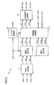
- FIG. 2 is a block diagram showing the configuration of the control circuit 6.
- the control circuit 6 includes a switch control unit 10, a sign determination unit 11, a current command unit 12, a voltage command unit 13, a converter control unit 14, and a PWM signal generation unit 15.
- the switch control unit 10 gives an on command signal to the switches 1a to 1c to turn on the switches 1a to 1c, and the abnormality detection signal ⁇ 3
- the activation level is set to “H” level
- an OFF command signal is given to the switches 1a to 1c to turn off the switches 1a to 1c.
- the sign determination unit 11 determines the polarities of the currents Is1 to Is3 flowing through the switches 1a to 1c based on the output signals ⁇ 4a to ⁇ 4c of the current detectors 4a to 4c, and signals D1 to D3 indicating the determination results Is output.
- the signals D1 to D3 are set to the “H” level, and when the currents Is1 to Is3 are negative, the signals D1 to D3 are set to the “L” level.
- the sign determination unit 11 sets the signals D1 to D3 to the “L” level.
- the current command unit 12 is activated when the abnormality detection signal ⁇ 3 is set to the activation level “H” level, and DC currents Io1 to Io3 having the same polarity as the currents Is1 to Is3 flowing through the switches 1a to 1c are converted into power.
- Current command values IC1 to IC3 are generated so as to be output from the devices 2a to 2c.
- the load currents IL1 to IL3 is supplied from the power converters 2a to 2c, the currents Is1 to Is3 flowing through the switches 1a to 1c are reduced, and the switches 1a to 1c are quickly extinguished.
- the sum of the current command values IC1 to IC3 is set to 0, and the sum of the direct currents Io1 to Io3 is set to 0.
- the voltage command unit 13 outputs three-phase voltage command values VCA1 to VCA3 that change sinusoidally at the same frequency as the three-phase AC voltages Vi1 to Vi3 supplied from the commercial AC power supply 51.
- Current command values IC1 to IC3 and voltage command values VCA1 to VCA3 are given to converter control unit 14.
- Converter control unit 14 operates based on abnormality detection signal ⁇ 3, current command values IC1 to IC3, voltage command values VCA1 to VCA3, output signals ⁇ 5a to ⁇ 5c of current detectors 5a to 5c, and output voltages Vo1 to Vo3. .
- converter control unit 14 determines deviations VCA1-Vo1, VCA2-Vo2, VCA3 between voltage command values VCA1 to VCA3 and output voltages Vo1 to Vo3. -Outputs voltage command values VC1 to VC3 at a level corresponding to Vo3.
- output currents Io1 to Io3 of power converters 2a to 2c are controlled so that output voltages Vo1 to Vo3 coincide with voltage command values VCA1 to VCA3, respectively, and power converters 2a to 2c are set to a standby state. .
- the converter control unit 14 determines the deviation IC1 ⁇ between the current command values IC1 to IC3 and the detection values Io1 to Io3 of the current detectors 5a to 5c. Voltage command values VC1 to VC3 at levels according to Io1, IC2-Io2, and IC3-Io3 are output. As a result, the output currents Io1 to Io3 of the power converters 2a to 2c are controlled so that the detection values Io1 to Io3 of the current detectors 5a to 5c coincide with the current command values IC1 to IC3, respectively, and the switches 1a to 1c are quickly Arc extinguished.
- the converter control unit 14 extinguishes the switches 1a to 1c, and then voltage levels corresponding to the deviations VCA1-Vo1, VCA2-Vo2, and VCA3-Vo3 between the voltage command values VCA1 to VCA3 and the output voltages Vo1 to Vo3.
- Command values VC1 to VC3 are output.
- the output currents Io1 to Io3 of the power converters 2a to 2c are controlled so that the output voltages Vo1 to Vo3 coincide with the voltage command values VCA1 to VCA3, respectively, and the operation of the load 52 is continued.
- the PWM signal generator 15 generates PWM signals ⁇ 6a to ⁇ 6c according to the voltage command values VC1 to VC3, respectively, and supplies the generated PWM signals ⁇ 6a to ⁇ 6c to the power converters 2a to 2c, respectively.
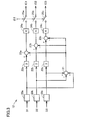
- FIG. 3 is a block diagram showing the configuration of the current command unit 12.
- the current command unit 12 includes signal generators 20a to 20c, an adder 21, multipliers 22a to 22c, 24a to 24c, subtractors 23a to 23c, and switches 25a to 25c.
- the signal generators 20a to 20b receive the output signals D1 to D3 of the code determination unit 11, respectively.
- the signal generator 20a outputs “1” when the signal D1 is at “H” level, and outputs “0” when the signal D1 is at “L” level.
- the signal generator 20b outputs “1” when the signal D2 is at “H” level, and outputs “0” when the signal D2 is at “L” level.
- the signal generator 20c outputs “1” when the signal D3 is at “H” level, and outputs “0” when the signal D3 is at “L” level.
- the adder 21 adds the output values of the signal generators 20a to 20c.
- the multipliers 22a to 22c multiply the output values of the signal generators 20a to 20c by “3”, respectively.
- the subtractors 23a to 23c subtract the output value of the adder 21 from the output values of the multipliers 22a to 22c, respectively.
- the multipliers 24a to 24c multiply the output values of the subtractors 23a to 23c by “K”, respectively. K is a positive real number.
- the output values of the multipliers 24a to 24c become current command values IC1 to IC3, respectively.
- the one terminals of the switches 25a to 25c receive the output values of the multipliers 24a to 24c, respectively, and the other terminals thereof are connected to the converter control unit 14.
- the switches 25a to 25c are turned off when the abnormality detection signal ⁇ 2 is at the “L” level of the inactivation level, and are turned on when the abnormality detection signal ⁇ 2 is at the “H” level of the activation level.
- any two of the signals D1 to D3 are set to the “H” level.
- One signal is set to the “L” level, or any two signals D1 to D3 are set to the “L” level, and the other signal is set to the “H” level.
- the current command values IC1 and IC2 are set to “K” and the current command value IC3 is set to "-2K".
- the polarities of the current command values IC1 to IC3 are the same as the polarities of the currents Is1 to Is3, respectively, and the sum of the current command values IC1 to IC3 is 0.
- any two of the signals D1 to D3 (for example, D1 and D2) are set to the “L” level and the other signal (D3 in this case) is set to the “H” level
- three signals The output value of any two of the signal generators 20a to 20c (in this case, 20a and 20b) is “0”, and the output value of the other signal generator (in this case, 20c) is “ 1 ”and the output value of the adder 21 becomes“ 1 ”.
- the output value of any two of the three multipliers 22a to 22c (22a, 22b in this case) is “0”, and the output value of the other multiplier (22c in this case) is “3”.
- any two of the three subtractors 23a to 23c is “ ⁇ 1”, and the output value of the other subtractor (in this case, 23c) is “ 2 ”.
- the current command values ICA1 and ICA2 are set to “ ⁇ K” and the current command The value ICA3 is set to “2K”.
- the polarities of the current command values ICA1 to ICA3 are the same as the polarities of the currents Is1 to Is3, respectively, and the sum of the current command values ICA1 to ICA3 is zero.
- both the signals D1 to D3 are set to the “L” level.
- the output values of the signal generators 20a to 20c, the adder 21, the multipliers 22a to 22c, 24a to 24c, and the subtractors 23a to 23c are all “0”, and the current command values IC1 to IC3 are all 0. It becomes.
- the converter control unit 14 determines that the switches 1a to 1c have extinguished when the current command values IC1 to IC3 all become zero.
- the abnormality detector 3 sets the abnormality detection signal ⁇ 3 to the “L” level of the inactivation level.
- an on command signal is given from the switch control unit 10 to the switches 1a to 1c to turn on the switches 1a to 1c, and the commercial AC power supply 51 turns on the switches 1a to 1c.
- the three-phase alternating current is supplied to the load 52 via the, and the load 52 is operated. At this time, power converters 2a to 2c are set to a standby state.
- the abnormality detector 3 sets the abnormality detection signal ⁇ 3 to the activation level “H”.
- abnormality detection signal ⁇ 3 is set to “H” level, an off command signal is given from switch control unit 10 to switches 1a to 1c, and power converters 2a to 2c are driven by DC power of DC power supply 53, and DC Currents Io1 to Io3 are output.
- the polarities of the direct currents Io1 to Io3 are made the same as the polarities of the currents Is1 to Is3 flowing in the switches 1a to 1c, respectively.
- the sum of the values of the direct currents Io1 to Io3 is set to zero.
- At least a part of the load currents IL1 to IL3 is replaced with the direct currents Io1 to Io3, the currents Is1 to Is3 flowing through the switches 1a to 1c are reduced, and the switches 1a to 1c are quickly extinguished and turned off.
- the switches 1a to 1c are turned off, a three-phase alternating current is supplied from the power converters 4a to 4c to the load 52, and the operation of the load 52 is continued.
- the current detectors 4a to 4c are provided on the commercial AC power supply 51 side of the switches 1a to 1c, and the currents Is1 to Is3 flowing from the commercial AC power supply 51 to the switches 1a to 1c are supplied to the current detectors 4a to 4c. Detected by 4c.
- the same result can be obtained even if the current detectors 4a to 4c are provided on the load 52 side of the switches 1a to 1c and the currents Is1 to Is3 flowing from the switches 1a to 1c to the load 52 are detected by the current detectors 4a to 4c. .
- the DC power supply 53 for driving the power converters 2a to 2c is provided, but a battery (power storage device) may be provided as the DC power supply 53.
- the control circuit 6 controls the power converters 2a to 2c so that the battery terminal voltage becomes the target battery voltage.
- the power converters 2a to 2c are controlled by the control circuit 6 and convert the three-phase AC power supplied from the commercial AC power supply 51 via the switches 1a to 1c into DC power and store it in the battery.
- FIG. 4 is a block diagram showing a configuration of control circuit 6A included in the uninterruptible power supply according to Embodiment 2 of the present invention, and is a diagram compared with FIG. The entire configuration of the uninterruptible power supply is as shown in FIG.
- the output signals ⁇ 4a to ⁇ 4c of the current detectors 4a to 4c, the output signals ⁇ 5a to 5c of the current detectors 5a to 5c, the control circuit 6A and the power The converters 2a to 2c are controlled.
- the control circuit 6A gives an on command signal to the switches 1a to 1c to turn it on.
- a three-phase AC current is supplied from the commercial AC power supply 51 to the load 52 via the switches 1a to 1c, and the load 52 is operated.
- the control circuit 6A controls the power converters 2a to 2 so that the currents Is1 to Is3 flowing through the switches 1a to 1c become DC currents IDC1 to IDC3, respectively.
- the switches 1a to 1c are extinguished by controlling the output currents Io1 to Io3 of 2c.
- the polarities of the DC currents IDC1 to IDC3 are opposite to the polarities of the currents Is1 to Is3 flowing through the switches 1a to 1c, respectively, and the sum of the values of the DC currents IDC1 to IDC3 is set to zero.
- the absolute values of the direct currents IDC1 to IDC3 are set to values sufficiently smaller than the amplitudes of the three-phase alternating currents Is1 to Is3 flowing through the switches 1a to 1c.
- control circuit 6A supplies a three-phase alternating current to the load 52 from the power converters 2a to 2c to continue the operation of the load 52.
- control circuit 6A is different from the control circuit 6 of FIG. 2 in that the current command unit 12, the voltage command unit 13, and the converter control unit 14 are switch current command units 30 and 31, a switch current control unit 32, And the converter current control unit 33 is replaced.
- the switch current command unit 30 is activated when the abnormality detection signal ⁇ 3 is set to the activation level “H” level, and the DC currents IDC1 to IDC3 having the opposite polarity to the currents Is1 to Is3 flowing through the switches 1a to 1c.
- Current command values ICA1 to ICA3 that are target values of the output currents Io1 to Io3 of the power converters 2a to 2c are generated so that the current flows through the switches 1a to 1c. While the currents Is1 to Is3 flowing through the switches 1a to 1c change toward the direct currents IDC1 to IDC3, respectively, the current becomes 0A, and the switches 1a to 1c are rapidly extinguished. At this time, the sum of the current command values ICA1 to ICA3 is set to 0, and the sum of the values of the DC currents IDC1 to IDC3 is set to 0.
- the switch current command unit 31 is connected to the power converters 2a to 2c so that currents Io1 to Io3 that change in a sinusoidal shape at the same frequency as the AC voltages Vi1 to Vi3 supplied from the commercial AC power supply 51 flow to the switches 1a to 1c.
- Current command values ICB1 to ICB3 that are target values of the output currents Io1 to Io3 are generated.
- the current command values ICA1 to ICA3 and ICB1 to ICB3 are given to the switch current control unit 32.
- the switch current control unit 32 operates based on the abnormality detection signal ⁇ 3, the current command values ICA1 to ICA3, and the output signals ⁇ 4a to ⁇ 4c of the current detectors 4a to 4c.
- the switch current control unit 32 determines the deviation ICB1- between the current command values ICB1 to ICB3 and the detection values Is1 to Is3 of the current detectors 4a to 4c.
- Current command values ICC1 to ICC3 at levels according to Is1, ICB2-Is2, and ICB3-Is3 are output.
- the output currents Io1 to Io3 of the power converters 2a to 2c are controlled so that the detection values Is1 to Is3 of the current detectors 4a to 4c coincide with the current command values ICB1 to ICB3, and the power converters 2a to 2c are controlled. Is put into standby.
- the switch current control unit 32 detects the deviation ICA1 between the current command values ICA1 to ICA3 and the detection values Is1 to Is3 of the current detectors 4a to 4c.
- the output currents Io1 to Io3 of the power converters 2a to 2c are controlled so that the detection values Is1 to Is3 of the current detectors 4a to 4c coincide with the current command values ICA1 to ICA3, and the switches 1a to 1c are turned off. Arced.
- the switch current control unit 32 extinguishes the switches 1a to 1c, and thereafter, deviations ICB1-Is1, ICB2-Is2, and ICB3- between the current command values ICB1 to ICB3 and the detected values Is1 to Is3 of the current detectors 4a to 4c.
- the current command values ICC1 to ICC3 at a level corresponding to Is3 are output.
- the output currents Io1 to Io3 of the power converters 2a to 2c are controlled so that the detection values Is1 to Is3 of the current detectors 4a to 4c coincide with the current command values ICB1 to ICB3, and the operation of the load 52 is continued. Is done.
- the converter current control unit 33 generates voltage command values VC1 at levels corresponding to deviations ICC1-Io1, ICC2-Io2, ICC3-Io3 between the current command values ICC1 to ICC3 and the detected values Io1 to Io3 of the current detectors 5a to 5c. ⁇ VC3 is output.
- the PWM signal generator 15 generates PWM signals ⁇ 6a to ⁇ 6c according to the voltage command values VC1 to VC3, respectively, and supplies the generated PWM signals ⁇ 6a to ⁇ 6c to the power converters 2a to 2c, respectively.
- FIG. 5 is a block diagram showing the configuration of the switch current command unit 30 and is a diagram to be compared with FIG.
- switch current command unit 30 is different from current command unit 12 in FIG. 3 in that inverters 40a to 40c are added and multipliers 24a to 24c are replaced with multipliers 41a to 41c. Is a point.
- the inverters 40a to 40c receive the output signals D1 to D3 from the sign determination unit 11, respectively, and output inverted signals / D1 to / D3 of the signals D1 to D3.
- the multipliers 41a to 41c multiply the output values of the subtracters 23a to 23c by “M”, respectively. M is a positive real number.
- the output values of the multipliers 40a to 40c are current command values ICA1 to ICA3, respectively.
- the one terminals of the switches 25a to 25c receive the output values of the multipliers 40a to 40c, respectively, and the other terminals are connected to the switch current control unit 32.
- the switches 25a to 25c are turned off when the abnormality detection signal ⁇ 3 is at the “L” level of the inactivation level, and are turned on when the abnormality detection signal ⁇ 3 is at the “H” level of the activation level.
- any two of the signals D1 to D3 are set to the “H” level, and the other signal Is set to the “L” level, or any two of the signals D1 to D3 are set to the “L” level, and the other signal is set to the “H” level.
- any two of the signals D1 to D3 (for example, D1 and D2) are set to the “H” level and the other signal (D3 in this case) is set to the “L” level
- the signal / Any two of D1 to / D3 (in this case, / D1, / D2) are set to the “L” level
- the other signal (in this case, / D3) is set to the “H” level.
- the output value of any two of the three signal generators 20a to 20c (in this case, 20a and 20b) is “0”, and another signal generator (in this case, 20c). ) Becomes “1”, and the output value of the adder 21 becomes “1”.
- the output value of any two of the three multipliers 22a to 22c (22a, 22b in this case) is “0”, and the output value of the other multiplier (20c in this case) is “3”.
- any two of the three subtractors 23a to 23c is “ ⁇ 1”, and the output value of the other subtractor (in this case, 23c) is “ 2 ”.
- the output value of any two of the three multipliers 24a to 24c is “ ⁇ M”, and the output value of the other multiplier (in this case, 24c) is “ ⁇ M”. 2M ".
- any two of the three current command values ICA1 to ICA3 are “ ⁇ M”, and the other current command value (in this case, ICA3) is “2M”.
- the current command values ICA1 and ICA2 are set to “ ⁇ M”, and the current command The value ICA3 is set to “2M”.
- the polarities of the current command values ICA1 to ICA3 are opposite to the polarities of the currents Is1 to Is3, respectively, and the sum of the current command values ICA1 to ICA3 is zero.
- any two of the signals D1 to D3 (for example, D1 and D2) are set to the “L” level and the other signal (D3 in this case) is set to the “H” level
- the signal / Any two of the signals D1 to / D3 (in this case, / D1, / D2) are set to the “H” level
- the other signal (in this case, / D3) is set to the “L” level.
- the output value of any two of the three signal generators 20a to 20c (in this case, 20a and 20b) is “1”, and the other signal generator (in this case, 20c) ) Becomes “0”, and the output value of the adder 21 becomes “2”.
- the output value of any two of the three multipliers 22a to 22c (22a, 22b in this case) is “3”, and the output value of the other multiplier (22c in this case) is “0”.
- any two of the three subtractors 23a to 23c is “1”, and the output value of the other subtractor (in this case, 23c) is “ ⁇ 2 ”.
- the output value of any two of the three multipliers 24a to 24c (24a and 24b in this case) is “M”, and the output value of the other multiplier (24c in this case) is “ ⁇ 2M ". Therefore, any two of the three current command values ICA1 to ICA3 (in this case, ICA1 and ICA2) are “M”, and the other current command value (in this case, ICA3) is “ ⁇ 2M.
- the current command values ICA1 and ICA2 are set to “M” and the current command value ICA3 is set to "-2M”.
- the polarities of the current command values ICA1 to ICA3 are opposite to the polarities of the currents Is1 to Is3, respectively, and the sum of the current command values ICA1 to ICA3 is zero.
- both the signals / D1 to / D3 are set to the “H” level.
- the output values of the signal generators 20a to 20c are both “1”
- the output values of the adder 21 and the multipliers 22a to 22c are both “3”
- the subtractors 23a to 23c and the multipliers 41a to 41a Both of the output values of 41c are “0”
- the current command values ICA1 to ICA3 are all 0.
- the switch current control unit 32 determines that the switches 1a to 1c are extinguished when the current command values ICA1 to ICA3 are all zero.
- the abnormality detector 3 sets the abnormality detection signal ⁇ 3 to the “L” level of the inactivation level.
- an on command signal is given from the switch control unit 10 to the switches 1a to 1c to turn on the switches 1a to 1c, and the commercial AC power supply 51 turns on the switches 1a to 1c.
- the three-phase alternating current is supplied to the load 52 via the, and the load 52 is operated. At this time, power converters 2a to 2c are set to a standby state.
- the abnormality detector 3 sets the abnormality detection signal ⁇ 3 to the activation level “H”.
- the switch controller 10 gives an OFF command signal to the switches 1a to 1c, and a DC current having a reverse polarity to the currents Is1 to Is3 flowing through the switches 1a to 1c.
- the power converters 2a to 2c are controlled so that the IDC1 to IDC3 flow to the switches 1a to 1c.
- the power converters 2a to 2c are driven by the DC power of the DC power supply 53 and output DC currents Io1 to Io3.
- the sum of the DC currents IDC1 to IDC3 is set to zero.
- the values of the currents Is1 to Is3 flowing through the switches 1a to 1c are decreased, and the switches 1a to 1c are quickly Is extinguished and turned off.
- the switches 1a to 1c are turned off, a three-phase alternating current is supplied from the power converters 4a to 4c to the load 52, and the operation of the load 52 is continued.
- TI1 to TI3 input terminal TO1 to TO3 output terminal, 1a to 1c, 25a to 25c switch, 2a to 2c power converter, 3 abnormality detector, 4a to 4c, 5a to 5c current detector, 6, 6A control circuit, 10 switch control unit, 11 sign determination unit, 12 current command unit, 13 voltage command unit, 14 converter control unit, 15 PWM signal generation unit, 20a-20c signal generator, 21 adder, 22a-22c, 24a-24c , 41a to 41c multiplier, 23a to 23c subtractor, 30, 31 switch current command unit, 32 switch current control unit, 33 converter current control unit, 40a to 40c inverter, 51 commercial AC power supply, 52 load, 53 DC Power supply.
Landscapes
- Business, Economics & Management (AREA)
- Emergency Management (AREA)
- Engineering & Computer Science (AREA)
- Power Engineering (AREA)
- Inverter Devices (AREA)
- Rectifiers (AREA)
- Stand-By Power Supply Arrangements (AREA)
Abstract
Description
図1は、この発明の実施の形態1による無停電電源装置の全体構成を示す回路ブロック図である。図1において、この無停電電源装置は、常時商用給電方式の無停電電源装置であって、入力端子TI1~TI3、出力端子TO1~TO3、スイッチ1a~1c、電力変換器2a~2c、異常検出器3、電流検出器4a~4c,5a~5c、および制御回路6を備える。
図4は、この発明の実施の形態2による無停電電源装置に含まれる制御回路6Aの構成を示すブロック図であって、図2と対比される図である。無停電電源装置の全体構成は図1で示した通りである。
Claims (6)
- 常時商用給電方式の無停電電源装置であって、
負荷に三相交流電流を供給するための第1~第3の出力端子と、
それらの第1の端子が商用交流電源からの三相交流電圧を受け、それらの第2の端子がそれぞれ前記第1~第3の出力端子に接続される自己消弧能力を持たない第1~第3のスイッチと、
それぞれ前記第1~第3の出力端子に接続され、直流電源から供給される直流電力によって駆動される第1~第3の電力変換器と、
前記商用交流電源からの三相交流電圧が異常になったことを検出する異常検出器と、
それぞれ前記第1~第3のスイッチに流れる電流の瞬時値を検出する第1~第3の電流検出器と、
前記異常検出器および前記第1~第3の電流検出器の検出結果に基づいて前記第1~第3のスイッチおよび前記第1~第3の電力変換器を制御する制御回路とを備え、
前記商用交流電源からの三相交流電圧が正常である場合は、前記第1~第3のスイッチがオン状態にされ、前記商用交流電源から前記第1~第3のスイッチを介して前記負荷に三相交流電流が供給され、
前記商用交流電源からの三相交流電圧が異常になった場合は、前記制御回路から前記第1~第3のスイッチにオフ指令信号が与えられるとともに、前記第1~第3の電力変換器からそれぞれ第1~第3の直流電流が出力されて前記第1~第3のスイッチが消弧され、さらに、前記第1~第3の電力変換器から前記負荷に三相交流電流が供給されて前記負荷の運転が継続され、
前記第1~第3のスイッチの各々の第1の端子から第2の端子に向かって流れる電流の極性を正極性とし、前記第1~第3の電力変換器からそれぞれ前記第1~第3の出力端子に向かって流れる電流の極性を正極性とすると、前記第1~第3の直流電流の極性はそれぞれ前記第1~第3のスイッチに流れている電流の極性と同じであり、前記第1~第3の直流電流の値の和は0にされている、無停電電源装置。 - 前記制御回路は、
前記第1~第3の電流検出器の検出結果に基づいて前記第1~第3のスイッチに流れる電流の各々の極性を判定し、その判定結果に基づいて前記第1~第3の直流電流の極性をそれぞれ前記第1~第3のスイッチに流れる電流の極性と同じ極性に設定し、
前記第1および第2のスイッチに流れる電流の極性が同じである場合は、前記第1および第2の直流電流の各々の値の絶対値を第1の値に設定し、前記第3の直流電流の値の絶対値を前記第1の値の2倍の第2の値に設定し、
前記第2および第3のスイッチに流れる電流の極性が同じである場合は、前記第2および第3の直流電流の各々の値の絶対値を前記第1の値に設定し、前記第1の直流電流の値の絶対値を前記第2の値に設定し、
前記第3および第1のスイッチに流れる電流の極性が同じである場合は、前記第3および第1の直流電流の各々の値の絶対値を前記第1の値に設定し、前記第2の直流電流の値の絶対値を前記第2の値に設定し、
前記第1~第3の電力変換器は、前記制御回路によって設定された前記第1~第3の直流電流を出力する、請求項1に記載の無停電電源装置。 - 前記直流電源は、直流電力を蓄える電力貯蔵装置であり、
前記第1~第3の電力変換器は、
前記商用交流電源からの三相交流電圧が正常である場合は、前記商用交流電源から前記第1~第3のスイッチを介して供給される三相交流電力を直流電力に変換して前記電力貯蔵装置に蓄え、
前記商用交流電源からの三相交流電圧が異常になった場合は、前記電力貯蔵装置の直流電力によって駆動されて、前記第1~第3の直流電流および三相交流電流を出力する、請求項1に記載の無停電電源装置。 - 常時商用給電方式の無停電電源装置であって、
負荷に三相交流電流を供給するための第1~第3の出力端子と、
それらの第1の端子が商用交流電源からの三相交流電圧を受け、それらの第2の端子がそれぞれ前記第1~第3の出力端子に接続される自己消弧能力を持たない第1~第3のスイッチと、
それぞれ前記第1~第3の出力端子に接続され、直流電源から供給される直流電力によって駆動される第1~第3の電力変換器と、
前記商用交流電源からの三相交流電圧が異常になったことを検出する異常検出器と、
それぞれ前記第1~第3のスイッチに流れる電流の瞬時値を検出する第1~第3の電流検出器と、
前記異常検出器および前記第1~第3の電流検出器の検出結果に基づいて前記第1~第3のスイッチおよび前記第1~第3の電力変換器を制御する制御回路とを備え、
前記商用交流電源からの三相交流電圧が正常である場合は、前記第1~第3のスイッチがオン状態にされ、前記商用交流電源から前記第1~第3のスイッチを介して前記負荷に三相交流電流が供給され、
前記商用交流電源からの三相交流電圧が異常になった場合は、前記制御回路から前記第1~第3のスイッチにオフ指令信号が与えられるとともに、前記第1~第3のスイッチに流れる電流がそれぞれ第1~第3の直流電流になるように前記第1~第3の電力変換器の出力電流が制御されて前記第1~第3のスイッチが消弧され、さらに、前記第1~第3の電力変換器から前記負荷に三相交流電流が供給されて前記負荷の運転が継続され、
前記第1~第3のスイッチの各々の第1の端子から第2の端子に向かって流れる電流の極性を正極性とすると、前記第1~第3の直流電流の極性はそれぞれ前記第1~第3のスイッチに流れている電流の極性と逆であり、前記第1~第3の直流電流の値の和は0にされている、無停電電源装置。 - 前記制御回路は、
前記第1~第3の電流検出器の検出結果に基づいて前記第1~第3のスイッチに流れる電流の各々の極性を判定し、その判定結果に基づいて前記第1~第3の直流電流の極性をそれぞれ前記第1~第3のスイッチに流れる電流の極性と逆の極性に設定し、
前記第1および第2のスイッチに流れる電流の極性が同じである場合は、前記第1および第2の直流電流の各々の値の絶対値を第1の値に設定し、前記第3の直流電流の値の絶対値を前記第1の値の2倍の第2の値に設定し、
前記第2および第3のスイッチに流れる電流の極性が同じである場合は、前記第2および第3の直流電流の各々の値の絶対値を前記第1の値に設定し、前記第1の直流電流の値の絶対値を前記第2の値に設定し、
前記第3および第1のスイッチに流れる電流の極性が同じである場合は、前記第3および第1の直流電流の各々の値の絶対値を前記第1の値に設定し、前記第2の直流電流の値の絶対値を前記第2の値に設定し、
前記第1~第3の電力変換器は、前記制御回路によって設定された前記第1~第3の直流電流を出力する、請求項4に記載の無停電電源装置。 - 前記直流電源は、直流電力を蓄える電力貯蔵装置であり、
前記第1~第3の電力変換器は、
前記商用交流電源からの三相交流電圧が正常である場合は、前記商用交流電源から前記第1~第3のスイッチを介して供給される三相交流電力を直流電力に変換して前記電力貯蔵装置に蓄え、
前記商用交流電源からの三相交流電圧が異常になった場合は、前記電力貯蔵装置の直流電力によって駆動されて、前記第1~第3の直流電流および三相交流電流を出力する、請求項4に記載の無停電電源装置。
Priority Applications (5)
| Application Number | Priority Date | Filing Date | Title |
|---|---|---|---|
| JP2017553513A JP6538874B2 (ja) | 2015-12-01 | 2015-12-01 | 無停電電源装置 |
| US15/770,928 US10305322B2 (en) | 2015-12-01 | 2015-12-01 | Uninterruptible power supply device |
| CN201580085049.4A CN108370174B (zh) | 2015-12-01 | 2015-12-01 | 不间断电源装置 |
| KR1020187017873A KR102046275B1 (ko) | 2015-12-01 | 2015-12-01 | 무정전 전원 장치 |
| PCT/JP2015/083682 WO2017094093A1 (ja) | 2015-12-01 | 2015-12-01 | 無停電電源装置 |
Applications Claiming Priority (1)
| Application Number | Priority Date | Filing Date | Title |
|---|---|---|---|
| PCT/JP2015/083682 WO2017094093A1 (ja) | 2015-12-01 | 2015-12-01 | 無停電電源装置 |
Publications (2)
| Publication Number | Publication Date |
|---|---|
| WO2017094093A1 true WO2017094093A1 (ja) | 2017-06-08 |
| WO2017094093A9 WO2017094093A9 (ja) | 2018-04-12 |
Family
ID=58796566
Family Applications (1)
| Application Number | Title | Priority Date | Filing Date |
|---|---|---|---|
| PCT/JP2015/083682 Ceased WO2017094093A1 (ja) | 2015-12-01 | 2015-12-01 | 無停電電源装置 |
Country Status (5)
| Country | Link |
|---|---|
| US (1) | US10305322B2 (ja) |
| JP (1) | JP6538874B2 (ja) |
| KR (1) | KR102046275B1 (ja) |
| CN (1) | CN108370174B (ja) |
| WO (1) | WO2017094093A1 (ja) |
Cited By (2)
| Publication number | Priority date | Publication date | Assignee | Title |
|---|---|---|---|---|
| JPWO2020017164A1 (ja) * | 2018-07-19 | 2020-12-17 | 富士電機株式会社 | 無停電電源装置 |
| CN112768274A (zh) * | 2021-01-15 | 2021-05-07 | 常熟开关制造有限公司(原常熟开关厂) | 主动灭弧方法、装置及断路器、自动转换开关 |
Families Citing this family (3)
| Publication number | Priority date | Publication date | Assignee | Title |
|---|---|---|---|---|
| ES2765652T3 (es) * | 2016-08-08 | 2020-06-10 | Abb Schweiz Ag | Instalación energética con SAI |
| KR102620030B1 (ko) * | 2019-06-17 | 2023-12-29 | 도시바 미쓰비시덴키 산교시스템 가부시키가이샤 | 전원 장치 및 교류 전원의 이상 검출 방법 |
| CN114069817A (zh) * | 2020-07-31 | 2022-02-18 | 华为数字能源技术有限公司 | 一种不间断电源、通断控制模块、控制方法及系统 |
Citations (4)
| Publication number | Priority date | Publication date | Assignee | Title |
|---|---|---|---|---|
| JP2003087999A (ja) * | 2001-06-26 | 2003-03-20 | Sanyo Denki Co Ltd | 無停電電源装置及び無停電電源装置の交流スイッチ遮断方法 |
| JP2005295665A (ja) * | 2004-03-31 | 2005-10-20 | Sanken Electric Co Ltd | 電源装置 |
| JP2006121892A (ja) * | 2004-09-27 | 2006-05-11 | Fuji Electric Systems Co Ltd | 無停電電源装置 |
| JP2006187089A (ja) * | 2004-12-27 | 2006-07-13 | Fuji Electric Systems Co Ltd | 無停電電源装置及び無停電電源装置の制御方法 |
Family Cites Families (13)
| Publication number | Priority date | Publication date | Assignee | Title |
|---|---|---|---|---|
| JPH08205555A (ja) * | 1995-01-25 | 1996-08-09 | Toshiba Corp | 電力系統と連携する電力変換器の制御装置 |
| JP3406835B2 (ja) | 1998-05-21 | 2003-05-19 | 東京電力株式会社 | 分散型電源システム |
| EP1276202B1 (en) * | 2001-06-26 | 2008-01-09 | Sanyo Denki Co., Ltd. | Uninterruptible power supply and method of turning off AC switch for uninterruptible power supply |
| JP3819805B2 (ja) | 2002-05-16 | 2006-09-13 | 三菱電機株式会社 | 系統連系電力変換装置 |
| JP3929449B2 (ja) * | 2004-03-29 | 2007-06-13 | 日新電機株式会社 | 無停電電源装置、及び停電補償システム |
| EP1965483B1 (de) * | 2007-02-27 | 2015-07-08 | SMA Solar Technology AG | Schaltung zur Verbindung einer Energieerzeugungsanlage mit dem Stromnetz |
| JP4814264B2 (ja) * | 2008-01-25 | 2011-11-16 | 三菱電機株式会社 | 無停電電源装置 |
| JP5561071B2 (ja) * | 2010-09-29 | 2014-07-30 | サンケン電気株式会社 | 無停電電源装置 |
| CN201887537U (zh) * | 2010-11-24 | 2011-06-29 | 方彧 | 一种消弧柜 |
| CN102075008A (zh) * | 2011-01-21 | 2011-05-25 | 大连理工大学 | 一种机电混合式电压瞬低补偿装置 |
| TWI443935B (zh) * | 2011-07-13 | 2014-07-01 | Delta Electronics Inc | 不斷電電源供應器 |
| WO2014011706A1 (en) * | 2012-07-09 | 2014-01-16 | Inertech Ip Llc | Transformerless multi-level medium-voltage uninterruptible power supply (ups) systems and methods |
| KR20150121797A (ko) * | 2014-04-22 | 2015-10-30 | (주)그린파워 | 정전보상기능을 갖는 에너지저장시스템 |
-
2015
- 2015-12-01 JP JP2017553513A patent/JP6538874B2/ja active Active
- 2015-12-01 CN CN201580085049.4A patent/CN108370174B/zh active Active
- 2015-12-01 US US15/770,928 patent/US10305322B2/en active Active
- 2015-12-01 WO PCT/JP2015/083682 patent/WO2017094093A1/ja not_active Ceased
- 2015-12-01 KR KR1020187017873A patent/KR102046275B1/ko active Active
Patent Citations (4)
| Publication number | Priority date | Publication date | Assignee | Title |
|---|---|---|---|---|
| JP2003087999A (ja) * | 2001-06-26 | 2003-03-20 | Sanyo Denki Co Ltd | 無停電電源装置及び無停電電源装置の交流スイッチ遮断方法 |
| JP2005295665A (ja) * | 2004-03-31 | 2005-10-20 | Sanken Electric Co Ltd | 電源装置 |
| JP2006121892A (ja) * | 2004-09-27 | 2006-05-11 | Fuji Electric Systems Co Ltd | 無停電電源装置 |
| JP2006187089A (ja) * | 2004-12-27 | 2006-07-13 | Fuji Electric Systems Co Ltd | 無停電電源装置及び無停電電源装置の制御方法 |
Cited By (3)
| Publication number | Priority date | Publication date | Assignee | Title |
|---|---|---|---|---|
| JPWO2020017164A1 (ja) * | 2018-07-19 | 2020-12-17 | 富士電機株式会社 | 無停電電源装置 |
| CN112768274A (zh) * | 2021-01-15 | 2021-05-07 | 常熟开关制造有限公司(原常熟开关厂) | 主动灭弧方法、装置及断路器、自动转换开关 |
| CN112768274B (zh) * | 2021-01-15 | 2021-10-01 | 常熟开关制造有限公司(原常熟开关厂) | 主动灭弧方法、装置及断路器、自动转换开关 |
Also Published As
| Publication number | Publication date |
|---|---|
| KR102046275B1 (ko) | 2019-11-18 |
| CN108370174A (zh) | 2018-08-03 |
| US10305322B2 (en) | 2019-05-28 |
| JPWO2017094093A1 (ja) | 2018-09-13 |
| CN108370174B (zh) | 2021-06-04 |
| KR20180085000A (ko) | 2018-07-25 |
| WO2017094093A9 (ja) | 2018-04-12 |
| US20180309319A1 (en) | 2018-10-25 |
| JP6538874B2 (ja) | 2019-07-03 |
Similar Documents
| Publication | Publication Date | Title |
|---|---|---|
| JP6392892B2 (ja) | 無停電電源装置 | |
| US10615636B2 (en) | Uninterruptible power supply | |
| WO2017094093A1 (ja) | 無停電電源装置 | |
| JPWO2017094179A1 (ja) | 電力変換システム | |
| KR102343983B1 (ko) | 전원 장치 | |
| TWI660566B (zh) | 電力變換裝置 | |
| JPWO2015132960A1 (ja) | インバータ試験装置 | |
| JP6243553B2 (ja) | 無停電電源システム | |
| TWI657648B (zh) | 電源裝置及使用該電源裝置之電源系統 | |
| KR20220061224A (ko) | 무정전 전원 장치 | |
| US11336114B2 (en) | Uninterruptible power supply apparatus | |
| JP2012080738A (ja) | 電源装置 | |
| TWI625036B (zh) | 電力變換裝置 | |
| JP6172231B2 (ja) | 電力変換装置 | |
| JP2019030070A (ja) | マルチレベルインバータの制御装置および制御方法 | |
| JP4893113B2 (ja) | 整流回路の制御装置 | |
| JP4448294B2 (ja) | 電力変換装置 | |
| WO2018185811A1 (ja) | 電力変換装置 | |
| JP2020018054A (ja) | 無停電電源装置 |
Legal Events
| Date | Code | Title | Description |
|---|---|---|---|
| 121 | Ep: the epo has been informed by wipo that ep was designated in this application |
Ref document number: 15909723 Country of ref document: EP Kind code of ref document: A1 |
|
| ENP | Entry into the national phase |
Ref document number: 2017553513 Country of ref document: JP Kind code of ref document: A |
|
| WWE | Wipo information: entry into national phase |
Ref document number: 15770928 Country of ref document: US |
|
| NENP | Non-entry into the national phase |
Ref country code: DE |
|
| ENP | Entry into the national phase |
Ref document number: 20187017873 Country of ref document: KR Kind code of ref document: A |
|
| WWE | Wipo information: entry into national phase |
Ref document number: 1020187017873 Country of ref document: KR |
|
| 122 | Ep: pct application non-entry in european phase |
Ref document number: 15909723 Country of ref document: EP Kind code of ref document: A1 |