WO2017090552A1 - 内燃機関用回転電機およびその電極 - Google Patents
内燃機関用回転電機およびその電極 Download PDFInfo
- Publication number
- WO2017090552A1 WO2017090552A1 PCT/JP2016/084429 JP2016084429W WO2017090552A1 WO 2017090552 A1 WO2017090552 A1 WO 2017090552A1 JP 2016084429 W JP2016084429 W JP 2016084429W WO 2017090552 A1 WO2017090552 A1 WO 2017090552A1
- Authority
- WO
- WIPO (PCT)
- Prior art keywords
- terminal
- electrode
- electrical machine
- rotating electrical
- internal combustion
- Prior art date
- Legal status (The legal status is an assumption and is not a legal conclusion. Google has not performed a legal analysis and makes no representation as to the accuracy of the status listed.)
- Ceased
Links
Images


Classifications
-
- H—ELECTRICITY
- H01—ELECTRIC ELEMENTS
- H01R—ELECTRICALLY-CONDUCTIVE CONNECTIONS; STRUCTURAL ASSOCIATIONS OF A PLURALITY OF MUTUALLY-INSULATED ELECTRICAL CONNECTING ELEMENTS; COUPLING DEVICES; CURRENT COLLECTORS
- H01R4/00—Electrically-conductive connections between two or more conductive members in direct contact, i.e. touching one another; Means for effecting or maintaining such contact; Electrically-conductive connections having two or more spaced connecting locations for conductors and using contact members penetrating insulation
- H01R4/02—Soldered or welded connections
-
- H—ELECTRICITY
- H01—ELECTRIC ELEMENTS
- H01R—ELECTRICALLY-CONDUCTIVE CONNECTIONS; STRUCTURAL ASSOCIATIONS OF A PLURALITY OF MUTUALLY-INSULATED ELECTRICAL CONNECTING ELEMENTS; COUPLING DEVICES; CURRENT COLLECTORS
- H01R4/00—Electrically-conductive connections between two or more conductive members in direct contact, i.e. touching one another; Means for effecting or maintaining such contact; Electrically-conductive connections having two or more spaced connecting locations for conductors and using contact members penetrating insulation
- H01R4/58—Electrically-conductive connections between two or more conductive members in direct contact, i.e. touching one another; Means for effecting or maintaining such contact; Electrically-conductive connections having two or more spaced connecting locations for conductors and using contact members penetrating insulation characterised by the form or material of the contacting members
- H01R4/62—Connections between conductors of different materials; Connections between or with aluminium or steel-core aluminium conductors
-
- H—ELECTRICITY
- H02—GENERATION; CONVERSION OR DISTRIBUTION OF ELECTRIC POWER
- H02K—DYNAMO-ELECTRIC MACHINES
- H02K3/00—Details of windings
- H02K3/02—Windings characterised by the conductor material
-
- H—ELECTRICITY
- H02—GENERATION; CONVERSION OR DISTRIBUTION OF ELECTRIC POWER
- H02K—DYNAMO-ELECTRIC MACHINES
- H02K3/00—Details of windings
- H02K3/04—Windings characterised by the conductor shape, form or construction, e.g. with bar conductors
-
- H—ELECTRICITY
- H02—GENERATION; CONVERSION OR DISTRIBUTION OF ELECTRIC POWER
- H02K—DYNAMO-ELECTRIC MACHINES
- H02K3/00—Details of windings
- H02K3/32—Windings characterised by the shape, form or construction of the insulation
- H02K3/38—Windings characterised by the shape, form or construction of the insulation around winding heads, equalising connectors, or connections thereto
Definitions
- the disclosure in this specification relates to a rotating electrical machine connected to an internal combustion engine and its electrodes.
- Patent Documents 1-4 disclose a rotating electrical machine for an internal combustion engine.
- Patent Document 1 describes a technique for connecting an aluminum wire and an iron electrode.
- the iron electrode has a terminal connected to the electric wire by solder and a terminal connected to the electric wire by welding.
- Tin plating is formed on the surface of the electrode. Tin plating protects the electrodes.
- tin plating is suitable for solder bonding because it has high wettability with solder.
- a protective resin is applied to the surface of the electrode.
- Tin plating may cause delamination inside itself.
- tin plating may peel off due to repeated temperature changes.
- One cause is presumed to be a difference in linear expansion coefficient between the electrode and the protective resin.
- the adhesive surface between the tin plating and the protective resin may peel off.
- the electric wire is welded on the tin plating.
- peeling as described above occurs, corrosion of the electrode or the electric wire in the weld may occur.
- a tin layer or an alloy layer containing tin may be formed in the weld. Such a layer may cause unexpected failures in the weld.
- One disclosed object is to provide an electrode of a rotating electrical machine for an internal combustion engine that can form a highly reliable connection.
- One object disclosed is to provide a rotating electrical machine for an internal combustion engine having a highly reliable connection.
- Another object of the disclosure is to provide a rotating electrical machine for an internal combustion engine in which defects due to tin plating in a connection portion are suppressed.
- the electrode of the rotating electrical machine for the internal combustion engine disclosed herein provides a power line for the stator coil of the rotating electrical machine for the internal combustion engine.
- the electrode includes a terminal connected to the conductor, a base material region where the base material forming the electrode is exposed, and a metal film partially covering the surface of the base material to protect the electrode Is formed.
- the conductor and the terminal are connected in the base material region. For this reason, connection with a conductor is provided in a terminal without a film, suppressing rust or corrosion of an electrode by a film area. Thereby, the malfunction resulting from the membrane
- a rotating electrical machine for an internal combustion engine disclosed herein includes an electrode of the rotating electrical machine for an internal combustion engine described above, a conductor connected to the terminal, and a protective resin that covers the terminal so as to protect the terminal and the conductor.
- the conductor and the terminal are connected in the base material region. For this reason, connection with a conductor is provided in a terminal without a film, suppressing rust or corrosion of an electrode by a film area. Thereby, the malfunction resulting from the membrane
- the base material region and the conductor in the terminal are protected by the protective resin, protection of the base material region and the conductor is provided without a film. As a result, a rotating electrical machine for an internal combustion engine having a highly reliable connection can be provided.
- FIG. 5 is a cross-sectional view taken along line VV in FIG. 4 showing the terminal according to the first embodiment. It is a top view which shows the electrode manufacturing method of 1st Embodiment. It is a top view which shows the electrode manufacturing method of 2nd Embodiment. It is a fragmentary sectional view showing the stator of a 3rd embodiment.
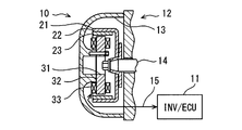
- a rotating electrical machine for an internal combustion engine (hereinafter simply referred to as a rotating electrical machine 10) is also called a generator motor or an AC generator starter.
- the rotating electrical machine 10 is electrically connected to an electric circuit 11 including an inverter circuit (INV) and a control device (ECU).
- the electric circuit 11 provides a three-phase power conversion circuit.
- An example of the use of the rotating electrical machine 10 is a generator motor connected to an internal combustion engine 12 for a vehicle.
- the rotating electrical machine 10 can be used for a motorcycle, for example.
- the electrical circuit 11 provides a rectifier circuit that rectifies the AC power that is output when the rotating electrical machine 10 functions as a generator and supplies power to an electrical load including a battery.
- the electric circuit 11 provides a signal processing circuit that receives a reference position signal supplied from the rotating electrical machine 10.
- the reference position signal is used for ignition timing control and / or fuel injection timing control.
- the electric circuit 11 may provide a controller that performs engine control including ignition timing control and / or fuel injection timing control.
- the electric circuit 11 provides a drive circuit that causes the rotating electrical machine 10 to function as an electric motor.
- the electrical circuit 11 receives from the rotating electrical machine 10 a rotational position signal for causing the rotating electrical machine 10 to function as an electric motor.
- the electrical circuit 11 causes the rotating electrical machine 10 to function as an electric motor by controlling energization to the rotating electrical machine 10 according to the detected rotational position.
- the rotating electrical machine 10 is assembled to the internal combustion engine 12.
- the internal combustion engine 12 includes a body 13 and a rotary shaft 14 that is rotatably supported by the body 13 and rotates in conjunction with the internal combustion engine 12.
- the rotating electrical machine 10 is assembled to the body 13 and the rotating shaft 14.
- the body 13 is a structure such as a crankcase or a transmission case of the internal combustion engine 12.
- the rotating shaft 14 is a crankshaft of the internal combustion engine 12 or a rotating shaft interlocking with the crankshaft.
- the rotating electrical machine 10 is an outer rotor type rotating electrical machine.
- the rotating electrical machine 10 includes a rotor 21, a stator 31, and a sensor unit 41.
- axial direction refers to a direction along the central axis when the rotor 21, the stator 31, or the stator core 32 is regarded as a cylinder.
- radial direction refers to a radial direction when the rotor 21, the stator 31, or the stator core 32 is regarded as a cylinder.
- the rotor 21 is a field element.
- the stator 31 is an armature.
- the entire rotor 21 is cup-shaped.
- the rotor 21 is connected to the end of the rotating shaft 14.
- the rotor 21 rotates together with the rotating shaft 14.
- the rotor 21 has a cup-shaped rotor core 22.
- the rotor core 22 provides a yoke for a permanent magnet described later.
- the rotor core 22 is made of a magnetic metal.
- the rotor 21 has a permanent magnet 23 disposed on the inner surface of the rotor core 22.
- the rotor 21 provides a field by a permanent magnet 23.
- the permanent magnet 23 provides a partial special magnetic pole for providing a reference position signal for ignition control.
- the stator 31 is an annular member.
- the stator 31 is disposed so as to face the rotor 21.
- the stator 31 has a stator core 32.
- the stator core 32 is magnetic metallic.
- the stator core 32 is fixed to the body 13 of the internal combustion engine 12.
- the stator 31 has a stator coil 33 wound around a stator core 32.
- the stator coil 33 provides an armature winding.
- the stator coil 33 is a single-phase winding or a multi-phase winding.
- the stator coil 33 can selectively function the rotor 21 and the stator 31 as a generator or an electric motor.
- the coil wire forming the stator coil 33 is a single wire conductor covered with an insulating coating.
- the coil wire is made of an aluminum-based metal such as aluminum or an aluminum alloy.
- the rotating electrical machine 10 has a wire harness 15 that provides an electrical connection between the rotating electrical machine 10 and the electric circuit 11.
- the wire harness 15 includes a plurality of electric wires. Each electric wire is a coated conductor in which a bundle of a plurality of thin wires is covered with a resin coating. Each thin line is made of copper.
- the wire harness 15 includes a signal line for external connection that connects the sensor unit 41 and the electric circuit 11.
- the wire harness 15 includes a plurality of power lines that connect the stator coil 33 and the electric circuit 11.
- the electric circuit 11 is an external circuit to which a power line is connected.
- the electric power line supplies the electric circuit 11 with electric power induced in the stator coil 33 when the rotating electrical machine 10 functions as a generator.
- the power line supplies power for exciting the stator coil 33 from the electric circuit 11 to the stator coil 33 when the rotating electrical machine 10 functions as an electric motor.
- the stator 31 is an outer salient pole type stator.
- the stator core 32 has a plurality of magnetic poles 32a.
- the magnetic pole 32a is also called a salient pole or a tooth.
- An insulator 35 is disposed between the stator core 32 and the stator coil 33.
- the insulator 35 is made of an electrically insulating resin.
- the insulator 35 is provided on the stator core 32.
- the insulator 35 is also called a bobbin. A portion of the insulator 35 is positioned adjacent to the magnetic pole 32a to provide a bobbin flange. A part of the insulator 35 is disposed on both sides in the axial direction of the magnetic pole 32a.
- the insulator 35 includes an annular inner flange portion disposed in the central annular portion of the stator core 32 and an electrode support portion that extends so as to cover a part of the axial surface of the central annular portion. Point to.
- Sensor unit 41 provides a rotational position detection device for an internal combustion engine.
- the sensor unit 41 is fixed to one end surface of the stator core 32.
- the sensor unit 41 is disposed between the stator core 32 and the body 13.
- the sensor unit 41 detects the rotational position of the rotor 21 by detecting the magnetic flux supplied by the permanent magnet 23, and outputs an electrical signal indicating the rotational position.
- the sensor unit 41 has a plurality of rotational position sensors.
- the rotational position sensor is provided by a hall sensor, an MRE sensor, or the like.
- the sensor unit 41 has one sensor for detecting a reference position and three sensors for phase detection for motor control. Details relating to the permanent magnet 23 and details relating to the sensor unit 41 are described in JP 2013-233030 A, JP 2013-27252 A, or JP 5064279 listed as patent documents. Incorporated by reference.
- the stator 31 has a plurality of connecting portions 51, 52, and 53 for electrically connecting the stator coil 33 so as to form a predetermined electric circuit.
- the stator core 32 has a plurality of bolt holes for fixing the stator core 32 to the body 13.
- the plurality of connecting portions 51 are disposed between two bolt holes adjacent in the circumferential direction.
- the plurality of connecting portions 52 are disposed between the other two bolt holes.
- a plurality of connection portions 53 described later are disposed on the back side of the stator 31 with respect to the plurality of connection portions 52. Therefore, the plurality of connection portions 53 are also disposed between the two bolt holes.
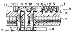
- FIG. 3 shows a modeled cross section of the stator 31.
- the connecting portions 51, 52, and 53 are used to connect the stator coil 33 to a predetermined multiphase winding shape or to connect the stator coil 33 to a power line.
- the stator 31 has three connection parts 51, three connection parts 52, and three connection parts 53.
- One connecting portion 51 has a coil end 33 a and a terminal 71.
- the connecting portion 51 electrically connects the coil end 33a and the terminal 71.
- the terminal 71 is formed on a part of the electrode 72 supported by the stator 31.
- the plurality of terminals 71 are formed on a common electrode 72.
- a coil end 33 a is connected to each terminal 71.
- the terminal 71 protrudes from the insulator 35 in order to be connected to the coil end 33a.
- the connection part 51 has a protective member for protecting the coil end 33a and the terminal 71.
- the protective member includes a protective resin 61 and a wall member 62.
- the wall member 62 is provided by a member separate from the insulator 35.
- the wall member 62 may be formed integrally with the insulator 35.
- the connection unit 51 is used for neutral point connection for star connection.
- the terminal 71 is used for connection with a current-carrying member made of aluminum-based metal.
- An example of the energizing member is the coil end 33a.
- the terminal 71 is used for connection with the coil end 33a.
- the terminal 71 has a shape suitable for a solid connection such as a fusion connection in which the terminal 71 and / or the current-carrying member are temporarily melted to connect them, or diffusion bonding.
- the terminal 71 is supported so as to extend along the axial direction of the stator 31.
- the terminal 71 is made of metal suitable for welding with the coil end 33a made of aluminum metal.
- the terminal 71 is formed so as to be sandwiched between a pair of welding electrodes that are opened and closed, and is disposed on the stator 31.
- the terminal 71 and the coil end 33a are welded by electrical resistance welding or spot welding, and are electrically and mechanically joined.
- the electrode 72 is an electrode for neutral point connection.
- the electrode 72 has a plurality of terminals 71.
- the electrode 72 is supported by the insulator 35 by being insert-molded or inserted into the insulator 35.
- the electrode 72 is disposed so that the plurality of terminals 71 are positioned on one end face of the stator 31.
- the electrode 72 is also called a bus bar.
- the electrode 72 is also called a multi-head electrode or a neutral point electrode.
- the electrode 72 is disposed on one end face of the stator 31.
- the electrode 72 does not penetrate the stator core 32 in the axial direction.
- the electrode 72 is also called a non-penetrating electrode.
- One connecting portion 52 has a coil end 33 a and a terminal 71.
- the connection part 52 electrically connects the coil end 33 a and the terminal 71.
- the terminal 71 is formed on a part of the electrode 73 supported by the stator 31.
- the terminal 71 is also called a main terminal in the electrode 73 or a first terminal.
- the connection part 52 has a protection member for protecting the coil end 33 a and the terminal 71.
- the protective member includes a protective resin 61 and a wall member 62.
- the connection part 52 is used for connecting the stator coil 33 to the electrode 73.
- the connection unit 52 is used to connect the output end of the star connection to an external circuit.
- connection portion 53 includes a wire harness 15 and a terminal 74.
- the connection part 53 electrically connects the wire harness 15 and the terminal 74.
- the terminal 74 is formed on a part of the electrode 73 supported by the stator 31.
- the terminal 74 is also called another terminal in the electrode 73 or a second terminal.
- the connection portion 53 is used to connect the electrode 73 to the power line of the wire harness 15.
- the connection unit 53 is used to connect the output end of the star connection to an external circuit.
- the three connection parts 53 are electrically insulated from each other.
- the electrode 73 is an electrode for providing a part of the power line.
- the electrode 73 provides a connection between the output end of the stator coil 33 and the power line of the wire harness 15.
- At least one terminal 71 is formed on the electrode 73.
- At least one terminal 74 is formed on the electrode 73.
- the electrode 73 has a terminal 71 at one end and a terminal 74 at the other end.
- the electrode 73 is supported by the insulator 35 by being insert-molded or inserted into the insulator 35.
- the electrode 73 is also called a bus bar.
- the electrode 73 is disposed so as to protrude from both end faces of the stator 31.
- the electrode 73 is disposed through the stator core 32.
- the electrode 73 is also called a through electrode.
- the terminal 74 is used for connection with the power line of the wire harness 15.
- the terminal 74 has a shape suitable for connection with a power line.
- the terminal 74 has a shape suitable for connecting a bonding material for connecting the terminal 74 and the wire harness 15 by connecting the bonding material 81 between the terminal 74 and the wire harness 15.
- Solder is applied as a bonding material 81 between the terminal 74 and the wire harness 15.
- the terminal 74 has a shape suitable for soldering. In the figure, an amorphous bonding material 81 is indicated by a broken line.
- the connection portion 53 is a bonding material connection portion that arranges a bonding material 81 made of a low melting point alloy between the terminal 74 and the wire harness 15. As the bonding material 81, solder or brazing material can be used.
- the terminal 74 is also called a bonding material terminal. When the bonding material 81 is solder, the terminal 74 is also called a solder terminal.
- the terminal 74 has an arm for embedding a multi-core electric wire.
- the terminal 74 may be deformed so as to mechanically tighten the wire harness 15. Therefore, the connection part 53 can also function as a solid phase connection part that provides electrical continuity by bringing the surface of the terminal 74 into contact with the wire harness 15 without melting the terminal 74 and the wire harness 15. it can.
- the electrode 73 is a heterogeneous terminal electrode having a plurality of terminals 71 and 74 that differ in at least one of the manufacturing method, function, and structure.
- the shape of the terminal 71 and the shape of the terminal 74 are different.
- the electrode 73 can also be referred to as a heterogeneous terminal electrode having a plurality of terminals 71 and 74 having different shapes.
- the connection structure at the terminal 71 is different from the connection structure at the terminal 74.
- the electrode 73 can also be referred to as a heterogeneous terminal electrode having a plurality of terminals 71 and 74 having different connection structures. The difference in structure is shown by the presence or absence of the protective resin 61.
- the difference in structure appears in the difference between melting and non-melting of the material forming the terminal.
- the difference in structure is shown by the presence or absence of the bonding material 81.
- the connection method applied to the terminal 71 and the connection method applied to the terminal 74 are different.
- the electrode 73 can also be referred to as a heterogeneous terminal electrode having a plurality of terminals 71 and 74 to which different connection methods are applied.
- the coil end 33a connected at the terminal 71 is made of aluminum metal, and the wire harness 15 connected at the terminal 74 is made of copper metal.
- the material connected at the terminal 71 is different from the material connected at the terminal 74.
- the electrode 73 can also be referred to as a heterogeneous terminal electrode having a plurality of terminals 71 and 74 connected to conductors of different materials.
- a plurality of terminals 71 are arranged at one end of the stator 31 in the axial direction. In the illustrated example, six terminals 71 are arranged. A terminal 71 is not disposed at the other axial end of the stator 31. A plurality of terminals 74 are arranged at the other end of the stator 31. In the illustrated example, three terminals 74 are arranged. A terminal 74 is not disposed at one end of the stator 31.
- the protective resin 61 is an electrically insulating resin.
- the protective resin 61 is closely attached to the surfaces of the coil end 33 a and the terminal 71.
- the protective resin 61 is applied or dropped in an uncured state, and is cured after adhering to the surfaces of the coil end 33 a and the terminal 71.
- the protective resin 61 is also called potting resin or sealing resin.
- the wall member 62 surrounds the connection portions 51 and 52 on the end surface of the stator 31.
- the wall member 62 is made of an electrically insulating resin.
- the wall member 62 forms an enclosing wall that surrounds the coil end 33 a and the terminal 71.
- the surrounding wall is formed by the wall member 62 and the insulator 35.
- a storage tank for storing the protective resin 61 is partitioned by the surrounding wall.
- the wall member 62 is disposed on the insulator 35 so as to surround the coil end 33 a and the terminal 71.
- the wall member 62 partitions the storage tank on the end surface of the stator 31. Specifically, the wall member 62 defines a storage tank on the insulator 35.
- the wall member 62 is used to limit the range to which the protective resin 61 is applied.
- the wall member 62 is used to hold the protective resin 61 having a predetermined thickness.
- the wall member 62 is formed to mesh with the components of the stator 31 so as to suppress the outflow of the protective resin 61.
- the wall member 62 is connected to the insulator 35 so that the outflow of the protective resin 61 can be suppressed.
- the wall member 62 receives the coil end 33a so that the outflow of the protective resin 61 can be suppressed.
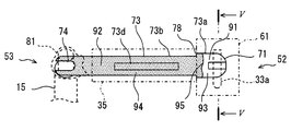
- FIG. 4 is an enlarged view showing the electrode 73.
- the wire harness 15, the coil end 33a, the insulator 35, and the sealing resin 61 are indicated by a broken line or a one-dot chain line.
- the electrode 73 is an elongated plate-like member.
- the electrode 73 includes a wide portion 73 a that provides the terminal 71 and a narrow portion 73 b that provides the terminal 74.
- the wide portion 73a is formed in a D shape.
- the wide part 73a can also be called a welding terminal part.
- the wide portion 73 a is disposed so as to protrude from the end surface of the insulator 35 in the axial direction of the stator 31.
- the wide portion 73 a is wrapped with a protective resin 61.
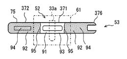
- FIG. 5 is a cross-sectional view taken along line VV in FIG.
- the terminal 71 has a plate-like base portion 71a and a peak portion 71b that protrudes in the direction in which the coil end 33a is positioned.
- the peak portion 71b provides a ridge line that intersects the coil end 33a. The ridge line facilitates deformation of the coil end 33a and promotes current concentration in the spot welding process.
- the narrow portion 73 b extends so as to penetrate the stator 31. Many portions of the narrow width portion 73 b are disposed in the insulator 35. Further, the narrow width portion 73 b is disposed so as to protrude from the end surface of the insulator 35 in the axial direction of the stator 31. The protruding portion of the narrow width portion 73 b provides a terminal 74. The terminal 74 is connected to the wire harness 15. A bonding material 81 is applied to the terminal 74.
- a stepped portion for providing a positioning portion 78 is provided between the wide portion 73a and the narrow portion 73b.
- the positioning portion 78 provides an edge facing the end surface of the insulator 35.
- the manufacturing method of the rotating electrical machine 10 includes the step of inserting the electrode 73 into the insulator 35
- the positioning unit 78 provides a stopper that defines the amount of insertion of the electrode 73 into the insulator 35.
- the positioning portion 78 is used for projecting and positioning the terminal 71 with respect to the stator 31, that is, for projecting the terminal 71 from the insulator 35.
- the narrow width portion 73 b has a protrusion 73 d for fixing the electrode 73 to the insulator 35.
- the protrusion 73d provides strong contact with the inner surface of the accommodation hole provided by the insulator 35.
- the portion disposed in the insulator 35 is a fixing portion for fixing the electrode 73 to the stator 31.
- the protrusion 73d is a part of the fixed part.
- the fixing portion is provided between the terminal 71 and the terminal 74.
- the electrode 73 has a base material 91 and a film 92.
- the base material 91 defines the shape of the electrode 73.
- the base material 91 is made of an iron-based metal such as a cold rolled steel plate.
- the base material 91 may be made of copper metal or aluminum metal.
- the base material 91 contains a surface treatment layer.
- the coating 92 is a metal thin film partially provided on the surface of the base material 91 in order to protect the electrode 73.
- the film 92 protects the electrode 73 from rust and corrosion.
- the film 92 is made of a material suitable for bonding with the bonding material 81.
- the material of the film 92 is a material that exhibits high wettability with respect to the bonding material 81 in a molten state.
- the film 92 is a tin plating layer.
- the tin plating layer protects the electrode 73 from rust and exhibits high affinity with solder.
- the material of the film 92 is a material that satisfies the required level of corrosion resistance and is suitable for bonding to the bonding material 81.
- a base material region 93 and a film region 94 are spread on the surface of the electrode 73.
- a boundary line 95 that divides them lies between the base material region 93 and the coating region 94.
- the boundary line 95 is also an edge of the base material region 93 or the coating region 94.
- a base material 91 that forms the electrode 73 is exposed in the base material region 93. In other words, the material forming the base material 91 is exposed in the base material region 93.
- the base material 91 is a surface-treated steel sheet, the surface treatment layer formed on the base material 91 is exposed in the base material region 93.
- the boundary line 95 is located within the range of the terminal 71.
- the boundary line 95 is located within the range of the wide portion 73a.
- the boundary line 95 is located closer to the terminal 71 than the positioning portion 78.
- the boundary line 95 is located within a range that is surrounded by the protective resin 61. Therefore, the protective resin 61 covers the entire base material region 93. Further, the protective resin 61 covers a part of the film region 94.
- the protective resin 61 covers only a narrow width range adjacent to the boundary line 95 in the coating region 94.
- the boundary line 95 is positioned between the coil end 33a, which is a conductor to be connected, and the insulator 35, which is a member that fixes the electrode 73.
- the protective resin 61 covers the entire base material region 93 in the terminal 71.
- the protective resin 61 covers a part of the coating region 94 in the vicinity of the boundary line 95, that is, a region having a predetermined width. Further, the protective resin 61 covers the exposed metal region of the coil end 33 a as a conductor on the terminal 71.
- the protective resin 61 covers at least a region of the coil end 33a where the film is peeled off. Furthermore, the protective resin 61 also covers the film on the coil end 33a.
- the coil end 33a and the electrode 73 are welded.
- the film 92 is not formed. Therefore, the component that forms the film 92 is mixed in the melt mark formed by temporarily melting the coil end 33a and / or the electrode 73. do not do. For this reason, the malfunction resulting from the component which forms the membrane
- the protective resin 61 contacts the base material region 93.
- the protective resin 61 can completely cover the exposed metal portion that needs to be protected by the protective resin 61. For this reason, the malfunction resulting from the peeling which generate
- This peeling includes peeling at the interface between the film 92 and the substrate 91, the interface between the film 92 and the protective resin 61, or the inside of the film 92.
- the tin plating of this example has a relatively low melting point. Therefore, the mechanical strength of the tin plating may decrease due to the influence of heat generated by the heat received from the internal combustion engine or energized. As a result, the tin plating may be broken and peeled off. According to this embodiment, the plating of the site to be protected can be eliminated. As a result, it is possible to employ the protective resin 61 that exhibits a strong adhesive force in the base material region 93.
- the protective member 61 is also in contact with the film region 94 in the vicinity of the boundary line 95. Thereby, exposure of the base material region 93 is avoided. For example, even when a corrosive material such as water enters from the gap between the insulator 35 and the electrode 73 or from the boundary between the insulator 35 and the protective resin 61, it directly reaches the base material region 93. Is blocked. Furthermore, since the boundary line 95 is positioned closer to the terminal 71 than the positioning portion 78, the protective resin 61 reliably contacts the coating region 94. As a result, even if the base material region 93 is formed, the corrosion of the base material region 93 is suppressed. Furthermore, corrosion of the coil end 33a made of an aluminum-based metal is suppressed.
- the electrode 72 also in the electrode 72, a base material region 93 and a coating region 94 are formed.
- the electrode 72 has a plurality of terminals 71 of the same type. Also in the connection part 51 using the electrode 72, a favorable electrical connection between the coil end 33a, which is a conductor made of aluminum metal, and the electrode 72 is realized. Further, corrosion of the coil end 33a and / or the terminal 71 is suppressed.
- the coating 92 In the electrode 72 and the electrode 73, by providing the coating 92, the generation of rust and corrosion during the period in which the electrodes 72 and 73 are stored are suppressed.
- the coating 92 is formed at a portion that contacts the insulator 35 that is a member for fixing the electrodes 72 and 73, stable fixation can be provided.
- rust or corrosion makes manufacture difficult.
- membrane 92 covers the terminal 74, the bad influence of rust or corrosion is suppressed in the connection part 53 formed with comparatively small energy.
- connection portions 51 and 52 formed by welding with relatively large energy problems caused by coating 92 are suppressed.
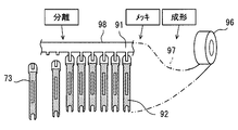
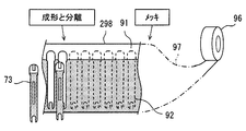
- FIG. 6 shows a method for manufacturing the electrode 73 in the method for manufacturing the rotating electrical machine 10.
- the electrode 72 is also manufactured by a similar manufacturing method.
- the manufacturing method includes a step of supplying the material plate 97.
- the material plate 97 is supplied from a hoop material 96 of a cold rolled steel plate or a hot rolled steel plate.
- the manufacturing method includes a forming process, a plating process, and a separation process. In the molding process, the strip-shaped material plate 97 is molded into the illustrated shape. In this example, a shape in which a plurality of electrodes 73 are connected to a frame 98 is provided.
- the forming process is provided by a pressing process.
- the material plate 97 is partially plated.
- a striped base material region 93 and a coating region 94 are formed on the material plate 97 along the length direction thereof.
- the film 92 is formed in the film region 94.
- the film region 94 is formed on both surfaces along one edge in the longitudinal direction of the material plate 97.
- the base material region 93 and the coating region 94 are formed so that the boundary line 95 is positioned on the terminal 71.
- a connecting portion between the electrode 73 and the frame 98 is positioned in the base material region 93.
- the electrode 73 is separated from the frame 98.
- the film 92 is also formed on the edge of the electrode 73.
- the manufacturing method of the rotating electrical machine 10 includes a process of mounting the electrodes 72 and 73.
- the electrodes 72 and 73 are insert-molded in the insulator 35 or inserted into the insulator 35.
- the positioning portion 78 is used to define the position of the electrode 73 in the axial direction.
- the base material region 93 is treated to prevent rust generation, that is, corrosion.
- the electrode 73 can be stored immersed in oil. Oil or a water-repellent solvent may be applied to the substrate region 93. A thin oil or resin film may be formed on the base material region 93. In this case, in order not to inhibit the adhesion between the protective resin 61 and the base material region 93, it is desirable to provide a step of removing the oil or resin film before the step of applying the protective resin 61. Further, an oil or resin material that does not inhibit the adhesion between the protective resin 61 and the base material region 93 may be selected.
- the manufacturing method of the rotating electrical machine 10 includes a welding process of welding the coil end 33 a and the terminal 71.
- the coil end 33 a is disposed so as to contact the terminal 71.
- the coil end 33a and the terminal 71 are sandwiched between electrodes for welding, and current is supplied. Thereby, the coil end 33a and the terminal 71 are welded.
- the manufacturing method of the rotating electrical machine 10 includes a joining step in which the wire harness 15 and the terminal 74 are connected by the joining material 81.
- the welding process for all terminals 71 is performed on one end of the stator 31, and the joining process is performed on the other end of the stator 31. Thereby, the contamination of the terminal 74 by the sputter
- a joining process is performed after a welding process. This prevents the long and flexible wire harness 15 from interfering with the welding process.
- a good electrical connection between the coil end 33a, which is an aluminum-based metal conductor, and the electrode 73 is realized in the connection portion 52. Further, corrosion of the coil end 33a and / or the terminal 71 is suppressed. As a result, a highly reliable rotating electrical machine 10 can be provided.
- This embodiment is a modification based on the preceding embodiment.
- the plating step is performed after the electrode 73 is formed.
- the coating 92 on the electrode 73 can be formed by various methods.
- the electrode 73 is formed after the plating step.
- the method for manufacturing the electrode 73 includes a molding and separation process after the plating process.
- a striped base material region 93 and a film region 94 are formed on the material plate 97.
- the electrode 73 is cut out from the material plate 97 and the frame 298 is left.
- the molding and separation processes can be performed by a pressing process.
- the terminal 71 is provided at the ends of the electrodes 72 and 73.
- the terminal 71 can be provided at various positions on the electrode.
- the stator 31 includes a plurality of electrodes 372, a connection member 377, and a plurality of electrodes 373.
- the plurality of electrodes 372 and the connection member 377 provide a neutral point connection.
- the electrode 373 provides part of the power line.
- the electrode 372 and the electrode 373 are heterogeneous terminal electrodes.
- the electrode 372 is an I-shaped plate conductor. One end of the electrode 372 is fixed to the insulator 35. One end of the electrode 372 provides a fixing portion. The other end of the electrode 372 protrudes and extends from the surface of the protective resin 61. The other end of the electrode 372 has a terminal 376. The terminal 376 is connected to a connection member 377 made of a conductor by a bonding material 81. The connection member 377 is connected to the three electrodes 372.
- the electrode 372 includes a terminal 371 between the terminal 376 and the fixed portion. A coil end 33 a is welded to the terminal 371.
- the protective resin 61 covers the coil end 33a and the terminal 371.
- the electrode 373 is an L-shaped plate conductor. One end of the electrode 373 is fixed to the insulator 35. One end of the electrode 373 provides a fixing part. The other end of the electrode 373 protrudes and extends from the surface of the protective resin 61. The other end of the electrode 373 has a terminal 74.
- the electrode 373 includes a terminal 371 between the terminal 74 and the fixed portion. A coil end 33 a is welded to the terminal 371.
- the protective resin 61 covers the coil end 33a and the terminal 371.
- FIG. 9 is an enlarged view of the electrode 372.
- the terminal 371 in the electrode 373 also has the form shown in the figure.
- the electrode 372 has a terminal 371 at the center in the longitudinal direction.
- a base material region 93 is formed corresponding to the terminal 371.
- the base material region 93 is formed so as to surround the central portion of the electrode 373.
- the electrode 372 has a coating region 94 at both ends thereof.
- the electrode 372 has two boundary lines 95.
- the two boundary lines 95 are positioned within the range covered with the protective resin 61. Therefore, the protective resin 61 directly contacts the film region 94 in the vicinity of the boundary line 95.
- a good electrical connection between the coil end 33a, which is an aluminum-based metal conductor, and the electrodes 372 and 373 is realized in the connection portion 52. Further, corrosion of the coil end 33a and / or the terminal 371 is suppressed. As a result, a highly reliable rotating electrical machine 10 can be provided.
- Electrode 73 is I-shaped and the electrode 373 is L-shaped. Instead of these, various shapes of electrodes can be employed. Furthermore, a protective resin that does not require the wall member 62 may be used.
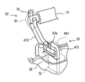
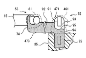
- the electrode 473 is Y-shaped.
- the electrode 473 is a heterogeneous terminal electrode.
- the electrode 473 is fixed to the insulator 35 by one end.
- the electrode 473 has a terminal 74 at the other end.
- the electrode 473 further has a terminal 471 at one other end.
- the two coil ends 33a and the terminals 471 are welded. Such a structure can be used when two coils are connected in parallel in a star connection. Such a structure can also be used for one output end in the delta connection.
- the base material region 93 is formed at one end of the electrode 473.
- the film region 94 is formed between the two ends of the electrode 473. Therefore, the boundary line 95 is formed so as to surround one end portion.
- the protective resin 461 covers the two coil ends 33a and the terminal 471. The protective resin 461 is applied by dropping or coating. The protective resin 461 covers the film region 94 in the vicinity of the boundary line 95.
- a good electrical connection between the coil end 33a, which is an aluminum-based metal conductor, and the electrode 473 is realized in the connection portion 52. Further, corrosion of the coil end 33a and / or the terminal 471 is suppressed. As a result, a highly reliable rotating electrical machine 10 can be provided.
- Electrode 73 is disposed so as to penetrate the stator 31.
- the electrodes can be arranged in various forms.
- the electrode 573 is a heterogeneous terminal electrode.
- the electrode 573 has a terminal 71 at one end and a terminal 74 at the other end.
- the electrode 573 is disposed at one end of the stator 31 without penetrating the stator 31.
- the electrode 573 is fixed to a resin holder 535.
- the holder 535 is fixed to the stator 31.
- the electrode 573 extends along the stator 31 on one end of the stator 31.
- the coil end 33 a and the terminal 71 are covered with a protective resin 461.
- a good electrical connection between the coil end 33a, which is an aluminum-based metal conductor, and the electrode 573 is realized in the connection portion 52. Further, corrosion of the coil end 33a and / or the terminal 71 is suppressed. As a result, a highly reliable rotating electrical machine 10 can be provided.
- This embodiment is a modification based on the preceding embodiment.
- the electrode 73 has the positioning portion 78.
- the positioning part can be formed in various forms. This embodiment provides one form of the positioning part.
- FIG. 13 shows the front of the electrode 673.
- FIG. 14 shows the side of the electrode 673.
- the electrode 673 has a positioning portion 678 provided by a crank portion formed in a crank shape. The positioning portion 678 contacts the end surface of the insulator 35.
- the electrode 673 is manufactured by bending a metal plate into a crank shape.
- the electrode 673 is inserted into the insulator 74 from the terminal 74. At the end of the insertion process, the positioning portion 678 abuts against the end surface of the insulator 35, whereby the terminal 71 is disposed so as to protrude from the insulator 35.
- the electrode 673 has a saw-toothed edge 673 e for meshing with the insulator 35.
- the serrated edge 673e can also be added to the previous and subsequent embodiments.
- the protrusion 73d and the edge 673e provide a strong connection between the insulator 35 and the electrode 673. Also in this embodiment, it is possible to obtain the same effect as the preceding embodiment.
- This embodiment is a modification based on the preceding embodiment. This embodiment provides one form of the positioning part.
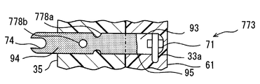
- the electrode 773 is insert-molded in the insulator 35.
- the electrode 773 has positioning portions 778a and 778b for positioning the electrode 773 at a predetermined position by receiving the resin material forming the insulator 35.
- the positioning portion 778a is provided by a notch formed at the edge of the electrode 773.
- the positioning portion 778 b is provided by a through hole that penetrates the electrode 773. Note that the electrode 773 may be formed to include at least one of the positioning portion 778a and the positioning portion 778b.
- the method for manufacturing the rotating electrical machine 10 includes a step of insert-molding the electrode 773 into the insulator 35.
- the positioning portions 778a and 778b receive the resin material in the insert molding process, and position the portion of the electrode 773 to be the terminal 71 so as to protrude from the insulator 35. Also in this embodiment, it is possible to obtain the same effect as the preceding embodiment.
- This embodiment is a modification based on the preceding embodiment. This embodiment provides one form of the positioning part.
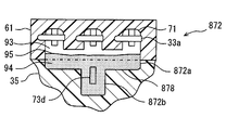
- electrode 872 provides a neutral point connection.
- the electrode 872 has a wide portion 872a and a narrow portion 872b.
- the narrow width portion 872b is inserted deeper into the insulator 35 than the wide width portion 872a.
- a positioning portion 878 is formed by a step portion between the wide portion 872a and the narrow portion 872b. Also in this embodiment, it is possible to obtain the same effect as the preceding embodiment.
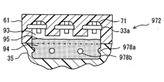
- electrode 972 provides a neutral point connection.
- the electrode 972 is insert-molded in the insulator 35.
- the electrode 972 includes positioning portions 978a and 978b that receive the resin material of the insulator 35. Also in this embodiment, it is possible to obtain the same effect as the preceding embodiment.
- the disclosure in this specification is not limited to the illustrated embodiments.
- the disclosure encompasses the illustrated embodiments and variations by those skilled in the art based thereon.
- the disclosure is not limited to the combinations of parts and / or elements shown in the embodiments.
- the disclosure can be implemented in various combinations.
- the disclosure may have additional parts that can be added to the embodiments.
- the disclosure includes those in which parts and / or elements of the embodiments are omitted.
- the disclosure encompasses the replacement or combination of parts and / or elements between one embodiment and another.
- the technical scope disclosed is not limited to the description of the embodiments. Some technical scope disclosed is shown by the description of the scope of claims, and should be understood to include all modifications within the meaning and scope equivalent to the description of the scope of claims.
- the rotating electrical machine 10 is a motor generator.
- the rotating electrical machine 10 may be a generator.
- the rotating electrical machine 10 may be an electric motor.
- the stator coil 33 provides a three-phase winding.
- the stator coil 33 may provide a single phase winding.
- the stator 31 does not require the electrode 72.
- the stator 31 includes two electrodes 73.
- the stator coil is made of an aluminum-based metal.
- the stator coil may be made of a copper-based metal such as copper or a copper alloy, or a metal obtained by combining copper and an aluminum-based metal.
- the base material of the electrodes 72, 372, 73, 373, and 473 is made of an iron-based metal.
- the base material of the electrodes 72, 372, 73, 373, and 473 may be made of copper-based metal, brass, or aluminum-based metal.
- the wire harness 15 and the connection member 377 are made of copper-based metal. Instead of this, the wire harness 15 and the connection member 377 may be made of an aluminum-based metal.
- connection portion 52 is a fusion connection portion in which one or both of the terminal 71 and the coil end 33a are melted by a spot welding method.
- the fusion connection may be formed by various heating methods such as electrical resistance heating, laser heating, electron beam heating, arc heating, burner heating, and friction heating.
- the fusion connection may be formed by laser welding or TIG welding.
- the connection part 52 may be a non-melting connection part that does not melt the base material of the terminal 71.
- the connection part 52 may be a solid phase connection part formed by diffusion bonding, fusing, or the like.
- connection portion 53 that connects the terminal 74 and the wire harness 15 is a solder connection portion.
- the connecting portion 53 may be a brazed connecting portion using a brazing material.
- a brazing material for example, an aluminum alloy brazing material can be used.
- the connection part 53 may be a fusion connection part.
- the connection part 53 may be a solid phase connection part.
- the coating 92 is tin (Sn) plating.
- the film 92 may be copper (Cu) plating, nickel (Ni) plating, or a multilayer plating film containing at least two of tin, copper, and nickel.
- the film 92 is formed by a partial plating method.
- the base material region 93 may be formed by removing a part of the tin plating after the entire tin plating is formed. For example, after the tin plating is formed on the entire electrode 73, the tin plating in the region including the peak portion 71b and a part of the base portion 71a may be removed. The removal can be performed by mechanical processing such as cutting or chemical treatment with acid or the like.
- the positioning part 78 is formed between the wide part 73a and the narrow part 73b.
- a width direction protrusion for forming the positioning portion 78 may be formed.
- the electrodes 72, 73, 372, 373, 473 may include additional protrusions, recesses, wedge-shaped protrusions, etc. to provide a strong connection with the insulator 35 or the holder 535.
- the protective resin 61 is a resin that protects the coil end 33a and the terminal 71 from corrosion.
- the protective resin 61 may be a resin that protects the coil end 33a and the terminal 71 from deformation due to vibration.
- the bonding material 81 and the terminal 74 are exposed.
- a protective resin may be applied to the bonding material 81 and the terminal 74 as well.
- the protective resin 61 may be applied to the bonding material 81 and the terminal 74.
- a resin for fixing the stator coil 33 to the bonding material 81 and the terminal 74 may be applied.
- a paint may be applied to the bonding material 81 and the terminal 74.
- one electrode 73 has one welding terminal 71.
- one electrode may have a plurality of welding terminals 71.
- the coil end 33 a may be connected to each of the plurality of terminals 71.
- Such an electrode can be used in applications where delta connection is used and / or where multiple coils are connected in parallel.
Landscapes
- Engineering & Computer Science (AREA)
- Power Engineering (AREA)
- Insulation, Fastening Of Motor, Generator Windings (AREA)
- Windings For Motors And Generators (AREA)
- Connections Effected By Soldering, Adhesion, Or Permanent Deformation (AREA)
Priority Applications (1)
| Application Number | Priority Date | Filing Date | Title |
|---|---|---|---|
| CN201680066735.1A CN108307668B (zh) | 2015-11-27 | 2016-11-21 | 内燃机用旋转电机及其电极 |
Applications Claiming Priority (2)
| Application Number | Priority Date | Filing Date | Title |
|---|---|---|---|
| JP2015-231966 | 2015-11-27 | ||
| JP2015231966A JP6206471B2 (ja) | 2015-11-27 | 2015-11-27 | 内燃機関用回転電機およびその電極 |
Publications (1)
| Publication Number | Publication Date |
|---|---|
| WO2017090552A1 true WO2017090552A1 (ja) | 2017-06-01 |
Family
ID=58764026
Family Applications (1)
| Application Number | Title | Priority Date | Filing Date |
|---|---|---|---|
| PCT/JP2016/084429 Ceased WO2017090552A1 (ja) | 2015-11-27 | 2016-11-21 | 内燃機関用回転電機およびその電極 |
Country Status (3)
| Country | Link |
|---|---|
| JP (1) | JP6206471B2 (enExample) |
| CN (1) | CN108307668B (enExample) |
| WO (1) | WO2017090552A1 (enExample) |
Cited By (1)
| Publication number | Priority date | Publication date | Assignee | Title |
|---|---|---|---|---|
| US20210021060A1 (en) * | 2018-03-28 | 2021-01-21 | Wobben Properties Gmbh | Method for connecting two conductors composed of different materials and connector and system therefor |
Families Citing this family (5)
| Publication number | Priority date | Publication date | Assignee | Title |
|---|---|---|---|---|
| CN112968563B (zh) * | 2017-02-14 | 2024-12-13 | 电装多利牡株式会社 | 旋转电机及其制造方法 |
| JP7065666B2 (ja) * | 2018-03-27 | 2022-05-12 | 株式会社ミツバ | 接合体、回転電機、及び回転電機の製造方法 |
| JP7548255B2 (ja) * | 2022-03-11 | 2024-09-10 | トヨタ自動車株式会社 | 回転電機のステータ |
| JP7774498B2 (ja) * | 2022-04-13 | 2025-11-21 | 株式会社ミツバ | 回転電機のステータ構造 |
| JPWO2024185370A1 (enExample) * | 2023-03-03 | 2024-09-12 |
Citations (8)
| Publication number | Priority date | Publication date | Assignee | Title |
|---|---|---|---|---|
| JPS63170871A (ja) * | 1987-01-09 | 1988-07-14 | 住友電気工業株式会社 | スポツト溶接用ニツケルメツキ付金属端子 |
| JPH1112781A (ja) * | 1997-06-25 | 1999-01-19 | Matsushita Electric Works Ltd | 部分メッキ工法および装置 |
| JP2008251981A (ja) * | 2007-03-30 | 2008-10-16 | Nippon Chemicon Corp | コンデンサ用リード端子の製造方法 |
| JP4825906B2 (ja) * | 2009-08-28 | 2011-11-30 | 株式会社オートネットワーク技術研究所 | アルミ電線と銅端子の接続構造およびこの接続構造を有する銅端子付きアルミ電線 |
| WO2012077740A1 (ja) * | 2010-12-08 | 2012-06-14 | 古河電気工業株式会社 | 圧着端子及び、接続構造体並びに、これらの製造方法 |
| WO2015083623A1 (ja) * | 2013-12-02 | 2015-06-11 | デンソートリム株式会社 | 磁石式発電機 |
| US20150318768A1 (en) * | 2013-01-18 | 2015-11-05 | Robert Bosch Gmbh | Contact element for an electric machine |
| WO2016129287A1 (ja) * | 2015-02-12 | 2016-08-18 | デンソートリム株式会社 | 内燃機関用回転電機およびそのステータ |
Family Cites Families (3)
| Publication number | Priority date | Publication date | Assignee | Title |
|---|---|---|---|---|
| JPS63170870A (ja) * | 1987-12-18 | 1988-07-14 | 富士通株式会社 | コネクタおよびその製造方法 |
| JP5708532B2 (ja) * | 2012-03-08 | 2015-04-30 | 株式会社オートネットワーク技術研究所 | 端子付電線 |
| JP5965751B2 (ja) * | 2012-07-03 | 2016-08-10 | 矢崎総業株式会社 | コネクタ端子及びコネクタ端子の止水方法 |
-
2015
- 2015-11-27 JP JP2015231966A patent/JP6206471B2/ja active Active
-
2016
- 2016-11-21 WO PCT/JP2016/084429 patent/WO2017090552A1/ja not_active Ceased
- 2016-11-21 CN CN201680066735.1A patent/CN108307668B/zh active Active
Patent Citations (8)
| Publication number | Priority date | Publication date | Assignee | Title |
|---|---|---|---|---|
| JPS63170871A (ja) * | 1987-01-09 | 1988-07-14 | 住友電気工業株式会社 | スポツト溶接用ニツケルメツキ付金属端子 |
| JPH1112781A (ja) * | 1997-06-25 | 1999-01-19 | Matsushita Electric Works Ltd | 部分メッキ工法および装置 |
| JP2008251981A (ja) * | 2007-03-30 | 2008-10-16 | Nippon Chemicon Corp | コンデンサ用リード端子の製造方法 |
| JP4825906B2 (ja) * | 2009-08-28 | 2011-11-30 | 株式会社オートネットワーク技術研究所 | アルミ電線と銅端子の接続構造およびこの接続構造を有する銅端子付きアルミ電線 |
| WO2012077740A1 (ja) * | 2010-12-08 | 2012-06-14 | 古河電気工業株式会社 | 圧着端子及び、接続構造体並びに、これらの製造方法 |
| US20150318768A1 (en) * | 2013-01-18 | 2015-11-05 | Robert Bosch Gmbh | Contact element for an electric machine |
| WO2015083623A1 (ja) * | 2013-12-02 | 2015-06-11 | デンソートリム株式会社 | 磁石式発電機 |
| WO2016129287A1 (ja) * | 2015-02-12 | 2016-08-18 | デンソートリム株式会社 | 内燃機関用回転電機およびそのステータ |
Cited By (2)
| Publication number | Priority date | Publication date | Assignee | Title |
|---|---|---|---|---|
| US20210021060A1 (en) * | 2018-03-28 | 2021-01-21 | Wobben Properties Gmbh | Method for connecting two conductors composed of different materials and connector and system therefor |
| US12034261B2 (en) * | 2018-03-28 | 2024-07-09 | Wobben Properties Gmbh | Method for connecting two conductors composed of different materials and connector and system therefor |
Also Published As
| Publication number | Publication date |
|---|---|
| CN108307668A (zh) | 2018-07-20 |
| CN108307668B (zh) | 2019-11-05 |
| JP6206471B2 (ja) | 2017-10-04 |
| JP2017099223A (ja) | 2017-06-01 |
Similar Documents
| Publication | Publication Date | Title |
|---|---|---|
| JP6206471B2 (ja) | 内燃機関用回転電機およびその電極 | |
| JP6079944B2 (ja) | 内燃機関用回転電機およびそのステータ | |
| JP3668661B2 (ja) | 車両用交流発電機 | |
| JP6165702B2 (ja) | 磁石式発電機 | |
| JP6499371B2 (ja) | 回転電機 | |
| JP4906909B2 (ja) | 車両用交流発電機 | |
| CN110291698B (zh) | 旋转电机及其制造方法 | |
| JP6477388B2 (ja) | 回転電機およびその製造方法 | |
| JP5505530B1 (ja) | 回転電機 | |
| JP6087038B1 (ja) | 回転電機 | |
| JP7189396B1 (ja) | 回転電機、回転電機用の電気端子、及び回転電機の製造方法 | |
| JP7774498B2 (ja) | 回転電機のステータ構造 | |
| JP7112589B2 (ja) | 回転電機、およびそのステータ | |
| JP6232003B2 (ja) | 端子、端子構造体及び回転電機 | |
| JP7787006B2 (ja) | 回転電機のステータ構造 | |
| JP2025095605A (ja) | 固定子、固定子の製造方法、及びモータ | |
| JP2023156183A (ja) | 固定子、回転電機、送風機、および固定子の製造方法 | |
| US10790718B2 (en) | Electric motor having stator with solder layer on aluminum exposed portion of terminal wire and method of manufacturing electric motor | |
| JP2020181762A (ja) | ステータユニット、回転電機、及び、ステータユニットの製造方法 | |
| JPWO2020137267A1 (ja) | 端子 |
Legal Events
| Date | Code | Title | Description |
|---|---|---|---|
| 121 | Ep: the epo has been informed by wipo that ep was designated in this application |
Ref document number: 16868499 Country of ref document: EP Kind code of ref document: A1 |
|
| NENP | Non-entry into the national phase |
Ref country code: DE |
|
| 122 | Ep: pct application non-entry in european phase |
Ref document number: 16868499 Country of ref document: EP Kind code of ref document: A1 |