WO2017082248A1 - Dispositif de propulsion de navire - Google Patents
Dispositif de propulsion de navire Download PDFInfo
- Publication number
- WO2017082248A1 WO2017082248A1 PCT/JP2016/083102 JP2016083102W WO2017082248A1 WO 2017082248 A1 WO2017082248 A1 WO 2017082248A1 JP 2016083102 W JP2016083102 W JP 2016083102W WO 2017082248 A1 WO2017082248 A1 WO 2017082248A1
- Authority
- WO
- WIPO (PCT)
- Prior art keywords
- duct
- propulsion device
- marine vessel
- casing
- vessel propulsion
- Prior art date
Links
Images


Classifications
-
- B—PERFORMING OPERATIONS; TRANSPORTING
- B63—SHIPS OR OTHER WATERBORNE VESSELS; RELATED EQUIPMENT
- B63H—MARINE PROPULSION OR STEERING
- B63H5/00—Arrangements on vessels of propulsion elements directly acting on water
- B63H5/07—Arrangements on vessels of propulsion elements directly acting on water of propellers
- B63H5/125—Arrangements on vessels of propulsion elements directly acting on water of propellers movably mounted with respect to hull, e.g. adjustable in direction, e.g. podded azimuthing thrusters
-
- B—PERFORMING OPERATIONS; TRANSPORTING
- B63—SHIPS OR OTHER WATERBORNE VESSELS; RELATED EQUIPMENT
- B63H—MARINE PROPULSION OR STEERING
- B63H1/00—Propulsive elements directly acting on water
- B63H1/02—Propulsive elements directly acting on water of rotary type
- B63H1/12—Propulsive elements directly acting on water of rotary type with rotation axis substantially in propulsive direction
- B63H1/14—Propellers
- B63H1/16—Propellers having a shrouding ring attached to blades
-
- B—PERFORMING OPERATIONS; TRANSPORTING
- B63—SHIPS OR OTHER WATERBORNE VESSELS; RELATED EQUIPMENT
- B63H—MARINE PROPULSION OR STEERING
- B63H20/00—Outboard propulsion units, e.g. outboard motors or Z-drives; Arrangements thereof on vessels
- B63H20/007—Trolling propulsion units
-
- B—PERFORMING OPERATIONS; TRANSPORTING
- B63—SHIPS OR OTHER WATERBORNE VESSELS; RELATED EQUIPMENT
- B63H—MARINE PROPULSION OR STEERING
- B63H20/00—Outboard propulsion units, e.g. outboard motors or Z-drives; Arrangements thereof on vessels
- B63H20/02—Mounting of propulsion units
- B63H20/06—Mounting of propulsion units on an intermediate support
-
- B—PERFORMING OPERATIONS; TRANSPORTING
- B63—SHIPS OR OTHER WATERBORNE VESSELS; RELATED EQUIPMENT
- B63H—MARINE PROPULSION OR STEERING
- B63H23/00—Transmitting power from propulsion power plant to propulsive elements
- B63H23/22—Transmitting power from propulsion power plant to propulsive elements with non-mechanical gearing
- B63H23/24—Transmitting power from propulsion power plant to propulsive elements with non-mechanical gearing electric
-
- B—PERFORMING OPERATIONS; TRANSPORTING
- B63—SHIPS OR OTHER WATERBORNE VESSELS; RELATED EQUIPMENT
- B63H—MARINE PROPULSION OR STEERING
- B63H1/00—Propulsive elements directly acting on water
- B63H1/02—Propulsive elements directly acting on water of rotary type
- B63H1/12—Propulsive elements directly acting on water of rotary type with rotation axis substantially in propulsive direction
- B63H1/14—Propellers
- B63H1/16—Propellers having a shrouding ring attached to blades
- B63H2001/165—Hubless propellers, e.g. peripherally driven shrouds with blades projecting from the shrouds' inside surfaces
-
- B—PERFORMING OPERATIONS; TRANSPORTING
- B63—SHIPS OR OTHER WATERBORNE VESSELS; RELATED EQUIPMENT
- B63H—MARINE PROPULSION OR STEERING
- B63H5/00—Arrangements on vessels of propulsion elements directly acting on water
- B63H5/07—Arrangements on vessels of propulsion elements directly acting on water of propellers
- B63H5/125—Arrangements on vessels of propulsion elements directly acting on water of propellers movably mounted with respect to hull, e.g. adjustable in direction, e.g. podded azimuthing thrusters
- B63H2005/1254—Podded azimuthing thrusters, i.e. podded thruster units arranged inboard for rotation about vertical axis
- B63H2005/1258—Podded azimuthing thrusters, i.e. podded thruster units arranged inboard for rotation about vertical axis with electric power transmission to propellers, i.e. with integrated electric propeller motors
-
- B—PERFORMING OPERATIONS; TRANSPORTING
- B63—SHIPS OR OTHER WATERBORNE VESSELS; RELATED EQUIPMENT
- B63H—MARINE PROPULSION OR STEERING
- B63H23/00—Transmitting power from propulsion power plant to propulsive elements
- B63H2023/005—Transmitting power from propulsion power plant to propulsive elements using a drive acting on the periphery of a rotating propulsive element, e.g. on a dented circumferential ring on a propeller, or a propeller acting as rotor of an electric motor
-
- B—PERFORMING OPERATIONS; TRANSPORTING
- B63—SHIPS OR OTHER WATERBORNE VESSELS; RELATED EQUIPMENT
- B63H—MARINE PROPULSION OR STEERING
- B63H21/00—Use of propulsion power plant or units on vessels
- B63H21/12—Use of propulsion power plant or units on vessels the vessels being motor-driven
- B63H21/17—Use of propulsion power plant or units on vessels the vessels being motor-driven by electric motor
Definitions
- This invention relates to a ship propulsion device.
- ship propulsion devices are known. For example, it is disclosed in JP2013-100013A.
- the above Japanese Unexamined Patent Publication No. 2013-100013 includes a duct in which a stator is disposed, a rim in which a rotor is disposed at a position facing the stator, and a blade formed radially inward of the rim.
- a marine vessel propulsion device is disclosed that includes a propeller, a steering shaft that supports a duct so as to be steerable, and a motor ECU that controls rotational driving of the propeller.
- the motor ECU of this marine vessel propulsion device is arranged inside the steering shaft or in the vessel.
- the present invention has been made to solve the above-described problems, and one object of the present invention is to suppress the increase in size of the apparatus while suppressing the wiring from becoming complicated. It is to provide a possible ship propulsion device.
- a marine vessel propulsion device includes a duct including a stator portion, a rim having a rotor portion disposed at a position facing the stator portion, and blades formed radially inward of the rim.
- a propeller portion a steering shaft that supports the duct so as to be steerable, a steering shaft that is provided separately from the steering shaft and that extends along the rotation axis direction of the propeller portion, and is disposed in the casing portion; And a motor control unit that controls rotation driving of the propeller unit.
- the rotation drive of the propeller unit is controlled in the casing unit that is provided separately from the steering shaft and extends along the rotation axis direction of the propeller unit.
- a motor control unit is arranged.
- a marine vessel propulsion apparatus that can suppress the increase in size of the apparatus while suppressing complicated wiring.
- the casing part By forming the casing part so as to extend along the direction of the rotation axis of the propeller part, it is possible to suppress an increase in water resistance. Can do. Since a casing part can be arrange
- the casing part is preferably fixed to the duct so as to be steerable together with the duct. If comprised in this way, since a duct and a casing part are steered integrally, even when a duct is steered, it can suppress that resistance of water resulting from a casing part becomes large.
- the casing part is provided integrally with the duct. If comprised in this way, compared with the case where a duct and a casing part are provided separately, while being able to reduce a number of parts, the joint surface of a duct and a casing part can be eliminated, so that flooding is effective. Can be suppressed.
- the casing portion is preferably disposed above the duct. If comprised in this way, in order to suppress the entrainment of the air from a water surface, when arranging a duct in the downward direction from a water surface, the space between a duct and a water surface is used effectively, and a casing part is used. Can be arranged.
- At least a part of the casing part is preferably arranged behind the steering shaft. If comprised in this way, since a casing part can be extended back rather than a steering shaft, when turning a casing part with a duct, it suppresses that a casing part interferes with the hull to which a ship propulsion device is attached. can do.
- the casing portion is preferably formed so that at least a part thereof extends rearward from the rear end of the duct. If comprised in this way, even when a motor control part becomes large, since a casing part can be enlarged so that it may extend back rather than the rear end of a duct, a motor control part is easily accommodated in a casing part. be able to.
- the casing part is fixed to the duct at the rear of the duct on the rotation axis of the propeller part. If comprised in this way, since the water flow discharged from a duct can be rectified by a casing part, a ship can be propelled more efficiently.
- the casing portion preferably has a function as a skeg. If comprised in this way, the steerability of a ship can be improved using the casing part by which the motor control part is arrange
- the casing portion has a length in a direction parallel to the rotation axis direction of the propeller portion rather than a length in a direction perpendicular to the rotation axis direction of the propeller portion in a plan view. It is formed to be large. If comprised in this way, since it can suppress that the projection area at the time of seeing a casing part in the rotation-axis direction of a propeller part can become large, it can suppress effectively that resistance of water becomes large. it can.
- a heat radiating part exposed to the outside is provided in the vicinity of the motor control part of the casing part. If comprised in this way, since the heat of a motor control part can be easily discharge
- the motor control unit is provided on a substrate disposed so as to extend substantially parallel to the rotation axis direction of the propeller unit, and the casing unit is a direction in which the substrate extends. It is formed in the elongate shape extended along. If comprised in this way, the board
- the casing portion is preferably formed in a streamlined shape along the rotation axis direction of the propeller portion. If comprised in this way, since the resistance of the water of a casing part can be made small effectively, even if it provides a casing part, a ship can be propelled efficiently.
- the motor control unit preferably includes at least one of a motor driver and an inverter. If comprised in this way, since at least one can be accommodated in the casing part arrange
- the duct is preferably formed so that the cross-sectional shape changes along the rotation axis direction of the propeller portion. If comprised in this way, since the fluid which flows through the inside of a duct can be rectified, a thrust can be generated efficiently.
- 3 or more and 8 or less blades are provided. If comprised in this way, since 3 or more and 8 or less blade
- the marine vessel propulsion device is further provided with a steering mechanism that is disposed above the duct and steers the duct, and the casing portion is disposed between the duct and the steering mechanism. If comprised in this way, a duct can be easily steered by a steering mechanism. In order to suppress the entrainment of air from the water surface, the casing portion can be disposed by effectively utilizing the space between the duct and the steering mechanism when the duct is disposed away from the water surface. .
- the steering mechanism is formed in a streamlined shape along the forward / backward direction. If comprised in this way, since the resistance of the water of a steering mechanism can be made small effectively, a ship can be propelled more efficiently.
- the steering mechanism preferably includes an electric motor and is configured to rotate the steering shaft by driving the electric motor. If comprised in this way, a duct can be easily steered by driving an electric motor.
- the upper surface of the steering mechanism is preferably fixed to a bracket attached to the hull. If comprised in this way, a steering mechanism can be reliably attached to a hull.
- the bracket includes a hull mounting portion and a propulsion device mounting portion. If comprised in this way, while a hull attaching part can be fixed to a hull and a ship propulsion apparatus can be fixed to a propulsion apparatus attaching part, a ship propulsion apparatus can be reliably attached to a hull.
- the marine vessel propulsion device further includes a duct connection portion that is connected to the upper side of the duct and is disposed so as to surround the steering shaft, and the duct connection portion includes the steering shaft disposed in the internal space.
- the radial length of the inner or outer peripheral gap of the collar is smaller than the inner diameter of the through hole. If comprised in this way, even if a foreign material penetrate
- an increase in the size of the apparatus can be suppressed while suppressing the wiring from becoming complicated.
- FIG. 11 is a sectional view taken along line 110-110.
- FIG. 12 is a cross-sectional view taken along line 120-120.
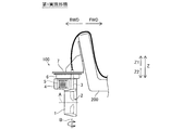
- the ship propulsion apparatus 100 includes an electric propulsion device that propels the hull 200 as shown in FIG.
- the marine vessel propulsion apparatus 100 includes a cylindrical duct 1, a propeller unit 2, a steering shaft 3, a casing unit 4, a motor control unit 5, and a steering mechanism 6.
- the duct 1 includes a stator portion 11.
- the propeller unit 2 includes a rim 21 and a blade 22.
- the rim 21 has a rotor part 23.
- the stator unit 11 and the rotor unit 23 constitute a motor 10 (switched reluctance motor).
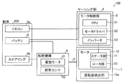
- the ship propulsion apparatus 100 is attached to the hull 200 via the bracket 7 as shown in FIGS. 1 and 6. As shown in FIG. 2, the hull 200 is provided with a battery 8, a remote controller 9a, and a steering wheel 9b.
- the marine vessel propulsion device 100 (motor 10) is connected to the motor control unit 5.
- a battery 8 and a remote controller 9a are further connected to the motor control unit 5.
- the motor control unit 5 includes a CPU (Central Processing Unit) 51, a motor driver 52, and an inverter 53.
- CPU Central Processing Unit
- the marine vessel propulsion device 100 (duct 1) is rotatable around a turning axis B that intersects with the rotation axis A of the propeller unit 2 as shown in FIG.
- the marine vessel propulsion apparatus 100 is steered (turned) by the steered mechanism 6.
- the steered mechanism 6 includes an electric motor 61 and a rudder angle sensor 62 as shown in FIG.
- the turning mechanism 6 turns the duct 1 and the casing part 4 by turning the steering shaft 3.
- the steering mechanism 6 is connected to a battery 8 and a steering wheel 9b.
- the marine vessel propulsion device 100 adjusts the magnitude of the propulsive force by operating the remote controller 9 a.
- the direction of the propulsive force (the direction of the duct 1) is adjusted by operating the steering wheel 9b. That is, by steering the steering wheel 9b, the direction of the ship propulsion device 100 is changed and the rudder of the hull 200 is operated.
- the duct 1 is formed in a cylindrical shape.
- the duct 1 is formed so that the cross-sectional shape changes along the direction of the rotation axis A of the propeller portion 2. That is, the duct 1 is formed so that the X1 direction spreads outward and the X2 direction is gradually narrowed.
- the duct 1 is formed with a circumferential recess that is recessed outward from the inner surface in the radial direction.
- the propeller portion 2 is accommodated in the recess. Specifically, the propeller portion 2 is rotatably supported by the duct 1 via a fluid bearing provided along the concave portion of the duct 1.
- a stator portion 11 is disposed on the outer periphery of the concave portion of the duct 1.
- Stator portion 11 includes a winding.
- the stator unit 11 generates a magnetic field when electric power is supplied to the windings.
- a plurality of windings are arranged circumferentially along the concave portion of the cylindrical duct 1. Electric power is supplied to the plurality of windings in synchronization with the rotational speed. Thereby, the magnetic force of the stator part 11 acts on the rotor part 23 of the propeller part 2, and the propeller part 2 rotates.
- the propeller portion 2 is disposed so as to be rotatable inward in the radial direction of the cylindrical duct 1.
- the rim 21 of the propeller unit 2 is provided in a cylindrical shape outside the blades 22.
- the blades 22 are formed radially inward of the rim 21 from the inner surface of the rim 21. As shown in FIG. 3, four blades 22 are provided at equal intervals (every 90 degrees) along the circumferential direction.
- the blade 22 has a wing shape.
- the rotor part 23 is provided outside the rim 21.
- the rotor part 23 is arranged at a position facing the stator part 11 of the duct 1. Specifically, the rotor part 23 and the stator part 11 are opposed to each other at a predetermined interval in the radial direction. That is, the motor 10 constituted by the stator portion 11 and the rotor portion 23 is a radial gap type motor.
- portions having a high magnetic permeability and portions having a low magnetic permeability are alternately arranged in a circumferential shape. That is, reluctance torque is generated in the rotor portion 23 by the magnetic force generated from the stator portion 11. Thereby, the rotor part 23 (rim
- Steering shaft 3 supports duct 1 so as to be steerable as shown in FIGS. 3 and 4. Specifically, the steering shaft 3 is rotatably supported by the steering mechanism 6 through a tapered roller bearing 31.
- the steering shaft 3 supports a casing portion 4 provided integrally with the duct 1 via a cylindrical roller bearing 32.
- the steering shaft 3 is formed in a hollow shape. Inside the hollow shape of the steering shaft 3 are wiring for supplying electric power to the stator unit 11, wiring for connecting the motor control unit 5 and the battery 8, wiring for connecting the remote control 9a and the motor control unit 5, and a steering wheel 9b. And a wiring for connecting the steering mechanism 6 is accommodated.
- the steering shaft 3 is provided with seals 33 and 34 to prevent water from entering the casing portion 4, the steering mechanism 6, and the stator portion 11. Specifically, a seal 33 is provided between the steering shaft 3 and the steering mechanism 6. A seal 34 is provided between the steering shaft 3 and the casing portion 4.
- the casing portion 4 is provided separately from the steering shaft 3 and is formed so as to extend along the direction of the rotation axis A of the propeller portion 2.
- a motor control unit 5 is disposed in the casing unit 4.
- the casing part 4 is fixed to the duct 1 so as to be steerable together with the duct 1.
- the casing portion 4 is provided integrally with the duct 1.
- Casing part 4 is arranged above duct 1. Specifically, the casing portion 4 is disposed between the duct 1 and the steering mechanism 6. At least a part of the casing part 4 is arranged behind the steering shaft 3. The casing part 4 is formed so that at least a part thereof extends rearward from the rear end of the duct 1. Specifically, the length of the casing part 4 in the direction parallel to the rotation axis A direction of the propeller part 2 is larger than the length of the propeller part 2 in the direction perpendicular to the rotation axis A direction in the plan view. Is formed. That is, the casing part 4 is formed so as to extend along a plane parallel to the rotation axis A direction of the propeller part 2 and parallel to the vertical direction. The casing part 4 has a function as a skeg. In other words, the casing portion 4 also functions as a fin that stabilizes the navigability of the hull 200.
- the casing portion 4 is formed in a streamlined shape along the direction of the rotation axis A of the propeller portion 2. Specifically, the casing part 4 is formed in a streamlined shape so as to reduce resistance to water that flows relatively in the X direction.
- the casing part 4 includes a heat radiating part 41 and a lid part 42.
- the heat dissipating part 41 is arranged in the state exposed to the outside in the vicinity of the motor control part 5 of the casing part 4.
- the heat radiating part 41 is provided so as to release the heat of the motor control part 5 to the outside.
- the heat radiation part 41 is formed of a metal material such as aluminum.
- a plurality of fins extending along the X direction are formed on the outer surface of the heat radiating portion 41. Thereby, since the surface area can be increased, it is possible to efficiently dissipate heat.
- the heat radiating part 41 is provided on one side of the casing part 4 in the left-right direction.
- the lid part 42 is provided on the other side of the casing part 4 in the left-right direction.
- the lid part 42 is provided for taking the motor control part 5 in and out of the casing part 4.
- the lid part 42 is provided so as to cover the motor control part 5.
- the heat radiation part 41 and the lid part 42 are attached to the casing part 4 via a seal. That is, the casing part 4 is sealed with the heat radiating part 41 and the lid part 42 attached thereto.
- the motor control unit 5 controls the rotational drive of the propeller unit 2 (motor 10). Specifically, the motor control unit 5 controls the rotation speed of the motor 10 based on the operation of the remote controller 9a.
- the CPU 51 receives a signal from the rotation speed detection unit 10 a provided in the motor 10. The CPU 51 supplies power to the motor 10 (stator unit 11) via the motor driver 52 and the inverter 53.
- the motor controller 5 (CPU 51, motor driver 52 and inverter 53) is provided on the substrate 5a.
- the substrate 5 a is formed in a flat plate shape.
- the substrate 5a is disposed so as to extend substantially parallel to the direction of the rotation axis A of the propeller unit 2. That is, the board
- substrate 5a is arrange
- the steering mechanism 6 is disposed above the duct 1 and is provided for turning the duct 1.
- the electric motor 61 of the steering mechanism 6 is driven based on the operation of the steering wheel 9b (see FIG. 2).
- the electric motor 61 is rotated by being supplied with electric power from the battery 8 via a driver.
- the electric motor 61 rotates the steering shaft 3 via a worm gear 61a and a gear 3a.
- a reduction gear 61b is provided between the electric motor 61 and the worm gear 61a.
- the speed reducer 61b has a planetary gear.
- the steering angle sensor 62 detects the rotation angle of the steering shaft 3. The detected rotation angle of the steering shaft 3 is feedback controlled, and the electric motor 61 is driven.
- the outer surface of the steering mechanism 6 is formed in a streamline shape along the forward / backward direction. As shown in FIGS. 1 and 6, the upper surface (the surface in the Z1 direction) of the steering mechanism 6 is fixed to a bracket 7 attached to the hull 200.
- the bracket 7 supports the ship propulsion device 100 and is attached to the rear of the hull 200.
- the bracket 7 includes a hull mounting portion 71 and a propulsion device mounting portion 72.
- the hull mounting portion 71 is formed in a flat plate shape.
- the hull attachment portion 71 is attached to the transom behind the hull 200.
- the propulsion device attachment portion 72 is attached to the hull attachment portion 71 with a predetermined angle.
- the propulsion device mounting portion 72 is formed in a substantially horizontal flat plate shape.
- the marine vessel propulsion device 100 is attached to the propulsion device attachment portion 72.
- a plurality of marine vessel propulsion devices 100 can be attached to the propulsion device attachment portion 72.
- the propulsion device attachment portion 72 is provided with a plurality of holes 711 (bolt insertion holes) for attaching the marine vessel propulsion device 100.
- the hull mounting portion 71 is provided with a plurality of holes 711 corresponding to brackets for mounting an outboard motor equipped with an engine.
- the hole portions 711 of the hull mounting portion 71 are arranged in a row at intervals of about 12.8 inches (about 327 mm) in the left-right direction, for example, like the bracket of the outboard motor. Thereby, it is possible to easily attach the ship propulsion device 100 to the hull 200 instead of the outboard motor.
- the propeller unit 2 is rotationally driven in the casing unit 4 that is provided separately from the steering shaft 3 and that extends along the direction of the rotation axis A of the propeller unit 2.
- a motor control unit 5 for controlling is arranged.
- the motor control part 5 and the motor 10 can be arrange
- the motor control unit 5 can be accommodated in the casing unit 4 by enlarging the casing unit 4 along the direction of the rotation axis A of the propeller unit 2. Unlike the case where the diameter of the apparatus is increased, it is possible to prevent the apparatus from becoming excessively large.
- the marine vessel propulsion apparatus 100 that can suppress the apparatus from becoming large while suppressing the wiring from becoming complicated.
- the casing part 4 By forming the casing part 4 so as to extend along the direction of the rotation axis A of the propeller part 2, it is possible to suppress an increase in water resistance. Can be promoted. Since the casing part 4 can be arrange
- the casing portion 4 is fixed to the duct 1 so as to be steerable together with the duct 1.
- the casing portion 4 is provided integrally with the duct 1 as described above. Thereby, compared with the case where the duct 1 and the casing part 4 are provided separately, the number of parts can be reduced, and the joint surface between the duct 1 and the casing part 4 can be eliminated, so that the flooding is effective. Can be suppressed.
- the casing portion 4 is disposed above the duct 1 as described above. Thereby, in order to suppress the entrainment of air from the water surface, when the duct 1 is arranged away from the water surface, the casing 4 is arranged by effectively utilizing the space between the duct 1 and the water surface. can do.
- the casing portion 4 is arranged so that at least a part thereof is behind the steering shaft 3. Thereby, since the casing part 4 can be extended back rather than the steering shaft 3, when the casing part 4 is steered with the duct 1, the casing part 4 interferes with the hull 200 to which the ship propulsion apparatus 100 is attached. Can be suppressed.
- the casing portion 4 is formed so that at least a part thereof extends rearward from the rear end of the duct 1. Thereby, even when the motor control unit 5 becomes large, the casing unit 4 can be enlarged so as to extend rearward from the rear end of the duct 1, so that the motor control unit 5 can be easily accommodated in the casing unit 4. can do.
- the casing portion 4 has a function as a skeg. Thereby, the steerability of a ship can be improved using the casing part 4 in which the motor control part 5 is arrange
- the casing part 4 is longer in the direction parallel to the rotation axis A direction of the propeller part 2 than in the direction perpendicular to the rotation axis A direction of the propeller part 2 in plan view. It is formed so that is larger. Thereby, since it can suppress that the projection area at the time of seeing the casing part 4 in the rotation axis A direction of the propeller part 2 becomes large, it can suppress effectively that resistance of water becomes large. .
- the heat radiation portion 41 exposed to the outside is provided in the vicinity of the motor control portion 5 of the casing portion 4. Therefore, since the heat of the motor control unit 5 can be easily released to the outside (underwater) through the heat radiation unit 41, the motor control unit 5 can be effectively cooled.
- the motor control part 5 is provided on the board
- FIG. It is formed in an elongated shape extending along the direction. Thereby, the board
- the casing part 4 is formed into a streamlined shape along the direction of the rotation axis A of the propeller part 2.
- the motor control unit 5 includes the motor driver 52 and the inverter 53 as described above. Thereby, since the motor driver 52 and the inverter 53 can be accommodated in the casing part 4 arrange
- the duct 1 is formed so that its cross-sectional shape changes along the direction of the rotation axis A of the propeller portion 2.
- 3 to 8 blades 22 are provided. Thereby, since 3 or more and 8 or less blade
- the steering mechanism 6 that is disposed above the duct 1 and that steers the duct 1 is provided, and the casing portion 4 is disposed between the duct 1 and the steering mechanism 6. .
- the duct 1 can be easily steered by the steering mechanism 6.
- the casing portion 4 is arranged by effectively utilizing the space between the duct 1 and the steering mechanism 6 when the duct 1 is arranged away from the water surface. can do.
- the steering mechanism 6 is formed in a streamlined shape along the forward / backward direction. Therefore, since resistance of the water of the steering mechanism 6 can be made small effectively, a ship can be propelled more efficiently.
- the steering mechanism 6 rotates the steering shaft 3 by driving the electric motor 61.
- the duct 1 can be easily steered by driving the electric motor 61.
- the upper surface of the steering mechanism 6 is fixed to the bracket 7 attached to the hull 200 as described above. Thereby, the steering mechanism 6 can be reliably attached to the hull 200.
- the bracket 7 includes the hull attachment portion 71 and the propulsion device attachment portion 72. Thereby, while being able to fix the hull attaching part 71 to the hull 200, the ship propulsion apparatus 100 can be fixed to the propulsion apparatus attaching part 72, the ship propulsion apparatus 100 can be reliably attached to the hull 200. .
- the marine vessel propulsion apparatus 300 includes a cylindrical duct 1, a propeller unit 2, a steering shaft 3, a casing unit 4 a, a motor control unit 5, and a steering mechanism 6.
- the casing portion 4a is provided separately from the steering shaft 3, and is formed so as to extend along the direction of the rotation axis A of the propeller portion 2.
- a motor control unit 5 is disposed in the casing unit 4a.
- the casing part 4 a is formed so that at least a part thereof extends rearward from the rear end of the duct 1.
- the casing part 4 a is fixed to the duct 1 behind the duct 1 on the rotation axis A of the propeller part 2.
- the casing portion 4a is formed to extend in the vertical direction (Z direction) behind the duct 1.
- the propeller portion is provided in the casing portion 4a provided separately from the steering shaft 3 and extending along the direction of the rotation axis A of the propeller portion 2.
- a motor control unit 5 for controlling the rotational driving of 2 is arranged. Thereby, it can suppress that an apparatus enlarges, suppressing wiring becoming complicated.
- the casing portion 4a is fixed to the duct 1 behind the duct 1 on the rotation axis A of the propeller portion 2.
- the ship propulsion device 400 includes a cylindrical duct 1, a propeller unit 2 (see FIG. 11), a steering shaft 3, a casing unit 4 b, a motor control unit 5, and a steering mechanism 6. And.
- the remote control 9 a provided in the hull 200 includes a CPU 91.
- the CPU 91 is connected to the motor control unit 5.
- the CPU 91 controls the rotation drive of the propeller unit 2 (motor 10) via the motor control unit 5.
- the CPU 91 controls the rotation speed of the motor 10 based on the operation of the remote controller 9a.
- the CPU 91 receives a signal from the rotation speed detection unit 10 a provided in the motor 10.
- the CPU 91 supplies electric power to the motor 10 (stator unit 11) via the motor control unit 5 (motor driver 52 and inverter 53).
- the CPU91 controls the steering mechanism 6 based on the operation of the steering wheel 9b.
- the CPU 91 supplies power to the steering mechanism 6 via the motor control unit 5. That is, the CPU 91 performs the control of turning the duct 1 by the turning mechanism 6 via the motor control unit 5 based on the operation of the steering wheel 9b. As a result, it is possible to control the ship maneuvering operation in a concentrated manner by the CPU 91 provided in the hull 200.
- the casing portion 4b is provided separately from the steering shaft 3, and is formed so as to extend along the direction of the rotation axis A of the propeller portion 2 (see FIG. 1).
- a motor control unit 5 is disposed in the casing unit 4b.
- the casing part 4b is being fixed to the duct 1 so that steering with the duct 1 is possible.
- the casing portion 4 b is configured to be connected to a duct connection portion 43 that is connected to the upper side of the duct 1 and is disposed so as to surround the steering shaft 3.
- the casing part 4 b is configured to be detachably attached to the rear of the duct connection part 43.
- the duct 1 is configured to be divided into a central portion 12, a front portion 13, and a rear portion 14.
- a stator portion 11 (see FIG. 10) is arranged in the central portion 12.
- the central portion 12 is connected below the duct connection portion 43.
- the central part 12 and the duct connection part 43 are integrally formed.
- the propeller portion 2 is configured to be attached to the central portion 12 in a state where the central portion 12, the front portion 13, and the rear portion 14 are separated.
- the front portion 13 is connected to the front of the central portion 12.
- the front portion 13 is fixed to the central portion 12 by engaging a screw portion provided on the inner periphery of the central portion 12 with a screw portion provided on the outer periphery of the front portion 13.
- the rear part 14 is connected to the rear of the central part 12.
- the rear portion 14 is fixed to the central portion 12 by engaging a screw portion provided on the inner periphery of the central portion 12 and a screw portion provided on the outer periphery of the rear portion 14.
- the duct connection part 43 is connected above the duct 1 as shown in FIG.
- the duct connecting portion 43 is disposed so as to surround the steering shaft 3.
- the duct connection portion 43 includes a housing portion 431, a collar 432, and a through hole 433.
- casing part 431 has the internal space 43a, as shown in FIG.
- the steering shaft 3 is disposed in the internal space 43 a of the housing portion 431. Specifically, in the internal space 43 a of the housing portion 431, a lower portion of the housing of the steering mechanism 6 and the steering shaft 3 disposed inside the housing of the steering mechanism 6 are disposed.
- the collar 432 is disposed in the internal space 43 a between the housing portion 431 at the upper end of the housing portion 431 and the steering shaft 3.
- the collar 432 is provided in order to reduce the opening area leading to the internal space 43 a of the duct connection portion 43.
- the collar 432 is disposed between the housing portion 431 and the housing of the steering mechanism 6.
- the collar 432 is formed in an annular shape.
- the collar 432 is made of resin.
- the collar 432 is press-fitted so that the outer peripheral portion is in contact with the housing portion 431.
- the length d2 in the radial direction of the gap between the inner periphery and the outer periphery of the collar 432 is configured to be smaller than the inner diameter d1 of the through hole 433.
- the through-hole 433 is configured to communicate the internal space 43a in which the steering shaft 3 is disposed and the outside.
- the through hole 433 is provided below the collar 432 (Z2 direction).
- a total of two through holes 433 are provided, one on the left side and one on the right side of the duct connecting portion 43.
- the through hole 433 is provided in the vicinity of the lower end of the internal space 43 a of the housing portion 431.
- the remaining configuration of the third embodiment is the same as that of the first embodiment.
- the propeller portion is provided in the casing portion 4b which is provided separately from the steering shaft 3 and extends along the rotation axis A direction of the propeller portion 2.
- a motor control unit 5 for controlling the rotational driving of 2 is arranged. Thereby, it can suppress that an apparatus enlarges, suppressing wiring becoming complicated.
- the duct connecting portion 43 includes the housing portion 431 in which the steering shaft 3 is disposed in the internal space 43a, the housing portion 431 at the upper end of the housing portion 431, and the steering shaft 3.
- a collar 432 disposed in the inner space 43a between the inner space 43a and the inner space 43a in which the steering shaft 3 is disposed communicates with the outside, and includes a through-hole 433 provided below the collar 432.
- the collar 432 can prevent foreign matter from entering the duct connecting portion 43 from the upper surface. Even when a foreign object enters the duct connecting portion 43, it can be discharged from the through hole 433 provided below. As a result, foreign matter can be prevented from accumulating in the duct connection portion 43.
- the radial length d2 of the inner or outer peripheral gap of the collar 432 is configured to be smaller than the inner diameter d1 of the through hole 433.
- a configuration in which one ship propulsion device is provided in the hull is shown, but the present invention is not limited to this.
- a plurality of ship propulsion devices may be provided on the hull.
- two ship propulsion devices 100 may be provided in the hull 200 as in the modification shown in FIG.
- the casing portion is formed in an elongated shape extending in the vertical direction and the front-rear direction
- the casing part may be formed in the elongate shape extended in the left-right direction and the front-back direction (horizontal direction).
- the casing part may function as a cavitation plate that suppresses air entrainment during driving of the propeller part.
- the motor control unit includes a CPU, a motor driver, and an inverter.
- the present invention is not limited to this.
- the motor control part should just contain at least one of a motor driver and an inverter.
- a tiller handle or the like may be provided to manually steer the duct (ship propulsion device).
- the steering mechanism is driven by electric power
- the present invention is not limited to this.
- the turning mechanism may be driven by hydraulic pressure.
- the marine vessel propulsion device is operated based on the operation of the steering wheel and the remote controller has been shown, but the present invention is not limited to this.
- the marine vessel propulsion device may be operated based on an operation of a joystick or the like.
- the present invention is not limited to this.
- the number of blades may be 3 or less, or 5 or more.
- the present invention is not limited to this.
- the motor constituted by the stator portion and the rotor portion is a radial gap type motor
- the present invention is not limited to this.
- an axial gap type motor may be used in which the stator portion and the rotor portion are disposed so as to face each other in the rotation axis direction.
- the present invention is not limited to this. In this invention, it is good also as a permanent magnet type motor which provided the some permanent magnet in the rotor part.
- the ship propulsion device of the present invention may be used by being attached to the front or side of the hull.
Landscapes
- Chemical & Material Sciences (AREA)
- Engineering & Computer Science (AREA)
- Combustion & Propulsion (AREA)
- Mechanical Engineering (AREA)
- Ocean & Marine Engineering (AREA)
- Power Steering Mechanism (AREA)
- Motor Or Generator Frames (AREA)
Abstract
La présente invention concerne un dispositif de propulsion de navire (100) qui est équipé de : un conduit (1) qui comprend un stator (11); une hélice (2) qui comprend une jante (21) qui comporte un rotor (23) disposé à une position face au stator et des pales (22) qui sont formées vers l'intérieur dans la direction radiale de la jante; un arbre de direction (3) qui soutient de façon manœuvrable le conduit; un boîtier (4) qui est disposé séparément de l'arbre de direction, et est formé de façon à s'étendre le long de la direction de l'axe de rotation A de l'hélice; et une unité de commande de moteur (5) qui est disposée dans le boîtier et commande l'entraînement en rotation de l'hélice.
Priority Applications (4)
| Application Number | Priority Date | Filing Date | Title |
|---|---|---|---|
| JP2017550333A JP6783243B2 (ja) | 2015-11-11 | 2016-11-08 | 船舶推進装置 |
| EP20160973.2A EP3705393B1 (fr) | 2015-11-11 | 2016-11-08 | Unité de propulsion marine |
| EP16864209.8A EP3375705B1 (fr) | 2015-11-11 | 2016-11-08 | Dispositif de propulsion de navire |
| US15/975,812 US10618617B2 (en) | 2005-11-11 | 2018-05-10 | Marine propulsion unit |
Applications Claiming Priority (2)
| Application Number | Priority Date | Filing Date | Title |
|---|---|---|---|
| JP2015-221550 | 2015-11-11 | ||
| JP2015221550 | 2015-11-11 |
Related Child Applications (1)
| Application Number | Title | Priority Date | Filing Date |
|---|---|---|---|
| US15/975,812 Continuation US10618617B2 (en) | 2005-11-11 | 2018-05-10 | Marine propulsion unit |
Publications (1)
| Publication Number | Publication Date |
|---|---|
| WO2017082248A1 true WO2017082248A1 (fr) | 2017-05-18 |
Family
ID=58695391
Family Applications (1)
| Application Number | Title | Priority Date | Filing Date |
|---|---|---|---|
| PCT/JP2016/083102 WO2017082248A1 (fr) | 2005-11-11 | 2016-11-08 | Dispositif de propulsion de navire |
Country Status (4)
| Country | Link |
|---|---|
| US (1) | US10618617B2 (fr) |
| EP (2) | EP3375705B1 (fr) |
| JP (1) | JP6783243B2 (fr) |
| WO (1) | WO2017082248A1 (fr) |
Cited By (5)
| Publication number | Priority date | Publication date | Assignee | Title |
|---|---|---|---|---|
| CN111699131A (zh) * | 2017-11-28 | 2020-09-22 | 斐特宝得有限公司 | 用于将桅杆连接到板的模块 |
| EP3842333A1 (fr) | 2019-12-26 | 2021-06-30 | Yamaha Hatsudoki Kabushiki Kaisha | Unité de propulsion marine |
| EP3842332A1 (fr) | 2019-12-26 | 2021-06-30 | Yamaha Hatsudoki Kabushiki Kaisha | Unité de propulsion marine |
| EP3971081A1 (fr) | 2020-09-15 | 2022-03-23 | Yamaha Hatsudoki Kabushiki Kaisha | Système de man uvre de navire et procédé de commande de navire |
| WO2023187887A1 (fr) * | 2022-03-28 | 2023-10-05 | 本田技研工業株式会社 | Moteur hors-bord électrique et navire |
Families Citing this family (8)
| Publication number | Priority date | Publication date | Assignee | Title |
|---|---|---|---|---|
| CN110395377A (zh) * | 2019-08-02 | 2019-11-01 | 武汉札古海洋科技有限公司 | 一种水下推进器 |
| JP2022018647A (ja) * | 2020-07-16 | 2022-01-27 | ヤマハ発動機株式会社 | 船外機 |
| SI26066A (sl) * | 2020-08-28 | 2022-03-31 | Remigo, Proizvodnja In Trgovina, D.O.O. | Integriran električni izvenkrmni motor |
| US11852037B2 (en) * | 2021-09-05 | 2023-12-26 | Peter Jacques Muller | Rim driven thruster with adjustable rotor blade pitch |
| CN113815832B (zh) * | 2021-09-19 | 2023-05-02 | 苏州汉瑞船舶推进系统有限公司 | 轮缘驱动的半浸式推进器 |
| CN114455053B (zh) * | 2022-01-22 | 2023-03-07 | 嘉兴市锦佳船舶制造股份有限公司 | 一种河湖巡查船 |
| CN115092374B (zh) * | 2022-06-28 | 2024-01-19 | 北京航空航天大学 | 一种泵喷式水下矢量推进器 |
| KR20240009887A (ko) * | 2022-07-14 | 2024-01-23 | 얀마 홀딩스 주식회사 | 전동 세일 드라이브 및 선박 |
Citations (3)
| Publication number | Priority date | Publication date | Assignee | Title |
|---|---|---|---|---|
| JPH09164998A (ja) * | 1995-12-14 | 1997-06-24 | Moriyama Kogyo Kk | 電動船外機の制御装置 |
| JP2006056458A (ja) * | 2004-08-23 | 2006-03-02 | Yamaha Marine Co Ltd | 電動推進機 |
| JP2013100013A (ja) * | 2011-11-08 | 2013-05-23 | Yamaha Motor Co Ltd | 船舶推進装置 |
Family Cites Families (4)
| Publication number | Priority date | Publication date | Assignee | Title |
|---|---|---|---|---|
| US5306183A (en) * | 1993-02-25 | 1994-04-26 | Harbor Branch Oceanographic Institute Inc. | Propulsion systems for submarine vessels |
| US6692319B2 (en) * | 2002-03-29 | 2004-02-17 | Alstom Shilling Robotics | Thruster for submarine vessels |
| JP5844617B2 (ja) | 2011-11-08 | 2016-01-20 | ヤマハ発動機株式会社 | 船舶推進装置 |
| ITTO20130045A1 (it) * | 2013-01-18 | 2014-07-19 | P Gevs Srl | Sistema di propulsione fuoribordo per natanti |
-
2016
- 2016-11-08 WO PCT/JP2016/083102 patent/WO2017082248A1/fr active Application Filing
- 2016-11-08 EP EP16864209.8A patent/EP3375705B1/fr active Active
- 2016-11-08 JP JP2017550333A patent/JP6783243B2/ja active Active
- 2016-11-08 EP EP20160973.2A patent/EP3705393B1/fr active Active
-
2018
- 2018-05-10 US US15/975,812 patent/US10618617B2/en active Active
Patent Citations (3)
| Publication number | Priority date | Publication date | Assignee | Title |
|---|---|---|---|---|
| JPH09164998A (ja) * | 1995-12-14 | 1997-06-24 | Moriyama Kogyo Kk | 電動船外機の制御装置 |
| JP2006056458A (ja) * | 2004-08-23 | 2006-03-02 | Yamaha Marine Co Ltd | 電動推進機 |
| JP2013100013A (ja) * | 2011-11-08 | 2013-05-23 | Yamaha Motor Co Ltd | 船舶推進装置 |
Cited By (10)
| Publication number | Priority date | Publication date | Assignee | Title |
|---|---|---|---|---|
| CN111699131A (zh) * | 2017-11-28 | 2020-09-22 | 斐特宝得有限公司 | 用于将桅杆连接到板的模块 |
| JP2021504243A (ja) * | 2017-11-28 | 2021-02-15 | フライトボード プロプライエタリー リミテッド | マストをボードに接続するためのモジュール |
| JP7268050B2 (ja) | 2017-11-28 | 2023-05-02 | フライトボード プロプライエタリー リミテッド | マストをボードに接続するためのモジュール |
| EP3842333A1 (fr) | 2019-12-26 | 2021-06-30 | Yamaha Hatsudoki Kabushiki Kaisha | Unité de propulsion marine |
| EP3842332A1 (fr) | 2019-12-26 | 2021-06-30 | Yamaha Hatsudoki Kabushiki Kaisha | Unité de propulsion marine |
| US11465725B2 (en) | 2019-12-26 | 2022-10-11 | Yamaha Hatsudoki Kabushiki Kaisha | Marine propulsion unit and marine vessel |
| US11465720B2 (en) | 2019-12-26 | 2022-10-11 | Yamaha Hatsudoki Kabushiki Kaisha | Marine propulsion unit and marine vessel |
| EP3971081A1 (fr) | 2020-09-15 | 2022-03-23 | Yamaha Hatsudoki Kabushiki Kaisha | Système de man uvre de navire et procédé de commande de navire |
| US11987338B2 (en) | 2020-09-15 | 2024-05-21 | Yamaha Hatsudoki Kabushiki Kaisha | Marine vessel maneuvering system and marine vessel |
| WO2023187887A1 (fr) * | 2022-03-28 | 2023-10-05 | 本田技研工業株式会社 | Moteur hors-bord électrique et navire |
Also Published As
| Publication number | Publication date |
|---|---|
| JP6783243B2 (ja) | 2020-11-11 |
| EP3375705A1 (fr) | 2018-09-19 |
| EP3705393B1 (fr) | 2022-04-27 |
| EP3375705B1 (fr) | 2020-04-15 |
| JPWO2017082248A1 (ja) | 2018-08-30 |
| EP3375705A4 (fr) | 2018-10-24 |
| US10618617B2 (en) | 2020-04-14 |
| EP3705393A1 (fr) | 2020-09-09 |
| US20180257750A1 (en) | 2018-09-13 |
Similar Documents
| Publication | Publication Date | Title |
|---|---|---|
| WO2017082248A1 (fr) | Dispositif de propulsion de navire | |
| EP3141472B1 (fr) | Propulseur vectoriel à hydrojet omnidirectionnel à nacelle | |
| JP4789953B2 (ja) | 船舶用推進システム | |
| EP1466826B1 (fr) | Unité de propulsion pour un navire | |
| US7267587B2 (en) | Steering system of outboard motor | |
| EP1792826B1 (fr) | Moyen pour supporter une unité de propulsion et système de propulsion pour une embarcation | |
| EP3000718B1 (fr) | Dispositif de propulsion électrique | |
| JP2018079743A (ja) | 船舶用推進装置およびそれを備えた船舶 | |
| JP2003011889A (ja) | アジマス推進器 | |
| JP2010158926A (ja) | 船外機 | |
| JP2018079742A (ja) | 船舶用推進装置およびそれを備えた船舶 | |
| KR101261867B1 (ko) | 포드형 추진기 및 이를 구비하는 선박 | |
| JP2007203845A (ja) | 航行用操舵装置 | |
| JP4005601B2 (ja) | 推進システムの配置 | |
| WO2022188988A1 (fr) | Ensemble de propulsion pour un navire marin | |
| JP4709686B2 (ja) | 船外機 | |
| JP2011088540A (ja) | 水中翼を設けた船舶 | |
| KR20180076925A (ko) | 스러스터 장착형 러더 | |
| JP4713631B2 (ja) | 船外機 | |
| KR20150002615U (ko) | 고정식 러더벌브를 구비한 전가동타 | |
| KR101701749B1 (ko) | 선박 추진장치 | |
| JP7263417B2 (ja) | 船外機 | |
| WO2005058690A1 (fr) | Support destine a un appareil de propulsion de navire et appareil de propulsion comprenant un tel support | |
| EP3939878B1 (fr) | Moteur hors-bord | |
| KR20120138923A (ko) | 터널식 스러스터 및 이를 갖춘 선박 |
Legal Events
| Date | Code | Title | Description |
|---|---|---|---|
| 121 | Ep: the epo has been informed by wipo that ep was designated in this application |
Ref document number: 16864209 Country of ref document: EP Kind code of ref document: A1 |
|
| ENP | Entry into the national phase |
Ref document number: 2017550333 Country of ref document: JP Kind code of ref document: A |
|
| NENP | Non-entry into the national phase |
Ref country code: DE |
|
| WWE | Wipo information: entry into national phase |
Ref document number: 2016864209 Country of ref document: EP |